Disclosure of Invention
The invention aims to adopt a two-stage processing method to independently collect infrared waveforms and analyze and decode data through a GPIO (general Purpose Input output) port with an interrupt function and a timer of an embedded microprocessor on the basis of the structure of an embedded terminal of the existing infrared communication interface, thereby being beneficial to improving the high efficiency of the embedded microprocessor in infrared decoding and the universality of different codes.
In order to achieve the purpose, the invention adopts the design technical scheme that:
the infrared communication decoding method for embedded system is characterized by that the embedded terminal with infrared communication interface is formed from an integrated infrared receiving head and embedded terminal with infrared communication function, in the device the power end, ground end and output pin end of the integrated infrared remote-control receiving head are respectively connected with power end, ground end and GPIO pin with interrupt function of embedded microprocessor in the embedded terminal. The method is characterized in that the embedded microprocessor is provided with an infrared waveform data structure body, and simultaneously comprises a two-stage processing method consisting of interrupt service processing and application service processing, wherein the interrupt service processing comprises GPIO interrupt service and timer 0 interrupt service, and the application service processing analyzes and decodes the acquired infrared waveform data.
The embedded microprocessor is provided with a 16-bit timer 0, the interrupt period T0 is m microseconds, and the m range is as follows: 10 to 5000.
The embedded microprocessor is internally provided with an infrared waveform data structure body, and consists of a Timer 0 interruption time counter Timer _ Count of 1 byte, an index sequence number pIR _ Wave of an infrared signal waveform duration cache region of 1 byte, an infrared signal waveform acquisition completion application analysis IsIR _ Wave of 1 byte, an infrared signal waveform duration cache region IR _ Wave of n bytes and the like, wherein the range of n: 34 to 120.
The interrupt service processing comprises GPIO interrupt service and timer 0 interrupt service. The data acquisition of the infrared communication waveform is completed by the interrupt service processing, the high-level and low-level formatted time length data of the infrared communication waveform is obtained by taking T0 time as a unit, and the infrared communication waveform is analyzed and decoded by the application service processing after the acquisition is completed.
And the GPIO interrupt service is triggered to enter the interrupt service by a GPIO pin with a level change trigger interrupt function of the microprocessor when detecting the level change of the pin, and a timer 0 is started. The method comprises the following specific steps: after the GPIO interrupt service is started, firstly, the Timer 0 is closed, secondly, whether the pIR _ Wave in the infrared waveform data structure is 0 or not is judged, if the pIR _ Wave in the infrared waveform data structure is 0, the infrared waveform data structure does not store data, relevant resource operation is initialized, namely, zero clearing of Timer _ Count and the pIR _ Wave are added by one to prepare for starting infrared waveform acquisition, if the pIR _ Wave is not 0, the infrared waveform acquisition is performed, the data of the Timer _ Count are read and stored in an infrared signal waveform duration buffer area IR _ Wave, then zero clearing of the Timer _ Count and the pIR _ Wave are added by one, and finally, the Timer 0 is started.
The Timer 0 interrupt service is started in the GPIO interrupt service, after the Timer 0 interrupt service is entered, an operation is added to the Timer _ Count, and then whether the Timer _ Count data is greater than T or not is checkedIRWherein T isIRIf not, closing the timer 0, setting the infrared signal waveform acquisition to be completed, namely setting IsIR _ Wave to be one, applying for subsequent application service processing, and completing analysis and decoding processing of infrared waveform data.
And the application service processes the acquired infrared waveform data to complete the tasks of analyzing and decoding the acquired infrared waveform data. Since the infrared signal waveform duration buffer IR _ Wave stores the formatted data of the high level and the low level of the infrared waveform with the period of T0, the steps of the application service processing are as follows: firstly, a synchronization head is searched in an IR _ Wave buffer (for example, NEC protocol guide codes are low level 9ms and high level 4.5 ms), if the synchronization head can be found, subsequent waveform data in the buffer is analyzed to obtain each bit data, the bit data is spliced into four-byte data, the four-byte data is checked after splicing is completed, if the check is correct, infrared data is stored and corresponding operation is carried out, then related resources are reset, namely pIR _ Wave and IsIR _ Wave are set to zero, new infrared data acquisition is prepared, and finally the service is quitted.
The application service processing also comprises a splicing four-byte module, and assuming that the [ x-2] th byte and the [ x-1] th byte of the buffer IR _ Wave are matched with a 2-byte synchronous head, the data behind the buffer IR _ Wave [ x ] is the formatted data of low level and high level of the infrared waveform, wherein, x is more than or equal to 2 and less than or equal to (n-3). Taking NEC protocol as an example for analysis, since logic 1 is composed of 560 μ s low level and 1680 μ s high level, and logic 0 is composed of 560 μ s low level and 560 μ s high level, it can be known that 2 bytes in the buffer IR _ Wave are used as step length to judge the data size therein, if correct, 1 bit of data can be obtained, so that 1 byte is obtained by repeating 8 times, and so on, 4 bytes are obtained, thereby completing four-byte splicing.
Compared with the prior art, the invention has the beneficial effects that: on the basis of the existing infrared signal receiving device, the infrared waveform acquisition and decoding analysis are independent respectively through a two-stage processing method, the high efficiency of the embedded microprocessor in infrared decoding and the universality of different codes are improved, and the embedded microprocessor has quick and stable application effects.
The objects, features and advantages of the present invention will be described in detail by way of embodiments in conjunction with the accompanying drawings.
Detailed Description
In fig. 1, 101 is an embedded microprocessor, 202 is an infrared receiver tube, wherein one output pin Ir _ Power of 101 is connected to the Power pin of infrared receiver tube (202), one input pin Ir _ Data of embedded microprocessor (101) is connected to the Data pin of infrared receiver tube (202), and one pin Gnd of embedded microprocessor (101) is connected to the Gnd pin of infrared receiver tube (202).
In fig. 2, 201 indicated in the block diagram is a Timer _ Count of Timer 0 interruption times of 1 byte, 202 indicated in the block diagram is an index number pIR _ Wave of a 1 byte infrared signal waveform duration buffer, 203 indicated in the block diagram is a 1 byte infrared signal waveform acquisition completion flag IsIR _ Wave, and 204 is an n byte infrared signal waveform duration buffer IR _ Wave.
In order to further explain the specific implementation of the present invention, the specific implementation process of the method is described in language C with reference to the flowcharts shown in fig. 3, fig. 4, fig. 5, and fig. 6, and includes the following steps:
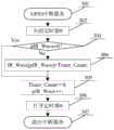
step 301: the GPIO level changes, triggers the microprocessor to enter the interrupt service, and then executes step 302;
step 302: close timer 0 and then go to step 303;
step 303: judging whether the pIR _ Wave is 0 or not, if not, indicating that the infrared waveform acquisition is in progress, executing a step 304, otherwise, indicating that a new round of infrared waveform data acquisition is to be started, executing a step 305;
step 304: saving the data of the Timer _ Count to a position specified by pIR _ Wave in an infrared signal waveform duration buffer IR _ Wave, and then executing step 305;
step 305: resetting the Timer _ Count, moving the pIR _ Wave plus a position backward for storing next data, and then executing step 306;
step 306: turn on timer 0 and then go to step 307;
step 307: and exiting the interrupt service.
Step 401: timer 0 counts to trigger the microprocessor to interrupt into service, and then step 402 is executed;
step 402: adding one to the Timer _ Count to indicate that the interruption time of the Timer 0 is increased once, and then executing step 403;
step 403: judging whether the Timer _ Count is greater than T or notIRIf yes, it indicates that there is no GPIO interruption for a long time, then step 404 is executed, otherwise, it indicates that T is less than TIRThen go to step 405;
step 404: closing the timer 0, setting IsIR _ Wave to be one, applying for subsequent application service processing, and then executing the step 405;
step 405: and exiting the interrupt service.
Step 501: if the precondition for calling the application service is that IsIR _ Wave is equal to 1, starting the subsequent processing and executing step 502;
step 502: searching for low-level data of a synchronous head from a first address (subscript is 0) of an infrared signal waveform duration buffer IR _ Wave, namely searching for a subscript [ x-2] meeting an interval of [ (4500/T0-1), (4500/T0+1) ] in the buffer IR _ Wave data, if the subscript is found, executing a step 503, otherwise, executing a step 507;
step 503: subsequently, checking whether the data of the index [ x-1] in the buffer IR _ Wave satisfies the high level data of the sync head, i.e. whether the data is in the interval of [ (9000/T0-1), (9000/T0+1) ], if so, executing the step 504, otherwise, executing the step 507 if not found;
step 504: after step 501 and 504, the waveform time data of the infrared data is saved after the xth byte (including) in the buffer IR _ Wave, and the splicing four-byte module is called, so that step 505 is executed;
step 505: checking whether the assembled four bytes (system code, user code, data code and data code complement) are correct or not, if so, executing step 506, otherwise, executing step 507;
step 506: executing the task appointed by the infrared data according to the protocol, and then executing step 507;
step 507: setting the pIR-Wave to zero to prepare new infrared waveform data acquisition; setting IsIR _ Wave to zero to indicate that the application service application is processed, and then executing step 508;
step 508: and exiting the service.
Step 601: starting to repeatedly and circularly assemble 4 bytes from the xth byte in the buffer IR _ Wave, wherein the first repeated cycle is 8 times, the circular control variable I is assembled into 1 byte, the second repeated cycle is 4 times, the circular control variable J is used for conveniently expressing, a pointer P is used for assigning an initial value equal to the xth byte address in the buffer IR _ Wave, and then the step 602 is executed;
step 602: the first recirculation control variable I is set to zero, and then step 603 is performed;
step 603: reading the data of the address pointed by the pointer P, judging whether the interval of [560/T0-1,560/T0+1] is satisfied, if so, executing the step 604, otherwise, executing the step 612;
step 604: reading the data of the address pointed by the pointer (P +1), judging whether the interval of [560/T0-1,560/T0+1] is satisfied, if so, executing the step 605, otherwise, executing the step 606;
step 605: obtain the current bit data as logic 0, go to step 608;
step 606: reading the data of the address pointed by the pointer (P +1), judging whether the interval of [1680/T0-1,1680/T0+1] is satisfied, if so, executing the step 607, otherwise, executing the step 612;
step 607: obtain the current bit data as logic 1, go to step 608;
step 608: the pointer P is shifted backward by two bytes, the first recirculation control variable I is incremented by one, and then step 609 is executed;
step 609: checking and judging whether the first recirculation control variable I is smaller than 8, if so, executing step 602, otherwise, executing step 610;
step 610: the second recirculation control variable J is incremented by one, and then step 611 is performed;
step 611: checking and judging whether the second recirculation control variable J is smaller than 4, if so, executing step 602, otherwise, executing step 612;
step 612: and exiting the module service.
Although specific embodiments of the invention have been described above, it will be understood by those skilled in the art that the specific embodiments described are illustrative only and are not limiting to the scope of the invention, and that any equivalent modifications and variations that are obvious from the technical teaching of the present invention are intended to be included within the scope of the appended claims.