CN109155662B - Informing a base station about reception of a beam change instruction by a user equipment - Google Patents
Informing a base station about reception of a beam change instruction by a user equipment Download PDFInfo
- Publication number
- CN109155662B CN109155662B CN201780030805.2A CN201780030805A CN109155662B CN 109155662 B CN109155662 B CN 109155662B CN 201780030805 A CN201780030805 A CN 201780030805A CN 109155662 B CN109155662 B CN 109155662B
- Authority
- CN
- China
- Prior art keywords
- dci
- beam change
- change instruction
- detected
- base station
- Prior art date
- Legal status (The legal status is an assumption and is not a legal conclusion. Google has not performed a legal analysis and makes no representation as to the accuracy of the status listed.)
- Active
Links
Images


Classifications
-
- H—ELECTRICITY
- H04—ELECTRIC COMMUNICATION TECHNIQUE
- H04W—WIRELESS COMMUNICATION NETWORKS
- H04W72/00—Local resource management
- H04W72/04—Wireless resource allocation
- H04W72/044—Wireless resource allocation based on the type of the allocated resource
- H04W72/0466—Wireless resource allocation based on the type of the allocated resource the resource being a scrambling code
-
- H—ELECTRICITY
- H04—ELECTRIC COMMUNICATION TECHNIQUE
- H04B—TRANSMISSION
- H04B7/00—Radio transmission systems, i.e. using radiation field
- H04B7/02—Diversity systems; Multi-antenna system, i.e. transmission or reception using multiple antennas
- H04B7/04—Diversity systems; Multi-antenna system, i.e. transmission or reception using multiple antennas using two or more spaced independent antennas
- H04B7/06—Diversity systems; Multi-antenna system, i.e. transmission or reception using multiple antennas using two or more spaced independent antennas at the transmitting station
- H04B7/0613—Diversity systems; Multi-antenna system, i.e. transmission or reception using multiple antennas using two or more spaced independent antennas at the transmitting station using simultaneous transmission
- H04B7/0615—Diversity systems; Multi-antenna system, i.e. transmission or reception using multiple antennas using two or more spaced independent antennas at the transmitting station using simultaneous transmission of weighted versions of same signal
- H04B7/0617—Diversity systems; Multi-antenna system, i.e. transmission or reception using multiple antennas using two or more spaced independent antennas at the transmitting station using simultaneous transmission of weighted versions of same signal for beam forming
-
- H—ELECTRICITY
- H04—ELECTRIC COMMUNICATION TECHNIQUE
- H04L—TRANSMISSION OF DIGITAL INFORMATION, e.g. TELEGRAPHIC COMMUNICATION
- H04L5/00—Arrangements affording multiple use of the transmission path
- H04L5/003—Arrangements for allocating sub-channels of the transmission path
- H04L5/0048—Allocation of pilot signals, i.e. of signals known to the receiver
-
- H—ELECTRICITY
- H04—ELECTRIC COMMUNICATION TECHNIQUE
- H04W—WIRELESS COMMUNICATION NETWORKS
- H04W72/00—Local resource management
- H04W72/04—Wireless resource allocation
- H04W72/044—Wireless resource allocation based on the type of the allocated resource
- H04W72/046—Wireless resource allocation based on the type of the allocated resource the resource being in the space domain, e.g. beams
-
- H—ELECTRICITY
- H04—ELECTRIC COMMUNICATION TECHNIQUE
- H04W—WIRELESS COMMUNICATION NETWORKS
- H04W72/00—Local resource management
- H04W72/20—Control channels or signalling for resource management
- H04W72/23—Control channels or signalling for resource management in the downlink direction of a wireless link, i.e. towards a terminal
-
- H—ELECTRICITY
- H04—ELECTRIC COMMUNICATION TECHNIQUE
- H04W—WIRELESS COMMUNICATION NETWORKS
- H04W72/00—Local resource management
- H04W72/50—Allocation or scheduling criteria for wireless resources
- H04W72/54—Allocation or scheduling criteria for wireless resources based on quality criteria
- H04W72/542—Allocation or scheduling criteria for wireless resources based on quality criteria using measured or perceived quality
-
- H—ELECTRICITY
- H04—ELECTRIC COMMUNICATION TECHNIQUE
- H04B—TRANSMISSION
- H04B7/00—Radio transmission systems, i.e. using radiation field
- H04B7/02—Diversity systems; Multi-antenna system, i.e. transmission or reception using multiple antennas
- H04B7/04—Diversity systems; Multi-antenna system, i.e. transmission or reception using multiple antennas using two or more spaced independent antennas
- H04B7/06—Diversity systems; Multi-antenna system, i.e. transmission or reception using multiple antennas using two or more spaced independent antennas at the transmitting station
- H04B7/0686—Hybrid systems, i.e. switching and simultaneous transmission
- H04B7/0695—Hybrid systems, i.e. switching and simultaneous transmission using beam selection
-
- H—ELECTRICITY
- H04—ELECTRIC COMMUNICATION TECHNIQUE
- H04W—WIRELESS COMMUNICATION NETWORKS
- H04W88/00—Devices specially adapted for wireless communication networks, e.g. terminals, base stations or access point devices
- H04W88/02—Terminal devices
-
- H—ELECTRICITY
- H04—ELECTRIC COMMUNICATION TECHNIQUE
- H04W—WIRELESS COMMUNICATION NETWORKS
- H04W88/00—Devices specially adapted for wireless communication networks, e.g. terminals, base stations or access point devices
- H04W88/08—Access point devices
Abstract
In the course of the beam change, the base station transmits a beam change instruction to the user equipment to confirm the change from the current beam to another beam. The base station determines to change from the first beam to the second beam. The base station generates a beam change instruction indicating a determination to change from the first beam to the second beam. The base station transmits a beam change instruction to the UE in Downlink Control Information (DCI). The base station determines whether a beam change instruction is detected by the UE.
Description
Cross Reference to Related Applications
The present application claims the benefit of the following applications: U.S. provisional application No.62/348,829, filed on 10.6.2016 and entitled "information BASE STATION differentiation OF USER equilibrium and" information BASE interaction OF BEAM CHANGE interaction ", and U.S. patent application No.15/400,446, filed on 6.1.2017 and entitled" information BASE STATION differentiation OF USER equilibrium and BEAM CHANGE interaction ", both OF which are expressly incorporated herein by reference in their entirety.
Technical Field
The present disclosure relates generally to communication systems, and more particularly to beam change in wireless communications between user equipment and base stations.
Background
Wireless communication systems are widely deployed to provide various telecommunication services such as voice, video, data, messaging, and broadcast. Typical wireless communication systems may utilize multiple-access techniques capable of supporting communication with multiple users by sharing the available system resources. Examples of such multiple-access techniques include Code Division Multiple Access (CDMA) systems, Time Division Multiple Access (TDMA) systems, Frequency Division Multiple Access (FDMA) systems, Orthogonal Frequency Division Multiple Access (OFDMA) systems, single carrier frequency division multiple access (SC-FDMA) systems, and time division synchronous code division multiple access (TD-SCDMA) systems.
These multiple access techniques have been employed in various telecommunications standards to provide a common protocol that enables different wireless devices to communicate on a city, country, region, and even global level. An example telecommunication standard is Long Term Evolution (LTE). LTE is an enhanced set of Universal Mobile Telecommunications System (UMTS) mobile standards promulgated by the third generation partnership project (3 GPP). LTE is designed to: mobile broadband access is supported through improved spectral efficiency, reduced cost, and improved service using OFDMA on the downlink, SC-FDMA on the uplink, and multiple-input multiple-output (MIMO) antenna technology. However, as the demand for mobile broadband access continues to grow, there is a need for further improvements in LTE technology. These improvements may also be applicable to other multiple access techniques and telecommunications standards using these techniques.
Disclosure of Invention
The following presents a simplified summary of one or more aspects in order to provide a basic understanding of such aspects. This summary is not an extensive overview of all contemplated aspects, and is intended to neither identify key or critical elements of all aspects nor delineate the scope of any or all aspects. Its sole purpose is to present some concepts of one or more aspects in a simplified form as a prelude to the more detailed description that is presented later.
With beamforming techniques, the base station may select one of the beams pointing in different directions to transmit the selected beam. After the selection of the beam, the best beam may change, and thus, the base station may determine to change from the current beam to another beam. In the course of the beam change, the base station transmits a beam change instruction to the user equipment to confirm the change from the current beam to another beam. However, the indication that the User Equipment (UE) successfully detected the beam change instruction may be interfered with by a process involving CRC.
In an aspect of the disclosure, a method, a computer-readable medium, and an apparatus are provided. The apparatus may be a base station. The base station determines to change from a first beam to a second beam. The base station generates a beam change instruction indicating a determination to change from the first beam to the second beam. The base station transmits the beam change instruction to the UE in Downlink Control Information (DCI). The base station determines whether the beam change instruction is detected by the UE.
In an aspect, the apparatus may be a base station. The base station includes means for determining to change from a first beam to a second beam. The base station includes means for generating a beam change instruction indicating a determination to change from the first beam to the second beam. The base station includes means for transmitting the beam change instruction to a UE in DCI. The base station includes means for determining whether the beam change instruction is detected by the UE.
In an aspect, the apparatus may be a base station that includes a memory and at least one processor coupled to the memory. The at least one processor is configured to: the method includes determining to change from a first beam to a second beam, generating a beam change instruction indicating the determination to change from the first beam to the second beam, transmitting the beam change instruction in DCI to a UE, and determining whether the beam change instruction is detected by the UE.
In an aspect, a computer-readable medium storing computer executable code for a base station comprises code for: the method includes determining to change from a first beam to a second beam, generating a beam change instruction indicating the determination to change from the first beam to the second beam, transmitting the beam change instruction in DCI to a UE, and determining whether the beam change instruction is detected by the UE.
In another aspect of the disclosure, a method, a computer-readable medium, and an apparatus are provided. The apparatus may be a base station. The base station transmits a beam change instruction in the DCI using the first beam. The base station receives a first sampled signal using the first beam. The base station receives a second sampled signal using a second beam indicated by the beam change instruction. The base station selects one of the first beam and the second beam based on the first sampled signal and the second sampled signal.
In an aspect, the apparatus may be a base station. The base station includes means for transmitting a beam change instruction in DCI using a first beam. The base station includes means for receiving a first sampled signal using the first beam. The base station includes means for receiving a second sampled signal using a second beam indicated by the beam change instruction. The base station includes means for selecting one of the first beam and the second beam based on the first sampled signal and the second sampled signal.
In an aspect, the apparatus may be a base station that includes a memory and at least one processor coupled to the memory. The at least one processor is configured to: transmitting a beam change instruction in the DCI using the first beam; receiving a first sampled signal using the first beam; receiving a second sampled signal using a second beam indicated by the beam change instruction; and selecting one of the first beam and the second beam based on the first sampled signal and the second sampled signal.
In an aspect, a computer-readable medium storing computer executable code for a base station comprises code for: transmitting a beam change instruction in the DCI using the first beam; receiving a first sampled signal using the first beam; receiving a second sampled signal using a second beam indicated by the beam change instruction; and selecting one of the first beam and the second beam based on the first sampled signal and the second sampled signal.
In another aspect of the disclosure, a method, a computer-readable medium, and an apparatus are provided. The apparatus may be a UE. The UE receives DCI from a base station. The UE determines whether a beam change instruction is detected in the DCI. The UE indicates whether the beam change instruction is detected via an uplink transmission associated with the DCI, the uplink transmission comprising at least one of a Physical Uplink Control Channel (PUCCH) or a Physical Uplink Shared Channel (PUSCH). The UE sends the uplink transmission to the base station.
In an aspect, the apparatus may be a UE. The UE includes means for receiving DCI from a base station. The UE includes means for determining whether a beam change instruction is detected in the DCI. The UE includes means for indicating whether the beam change instruction was detected via an uplink transmission associated with the DCI, the uplink transmission including at least one of a PUCCH or a PUSCH. The UE includes means for transmitting the uplink transmission to the base station.
In an aspect, the apparatus may be a UE including a memory and at least one processor coupled to the memory. The at least one processor is configured to: receiving DCI from a base station; determining whether a beam change instruction is detected in the DCI; indicating whether the beam change instruction is detected via an uplink transmission associated with the DCI, the uplink transmission comprising at least one of a PUCCH or PUSCH; and transmitting the uplink transmission to the base station.
In an aspect, a computer-readable medium storing computer executable code for a UE comprises code for: receiving DCI from a base station; determining whether a beam change instruction is detected in the DCI; indicating whether the beam change instruction is detected via an uplink transmission associated with the DCI, the uplink transmission comprising at least one of a PUCCH or PUSCH; and transmitting the uplink transmission to the base station.
To the accomplishment of the foregoing and related ends, the one or more aspects comprise the features hereinafter fully described and particularly pointed out in the claims. The following description and the annexed drawings set forth in detail certain illustrative features of the one or more aspects. These features are indicative, however, of but a few of the various ways in which the principles of various aspects may be employed and the description is intended to include all such aspects and their equivalents.
Drawings
Fig. 1 is a diagram showing an example of a wireless communication system and an access network.
Fig. 2A, 2B, 2C, and 2D are diagrams illustrating LTE examples of a DL frame structure, a DL channel within the DL frame structure, an UL frame structure, and an UL channel within the UL frame structure, respectively.
Fig. 3 is a diagram illustrating an example of an evolved node b (enb) and User Equipment (UE) in an access network.
Fig. 4A and 4B are diagrams illustrating an example of transmission of a beamformed signal between a base station and a UE.
Fig. 5A to 5D show diagrams of a wireless communication system.
Fig. 6A and 6B are exemplary diagrams illustrating communication for beam change between a user equipment and a base station.
Fig. 7A-7D are exemplary diagrams illustrating first, second, third, and fourth aspects of the present disclosure.
Fig. 8A-8C are example diagrams illustrating fifth, sixth, and seventh aspects of the present disclosure.
Fig. 9 is a flow chart of a method of wireless communication in accordance with an aspect of the disclosure.
Fig. 10 is a flow chart of a method of wireless communication in accordance with an aspect of the disclosure.
Fig. 11 is a conceptual data flow diagram illustrating the data flow between different units/components in an exemplary apparatus.
Fig. 12 is a diagram illustrating an example of a hardware implementation of an apparatus using a processing system.
Fig. 13 is a flow chart of a method of wireless communication in accordance with an aspect of the present disclosure.
Fig. 14 is a conceptual data flow diagram illustrating the data flow between different units/components in an exemplary apparatus.
Fig. 15 is a diagram illustrating an example of a hardware implementation of an apparatus using a processing system.
Detailed Description
The detailed description set forth below in connection with the appended drawings is intended as a description of various configurations and is not intended to represent the only configurations in which the concepts described herein may be practiced. The detailed description includes specific details for the purpose of providing a thorough understanding of the various concepts. It will be apparent, however, to one skilled in the art that these concepts may be practiced without these specific details. In some instances, well-known structures and components are shown in block diagram form in order to avoid obscuring such concepts.
Several aspects of a telecommunications system will now be presented with reference to various apparatus and methods. These apparatus and methods are described in the following detailed description and are illustrated in the accompanying drawings by various blocks, components, circuits, processes, algorithms, etc. (collectively referred to as "elements"). These elements may be implemented using electronic hardware, computer software, or any combination thereof. Whether such elements are implemented as hardware or software depends upon the particular application and design constraints imposed on the overall system.
For example, an element, or any portion of an element, or any combination of elements, may be implemented as a "processing system," which includes one or more processors. Examples of processors include: microprocessors, microcontrollers, Graphics Processing Units (GPUs), Central Processing Units (CPUs), application processors, Digital Signal Processors (DSPs), Reduced Instruction Set Computing (RISC) processors, systems-on-chip (SoC), baseband processors, Field Programmable Gate Arrays (FPGAs), Programmable Logic Devices (PLDs), state machines, gated logic, discrete hardware circuits, and other suitable hardware configured to perform the various functions described throughout this disclosure. One or more processors in the processing system may execute software. Software shall be construed broadly to mean instructions, instruction sets, code segments, program code, programs, subprograms, software components, applications, software packages, routines, subroutines, objects, executables, threads of execution, procedures, functions, etc., whether referred to as software, firmware, middleware, microcode, hardware description language, or by other names.
Accordingly, in one or more example embodiments, the functions described may be implemented in hardware, software, or any combination thereof. If implemented in software, the functions may be stored on or encoded as one or more instructions or code on a computer-readable medium. Computer readable media includes computer storage media. A storage media may be any available media that can be accessed by a computer. By way of example, and not limitation, such computer-readable media can comprise Random Access Memory (RAM), Read Only Memory (ROM), Electrically Erasable Programmable ROM (EEPROM), optical disk storage, magnetic disk storage, other magnetic storage devices, combinations of the above types of computer-readable media, or any other medium that can be used to store computer-executable code in the form of instructions or data structures and that can be accessed by a computer.
Fig. 1 is a diagram illustrating an example of a wireless communication system and an access network 100. A wireless communication system, also referred to as a Wireless Wide Area Network (WWAN), includes a base station 102, a UE 104, and an Evolved Packet Core (EPC) 160. Base station 102 may include a macro cell (high power cellular base station) and/or a small cell (low power cellular base station). The macro cell includes an eNB. Small cells include femtocells, picocells and microcells.
The base stations 102 (collectively referred to as evolved Universal Mobile Telecommunications System (UMTS), terrestrial radio access network (E-UTRAN)) interface with the EPC160 through backhaul links 132 (e.g., S1 interface). Base station 102 may perform one or more of the following functions, among others: transmission of user data, radio channel encryption and decryption, integrity protection, header compression, mobility control functions (e.g., handover, dual connectivity), inter-cell interference coordination, connection establishment and release, load balancing, distribution of non-access stratum (NAS) messages, NAS node selection, synchronization, Radio Access Network (RAN) sharing, Multimedia Broadcast Multicast Service (MBMS), user and device tracking, RAN Information Management (RIM), paging, positioning, and delivery of warning messages. The base stations 102 may communicate with each other directly or indirectly (e.g., through the EPC 160) over a backhaul link 134 (e.g., the X2 interface). The backhaul link 134 may be wired or wireless.
The base station 102 may communicate wirelessly with the UE 104. Each of the base stations 102 may provide communication coverage for a respective geographic coverage area 110. There may be overlapping geographic coverage areas 110. For example, the small cell 102 'may have a coverage area 110' that overlaps with the coverage areas 110 of one or more macro base stations 102. A network that includes both small cells and macro cells may be referred to as a heterogeneous network. The heterogeneous network may also include a home evolved node b (enb) (henb), which may provide services to a restricted group referred to as a Closed Subscriber Group (CSG). The communication link 120 between the base station 102 and the UE 104 may include: uplink (UL) (also referred to as reverse link) transmissions from the UE 104 to the base station 102 and/or Downlink (DL) (also referred to as forward link) transmissions from the base station 102 to the UE 104. The communication link 120 may use MIMO antenna techniques including spatial multiplexing, beamforming, and/or transmit diversity. The communication link may be through one or more carriers. The base station 102/UE 104 may use a spectrum of up to Y MHz (e.g., 5, 10, 15, 20MHz) of bandwidth per carrier allocated in carrier aggregation of up to a total of yxmhz (x component carriers) for transmission in each direction. The carriers may or may not be adjacent to each other. With respect to DL and UL, the allocation of carriers may be asymmetric (e.g., more or fewer carriers may be allocated for DL than UL). The component carriers may include a primary component carrier and one or more secondary component carriers. The primary component carrier may be referred to as a primary cell (PCell), and the secondary component carrier may be referred to as a secondary cell (SCell).
The wireless communication system may also include a Wi-Fi Access Point (AP)150 that communicates with a Wi-Fi Station (STA)152 via a communication link 154 in the 5GHz unlicensed spectrum. When communicating in the unlicensed spectrum, the STA 152/AP 150 may perform a Clear Channel Assessment (CCA) prior to communicating to determine whether a channel is available.
The small cell 102' may operate in licensed and/or unlicensed spectrum. When operating in unlicensed spectrum, the small cell 102' may utilize LTE and may use the same 5GHz unlicensed spectrum as used by the Wi-Fi AP 150. Small cells 102' utilizing LTE in unlicensed spectrum may improve coverage and/or increase capacity of an access network. LTE in unlicensed spectrum may be referred to as unlicensed LTE (LTE-U), Licensed Assisted Access (LAA), or MuLTEfire.
Millimeter-wave (MMW) base station 180 may operate in MMW frequencies and/or near MMW frequencies to communicate with UE 182. Extremely High Frequencies (EHF) are part of the RF in the electromagnetic spectrum. The EHF has a range of 30GHz to 300GHz, and a wavelength between 1 millimeter to 10 millimeters. Radio waves in the frequency band may be referred to as millimeter waves. Near mmW may extend down to a frequency of 3GHz with a wavelength of 100 mm. The ultra high frequency (SHF) band extends between 3GHz and 30GHz, also known as centimeter waves. Communications using the mmW/near mmW radio frequency band have extremely high path loss and short range. The mmW base station 180 may use beamforming 184 with the UE 182 to compensate for extremely high path loss and short range.
The EPC160 may include: a Mobility Management Entity (MME)162, other MMEs 164, a serving gateway 166, a Multimedia Broadcast Multicast Service (MBMS) gateway 168, a broadcast multicast service center (BM-SC)170, and a Packet Data Network (PDN) gateway 172. MME 162 may communicate with Home Subscriber Server (HSS) 174. MME 162 is a control node that handles signaling between UE 104 and EPC 160. Generally, the MME 162 provides bearer and connection management. The serving gateway 116 itself connects to the PDN gateway 172 by transmitting all user Internet Protocol (IP) packets through the serving gateway 166. The PDN gateway 172 provides UE IP address allocation as well as other functions. The PDN gateway 172 and BM-SC 170 are connected to an IP service 176. IP services 176 may include the internet, intranets, IP Multimedia Subsystem (IMS), PS streaming services (PSs), and/or other IP services. The BM-SC 170 may provide functionality for MBMS user service provisioning and delivery. The BM-SC 170 may serve as an entry point for content provider MBMS transmissions, may be used to admit and initiate MBMS bearer services in a Public Land Mobile Network (PLMN), and may be used to schedule MBMS transmissions. The MBMS gateway 168 may be used to distribute MBMS traffic to base stations 102 belonging to a Multicast Broadcast Single Frequency Network (MBSFN) area broadcasting a particular service, and may be responsible for session management (start/end) and for collecting eMBMS-related charging information.
A base station may also be referred to as a node B, evolved node B (enb), access point, base transceiver station, radio base station, radio transceiver, transceiver function, Basic Service Set (BSS), Extended Service Set (ESS), or some other suitable terminology. Base station 102 provides an access point for UE 104 to EPC 160. Examples of UEs 104 include cellular phones, smart phones, Session Initiation Protocol (SIP) phones, laptops, Personal Digital Assistants (PDAs), satellite radios, global positioning systems, multimedia devices, video devices, digital audio players (e.g., MP3 players), cameras, game consoles, tablets, smart devices, wearable devices, or any other similarly functioning device. The UE 104 may also be referred to as a station, mobile station, subscriber station, mobile unit, subscriber unit, wireless unit, remote unit, mobile device, wireless communication device, remote device, mobile subscriber station, access terminal, mobile terminal, wireless terminal, remote terminal, handheld device, user agent, mobile client, or some other suitable terminology.
Referring again to fig. 1, in certain aspects, the UE 104/eNB 102 may be configured to: enabling the eNB 102 to more reliably determine whether the UE 104 has detected a beam change instruction from the eNB 102 (198).
Fig. 2A is a diagram 200 showing an example of a DL frame structure in LTE. Fig. 2B is a diagram 230 showing an example of channels within a DL frame structure in LTE. Fig. 2C is a diagram 250 illustrating an example of the UL frame structure in LTE. Fig. 2D is a diagram 280 illustrating an example of channels within the UL frame structure in LTE. Other wireless communication technologies may have different frame structures and/or different channels. In LTE, one frame (10ms) may be divided into 10 equally sized subframes. Each subframe may include two consecutive slots. A resource grid may be used to represent two slots, each slot including one or more time-concurrent Resource Blocks (RBs) (also referred to as physical RBs (prbs)). The resource grid is divided into a plurality of Resource Elements (REs). In LTE, for a normal cyclic prefix, an RB contains 12 consecutive subcarriers in the frequency domain and contains 7 consecutive symbols in the time domain (OFDM symbols for DL; SC-FDMA symbols for UL), for a total of 84 REs. For an extended cyclic prefix, an RB contains 12 consecutive subcarriers in the frequency domain and 6 consecutive symbols in the time domain, for a total of 72 REs. The number of bits carried by each RE depends on the modulation scheme.
As shown in fig. 2A, some of the REs carry DL reference (pilot) signals (DL-RS) used for channel estimation at the UE. The DL-RS may include: cell-specific reference signals (CRS) (also sometimes referred to as common RS), UE-specific reference signals (UE-RS), and channel state information reference signals (CSI-RS). Fig. 2A shows a diagram for antenna ports 0, 1, 2 and 3 (indicated as R, respectively)0、R1、R2And R3) CRS of, UE-RS for antenna port 5 (indicated as R)5) And CSI-RS (indicated as R) for antenna port 15. Fig. 2B shows an example of various channels within the DL subframe of a frame. The Physical Control Format Indicator Channel (PCFICH) is within symbol 0 of slot 0 and carries a Control Format Indicator (CFI) indicating whether the Physical Downlink Control Channel (PDCCH) occupies 1, 2 or 3 symbols (fig. 2B shows the PDCCH occupying 3 symbols). The PDCCH carries Downlink Control Information (DCI) in one or more Control Channel Elements (CCEs), each CCE including nine RE groups (REGs), each REG including four consecutive REs in an OFDM symbol. The UE may be configured to also carry DUE-specific enhanced pdcch (epdcch) of CI. The ePDCCH may have 2, 4, or 8 RB pairs (fig. 2B shows two RB pairs, each subset including one RB pair). A physical hybrid automatic repeat request (ARQ) (HARQ) indicator channel (PHICH) is also within symbol 0 of slot 0 and carries HARQ Indicators (HI) indicating HARQ Acknowledgement (ACK)/negative ACK (nack) feedback based on a Physical Uplink Shared Channel (PUSCH). The Primary Synchronization Channel (PSCH) is within symbol 6 of slot 0 in subframes 0 and 5 of the frame and carries the Primary Synchronization Signal (PSS) and the physical layer identity used by the UE to determine subframe timing. The Secondary Synchronization Channel (SSCH) is within symbol 5 of slot 0 in subframes 0 and 5 of the frame and carries a Secondary Synchronization Signal (SSS) used by the UE to determine the physical layer cell identification group number. Based on the physical layer identity and the physical layer cell identity group number, the UE may determine a Physical Cell Identifier (PCI). Based on the PCI, the UE may determine the location of the aforementioned DL-RS. The Physical Broadcast Channel (PBCH) is within symbols 0, 1, 2, 3 in slot 1 of subframe 0 of the frame and carries a Master Information Block (MIB). The MIB provides the number of RBs in the DL system bandwidth, PHICH configuration, and System Frame Number (SFN). The Physical Downlink Shared Channel (PDSCH) carries user data, broadcast system information such as System Information Blocks (SIBs) that are not transmitted through the PBCH, and a paging message.
As shown in fig. 2C, some of the REs carry demodulation reference signals (DM-RS) for channel estimation at the eNB. The UE may additionally transmit a Sounding Reference Signal (SRS) in the last symbol of the subframe. The SRS may have a comb structure, and the UE may transmit the SRS on one of the combs. SRS may be used by the eNB for channel quality estimation to enable frequency-dependent scheduling on the UL. Fig. 2D shows an example of various channels within the UL subframe of a frame. Based on a Physical Random Access Channel (PRACH) configuration, the PRACH may be within one or more subframes in a frame. The PRACH may include six consecutive RB pairs within a subframe. The PRACH allows the UE to perform initial system access and achieve UL synchronization. The Physical Uplink Control Channel (PUCCH) may be located on the edge of the UL system bandwidth. The PUCCH carries Uplink Control Information (UCI), e.g., scheduling request, Channel Quality Indicator (CQI), Precoding Matrix Indicator (PMI), Rank Indicator (RI), and HARQ ACK/NACK feedback. The PUSCH carries data and may additionally be used to carry Buffer Status Reports (BSRs), Power Headroom Reports (PHR), and/or UCI.
Fig. 3 is a block diagram of an eNB 310 in communication with a UE 350 in an access network. In the DL, IP packets from EPC160 may be provided to controller/processor 375. Controller/processor 375 implements layer 3 and layer 2 functions. Layer 3 includes a Radio Resource Control (RRC) layer, and layer 2 includes a Packet Data Convergence Protocol (PDCP) layer, a Radio Link Control (RLC) layer, and a Medium Access Control (MAC) layer. The controller/processor 375 provides: RRC layer functions associated with: broadcast of system information (e.g., MIB, SIB), RRC connection control (e.g., RRC connection paging, RRC connection establishment, RRC connection modification, and RRC connection release), inter-Radio Access Technology (RAT) mobility, and measurement configuration for UE measurement reports; PDCP layer functions associated with: header compression/decompression, security (encryption, decryption, integrity protection, integrity verification) and handover support functions; RLC layer functions associated with: transmission of upper layer Packet Data Units (PDUs), error correction by ARQ, concatenation, segmentation and reassembly of RLC Service Data Units (SDUs), re-segmentation of RLC data PDUs, and re-ordering of RLC data PDUs; and MAC layer functions associated with: mapping between logical channels and transport channels, multiplexing of MAC SDUs onto Transport Blocks (TBs), demultiplexing of MAC SDUs from TBs, scheduling information reporting, error correction by HARQ, priority handling, and logical channel prioritization.
The Transmit (TX) processor 316 and the Receive (RX) processor 370 perform layer 1 functions associated with various signal processing functions. Layer 1 (which includes the Physical (PHY) layer) may include: error detection on the transport channel, Forward Error Correction (FEC) encoding/decoding of the transport channel, interleaving, rate matching, mapping onto the physical channel, modulation/demodulation of the physical channel, and MIMO antenna processing. The TX processor 316 processes the mapping to the signal constellation based on various modulation schemes (e.g., Binary Phase Shift Keying (BPSK), Quadrature Phase Shift Keying (QPSK), M-phase shift keying (M-PSK), M-quadrature amplitude modulation (M-QAM)). The coded and modulated symbols may then be split into parallel streams. Each stream may then be mapped to an OFDM subcarrier, multiplexed with a reference signal (e.g., pilot) in the time and/or frequency domain, and then combined together using an Inverse Fast Fourier Transform (IFFT) to produce a physical channel carrying a time-domain OFDM symbol stream. The OFDM streams are spatially precoded to produce a plurality of spatial streams. The channel estimates from channel estimator 374 may be used to determine coding and modulation schemes and for spatial processing. The channel estimate may be derived from a reference signal and/or channel condition feedback transmitted by the UE 350. Each spatial stream may then be provided to a different antenna 320 via a respective transmitter 318 TX. Each transmitter 318TX may modulate an RF carrier with a respective spatial stream for transmission.
At the UE 350, each receiver 354RX receives a signal through its respective antenna 352. Each receiver 354RX recovers information modulated onto an RF carrier and provides the information to a Receive (RX) processor 356. The TX processor 368 and the RX processor 356 implement layer 1 functions associated with various signal processing functions. The RX processor 356 may perform spatial processing on the information to recover any spatial streams destined for the UE 350. If multiple spatial streams are destined for the UE 350, the RX processor 356 can combine them into a single OFDM symbol stream. The RX processor 356 then transforms the OFDM symbol stream from the time-domain to the frequency-domain using a Fast Fourier Transform (FFT). The frequency domain signal comprises a separate OFDM symbol stream for each subcarrier of the OFDM signal. The symbols on each subcarrier, as well as the reference signal, are recovered and demodulated by determining the most likely signal constellation points transmitted by the eNB 310. These soft decisions may be based on channel estimates computed by the channel estimator 358. The soft decisions are then decoded and deinterleaved to recover the data and control signals that were originally transmitted by the eNB 310 on the physical channel. The data and control signals are then provided to a controller/processor 359, which controller/processor 359 implements layer 3 and layer 2 functions.
The controller/processor 359 can be associated with memory 360 that stores program codes and data. The memory 360 may be referred to as a computer-readable medium. In the UL, the controller/processor 359 provides demultiplexing between transport and logical channels, packet reassembly, deciphering, header decompression, and control signal processing to recover IP packets from the EPC 160. The controller/processor 359 is also responsible for error detection using ACK and/or NACK protocols to support HARQ operations.
Similar to the functionality described in connection with the DL transmission by the eNB 310, the controller/processor 359 provides: RRC layer functions associated with: system information (e.g., MIB, SIB) acquisition, RRC connection, and measurement reporting; PDCP layer functions associated with: header compression/decompression, and security (encryption, decryption, integrity protection, integrity verification); RLC layer functions associated with: transmission of upper layer PDU, error correction by ARQ, concatenation, segmentation and reassembly of RLC SDUs, re-segmentation of RLC data PDUs, and re-sequencing of RLC data PDUs; and MAC layer functions associated with: mapping between logical channels and transport channels, multiplexing of MAC SDUs onto TBs, demultiplexing of MAC SDUs from TBs, scheduling information reporting, error correction by HARQ, priority handling, and logical channel prioritization.
The TX processor 368 may use channel estimates derived by a channel estimator 358 from reference signals or feedback transmitted by the eNB 310 to select an appropriate coding and modulation scheme and to facilitate spatial processing. The spatial streams generated by TX processor 368 may be provided to different antennas 352 via respective transmitters 354 TX. Each transmitter 354TX may modulate an RF carrier with a respective spatial stream for transmission.
At the eNB 310, the UL transmissions are processed in a similar manner as described in connection with the receiver functionality at the UE 350. Each receiver 318RX receives a signal through its corresponding antenna 320. Each receiver 318RX recovers information modulated onto an RF carrier and provides the information to an RX processor 370.
The controller/processor 375 can be associated with a memory 376 that stores program codes and data. The memory 376 may be referred to as a computer-readable medium. In the UL, the controller/processor 375 provides demultiplexing between transport and logical channels, packet reassembly, deciphering, header decompression, control signal processing to recover IP packets from the UE 350. IP packets from controller/processor 375 may be provided to EPC 160. The controller/processor 375 is also responsible for error detection using ACK and/or NACK protocols to support HARQ operations.
Wireless communication systems utilizing narrow bandwidth and high frequency carriers are being deployed and have been deployed. The mmW system may be used for wireless communication at a high transmission rate. In mmW systems, path loss may be high due to the high carrier frequency (e.g., 28 GHz). For example, the carrier frequency for mmW communication may be 10 times higher than carrier frequencies for other types of wireless communication. As a result, mmW systems may experience approximately 20dB higher path loss compared to other types of wireless communication systems that utilize lower carrier frequencies. To mitigate path loss in mmW systems, a base station may perform transmissions in a directional manner, where transmissions are beamformed to direct transmissions of beams in different directions.
Using a higher carrier frequency for wireless communication results in shorter wavelengths, which may allow a higher number of antennas to be implemented within a given antenna array length (than could be achieved when using a lower carrier frequency). Thus, mmW systems (using high carrier frequencies) may use a higher number of antennas in the base station and/or UE. For example, a BS may have 128 or 256 antennas, while a UE may have 8, 16 or 24 antennas. With a higher number of antennas, beamforming techniques can be used to digitally change the direction of the beam by applying different phases to different antennas. Because beamforming in mmW systems provides narrower beams for increased gain, a base station may transmit narrower beams in multiple directions when transmitting synchronization signals to provide coverage over a wider area using multiple narrower beams.
One challenge when using beamforming for mmW systems is due to the directional nature of the beamformed beam. Due to the directional nature of the beamformed beam, the base station should point the beam directly at the UE so that the direction of the beam is aligned with the location of the UE to provide more antenna reception gain at the UE. If the directions of the beams are not properly aligned, the antenna gain at the UE may be reduced (e.g., resulting in a low SNR, a higher block error rate, etc.). Further, when a UE enters the coverage area of a mmW system and receives data transmitted from a base station on a mmW, the base station should be able to determine the best beam (e.g., the beam with the highest signal strength, the highest SNR, the lowest error rate, etc.) for mmW communication with a particular UE. Accordingly, the base station may transmit Beam Reference Signals (BRSs) in multiple directions (or all directions) so that the UE may identify the best beam of the one or more beams received from the base station based on measurements of the BRSs. In mmW communication, a base station may also transmit a Primary Synchronization Signal (PSS), a Secondary Synchronization Signal (SSS), an Extended Synchronization Signal (ESS), and a PBCH signal for synchronization and for broadcasting system information. In mmW communications, such signals may be directionally transmitted via multiple beams to enable UEs to receive such synchronization and system information at various locations within the coverage area of a base station.
If there are multiple antenna ports (multiple sets of antennas) in the base station, the base station may transmit multiple beams per symbol. For example, the base station may scan in a cell-specific manner in a first symbol of the synchronization subframe using multiple antenna ports in a set of multiple directions. The base station may then scan in another set of multiple directions using multiple antenna ports in a cell-specific manner in another symbol of the synchronization subframe. Each antenna port may include a set of antennas. For example, an antenna port comprising a group of antennas (64 antennas) may transmit one beam, and several antenna ports may each transmit a beam, each beam being in a different direction. Thus, if there are four antenna ports, the four antenna ports may sweep through four directions (e.g., transmit four beams in four different directions).
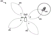
Fig. 4A and 4B are diagrams illustrating an example of transmission of a beamformed signal between a Base Station (BS) and a UE. The BS may be embodied as a BS (mmW BS) in a mmW system. Referring to fig. 4A, a diagram 400 illustrates a BS 404 of a mmW system transmitting beamformed signals 406 (e.g., beam-reference signals) in different transmit directions (e.g., directions A, B, C and D). In one example, the BS 404 can sweep through the transmit directions according to the order A-B-C-D. In another example, the BS 404 may sweep the transmit direction according to the order B-D-A-C. Although four transmission directions and two transmission orders are described with respect to fig. 4A, any number of different transmission directions and transmission orders are contemplated.
After transmitting the signal, the BS 404 may switch to a receive mode. In the receive mode, the BS 404 may sweep through different receive directions in an order or pattern corresponding (mapped) to the order or pattern in which the BS 404 previously transmitted synchronization/discovery signals in different transmit directions. For example, if the BS 404 previously sent synchronization/discovery signals in the transmit direction according to the order a-B-C-D, the BS 404 may sweep the receive direction according to the order a-B-C-D in an attempt to receive an association signal from the UE 402. In another example, if the BS 404 previously transmitted the synchronization/discovery signal in the transmit direction according to the order B-D-a-C, the BS 404 may sweep the receive direction according to the order B-D-a-C in an attempt to receive an association signal from the UE 402.
The propagation delay on each beamformed signal allows the UE 402 to perform a Receive (RX) scan. The UE 402 in receive mode may sweep through different receive directions to attempt to detect synchronization/discovery signals via the beamformed signals 406 (see fig. 4B). One or more of the synchronization/discovery signals 406 may be detected by the UE 402. When a strong synchronization/discovery signal 406 is detected, the UE 402 may determine the best transmit direction of the BS 404 and the best receive direction of the UE 402 corresponding to the strong synchronization/discovery signal. For example, the UE 402 may determine initial antenna weights/directions for the strong synchronization/discovery signals 406 and may also determine the time and/or resources at which the BS 404 is expected to best receive the beamformed signals (e.g., with high signal strength). Thereafter, the UE 402 may attempt to associate with the BS 404 via the beamformed signals.
The BS 404 may sweep through multiple directions in a cell-specific manner using multiple ports in the first symbol of the synchronization subframe. For example, BS 404 may sweep through different transmit directions (e.g., directions A, B, C and D) in a cell-specific manner using four ports in the first symbol of the synchronization subframe. In an aspect, the different transmit directions (e.g., directions A, B, C and D) may be considered "coarse" beam directions. In an aspect, the Beam Reference Signals (BRSs) may be transmitted in different transmit directions (e.g., directions A, B, C and D).
In an aspect, the BS 404 may sweep through different transmit directions (e.g., directions A, B, C and D) in a cell-specific manner using four ports in the second symbol of the synchronization subframe. The synchronization beam may occur in a second symbol of the synchronization subframe.
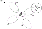
Referring to diagram 420 of fig. 4B, the UE 402 may listen for beamformed discovery signals in different reception directions (e.g., directions E, F, G and H). In one example, the UE 402 may sweep through the receive direction according to the order E-F-G-H. In another example, the UE 402 may sweep the receive direction according to the sequence F-H-E-J. Although four receive directions and two receive orders are described with respect to fig. 4B, any number of different receive directions and receive orders are contemplated.
The UE 402 may attempt association with the BS 404 by transmitting a beamformed signal 426 (e.g., an association signal or another indication of a best "coarse" beam or a best "fine" beam) in different transmit directions (e.g., directions E, F, G and H). In an aspect, the UE 402 may transmit the association signal 426 by transmitting along the best receive direction of the UE 402 at a time/resource at which the BS 404 is expected to best receive the association signal. The BS 404 in receive mode may sweep through different receive directions and detect an association signal 426 from the UE 402 during one or more time slots corresponding to the receive directions. Upon detecting the strong association signal 426, the BS 404 may determine the best transmit direction for the UE 402 and the best receive direction for the BS 404 corresponding to the strong association signal. For example, the BS 404 may determine initial antenna weights/directions for the strongly associated signals 426 and may also determine the time and/or resources at which the UE 402 is expected to optimally receive the beamformed signals. Any of the processes discussed above with respect to fig. 4A and 4B may be refined or repeated over time such that the UE 402 and BS 404 eventually learn the best transmit and receive directions for establishing a link with each other. Such refinement and repetition may be referred to as beam training.
In an aspect, the BS 404 may select an order or pattern for transmitting synchronization/discovery signals according to a number of beamforming directions. The BS 404 may then transmit the signal for an amount of time long enough for the UE 402 to sweep through a certain number of beamforming directions to attempt to detect the synchronization/discovery signal. For example, the BS beamforming direction may be represented by N, where N is an integer from 0 to N, which is the maximum number of transmit directions. Further, the UE beamforming direction may be represented by K, where K is an integer from 0 to K, and K is the maximum number of receive directions. When the UE 402 detects a synchronization/discovery signal from the BS 404, the UE 402 may find that the strongest synchronization/discovery signal is received when the UE 402 beamforming direction is k-2 and the BS 404 beamforming direction is n-3. Thus, the UE 402 may respond (transmit beamformed signals) to the BS 404 in the corresponding response time slot using the same antenna weights/directions. That is, the UE 402 may transmit a signal to the BS 404 using the UE 402 beamforming direction k 2 during a time slot when the BS 404 is expected to perform a receive scan at the BS 404 beamforming direction n 3.
In mmW systems, the path loss may be relatively high. The transmission may be directional to mitigate path loss. The base station may transmit one or more beam reference signals by scanning in multiple directions so that a User Equipment (UE) may identify the best "coarse" beam. Further, the base station may transmit a beam refinement request signal so that the UE may track the "fine" beam. If the "coarse" beam identified by the UE changes, the UE may need to inform the base station so that the base station may perform beam training for one or more new "fine" beams for the UE.
In various aspects, a base station may transmit a Beam Reference Signal (BRS) by scanning in all directions so that a User Equipment (UE) may determine an index or Identifier (ID) of a best "coarse" beam. The base station may also transmit a beam refinement request signal so that the UE may track the "fine" beam. The UE may signal the best "fine" beam to the base station. The base station and the UE may have to continually update and/or recover the beams to maintain the communication link.
In fig. 4A and 4B, the base station 404 and the UE 402 may sweep four directions in a cell-specific manner using four ports in the first symbol of the synchronization subframe. The four directions may be considered "coarse" beam directions. In an aspect, a BRS may be included in the first symbol. In an aspect, the base station 404 and the UE 402 may sweep four different directions in a cell-specific manner using four ports in the second symbol of the synchronization subframe. Note that although the beams are shown as being adjacent, the beams transmitted during the same symbol may not be adjacent.
Fig. 5A to 5G are diagrams illustrating examples of transmission of beamformed signals between a Base Station (BS) and a UE. BS 504 may be a BS in a mmW system (mmW BS). Although some beams are shown adjacent to each other, in different aspects such an arrangement may be different (e.g., beams transmitted in the same symbol may not be adjacent to each other).
In an aspect, a set of beams may contain eight different beams. For example, fig. 5A shows eight beams 521, 522, 523, 524, 525, 526, 527, 528 for eight directions. In aspects, the BS 504 may be configured to beamform at least one of the beams 521, 522, 523, 524, 525, 526, 527, 528 for transmission toward the UE 502.
In an aspect, a BS may transmit a first tracking signal (e.g., BRS) in multiple directions during a synchronization subframe. In an aspect, the transmission may be cell-specific. Referring to fig. 5B, the BS 504 may transmit beams 521, 523, 525, 527 in four directions. In an aspect, the beams 521, 523, 525, 527 transmitted in the four directions may be odd indexed beams 521, 523, 525, 527 for the four directions of the possible eight beams of the set of beams. For example, the BS 504 can transmit beams 521, 523, 525, 527 in directions adjacent to other beams 522, 524, 526, 528 that the BS 504 is configured to transmit. In an aspect, a configuration in which the BS 504 transmits odd-indexed beams 521, 523, 525, 527 for four directions may be considered a "coarse" set of beams.
In fig. 5C, the UE 502 may determine the strongest or preferred beam index. For example, the UE 502 may determine that the beam 525 carrying the BRS is strongest or best (e.g., has the highest signal strength). The UE 502 may send an indication 560 of the beam index of the beam 525 to the BS 504. In an aspect, the indication 560 may include a request to transmit a second tracking signal (e.g., a Beam Refinement Reference Signal (BRRS)). The BRRS may be UE-specific.
In fig. 5D, BS 504 may transmit a second tracking signal (e.g., BRRS) based on the index included in indication 560. For example, the UE 502 may indicate that the first beam 525 is the strongest or best, and in response, the BS 504 may transmit the plurality of beams 524, 525, 526 to the UE 502 based on the indicated beam index. In an aspect, the beams 524, 525, 526 transmitted based on the indicated beam index may be considered a "fine" set of beams. In an aspect, the BRRS may be transmitted in each of the beams 524, 525, 526 in the fine beam set. In an aspect, the beams 524, 525, 526 in the fine beam set may be adjacent.
Based on the one or more BRRS received in the beams 524, 525, 526 of the fine beam set, the UE 502 may send a second indication 565 to the BS 504 to indicate the best "fine" beam (e.g., the beam providing the highest SNR, lowest error rate, etc.). In an aspect, the second indication 565 may use 2 bits to indicate the selected beam. For example, UE 502 may transmit an indication 565 indicating the selected beam 525. The BS 504 may then communicate with the UE 502 using the selected beam 525.
After the selection of the transmission beam to be transmitted from the base station, the optimal transmission beam from the base station to the UE may change over time. The best transmit beam may be the beam that provides the highest signal strength, highest SNR, and/or lowest error rate. The base station may periodically transmit the BRSs in multiple directions (or all directions). Based on the reception of the BRS, if the UE determines that another transmission beam in a certain direction for transmitting the BRS is better than the current transmission beam, the UE may determine to change the transmission beam of the base station from the current beam to another transmission beam. To change to another transmit beam, the UE may utilize a beam selection process, as discussed above, involving beam refinement based on a "coarse" beam set.
When the UE determines to change the beam of the base station from the current beam to the second beam, the UE notifies the base station of the determination to change to the second beam. The current beam and the second beam may be a transmission beam of the base station or a reception beam of the base station. In response, the base station sends a beam change instruction to the UE (e.g., via the PDCCH) to indicate whether the base station changes the current beam to the second beam. In an aspect, when the UE notifies the base station about the change, the base station may determine not to change the current beam to the second beam if the change from the current beam to the second beam is inappropriate (e.g., if the second beam interferes with a neighboring base station). When the base station determines that a change from the current beam to the second beam is appropriate (e.g., does not interfere with neighboring base stations), the base station sends a beam change instruction to the UE (e.g., via the PDCCH) to indicate that the base station is to change beams. In an aspect, a portion (e.g., a certain number of bits) of the DCI included in the PDCCH is used to convey a beam change instruction to indicate whether the base station is to change from the current beam to the second beam. If the UE receives a beam change instruction indicating that the base station is to change from the current beam to the second beam, the UE may change the beam of the UE to a corresponding reception beam corresponding to the second beam.
The base station should confirm that the UE has received the beam change instruction. If the base station cannot determine that the UE has received the beam change instruction, the base station may not change the current beam of the base station. At least one of several methods may be used for the base station to determine whether the UE receives a beam change instruction. For example, the base station may transmit a beam change instruction in DCI for a downlink grant or DCI for an uplink grant, and the UE may respond by transmitting an ACK (for indicating that the UE received the beam change instruction) or a NACK (for indicating that the UE did not receive the beam change instruction). When the base station receives the ACK, the base station may acknowledge that the UE received the beam change instruction. Bits may be reserved in the PDCCH for DCI for a downlink grant and/or DCI for an uplink grant. Downlink transmission and/or uplink transmission may occur at the (n + k) th subframe, and beam change may occur at the (n + k ') th subframe, where k' > k. That is, the UE may receive a beam change instruction included in at least one of DCI for a downlink grant or DCI for an uplink grant at an nth subframe, and then transmit an ACK at an (n + k) th subframe if the UE receives the beam change instruction, so that the base station may change a beam at the (n + k ') th subframe, where k' is greater than k.
The base station may transmit DCI in a PDCCH and may also transmit PDSCH to the UE within one HARQ process. If the base station transmits DCI indicating to the UE that the base station may change the transmission beam of the base station for the UE, the base station should be informed whether the UE has successfully decoded the DCI to detect the beam change instruction regardless of whether the CRC for the corresponding PDSCH passes or fails. In an aspect, if the UE is able to decode DCI from the PDCCH and detects a beam change instruction in the DCI, the UE should indicate to the base station that the beam change instruction was successfully detected. When the base station receives an indication that the beam change instruction is successfully detected at the UE, the base station may change the beam of the base station to another beam. As discussed above, the base station may change the beam at the (n + k ') th subframe, while the DCI is received in the nth subframe and the corresponding PDSCH is received in the (n + k) th subframe, where k' is greater than k.
If the DCI is for an uplink grant, the base station may detect the PUSCH to determine whether the UE has decoded the DCI. The UE does not transmit PUSCH if the UE does not decode DCI for an uplink grant. Thus, if the base station does not detect PUSCH from the UE, the base station may determine that the UE has not decoded DCI for the uplink grant. Bits/parts in the DCI are typically reserved to convey the beam change instruction. Thus, the transmission of PUSCH by the UE indicates that the UE has detected a beam change instruction by successfully decoding DCI. The base station may determine whether the UE has attempted to transmit PUSCH in at least one of several ways. For example, the base station may measure the energy of the DMRS of the PUSCH and/or may attempt to decode the DMRS indicating that the beam change request was successfully detected. For example, if the energy of the DMRS is greater than the energy threshold, the base station may determine that the UE has successfully decoded DCI for the uplink grant and detected the beam change instruction. On the other hand, if the energy of the DMRS is less than or equal to the energy threshold, the base station may determine that the UE has not successfully decoded the DCI. In another example, if the base station is able to decode the DMRS, the base station may determine that the UE has successfully decoded the DCI for the uplink grant and detected the beam change instruction. On the other hand, if the base station is unable to decode the DMRS, the base station may determine that the UE has not successfully decoded the DCI. In another example, the base station may use the energy of the traffic of the PUSCH to determine whether the UE has successfully decoded DCI for the uplink grant with the beam change instruction detected. If the energy of the received samples of uplink traffic (e.g., PUSCH traffic) is greater than the energy threshold, the base station may determine that the UE has successfully decoded DCI for the uplink grant and detect the beam change instruction. On the other hand, if the energy of the received samples of uplink traffic (e.g., PUSCH traffic) is less than or equal to the energy threshold, the base station may determine that the UE has not successfully decoded the DCI.
In case of using DCI for a downlink grant, since the PUCCH may contain an ACK/NACK response for another HARQ process unrelated to the beam change request, the UE may not correctly indicate whether the beam change request is successfully detected when the ACK/NACK response is transmitted in the PUCCH. NACK may be a default response when DCI is not decoded. When the base station transmits DCI for a downlink grant via the PDCCH, the UE attempts to decode the PDCCH to recover the DCI including the beam change instruction. The UE may determine, based on the DCI, that the wave speed change may occur at the (n + k ') th subframe when the UE receives the PDSCH at the (n + k) th subframe, where k' is greater than k. If the UE receives the PDSCH at the (n + k) th subframe but cannot decode the PDSCH, a Cyclic Redundancy Check (CRC) for the PDSCH fails. In such a scenario, the UE sends a NACK to the base station on the PUCCH, since the UE cannot decode the PDSCH. Therefore, even in the case where the UE has successfully decoded the PDCCH, if the UE cannot decode the PDSCH, the UE may still transmit a NACK to the base station on the PUCCH. In such a case, since the UE transmits NACK to the base station, the base station may erroneously determine that the UE has not successfully decoded DCI even when the UE successfully decodes the DCI to obtain the beam change instruction. In another example, the UE may send a combined ACK/NACK response for multiple HARQ processes. The UE may decode the PDCCH conveying the beam change instruction in the DCI and may also successfully decode the PDSCH corresponding to the PDCCH. However, the UE may not successfully decode the PDCCH or PDSCH of another HARQ process. If the UE transmits a combined ACK/NACK response for two different PDSCH transmissions, the UE transmits a NACK to the base station even if the UE successfully decodes the beam change instruction of the PDCCH. Even if the UE successfully decodes the DCI to obtain the beam change instruction, the base station may erroneously determine that the UE has not successfully decoded the DCI. In summary, if the UE decodes DCI to successfully detect a beam change instruction, but the CRC for the PDSCH fails, the UE may transmit a NACK on the PUCCH due to the CRC failure. In this case, the UE is notified that a beam change should occur based on the beam change instruction, but the base station may incorrectly determine that the UE has not detected the beam change instruction from the DCI based on the NACK. Accordingly, a method that addresses the above-identified problems is desired.
Fig. 6A and 6B are exemplary diagrams illustrating communication for beam change between a user equipment and a base station. Fig. 6A is an example diagram 600 illustrating communication for beam change between a UE and a base station when DCI for a downlink grant is used. Example diagram 600 relates to communications between a UE 602 and a base station 604. At 610, the UE 602 indicates to the base station 604 that the UE has determined to change the current beam of the base station 604 to another beam (e.g., when it is determined that there is a better beam that provides a higher SNR than the current beam). At 612, the base station 604 generates a beam change instruction indicating whether the base station 604 is to perform a beam change from the current beam to another beam, and includes the beam change instruction in DCI for a downlink grant. At 614, the base station transmits a PDDCH including the DCI and also transmits a PDSCH. At 622, the UE successfully decodes the DCI and detects the beam change instruction. At 624, the UE performs CRC for the PDSCH. At 630, the UE sends an ACK/NACK response via the PUCCH based on whether the UE detected the beam change instruction based on whether the UE successfully decoded the DCI. Based on the ACK/NACK, the base station 604 determines whether to change the current beam to another beam at 642. As discussed above, in the case where DCI is used for a DL grant, even if the UE 602 successfully decodes the DCI (e.g., at 622) and detects a beam change instruction, if the CRC for the PDSCH fails, the UE 602 may still transmit a NACK via the PUCCH (e.g., at 624).
Fig. 6B is an example diagram 650 illustrating communication for beam change between a UE and a base station when DCI for an uplink grant is used. Example diagram 650 relates to communications between UE 602 and base station 604. At 660, the UE 602 indicates to the base station 604 that the UE has determined to change the current beam of the base station 604 to another beam (e.g., when it is determined that there is a better beam than the current beam). At 662, the base station 604 generates a beam change instruction indicating whether the base station 604 is to perform a beam change from the current beam to another beam, and includes the beam change instruction in the DCI for the uplink grant. At 664, the base station transmits the PDCCH including the DCI. At 672, the UE successfully decodes the DCI and detects the beam change instruction. At 680, if the UE successfully decodes the DCI and detects a beam change instruction, the UE transmits PUSCH. Based on the PUSCH, the base station 604 determines whether to change the current beam to another beam at 642. Example diagram 650 does not exhibit the same problems as example diagram 600, in example diagram 600, even if UE 602 successfully decodes DCI, UE 602 of example diagram 600 may still transmit a NACK as long as the CRC for the PDSCH fails.
According to an aspect of the present disclosure, when the base station generates a beam change instruction for instructing the base station to change from a current beam to another beam, the base station transmits the beam change instruction to the UE in DCI. The beam associated with the beam change instruction may be a transmit beam of the base station or a receive beam of the base station. When the UE receives DCI from a base station, the UE decodes the DCI to attempt to detect a beam change instruction in the DCI. The UE may then indicate to the base station whether the UE has detected a beam change instruction, such that the base station may determine whether the UE has detected a beam change instruction based on the indication. If the base station determines that the beam change instruction is detected by the UE, the base station may change from the current beam to another beam. Several methods may be used to implement features according to this aspect of the disclosure, as discussed below.
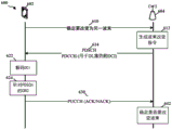
According to a first aspect of the present disclosure, a base station may transmit a beam change instruction using DCI for an uplink grant. Thus, for example, when DCI is used to transmit a beam change instruction to a UE, the base station may utilize DCI for an uplink grant. Fig. 7A is an example diagram 700 illustrating a first aspect of the present disclosure. After the base station 704 determines to change the beam, the base station 704 transmits a PDCCH with DCI for an uplink grant at 712. At 714, the UE attempts to decode the DCI to detect the beam change instruction. At 716, the UE 702 sends an indication via PUSCH indicating whether a beam change instruction is detected. At 718, based on the indication from the UE 702, the base station 704 determines whether to change the beam (e.g., by decoding the indication). In one example, as discussed above, the base station may measure the energy of the DMRS of the PUSCH to determine whether the DCI for the uplink is successfully decoded to detect the beam change request. As discussed above, if the energy of the DMRS is greater than the energy threshold, the base station may determine that the UE has successfully decoded DCI for the uplink grant and detected the beam change instruction. In another example, the base station may attempt to decode a DMRS for the PUSCH, where the DMRS indicates that the beam change instruction was detected by the UE. Because the base station makes such a determination depending on at least one of the energy of the DMRS, the decoding of the DMRS, or the energy of the uplink traffic, the ACK/NACK response to the CRC of the PDSCH does not detect the beam change request interfering with the base station determining whether the DCI for the uplink was successfully decoded.
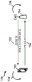
According to a second aspect of the disclosure, the base station may use a semi-persistent scheduling (SPS) type of DCI such that an ACK is expected based on successful decoding of the SPS type of DCI. In the case where the ACK/NACK response is used for both PDSCH and SPS type DCI decoding, if the UE does not successfully receive PDSCH, the UE may send NACK to the base station regardless of whether the SPS type DCI is successfully decoded. In a second aspect of the disclosure, the response to the SPS type of DCI is not associated with the response to the PDSCH. Thus, in the second aspect, although the UE may transmit an ACK/NACK response in response to the PDSCH, the UE may transmit a separate ACK/NACK response for decoding of the SPS-type DCI, where the separate ACK/NACK response is different from the ACK/NACK response in response to the PDSCH. For example, the UE transmits an ACK/NACK response in response to the PDSCH and also transmits a separate ACK/NACK response in response to the SPS type DCI. The SPS type DCI has a different bit pattern than other types of DCI. For example, when the UE decodes the PDDCH and detects a different bit pattern indicating a DCI of SPS type, the UE becomes aware that the UE should send a separate ACK/NACK response for the PDDCH carrying the DCI of SPS type independently of the PDSCH. Fig. 7B is an example diagram 730 illustrating a second aspect of the present disclosure. After the base station 704 determines to change the beam, the base station 704 transmits a PDCCH with a DCI of SPS type and may transmit a PDSCH at 732. At 734, the UE 702 attempts to decode the SPS-type DCI to detect the beam change instruction. At 736, the UE 702 sends an indication (e.g., a separate ACK/NACK) via PUCCH to indicate to the base station 704 whether a beam change instruction is detected, wherein the indication is a separate indication for a PDDCH carrying a DCI of SPS type. At 738, based on the indication from the UE 702, the base station 704 determines whether to change the beam. Because different SPS type DCI is used (for which separate ACK/NACK responses are transmitted), the ACK/NACK response for the CRC of the PDSCH does not interfere with the separate ACK/NACK response for the successful detection of the beam change instruction.
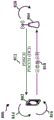
According to a third aspect of the present disclosure, when the base station communicates the beam change instruction using DCI for a downlink grant, when the DCI is decoded and the beam switch command is detected from the DCI, the UE may scramble the PUCCH transmitted to the base station with a different scrambling code that is different from the scrambling code used to scramble the PUCCH when the DCI is not decoded to detect the beam switch command. Fig. 7C is an example diagram 750 illustrating a third aspect of the present disclosure. After the base station 704 determines to change the beam, the base station 704 transmits a PDCCH with DCI and may transmit a PDSCH at 752. At 754, UE 702 attempts to decode the DCI to detect the beam change instruction. At 756, if the UE 702 successfully decodes the DCI detecting the beam change instruction, the UE scrambles the PUCCH with a different scrambling code to indicate the detection of the beam change instruction. At 758, the UE 702 transmits the scrambled PUCCH. At 760, based on the PUCCH received from UE 702 scrambled with a different scrambling code, base station 704 determines that a beam change instruction is detected and determines to change the beam. Since a different scrambling code is used when the beam switch command is detected, the PUCCH scrambled with the different scrambling code indicates the detection of the beam switch command to the base station. Accordingly, even if the UE simultaneously transmits NACKs for corresponding PDSCH transmissions, the base station may determine that the beam switching command is detected based on receiving a PUCCH scrambled with a different scrambling code. Accordingly, the base station may determine that the beam switch command is detected by detecting the PUCCH scrambled with the different scrambling code.
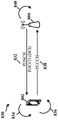
According to the fourth aspect of the present disclosure, when DCI is decoded and a beam switching command is detected from the DCI, the UE may include a different DMRS sequence in a PUCCH transmitted to the base station. The different DMRS sequence is different from a DMRS sequence used by the UE to transmit the PUCCH if no beam change instruction is detected in the DCI. Thus, by detecting different DMRS sequences in the PUCCH, the base station may determine that the beam switch command is detected. Fig. 7D is an example diagram 750 illustrating a fourth aspect of the present disclosure. After the base station 704 determines to change the beam, the base station 704 transmits a PDCCH with DCI and may transmit a PDSCH at 772. At 774, the UE attempts to decode the DCI to detect the beam change instruction. At 776, if the UE 702 successfully decodes the DCI to detect a beam change instruction, the UE includes a different DMRS sequence in the PUCCH to indicate that a beam change instruction was detected. At 778, the UE 702 transmits a PUCCH with a different DMRS sequence. At 780, based on the different DMRS sequences in the PUCCH received from UE 702, base station 704 determines that a beam change instruction is detected and determines to change the beam. Since the third and fourth aspects provide a specific indication that a beam switch command is detected, the ACK/NACK response to the CRC of the PDSCH does not interfere with the indication.
According to a fifth aspect of the disclosure, a UE may send a tri-state indicator (e.g., a tri-state ACK) to provide one of three indications. In an aspect, the tri-state indicator may be sent via PUCCH (e.g., via bits in PUCCH for the tri-state indicator). The first indication is to indicate that the DCI has been successfully decoded and the CRC for the PDSCH has failed. The second indication is to indicate that the DCI has been successfully decoded and the CRC for the PDSCH has passed. The third indication is used to indicate that the DCI has not been successfully decoded. Fig. 8A is an exemplary diagram 800 illustrating a fifth aspect of the present disclosure. After the base station 804 determines to change the beam, the base station 804 transmits a PDCCH with DCI and may transmit a PDSCH at 812. At 814, the UE 802 attempts to decode the DCI to detect the beam change instruction and perform CRC for the PDSCH. At 816, the UE 802 generates a tri-state indicator that includes one of the three indications discussed above. At 818, the UE 802 sends a tri-state indication. At 820, based on the tri-state indication, the base station 804 determines whether to change the beam. For example, when the tri-state indication provides the first indication or the second indication, the base station 804 may determine to change the beam because the first indication and the second indication are used to indicate that the DCI has been successfully decoded and a beam change instruction is detected. Since the tri-state indicator in the fifth aspect provides a specific indication for CRC pass/fail and successful decoding of DCI, the ACK/NACK response to the CRC of the PDSCH does not interfere with the tri-state indicator.
According to a sixth aspect of the present disclosure, the UE adds a part (e.g., bits) in the PUCCH to separately indicate ACK/NACK responses (and detection of a beam change instruction) for successful decoding of DCI, which are separate from ACK/NACK responses for the PDSCH. Fig. 8B is an example diagram 830 illustrating a sixth aspect of the present disclosure. After the base station 804 determines to change the beam, the base station 804 transmits a PDCCH with DCI and may transmit a PDSCH at 832. At 834, the UE 802 attempts to decode the DCI to detect the beam change instruction. At 836, the UE 802 includes bits in the PUCCH to individually indicate ACK/NACK responses for successful decoding of DCI and detection of beam change instructions. At 838, the UE 802 transmits the PUCCH with the bit. At 840, based on the bit included in the PUCCH, the base station 704 determines whether to change the beam. Since this aspect of the present disclosure indicates ACK/NACK responses for DCI with a separate part, ACK/NACK responses for CRC of PDSCH do not interfere with ACK/NACK responses for successful detection of beam change instructions.
According to a seventh aspect of the present disclosure, after transmitting DCI including a beam change instruction, a base station receives two or more sampling signals using two or more different beams, respectively. The base station may also multiply the same sample of an antenna element with two different antenna weights for receiving two different samples. At least one of the two or more different beams is indicated by a beam change instruction. The current beam may also be indicated in the beam change instruction. The base station receives the sampled signal in a subframe specified in the DCI. Based on the received sampled signals, the base station determines a condition (e.g., bandwidth) for each of the sampled signals and selects the beam corresponding to the sampled signal having the best condition (e.g., narrowest bandwidth). Fig. 8C is an example diagram 850 illustrating a sixth aspect of the present disclosure. After base station 804 determines to change the beam, base station 804 transmits the PDCCH with the DCI and may transmit the PDSCH at 852. At 854, the UE 802 decodes the DCI to detect the beam change instruction. At 856, the base station 804 receives the first sampled signal using the current beam. At 858, the base station 804 receives a second sampled signal using a second beam indicated by the beam change instruction. At 860, the base station 804 selects one of the current beam and the second beam based on the first sampled signal and the second sampled signal.
Fig. 9 is a flow chart 900 of a method of wireless communication in accordance with an aspect of the disclosure. The method may be performed by a base station (e.g., base station 704, base station 804, apparatus 1202/1202'). At 902, the base station determines to change from a first beam to a second beam. For example, as discussed above, when the UE indicates to the base station to change the beam of the base station, the base station may determine to change from the current beam to the second beam. In an aspect, the first beam and the second beam may be transmit beams or receive beams. At 904, the base station generates a beam change instruction indicating a determination to change from a first beam to a second beam. At 906, the base station sends a beam change instruction in DCI to the UE. For example, as discussed above, when the base station generates a beam change instruction for instructing the base station to change from a current beam to another beam, the base station transmits the beam change instruction to the UE in DCI. For example, as discussed above, the beam associated with the beam change instruction may be a transmit beam of the base station or a receive beam of the base station. In an aspect, the base station may transmit the beam change instruction by transmitting a PDCCH including DCI for an uplink grant or a downlink grant or transmitted via SPS. As shown in fig. 7A-7D, the base station 704 may transmit DCI for UL grant or DCI for DL grant via PDCCH, or may transmit SPS DCI. At 908, the base station determines whether a beam change instruction is detected by the UE. For example, as discussed above, the base station may determine whether the UE has detected a beam change instruction based on an indication from the UE.
In an aspect, the DCI is an SPS DCI. In an aspect, the SPS DCI is independent of the PDSCH. In an aspect, the SPS DCI has a different bit pattern than other DCIs. The SPS type DCI has a different bit pattern than other types of DCI. In an aspect, the base station determines whether the beam change instruction is detected by receiving an ACK from the UE indicating that the SPS DCI is received by the UE or a NACK indicating that the SPS DCI is not received by the UE. For example, as discussed above, when the UE decodes the PDDCH and detects a different bit pattern indicating a DCI of SPS type, the UE becomes aware that the UE should send a separate ACK/NACK response for the PDDCH carrying the DCI of SPS type independent of the PDSCH. For example, as shown in fig. 7B, at 736, the UE 702 sends an indication (e.g., a separate ACK/NACK) via PUCCH indicating to the base station 704 whether a beam change instruction is detected, wherein the indication is a separate indication for a PDDCH carrying a DCI of SPS type. For example, as shown in fig. 7B, the base station 704 determines whether to change the beam based on the indication from the UE 702 at 738.
In an aspect, the DCI is for a DL grant. In an aspect, the base station determines whether a beam change instruction is detected by receiving an indication that the beam change instruction is detected, wherein the determining whether the beam change instruction is detected is based on the indication. In such an aspect, the indication is received via a Physical Uplink Control Channel (PUCCH), the PUCCH being associated with DCI for the DL grant. For example, as shown in fig. 7B-7D and fig. 8B, UE 702 may send PUCCH with an indication that a beam change instruction was detected to base station 704. In an aspect, the indication may comprise a PUCCH scrambled with a beam change scrambling code, the beam change scrambling code indicating that the beam change instruction was detected by the UE. In such an aspect, if no beam change instruction is detected in the DCI, the beam change scrambling code is different from the scrambling code used by the UE to transmit the PUCCH. For example, as shown in fig. 7C, if the UE 702 successfully decodes the DCI to detect a beam change instruction at 756, the UE scrambles the PUCCH with a different scrambling code to indicate that a beam change instruction is detected, and the UE 702 transmits the scrambled PUCCH at 758. For example, as shown in fig. 7C, base station 704 determines that a beam change instruction is detected and determines to change the beam based on the PUCCH scrambled with the different scrambling code received from UE 702 at 760.
In another aspect, the indication may include a PUCCH containing a beam change DMRS sequence for indicating that the beam change instruction was detected by the UE. In such an aspect, if no beam change instruction is detected in the DCI, the beam change DMRS sequence is different from the DMRS sequence used by the UE to transmit the PUCCH. For example, as shown in fig. 7D, if the UE 702 successfully decodes the DCI to detect a beam change instruction at 776, the UE includes a different DMRS sequence in the PUCCH to indicate that the beam change instruction was detected, and at 778, the UE 702 transmits the PUCCH with the different DMRS sequence. For example, as shown in fig. 7D, at 780, based on the different DMRS sequence in the PUCCH received from the UE 702, the base station 704 determines that a beam change instruction is detected and determines to change the beam.
In another aspect, the indication includes a tri-state indicator indicating one of: successful decoding of DCI and failure of CRC for PDSCH when the DCI is successfully decoded and the CRC for PDSCH fails, successful decoding of DCI and passing of CRC for PDSCH when the DCI is successfully decoded and the CRC for PDSCH passes, and unsuccessful decoding of DCI when the DCI is not successfully decoded. As shown in fig. 8A, at 816, the UE 802 generates a tri-state indicator that includes one of three indications, which may include: a first indication that the DCI has been successfully decoded and the CRC for the PDSCH has failed, a second indication that the DCI has been successfully decoded and the CRC for the PDSCH has passed, and a third indication that the DCI has not been successfully decoded, and at 818, the UE 802 sends a tri-state indication.
In another aspect, the indication includes DCI bits included in the PUCCH to indicate whether the DCI was successfully decoded. For example, as shown in fig. 8B, at 836, the UE 802 includes bits in the PUCCH to individually indicate ACK/NACK responses for successful decoding of DCI and detection of beam change instructions, and at 838, the UE 802 transmits the PUCCH with the bits. For example, as shown in fig. 8B, the base station 704 determines whether to change the beam based on the bit included in the PUCCH at 840.
In an aspect, the DCI is transmitted for a UL grant. In an aspect, the base station determines whether a beam change instruction is detected by receiving an uplink transmission indicating that the UE has detected the beam change instruction and decoding the uplink transmission to determine whether the beam change instruction is detected. For example, as shown in fig. 7A, at 716, the UE 702 sends an indication via PUSCH indicating whether a beam change instruction is detected, and at 718, based on the indication from the UE 702, the base station 704 determines whether to change the beam (e.g., by decoding the indication). In an aspect, the base station also determines whether the beam change instruction is detected by the UE by receiving an uplink transmission indicating that the UE has detected the beam change instruction and detecting energy of the uplink transmission to determine whether the beam change instruction is detected. In such an aspect, the base station determines that the beam change instruction is detected if the energy of the detected uplink transmission is greater than an energy threshold. For example, as discussed above, if the energy of the DMRS is greater than the energy threshold, the base station may determine that the UE has successfully decoded DCI for the uplink grant and detected the beam change instruction. In another aspect, the base station also determines whether the beam change instruction is detected by the UE by receiving an uplink transmission indicating that the UE has detected the beam change instruction and decoding a DMRS included in the uplink transmission, the DMRS indicating that the beam change instruction was detected. For example, as discussed above, the base station may attempt to decode the DMRS for the PUSCH, where the DMRS indicates that the beam change instruction was detected by the UE.
At 910, upon determining that the UE detects a beam change instruction, the base station may change from a first beam to a second beam. For example, as discussed above, if the base station determines that a beam change instruction is detected by the UE, the base station may change from the current beam to another beam.
Fig. 10 is a flow chart 1000 of a method of wireless communication in accordance with an aspect of the disclosure. The method may be performed by a base station (e.g., base station 704, base station 804, apparatus 1202/1202'). At 1002, the base station transmits a beam change instruction in DCI using a first beam. At 1004, the base station receives a first sampled signal using a first beam. At 1006, the base station receives a second sampled signal using a second beam indicated by the beam change instruction. At 1008, the base station selects one of the first beam and the second beam based on the first sampled signal and the second sampled signal. In an aspect, the first sampled signal and the second sampled signal are received in a subframe designated to the UE in the DCI. For example, as shown in fig. 8C, at 856 the base station 804 receives a first sampled signal using the current beam, and at 858 the base station 804 receives a second sampled signal using a second beam indicated by the beam change instruction. For example, as shown in fig. 8C, at 860, the base station 804 selects one of the current beam and the second beam based on the first sampled signal and the second sampled signal.
Fig. 11 is a conceptual data flow diagram 1100 illustrating the data flow between different units/components in an exemplary apparatus 1102. The apparatus may be a base station. The apparatus comprises a receiving component 1104, a transmitting component 1106, a beam management component 1108, a beam change instruction component 1110, and a sample acquisition component 1112.
At 1162, beam management component 1108 determines to change from a first beam to a second beam and may signal beam change instruction component 1110 with the determination to change. The beam change instruction component 1110 generates a beam change instruction indicating a determination to change from a first beam to a second beam. At 1164 and 1162, beam change instruction component 1110 transmits the beam change instruction in DCI via transmitting component 1106 to a UE (e.g., UE 1140).
In an aspect, the DCI is an SPS DCI. In an aspect, the SPS DCI is independent of a Physical Downlink Shared Channel (PDSCH). In an aspect, the SPS DCI has a different bit pattern than other DCIs. In an aspect, the beam change instruction component 1110 determines whether the beam change instruction is detected by receiving an ACK from the UE indicating that SPS DCI was received by the UE 1040 or a NACK indicating that SPS DCI was not received by the UE 1040.
In an aspect, the DCI is for a DL grant. At 1168 and 1170, the beam change instruction component 1110 determines whether a beam change instruction is detected by receiving an indication from the UE 1140 via the receiving component 1104 that the beam change instruction was detected, wherein the determining whether the beam change instruction is detected is based on the indication. In an aspect, the indication is received via a PUCCH, which is associated with DCI for the DL grant. In an aspect, the indication may comprise a PUCCH scrambled with a beam change scrambling code, the beam change scrambling code indicating that the beam change instruction was detected by the UE. In such an aspect, if no beam change instruction is detected in the DCI, the beam change scrambling code is different from the scrambling code used by the UE to transmit the PUCCH. In another aspect, the indication may include a PUCCH containing a beam change DMRS sequence indicating that the beam change instruction was detected by the UE. In such an aspect, if no beam change instruction is detected in the DCI, the beam change DMRS sequence is different from the DMRS sequence used by the UE to transmit the PUCCH. In another aspect, the indication includes a tri-state indicator indicating one of: successful decoding of DCI and failure of Cyclic Redundancy Check (CRC) for PDSCH when the DCI is successfully decoded and fails, successful decoding of DCI and passing of CRC for PDSCH when the DCI is successfully decoded and the CRC for PDSCH passes, and unsuccessful decoding of DCI when the DCI is not successfully decoded. In another aspect, the indication includes DCI bits included in the PUCCH to indicate whether the DCI was successfully decoded.
At 1172, the beam change instruction component 1110 determines whether a beam change instruction was detected by the UE 1140 and may signal the determination to the beam management component 1108. Upon determining that a beam change instruction is detected by the UE, beam management component 1108 may change from a first beam to a second beam.
In an aspect, the DCI may be for an UL grant. In an aspect, the beam change instruction component 1110 further determines whether a beam change instruction is detected by the UE 1040 by receiving an uplink transmission via the receiving component 1104 indicating that the UE has detected the beam change instruction and decoding the uplink transmission to determine whether the beam change instruction is detected. In another aspect, the beam change instruction component 1110 further determines whether a beam change instruction is detected by receiving, via the receiving component 1104, an uplink transmission indicating that the UE has detected the beam change instruction and detecting an energy of the uplink transmission to determine whether the beam change instruction is detected. In such an aspect, beam change instruction component 1110 determines that a beam change instruction is detected if the energy of the detected uplink transmission is greater than an energy threshold. In another aspect, the beam change instruction component 1110 further determines whether a beam change instruction is detected by receiving, via the receiving component 1104, an uplink transmission indicating that the UE has detected the beam change instruction and decoding a DMRS included in the uplink transmission, the DMRS indicating that the beam change instruction was detected.
In an aspect, beam change instructing component 1110 transmits the beam change instruction via transmitting component 1106 by transmitting a PDCCH including DCI for an uplink grant or a downlink grant or transmitted via SPS.
The following is another method according to an aspect of the present disclosure. At 1164 and 1166, beam change instructing component 1110 transmits beam change instructions in the DCI (e.g., to UE 1140) using the first beam via transmitting component 1106. At 1168 and 1174, the sample acquisition component 1112 receives a first sampled signal using a first beam via the receive component 1104. At 1174, the sample acquisition component 1112 receives, via the receiving component 1104, a second sampled signal using a second beam indicated by the beam change instruction. At 1176, the sample acquisition component 1112 may forward information regarding the first and second sampled signals to the beam management component 1108. Beam management component 1108 selects one of the first beam and the second beam based on the first sampled signal and the second sampled signal. In an aspect, the first sampled signal and the second sampled signal are received in a subframe designated to the UE in the DCI.
The apparatus may include additional components to perform each of the blocks of the algorithms in the flowcharts of fig. 9 and 10 described above. Accordingly, each block in the flow diagrams of fig. 9 and 10 described above may be performed by a component, and the apparatus may include one or more of those components. These components may be one or more hardware components specifically configured to perform the processes/algorithms, implemented by a processor configured to perform the processes/algorithms, stored within a computer-readable medium to be implemented by a processor, or some combination thereof.
Fig. 12 is a diagram 1200 illustrating an example of a hardware implementation of an apparatus 1102' using a processing system 1214. The processing system 1214 may be implemented with a bus architecture, represented generally by the bus 1224. The bus 1224 may include any number of interconnecting buses and bridges depending on the specific application of the processing system 1214 and the overall design constraints. The bus 1224 couples various circuits together including one or more processor and/or hardware components represented by the processor 1204, the components 1104, 1106, 1108, 1110, 1112, and the computer-readable medium/memory 1206. The bus 1224 may also connect various other circuits such as timing sources, peripherals, voltage regulators, and power management circuits, which are well known in the art, and therefore, will not be described any further.
The processing system 1214 may be coupled to a transceiver 1210. The transceiver 1210 is coupled to one or more antennas 1220. The transceiver 1210 provides a means for communicating with various other apparatus over a transmission medium. The transceiver 1210 receives a signal from the one or more antennas 1220, extracts information from the received signal, and provides the extracted information to the processing system 1214 (in particular, the receiving component 1104). Further, the transceiver 1210 receives information from the processing system 1214 (and in particular the transmitting component 1106) and generates signals to be applied to the one or more antennas 1220 based on the received information. The processing system 1214 includes a processor 1204 coupled to a computer-readable medium/memory 1206. The processor 1204 is responsible for general processing, including the execution of software stored on the computer-readable medium/memory 1206. The software, when executed by the processor 1204, causes the processing system 1214 to perform the various functions described supra for any particular apparatus. The computer-readable medium/memory 1206 may also be used for storing data that is manipulated by the processor 1204 when executing software. The processing system 1214 also includes at least one of the components 1104, 1106, 1108, 1110, 1112. The components may be software components located/stored in the computer-readable medium/memory 1206 that run in the processor 1204, one or more hardware components coupled to the processor 1204, or some combination thereof. The processing system 1214 may be a component of the eNB 310 and may include the memory 376 and/or at least one of the following; TX processor 316, RX processor 370, and controller/processor 375.
In one configuration, the means for wireless communication 1102/1102' comprises: means for determining to change from a first beam to a second beam; means for generating a beam change instruction indicating a determination to change from a first beam to a second beam; means for transmitting a beam change instruction to the UE in the DCI; and means for determining whether the beam change instruction is detected by the UE. In an aspect, the apparatus 1102/1102' may further include: means for changing from a first beam to a second beam upon determining that the beam change instruction was detected by the UE.
In an aspect, the means for determining whether a beam change instruction is detected is configured to receive an uplink transmission indicating that the UE has detected the beam change instruction. In one aspect, the means for determining whether a beam change instruction is detected is further configured to: an uplink transmission indicating that the UE has detected the beam change instruction is received, and the uplink transmission is decoded to determine whether the beam change instruction is detected. In another aspect, the means for determining whether a beam change instruction is detected is further configured to: an uplink transmission indicating that the UE has detected the beam change instruction is received, and energy of the uplink transmission is detected to determine whether the beam change instruction is detected. In an aspect, the means for determining whether a beam change instruction is detected is configured to: determining that a beam change instruction is detected if the energy of the detected uplink transmission is greater than an energy threshold. In another aspect, the means for determining whether a beam change instruction is detected is further configured to: receiving an uplink transmission indicating that the UE has detected a beam change instruction and decoding a DMRS included in the uplink transmission, the DMRS indicating whether the beam change instruction was detected.
In an aspect, the means for determining whether a beam change instruction is detected is configured to: receiving, from the UE, an ACK indicating that the SPS DCI is received by the UE or a NACK indicating that the SPS DCI is not received by the UE, to determine whether the beam change instruction is detected. In an aspect, the means for transmitting the beam change instruction is configured to: transmitting a PDCCH including DCI for an uplink grant or a downlink grant or transmitted via SPS.
In an aspect, the means for determining whether a beam change instruction is detected may be configured to: receiving an indication that a beam change instruction is detected, wherein the determining whether a beam change instruction is detected is based on the indication.
In another configuration, the means for wireless communication 1102/1102' comprises: the apparatus includes means for transmitting a beam change instruction in DCI using a first beam, means for receiving a first sampled signal using the first beam, means for receiving a second sampled signal using a second beam indicated by the beam change instruction, and means for selecting one of the first beam and the second beam based on the first sampled signal and the second sampled signal.
The aforementioned means may be one or more of the aforementioned components of device 1102 and/or the processing system 1214 of device 1102' configured to perform the functions recited by the aforementioned means. As described supra, the processing system 1214 may include the TX processor 316, the RX processor 370, and the controller/processor 375. Thus, in one configuration, the means may be the TX processor 316, the RX processor 370, and the controller/processor 375 configured to perform the functions recited by the means.
Fig. 13 is a flow chart 1300 of a method of wireless communication. The method may be performed by a UE (e.g., UE 702, UE 802, apparatus 1402/1402'). At 1302, the UE receives DCI from a base station. At 1304, the UE determines whether a beam change instruction is detected in the DCI. At 1306, the UE indicates whether a beam change instruction is detected via an uplink transmission associated with the DCI, the uplink transmission comprising one of a PUCCH or a PUSCH. In an aspect, the PUCCH may include an ACK to indicate successful decoding of the DCI or a NACK to indicate unsuccessful decoding of the DCI. At 1308, the UE sends the uplink transmission to the base station. For example, as discussed above, when the base station generates a beam change instruction for instructing the base station to change from a current beam to another beam, the base station transmits the beam change instruction to the UE in DCI. For example, as discussed above, when the UE receives DCI from a base station, the UE decodes the DCI to attempt to detect a beam change instruction in the DCI. Subsequently, for example, as discussed above, the UE may indicate to the base station whether the UE has detected a beam change instruction, such that the base station may determine whether the UE has detected a beam change instruction based on the indication. For example, fig. 7A-7D show that PUCCH or PUSCH may be used to indicate whether a beam change instruction is detected by the UE.
In an aspect, the UE may receive the DCI by receiving at least one of: DCI for an uplink grant including a beam change instruction, DCI for a downlink grant including a beam change instruction, or SPS DCI including a beam change instruction. In such an aspect, upon receiving the SPS DCI grant, the UE may transmit an uplink transmission by transmitting an ACK indicating that a beam change instruction is detected or a NACK indicating that no beam change instruction is detected. In such an aspect, receiving at least one of DCI for an uplink grant, DIC for a downlink grant, or SPS DCI comprises: receiving a PDCCH comprising at least one of: DCI for an uplink grant, DCI for a downlink grant, or SPS DCI. In such an aspect, the SPS DCI is independent of the PDSCH. For example, as shown in fig. 7A, at 714, the UE 702 attempts to decode DCI for an uplink grant to detect a beam change instruction, and at 716, the UE 702 sends an indication via PUSCH indicating whether a beam change instruction is detected, and at 718, based on the indication from the UE 702. For example, as shown in fig. 7B, at 734, 702 attempts to decode the SPS type DCI to detect the beam change instruction, and at 736, the UE 702 sends an indication (e.g., a separate ACK/NACK) via PUCCH to indicate to the base station 704 whether the beam change instruction is detected, wherein the indication is a separate indication for the PDDCH carrying the SPS type DCI.
In an aspect, the UE indicates detection of the beam change instruction via an uplink transmission by scrambling the PUCCH with a beam change scrambling code, the beam change scrambling code indicating detection of the beam change instruction. In such an aspect, if no beam change instruction is detected in the DCI, the beam change scrambling code is different from the scrambling sequence used by the UE to transmit the PUCCH. For example, as shown in fig. 7C, if the UE 702 successfully decodes the DCI to detect a beam change instruction at 756, the UE scrambles the PUCCH with a different scrambling code to indicate that a beam change instruction is detected, and the UE 702 transmits the scrambled PUCCH at 758. For example, as discussed above, since a different scrambling code is used when a beam switch command is detected, a PUCCH scrambled with the different scrambling code indicates to the base station that the beam switch command is detected.
In an aspect, the UE indicates detection of a beam change instruction via uplink transmission by including a beam change DMRS sequence in the PUCCH indicating detection of the beam change instruction. In such an aspect, if no beam change instruction is detected in the DCI, the beam change DMRS sequence is different from the DMRS sequence used by the UE to transmit the PUCCH. For example, as shown in fig. 7D, if the UE 702 successfully decodes the DCI to detect a beam change instruction at 776, the UE includes a different DMRS sequence in the PUCCH to indicate that the beam change instruction was detected, and at 778, the UE 702 transmits the PUCCH with the different DMRS sequence. For example, as discussed above, if no beam change instruction is detected in the DCI, the different DMRS sequence is different from the DMRS sequence used by the UE to transmit the PUCCH.
In an aspect, the UE indicates detection of the beam change instruction via uplink transmission by including a tri-state indicator in the PUCCH to indicate one of: successful decoding of DCI and failure of CRC for PDSCH when the DCI is successfully decoded and the CRC for PDSCH fails, successful decoding of DCI and passing of CRC for PDSCH when the DCI is successfully decoded and the CRC for PDSCH passes, and unsuccessful decoding of DCI when the DCI is not successfully decoded. As shown in fig. 8A, at 816, the UE 802 generates a tri-state indicator that includes one of three indications, which may include: a first indication that the DCI has been successfully decoded and the CRC for the PDSCH has failed, a second indication that the DCI has been successfully decoded and the CRC for the PDSCH has passed, and a third indication that the DCI has not been successfully decoded, and at 818, the UE 802 sends a tri-state indication.
In an aspect, the UE indicates detection of the beam change instruction via an uplink transmission by including DCI bits in the PUCCH to indicate whether the DCI was successfully decoded. For example, as shown in fig. 8B, at 836, the UE 802 includes bits in the PUCCH to individually indicate ACK/NACK responses for successful decoding of DCI and detection of beam change instructions, and at 838, the UE 802 transmits the PUCCH with the bits.
Fig. 14 is a conceptual data flow diagram 1400 illustrating the data flow between different units/components in an exemplary apparatus 1402. The apparatus may be a UE. The apparatus comprises a receiving component 1404, a transmitting component 1406, and a DCI processing component 1408, an indication management component 1410, and a UL management component 1412.
At 1462 and 1464, DCI processing component 1408 receives DCI from a base station (e.g., base station 1450) via receiving component 1404. At 1466, DCI processing component 1408 determines whether a beam change instruction in DCI is detected, and may signal the determination to instruction management component 1414. At 1468, management component 1414 is instructed to indicate whether a beam change instruction is detected via an uplink transmission associated with the DCI, the uplink transmission including at least one of a PUCCH or a PUSCH, and the PUCCH can be conveyed to UL management component 1412. In an aspect, at 1470 and 1472, UL management component 1412 may send uplink transmissions to the base station via sending component 1406. In an aspect, the PUCCH includes an ACK to indicate successful decoding of the DCI or a NACK to indicate unsuccessful decoding of the DCI.
In an aspect, DCI processing component 1408 may receive DCI by receiving at least one of: DCI for an uplink grant including a beam change instruction, DCI for a downlink grant including a beam change instruction, or SPS DCI including a beam change instruction. In such an aspect, upon receiving an SPS DCI grant, at 1310, indication management component 1414 and UL management component 1412 may send an uplink transmission by sending an ACK indicating that a beam change instruction was detected or a NACK indicating that no beam change instruction was detected via sending component 1470. In such an aspect, receiving at least one of DCI for an uplink grant, DCI for a downlink grant, or SPS DCI comprises: receiving a PDCCH comprising at least one of: DCI for an uplink grant, DCI for a downlink grant, or SPS DCI. In such an aspect, the SPS DCI is independent of the PDSCH.
In an aspect, indication management component 1414 indicates detection of a beam change instruction via uplink transmission by scrambling PUCCH with a beam change scrambling code, which indicates detection of a beam change instruction. In such an aspect, if no beam change instruction is detected in the DCI, the beam change scrambling code is different from the scrambling sequence used by the UE to transmit the PUCCH.
In an aspect, indication management component 1414 indicates detection of a beam change instruction via uplink transmission by including a beam change DMRS sequence in PUCCH that indicates detection of a beam change instruction. In such an aspect, if no beam change instruction is detected in the DCI, the beam change DMRS sequence is different from the DMRS sequence used by the UE to transmit the PUCCH.
In an aspect, indication managing component 1414 indicates detection of a beam change instruction via an uplink transmission indication by including a tri-state indicator in a PUCCH to indicate one of: successful decoding of DCI and failure of CRC for PDSCH when the DCI is successfully decoded and the CRC for PDSCH fails, successful decoding of DCI and passing of CRC for PDSCH when the DCI is successfully decoded and the CRC for PDSCH passes, and unsuccessful decoding of DCI when the DCI is not successfully decoded.
In an aspect, indication management component 1414 indicates detection of a beam change instruction via uplink transmission by including DCI bits in the PUCCH to indicate whether the DCI was successfully decoded.
The apparatus may include additional components to perform each of the blocks of the algorithm in the flow chart of fig. 13 described above. Accordingly, each block in the flow chart of fig. 13 described above may be performed by a component, and the apparatus may include one or more of those components. These components may be one or more hardware components specifically configured to perform the processes/algorithms, implemented by a processor configured to perform the processes/algorithms, stored within a computer-readable medium to be implemented by a processor, or some combination thereof.
Fig. 15 is a diagram 1500 illustrating an example of a hardware implementation of an apparatus 1402' using a processing system 1514. The processing system 1514 may be implemented with a bus architecture, represented generally by the bus 1524. The bus 1524 may include any number of interconnecting buses and bridges depending on the specific application of the processing system 1514 and the overall design constraints. The bus 1524 connects together various circuits including one or more processors and/or hardware components represented by the processor 1504, the components 1404, 1406, 1408, 1410, 1412, and the computer-readable medium/memory 1506. The bus 1524 may also connect various other circuits such as timing sources, peripherals, voltage regulators, and power management circuits, which are well known in the art, and therefore, will not be described any further.
The processing system 1514 may be coupled to a transceiver 1510. The transceiver 1510 is coupled to one or more antennas 1520. The transceiver 1510 provides a means for communicating with various other apparatus over a transmission medium. The transceiver 1510 receives a signal from the one or more antennas 1520, extracts information from the received signal, and provides the extracted information to the processing system 1514 (specifically, the receiving component 1404). Further, the transceiver 1510 receives information from the processing system 1514 (and in particular, the transmitting component 1406) and generates signals to be applied to the one or more antennas 1520 based on the received information. The processing system 1514 includes a processor 1504 coupled to a computer-readable medium/memory 1506. The processor 1504 is responsible for general processing, including the execution of software stored on the computer-readable medium/memory 1506. The software, when executed by the processor 1504, causes the processing system 1514 to perform the various functions described supra for any particular apparatus. The computer-readable medium/memory 1506 may also be used for storing data that is manipulated by the processor 1504 when executing software. The processing system 1514 also includes at least one of the components 1404, 1406, 1408, 1410, 1412. The components may be software components located/stored in the computer-readable medium/memory 1506 to run in the processor 1504, one or more hardware components coupled to the processor 1504, or some combination thereof. The processing system 1514 may be a component of the UE 350 and may include the memory 360 and/or at least one of the following; TX processor 368, RX processor 356, and controller/processor 359.
In one configuration, the means for wireless communication 1402/1402' comprises: means for receiving DCI from a base station; means for determining whether a beam change instruction in DCI is detected; and means for indicating whether a beam change instruction is detected via an uplink transmission associated with the DCI, the uplink transmission comprising at least one of a PUCCH or a PUSCH; and means for transmitting the uplink transmission to the base station.
In an aspect, the means for indicating via an uplink transmission is configured to: the PUCCH is scrambled with a beam change scrambling code, which indicates that a beam change instruction is detected. In an aspect, the means for indicating via an uplink transmission is configured to: the DMRS sequences for beam changes are included in the PUCCH, indicating that a beam change instruction was detected. In an aspect, the means for indicating via an uplink transmission is configured to: including a tri-state indicator in the PUCCH to indicate one of: successful decoding of DCI and failure of CRC for PDSCH when the DCI is successfully decoded and the CRC for PDSCH fails, successful decoding of DCI and passing of CRC for PDSCH when the DCI is successfully decoded and the CRC for PDSCH passes, and unsuccessful decoding of DCI when the DCI is not successfully decoded. In an aspect, the means for indicating in the PUCCH is configured to: DCI bits are included in the PUCCH to indicate whether DCI is successfully decoded.
In an aspect, a means for receiving DCI includes: means for receiving at least one of: DCI for an uplink grant including a beam change instruction, DCI for a downlink grant including a beam change instruction, or SPS DCI including a beam change instruction. In such an aspect, the means for transmitting the uplink transmission may be configured to: when the SPSDCI grant is received, an ACK indicating that a beam change instruction is detected or a NACK indicating that no beam change instruction is detected is transmitted. In such an aspect, the means for receiving at least one of DCI for an uplink grant, DIC for a downlink grant, or SPS DCI is configured to: receiving a PDCCH comprising at least one of: DCI for an uplink grant, DCI for a downlink grant, or SPS DCI.
The aforementioned means may be one or more of the aforementioned components of the apparatus 1402 and/or the processing system 1514 of the apparatus 1402' configured to perform the functions recited by the aforementioned means. As described supra, the processing system 1514 may include the TX processor 368, the RX processor 356, and the controller/processor 359. Thus, in one configuration, the means may be the TX processor 368, the RX processor 356, and the controller/processor 359 configured to perform the functions recited by the means.
It should be understood that the specific order or hierarchy of blocks in the processes/flow diagrams disclosed is an illustration of exemplary approaches. It should be understood that the particular order or hierarchy of blocks in the processes/flow diagrams may be rearranged according to design preferences. Further, some blocks may be combined or omitted. The accompanying method claims present elements of the various blocks in a sample order, and are not meant to be limited to the specific order or hierarchy presented.
The previous description is provided to enable any person skilled in the art to practice the various aspects described herein. Various modifications to these aspects will be readily apparent to those skilled in the art, and the generic principles defined herein may be applied to other aspects. Thus, the claims are not intended to be limited to the aspects shown herein, but is to be accorded the full scope consistent with the language claims, wherein reference to an element in the singular is not intended to mean "one and only one" unless specifically so stated, but rather "one or more. The word "exemplary" is used herein to mean "serving as an example, instance, or illustration. Any aspect described herein as "exemplary" is not necessarily to be construed as preferred or advantageous over other aspects. The term "some" means one or more unless explicitly stated otherwise. Combinations such as "at least one of A, B or C", "one or more of A, B or C", "at least one of A, B and C", "one or more of A, B and C", and "A, B, C or any combination thereof" include any combination of A, B and/or C, and may include a plurality of a, B or C. In particular, combinations such as "at least one of A, B or C", "one or more of A, B or C", "at least one of A, B and C", "one or more of A, B and C", and "A, B, C or any combination thereof" may be a only, B only, C, A only and B, A and C, B and C, or a and B and C, wherein any such combination may include one or more members or some members of A, B or C. All structural and functional equivalents to the elements of the various aspects described throughout this disclosure that are known or later come to be known to those of ordinary skill in the art are expressly incorporated herein by reference and are intended to be encompassed by the claims. Moreover, nothing disclosed herein is intended to be dedicated to the public regardless of whether such disclosure is explicitly recited in the claims. The words "module," mechanism, "" element, "" device, "and the like may not be a substitute for the word" unit. Thus, no claim element is to be construed as a unit plus function unless the element is explicitly recited using the phrase "unit for … …".
Claims (97)
1. A method of wireless communication by a base station, comprising:
determining to change from a first beam to a second beam;
generating a beam change instruction indicating the determination to change from the first beam to the second beam;
transmitting the beam change instruction to a User Equipment (UE) in Downlink Control Information (DCI); and
determining whether the beam change instruction is detected by the UE,
wherein determining whether the beam change instruction is detected comprises: receiving an uplink transmission from the UE, the uplink transmission being associated with the DCI and indicating that the beam change instruction was received and that a data transmission was successfully received.
2. The method of claim 1, wherein the first beam and the second beam are transmit beams or receive beams.
3. The method of claim 1, further comprising:
changing from the first beam to the second beam upon determining that the beam change instruction is detected by the UE.
4. The method of claim 1, wherein the DCI is transmitted for a downlink DL grant.
5. The method of claim 1, wherein the DCI is an SPSDCI transmitted via semi-persistent scheduling (SPS).
6. The method of claim 5, wherein the SPSDCI is independent of a Physical Downlink Shared Channel (PDSCH).
7. The method of claim 5, wherein the SPSDCI has a different bit pattern than other DCIs.
8. The method of claim 5, wherein the determining whether the beam change instruction is detected comprises:
receiving an acknowledgement ACK from the UE indicating that the SPSDCI was received by the UE.
9. The method of claim 1, wherein the uplink transmission comprises a beam change scrambling code indicating that the beam change instruction was detected by the UE.
10. The method of claim 1, wherein the transmitting the beam change instruction comprises:
transmitting a physical downlink control channel, PDCCH, including the DCI for an uplink grant or for a downlink grant or transmitted via a semi-persistent scheduling, SPS.
11. The method of claim 1, wherein the determining whether the beam change instruction is detected comprises:
receiving an indication in the uplink transmission that the beam change instruction was detected,
wherein the determining whether the beam change instruction is detected is based on the indication.
12. The method of claim 11, wherein the indication is received via a Physical Uplink Control Channel (PUCCH) associated with the DCI for a DL grant.
13. The method of claim 12, wherein the indication comprises:
the PUCCH scrambled with a beam change scrambling code indicating that the beam change instruction was detected by the UE.
14. The method of claim 13, wherein, if the beam change instruction is not detected in the DCI, the beam change scrambling code is different from a scrambling code used by the UE to transmit a PUCCH.
15. The method of claim 12, wherein the indication comprises:
the PUCCH that includes a beam change demodulation reference signal (DMRS) sequence that indicates that the beam change instruction was detected by the UE.
16. The method of claim 15, wherein, if the beam change instruction is not detected in the DCI, the beam change DMRS sequence is different from a DMRS sequence used by the UE to transmit PUCCH.
17. The method of claim 12, wherein the indication comprises:
DCI bits included in the PUCCH to indicate whether the DCI is successfully decoded.
18. The method of claim 11, wherein the indication comprises a tri-state indicator indicating one of:
when the DCI is successfully decoded and a cyclic redundancy check, CRC, for a physical downlink shared channel, PDSCH fails, the successful decoding of the DCI and the CRC for the PDSCH fails,
when the DCI is successfully decoded and the CRC for the PDSCH passes, the successful decoding of the DCI and the CRC for the PDSCH passes, and
unsuccessful decoding of the DCI when the DCI is not successfully decoded.
19. A method of wireless communication by a user equipment, UE, comprising:
receiving downlink control information, DCI, from a base station;
determining that a beam change instruction is detected in the DCI;
indicating, via an uplink transmission associated with the DCI, that the beam change instruction was detected and that a data transmission was successfully received, the uplink transmission comprising at least one of a physical uplink control channel, PUCCH, or a physical uplink shared channel, PUSCH; and
transmitting the uplink transmission to the base station,
wherein the uplink transmission is detected based on the beam change instruction.
20. The method of claim 19, wherein the uplink transmission comprises an Acknowledgement (ACK) indicating successful decoding of the DCI.
21. The method of claim 19, wherein the uplink transmission comprises a beam change scrambling code indicating that the beam change instruction was detected.
22. The method of claim 19, wherein the indicating via the uplink transmission comprises:
scrambling the PUCCH with a beam change scrambling code indicating that the beam change instruction is detected.
23. The method of claim 22, wherein, if the beam change instruction is not detected in the DCI, the beam change scrambling code is different from a scrambling sequence used by the UE to transmit a PUCCH.
24. The method of claim 19, wherein the indicating via the uplink transmission comprises:
including a beam change demodulation reference signal, DMRS, sequence in the PUCCH indicating that the beam change instruction was detected.
25. The method of claim 24, wherein, if the beam change instruction is not detected in the DCI, the beam change DMRS sequence is different from a DMRS sequence used by the UE to transmit PUCCH.
26. The method of claim 19, wherein the indicating via the uplink transmission comprises including a tri-state indicator in the uplink transmission to indicate one of:
when the DCI is successfully decoded and a cyclic redundancy check, CRC, for a physical downlink shared channel, PDSCH, fails, the successful decoding of the DCI and the CRC for the PDSCH fails;
when the DCI is successfully decoded and the CRC for the PDSCH passes, the successful decoding of the DCI and the CRC for the PDSCH passes, and
unsuccessful decoding of the DCI when the DCI is not successfully decoded.
27. The method of claim 19, wherein the indicating via the uplink transmission comprises:
including DCI bits in the PUCCH to indicate whether the DCI was successfully decoded.
28. The method of claim 19, wherein the receiving the DCI comprises:
receiving at least one of: DCI for an uplink grant including the beam change instruction, DCI for a downlink grant including the beam change instruction, or a semi-persistent scheduling, SPSDCI, including the beam change instruction.
29. The method of claim 28, wherein indicating via the uplink transmission comprises:
transmitting an acknowledgement ACK indicating that the beam change instruction is detected.
30. The method of claim 28, wherein the receiving at least one of the DCI for the uplink grant, the DCI for the downlink grant, or the SPSDCI comprises:
receiving a physical downlink control channel, PDCCH, comprising at least one of: the DCI for an uplink grant, the DCI for a downlink grant, or the SPS DCI.
31. The method of claim 29, wherein the SPSDCI is independent of a Physical Downlink Shared Channel (PDSCH).
32. A base station for wireless communication, comprising:
means for determining to change from a first beam to a second beam;
means for generating a beam change instruction indicating the determination to change from the first beam to the second beam;
means for transmitting the beam change instruction to a user equipment, UE, in downlink control information, DCI; and
means for determining whether the beam change instruction is detected by the UE,
wherein the means for determining whether the beam change instruction is detected is further configured to: receiving an uplink transmission from the UE, the uplink transmission being associated with the DCI and indicating that the beam change instruction was received and that a data transmission was successfully received.
33. The base station of claim 32, wherein the first beam and the second beam are transmit beams or receive beams.
34. The base station of claim 32, further comprising:
means for changing from the first beam to the second beam upon determining that the beam change instruction is detected by the UE.
35. The base station of claim 32, wherein the DCI is transmitted for a downlink DL grant.
36. The base station of claim 32, wherein the DCI is an SPSDCI transmitted via semi-persistent scheduling, SPS.
37. The base station of claim 36, wherein the SPSDCI is independent of a Physical Downlink Shared Channel (PDSCH).
38. The base station of claim 36, wherein the SPSDCI has a different bit pattern than other DCIs.
39. The base station of claim 32, wherein the uplink transmission comprises a beam change scrambling code indicating that the beam change instruction was detected by the UE.
40. The base station of claim 36, wherein the means for determining whether the beam change instruction is detected is configured to:
receiving an acknowledgement ACK from the UE indicating that the SPSDCI was received by the UE.
41. The base station of claim 32, wherein the means for transmitting the beam change instruction is configured to:
transmitting a Physical Downlink Control Channel (PDCCH) including the DCI for an uplink grant or a downlink grant or transmitted via semi-persistent scheduling (SPS).
42. The base station of claim 32, wherein the means for determining whether the beam change instruction is detected is configured to:
receiving an indication in the uplink transmission that the beam change instruction was detected,
wherein the determining whether the beam change instruction is detected is based on the indication.
43. The base station of claim 42, wherein the indication is received via a Physical Uplink Control Channel (PUCCH) associated with the DCI for a DL grant.
44. The base station of claim 43, wherein the indication comprises:
the PUCCH scrambled with a beam change scrambling code indicating that the beam change instruction was detected by the UE.
45. The base station of claim 44, wherein, if the beam change instruction is not detected in the DCI, the beam change scrambling code is different from a scrambling code used by the UE to transmit PUCCH.
46. The base station of claim 43, wherein the indication comprises:
the PUCCH that includes a beam change demodulation reference signal (DMRS) sequence that indicates that the beam change instruction was detected by the UE.
47. The base station of claim 46, wherein, if the beam change instruction is not detected in the DCI, the beam change DMRS sequence is different from a DMRS sequence used by the UE to transmit PUCCH.
48. The base station of claim 43, wherein the indication comprises:
DCI bits included in the PUCCH to indicate whether the DCI is successfully decoded.
49. The base station of claim 42, wherein the indication comprises a tri-state indicator indicating one of:
when the DCI is successfully decoded and a cyclic redundancy check, CRC, for a physical downlink shared channel, PDSCH fails, a successful decoding of the DCI and a failure of the CRC for the PDSCH,
when the DCI is successfully decoded and the CRC for the PDSCH passes, the successful decoding of the DCI and the passing of the CRC for the PDSCH, and
unsuccessful decoding of the DCI when the DCI is not successfully decoded.
50. A user equipment, UE, for wireless communication, comprising:
means for receiving downlink control information, DCI, from a base station;
means for determining that a beam change instruction is detected in the DCI;
means for indicating, via an uplink transmission associated with the DCI, that the beam change instruction was detected and a data transmission was successfully received, the uplink transmission comprising at least one of a physical uplink control channel, PUCCH, or a physical uplink shared channel, PUSCH; and
means for transmitting the uplink transmission to the base station,
wherein the uplink transmission is detected based on the beam change instruction.
51. The UE of claim 50, wherein the uplink transmission comprises an Acknowledgement (ACK) indicating successful decoding of the DCI.
52. The UE of claim 50, wherein the uplink transmission comprises a beam change scrambling code indicating that the beam change instruction was detected.
53. The UE of claim 50, wherein the means for indicating via the uplink transmission is configured to:
scrambling the PUCCH with a beam change scrambling code indicating that the beam change instruction is detected.
54. The UE of claim 53, wherein, if the beam change instruction is not detected in the DCI, the beam change scrambling code is different from a scrambling sequence used by the UE to transmit PUCCH.
55. The UE of claim 50, wherein the means for indicating via the uplink transmission is configured to:
including a beam change demodulation reference signal, DMRS, sequence in the PUCCH indicating that the beam change instruction was detected.
56. The UE of claim 55, wherein, if the beam change instruction is not detected in the DCI, the beam change DMRS sequence is different from a DMRS sequence used by the UE to transmit PUCCH.
57. The UE of claim 50, wherein the means for indicating via the uplink transmission is configured to include a tri-state indicator in the uplink transmission to indicate one of:
when the DCI is successfully decoded and a cyclic redundancy check, CRC, for a physical downlink shared channel, PDSCH, fails, the successful decoding of the DCI and the CRC for the PDSCH fails;
when the DCI is successfully decoded and the CRC for the PDSCH passes, the successful decoding of the DCI and the CRC for the PDSCH passes, and
unsuccessful decoding of the DCI when the DCI is not successfully decoded.
58. The UE of claim 50, wherein the means for indicating via the uplink transmission is configured to:
including DCI bits in the PUCCH to indicate whether the DCI was successfully decoded.
59. The UE of claim 50, wherein the means for receiving the DCI comprises:
means for receiving at least one of: a DCI for an uplink grant including the beam change instruction without using the DCI for a downlink grant, a DCI for a downlink grant including the beam change instruction, or a semi-persistent scheduling (SPSDCI) including the beam change instruction.
60. The UE of claim 59, wherein the means for indicating via the uplink transmission is configured to:
transmitting an acknowledgement ACK indicating that the beam change instruction is detected.
61. The UE of claim 59, wherein the means for receiving at least one of the DCI for the uplink grant, the DCI for the downlink grant, or the SPSDCI is configured to:
receiving a physical downlink control channel, PDCCH, comprising at least one of: the DCI for an uplink grant, the DCI for a downlink grant, or the SPS DCI.
62. The UE of claim 60, wherein the SPSDCI is independent of a Physical Downlink Shared Channel (PDSCH).
63. A base station for wireless communication, comprising:
a memory; and
at least one processor coupled to the memory and configured to:
determining to change from a first beam to a second beam;
generating a beam change instruction indicating the determination to change from the first beam to the second beam;
transmitting the beam change instruction to a User Equipment (UE) in Downlink Control Information (DCI); and
determining whether the beam change instruction is detected by the UE,
wherein the at least one processor configured to determine whether the beam change instruction is detected is further configured to: receiving an uplink transmission from the UE, the uplink transmission being associated with the DCI and indicating that the beam change instruction was received and that a data transmission was successfully received.
64. The base station of claim 63, wherein the first beam and the second beam are transmit beams or receive beams.
65. The base station of claim 63, wherein the at least one processor is further configured to:
changing from the first beam to the second beam upon determining that the beam change instruction is detected by the UE.
66. The base station of claim 63, wherein the DCI is transmitted for a Downlink (DL) grant.
67. The base station of claim 63, wherein the DCI is an SPSDCI transmitted via semi-persistent scheduling (SPS).
68. The base station of claim 67, wherein the SPSDCI is independent of a Physical Downlink Shared Channel (PDSCH).
69. The base station of claim 67, wherein the SPSDCI has a different bit pattern than other DCIs.
70. The base station of claim 63, wherein the uplink transmission comprises a beam change scrambling code indicating that the beam change instruction was detected by the UE.
71. The base station of claim 67, wherein the at least one processor configured to determine whether the beam change instruction is detected is configured to:
receiving an acknowledgement ACK from the UE indicating that the SPSDCI was received by the UE.
72. The base station of claim 63, wherein the at least one processor configured to transmit the beam change instruction is configured to:
transmitting a Physical Downlink Control Channel (PDCCH) including the DCI for an uplink grant or a downlink grant or transmitted via semi-persistent scheduling (SPS).
73. The base station of claim 63, wherein the at least one processor configured to determine whether the beam change instruction is detected is configured to:
receiving an indication in the uplink transmission that the beam change instruction was detected,
wherein the determining whether the beam change instruction is detected is based on the indication.
74. The base station of claim 73, wherein the indication is received via a Physical Uplink Control Channel (PUCCH) associated with the DCI for a DL grant.
75. The base station of claim 74, wherein the indication comprises:
the PUCCH scrambled with a beam change scrambling code indicating that the beam change instruction was detected by the UE.
76. The base station of claim 75, wherein, if the beam change instruction is not detected in the DCI, the beam change scrambling code is different from a scrambling code used by the UE to transmit PUCCH.
77. The base station of claim 74, wherein the indication comprises:
the PUCCH that includes a beam change demodulation reference signal (DMRS) sequence that indicates that the beam change instruction was detected by the UE.
78. The base station of claim 77, wherein, if the beam change instruction is not detected in the DCI, the beam change DMRS sequence is different from a DMRS sequence used by the UE to transmit PUCCH.
79. The base station of claim 74, wherein the indication comprises:
DCI bits included in the PUCCH to indicate whether the DCI is successfully decoded.
80. The base station of claim 73, wherein the indication comprises a tri-state indicator indicating one of:
when the DCI is successfully decoded and a cyclic redundancy check, CRC, for a physical downlink shared channel, PDSCH fails, the successful decoding of the DCI and the CRC for the PDSCH fails,
when the DCI is successfully decoded and the CRC for the PDSCH passes, the successful decoding of the DCI and the CRC for the PDSCH passes, and
unsuccessful decoding of the DCI when the DCI is not successfully decoded.
81. A user equipment, UE, for wireless communication, comprising:
a memory; and
at least one processor coupled to the memory and configured to:
receiving downlink control information, DCI, from a base station;
determining that a beam change instruction is detected in the DCI;
indicating, via an uplink transmission associated with the DCI, that the beam change instruction was detected and that a data transmission was successfully received, the uplink transmission comprising at least one of a physical uplink control channel, PUCCH, or a physical uplink shared channel, PUSCH; and
transmitting the uplink transmission to the base station,
wherein the uplink transmission is detected based on the beam change instruction.
82. The UE of claim 81, wherein the uplink transmission comprises an Acknowledgement (ACK) indicating successful decoding of the DCI.
83. The UE of claim 81, wherein the uplink transmission comprises a beam change scrambling code indicating that the beam change instruction was detected.
84. The UE of claim 81, wherein the at least one processor configured to indicate in the PUCCH is configured to:
scrambling the PUCCH with a beam change scrambling code indicating that the beam change instruction is detected.
85. The UE of claim 84, wherein, if the beam change instruction is not detected in the DCI, the beam change scrambling code is different from a scrambling sequence used by the UE to transmit the PUCCH.
86. The UE of claim 81, wherein the at least one processor configured to indicate in the PUCCH is configured to:
including a beam change demodulation reference signal, DMRS, sequence in the PUCCH indicating that the beam change instruction was detected.
87. The UE of claim 86, wherein, if the beam change instruction is not detected in the DCI, the beam change DMRS sequence is different from a DMRS sequence used by the UE to transmit PUCCH.
88. The UE of claim 81, wherein the at least one processor configured to indicate in the PUCCH is configured to include a tri-state indicator in the PUCCH to indicate one of:
when the DCI is successfully decoded and a cyclic redundancy check, CRC, for a physical downlink shared channel, PDSCH fails, the successful decoding of the DCI and the CRC for the PDSCH fails,
when the DCI is successfully decoded and the CRC for the PDSCH passes, the successful decoding of the DCI and the CRC for the PDSCH passes, and
unsuccessful decoding of the DCI when the DCI is not successfully decoded.
89. The UE of claim 81, wherein the at least one processor configured to indicate in the PUCCH is configured to:
including DCI bits in the PUCCH to indicate whether the DCI was successfully decoded.
90. The UE of claim 81, wherein the at least one processor configured to receive the DCI is configured to:
receiving at least one of: a DCI for an uplink grant including the beam change instruction without using the DCI for a downlink grant, or a semi-persistent scheduling SPSDCI including the beam change instruction.
91. The UE of claim 90, wherein the at least one processor configured to indicate via the uplink transmission is configured to:
transmitting an acknowledgement ACK indicating that the beam change instruction is detected.
92. The UE of claim 90, wherein the at least one processor configured to receive at least one of the DCI for the uplink grant, the DCI for the downlink grant, or the spdci is configured to:
receiving a physical downlink control channel, PDCCH, comprising at least one of: the DCI or the SPSDCI for an uplink grant.
93. The UE of claim 91, wherein the SPSDCI is independent of a Physical Downlink Shared Channel (PDSCH).
94. A non-transitory computer-readable medium storing computer executable code for a base station, comprising code to:
determining to change from a first beam to a second beam;
generating a beam change instruction indicating the determination to change from the first beam to the second beam;
transmitting the beam change instruction to a User Equipment (UE) in Downlink Control Information (DCI); and
determining whether the beam change instruction is detected by the UE,
wherein the code for determining whether the beam change instruction is detected further comprises code for: receiving an uplink transmission from the UE, the uplink transmission being associated with the DCI and indicating that the beam change instruction was received and that a data transmission was successfully received.
95. The non-transitory computer-readable medium of claim 94, wherein the uplink transmission comprises a beam change scrambling code indicating that the beam change instruction was detected by the UE.
96. A non-transitory computer-readable medium storing computer executable code for a user equipment, UE, comprising code to:
receiving downlink control information, DCI, from a base station;
determining that a beam change instruction is detected in the DCI;
indicating, via an uplink transmission associated with the DCI, that the beam change instruction was detected and that a data transmission was successfully received, the uplink transmission comprising at least one of a physical uplink control channel, PUCCH, or a physical uplink shared channel, PUSCH; and
transmitting the uplink transmission to the base station,
wherein the uplink transmission is detected based on the beam change instruction.
97. The non-transitory computer-readable medium of claim 96, wherein the uplink transmission comprises a beam change scrambling code indicating that the beam change instruction was detected.
Applications Claiming Priority (5)
| Application Number | Priority Date | Filing Date | Title |
|---|---|---|---|
| US201662348829P | 2016-06-10 | 2016-06-10 | |
| US62/348,829 | 2016-06-10 | ||
| US15/400,446 | 2017-01-06 | ||
| US15/400,446 US10687335B2 (en) | 2016-06-10 | 2017-01-06 | Informing base station regarding user equipment's reception of beam change instruction |
| PCT/US2017/032693 WO2017213806A1 (en) | 2016-06-10 | 2017-05-15 | Informing base station regarding user equipment's reception of beam change instruction |
Publications (2)
| Publication Number | Publication Date |
|---|---|
| CN109155662A CN109155662A (en) | 2019-01-04 |
| CN109155662B true CN109155662B (en) | 2022-01-04 |
Family
ID=60573471
Family Applications (1)
| Application Number | Title | Priority Date | Filing Date |
|---|---|---|---|
| CN201780030805.2A Active CN109155662B (en) | 2016-06-10 | 2017-05-15 | Informing a base station about reception of a beam change instruction by a user equipment |
Country Status (9)
| Country | Link |
|---|---|
| US (2) | US10687335B2 (en) |
| EP (1) | EP3469729A1 (en) |
| CN (1) | CN109155662B (en) |
| AU (1) | AU2017278673B2 (en) |
| BR (1) | BR112018074888A2 (en) |
| CA (1) | CA3021997A1 (en) |
| SG (1) | SG11201809123UA (en) |
| TW (1) | TWI729132B (en) |
| WO (1) | WO2017213806A1 (en) |
Families Citing this family (53)
| Publication number | Priority date | Publication date | Assignee | Title |
|---|---|---|---|---|
| CN111030743B (en) * | 2015-09-11 | 2023-08-11 | 苹果公司 | Reference signal for initial acquisition in 5G system |
| US10349404B2 (en) * | 2016-04-22 | 2019-07-09 | Qualcomm Incorporated | Discovery reference signal transmission and decoding and measurement techniques in a wireless communication system |
| US10687335B2 (en) | 2016-06-10 | 2020-06-16 | Qualcomm Incorporated | Informing base station regarding user equipment's reception of beam change instruction |
| WO2017221202A1 (en) * | 2016-06-23 | 2017-12-28 | Nokia Technologies Oy | Beam change |
| US11451976B2 (en) * | 2016-06-24 | 2022-09-20 | Asustek Computer Inc. | Method and apparatus for performing UE beamforming in a wireless communication system |
| US10517021B2 (en) | 2016-06-30 | 2019-12-24 | Evolve Cellular Inc. | Long term evolution-primary WiFi (LTE-PW) |
| US10999745B2 (en) * | 2017-01-06 | 2021-05-04 | Lg Electronics Inc. | Method and device for transmitting or receiving wireless signal in wireless communication system |
| US10499390B2 (en) * | 2017-03-24 | 2019-12-03 | Institute For Information Industry | Base station, user equipment, transmission control method for base station and data transmission method for user equipment |
| WO2018172896A1 (en) | 2017-03-24 | 2018-09-27 | Telefonaktiebolaget Lm Ericsson (Publ) | Uplink harq-ack feedback for mtc |
| CN109309550B (en) * | 2017-07-26 | 2021-10-29 | 维沃移动通信有限公司 | BWP control method, related equipment and system |
| US10686506B2 (en) | 2017-08-04 | 2020-06-16 | Qualcomm Incorporated | Subset based spatial quasi-colocation parameter indication using multiple beams |
| CN109391948B (en) | 2017-08-09 | 2022-04-08 | 维沃移动通信有限公司 | Processing method of beam indication, mobile terminal and network side equipment |
| KR102439591B1 (en) * | 2017-08-23 | 2022-09-02 | 삼성전자주식회사 | Apparatus and method for beam management in wireless communication system |
| US10965360B2 (en) * | 2017-08-23 | 2021-03-30 | Qualcomm Incorporated | Methods and apparatus related to beam refinement |
| US10567064B2 (en) * | 2017-09-08 | 2020-02-18 | At&T Intellectual Property I, L.P. | Beam recovery for partial control channel failure |
| US10123322B1 (en) * | 2017-09-18 | 2018-11-06 | Qualcomm Incorporated | Transmission of beam switch commands through control channel signaling |
| JP7203104B2 (en) * | 2017-11-14 | 2023-01-12 | テレフオンアクチーボラゲット エルエム エリクソン(パブル) | Acknowledgment signaling process for radio access networks |
| CN108093481B (en) * | 2017-11-28 | 2023-04-18 | 中兴通讯股份有限公司 | Method and device for transmitting beam recovery information, and beam detection method and device |
| CN110022611B (en) * | 2018-01-10 | 2022-10-28 | 展讯通信(上海)有限公司 | Method and device for realizing beam failure recovery and user equipment |
| CN110034799B (en) * | 2018-01-11 | 2023-09-01 | 华为技术有限公司 | Communication method and communication device |
| WO2019138555A1 (en) * | 2018-01-12 | 2019-07-18 | 株式会社Nttドコモ | User terminal and wireless communication method |
| IT201800000832A1 (en) * | 2018-01-12 | 2019-07-12 | Inst Rundfunktechnik Gmbh | SENDER UND / ODER EMPFÄNGER ZUM SENDEN BZW. EMPFANGEN VON RUNDFUNKINFORMATIONSSIGNALEN |
| US11272576B2 (en) * | 2018-02-15 | 2022-03-08 | Apple Inc. | Hierarchical beamforming structure and transmission of beam indication to improve device mobility and reduce network traffic overhead in new radio (NR) |
| US11057166B2 (en) * | 2018-02-16 | 2021-07-06 | Qualcomm Incorporated | Virtual search spaces for beam indication |
| US11088750B2 (en) * | 2018-02-16 | 2021-08-10 | Qualcomm Incorporated | Feedback of beam switch time capability |
| US10944455B2 (en) * | 2018-02-26 | 2021-03-09 | Qualcomm Incorporated | Beam tracking for periodic user equipment movement |
| CN110351112B (en) * | 2018-03-27 | 2023-08-08 | 苹果公司 | Apparatus and method for beam fault detection in new air interface |
| US11251847B2 (en) * | 2018-03-28 | 2022-02-15 | Google Llc | User device beamforming |
| US11109380B2 (en) * | 2018-04-05 | 2021-08-31 | Qualcomm Incorporated | Uplink control channel beam switch procedure |
| GB2573817B (en) * | 2018-05-18 | 2020-12-02 | Cambium Networks Ltd | Method and Apparatus for Interference Mitigation for a MU-MIMO wireless Communication network |
| CN110545129B (en) * | 2018-05-29 | 2021-01-29 | 华为技术有限公司 | Beam transmission method, device and system |
| CN112740566A (en) * | 2018-07-27 | 2021-04-30 | 株式会社Ntt都科摩 | Base station and wireless communication method |
| US10848222B2 (en) * | 2018-09-28 | 2020-11-24 | Qualcomm Incorporated | Synchronizing timing for updating beam configuration information |
| WO2020091681A1 (en) * | 2018-11-02 | 2020-05-07 | Telefonaktiebolaget Lm Ericsson (Publ) | Energy detection indicator |
| US11349543B2 (en) * | 2018-11-16 | 2022-05-31 | Qualcomm Incorporated | Beam switch count in beamformed wireless communications |
| US10736120B1 (en) * | 2018-12-19 | 2020-08-04 | Sprint Spectrum L.P. | Controlling base station selection based on minimum service-beam beamwidth capability |
| CN111447681B (en) * | 2019-01-17 | 2023-03-28 | 中国移动通信有限公司研究院 | Beam recovery method, device, medium and equipment |
| US11483807B2 (en) * | 2019-02-13 | 2022-10-25 | Qualcomm Incorporated | Beam training request techniques in beamformed wireless communications |
| CN114845398A (en) * | 2019-03-28 | 2022-08-02 | 华为技术有限公司 | Method and communication device for updating beam |
| US11159225B2 (en) * | 2019-05-01 | 2021-10-26 | Qualcomm Incorporated | Control for multi-panel UE activation/deactivation |
| US11381298B2 (en) * | 2019-06-28 | 2022-07-05 | Qualcomm Incorporated | User equipment based beam measurement resource activation |
| US11700599B2 (en) * | 2019-10-10 | 2023-07-11 | Qualcomm Incorporated | Beam switching gap |
| CN110971384A (en) * | 2019-11-15 | 2020-04-07 | 深圳职业技术学院 | Terminal-assisted information transmission method |
| US11575488B2 (en) * | 2019-12-13 | 2023-02-07 | Qualcomm Incorporated | Coverage enhancement for a beam change acknowledgement |
| US20210234597A1 (en) * | 2020-01-27 | 2021-07-29 | Qualcomm Incorporated | Asymmetric uplink-downlink beam training in frequency bands |
| US11856570B2 (en) | 2020-01-27 | 2023-12-26 | Qualcomm Incorporated | Dynamic mixed mode beam correspondence in upper millimeter wave bands |
| US11831383B2 (en) | 2020-01-27 | 2023-11-28 | Qualcomm Incorporated | Beam failure recovery assistance in upper band millimeter wave wireless communications |
| US20210360433A1 (en) * | 2020-05-13 | 2021-11-18 | Qualcomm Incorporated | Beam switching in a time domain |
| CN116648955A (en) * | 2020-10-19 | 2023-08-25 | 上海诺基亚贝尔股份有限公司 | Mechanism for beam shaping coordination |
| US11784758B2 (en) * | 2021-02-18 | 2023-10-10 | Qualcomm Incorporated | Hybrid automatic repeat request (HARQ) procedure using multiple beams in a wireless wide area network (WWAN) |
| BR112023023282A2 (en) * | 2021-05-07 | 2024-01-23 | Beijing Xiaomi Mobile Software Co Ltd | METHOD, APPARATUS AND FEEDBACK DEVICE, AND, STORAGE INSTRUCTIONS STORED WITH INSTRUCTIONS |
| WO2023010544A1 (en) * | 2021-08-06 | 2023-02-09 | Qualcomm Incorporated | Confirmation to implicit beam switch |
| WO2023159505A1 (en) * | 2022-02-25 | 2023-08-31 | 北京小米移动软件有限公司 | Beam management method and apparatus |
Family Cites Families (25)
| Publication number | Priority date | Publication date | Assignee | Title |
|---|---|---|---|---|
| US7065383B1 (en) * | 2002-04-16 | 2006-06-20 | Omri Hovers | Method and apparatus for synchronizing a smart antenna apparatus with a base station transceiver |
| US8483076B2 (en) | 2008-08-18 | 2013-07-09 | Qualcomm Incorporated | A-periodic PUCCH transmission on PUSCH |
| US8526374B2 (en) | 2008-09-12 | 2013-09-03 | Qualcomm Incorporated | Physical random access channel (PRACH) transmission in multicarrier operation |
| US8737296B2 (en) | 2008-10-24 | 2014-05-27 | Qualcomm Incorporated | Method and apparatus for anchor cell designation in network MIMO |
| US8260356B2 (en) * | 2009-06-18 | 2012-09-04 | Samsung Electronics Co., Ltd. | Method and system for indicating method used to scramble dedicated reference signals |
| US9820273B2 (en) * | 2010-03-02 | 2017-11-14 | Xiaoxia Zhang | Uplink coordinated multipoint communications in a wireless network |
| US9363805B2 (en) | 2011-04-03 | 2016-06-07 | Lg Electronics Inc. | Method and apparatus for transmitting/receiving downlink control channel in wireless communication system |
| KR101800221B1 (en) | 2011-08-11 | 2017-11-22 | 삼성전자주식회사 | Method and apparatus for beam tracking in wireless communication system |
| KR101839386B1 (en) | 2011-08-12 | 2018-03-16 | 삼성전자주식회사 | Apparatus and method for adaptively beam-forming in wireless communication system |
| KR101828836B1 (en) | 2011-08-23 | 2018-02-13 | 삼성전자주식회사 | Apparatus and method for scheduling using beam scanning in beamformed wireless communication system |
| US9094977B2 (en) | 2011-11-11 | 2015-07-28 | Samsung Electronics Co., Ltd. | Apparatus and method for supporting mobility management in communication systems with large number of antennas |
| KR101655924B1 (en) | 2012-03-07 | 2016-09-08 | 엘지전자 주식회사 | Method for performing hierarchical beamforming in wireless access system and device therefor |
| US20130286960A1 (en) * | 2012-04-30 | 2013-10-31 | Samsung Electronics Co., Ltd | Apparatus and method for control channel beam management in a wireless system with a large number of antennas |
| EP2661033B1 (en) | 2012-05-03 | 2018-07-11 | MediaTek Singapore Pte Ltd. | Beam-change indication for channel estimation improvement in wireless networks |
| KR102194928B1 (en) | 2013-05-01 | 2020-12-24 | 엘지전자 주식회사 | Method for transmitting feedback information through terminal to for split beamforming in wireless communication system and apparatus therefor |
| WO2015088419A1 (en) * | 2013-12-13 | 2015-06-18 | Telefonaktiebolaget L M Ericsson (Publ) | Wireless device, network node, methods therein, for respectively sending and receiving a report on quality of transmitted beams |
| GB2524594A (en) * | 2014-03-25 | 2015-09-30 | Conversant Ip Man Inc | Scheduling systems and methods for wireless networks |
| EP3130189A1 (en) | 2014-04-09 | 2017-02-15 | IDAC Holdings, Inc. | Mmw physical layer downlink channel scheduling and control signaling |
| US9876549B2 (en) | 2014-05-23 | 2018-01-23 | Mediatek Inc. | Methods for efficient beam training and communications apparatus and network control device utilizing the same |
| KR102233630B1 (en) | 2014-12-19 | 2021-03-30 | 한국전자통신연구원 | Method and method for beam switching in mbobile communication network |
| US10644775B2 (en) * | 2015-03-10 | 2020-05-05 | Telefonaktiebolaget Lm Ericsson (Publ) | Uncertainty dependent beamforming configuration control |
| US10333608B2 (en) | 2015-08-27 | 2019-06-25 | Intel IP Corporation | Inter-beam mobility control in MIMO communication systems |
| US10700752B2 (en) * | 2016-01-14 | 2020-06-30 | Samsung Electronics Co., Ltd. | System, method, and apparatus of beam-tracking and beam feedback operation in a beam-forming based system |
| US10141986B2 (en) * | 2016-04-14 | 2018-11-27 | Samsung Electronics Co., Ltd. | Method and apparatus for transmitting and receiving signal through beamforming in communication system |
| US10687335B2 (en) | 2016-06-10 | 2020-06-16 | Qualcomm Incorporated | Informing base station regarding user equipment's reception of beam change instruction |
-
2017
- 2017-01-06 US US15/400,446 patent/US10687335B2/en active Active
- 2017-05-15 AU AU2017278673A patent/AU2017278673B2/en active Active
- 2017-05-15 TW TW106115947A patent/TWI729132B/en active
- 2017-05-15 WO PCT/US2017/032693 patent/WO2017213806A1/en unknown
- 2017-05-15 CN CN201780030805.2A patent/CN109155662B/en active Active
- 2017-05-15 EP EP17728301.7A patent/EP3469729A1/en active Pending
- 2017-05-15 CA CA3021997A patent/CA3021997A1/en active Pending
- 2017-05-15 SG SG11201809123UA patent/SG11201809123UA/en unknown
- 2017-05-15 BR BR112018074888-9A patent/BR112018074888A2/en unknown
-
2020
- 2020-05-04 US US16/866,489 patent/US11032823B2/en active Active
Also Published As
| Publication number | Publication date |
|---|---|
| BR112018074888A2 (en) | 2019-03-06 |
| US20170359826A1 (en) | 2017-12-14 |
| US20200267733A1 (en) | 2020-08-20 |
| WO2017213806A1 (en) | 2017-12-14 |
| US10687335B2 (en) | 2020-06-16 |
| TWI729132B (en) | 2021-06-01 |
| SG11201809123UA (en) | 2018-12-28 |
| US11032823B2 (en) | 2021-06-08 |
| EP3469729A1 (en) | 2019-04-17 |
| TW201743583A (en) | 2017-12-16 |
| AU2017278673A1 (en) | 2018-11-15 |
| CN109155662A (en) | 2019-01-04 |
| AU2017278673B2 (en) | 2021-09-09 |
| CA3021997A1 (en) | 2017-12-14 |
Similar Documents
| Publication | Publication Date | Title |
|---|---|---|
| CN109155662B (en) | Informing a base station about reception of a beam change instruction by a user equipment | |
| JP7461421B2 (en) | Fallback beam selection procedure during failure to receive beam change commands | |
| US11075725B2 (en) | System and method for beam adjustment request | |
| CN109644023B (en) | Declaring quasi co-location between multiple antenna ports | |
| CN109075838B (en) | Narrowband channel measurement and CQI reporting based on beam reference signals | |
| CN109075939B (en) | Method and apparatus for dynamically demodulating reference signals and phase noise compensated reference signals | |
| CN109196922B (en) | Communicating hypotheses through resource selection for synchronization channels and broadcast channels | |
| CN108886454B (en) | Method for indicating start and stop symbols of PDSCH and PUSCH through PDCCH | |
| CN110168981B (en) | Method and apparatus for decoding broadcast information jointly encoded with beam index | |
| CN109075936B (en) | Wireless communication method and device for MMW scheduling | |
| CN110999122A (en) | Method and apparatus relating to beam refinement | |
| CN109196924B (en) | RACH combining across multiple attempts | |
| CN109792656B (en) | Signalling to indicate whether physical broadcast channel repetition is enabled or not in a target cell |
Legal Events
| Date | Code | Title | Description |
|---|---|---|---|
| PB01 | Publication | ||
| PB01 | Publication | ||
| SE01 | Entry into force of request for substantive examination | ||
| SE01 | Entry into force of request for substantive examination | ||
| GR01 | Patent grant | ||
| GR01 | Patent grant |