CN109154327B - Isolation decoupler - Google Patents
Isolation decoupler Download PDFInfo
- Publication number
- CN109154327B CN109154327B CN201780029422.3A CN201780029422A CN109154327B CN 109154327 B CN109154327 B CN 109154327B CN 201780029422 A CN201780029422 A CN 201780029422A CN 109154327 B CN109154327 B CN 109154327B
- Authority
- CN
- China
- Prior art keywords
- torsion spring
- spring
- pulley
- weld
- isolating decoupler
- Prior art date
- Legal status (The legal status is an assumption and is not a legal conclusion. Google has not performed a legal analysis and makes no representation as to the accuracy of the status listed.)
- Active
Links
Images


Classifications
-
- F—MECHANICAL ENGINEERING; LIGHTING; HEATING; WEAPONS; BLASTING
- F16—ENGINEERING ELEMENTS AND UNITS; GENERAL MEASURES FOR PRODUCING AND MAINTAINING EFFECTIVE FUNCTIONING OF MACHINES OR INSTALLATIONS; THERMAL INSULATION IN GENERAL
- F16D—COUPLINGS FOR TRANSMITTING ROTATION; CLUTCHES; BRAKES
- F16D3/00—Yielding couplings, i.e. with means permitting movement between the connected parts during the drive
- F16D3/02—Yielding couplings, i.e. with means permitting movement between the connected parts during the drive adapted to specific functions
- F16D3/12—Yielding couplings, i.e. with means permitting movement between the connected parts during the drive adapted to specific functions specially adapted for accumulation of energy to absorb shocks or vibration
-
- F—MECHANICAL ENGINEERING; LIGHTING; HEATING; WEAPONS; BLASTING
- F16—ENGINEERING ELEMENTS AND UNITS; GENERAL MEASURES FOR PRODUCING AND MAINTAINING EFFECTIVE FUNCTIONING OF MACHINES OR INSTALLATIONS; THERMAL INSULATION IN GENERAL
- F16D—COUPLINGS FOR TRANSMITTING ROTATION; CLUTCHES; BRAKES
- F16D3/00—Yielding couplings, i.e. with means permitting movement between the connected parts during the drive
- F16D3/50—Yielding couplings, i.e. with means permitting movement between the connected parts during the drive with the coupling parts connected by one or more intermediate members
- F16D3/72—Yielding couplings, i.e. with means permitting movement between the connected parts during the drive with the coupling parts connected by one or more intermediate members with axially-spaced attachments to the coupling parts
-
- F—MECHANICAL ENGINEERING; LIGHTING; HEATING; WEAPONS; BLASTING
- F16—ENGINEERING ELEMENTS AND UNITS; GENERAL MEASURES FOR PRODUCING AND MAINTAINING EFFECTIVE FUNCTIONING OF MACHINES OR INSTALLATIONS; THERMAL INSULATION IN GENERAL
- F16D—COUPLINGS FOR TRANSMITTING ROTATION; CLUTCHES; BRAKES
- F16D41/00—Freewheels or freewheel clutches
- F16D41/20—Freewheels or freewheel clutches with expandable or contractable clamping ring or band
- F16D41/206—Freewheels or freewheel clutches with expandable or contractable clamping ring or band having axially adjacent coils, e.g. helical wrap-springs
-
- F—MECHANICAL ENGINEERING; LIGHTING; HEATING; WEAPONS; BLASTING
- F16—ENGINEERING ELEMENTS AND UNITS; GENERAL MEASURES FOR PRODUCING AND MAINTAINING EFFECTIVE FUNCTIONING OF MACHINES OR INSTALLATIONS; THERMAL INSULATION IN GENERAL
- F16D—COUPLINGS FOR TRANSMITTING ROTATION; CLUTCHES; BRAKES
- F16D7/00—Slip couplings, e.g. slipping on overload, for absorbing shock
- F16D7/02—Slip couplings, e.g. slipping on overload, for absorbing shock of the friction type
- F16D7/022—Slip couplings, e.g. slipping on overload, for absorbing shock of the friction type with a helical band or equivalent member co-operating with a cylindrical torque limiting coupling surface
-
- F—MECHANICAL ENGINEERING; LIGHTING; HEATING; WEAPONS; BLASTING
- F16—ENGINEERING ELEMENTS AND UNITS; GENERAL MEASURES FOR PRODUCING AND MAINTAINING EFFECTIVE FUNCTIONING OF MACHINES OR INSTALLATIONS; THERMAL INSULATION IN GENERAL
- F16H—GEARING
- F16H55/00—Elements with teeth or friction surfaces for conveying motion; Worms, pulleys or sheaves for gearing mechanisms
- F16H55/32—Friction members
- F16H55/36—Pulleys
-
- F—MECHANICAL ENGINEERING; LIGHTING; HEATING; WEAPONS; BLASTING
- F16—ENGINEERING ELEMENTS AND UNITS; GENERAL MEASURES FOR PRODUCING AND MAINTAINING EFFECTIVE FUNCTIONING OF MACHINES OR INSTALLATIONS; THERMAL INSULATION IN GENERAL
- F16D—COUPLINGS FOR TRANSMITTING ROTATION; CLUTCHES; BRAKES
- F16D2250/00—Manufacturing; Assembly
- F16D2250/0061—Joining
- F16D2250/0076—Welding, brazing
-
- F—MECHANICAL ENGINEERING; LIGHTING; HEATING; WEAPONS; BLASTING
- F16—ENGINEERING ELEMENTS AND UNITS; GENERAL MEASURES FOR PRODUCING AND MAINTAINING EFFECTIVE FUNCTIONING OF MACHINES OR INSTALLATIONS; THERMAL INSULATION IN GENERAL
- F16D—COUPLINGS FOR TRANSMITTING ROTATION; CLUTCHES; BRAKES
- F16D2300/00—Special features for couplings or clutches
- F16D2300/22—Vibration damping
-
- F—MECHANICAL ENGINEERING; LIGHTING; HEATING; WEAPONS; BLASTING
- F16—ENGINEERING ELEMENTS AND UNITS; GENERAL MEASURES FOR PRODUCING AND MAINTAINING EFFECTIVE FUNCTIONING OF MACHINES OR INSTALLATIONS; THERMAL INSULATION IN GENERAL
- F16D—COUPLINGS FOR TRANSMITTING ROTATION; CLUTCHES; BRAKES
- F16D41/00—Freewheels or freewheel clutches
- F16D41/06—Freewheels or freewheel clutches with intermediate wedging coupling members between an inner and an outer surface
- F16D41/064—Freewheels or freewheel clutches with intermediate wedging coupling members between an inner and an outer surface the intermediate members wedging by rolling and having a circular cross-section, e.g. balls
-
- F—MECHANICAL ENGINEERING; LIGHTING; HEATING; WEAPONS; BLASTING
- F16—ENGINEERING ELEMENTS AND UNITS; GENERAL MEASURES FOR PRODUCING AND MAINTAINING EFFECTIVE FUNCTIONING OF MACHINES OR INSTALLATIONS; THERMAL INSULATION IN GENERAL
- F16H—GEARING
- F16H55/00—Elements with teeth or friction surfaces for conveying motion; Worms, pulleys or sheaves for gearing mechanisms
- F16H55/32—Friction members
- F16H55/36—Pulleys
- F16H2055/366—Pulleys with means providing resilience or vibration damping
Abstract
An isolating decoupler comprising a shaft; a pulley journalled to the shaft; a torsion spring comprising on each end thereof a flat plane that is planar in a plane perpendicular to the axis of rotation A-A; a one-way clutch engaged between the torsion spring and the shaft; a weld connecting one end of the torsion spring to the one-way clutch; and a weld connecting the other end of the torsion spring to the pulley.
Description
Technical Field
The present invention relates to an isolating decoupler, and more particularly to an isolating decoupler of the type: the isolating decoupler includes a weld connecting one end of the torsion spring to the one-way clutch and a weld connecting the other end of the torsion spring to the pulley.
Background
Diesel engines are increasingly used for passenger car applications due to the benefits of better fuel economy. Further, gasoline engines gradually increase the compression ratio in order to improve fuel efficiency. As a result, diesel and gasoline engine accessory drive systems must overcome the vibrations of greater magnitude from the crankshaft due to the above-described variations in the engine.
Engine accessory drive systems often produce belt squeak noise due to belt slip due to increased crankshaft vibration coupled with high acceleration/deceleration rates and high inertia of the alternator. This also reduces the useful life of the belt.
Crankshaft isolators/decouplers and alternator decouplers/isolators have been widely used in engines with high angular vibration to filter vibrations over a range of engine operating speeds and also to control belt squeak noise.
Representative of the art is U.S. patent No. 8,931,610, which discloses an isolator decoupler comprising: a pulley; a shaft to which the pulley is journalled on a low friction bushing; a spring carrier journalled to the shaft on a low friction bushing on which the pulley is journalled; a torsion spring coupled between the pulley and the spring bracket; a one-way clutch spring frictionally engaged with the shaft, the one-way clutch spring being coupled to the spring carrier and disposed radially inward of the torsion spring, the pulley being capable of temporarily engaging an end of the one-way clutch spring, thereby temporarily weakening the one-way clutch spring from frictional engagement with the shaft.
What is needed is an isolating decoupler that includes a weld connecting one end of the torsion spring to the one-way clutch and a weld connecting the other end of the torsion spring to the pulley. The present invention satisfies this need.
Disclosure of Invention
The primary aspect of the invention is an isolating decoupler that includes a weld connecting one end of the torsion spring to the one-way clutch and a weld connecting the other end of the torsion spring to the pulley.
Other aspects of the invention will be pointed out or made obvious by the following description of the invention and the accompanying drawings.
The present invention includes an isolation decoupler comprising a shaft; a pulley journalled to the shaft; a torsion spring comprising, on each end of the torsion spring, a planar surface in a plane perpendicular to the axis of rotation A-A; a one-way clutch engaged between the torsion spring and the shaft; a weld connecting one end of the torsion spring to the one-way clutch; and a weld connecting the other end of the torsion spring to the pulley.
Drawings
The accompanying drawings, which are incorporated in and constitute a part of this specification, illustrate preferred embodiments of the invention and together with the description, serve to explain the principles of the invention.
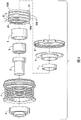
FIG. 1 is a cross-sectional view of the device of the present invention;
FIG. 2 is a cross-sectional view of FIG. 1;
FIG. 3 is a cross-sectional view of FIG. 1;
FIG. 4 is an exploded view of the apparatus of the present invention;
FIG. 5 is a cross-sectional view of an alternative embodiment;
fig. 6 is an exploded view of the alternative embodiment of fig. 5.
Detailed Description
FIG. 1 is a cross-sectional view of the device of the present invention. The alternator isolating decoupler includes a pulley 1, a torsion spring 2, a shaft 3, a bearing 4, a roller one-way clutch 5, a clutch carrier 6, a journal bearing 7, a cover 8 and a spring retainer 9.
Pulley 1 is mounted on shaft 3 via bearings 4 and 7. The one-way clutch 5 is pressed into the clutch carrier 6. The torsion spring 2 connects the clutch carrier 6 to the pulley 1. The torsion spring 2 is connected to the clutch carrier 6 and the spring holder 9 by welding. The spring holder 9 is connected to the pulley 1 by welding. Prior to assembly, the torsion spring 2 can rotate freely in the loading direction with respect to the clutch carrier 6 and the pulley 1.
The use of laser welding to connect the components eliminates the need for welding wires. In laser welding, the metal parent material of each part being welded liquefies and bonds to form a single weld. In an alternative embodiment, a suitable electrode material may be used in the welding process to form the weld to join the components. Exemplary processes include TIG welding or MIG welding.
When a load is applied to the pulley 1 by a belt (not shown), the spring 2 is loaded in the winding direction by its end attached to the spring holder 9. The other end of the torsion spring 2, which is attached to the clutch carrier 6, is loaded against, since the one-way clutch 5 is locked on the shaft 3.
At a predetermined torque, the spring 2 will contract radially to assume a uniform shape whereby each of the spring coils has substantially the same radius. The transition coil 300 contracts to form a continuous helical structure wound on the clutch carrier 6. All coils are normally engaged with the holder 6 and the spring retainer 9. The magnitude of the predetermined torque depends on the application and may be, for example, about 20 Nm.
The transition coil 300 has a radius R2. Each end 21, 22 of the torsion spring has a radius R1. Radius R2 is greater than radius R1. The numerical values provided in the present specification are merely exemplary and are not intended to limit the scope of the present invention.
The spring 2 has a coil at each end 21, 22. Each end coil 21, 22 has a smaller radius than the transition coil 300 in order to be in frictional contact with the clutch carrier 6 and the spring holder 9. Both end coils 21, 22 are ground flat as shown in fig. 1, see surface 100.
Fig. 2 is a cross-sectional view of fig. 1. Surface 100a of end 22 extends between location 400 and location 401. There is a similar flat surface 100b on the end 21. The flat surface 100a provides an annular rim by which the spring end 22 is welded to the bracket 6. The flat surface 100b provides an annular rim by which the end 21 is welded to the holder 9. Each planar surface 100a and 100b is planar in a plane perpendicular to the axis of rotation a-a.
Weld 200 starts at position 400 at the end of the coil and ends at position 401, which position 401 is the starting position for the active coil of spring 2. Weld 200 welds spring 2 to bracket 6. The circumferential length of the weld 200 is less than 360 degrees.
The origin of the active coil is defined by the point where the spring coil is not in contact with any other component of the device, position 401. Position 400 may be located at any position within arc angle β relative to position 401. The position 401 may be located at any position within the arc angle alpha. The coil portion 23 starting at 401 and ending before the transition coil 300 may be used to prevent dynamic loading in multiple directions as the torsion spring 2 is wound and unwound to its rest position during device operation. The inner diameter of the coil part 23 will be in contact with the spring holder 9 or the clutch carrier 6. The welded portion end 22 of the torsion spring 2 is not bent. The length of the protective coil portion 23 determines the dynamic loads to which the welded coil will be subjected during operation. The longer the protective coil portion 23, the less the load of the welded portion of the spring 2 (i.e., the portion of the spring in contact with the weld 200). Thus, the length of the coil portion 23 may be adjusted based on the dynamic needs of a particular application. The weld 200 may be changed to a shorter length, which in turn makes the protective coil longer, thereby reducing the dynamic loads experienced by the weld 200.
By adjusting the angle α and the angle β, and thus the length of the spring protective coil 23, the device can be adjusted to have a specific load on the weld 200. Adjustability allows the user to compensate for manufacturing variations due to component tolerances. This in turn adds more different functionality to the device as it is designed and manufactured for a given system. In some applications, both α and β are equal to zero.
In the following, the table is an example of how the length of the protective coil part 23 may vary. The minimum value of β is 0 °, i.e. the weld 200 starts at the end of the spring. If it is a closed coil spring and the weld 200 extends over the entire circumferential length of the coil, the maximum value of α will be 360 °. The length values of the protective coil 23 in the table are examples for a spring with a coil cross-section of 4.6mm x 4.6 mm. If the cross section is changed, the length of the protective coil 23 will change for a given value of a and β.

The torsional load on the spring end 21 begins at the location 401 of the end of the weld 201. The angle alpha is equal to or greater than zero. The angle beta is equal to or greater than zero. The angle delta is set between the angle alpha and the angle beta. The angle delta is in the range of 90 degrees to 140 degrees. Thus, the total circumference of the weld 200 is: α + β + Δ <360 °.
Fig. 3 is a cross-sectional view of fig. 1. Weld 201 welds the spring retainer 9 to the spring end 21. Weld 201 is located in the portion between ends 403 and 404 bounded by angle γ. Weld 202 is located between spring retainer 9 and pulley 1 between ends 405 and 406.
Although the end 406 may slightly radially overlap the end 404 depending on the radial distance "d" between 404 and 406, the end 406 terminates short of the end 404 by leaving a circumferential gap "a" of about 5 degrees so that the HAZ is not affected. Although there may be a slight radial overlap between the end 405 and the end 403, depending on the radial distance "d" between 403 and 405, the end 405 stops short of the end 403 by leaving a gap "b" of about 5 degrees so that the HAZ is not affected.
Fig. 4 is an exploded view of the device of the present invention. The cap 8 is snap-fitted to the pulley 1. The retainer 6 is press-fitted to the one-way clutch 5.
Fig. 5 is a cross-sectional view of an alternative embodiment. In this alternative embodiment, the spring 2 is welded to the spring retaining ring 21 by a weld 502 and to the pulley 1 by a weld 501. This design allows for a more robust design using two bearings 22, 24. In particular, weld 500 welds spring end 210 to spring support 6. Weld 501 welds end 220 to pulley 1. Weld 502 welds spring retaining ring 21 to end 220. The ring 21 is located radially inside the torsion spring 2.
Unless otherwise stated in this figure, the flat ends of the springs 20 are arranged as described in other figures in this specification.
Fig. 6 is an exploded view of the alternative embodiment of fig. 5.
Although forms of the invention have been described herein, it will be obvious to those skilled in the art that variations may be made in the construction and relation of parts without departing from the spirit and scope of the invention described herein.
Claims (11)
1. An isolating decoupler, comprising:
a shaft;
a pulley journalled to the shaft;
a torsion spring comprising, on each end thereof, a planar surface that is planar in a plane perpendicular to the axis of rotation A-A;
a one-way clutch engaged between the torsion spring and the shaft;
a weld connecting one end of the torsion spring to the one-way clutch; and
a weld connecting the other end of the torsion spring to the pulley.
2. The isolating decoupler of claim 1, wherein the pulley is journaled to the shaft by a bearing.
3. The isolating decoupler of claim 1, further comprising:
a clutch carrier engaged to the one-way clutch; and
the one end portion of the torsion spring is welded to the clutch carrier.
4. The isolating decoupler of claim 1, further comprising:
a spring retainer welded to the pulley; and
the other end of the torsion spring is welded to the spring holder.
5. The isolating decoupler of claim 1, further comprising:
a ring disposed radially inward of the torsion spring;
the other end of the torsion spring is welded to the ring; and is
The torsion spring is welded to the pulley.
6. The isolating decoupler of claim 1, wherein each of the planar surfaces extends circumferentially an angle of less than 360 degrees.
7. The isolating decoupler as in claim 1 wherein a length of the weld connecting the one end of the torsion spring to the one-way clutch comprises portions having angular lengths a, β and Δ and having a total angular length a + β + Δ wherein a is adjacent the active coil of the torsion spring, β is adjacent the one end of the torsion spring and Δ is between a and β.
8. The isolating decoupler as in claim 7, wherein the weld connecting the one end of the torsion spring to the one-way clutch is less than 360 ° in length.
9. The isolating decoupler as in claim 1, wherein the weld connecting the other end of the torsion spring to the pulley is less than 360 ° in length.
10. The isolating decoupler of claim 4, wherein:
the spring retainer is welded to the pulley; and
a heat-affected zone of the weld that welds the spring holder to the pulley does not radially overlap a heat-affected zone of the weld between the other end of the torsion spring and the spring holder.
11. The isolating decoupler as in claim 1, wherein the torsion spring comprises a protective coil portion disposed between a transition coil and an end of the weld connecting the one end of the torsion spring to the one-way clutch.
Applications Claiming Priority (3)
| Application Number | Priority Date | Filing Date | Title |
|---|---|---|---|
| US15/154,713 | 2016-05-13 | ||
| US15/154,713 US9759266B1 (en) | 2016-05-13 | 2016-05-13 | Isolating decoupler |
| PCT/US2017/030437 WO2017196575A1 (en) | 2016-05-13 | 2017-05-01 | Isolating decoupler |
Publications (2)
| Publication Number | Publication Date |
|---|---|
| CN109154327A CN109154327A (en) | 2019-01-04 |
| CN109154327B true CN109154327B (en) | 2021-01-26 |
Family
ID=58699291
Family Applications (1)
| Application Number | Title | Priority Date | Filing Date |
|---|---|---|---|
| CN201780029422.3A Active CN109154327B (en) | 2016-05-13 | 2017-05-01 | Isolation decoupler |
Country Status (10)
| Country | Link |
|---|---|
| US (1) | US9759266B1 (en) |
| EP (1) | EP3455512B1 (en) |
| JP (1) | JP6656418B2 (en) |
| KR (1) | KR102201918B1 (en) |
| CN (1) | CN109154327B (en) |
| AU (1) | AU2017262994B2 (en) |
| BR (1) | BR112018073228B1 (en) |
| CA (1) | CA3023240C (en) |
| MX (1) | MX2018013726A (en) |
| WO (1) | WO2017196575A1 (en) |
Families Citing this family (5)
| Publication number | Priority date | Publication date | Assignee | Title |
|---|---|---|---|---|
| US11028884B2 (en) * | 2018-07-20 | 2021-06-08 | Gates Corporation | Isolating decoupler |
| US11549558B2 (en) * | 2018-08-01 | 2023-01-10 | Gates Corporation | Isolator decoupler |
| CN109854642A (en) * | 2019-03-19 | 2019-06-07 | 上海杰邦塑料五金制品有限公司 | A kind of clutch gear damper |
| US11624434B2 (en) * | 2019-06-14 | 2023-04-11 | Gates Corporation | Isolator |
| US11867275B2 (en) * | 2021-11-30 | 2024-01-09 | Gates Corporation | Belt starter generator tuning device |
Citations (3)
| Publication number | Priority date | Publication date | Assignee | Title |
|---|---|---|---|---|
| CN102498307A (en) * | 2009-09-17 | 2012-06-13 | 盖茨公司 | Isolator decoupler |
| CN104520601A (en) * | 2012-08-07 | 2015-04-15 | 利滕斯汽车合伙公司 | Decoupler carrier with balanced forces |
| US9033832B1 (en) * | 2014-01-23 | 2015-05-19 | Gates Corporation | Isolating decoupler |
Family Cites Families (9)
| Publication number | Priority date | Publication date | Assignee | Title |
|---|---|---|---|---|
| CA2288748C (en) * | 1997-05-07 | 2006-11-28 | Litens Automotive Partnership | Serpentine drive system with improved over-running alternator decoupler |
| JP5026687B2 (en) * | 2004-12-02 | 2012-09-12 | 三ツ星ベルト株式会社 | Pulley structure |
| CN101432541B (en) | 2006-04-26 | 2012-07-04 | 利滕斯汽车合伙公司 | One-way isolator for high torque devices |
| CA2829076A1 (en) * | 2010-06-25 | 2011-12-29 | Litens Automotive Partnership | Isolation pulley with overrunning and vibration damping capabilities |
| US8888622B2 (en) * | 2012-06-04 | 2014-11-18 | The Gates Corporation | Isolator decoupler |
| US9651099B2 (en) * | 2013-01-25 | 2017-05-16 | Litens Automotive Partnership | Clutched device with wrap spring clutch with overrun locking member |
| US8931610B2 (en) | 2013-04-11 | 2015-01-13 | The Gates Corporation | Isolator decoupler |
| JP6352052B2 (en) * | 2014-05-29 | 2018-07-04 | Nskワーナー株式会社 | Ratchet type one-way clutch and claw member setting method |
| US9291253B1 (en) * | 2015-03-24 | 2016-03-22 | Gates Corporation | Isolating decoupler |
-
2016
- 2016-05-13 US US15/154,713 patent/US9759266B1/en active Active
-
2017
- 2017-05-01 WO PCT/US2017/030437 patent/WO2017196575A1/en unknown
- 2017-05-01 KR KR1020187035779A patent/KR102201918B1/en active IP Right Grant
- 2017-05-01 JP JP2018557348A patent/JP6656418B2/en active Active
- 2017-05-01 EP EP17722959.8A patent/EP3455512B1/en active Active
- 2017-05-01 BR BR112018073228-1A patent/BR112018073228B1/en active IP Right Grant
- 2017-05-01 CN CN201780029422.3A patent/CN109154327B/en active Active
- 2017-05-01 MX MX2018013726A patent/MX2018013726A/en unknown
- 2017-05-01 AU AU2017262994A patent/AU2017262994B2/en active Active
- 2017-05-01 CA CA3023240A patent/CA3023240C/en active Active
Patent Citations (3)
| Publication number | Priority date | Publication date | Assignee | Title |
|---|---|---|---|---|
| CN102498307A (en) * | 2009-09-17 | 2012-06-13 | 盖茨公司 | Isolator decoupler |
| CN104520601A (en) * | 2012-08-07 | 2015-04-15 | 利滕斯汽车合伙公司 | Decoupler carrier with balanced forces |
| US9033832B1 (en) * | 2014-01-23 | 2015-05-19 | Gates Corporation | Isolating decoupler |
Also Published As
| Publication number | Publication date |
|---|---|
| WO2017196575A1 (en) | 2017-11-16 |
| CA3023240C (en) | 2020-04-28 |
| AU2017262994A1 (en) | 2018-11-22 |
| US9759266B1 (en) | 2017-09-12 |
| KR20190005970A (en) | 2019-01-16 |
| EP3455512B1 (en) | 2020-04-15 |
| AU2017262994B2 (en) | 2019-06-06 |
| KR102201918B1 (en) | 2021-01-11 |
| BR112018073228B1 (en) | 2023-12-12 |
| MX2018013726A (en) | 2019-03-21 |
| JP6656418B2 (en) | 2020-03-04 |
| CA3023240A1 (en) | 2017-11-16 |
| EP3455512A1 (en) | 2019-03-20 |
| BR112018073228A2 (en) | 2019-02-19 |
| JP2019515217A (en) | 2019-06-06 |
| CN109154327A (en) | 2019-01-04 |
Similar Documents
| Publication | Publication Date | Title |
|---|---|---|
| CN109154327B (en) | Isolation decoupler | |
| CN109154378B (en) | Isolation decoupler | |
| JP7100191B2 (en) | Isolating decoupler | |
| KR102401952B1 (en) | Isolation Decoupler | |
| US11549558B2 (en) | Isolator decoupler | |
| JP2024059988A (en) | Isolating Decoupler |
Legal Events
| Date | Code | Title | Description |
|---|---|---|---|
| PB01 | Publication | ||
| PB01 | Publication | ||
| SE01 | Entry into force of request for substantive examination | ||
| SE01 | Entry into force of request for substantive examination | ||
| GR01 | Patent grant | ||
| GR01 | Patent grant |