CN1091503C - Method and system for controlling combustion - Google Patents
Method and system for controlling combustion Download PDFInfo
- Publication number
- CN1091503C CN1091503C CN 95110449 CN95110449A CN1091503C CN 1091503 C CN1091503 C CN 1091503C CN 95110449 CN95110449 CN 95110449 CN 95110449 A CN95110449 A CN 95110449A CN 1091503 C CN1091503 C CN 1091503C
- Authority
- CN
- China
- Prior art keywords
- signal
- energy
- flame
- fuel
- combustion
- Prior art date
- Legal status (The legal status is an assumption and is not a legal conclusion. Google has not performed a legal analysis and makes no representation as to the accuracy of the status listed.)
- Expired - Fee Related
Links
- 238000002485 combustion reaction Methods 0.000 title claims abstract description 32
- 238000000034 method Methods 0.000 title claims abstract description 20
- 239000000446 fuel Substances 0.000 claims abstract description 28
- 238000001514 detection method Methods 0.000 claims abstract description 16
- 239000003245 coal Substances 0.000 claims abstract description 8
- 238000006243 chemical reaction Methods 0.000 claims description 10
- 230000001276 controlling effect Effects 0.000 claims description 7
- 230000003321 amplification Effects 0.000 claims description 5
- 238000003199 nucleic acid amplification method Methods 0.000 claims description 5
- 230000005855 radiation Effects 0.000 claims description 5
- 230000001105 regulatory effect Effects 0.000 claims description 4
- 239000000523 sample Substances 0.000 abstract description 6
- 238000004939 coking Methods 0.000 abstract 1
- 239000002817 coal dust Substances 0.000 description 10
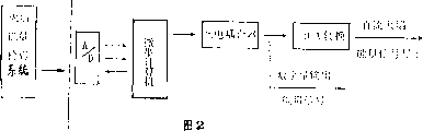
- 238000010586 diagram Methods 0.000 description 3
- 238000002955 isolation Methods 0.000 description 3
- 230000005622 photoelectricity Effects 0.000 description 3
- 230000000295 complement effect Effects 0.000 description 1
- 230000007812 deficiency Effects 0.000 description 1
- 238000005259 measurement Methods 0.000 description 1
- UBCKGWBNUIFUST-YHYXMXQVSA-N tetrachlorvinphos Chemical group COP(=O)(OC)O\C(=C/Cl)C1=CC(Cl)=C(Cl)C=C1Cl UBCKGWBNUIFUST-YHYXMXQVSA-N 0.000 description 1
Images


Landscapes
- Control Of Combustion (AREA)
- Regulation And Control Of Combustion (AREA)
Abstract
Description
Claims (6)

Priority Applications (1)
| Application Number | Priority Date | Filing Date | Title |
|---|---|---|---|
| CN 95110449 CN1091503C (en) | 1995-05-17 | 1995-05-17 | Method and system for controlling combustion |
Applications Claiming Priority (1)
| Application Number | Priority Date | Filing Date | Title |
|---|---|---|---|
| CN 95110449 CN1091503C (en) | 1995-05-17 | 1995-05-17 | Method and system for controlling combustion |
Publications (2)
| Publication Number | Publication Date |
|---|---|
| CN1136155A CN1136155A (en) | 1996-11-20 |
| CN1091503C true CN1091503C (en) | 2002-09-25 |
Family
ID=5077831
Family Applications (1)
| Application Number | Title | Priority Date | Filing Date |
|---|---|---|---|
| CN 95110449 Expired - Fee Related CN1091503C (en) | 1995-05-17 | 1995-05-17 | Method and system for controlling combustion |
Country Status (1)
| Country | Link |
|---|---|
| CN (1) | CN1091503C (en) |
Cited By (1)
| Publication number | Priority date | Publication date | Assignee | Title |
|---|---|---|---|---|
| CN101311629B (en) * | 2007-05-25 | 2010-06-02 | 王泽章 | On-line detection method for controlling station boiler combustion extinguishment |
Families Citing this family (4)
| Publication number | Priority date | Publication date | Assignee | Title |
|---|---|---|---|---|
| CN1093620C (en) * | 1998-07-16 | 2002-10-30 | 中国科学院西安光学精密机械研究所 | On-line detection device for combustion condition of large boiler |
| CN101701719B (en) * | 2009-11-17 | 2011-07-27 | 武汉大学 | Best combustion coal-saving power generation controlling method in thermal power plant and device thereof |
| CN101943397B (en) * | 2010-09-29 | 2012-08-22 | 神华集团有限责任公司 | Control system for pulverized coal boiler system |
| CN102681554B (en) * | 2011-03-10 | 2016-10-12 | 中国恩菲工程技术有限公司 | The control method of oxygen supply in smelting system |
-
1995
- 1995-05-17 CN CN 95110449 patent/CN1091503C/en not_active Expired - Fee Related
Cited By (1)
| Publication number | Priority date | Publication date | Assignee | Title |
|---|---|---|---|---|
| CN101311629B (en) * | 2007-05-25 | 2010-06-02 | 王泽章 | On-line detection method for controlling station boiler combustion extinguishment |
Also Published As
| Publication number | Publication date |
|---|---|
| CN1136155A (en) | 1996-11-20 |
Similar Documents
| Publication | Publication Date | Title |
|---|---|---|
| US4362499A (en) | Combustion control system and method | |
| US5599179A (en) | Real-time combustion controller | |
| GB2141267A (en) | Method of controlling combustion | |
| CN1091503C (en) | Method and system for controlling combustion | |
| JPH01244214A (en) | Method and device for monitoring and controlling air ratio of burner in operation | |
| EP0955499A3 (en) | Process for regulating the firing power in combustion plants | |
| CN102506592A (en) | Portable regulator for automatically testing efficiency of heating furnace | |
| CN109751615A (en) | Control System of Gas-fired Boiler | |
| CA2060882C (en) | Method of operating a refuse incineration plant | |
| US5020451A (en) | Fluidized-bed combustion furnace | |
| GB2065280A (en) | Method of controlling the opacity of the exhaust of the combustion of solid fuel and air in a furnace | |
| EP2385321A2 (en) | A method for regulating the combustion process in solid fuel central heating boilers | |
| US4648242A (en) | Apparatus for providing a constant fuel consumption rate for a fuel powered turbine | |
| CN207702483U (en) | A kind of solid waste desiccation charing combustion control system | |
| DK0561723T3 (en) | Method and apparatus for controlling the amount of air by post-burning in a flue gas collector of a metallurgical reactor | |
| EP2362146B1 (en) | A control method for a pellet and/or biomass combustion apparatus and a pellet and/or biomass combustion apparatus operating according to such a method | |
| CN104818034B (en) | Automatic adjustment method and device for controlling production of nitrogen oxide of coke oven | |
| EP0191353A1 (en) | Control procedure for a boiler plant operating on solid fuel, and corresponding control apparatus | |
| JP3023255B2 (en) | Exhaust gas concentration control device | |
| CN87106029A (en) | Heat release rate control method and equipment | |
| CN109579044A (en) | Air-fuel ratio dynamic feedforward combustion control method for walking beam furnace | |
| JP2762054B2 (en) | Combustion control method for fluidized bed incinerator | |
| JPH0255685B2 (en) | ||
| ATE119649T1 (en) | GAS BURNER WITH COMBUSTION GRID, COMBUSTION METHOD AND HEATING SYSTEM WITH SUCH A BURNER. | |
| JP2947677B2 (en) | Exhaust gas concentration control device |
Legal Events
| Date | Code | Title | Description |
|---|---|---|---|
| C06 | Publication | ||
| PB01 | Publication | ||
| C10 | Entry into substantive examination | ||
| SE01 | Entry into force of request for substantive examination | ||
| C14 | Grant of patent or utility model | ||
| GR01 | Patent grant | ||
| ASS | Succession or assignment of patent right |
Owner name: BEIJING STATE POWER HUAYUAN CONTROL TECHNOLOGY CO Free format text: FORMER OWNER: WANG MANJIA Owner name: NONE Free format text: FORMER OWNER: WANG ZHIYUAN WANG YIDONG Effective date: 20041126 |
|
| C41 | Transfer of patent application or patent right or utility model | ||
| TR01 | Transfer of patent right |
Effective date of registration: 20041126 Address after: 100088, room 416, Cage building, No. 31 middle third ring road, Haidian District, Beijing Patentee after: Beijing Guodian Huayuan Control Technology Co., Ltd. Address before: 100041 Beijing city Shijingshan District Haite garden building 19, unit 1, room 701, Wang man home Co-patentee before: Wang Shiyuan Patentee before: Wang Manjia Co-patentee before: Wang Yidong |
|
| C57 | Notification of unclear or unknown address | ||
| DD01 | Delivery of document by public notice |
Addressee: Liu Guozhen Document name: payment instructions |
|
| C57 | Notification of unclear or unknown address | ||
| DD01 | Delivery of document by public notice |
Addressee: Liu Guozhen Document name: Notification of Termination of Patent Right |
|
| C19 | Lapse of patent right due to non-payment of the annual fee | ||
| CF01 | Termination of patent right due to non-payment of annual fee |