CN109124871B - Laser assisted cataract surgery - Google Patents
Laser assisted cataract surgery Download PDFInfo
- Publication number
- CN109124871B CN109124871B CN201810782796.9A CN201810782796A CN109124871B CN 109124871 B CN109124871 B CN 109124871B CN 201810782796 A CN201810782796 A CN 201810782796A CN 109124871 B CN109124871 B CN 109124871B
- Authority
- CN
- China
- Prior art keywords
- treatment
- laser beam
- pattern
- eye
- closed curve
- Prior art date
- Legal status (The legal status is an assumption and is not a legal conclusion. Google has not performed a legal analysis and makes no representation as to the accuracy of the status listed.)
- Active
Links
Images


Classifications
-
- A—HUMAN NECESSITIES
- A61—MEDICAL OR VETERINARY SCIENCE; HYGIENE
- A61F—FILTERS IMPLANTABLE INTO BLOOD VESSELS; PROSTHESES; DEVICES PROVIDING PATENCY TO, OR PREVENTING COLLAPSING OF, TUBULAR STRUCTURES OF THE BODY, e.g. STENTS; ORTHOPAEDIC, NURSING OR CONTRACEPTIVE DEVICES; FOMENTATION; TREATMENT OR PROTECTION OF EYES OR EARS; BANDAGES, DRESSINGS OR ABSORBENT PADS; FIRST-AID KITS
- A61F9/00—Methods or devices for treatment of the eyes; Devices for putting-in contact lenses; Devices to correct squinting; Apparatus to guide the blind; Protective devices for the eyes, carried on the body or in the hand
- A61F9/007—Methods or devices for eye surgery
- A61F9/008—Methods or devices for eye surgery using laser
- A61F9/00825—Methods or devices for eye surgery using laser for photodisruption
-
- A—HUMAN NECESSITIES
- A61—MEDICAL OR VETERINARY SCIENCE; HYGIENE
- A61F—FILTERS IMPLANTABLE INTO BLOOD VESSELS; PROSTHESES; DEVICES PROVIDING PATENCY TO, OR PREVENTING COLLAPSING OF, TUBULAR STRUCTURES OF THE BODY, e.g. STENTS; ORTHOPAEDIC, NURSING OR CONTRACEPTIVE DEVICES; FOMENTATION; TREATMENT OR PROTECTION OF EYES OR EARS; BANDAGES, DRESSINGS OR ABSORBENT PADS; FIRST-AID KITS
- A61F9/00—Methods or devices for treatment of the eyes; Devices for putting-in contact lenses; Devices to correct squinting; Apparatus to guide the blind; Protective devices for the eyes, carried on the body or in the hand
- A61F9/007—Methods or devices for eye surgery
- A61F9/008—Methods or devices for eye surgery using laser
- A61F9/00821—Methods or devices for eye surgery using laser for coagulation
- A61F9/00823—Laser features or special beam parameters therefor
-
- A—HUMAN NECESSITIES
- A61—MEDICAL OR VETERINARY SCIENCE; HYGIENE
- A61F—FILTERS IMPLANTABLE INTO BLOOD VESSELS; PROSTHESES; DEVICES PROVIDING PATENCY TO, OR PREVENTING COLLAPSING OF, TUBULAR STRUCTURES OF THE BODY, e.g. STENTS; ORTHOPAEDIC, NURSING OR CONTRACEPTIVE DEVICES; FOMENTATION; TREATMENT OR PROTECTION OF EYES OR EARS; BANDAGES, DRESSINGS OR ABSORBENT PADS; FIRST-AID KITS
- A61F9/00—Methods or devices for treatment of the eyes; Devices for putting-in contact lenses; Devices to correct squinting; Apparatus to guide the blind; Protective devices for the eyes, carried on the body or in the hand
- A61F9/007—Methods or devices for eye surgery
- A61F9/008—Methods or devices for eye surgery using laser
- A61F2009/00861—Methods or devices for eye surgery using laser adapted for treatment at a particular location
- A61F2009/0087—Lens
-
- A—HUMAN NECESSITIES
- A61—MEDICAL OR VETERINARY SCIENCE; HYGIENE
- A61F—FILTERS IMPLANTABLE INTO BLOOD VESSELS; PROSTHESES; DEVICES PROVIDING PATENCY TO, OR PREVENTING COLLAPSING OF, TUBULAR STRUCTURES OF THE BODY, e.g. STENTS; ORTHOPAEDIC, NURSING OR CONTRACEPTIVE DEVICES; FOMENTATION; TREATMENT OR PROTECTION OF EYES OR EARS; BANDAGES, DRESSINGS OR ABSORBENT PADS; FIRST-AID KITS
- A61F9/00—Methods or devices for treatment of the eyes; Devices for putting-in contact lenses; Devices to correct squinting; Apparatus to guide the blind; Protective devices for the eyes, carried on the body or in the hand
- A61F9/007—Methods or devices for eye surgery
- A61F9/008—Methods or devices for eye surgery using laser
- A61F2009/00885—Methods or devices for eye surgery using laser for treating a particular disease
- A61F2009/00887—Cataract
- A61F2009/00889—Capsulotomy
-
- A—HUMAN NECESSITIES
- A61—MEDICAL OR VETERINARY SCIENCE; HYGIENE
- A61F—FILTERS IMPLANTABLE INTO BLOOD VESSELS; PROSTHESES; DEVICES PROVIDING PATENCY TO, OR PREVENTING COLLAPSING OF, TUBULAR STRUCTURES OF THE BODY, e.g. STENTS; ORTHOPAEDIC, NURSING OR CONTRACEPTIVE DEVICES; FOMENTATION; TREATMENT OR PROTECTION OF EYES OR EARS; BANDAGES, DRESSINGS OR ABSORBENT PADS; FIRST-AID KITS
- A61F9/00—Methods or devices for treatment of the eyes; Devices for putting-in contact lenses; Devices to correct squinting; Apparatus to guide the blind; Protective devices for the eyes, carried on the body or in the hand
- A61F9/007—Methods or devices for eye surgery
- A61F9/008—Methods or devices for eye surgery using laser
- A61F2009/00897—Scanning mechanisms or algorithms
Abstract
Laser assisted cataract surgery methods and devices utilize one or more treatment laser beams to form a shaped opening in the anterior lens capsule of an eye while performing a capsulorhexis procedure. A light absorbing agent may be applied to the anterior lens capsule to facilitate laser thermal tissue separation along a treatment beam path over the lens capsule. Prior to application of the treatment beam, the relative or absolute reflectance from the eye and optionally from a surgical contact lens can be measured to confirm and optionally quantify the presence of the light absorbing agent.
Description
Divisional application information
The patent application of the invention is a divisional application of an invention patent application with the application date of 2015, 02, 27 and the application number of 201580016670.5 and the name of laser-assisted cataract surgery.
CROSS-REFERENCE TO RELATED APPLICATIONS
This patent application relates to and claims the benefit of priority from the following U.S. patent applications: united states patent application No. 14/193,592 entitled Laser Assisted Cataract Surgery (Laser Assisted Surgery) filed on 28/2/2014; united states patent application No. 14/193,630 entitled Laser Assisted Cataract Surgery (Laser Assisted Surgery) filed on 28/2/2014; united states patent application No. 14/193,671 entitled Laser Assisted Cataract Surgery (Laser Assisted Surgery) filed on 28/2/2014; united states patent application No. 14/193,716 entitled Laser Assisted Cataract Surgery (Laser Assisted Surgery) filed on 28/2/2014; united states provisional patent application No. 61/975,506 entitled Laser Assisted Cataract Surgery (Laser Assisted Surgery) filed on 4/2014; and united states provisional patent application No. 62/047,373 entitled Laser Assisted Cataract Surgery (Laser Assisted Surgery) and filed on 9/8/2014, each of which is incorporated herein by reference in its entirety.
Technical Field
The present invention relates generally to laser assisted ophthalmic surgery and, more particularly, to methods and devices that use one or more lasers in performing capsulorhexis.
Background
Cataracts are a common cause of poor vision and are a major cause of blindness. At least one hundred million eyes have cataracts that result in visual acuity of less than 6/60 (in meters) (or 20/200, in feet). Cataract extraction is the most commonly performed surgical procedure in the world, with an estimated over 2200 million cataract extractions worldwide, and over 3 million cataract extractions performed annually in north america. In general, there are two types of cataract surgery: small incision cataract surgery using phacoemulsification; and extracapsular cataract extraction.
In small incision cataract surgery using phacoemulsification, the more common method is: an approximately 2 millimeter (mm) incision is made in the cornea and the clouded natural lens is removed using irrigation, aspiration, and phacoemulsification, while leaving the elastomeric lens capsule intact to allow implantation and retention of an intraocular lens (IOL). Currently, extracapsular cataract extraction procedures are more invasive procedures and are performed in developing countries with fewer resources. With this procedure, a large incision of 6mm or more is made in the sclera and the entire turbid natural lens is removed.
One of the more critical components of these two surgical procedures is the capsulorhexis, also known as a capsulotomy, which is an incision in the lens capsule made to permit removal of the lens nucleus and cortex. The lens capsule is a transparent homogeneous basement membrane comprising collagen. The lens capsule has elastic properties but is not composed of elastic fibers. The capsule has a smooth surface profile except at the capsule equator where the zonules are attached.
The capsulorhexis typically forms a symmetrical circular incision centered on the visual axis and sized appropriately for the IOL and patient condition. The mechanical integrity around the newly formed incision edge needs to be able to withstand the forces experienced during cataract extraction and IOL implantation. Post-operatively, the newly formed capsular rim hardens and the opening contracts, providing further strength and structural support to the IOL to prevent migration and misalignment.
The current treatment standard for capsulorhexis is Continuous Circular Capsulorhexis (CCC). The concept of CCC is to provide a smooth continuous circular opening through the anterior lens capsule for phacoemulsification and intraocular lens insertion, minimizing the risk of complications including erroneous tears and expansions. Currently, capsulorhexis is performed manually using forceps or a needle. This technique relies on applying shear and minimizing in-plane tension to manually tear the cuts. One complication that can occur when performing a capsulorhexis in this manner is a false tear. A false tear is a radial rupture and propagation of the capsulorhexis towards the equator of the capsule. If a false tear encounters a small band attachment, the tear may be directed to the balloon dome and possibly all the way to the rear of the balloon. Posterior capsular tears promote "drop-in" of the nucleus into the posterior chamber, leading to other complications.
Other problems that can arise in capsulorhexis are related to the surgeon's inability to adequately visualize the capsule due to the lack of red reflectance (red reflectance from the retina), the inability to clamp the capsule with sufficient safety, or the inability to tear a smooth symmetrical circular opening of appropriate size. Additional difficulties may be associated with maintenance of anterior chamber depth after the initial opening, small size of the pupil, or absence of red reflex due to lens clouding. Additional complications arise in elderly patients with weak zonules and in young children with extremely soft and elastic capsules that are extremely difficult to mechanically break.
After cataract surgery, rapidly, 1 to 2 days there is a reaction, in which the capsule becomes hard and capsule shrinkage begins. This contraction continues for the entire 4 to 6 week period, where fibrosis of the capsulorhexis and IOL optic nerve interface and fibrosis of the IOL haptic and capsule interface also occur. The balloon continues to contract to a lesser extent even after more than a year. Therefore, positioning the capsulorhexis is a key factor for long-term success.
Accordingly, there is a need in the art to provide new ophthalmic methods, techniques and devices to improve the processing criteria for capsulorhexis.
Disclosure of Invention
Laser assisted ophthalmic surgical methods and devices are disclosed.
In one aspect, a device for forming an opening in the anterior lens capsule of an eye includes a scanning treatment laser beam having a programmed scanning profile for forming a predetermined treatment pattern of closed curves at the anterior lens capsule. The treatment laser has a wavelength selected to be strongly absorbed at the anterior lens capsule and a power selected to cause thermal denaturation of collagen in the anterior lens capsule producing thermal tissue separation along the closed curve without ablating anterior lens capsule tissue. The device also includes a scanning visualization laser beam having a programmed scanning profile for a predetermined visualization pattern at the anterior lens capsule and a wavelength in the visible spectrum.
The visualization pattern is different in size and geometry from the treatment pattern. For example, at least a portion of the visualization pattern may indicate desired boundaries of the opening to be formed in the anterior lens capsule and thereby facilitate alignment of the treatment pattern on the anterior lens capsule. Typically, the location of the desired boundary of the opening is different than the closed curve of the treatment pattern due to contraction of anterior lens capsule tissue adjacent to the closed curve during and after thermal tissue separation. Alternatively or additionally, at least a portion of the visualization pattern may correspond to one or more anatomical features of the eye, and thereby facilitate alignment of the treatment pattern relative to those anatomical features.
In another aspect, an apparatus for forming an opening in the anterior lens capsule of an eye includes a treatment laser beam and a two-dimensional scanner on which the treatment laser beam is incident. The scanner has a programmed scan profile for a predetermined treatment pattern in which the treatment laser beam is scanned to form a closed curve at the anterior lens capsule. The device includes a lens positioned to focus the treatment laser beam at the anterior lens capsule to a beam waist, wherein the treatment beam expands from its beam waist to defocus on the retina of the eye. The treatment pattern passes a treatment pattern invariant and/or a treatment pattern beam waist between the lens and the eye. The treatment laser beam has a wavelength selected to be strongly absorbed at the anterior lens capsule and a power selected to cause thermal denaturation of collagen in the anterior lens capsule producing thermal tissue separation along the closed curve of the treatment pattern without ablating anterior lens capsule tissue.
The treatment pattern may diverge in the eye, and thus the size and area of the treatment pattern on the retina may be expanded compared to the size and area of the treatment pattern at the anterior lens capsule. Thus, the treatment pattern may avoid the fovea on the retina.
In another aspect, a device for forming an opening in the anterior lens capsule of an eye includes a continuous wave scanning treatment laser beam having a programmed scanning profile for forming a predetermined treatment pattern of a closed curve in a single pass at the anterior lens capsule. The treatment laser has a wavelength selected to be strongly absorbed at the anterior lens capsule and a power selected to cause thermal denaturation of collagen in the anterior lens capsule producing thermal tissue separation along the closed curve without ablating anterior lens capsule tissue. At the beginning of the treatment pattern, the power of the treatment laser is ramped up from about 0 to about 90% of its full power during a period of about 5 milliseconds to about 200 milliseconds. This ramp up can minimize the likelihood of the balloon tearing at the beginning of the treatment pattern by: allowing tissue near the starting point of the pattern to first tighten without separating, thereby reducing shear/tension at the start of the pattern; and/or avoid or minimize local shock waves in the fluid adjacent to the target tissue that may otherwise result from the growth and destruction of one or more vapor bubbles with faster thermal turn-on.
In another aspect, an apparatus for forming an opening in the anterior lens capsule of an eye includes a treatment laser beam and a two-dimensional scanner on which the treatment laser beam is incident. The scanner has a programmed scan profile for a predetermined treatment pattern in which the treatment laser beam is scanned to form a closed curve at the anterior lens capsule. The device includes a lens positioned to focus the treatment laser beam at the anterior lens capsule to a beam waist, wherein the treatment laser beam expands from its beam waist to defocus on a retina of the eye. The treatment laser beam has a wavelength selected to be strongly absorbed at the anterior lens capsule and a power selected to cause thermal denaturation of collagen in the anterior lens capsule producing thermal tissue separation along the closed curve of the treatment pattern without ablating anterior lens capsule tissue. The device further comprises: a first visible light visualization laser beam sharing an optical path with the treatment laser beam; and a second visible light visualization laser beam intersecting the first visualization laser beam at or about the beam waist of the treatment laser beam.
For example, the first and second visualization laser beams may be generated from a single visible laser beam incident on the scanner by dithering the scanner between the optical path of the first visualization laser beam and the optical path of the second visualization laser beam.
In another aspect, a virtual visualization pattern may be presented on the display and overlaid with a view of the anterior lens capsule to assist in the ophthalmic surgical procedure described herein. Such virtual visualization patterns may also be used instead of or in addition to the projected visualization patterns described herein.
In another aspect, the visual axis of a patient's eye may be determined by gazing (looking directly at) a patient at a low power laser beam prior to or during an ophthalmic surgical procedure. Optionally, the laser beam may flash at a patient-perceptible frequency to facilitate fixation of the beam.
In another aspect, the orientation of a toric IOL implanted in a patient's eye can be assessed by having the patient fixate on a low-power laser beam and observing the reflection of the laser beam from the back of the patient's eye through the toric IOL.
In another aspect, the relative or absolute reflectance from the eye can be measured to identify and optionally quantify light absorbing agents present in or on the anterior lens capsule. Such measurements may be used to determine: there is sufficient light absorber in the lens capsule such that the transmission of the treatment beam through the capsule will be below a predetermined threshold that is considered safe for the retina and other internal portions of the eye. Such measurements may also be used to determine: there is sufficient light absorber to produce complete laser thermal separation of the anterior capsule along the treatment beam path upon application of the selected/preprogrammed treatment beam parameters. These determinations may utilize a correlation between the transmittance of the treatment beam through the balloon at a treatment wavelength or another wavelength and the reflectance from the balloon. Additionally or alternatively, the reflectance measurements and their correlation to the transmittance of the treatment beam through the lens capsule can be used to optimize treatment parameters, such as treatment beam power, spot diameter, and scan speed.
These and other embodiments, features and advantages of the present invention will become more apparent to those skilled in the art upon reference to the following more detailed description of the invention, taken in conjunction with the accompanying drawings, which are first briefly described.
Drawings
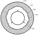
Fig. 1 shows a transverse plane view of certain portions of the eye (lens capsule 110, dilated iris 140, cornea 160, anterior chamber 170, and pupil 190), the natural crystalline lens location and intended location of the implanted intraocular lens 120, light absorbers 130, and a treatment beam 150 to be used in examples of the capsulorhexis procedure described herein.
Fig. 2 shows a side view of the lens capsule 110 of fig. 1, where the lens capsule 110 has been separated into two portions, such as an outer portion 110-E and an inner portion 110-I, at location 210 by a laser-based method as described herein. This figure also shows the constricted and constricted ends 220-E and 220-I that define the boundary for the separation.
Fig. 3A-3H show views from the front of the lens capsule illustrating an exemplary "inside-closed curve-inside" treatment pattern, wherein the treatment laser beam is directed along a predetermined closed curve 310.
Fig. 4A-4G show views from the front of the lens capsule illustrating an exemplary "inside-closed curve" treatment pattern, with the treatment laser beam directed along a predetermined closed curve 410.
Fig. 5A-5H show views from the front of the lens capsule illustrating an exemplary "inside-closed curve-overlap" treatment pattern, wherein the treatment laser beam is directed along a predetermined closed curve 410.
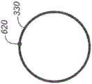
Fig. 6A-6G show views from the front of the lens capsule illustrating an exemplary "closed curve-overlap" treatment pattern, with the treatment laser beam directed along a predetermined closed curve 610.
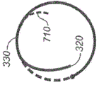
Fig. 7A-7H show views from the front of the lens capsule illustrating an exemplary "inside-closed curve-overlap-inside" treatment pattern, wherein the treatment laser beam is directed along a predetermined closed curve 710.
Fig. 8 shows a view of an eye having a rim 810, an iris 140, an inner boundary 820 of the iris, a pupil 190, and a visualization pattern comprising a predetermined closed curve and at least three points 830 for assisting in locating the location of a desired capsulorhexis.
Fig. 9A-9B show views of an eye including a rim 810, an iris 140, and a pupil 190 with two additional example visualization patterns superimposed thereon, each of which includes two circles or closed curves 910 and 920.
Fig. 10A-10B show views of an eye including a rim 810, an iris 140, and a pupil 190 with two additional example visualization patterns superimposed thereon, each of which includes two circles or closed curves 1010 and 1020 with a point 1030 on the curve.
Fig. 11A-11B show views of an eye including a rim 810, an iris 140, and a pupil 190 with two additional example visualization patterns superimposed thereon, each of which includes a cross-hair and two circles or closed curves with points on the curves.
Fig. 12A-12L show additional visualization patterns, each of which may include a combination of a closed curve 1205, 1210, 1220, 1260, a point 1230 on the curve, and a cross-hair 1240.
Fig. 13A-13B show examples of elliptical fractures having major and minor axes and angles of rotation. Fig. 13C-13D show two examples of visualization patterns that may be used with the elliptical fractures of fig. 13A-13B. Each pattern includes a circular outer closed curve and an elliptical inner closed curve.
Fig. 14 shows a view of an eye having: the rim 810, the iris 140, the inner boundary 820 of the iris, the dilated pupil 190, the visualization pattern comprising the cross-hair 1440 and two circles 1460 (with points 1430 on the curve), and the treatment beam pattern for the circular break 1490.
Fig. 15 shows a view of an eye having: the rim 810, the iris 140, the inner boundary 820 of the iris, and the visualization pattern of the dilated pupil 190, the outer circle 1520 including the cross-hair 1540 and having a point 1530, and the inner ellipse 1510 having a point 1530, and the treatment beam pattern for the elliptical break 1590.
Fig. 16 shows a plot of power versus time for an example treatment laser output pulse delivered to collagen containing tissue usable in the devices and methods described herein.
FIG. 17 illustrates the dependence of power as a function of irradiated area required to achieve thermal separation of the anterior capsule in the eye. Power has a low dependence at smaller areas, and as the area increases, there is a greater dependence of power on the irradiated area.
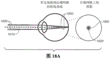
Fig. 18A-18C show three exemplary ray traces of a scanning laser beam directed into the eye through the cornea and crystalline lens and onto the retina, and the resulting projections of the scanning laser beam on the retina. Fig. 18A shows a ray trace without the presence of a surgical contact lens, and fig. 18B-18C show ray traces with the presence of two different surgical contact lenses.
Fig. 19 shows elements of an example device that may be used to scan a laser beam in an eye to perform ophthalmic surgery as described herein.
Fig. 20 shows the example device of fig. 19 externally integrated with a microscope as an attachment to the microscope.
Fig. 21 shows the example device of fig. 19 internally integrated with a microscope with a shared illumination mirror and microscope objective.
Fig. 22 shows another example device similar to the example device of fig. 19 but also including optical elements that facilitate depth alignment relative to the tissue to be treated.
Fig. 23A-23C show views of two superimposed visualization patterns produced by the device of fig. 22 when adjusting the depth alignment of the device.
24A-24B show two example foot-operable controls that may be used to control the device of FIG. 22.
Fig. 25 shows an example device similar to the device of fig. 19-22 that can be used to scan a laser beam in an eye to perform ophthalmic surgery, where the device integrated externally with the microscope has a display on which a virtual visualization pattern can overlay a through microscope view of the surgical field.
Fig. 26A shows an oscilloscope trace for a measurement of the time-dependent transmission of a treatment laser beam through the anterior lens capsule treated with a light absorbing agent.
Fig. 26B shows the data presented in the transmittance versus time plot of fig. 26A.
Fig. 27A and 27B show example images and graphs of relative reflectance, respectively, illustrating a decrease in reflectance of broadband illumination from the lens capsule with increasing amount of light absorber applied to the capsule.
Fig. 28A and 28B show, respectively, example images and graphs of relative reflectance illustrating the decrease in reflectance of narrow band (red) visualization laser illumination from the lens capsule with increasing amount of light absorber applied to the capsule.
FIG. 29 shows a graph of transmittance through the anterior lens capsule treated with increasing amounts of light absorbing agent at a treatment beam wavelength and reflectance through the anterior lens capsule treated with increasing amounts of light absorbing agent at another wavelength.
FIG. 30 shows a graph illustrating the correlation between the transmittance and reflectance curves shown in FIG. 29.
Detailed Description
The following detailed description should be read with reference to the drawings, in which like reference numerals refer to like elements in the various drawings. The drawings, which are not necessarily to scale, depict alternative embodiments and are not intended to limit the scope of the disclosure. The detailed description illustrates by way of example, not by way of limitation, the principles of the invention. This description will clearly enable one skilled in the art to make and use the invention, and describes several embodiments, adaptations, variations, alternatives and uses of the invention, including what is presently believed to be the best mode of carrying out the invention. As used in this specification and the appended claims, the singular forms "a", "an", and "the" include plural referents unless the context clearly dictates otherwise.
As described in greater detail below, the present specification discloses ophthalmic surgical methods and devices that utilize one or more treatment laser beams to form a shaped opening in the anterior lens capsule of an eye when performing a capsulorhexis procedure. In the process, a light absorber can optionally be added on or into the lens capsule tissue, and the treatment laser wavelength is selected to be very strongly absorbed by the light absorber. Alternatively, the treatment laser wavelength may be selected to be absorbed by the tissue itself or strongly, in which case no additional light absorber need be used. In either case, the phrase "very strongly absorbed" as used herein is intended to mean that the transmission of the treatment beam through the tissue to be treated (e.g., the anterior lens capsule) is less than about 65%, or less than about 40%, or less than about 30%, or less than about 20%, or less than about 15%, or less than about 10%. For example, in some variations, the treatment beam is very strongly absorbed, such that the transmission through the tissue to be treated is about 11% +/-3%. A therapeutic laser beam is directed at the lens capsule tissue along a predetermined closed curve to produce a thermal effect in the tissue to produce separation of the tissue along the laser beam path. For example, the predetermined closed curve may have a circular or elliptical shape. Any other suitable shape for the closed curve may also be used. Typically, the shape is selected to reduce the likelihood of a tear occurring on the edge of the separated edge of tissue formed outside of the closed curve during cataract surgery. Visualization patterns generated using one or more target laser beams may be projected onto the lens capsule tissue to assist in the process.
The general aspects of these methods and apparatus may be better understood with reference to fig. 1 and 2. Fig. 1 shows the intended location of intraocular lens 120 to be implanted after the capsulorhexis procedure in a transverse plan view of the eye, including lens capsule 110, dilated iris 140, cornea 160, anterior chamber 170, and pupil 190. In the illustrated example, the light absorber 130 is added into or onto a layer of the anterior lens capsule 110. This agent may be a biocompatible agent such as Indocyanine green (Indocyanine green) or Trypan Blue (Trypan Blue), a dye, a pigment, a nanoparticle, a carbon particle, or any other suitable light absorbing agent. For example, the light absorbing agent may be trypan blue, other Vital dyes (Vital Dye), or indocyanine green. A light beam 150 (e.g., a laser beam) may then be directed along a closed curve path over the anterior lens capsule. The guided light beam is absorbed by the light absorber to store thermal energy in or produce a local thermal effect on the anterior lens capsule to create a capsulorhexis.
Referring now to fig. 2, in general, the wavelength, power, speed of beam movement along the closed curve, and spot size on the treated tissue are selected such that the beam can be absorbed by the light absorber to be adjacent to or store sufficient thermal energy at the anterior lens capsule to create a mechanical separation 210 in the anterior lens capsule. The laser beam parameters are typically selected to avoid ablation of the tissue, and instead, the mechanical separation is believed to result from thermal denaturation of collagen in the tissue (for example, where collagen transitions from a crystalline helical structure to an amorphous structure). The denatured collagen contracts and contracts to form thickened rims 220-E and 220-I that define boundaries for separation forming a capsulorhexis. Advantageously, these rims may be more elastic and resistant to tearing than the original film.
For clarity and convenience, various features and aspects of the inventive methods and apparatus are described below under separately identified headings. This organization of the description is not meant to be limiting. Variations of the methods and devices described herein may include or employ any suitable combination of the aspects or features described under the separate headings.
Therapeutic light beam pattern
Fig. 3A-3H illustrate an exemplary "inside-closed curve-inside" treatment pattern in which a treatment laser beam is directed along a predetermined closed curve 310. The treatment pattern begins inside the closed curve, progresses around the closed curve, and then terminates inside the closed curve. Although illustrated as clockwise, this pattern may also be counterclockwise. The dashed line 310 of fig. 3A represents the complete pattern. The point 320 in fig. 3B indicates the starting point of the pattern inside the closed curve, and the delivery of fig. 3C-3H through the pattern illustrates the progression of the pattern at a subsequent time interval with a solid line 330. Point 340 in fig. 3H indicates the end point of the treatment pattern inside the closed curve. The positioning process at the beginning and end points inside the closed curve (to remove material from the eye) helps prevent irregularities in the shape of the curve that can contribute to tearing of the rim of the retained anterior lens capsule that is outside the closed curve.
Fig. 4A-4G illustrate exemplary "inside-closed curve" treatment patterns, in which a treatment laser beam is directed along a predetermined closed curve 410. The treatment pattern begins inside the closed curve, progresses around the closed curve, and then terminates on the closed curve. Although illustrated as clockwise, this pattern may also be counterclockwise. The dashed line 310 of fig. 4A represents the complete pattern. The point 320 in fig. 4B indicates the starting point of the pattern inside the closed curve, and the delivery of fig. 4C-4G through the pattern illustrates the progression of the pattern at a subsequent time interval with a solid line 330. Point 440 in fig. 4G indicates the end point of the treatment pattern on the closed curve.
Fig. 5A-5H illustrate exemplary "inside-closed curve-overlap" treatment patterns, wherein the treatment laser beam is directed along a predetermined closed curve 410. The treatment pattern begins in the inner region of the closed curve, progresses around the closed curve (with an overlapping region on the closed curve), and then terminates on the closed curve. Although illustrated as clockwise, this pattern may also be counterclockwise. The dashed line 410 of fig. 5A represents the complete pattern. The point 320 in fig. 5B indicates the starting point of the pattern inside the closed curve, and the delivery of fig. 5C-5H through the pattern illustrates the progression of the pattern at a subsequent time interval with a solid line 330. Point 540 in fig. 5H indicates the end point of the treatment pattern on the closed curve, where region 550 on the closed curve undergoes treatment exposure of the laser light at the very beginning of the pattern and is again delivered towards a later part of the pattern, i.e. region 550 is an overlapping region.
Fig. 6A-6G illustrate exemplary "closed curve-overlap" treatment patterns, in which a treatment laser beam is directed along a predetermined closed curve 610. The treatment pattern begins on the upper closed curve, progresses around the closed curve with overlapping regions on the closed curve, and then terminates on the closed curve. Although illustrated as counterclockwise, such a pattern may also be clockwise. The dashed line 610 of fig. 6A represents the complete pattern. Point 620 in fig. 6B indicates a starting point on the closed curve, and the delivery of fig. 6C-6G through the pattern illustrates the progression of the pattern at a subsequent time interval with solid line 330. Point 540 in fig. 6G indicates the end point of the treatment pattern on the closed curve, where region 550 on the closed curve undergoes treatment exposure of the laser light at the very beginning of the pattern and is again delivered towards a later part of the pattern, i.e. region 550 is an overlapping region.
Fig. 7A-7H illustrate exemplary "inside-closed curve-overlap-inside" treatment patterns, wherein a treatment laser beam is directed along a predetermined closed curve 710. The treatment pattern begins inside the closed curve, then progresses around the closed curve (with an overlapping region on the closed curve), and then terminates inside the closed curve. Although illustrated as clockwise, this pattern may also be counterclockwise. The dashed line 710 of fig. 7A represents the complete pattern. The point 320 in fig. 7B indicates a starting point inside the closed curve, and the delivery of fig. 7C-7H through the pattern illustrates the progression of the pattern at a subsequent time interval with a solid line 330. As shown in fig. 7G-7H, the area 550 on the closed curve undergoes therapeutic exposure of the laser light at the very beginning of the pattern and is again delivered towards a later part of the pattern, i.e. the area 550 is an overlapping area. Point 340 in fig. 7H indicates the end point of the treatment pattern inside the closed curve.
Any other suitable treatment beam pattern may also be used. For example, a manufacturer may pre-program one or more treatment beam pattern shapes into a laser capsulorhexis device (described in more detail below). At or prior to treatment, the operator may then select the size (e.g., diameter) and shape of the closed curve defining the treatment pattern or select the size (e.g., diameter) and shape of the desired break to be created by the closed curve of the treatment pattern, for example.
Visualization/targeting patterns
As described above, the visualization pattern generated using one or more laser beams (typically of a different wavelength than the treatment beam) may be projected onto the lens capsule tissue to assist in the treatment process. The shape and diameter of the visualization pattern may be different from the shape and diameter of the treatment beam pattern. Although the visualization pattern or portions of the visualization pattern may overlay the closed curve of the treatment pattern to indicate at least a portion of the path that the treatment beam will take, this is not required. Alternatively or additionally, at least a portion of the visualization pattern may overlay the intended location of the outer rim of the opening that would result from the tissue separating the treatment beam or otherwise indicate the desired outcome of the treatment. The location of the outer rim is typically different from and has a larger diameter than the closed curve of the treatment beam pattern for two reasons: (i) the lens capsule tissue is under tension while in the eye (much like a drum head), so that when the tissue along a closed curve is separated, the outer portion is under tension and pulled to the periphery, thereby enlarging the diameter; (ii) the mechanism of action for the therapeutic laser will locally heat the irradiated anterior capsule on the closed curve, which heating tends to cause the collagen tissue to contract, contract and separate externally and internally away from the heated closed curve. Alternatively or additionally, at least a portion of the visualization pattern may correspond to one or more particular anatomical features of the eye. This may cause the visualization pattern (and thus the treatment beam pattern) to be centered on the anatomy of the eye or otherwise cause the visualization and treatment beams to be aimed. The visualization pattern may optionally comprise a cross hair.
Fig. 8 illustrates an example visualization pattern 830 that includes a closed curve and at least three points that can be used to assist in locating a desired location of a capsulorhexis. The map also identifies the limbus 810 of the eye to be treated, the iris 140, the inner boundary 820 of the iris, and the pupil 190.
Fig. 9A-9B each show a view of an eye including a rim 810, an iris 140, and a pupil 190, onto which an example visualization pattern 900 comprising two concentric circles or closed curves 910 and 920 is projected. The inner circle or closed curve 910 represents the size and location of the desired opening in the anterior capsulorhexis. An outer circle 920 (which may be sized independently of the inner circle size) may be used to center the capsulorhexis on the rim, as illustrated in fig. 9A. Alternatively, the outer circle may be sized to allow centering on the inner boundary of the dilated pupil, as represented in fig. 9B.
Fig. 10A-10B each show a view of an eye including a rim 810, an iris 140, and a pupil 190, onto which an example visualization pattern 1000 comprising two concentric circles or closed curves 1010 and 1020 (with a point 1030 on the curve) is projected. The combination of lines and/or curves and points provides a pattern that is easily focused on the target tissue. The lines are created by moving the visualization beam along the desired pattern. The spots are generated by having the visualization beam stay at the spot locations in the scan pattern for a longer period. The points may provide enhanced visualization on the target tissue because the points are denser than the lines. The inner circle or closed curve 1010 represents the size and location of the desired opening in the anterior capsulorhexis. An outer circle 1020 (which may be sized independently of the inner circle size) may be used to center the capsulorhexis on the rim, as illustrated in fig. 10A. Alternatively, the outer circle may be sized to cause centering on the inner boundary of the dilated pupil, as represented in fig. 10B.
Fig. 11A-11B each show a view of an eye including a rim 810, an iris 140, and a pupil 190, an example visualization pattern 1100 comprising two concentric circles or closed curves 1110 and 1120 (with points 1130 on the curves) and a cross-hair 1140 being projected onto the eye. The combination of lines and dots provides a pattern that is easily focused on the target tissue. The lines are created by moving the visualization beam along the desired pattern. The spots are generated by having the visualization beam stay at the spot locations in the scan pattern for a longer period. The points may provide enhanced visualization on the target tissue because the points are denser than the lines. The inner circle or closed curve 1110 represents the size and location of the desired opening in the anterior capsulorhexis. An outer circle 1120 (which may be sized independently of the inner circle size) may be used to center the capsulorhexis on the rim, as illustrated in fig. 11A. Alternatively, the outer circle may be sized to cause centering on the inner boundary of the dilated pupil, as represented in fig. 11B. The addition of the cross-hairs further enhances the ability to focus and center the visualization pattern.
Fig. 12A-12L show additional visualization patterns, each of which may include a combination of inner closed curves 1205, 1210 and outer closed curves 1220, points 1230 on the curves, points 1230 not on the curves, a cross-hair 1240, a dashed arc 1250, and/or straight line segments 1260 forming closed curves. In general, the closed visualization curves shown in these and other figures may be formed from straight line segments that may be easier to program and/or easier to generate than curve arcs.
Fig. 13A-13B show an example of an elliptical fracture 1300 having major and minor axes and an angle of rotation. Fig. 13C-13D show two examples of visualization patterns that may be used with the elliptical fractures of fig. 13A-13B. Each pattern includes a circular outer closed curve and an elliptical inner closed curve (1320 and 1310, respectively, in fig. 13C), a point 1330 on the curve, and a cross 1340. In fig. 13D, a closed curve is formed with straight line segment 1360. The oval inner closed curve represents the size and location of the desired opening in the anterior capsulorhexis. For example, an outer circle (which may be sized independently of the inner ellipse size) may be used to center the capsulorhexis on the rim.
Fig. 14 shows a view of an eye including an edge 810, an iris 140, an inner boundary 820 of the iris, and a pupil 190, onto which an example visualization pattern 1400 comprising two concentric closed circles or curves (with points 1430 on the curves) and a cross hair 1440 is projected. The closed curve is formed by a straight line segment 1460. The inner circle or closed curve represents the size and location of the desired opening in the anterior capsulorhexis. An outer circle (which may be sized independently of the inner circle) may be used to center the capsulorhexis on the rim, as illustrated. Alternatively, the outer circle may be sized to facilitate centering on the inner boundary of the dilated pupil. This figure also shows a treatment beam pattern 1490 for the desired circular fracture. The treatment beam pattern 1490 is different from and has a smaller diameter than the closed circle in the visualization pattern.
Fig. 15 shows a view of an eye including an edge 810, an iris 140, an inner boundary 820 of the iris, and a pupil 190, an example visualization pattern 1500 comprising an outer circular closed curve 1520 and an inner elliptical closed curve 1510, points 1530 on the curves, and a cross-hair 1540 being projected onto the eye. The oval inner closed curve represents the size and location of the desired opening in the anterior capsule. An outer circle (which may be sized independently of the inner ellipse) may be used to center the capsulorhexis on the rim, as illustrated. Alternatively, the outer circle may be sized to facilitate centering on the inner boundary of the dilated pupil. This figure also shows a treatment beam pattern 1590 for a desired elliptical break. The treatment beam pattern 1590 is different from and smaller than the ellipse within the visualization pattern.
Any other suitable visualization beam pattern may also be used. For example, a manufacturer may pre-program one or more visualization beam pattern shapes into a laser capsulorhexis device (described in more detail below). At or before the time of treatment, the operator may then select the pattern size and shape to be used to guide the treatment, for example.
The position of the visual axis relative to the rim or center on the dilated pupil may also be measured on a separate diagnostic device. Offset data from center may then also be manually or automatically entered into the laser capsulorhexis device. In such cases, the visualization pattern may be arranged such that when an outer portion of the visualization pattern (e.g., a circle) is positioned or centered on the eye anatomy of the limbus or dilated pupil, the center of an inner portion of the visualization pattern (e.g., a circle or ellipse) is offset from the center of the limbus or dilated pupil to be on the visual axis. The center of the closed curve of the treatment pattern may be correspondingly offset from the edge or center of the dilated pupil, such that the center circle or ellipse of the visualization pattern indicates the perimeter to be disrupted.
The visualization pattern laser beam may have any suitable wavelength in the visible spectrum. The visualization beam may be scanned across the tissue to be treated at a speed of, for example, greater than about 450 mm/sec, but the visualization beam may also dwell to form dots or other lighter features in the visualization pattern. Any suitable scanning speed may be used. For example, the diameter of the visualization beam on the tissue surface may be about 50 microns to about 600 microns. The visualization laser beam power at the tissue may be, for example, less than about 10mW or less than about 1mW when the beam rests on a point in the visualization pattern. The power of the visualization beam, as it scans, may be, for example, less than about 30 mW. In general, the power and wavelength of the laser beam are selected to provide a sufficiently visible visualization pattern without significantly depleting any absorbent that has been deposited on the tissue to facilitate treatment.
Treatment beam and scan parameters
In general, the parameters characterizing the treatment laser beam and the treatment beam scanning process are selected to provide the desired laser-induced thermal tissue separation at the treated tissue while minimizing or reducing the risk of damage to the retina. For example, these laser and scanning parameters may include laser wavelength, laser beam power, spot size at the treated tissue, fluence and peak irradiance at the treated tissue, spot size on the retina, fluence and peak irradiance on the retina, scanning speed, time profile of the laser beam during scanning, and scan pattern size and position on the retina.
Typically, the treatment beam from the continuous wave laser traces the treatment beam pattern in a single pass over a time period of, for example, less than about 10 seconds, less than about 5 seconds, less than about 1 second, about 10 seconds, about 5 seconds, or about 1 second. The treatment beam may be moved across the treated tissue at a speed of, for example, about 20 millimeters per second (mm/s) for a 1 second scan to about 2mm/s for a 10 second scan, although any suitable scanning speed and duration may be used. Since movement of the continuous wave laser beam along the treatment path occurs during irradiation of the treated tissue (for example, rather than between discrete laser pulses), and thus all portions of the rim are formed with the same or similar irradiation and thermal conditions, the formation of irregularities or tears in the resulting rim of the tissue is reduced or avoided. Using a single pass of the treatment beam also helps ensure completion of the capsulorhexis even if there is slight movement of the eye relative to the trajectory.
In variations where the treatment beam path begins inside the closed curve of the treatment pattern (see, for example, fig. 4C), the initial scan speed in the inner portion of the treatment path may be less than the scan speed along the closed curve. For example, the scan speed on the inner portion may be ramped up to the speed used along the closed curve. For example, the average speed along the inner portion may be about 1/2 for the scan speed used along the closed curve, or about 2/3 for the scan speed used along the closed curve, or between about 1/2 and about 2/3 for the scan speed used along the closed curve.
Referring now to the plot of laser power versus time shown in fig. 16 for an example treatment beam scan, at the beginning of the treatment scan, the power in the treatment beam may be ramped up slowly (and optionally monotonically, as shown, time-efficient). As described above in the summary section, this slow ramp up may allow tissue near the beginning of the pattern to first tighten without separating, thereby reducing the shear/tension at the beginning of the pattern. This slow ramp may also avoid or minimize local shock waves in the fluid adjacent to the target tissue that may otherwise result from faster thermal communication. For example, the laser beam may monotonically ramp from 0 to about 90% of full treatment power over a period from about 5 milliseconds (ms) to about 200ms (e.g., about 100 ms). This power ramp-up typically occurs as the laser beam is scanned along the initial portion of the treatment path. In variations where the treatment beam path begins inside the closed curve of the treatment pattern (see again, for example, fig. 4C), the ramping up of the laser beam power may occur along an initial inner portion of the treatment path and be completed before the laser beam reaches the closed curve portion of the treatment pattern. In such variations, the scanning speed of the beam along the initial inner portion of the treatment path may also be ramped up to the speed used along the closed curve, as described above. For example, the average speed along the inner portion of the path may be about 25% of the scan speed used along the closed curve.
As shown in fig. 16, the off of the treatment laser beam pulses at the end of the treatment scan may be much more abrupt than on.
As described earlier in this specification, the treatment laser beam wavelength can be selected to be strongly absorbed by a light absorber that is optionally added onto or into the tissue to be treated. For example, the treatment laser may operate at a wavelength of about 577 nanometers, or about 590 nanometers, or about 810 nanometers. In such examples, the light absorber (if used) can be trypan blue or indocyanine green, respectively. Alternatively, the treatment laser wavelength may be selected to be absorbed by the tissue itself or strongly absorbed. Any suitable wavelength for the therapeutic light beam may be used.
As described in more detail below, typically, the treatment laser beam is focused to a beam waist at or near the location of the tissue to be treated, and then the diameter of the treatment laser beam expands as it propagates to the retina. Furthermore, in general, the scan pattern is expanded on the retina compared to the size of the scan pattern on the tissue being treated. Thus, the parameters (e.g., fluence and peak irradiation for the treatment beam) may have different and larger values at the treated tissue than the parameter values at the retina.
The methods and devices disclosed herein generally rely on laser-induced thermal tissue separation rather than on laser-induced ablation, and thus can use much lower treatment beam fluence and peak irradiance values at the treated tissue than are typically required for other laser-based surgical procedures. Additionally, the methods and devices disclosed herein may use a therapeutic laser beam having a relatively high average power but that does not produce peak irradiance values that may damage the retina or other eye tissue, as these methods and devices may use long (e.g., 1-10 second) pulses from continuous wave lasers. In contrast, laser-based surgical procedures using much shorter Q-switched or mode-locked laser pulses may need to operate at much lower average powers to avoid peak irradiance values that may cause damage, which may increase the time required to provide a desired fluence.
For example, the average power of the treatment beam can be about 300mW to about 3000mW, which is selected depending in part on the absorption intensity of the absorber at the treatment beam wavelength or the absorption intensity of the treated tissue at the treatment beam wavelength. Any suitable average power may be used.
The fluence of the treatment beam on a particular tissue depends on the average power of the treatment beam, the diameter of the treatment beam at the tissue, and the scanning speed of the treatment beam across the tissue. For the methods and devices disclosed herein, the treatment beam fluence for a 1 second scan at the tissue to be treated (e.g., anterior lens capsule) can be, for example, about 80 joules per square centimeter (J/cm)2) To about 450J/cm2. For a 5 second scan, the fluence at the tissue to be treated can be, for example, about 100J/cm2To about 1600J/cm2. For a 10 second scan, the fluence at the tissue to be treated can be, for example, about 100J/cm2To about 2000J/cm2。
The peak irradiance of the treatment beam on a particular tissue depends on the peak power in the treatment beam and the diameter of the treatment beam at the tissue. For the methods and devices disclosed herein, the treatment beam peak irradiance may be, for example, less than about 2,000 watts per square centimeter (W/cm) at the tissue to be treated (e.g., anterior lens capsule)2) Or less than about 5,000 watts per square centimeter (W/cm)2) Or less than about 10,000W/cm2Or less than about 100,000W/cm2Or less than about 200,000W/cm2. For example, in some variations, the peak irradiance on the anterior lens capsule is about 2,100W/cm2And the fluence at the anterior lens capsule is about 130J/cm2。
Generally, at the retina, the treatment beam fluence may be, for example, less than about 10J/cm2And irradiance may be, for example, less than about 400 milliwatts/cm2(mW/cm2). In one embodiment having an NA of about 0.06 and a beam diameter of about 2000 microns on the retina, for a scan speed of 1 secondThe fluence at the retina can, for example, be about 0.3J/cm2Is measured. For a 5 second scan, the fluence at the retina can, for example, have about 1.5J/cm2Is measured. For a 10 second scan, the fluence at the retina can, for example, have about 3.0J/cm2Is measured.
Referring now to fig. 17, the inventors have discovered that the minimum treatment laser beam power required for laser induced tissue separation has a non-linear response to the irradiated beam area on the treated tissue. In particular, this graph demonstrates that: there is a low dependence of the power required for tissue separation on the size of the irradiated area, especially with beam diameters below about 100 microns to about 200 microns. However, as the spot size increases to diameters well above about 300 microns, more power is required to separate the tissue.
Thus, it may be preferable to use a treatment beam having a diameter of about 200 microns at the tissue being treated. This may reduce the required irradiance in the therapeutic beam and thus reduce the risk of damaging the retina. More generally, the treatment laser beam may have a diameter of, for example, about 50 microns to about 400 microns at the tissue being treated.
Use of surgical contact lenses
Surgical contact lenses can be used to counteract or approximately counteract the focusing power of the cornea on the retina to further reduce the risk of damage to the retina, and in particular to protect the fovea. (the fovea is located in the center of the macula region of the retina and is responsible for clear central vision). Fig. 18A demonstrates: in the absence of a surgical contact lens, the scanned treatment laser beam pattern 1800 centered on the visual axis 1810 would be focused near the fovea 1820 on the retina. Possibly, the fovea will be constantly irradiated for the full duration of the scanned pattern. Fig. 18B demonstrates: in the presence of a surgical contact lens 1830 with a slightly convex anterior surface 1840 that minimizes most of the corneal optical lens power, the scanned laser beam pattern 1800 centered on the visual axis 1810 may be projected onto the retina such that the scanned laser beam pattern 1800 avoids and instead surrounds the fovea. Fig. 18C demonstrates: in the presence of a surgical contact lens 1830 having a concave anterior surface 1850, the scanned laser beam pattern 1800 centered on the visual axis may be projected onto the retina such that the scanned laser beam pattern 1800 avoids and instead surrounds the fovea. Furthermore, the trace of the laser beam projected onto the retina may be refracted further away from the fovea than is possible for a convex surgical contact lens. In addition, the area irradiated by the laser beam will be larger on the retina, which reduces the delivered laser energy per unit area (fluence) on the retina.
The use of a surgical contact lens that refracts the scanned treatment beam pattern away from the fovea as just described allows the treatment laser to operate at higher power than would otherwise be possible without damaging the fovea or other portions of the retina. However, this use of the surgical contact lens is optional.
Treatment/scanning device
Referring now to fig. 19, an example device 1900 may be used to perform ophthalmic surgery as described herein. Fig. 19 illustrates the optical beam focusing and scanner optics properties of this device. The apparatus 1900 includes an optical fiber 1910 that delivers a collinear visualization and treatment laser beam 1920 to a lens 1930, which lens 1930 focuses the beam across a two-dimensional scanner 1940. A two-dimensional scanner 1940 scans the visualization or treatment laser beam to provide a desired visualization or treatment beam pattern. Lens 1950 focuses the therapeutic and visualization laser beam to the beam waist in the treated eye 1960 at or about anterior lens capsule 1970. After passing through the beam waist, the laser beam expands and is thus defocused on the retina. An optional fixed final mirror 1980 may be used as shown to direct the beam of light to be collinear or nearly collinear with the microscope optics (see fig. 20, 21, and 25).
The two-dimensional scanner 1940 has different tilt positions to form a scanned pattern on the anterior capsule. The solid line depiction of the scanner represents one exemplary tilt position and the dashed line depiction of the scanner represents a second tilt position. In this example arrangement, the optics are designed such that there is a scanner pattern invariant 1985 (a location where there is no significant motion of the scanned pattern) and a beam waist between the lens 1950 and its focal point. This arrangement has the following advantages over systems lacking the invariant scanner pattern positioned in this manner: reducing or minimizing the size of the optical device; reducing or minimizing the required two-dimensional scanner tilt; reducing or minimizing the area required on the optional final mirror; and providing additional divergence of the scanned pattern along the optical path such that for the same size and shape pattern on the anterior capsule, the projection on the retina has a larger diameter and thus produces less fluence and less associated temperature at the retina.
The apparatus 1900 further comprises an optional aberrometer 1995, which optional aberrometer 1995 can be used to make refractive measurements of the eye to be treated. This may be accomplished, for example, by tilting the two-dimensional scanner 1940 to direct the output beam from the aberrometer 1995 into the eye along an optical path for the visualization and treatment beams. Alternatively, for example, the light beam from aberrometer 1995 can optionally be introduced into the optical path of device 1900 with a dichroic beam splitter.
The device 1900 includes a scanner controller (not shown). For example, a manufacturer may preprogram a scanner controller with one or more treatment beam pattern shapes and one or more visualization pattern shapes. At or before treatment, for example, the operator may then select the treatment and visualization pattern size and shape to be used in a particular treatment process.
Any other suitable device design may also be used to perform the processes described herein.
Integration with microscopes
The example device 1900 described above may be integrated with a microscope. Fig. 20 shows an example in which the device 1900 is externally integrated with the microscope 2000. The integration is external because the device 1900 does not share any optical elements with the microscope 2000. Prior to, during, and after the treatment procedure, the microscope 2000 may be used by a human operator 2010 (showing only the eye) to view the eye to be treated 1960 and visualize the pattern.
FIG. 21 shows an example in which the device 1900 of FIG. 19 is integrated internally with a microscope to provide an integrated device 2100. In this integrated device, the treatment and visualization beam path passes through microscope objective 2110, and illumination for the microscope is provided by light output from optical fiber 2120 along a path that shares fixed mirror 1980 with the treatment and visualization beam path.
Any other suitable integration with a microscope may also be used.
Depth alignment
A preliminary step in using device 1900 is to adjust the position of the device or optical elements within the device relative to the patient's eye so that the beam waist (focal point) of the therapeutic light beam is at or about the tissue to be treated. For example, this may be done by viewing a visualization pattern projected onto the tissue to be treated (e.g., as described above) and adjusting the device 1900 to focus the visualization pattern on the tissue. However, in this method, any uncorrected defects in the operator's vision (e.g., myopia) can affect the operator's judgment as to whether the visualization pattern is focused on the tissue to be treated. This can result in incorrect adjustment of the treatment device.
Referring now to fig. 22, in addition to the elements of the device 1900 shown in fig. 19, an example device 2200 for performing ophthalmic surgery includes optical elements to generate a second visualization beam to facilitate depth alignment of the device. In particular, in a depth alignment mode, described further below, the scanner 1940 in the apparatus 2200 dithers to direct the visible light visualization beam 1920 from the optical fiber 1910 along two different optical paths to produce visualization beams 2210 and 2215. For example, scanner 1940 may dither between the two paths at a rate greater than or equal to about 30 Hertz, such that a flash of two beams is generally unobtrusive to the operator.
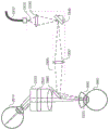
The beam 2210 follows the optical path of the treatment and visualization laser beam described above with respect to fig. 19, and can be scanned to generate any suitable pattern. Beam 2215 can also be scanned to produce any suitable pattern. Light beam 2215 is directed to intersect light beam 2210 at or about the treatment beam waist. As described further below, the intersection of beam 2210 with beam 2215 can thus be used to identify the location of the treatment beam waist and determine whether the treatment beam waist is properly positioned at the tissue to be treated. In the illustrated example, mirror 2220 and lens 2230 are used to direct light beam 2215 to intersect light beam 2210, although any other suitable optical arrangement that produces a desired intersection may also be used. Lens 2230 typically focuses beam 2215 at the intersection of the two beams to a tight waist in order to identify the location of the intersection with greater accuracy.
If the intersection of light beam 2210 with light beam 2215 (and thus the treatment beam waist) is not properly positioned at the treatment tissue, the position of device 2200, or optical elements within the device, can be adjusted relative to the patient's eye to move the intersection of the visualization light beam, and thus the treatment beam waist, to the desired position.
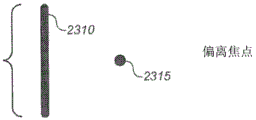
Referring now to fig. 23A-23C, in some variations, beam 2210 is scanned to produce line 2310, and beam 2215 is not scanned but is instead focused to a tight beam waist, which appears as point 2315 in these figures. Apparatus 2200 is aligned (e.g., by the manufacturer) such that beam 2210 intersects beam 2215 at or about the location of the beam waist of the treatment beam, where point 2315 is centered at or about centered on line 2310. Fig. 23A-23C show views of a transmission microscope (e.g., microscope 2000 of fig. 20) of a tissue to be treated (e.g., lens capsule). When the intersection of visualization light beam 2210 and visualization light beam 2215 is not positioned at or about the tissue to be treated, point 2315 and line 2310 will appear to be separate from each other, as shown in fig. 23A-23B. Further, the operator may be able to determine whether the visualization light beams intersect in front of or behind the tissue to be treated based on which side of line 2310 point 2315 appears to be located. After device 2200 is adjusted to position the intersection of light beam 2210 and light beam 2215 (and thus the beam waist of the treatment light beam) at or about the tissue to be treated, line 2310 and point 2315 will appear superimposed, as shown in fig. 23C.
Although the illustrated example uses line 2310 and point 2315, the location of the treatment beam waist relative to the tissue to be treated can be identified and adjusted using any other suitable pattern for intersecting beams 2210 and 2215. Typically, the visualization patterns used in the depth alignment mode are different from those described earlier in this specification. Although in the illustrated example, the intersecting beams 2210 and 2215 are generated by a single visualization laser beam by dithering the scanner 1940, any other suitable method of intersecting visible beams to identify the location of the treatment beam waist may also be used. Light beams 2210 and 2215 may have the same wavelength (as in the example just described) or different wavelengths.
The device 2200 may be switchable between several different operating modes, including the depth alignment mode just described. For example, in some variations, the device 2200 may be switchable between at least the following modes:
● Standby mode: the treatment beam and all visualization beams are turned off.
● depth alignment mode: as described above, the intersecting visualization beams are used to cause the position of the focal point of the treatment beam optical system to be adjusted relative to the position of the tissue to be treated. The therapeutic light beam is not activated.
● ready mode: a visualization pattern is projected onto the lens capsule to guide the treatment. The visualization pattern can facilitate alignment of the treatment beam relative to the anatomy of the eye and/or indicate a desired perimeter of a break to be created with the treatment beam.
● Start (Fire) mode: the treatment laser beam emission is activated and incident on the tissue to be treated.
Referring to fig. 24A, some variations of the device 2200 may include a foot-operable control 2400 in which, for example, a first button 2405 located on the top of the shroud 2410 may be activated to switch from a standby mode to a deep-alignment mode in which the device remains in the deep-alignment mode. Button 2405 may again be activated to switch from the depth alignment mode to the ready mode, where the device remains in the ready mode. When the device is in the ready mode, the shrouded start button 2415 may be activated to switch from the ready mode to the start mode, activating the treatment beam and treatment beam scanning, after which the device returns to the standby mode. Alternatively, button 2405 may be activated again to switch from the ready mode to the standby mode.
Some variations of the device 2220 may also switch into and out of the visualization sizing mode. In the visualization sizing mode, a visualization sizing pattern is projected onto the anterior lens capsule to guide the location of the intended break and thus the location of the intended closed curve of the treatment beam. The size (e.g., diameter or another dimension) of the visualization sizing pattern may be adjusted to increase or decrease the corresponding dimension of the desired break to be formed by the treatment beam. In these variations, for example, the device may switch between modes in the following order: standby mode, deep alignment mode, visualization sizing mode, ready mode, standby mode. This may be done, for example, by sequential activation of buttons 2405 (fig. 24A), as described above. The visualization sizing pattern projected during the visualization sizing mode may have the same geometry as the visualization pattern projected in the ready mode or may be different from the visualization pattern projected in the ready mode. It may be advantageous for the geometry of the visualization sizing pattern to be different from the visualization pattern so that it is easier for the operator to identify which mode the device is in.
Referring to fig. 24B, the foot-operable control 2400 may further include buttons 2420A and 2420B, for example, located on the interior or exterior sidewalls of the shroud, which buttons 2420A and 2420B may be used to increase or decrease the size of the visualization pattern projected during the visualization sizing mode (and correspondingly increase or decrease the desired radius or another dimension of the break to be formed by the treatment beam).
Any other suitable switching mechanism may be used to switch between the operating modes just described. For example, the switching mechanism may be or may include a switch intended to be manually operated. Furthermore, variations of the foot-operable controls 2400 or any other suitable switching mechanism described above may be configured to allow switching of the device from a deep alignment mode to a standby mode, from a visualization sizing mode (if available) to a deep alignment mode, or from a ready mode to a visualization sizing mode (if available) or a deep alignment mode. This may be done, for example, using additional toggle buttons for these transitions or employing a button that reverses the direction in which button 2405 runs the device through the pattern sequence.
Virtual visualization pattern
As described above, the visualization pattern may be projected onto the anterior lens capsule using one or more scanning visualization laser beams to assist in the ophthalmic surgical procedure. As an alternative to such projected visualization patterns, virtual visualization patterns may be presented on the display and overlaid with a view of the anterior lens capsule to assist in the surgical procedure. These patterns are virtual in that they appear as simulated images on the display, but are not actually projected onto the anterior lens capsule. Any of the above-described visualization patterns, and any other suitable visualization patterns, may be presented in this manner as a virtual visualization pattern. Such virtual visualization patterns may be used with respect to the projected visualization pattern for any of the purposes described above. For example, the ready mode of operation and the optional visualization sizing modes of operation described above may employ a virtual visualization pattern instead of a projected visualization pattern. Thus, for example, variations of the treatment devices described herein may employ a treatment laser beam, but lack the collinear visualization laser beam described with respect to fig. 19.
For example, fig. 25 shows a laser scanning treatment device 2500 similar to that of fig. 19 integrated externally with a microscope 2510. Microscope 2510 includes a head-up display 2520 on which a virtual visualization pattern may overlay a microscope-through view of the surgical field to which treatment light beam 1920 is directed. Device 2500 can optionally provide a visualization beam in-line with treatment beam 1920 to also provide a projected visualization pattern, although this is not required. The device 2500 may be integrated internally with a microscope employing a head-up display to present a virtual visualization pattern overlaid with a surgical field, rather than externally as shown in fig. 25. For example, such internal integration may proceed similarly as shown in fig. 22. In addition to displaying one or more virtual visualization patterns overlaid with a surgical field, the heads-up display 2520 may also display data or parameters related to the surgical procedure. For example, the display may report the size or diameter of the fracture corresponding to the displayed virtual visualization pattern and/or the current mode of operation of the treatment device (e.g., standby, depth alignment, visualization sizing, ready, activated, as described above).
Determining the visual axis
In general, it may be desirable to center the disruption to the visual axis of the eye. For example, referring to fig. 19-22 and 25, the visual axis may be determined during an ophthalmic surgical procedure by directing a low power visible laser beam 1920 to the eye and having the patient look at the beam (looking directly at the beam). When the patient fixates on the laser beam, the laser beam is collinear with the visual axis of the patient's eye. Laser beam 1920 may be a treatment beam at low power, for example, a visualization laser beam or another low power visible laser beam. The laser beam may be made to flash at a frequency that is perceivable by the patient (e.g., at less than about 30 hertz) may make it easier for the patient to fixate on the laser beam. For example, the rate of blinking may be randomly varied to further encourage the patient to fixate on the light beam.
This flickering laser beam 1920 may be directed to the eye along or about the optical axis of a microscope used during ophthalmic surgery (e.g., as in fig. 20-22 and 25), such that the position of the visual axis in the surgical field may be viewed through the microscope by an operator and/or with a camera (not shown). The offset of the visual axis from the edge or center of the dilated pupil can be measured thereby if desired. If a virtual visualization pattern is being used on the heads-up display, as described above, the virtual visualization pattern and corresponding treatment beam path may be adjusted to center the break on the visual axis or otherwise adjust the position and/or orientation of the break relative to the visual axis. If the visualization pattern is instead being projected onto the anterior lens capsule with a scanning visualization beam, the visualization pattern and corresponding treatment beam path may be adjusted in a similar manner relative to the visual axis.
Orientation of toric IOLs
The toric IOL has different optical powers and focal lengths along two perpendicular axes. Toric IOLs are typically implanted in a preferred orientation to compensate for astigmatism or other optical aberrations in the eye. The proper orientation of the toric IOL can be determined by using the patient-fixated (optionally blinking) laser beam as described above in the following manner: after the laser beam has passed back through the toric IOL, the reflection of the laser beam from the back of the eye (e.g., the retina) is viewed. The reflections can be viewed through the microscope (as in fig. 20-22 and 25, for example) directly by an observer or with a camera (not shown). If the toric IOL is not properly oriented, the reflection from the back of the eye as viewed through the toric surface will be weaker and have an elliptical shape. If the toric IOL is oriented correctly, the reflection from the back of the eye will be stronger and will appear as a smaller and more circular spot.
The view of the reflection of the laser beam from the back of the eye can be enhanced by using a linearly polarized laser beam and looking through the orthogonal polarizer at the reflection from the back of the eye. The reflection of the laser beam from the anterior surface of the eye (e.g., the cornea) and from the IOL will tend to preserve the linear polarization of the incident laser beam. Reflections from the back of the eye, which would be less polarized than the incident laser beam, may be better described as scattered light rather than reflected light. Thus, the cross-polarizer will tend to repel most of the reflection from the anterior surface of the eye and from the IOL, while passing most of the light reflected or scattered from the back of the eye.
Eye tracking
The devices and methods described above can be employed to track the position of the pupil or other features of the eye by imaging the eye with a camera under infrared illumination. Changes in eye position during ophthalmic surgery (either before or during use of the treatment laser beam) can be fed back to the control system for the scanning laser treatment device to adjust the aim of the treatment laser accordingly.
Detecting light absorbers
In variations of the process described herein in which a light absorbing agent is used to facilitate laser-assisted thermal tissue separation to form an opening in the anterior lens capsule, it may be desirable to optically or visually confirm that the light absorbing agent has been properly placed prior to performing the treatment. In particular, it may be desirable to confirm that sufficient light absorber is present on or in the capsule to prevent transmission of the therapeutic light beam through the capsule at a level that can damage the retina or other portions of the interior of the eye. It may also be desirable to confirm that sufficient light absorber is present on or in the balloon to produce complete thermal separation of the balloon along the treatment beam path.
Unsafe transmission of the treatment beam through the capsule may occur if the intensity of the treatment beam incident on the treated tissue is above a predetermined threshold deemed safe for the retina, and for the speed (dwell time) at which the treatment beam is scanned over the treated tissue, there is insufficient light absorber in the treated tissue to absorb sufficient treatment beam light to reduce the intensity of the treatment beam transmitted through the treated tissue below the safe threshold. Unsafe transmission of the treatment beam through the capsule may also occur if the treatment beam intensity incident on the treated tissue is above a predetermined threshold deemed safe for the retina, and the treatment beam intensity and scanning speed cause thermal tissue separation to occur or to be completed at the location on which the treatment beam is still incident. Preferably, the thermal tissue separation occurs at or reaches completion at a particular location on the treatment beam path after the treatment beam has scanned across that location.
For example, unsafe transmission of a therapeutic light beam through the balloon may be prevented by: placing a sufficient amount of a light absorbing agent on the tissue to be treated; the therapeutic beam scanning speed is selected to be sufficiently fast; and/or the intensity of the treatment beam (determined by power and spot size) incident on the treated tissue is selected to be sufficiently low.
For example, fig. 26A shows an oscilloscope trace for a measurement in which a laser beam having a wavelength of about 577 nanometers and a power suitable for a treatment beam is focused on the anterior lens capsule (from a cadaver) to a fixed spot having a diameter of about 200 microns for about 450 milliseconds. The anterior lens capsule has been treated with trypan blue, a light absorbing agent. The horizontal axis of the oscilloscope traces represents time and the vertical axis represents the transmittance of the treatment beam through the balloon, with the transmittance increasing in a downward direction along the vertical axis. For clarity, the data of fig. 26A is also presented in the transmittance versus time graph of fig. 26B, where the transmittance increases in an upward direction along the vertical axis.
As these figures show, in the case of this measurement, the transmittance of the treatment beam through the lens capsule first slowly increases over time, and then levels off at about 20%, followed by an abrupt transition (breakthrough) to a much higher transmittance that occurs at about 80 milliseconds. For example, a scanning treatment beam having the same wavelength, power, and spot size may have a dwell time of less than or equal to about 60 milliseconds at any given location of the treatment beam path, in which case no "breakthrough" will occur during scanning.
For example, the amount of light absorbing agent present on or in the lens capsule can be assessed by measuring the reflection of broadband (e.g., white) light from the lens capsule and, optionally, the iris, scleral region, and/or surgical contact lens. Broadband light may be provided using conventional microscope illumination, for example, in conjunction with the microscope integrated with the treatment device described above, and the intensity of the reflection of the broadband light may be measured, for example, with a conventional still or video camera integrated with the microscope. For example, a conventional computer may be employed to analyze the image of the reflected light. Additionally or alternatively, light absorbers can be evaluated by similarly measuring the intensity of the reflection of a narrow band detection laser beam from the lens capsule and (optionally) the iris, scleral region, and/or surgical contact lens. For example, in the treatment devices described above, the detection laser beam may be provided through the same optical fiber that delivers the treatment and visualization beams. For example, a visualization pattern laser may provide a detection laser beam. For example, the detection laser may be scanned along the treatment path to determine the presence and amount of light absorbing agents on the treatment path.
Depending on the wavelength at which the reflectance measurement is made, the light absorbing agent (when present in or on the balloon) may affect the reflection from the balloon by absorbing light and thus reducing the reflection from the balloon or by reflecting light more strongly than the balloon tissue and thus increasing the reflection from the balloon. (light absorbers absorb more strongly than the capsular tissue at the treatment wavelength, but are more reflective than the capsular tissue at other wavelengths). In either case, reflectance measurements can be used to assess the amount of light absorber present on or in the capsules.
The reflectance measurements can be made before the light absorbing agent is introduced into the lens capsule and after the light absorbing agent is introduced into the lens capsule. As discussed further below, this may allow for the determination of a background corrected relative reflectance due to the light absorber, for example, by determining a difference between the intensities of the reflections from the capsules measured before and after the light absorber is applied to the capsules. Typically, the light absorbing agent is not applied to the iris, scleral region and any surgical contact lens used and therefore should not affect the reflections from the iris, scleral region and surgical contact lens. Thus, as discussed further below, the reflection intensity from the capsule may be adjusted (e.g., normalized, scaled, or background corrected) using the reflections from the iris, scleral region, and surgical contact lens measured before and after the light absorbing agent is applied to the capsule. For example, these adjustments may compensate for small changes in the orientation of the eye that occur between the "before" and "after" measurements or for other differences in the reflectance measurements that are not related to the application of the light absorbing agent. The "before" and "after" measurements of the intensity of the reflections from the iris, scleral region, and surgical contact lens may also allow the determination of the absolute reflectivity due to light absorbing agents on or in the capsule.
Fig. 27A shows an example image and fig. 27B shows a graph of relative reflectance illustrating a decrease in relative reflectance of broadband illumination from the lens capsule with increasing amount of light absorbing agent applied to the capsule. Similarly, fig. 28A shows an example image and fig. 28B shows a graph of relative reflectance illustrating the relative reflectance of narrow band (red) visualization laser illumination from the lens capsule decreasing with increasing amount of light absorber applied to the capsule.
In some variations, a computer-implemented automated anatomical recognition algorithm identifies a capsular region and optionally an iris and/or sclera region of an image of broadband light reflected from the eye prior to applying a light absorbing agent to the capsular. Red, green and/or blue reflectance intensity values, optionally spatially averaged, are determined in the capsular region of the image and optionally in the iris and/or sclera region of the image. The bright areas of the image where the light detector (e.g., camera) may be saturated are processed independently and may or may not be used. The automatic recognition algorithm may adjust the illumination level to ensure accurate capsule identification and reflectance measurements and optionally to reduce the saturation region. Similarly, a computer-implemented automated anatomical recognition algorithm identifies the capsular region and optionally the iris and/or sclera region of an image of the broadband light reflected from the eye after the light absorbing agent is applied to the capsular. Red, green and/or blue reflectance intensity values, optionally spatially averaged, are determined in the capsular region of the image and optionally in the iris and/or sclera region of the image. The bright areas of the image where the light detector (e.g., camera) may be saturated are processed independently and may or may not be used. The automatic recognition algorithm may adjust the illumination level to ensure accurate capsule identification and reflectance measurements and optionally to reduce the saturation region.
The relative reflectivity of the capsule with respect to the red, green and/or blue color of the iris may be calculated from the measured intensities for both the "before" and "after" images. Alternatively or additionally, the relative reflectivity of the capsule with respect to the red, green and/or blue of the scleral region may be calculated from the intensities measured for both the "before" and "after" images. Alternatively or additionally, the relative reflectivity of the capsules for red, green and/or blue with respect to the average total intensity of the images may be calculated from the measured intensities for both the "before" and "after" images. Alternatively or additionally, the relative reflectivity of the capsules for red, green, and/or blue at a fixed illumination intensity may be calculated from the measured intensities for both the "before" and "after" images. These individual determined reflectance values can be used to assess the amount of light absorber present in or on the capsules.
In other variations, a computer-implemented automated anatomical recognition algorithm identifies the capsular region and optionally the iris and/or sclera region of an image of the narrow band (e.g., detection laser) light reflected from the eye prior to applying the light absorbing agent to the capsule. An optionally spatially averaged reflection intensity value is determined in the capsular region of the image and optionally in the iris and/or sclera region of the image. The bright areas of the image where the light detector (e.g., camera) may be saturated are processed independently and may or may not be used. The automatic recognition algorithm may adjust the illumination level to ensure accurate capsule identification and reflectance measurements and optionally to reduce the saturation region. Similarly, a computer-implemented automated anatomical recognition algorithm identifies the capsular region and optionally the iris and/or sclera region of the narrow band (e.g., detection laser) light reflected from the eye after the light absorbing agent is applied to the capsule. An optionally spatially averaged reflection intensity value is determined in the capsular region of the image and optionally in the iris and/or sclera region of the image. The bright areas of the image where the light detector (e.g., camera) may be saturated are processed independently and may or may not be used. The automatic recognition algorithm may adjust the illumination level to ensure accurate capsule identification and reflectance measurements and optionally to reduce the saturation region.
The relative reflectivity of the capsule with respect to the iris may be calculated from the measured intensities for both the "before" and "after" images. Alternatively or additionally, the relative reflectivity of the capsule with respect to the scleral region may be calculated from the intensities measured for both the "before" and "after" images. Alternatively or additionally, the relative reflectivity of the capsules with respect to the average total intensity of the images may be calculated from the measured intensities for both the "before" and "after" images. Alternatively or additionally, the relative reflectivity for a fixed illumination intensity may be calculated from the measured intensities for both the "before" and "after" images. These individual determined reflectance values can be used to assess the amount of light absorber present in or on the capsules.
In the reflectance measurement and analysis method just described, automated anatomical recognition of microscopic views of the iris, capsule, and sclera can be implemented by analyzing the images to determine the three primary regions. The approximately circular main area represents the capsule or pupil and typically has a diameter of about 4mm to about 12 mm. The second region is an approximately circular band concentric with the main region and typically has a width of about 0.5mm to about 5 mm. This second region represents the iris. The color texture of the image for this region may come from the reflection of structured pigmented tissue and may be used in automated recognition. The third region is concentric with the primary and secondary regions and represents the sclera. This area effectively reflects the illumination light and may have structured blood vessels that can be used in automated recognition.
If the light absorber absorbs light at the wavelength at which the relative reflectance is measured, the relative reflectance measurement will be positively correlated with the transmission of the treatment beam through the balloon. That is, when the amount of light absorber in the capsule is increased, both the relative reflectivity (e.g., of the detection laser or of the component of the broadband illumination) and the transmittance of the treatment beam will decrease. An example of this is shown, for example, in the graphs of fig. 29 and 30.
For example, this correlation between relative reflectance and treatment beam transmittance may be measured on the eyes of cadavers and then used to inform or control treatment of a living patient.
For example, safe treatment may require that the transmittance of the treatment beam through the balloon be less than some predetermined threshold value, which is related to a particular threshold relative reflectance value. In fig. 30, for example, the 20% transmittance threshold corresponds to the 60% relative reflectance threshold. If the relative reflectance measured of the patient's eye after the light absorber has been dispensed is less than the threshold reflectance value, the transmittance of the treatment beam through the balloon is below the allowed limit and treatment may continue. If the relative reflectance is too high, additional light absorber can be dispensed, for example, until the relative reflectance is measured at or below a threshold relative reflectance value.
Alternatively or additionally, after the light absorber has been dispensed, the treatment parameters (e.g., treatment laser power, wavelength, spot size, and/or scan speed) may be selected and/or controlled based on the relative reflectance measurements such that the treatment is performed in an optimal manner and the transmittance of the treatment beam through the capsule remains below a predetermined threshold throughout the treatment. For example, the treatment device may utilize a lookup table that maps treatment parameters onto reflectance measurements.
For example, reflectance measurements can also be used to confirm that sufficient light absorber is present along the treatment beam path to produce complete laser thermal separation of the anterior capsule upon application of selected/preprogrammed treatment beam parameters. This may be accomplished, for example, by analyzing (e.g., as described above) the image in the region that includes the complete treatment path to ensure that the reflectance is below a predetermined (e.g., preprogrammed) value along the entire path.
In an alternative method, the light absorbing agent can be detected by exciting and detecting fluorescence from the light absorbing agent. This may be done, for example, using a treatment beam or an attenuated portion of a treatment beam. This measurement can optionally be made remote from the treatment location to avoid loss of the light absorber required for the treatment scan. For example, fluorescence indicative of the presence of light absorbers can be observed or detected through a microscope integrated with the treatment device as described above.
The present invention is illustrative and not restrictive. Other modifications will be apparent to those skilled in the art in view of this disclosure and are intended to be within the scope of the appended claims. For example, in some variations, pulsed lasers may be used in place of continuous wave lasers in the methods and devices described above to generate visualization and/or treatment laser beams. Further, although the treatment beam is described above as producing thermal tissue separation along a closed curve without ablating anterior lens capsule tissue, the devices and methods described herein may alternatively employ a treatment beam that causes tissue separation along a closed curve, for example, by other laser-induced mechanisms (e.g., laser-induced tissue ablation). In particular, the various treatment beam patterns, projected and virtual visualization patterns, methods for determining the visual axis of the eye, methods for assessing the orientation of a toric IOL, and related methods and devices described herein may be used with treatment lasers that produce separation of the anterior lens tissue along a closed path by any suitable mechanism.
Claims (24)
1. An apparatus for forming an opening in the anterior lens capsule of an eye, the apparatus comprising:
a treatment laser outputting a treatment laser beam;
a two-dimensional scanner on which the therapeutic laser beam is incident;
a scanner controller that controls the two-dimensional scanner, the scanner controller having one or more programmed scan profiles for a predetermined treatment pattern at which the treatment laser beam is scanned to form a closed curve at the anterior lens capsule; and
a display programmed to display one or more virtual visualization patterns of a view of a surgical field to which the treatment laser beam overlying the anterior lens capsule is directed, each programmed scan profile for the treatment laser beam having a corresponding programmed virtual visualization pattern;
wherein the wavelength of the treatment laser beam is selected to be very strongly absorbed at the anterior lens capsule and the power is selected to cause thermal denaturation of collagen in the anterior lens capsule producing thermal tissue separation along the closed curve to form the opening without ablating anterior lens capsule tissue; and
wherein, for each programmed scan profile for the treatment laser beam, at least a portion of the respective programmed virtual visualization pattern represents and matches a size and a position of a peripheral boundary of the opening to be created in the anterior lens capsule by the treatment laser beam, the peripheral boundary of the opening differing in size and position from the closed curve of a respective predetermined treatment pattern and having a larger diameter than the respective predetermined treatment pattern.
2. The device of claim 1, wherein the wavelength of the treatment laser beam comprises a wavelength absorbed by trypan blue or indocyanine green, wherein treatment laser beam power is 300mW to 3000mW, and wherein the power is selected to have an absorbance at the anterior lens capsule of 35% or more of the treatment laser beam power.
3. The device of claim 1, wherein at least a portion of the virtual visualization pattern matches a pupil or limbus of the eye and thereby facilitates alignment of the predetermined treatment pattern relative to those anatomical features.
4. The device of claim 1, wherein the treatment laser beam has a spot size at the anterior lens capsule of greater than or equal to 50 microns to less than or equal to 300 microns.
5. The device of claim 1, wherein the treatment laser beam is a continuous wave laser, the treatment laser beam is scanned in a single pass along the closed curve of the predetermined treatment pattern, and treatment laser beam power is constant along the closed curve.
6. The apparatus of claim 1, wherein scanning the treatment laser beam is completed in less than or equal to 10 seconds.
7. The apparatus of claim 6, wherein scanning the treatment laser beam is completed in less than or equal to 5 seconds.
8. The apparatus of claim 7, wherein scanning the treatment laser beam is completed in less than or equal to 1 second.
9. The device of claim 1, wherein the treatment laser beam is focused to a beam waist at the anterior lens capsule and diverges as the treatment laser beam is incident on a retina of the eye, and the predetermined treatment pattern diverges in the eye and is thus expanded in size and area on the retina as compared to the size and area of the treatment pattern at the anterior lens capsule.
10. The device of claim 9, wherein the treatment laser beam provides less than or equal to 2000J/cm at the anterior lens capsule along the closed curve of the predetermined treatment pattern2And provide less than or equal to 10J/cm on the retina of the eye along a corresponding closed curve2The fluence of (2).
11. The device of claim 9, wherein the treatment laser beam provides less than or equal to 10,000W/cm at the anterior lens capsule along the closed curve of the predetermined treatment pattern2And provide less than or equal to 400mW/cm on the retina of the eye along a corresponding closed curve2Peak irradiance of.
12. The device of claim 9, wherein the treatment laser beam has a diameter of greater than or equal to 100 microns to less than or equal to 300 microns at the anterior lens capsule.
13. The device of claim 9, wherein the therapeutic pattern on the retina avoids the fovea of the eye.
14. The apparatus of claim 1, wherein at the beginning of the predetermined treatment pattern, treatment laser beam power is ramped from 0 to 90% of its full power during a period of 5 milliseconds to 200 milliseconds.
15. The device of claim 14, wherein the treatment laser beam is scanned from an initial point inside the closed curve toward the closed curve at a speed less than an average speed at which the treatment laser beam is subsequently scanned along the closed curve, and the ramping up of treatment laser beam power is completed before the treatment laser beam reaches the closed curve.
16. The apparatus of claim 2, comprising a detection laser outputting a detection laser beam having a wavelength that is reflected by trypan blue or indocyanine green.
17. The device of claim 2, comprising a detection laser that outputs a detection laser beam having a wavelength that excites fluorescence from trypan blue or indocyanine green.
18. The apparatus of claim 2, comprising a broadband light source that outputs broadband illumination reflected by trypan blue or indocyanine green.
19. The device of claim 18, wherein the broadband illumination is white light.
20. The device of claim 13, arranged in combination with a surgical contact lens positioned on the eye to counteract a focusing power of a cornea of the eye on the retina of the eye and refract a scan pattern away from the fovea of the eye.
21. The device of claim 1, comprising a laser that outputs a visible light laser beam that flashes at a frequency perceptible to a human patient, is directed into the eye, and establishes a visual axis of the eye upon the patient gazing at the visible light laser beam.
22. The apparatus of claim 21, wherein the predetermined treatment pattern is centered on the visual axis determined by the flashing visible light laser beam.
23. The device of claim 1 integrated with a microscope.
24. The device of claim 1, integrated with an aberrometer configured to measure refractive properties of the eye.
Applications Claiming Priority (13)
| Application Number | Priority Date | Filing Date | Title |
|---|---|---|---|
| US14/193,716 US20150245945A1 (en) | 2014-02-28 | 2014-02-28 | Laser assisted cataract surgery |
| US14/193,630 | 2014-02-28 | ||
| US14/193,592 | 2014-02-28 | ||
| US14/193,716 | 2014-02-28 | ||
| US14/193,630 US9820886B2 (en) | 2014-02-28 | 2014-02-28 | Laser assisted cataract surgery |
| US14/193,671 US10231872B2 (en) | 2014-02-28 | 2014-02-28 | Laser assisted cataract surgery |
| US14/193,671 | 2014-02-28 | ||
| US14/193,592 US10206817B2 (en) | 2014-02-28 | 2014-02-28 | Laser assisted cataract surgery |
| US201461975506P | 2014-04-04 | 2014-04-04 | |
| US61/975,506 | 2014-04-04 | ||
| US201462047373P | 2014-09-08 | 2014-09-08 | |
| US62/047,373 | 2014-09-08 | ||
| CN201580016670.5A CN106163467B (en) | 2014-02-28 | 2015-02-27 | Laser assisted cataract operation |
Related Parent Applications (1)
| Application Number | Title | Priority Date | Filing Date |
|---|---|---|---|
| CN201580016670.5A Division CN106163467B (en) | 2014-02-28 | 2015-02-27 | Laser assisted cataract operation |
Publications (2)
| Publication Number | Publication Date |
|---|---|
| CN109124871A CN109124871A (en) | 2019-01-04 |
| CN109124871B true CN109124871B (en) | 2021-11-02 |
Family
ID=54009682
Family Applications (3)
| Application Number | Title | Priority Date | Filing Date |
|---|---|---|---|
| CN201810782796.9A Active CN109124871B (en) | 2014-02-28 | 2015-02-27 | Laser assisted cataract surgery |
| CN202111202845.5A Pending CN113925677A (en) | 2014-02-28 | 2015-02-27 | Laser assisted cataract surgery |
| CN201580016670.5A Active CN106163467B (en) | 2014-02-28 | 2015-02-27 | Laser assisted cataract operation |
Family Applications After (2)
| Application Number | Title | Priority Date | Filing Date |
|---|---|---|---|
| CN202111202845.5A Pending CN113925677A (en) | 2014-02-28 | 2015-02-27 | Laser assisted cataract surgery |
| CN201580016670.5A Active CN106163467B (en) | 2014-02-28 | 2015-02-27 | Laser assisted cataract operation |
Country Status (7)
| Country | Link |
|---|---|
| EP (1) | EP3110378B1 (en) |
| JP (1) | JP6480475B2 (en) |
| CN (3) | CN109124871B (en) |
| AU (1) | AU2015222738B2 (en) |
| CA (1) | CA2940307C (en) |
| ES (1) | ES2749380T3 (en) |
| WO (1) | WO2015131135A1 (en) |
Families Citing this family (5)
| Publication number | Priority date | Publication date | Assignee | Title |
|---|---|---|---|---|
| US11298265B2 (en) | 2016-10-24 | 2022-04-12 | Excel-Lens, Inc. | Intraocular lens with tilted optical axis |
| ES2941994T3 (en) * | 2017-10-17 | 2023-05-29 | Alcon Inc | Custom ophthalmic surgical profiles |
| GB2603006A (en) * | 2021-01-26 | 2022-07-27 | Edinburgh Biosciences Ltd | Apparatus and systems for monitoring and treating cataracts |
| WO2023062650A1 (en) | 2021-10-14 | 2023-04-20 | Appasamy Associates Pvt Ltd | SINGLE AND/OR DUAL (532 AND/OR 577) nm LASER DELIVERY SYSTEM ATTACHED TO AN OPHTHALMIC MICROSCOPE |
| WO2023089396A1 (en) * | 2021-11-19 | 2023-05-25 | Alcon Inc. | Improved visualization of vitreous floaters in the eye |
Citations (11)
| Publication number | Priority date | Publication date | Assignee | Title |
|---|---|---|---|---|
| US4538608A (en) * | 1984-03-23 | 1985-09-03 | Esperance Jr Francis A L | Method and apparatus for removing cataractous lens tissue by laser radiation |
| US4580559A (en) * | 1984-07-24 | 1986-04-08 | Esperance Francis A L | Indirect ophthalmoscopic photocoagulation delivery system for retinal surgery |
| EP1759672A1 (en) * | 2005-08-31 | 2007-03-07 | Alcon, Inc. | Controlling a phacoemulsification surgical system by transitioning between pulse and burst modes |
| CN101431957A (en) * | 2004-09-09 | 2009-05-13 | 雷利恩特技术公司 | Interchangeable tips for medical laser treatments and methods for using same |
| CN102791228A (en) * | 2010-01-08 | 2012-11-21 | 眼科医疗公司 | System for modifying eye tissue and intraocular lenses |
| CN102811684A (en) * | 2010-01-22 | 2012-12-05 | 眼科医疗公司 | Apparatus for automated placement of scanned laser capsulorhexis incisions |
| CN103025283A (en) * | 2010-06-24 | 2013-04-03 | 爱尔康手术激光股份有限公司 | Method to guide a cataract procedure by corneal imaging |
| CN103037821A (en) * | 2010-06-24 | 2013-04-10 | 爱尔康手术激光股份有限公司 | Method and apparatus for integrating cataract surgery with glaucoma or astigmatism surgery |
| EP2059202B1 (en) * | 2006-09-05 | 2013-08-14 | AMO Development, LLC | System for marking corneal tissue in a transplant procedure |
| CN103517691A (en) * | 2011-03-30 | 2014-01-15 | 光线激光器有限公司 | Apparatus for treating an eye using a laser beam |
| CN103536390A (en) * | 2005-01-10 | 2014-01-29 | 光学医疗公司 | Method and apparatus for patterned plasma-mediated laser trephination of the lens capsule and three dimensional phaco-segmentation |
Family Cites Families (12)
| Publication number | Priority date | Publication date | Assignee | Title |
|---|---|---|---|---|
| US6033396A (en) * | 1995-11-06 | 2000-03-07 | Huang; David | Apparatus and method for performing laser thermal keratoplasty with minimized regression |
| JP2000060893A (en) * | 1998-08-20 | 2000-02-29 | Kowa Co | Ophthalmological treatment device |
| WO2003068051A2 (en) * | 2002-02-12 | 2003-08-21 | Visx, Inc. | Flexible scanning beam imaging system |
| US6964659B2 (en) * | 2002-05-30 | 2005-11-15 | Visx, Incorporated | Thermal modeling for reduction of refractive laser surgery times |
| DE10331792A1 (en) * | 2003-07-11 | 2005-02-17 | Medizinisches Laserzentrum Lübeck GmbH | Laser with dose rate control |
| US7619171B2 (en) * | 2005-06-30 | 2009-11-17 | Alcon, Inc. | Multifunction surgical footswitch |
| US10842675B2 (en) * | 2006-01-20 | 2020-11-24 | Lensar, Inc. | System and method for treating the structure of the human lens with a laser |
| CN101631522B (en) * | 2007-03-13 | 2014-11-05 | 眼科医疗公司 | Apparatus for creating ocular surgical and relaxing incisions |
| US8016420B2 (en) * | 2007-05-17 | 2011-09-13 | Amo Development Llc. | System and method for illumination and fixation with ophthalmic diagnostic instruments |
| JP2010538770A (en) * | 2007-09-18 | 2010-12-16 | アルコン レンゼックス, インコーポレーテッド | Method and apparatus for integrated cataract surgery |
| US8409182B2 (en) * | 2007-09-28 | 2013-04-02 | Eos Holdings, Llc | Laser-assisted thermal separation of tissue |
| US20110184395A1 (en) * | 2009-12-23 | 2011-07-28 | Optimedica Corporation | Method for laser capsulotomy and lens conditioning |
-
2015
- 2015-02-27 AU AU2015222738A patent/AU2015222738B2/en active Active
- 2015-02-27 CN CN201810782796.9A patent/CN109124871B/en active Active
- 2015-02-27 WO PCT/US2015/018158 patent/WO2015131135A1/en active Application Filing
- 2015-02-27 EP EP15754864.5A patent/EP3110378B1/en active Active
- 2015-02-27 JP JP2016572367A patent/JP6480475B2/en active Active
- 2015-02-27 ES ES15754864T patent/ES2749380T3/en active Active
- 2015-02-27 CN CN202111202845.5A patent/CN113925677A/en active Pending
- 2015-02-27 CA CA2940307A patent/CA2940307C/en active Active
- 2015-02-27 CN CN201580016670.5A patent/CN106163467B/en active Active
Patent Citations (11)
| Publication number | Priority date | Publication date | Assignee | Title |
|---|---|---|---|---|
| US4538608A (en) * | 1984-03-23 | 1985-09-03 | Esperance Jr Francis A L | Method and apparatus for removing cataractous lens tissue by laser radiation |
| US4580559A (en) * | 1984-07-24 | 1986-04-08 | Esperance Francis A L | Indirect ophthalmoscopic photocoagulation delivery system for retinal surgery |
| CN101431957A (en) * | 2004-09-09 | 2009-05-13 | 雷利恩特技术公司 | Interchangeable tips for medical laser treatments and methods for using same |
| CN103536390A (en) * | 2005-01-10 | 2014-01-29 | 光学医疗公司 | Method and apparatus for patterned plasma-mediated laser trephination of the lens capsule and three dimensional phaco-segmentation |
| EP1759672A1 (en) * | 2005-08-31 | 2007-03-07 | Alcon, Inc. | Controlling a phacoemulsification surgical system by transitioning between pulse and burst modes |
| EP2059202B1 (en) * | 2006-09-05 | 2013-08-14 | AMO Development, LLC | System for marking corneal tissue in a transplant procedure |
| CN102791228A (en) * | 2010-01-08 | 2012-11-21 | 眼科医疗公司 | System for modifying eye tissue and intraocular lenses |
| CN102811684A (en) * | 2010-01-22 | 2012-12-05 | 眼科医疗公司 | Apparatus for automated placement of scanned laser capsulorhexis incisions |
| CN103025283A (en) * | 2010-06-24 | 2013-04-03 | 爱尔康手术激光股份有限公司 | Method to guide a cataract procedure by corneal imaging |
| CN103037821A (en) * | 2010-06-24 | 2013-04-10 | 爱尔康手术激光股份有限公司 | Method and apparatus for integrating cataract surgery with glaucoma or astigmatism surgery |
| CN103517691A (en) * | 2011-03-30 | 2014-01-15 | 光线激光器有限公司 | Apparatus for treating an eye using a laser beam |
Also Published As
| Publication number | Publication date |
|---|---|
| EP3110378B1 (en) | 2019-08-07 |
| CN109124871A (en) | 2019-01-04 |
| WO2015131135A1 (en) | 2015-09-03 |
| EP3110378A4 (en) | 2017-11-29 |
| JP6480475B2 (en) | 2019-03-13 |
| CA2940307A1 (en) | 2015-09-03 |
| AU2015222738A1 (en) | 2016-09-08 |
| CN106163467A (en) | 2016-11-23 |
| ES2749380T3 (en) | 2020-03-20 |
| EP3110378A1 (en) | 2017-01-04 |
| JP2017506573A (en) | 2017-03-09 |
| CN113925677A (en) | 2022-01-14 |
| CA2940307C (en) | 2022-07-12 |
| CN106163467B (en) | 2018-08-10 |
| AU2015222738B2 (en) | 2020-05-14 |
Similar Documents
| Publication | Publication Date | Title |
|---|---|---|
| US20200390597A1 (en) | Method and system for modifying eye tissue and intraocular lenses | |
| US10864114B2 (en) | Method and system for modifying eye tissue and intraocular lenses | |
| US20200155352A1 (en) | Laser assisted cataract surgery | |
| US20140350533A1 (en) | Contactless photodisruptive laser cataract surgery | |
| CN109124871B (en) | Laser assisted cataract surgery | |
| CA2994799C (en) | Method and system for modifying eye tissue and intraocular lenses | |
| US11298265B2 (en) | Intraocular lens with tilted optical axis | |
| US10206817B2 (en) | Laser assisted cataract surgery | |
| US9820886B2 (en) | Laser assisted cataract surgery | |
| US10231872B2 (en) | Laser assisted cataract surgery | |
| US11786404B2 (en) | Laser assisted cataract surgery | |
| US20150245945A1 (en) | Laser assisted cataract surgery |
Legal Events
| Date | Code | Title | Description |
|---|---|---|---|
| PB01 | Publication | ||
| PB01 | Publication | ||
| SE01 | Entry into force of request for substantive examination | ||
| SE01 | Entry into force of request for substantive examination | ||
| GR01 | Patent grant | ||
| GR01 | Patent grant |