CN109120927B - Image decoding device, image decoding method, and image encoding device - Google Patents
Image decoding device, image decoding method, and image encoding device Download PDFInfo
- Publication number
- CN109120927B CN109120927B CN201810874148.6A CN201810874148A CN109120927B CN 109120927 B CN109120927 B CN 109120927B CN 201810874148 A CN201810874148 A CN 201810874148A CN 109120927 B CN109120927 B CN 109120927B
- Authority
- CN
- China
- Prior art keywords
- frequency
- context
- decoding
- unit
- syntax
- Prior art date
- Legal status (The legal status is an assumption and is not a legal conclusion. Google has not performed a legal analysis and makes no representation as to the accuracy of the status listed.)
- Active
Links
Images


Classifications
-
- H—ELECTRICITY
- H04—ELECTRIC COMMUNICATION TECHNIQUE
- H04N—PICTORIAL COMMUNICATION, e.g. TELEVISION
- H04N19/00—Methods or arrangements for coding, decoding, compressing or decompressing digital video signals
- H04N19/10—Methods or arrangements for coding, decoding, compressing or decompressing digital video signals using adaptive coding
- H04N19/169—Methods or arrangements for coding, decoding, compressing or decompressing digital video signals using adaptive coding characterised by the coding unit, i.e. the structural portion or semantic portion of the video signal being the object or the subject of the adaptive coding
- H04N19/17—Methods or arrangements for coding, decoding, compressing or decompressing digital video signals using adaptive coding characterised by the coding unit, i.e. the structural portion or semantic portion of the video signal being the object or the subject of the adaptive coding the unit being an image region, e.g. an object
- H04N19/176—Methods or arrangements for coding, decoding, compressing or decompressing digital video signals using adaptive coding characterised by the coding unit, i.e. the structural portion or semantic portion of the video signal being the object or the subject of the adaptive coding the unit being an image region, e.g. an object the region being a block, e.g. a macroblock
-
- H—ELECTRICITY
- H04—ELECTRIC COMMUNICATION TECHNIQUE
- H04N—PICTORIAL COMMUNICATION, e.g. TELEVISION
- H04N19/00—Methods or arrangements for coding, decoding, compressing or decompressing digital video signals
- H04N19/60—Methods or arrangements for coding, decoding, compressing or decompressing digital video signals using transform coding
-
- H—ELECTRICITY
- H04—ELECTRIC COMMUNICATION TECHNIQUE
- H04N—PICTORIAL COMMUNICATION, e.g. TELEVISION
- H04N19/00—Methods or arrangements for coding, decoding, compressing or decompressing digital video signals
- H04N19/10—Methods or arrangements for coding, decoding, compressing or decompressing digital video signals using adaptive coding
- H04N19/102—Methods or arrangements for coding, decoding, compressing or decompressing digital video signals using adaptive coding characterised by the element, parameter or selection affected or controlled by the adaptive coding
- H04N19/117—Filters, e.g. for pre-processing or post-processing
-
- H—ELECTRICITY
- H04—ELECTRIC COMMUNICATION TECHNIQUE
- H04N—PICTORIAL COMMUNICATION, e.g. TELEVISION
- H04N19/00—Methods or arrangements for coding, decoding, compressing or decompressing digital video signals
- H04N19/10—Methods or arrangements for coding, decoding, compressing or decompressing digital video signals using adaptive coding
- H04N19/102—Methods or arrangements for coding, decoding, compressing or decompressing digital video signals using adaptive coding characterised by the element, parameter or selection affected or controlled by the adaptive coding
- H04N19/124—Quantisation
-
- H—ELECTRICITY
- H04—ELECTRIC COMMUNICATION TECHNIQUE
- H04N—PICTORIAL COMMUNICATION, e.g. TELEVISION
- H04N19/00—Methods or arrangements for coding, decoding, compressing or decompressing digital video signals
- H04N19/10—Methods or arrangements for coding, decoding, compressing or decompressing digital video signals using adaptive coding
- H04N19/102—Methods or arrangements for coding, decoding, compressing or decompressing digital video signals using adaptive coding characterised by the element, parameter or selection affected or controlled by the adaptive coding
- H04N19/13—Adaptive entropy coding, e.g. adaptive variable length coding [AVLC] or context adaptive binary arithmetic coding [CABAC]
-
- H—ELECTRICITY
- H04—ELECTRIC COMMUNICATION TECHNIQUE
- H04N—PICTORIAL COMMUNICATION, e.g. TELEVISION
- H04N19/00—Methods or arrangements for coding, decoding, compressing or decompressing digital video signals
- H04N19/10—Methods or arrangements for coding, decoding, compressing or decompressing digital video signals using adaptive coding
- H04N19/134—Methods or arrangements for coding, decoding, compressing or decompressing digital video signals using adaptive coding characterised by the element, parameter or criterion affecting or controlling the adaptive coding
- H04N19/136—Incoming video signal characteristics or properties
- H04N19/137—Motion inside a coding unit, e.g. average field, frame or block difference
- H04N19/139—Analysis of motion vectors, e.g. their magnitude, direction, variance or reliability
-
- H—ELECTRICITY
- H04—ELECTRIC COMMUNICATION TECHNIQUE
- H04N—PICTORIAL COMMUNICATION, e.g. TELEVISION
- H04N19/00—Methods or arrangements for coding, decoding, compressing or decompressing digital video signals
- H04N19/10—Methods or arrangements for coding, decoding, compressing or decompressing digital video signals using adaptive coding
- H04N19/134—Methods or arrangements for coding, decoding, compressing or decompressing digital video signals using adaptive coding characterised by the element, parameter or criterion affecting or controlling the adaptive coding
- H04N19/136—Incoming video signal characteristics or properties
- H04N19/14—Coding unit complexity, e.g. amount of activity or edge presence estimation
-
- H—ELECTRICITY
- H04—ELECTRIC COMMUNICATION TECHNIQUE
- H04N—PICTORIAL COMMUNICATION, e.g. TELEVISION
- H04N19/00—Methods or arrangements for coding, decoding, compressing or decompressing digital video signals
- H04N19/10—Methods or arrangements for coding, decoding, compressing or decompressing digital video signals using adaptive coding
- H04N19/134—Methods or arrangements for coding, decoding, compressing or decompressing digital video signals using adaptive coding characterised by the element, parameter or criterion affecting or controlling the adaptive coding
- H04N19/157—Assigned coding mode, i.e. the coding mode being predefined or preselected to be further used for selection of another element or parameter
- H04N19/159—Prediction type, e.g. intra-frame, inter-frame or bidirectional frame prediction
-
- H—ELECTRICITY
- H04—ELECTRIC COMMUNICATION TECHNIQUE
- H04N—PICTORIAL COMMUNICATION, e.g. TELEVISION
- H04N19/00—Methods or arrangements for coding, decoding, compressing or decompressing digital video signals
- H04N19/10—Methods or arrangements for coding, decoding, compressing or decompressing digital video signals using adaptive coding
- H04N19/169—Methods or arrangements for coding, decoding, compressing or decompressing digital video signals using adaptive coding characterised by the coding unit, i.e. the structural portion or semantic portion of the video signal being the object or the subject of the adaptive coding
- H04N19/18—Methods or arrangements for coding, decoding, compressing or decompressing digital video signals using adaptive coding characterised by the coding unit, i.e. the structural portion or semantic portion of the video signal being the object or the subject of the adaptive coding the unit being a set of transform coefficients
-
- H—ELECTRICITY
- H04—ELECTRIC COMMUNICATION TECHNIQUE
- H04N—PICTORIAL COMMUNICATION, e.g. TELEVISION
- H04N19/00—Methods or arrangements for coding, decoding, compressing or decompressing digital video signals
- H04N19/70—Methods or arrangements for coding, decoding, compressing or decompressing digital video signals characterised by syntax aspects related to video coding, e.g. related to compression standards
-
- H—ELECTRICITY
- H04—ELECTRIC COMMUNICATION TECHNIQUE
- H04N—PICTORIAL COMMUNICATION, e.g. TELEVISION
- H04N19/00—Methods or arrangements for coding, decoding, compressing or decompressing digital video signals
- H04N19/90—Methods or arrangements for coding, decoding, compressing or decompressing digital video signals using coding techniques not provided for in groups H04N19/10-H04N19/85, e.g. fractals
- H04N19/91—Entropy coding, e.g. variable length coding [VLC] or arithmetic coding
-
- H—ELECTRICITY
- H04—ELECTRIC COMMUNICATION TECHNIQUE
- H04N—PICTORIAL COMMUNICATION, e.g. TELEVISION
- H04N19/00—Methods or arrangements for coding, decoding, compressing or decompressing digital video signals
- H04N19/10—Methods or arrangements for coding, decoding, compressing or decompressing digital video signals using adaptive coding
- H04N19/169—Methods or arrangements for coding, decoding, compressing or decompressing digital video signals using adaptive coding characterised by the coding unit, i.e. the structural portion or semantic portion of the video signal being the object or the subject of the adaptive coding
- H04N19/17—Methods or arrangements for coding, decoding, compressing or decompressing digital video signals using adaptive coding characterised by the coding unit, i.e. the structural portion or semantic portion of the video signal being the object or the subject of the adaptive coding the unit being an image region, e.g. an object
- H04N19/172—Methods or arrangements for coding, decoding, compressing or decompressing digital video signals using adaptive coding characterised by the coding unit, i.e. the structural portion or semantic portion of the video signal being the object or the subject of the adaptive coding the unit being an image region, e.g. an object the region being a picture, frame or field
-
- H—ELECTRICITY
- H04—ELECTRIC COMMUNICATION TECHNIQUE
- H04N—PICTORIAL COMMUNICATION, e.g. TELEVISION
- H04N19/00—Methods or arrangements for coding, decoding, compressing or decompressing digital video signals
- H04N19/42—Methods or arrangements for coding, decoding, compressing or decompressing digital video signals characterised by implementation details or hardware specially adapted for video compression or decompression, e.g. dedicated software implementation
- H04N19/436—Methods or arrangements for coding, decoding, compressing or decompressing digital video signals characterised by implementation details or hardware specially adapted for video compression or decompression, e.g. dedicated software implementation using parallelised computational arrangements
Abstract
The amount of processing is reduced while maintaining high coding efficiency. The arithmetic decoding device includes syntax decoding means for decoding each of at least 1 st syntax and 2 nd syntax indicating a transform coefficient by context-using arithmetic decoding or non-context-using arithmetic decoding, and the syntax decoding means includes at least the following cases: a case of decoding the 2 nd syntax through the non-context-using arithmetic decoding without decoding the 1 st syntax; and decoding the 1 st syntax by the context-utilized arithmetic decoding, and decoding the 2 nd syntax by the non-context-utilized arithmetic decoding.
Description
The present application is a divisional application No.201280053701.0 entitled "arithmetic decoding device, image decoding device, arithmetic coding device, image coding device, and arithmetic decoding method" filed by the intellectual property office of china on day 31/10/2012.
Technical Field
The present invention relates to an arithmetic decoding device that decodes coded data that has been arithmetically encoded, and an image decoding device provided with such an arithmetic decoding device. The present invention also relates to an arithmetic coding device that generates arithmetic-coded data and an image coding device provided with such an arithmetic coding device. In addition, the present invention relates to an arithmetic decoding method for decoding coded data that has been arithmetically coded.
Background
In order to efficiently transmit or record a moving image, a moving image encoding device (image encoding device) that generates encoded data by encoding a moving image and a moving image decoding device (image decoding device) that generates a decoded image by decoding the encoded data are used.
Specific examples of the Video encoding method include a method used in KTA software as a codec for common development in h.264/MPEG-4. AVC and VCEG (Video Coding Expert Group), a method used in tmuc (test Model under configuration) software, and a method proposed in HEVC (High-Efficiency Video Coding) as a subsequent codec (non-patent document 1).
In such a moving image Coding scheme, images (pictures) constituting a moving image are managed by a hierarchical structure including slices obtained by dividing the images, Coding units (also referred to as Coding units) obtained by dividing the slices, and blocks and partitions obtained by dividing the Coding units, and are usually coded/decoded on a block-by-block basis.
In such an encoding method, a predicted image is generally generated based on a locally decoded image obtained by encoding and decoding an input image, and a difference image (also referred to as a "residual image" or a "prediction residual") between the predicted image and the input image is subjected to frequency transform such as dct (discrete Cosine transform) transform on a block-by-block basis to encode a transform coefficient obtained thereby.
As specific encoding methods of transform coefficients, Context-Adaptive Variable Length Coding (CAVLC) and Context-Adaptive Binary Arithmetic Coding (CABAC) are known.
In CALVC, each transform coefficient is sequentially scanned to form a one-dimensional vector, and then syntax representing the value of each transform coefficient, syntax representing the length of 0 (also referred to as a run length) in succession, and the like are encoded.
In CABAC, binarization processing is performed on various syntaxes representing transform coefficients, and binary data obtained by the binarization processing is arithmetically encoded. Here, as the above-described various syntax, flags indicating whether or not the transform coefficient is 0, that is, flags indicating the presence or absence of a non-0 transform coefficient, namely, flags "significant _ coeff _ flag" (also referred to as "transform coefficient presence/absence flags") and syntax "last _ significant _ coeff _ x" and "last _ significant _ coeff _ y" indicating the position of the last non-0 transform coefficient in the processing order can be cited.
In CABAC, when 1 symbol (1 bit of binary data, also referred to as Bin) is coded, arithmetic coding is performed according to the occurrence probability indicated by the probability state index included in the context variable specified by the context index, with reference to the context index assigned to the frequency component to be processed. In addition, the probability of occurrence specified by the probability state index is updated as each pair of 1 symbol is encoded.
In addition, the following techniques are known in non-patent document 2: in encoding of a transform coefficient, by using encoding called bypass (i.e., encoding using arithmetic encoding and not using context) using arithmetic encoding but not using context, context correction is not necessary, and throughput (throughput) can be improved. In this technique, binarization used in the existing CABAC is not utilized, but binarization used in CAVLC is utilized.
Prior art documents
Non-patent document
Non-patent document 1: "WD 4: working Draft 4 of High-Efficiency Video Coding (JCTVC-F803_ d2), "Joint colloid Team on Video Coding (JCT-VC) of ITU-T SG16 WP3 and ISO/IEC JTCl/SC29/WG 116 th Meeting: torino, IT, 14-22 July, 2011 (published 10 months and 8 days in 2011)
Non-patent document 2: lainema, K.Ugur and A.Hallapuro "Single entry code for HEVC with a high through product pairing mode", JCTVC-G569, Geneva, Novemver2011 (published 11 months in 2011)
Problems to be solved by the invention
However, in the technique described in non-patent document 1, since the peripheral reference context is used on the high frequency side where the number of components is large, the amount of calculation of the context for decoding the flag significant _ coeff _ flag indicating the presence or absence of a non-0 transform coefficient increases, which causes a problem of delay in the decoding process.
Further, the technique described in non-patent document 2 uses binarization used in CAVLC, and therefore requires two modes, a run mode and a level (level) mode, which complicates processing. In addition, since the context is not used at all, there is a problem that the degree of reduction in coding efficiency is large.
Disclosure of Invention
The present invention has been made in view of the above problems, and an object thereof is to realize an arithmetic decoding device and an arithmetic encoding device that can achieve high encoding efficiency and reduce the amount of processing compared to the conventional configuration.
Means for solving the problems
In order to solve the above problem, an arithmetic decoding device according to an aspect of the present invention is an arithmetic decoding device for performing arithmetic decoding on encoded data of a transform coefficient obtained by frequency-transforming a target image for each unit region, the arithmetic decoding device including: syntax decoding means for decoding each of at least 1 st syntax and 2 nd syntax indicating the transform coefficient by arithmetic decoding using a context or arithmetic decoding not using a context, the syntax decoding means including at least the following cases: a case of decoding the 2 nd syntax by the context-less arithmetic decoding without decoding the 1 st syntax; and a case of decoding the 1 st syntax by the arithmetic decoding using the context, and decoding the 2 nd syntax by the arithmetic decoding not using the context.
In order to solve the above problem, an arithmetic coding device according to an aspect of the present invention is an arithmetic coding device for generating coded data of a transform coefficient obtained by frequency-transforming a target image for each unit region, the arithmetic coding device including: syntax encoding means for performing arithmetic coding by context-using arithmetic coding or context-free arithmetic coding on each of at least 1 st syntax and 2 nd syntax indicating the transform coefficients, the syntax encoding means including at least the following cases: a case of coding the 2 nd syntax through the non-context-using algorithmic coding without coding the 1 st syntax; and coding the 1 st syntax by the context-using arithmetic coding, and coding the 2 nd syntax by the non-context-using arithmetic coding.
In order to solve the above problem, an arithmetic decoding method according to an aspect of the present invention is an arithmetic decoding method for arithmetically decoding encoded data of a transform coefficient obtained by frequency-transforming a target image for each unit region, the arithmetic decoding method including at least: a step of decoding at least 1 st syntax and 2 nd syntax each indicating the transform coefficient by context-based arithmetic decoding or context-free arithmetic decoding, the decoding step including at least the following cases: a case of decoding the 2 nd syntax by the context-less arithmetic decoding without decoding the 1 st syntax; and decoding the 1 st syntax by the arithmetic decoding using the context, and decoding the 2 nd syntax by the arithmetic decoding not using the context.
Effects of the invention
According to one embodiment of the present invention, it is possible to reduce the amount of processing while achieving high coding efficiency.
Drawings
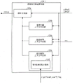
Fig. 1 is a block diagram showing a configuration of a quantized residual information decoding unit provided in a moving picture decoding device according to an embodiment of the present invention.
Fig. 2 is a diagram showing a data structure of encoded data generated by a moving image encoding device according to an embodiment of the present invention and decoded by a moving image decoding device, and (a) to (d) are diagrams showing a picture layer, a slice layer, a tree layer, and a CU layer, respectively.
Fig. 3 is a diagram showing a pattern of a PU partition type. (a) Each of (h) to (h) shows a partition shape in the case where the PU partition type is 2N × N, 2N × nU, 2N × nD, 2N × N, 2N × nU, and 2N × nD.
Fig. 4 is a diagram showing a division method of a square node quadtree into squares or non-squares. (a) The following description shows the division of a square, (b) the division of a horizontally long rectangle, (c) the division of a vertically long rectangle, (d) the division of a horizontally long node, and (e) the division of a square of a horizontally long node, (f) the division of a vertically long node, and (g) the division of a square of a vertically long node.
Fig. 5 is a diagram showing each syntax included in quantization residual information of encoded data according to the embodiment.
Fig. 6 is a diagram for explaining the operation of the quantized residual information decoding unit according to the embodiment, where (a) shows the processing procedure in forward scanning, (b) shows the processing procedure in reverse scanning, (c) shows transform coefficients other than 0 in the processing frequency region, (d) shows values of syntax significant _ coeff _ flag in the target frequency region, (e) shows values obtained by decoding syntaxes coeff _ abs _ level _ header 1_ flag, coeff _ abs _ level _ header 2_ flag, and coeff _ abs _ level _ minus3 in the target frequency region, (f) shows values of syntax coeff _ sign _ flag in the target frequency region, and (g) shows an example of grouping in a frequency region composed of 8 × 8 frequency components.
Fig. 7 is a block diagram showing the configuration of the moving picture decoding apparatus according to the embodiment.
Fig. 8 is a block diagram showing a configuration of a variable-length code decoding unit included in the moving image decoding device according to the embodiment.
Fig. 9 is a diagram showing a frequency domain divided into 4 partial domains by the frequency classification unit according to the embodiment.
Fig. 10 is a diagram showing the operation of the peripheral reference context derivation unit according to the embodiment, where (a) shows the target frequency component x in the reverse scan order and the reference frequency components c1 to c5 included in the reference region set around the position of the target frequency component x, (b) shows the target frequency component x in the forward scan order and the reference frequency components c1 to c5 included in the reference region set around the position of the target frequency component x, and (c) shows the case where the reference region extends from the target frequency region.
Fig. 11(a) is a diagram showing a frequency domain divided into 3 partial regions by the frequency classifying unit according to the embodiment, and fig. 11(b) is a diagram showing a frequency domain divided into 2 partial regions by the frequency classifying unit according to the embodiment.
Fig. 12 is a block diagram showing a configuration example 2 of the coefficient presence flag decoding unit according to the embodiment.
Fig. 13 is a diagram for explaining a configuration example 2 of the coefficient presence flag decoding unit according to the embodiment, where (a) shows a scan column Lx and a scan column Lx +1, and (b) shows a portion in which last _ cntx and last _ cnty are counted in the scan column Lx and the scan column Lx +1, respectively.
Fig. 14 is a block diagram showing a configuration example 3 of the coefficient presence flag decoding unit according to the embodiment.
Fig. 15 is a diagram showing reference regions to be referred to by the peripheral reference context derivation unit in the 3 rd configuration example of the coefficient presence flag decoding unit according to the embodiment, (a) to (b) illustrate reference regions with reference number 4, (c) to (f) illustrate reference regions with reference number 3, (g) to (h) illustrate reference regions with reference number 2, and (i) shows another example of reference regions with reference number 3.
Fig. 16 is a diagram for explaining a configuration example 3 of the coefficient presence flag decoding unit according to the embodiment, and shows a case where partial regions R2 and R3 share a partial context among partial regions R0 to R3 constituting a target frequency region.
Fig. 17 is a block diagram showing a 4 th configuration example of the coefficient presence flag decoding unit according to the embodiment.
Fig. 18 is a diagram for explaining a 4 th configuration example of the coefficient presence flag decoding unit according to the embodiment, and shows a case where partial contexts are shared by partial regions R2 and R3 among R0 to R4 constituting a target frequency region.
Fig. 19 is a block diagram showing a configuration example 5 of the coefficient presence flag decoding unit according to the embodiment.
Fig. 20 is a diagram for explaining a configuration example 5 of the coefficient presence flag decoding unit according to the embodiment, and shows a scan line Lx, a scan line Lx +1, and a scan line Lx + 2.
Fig. 21 is a diagram for explaining a 5 th configuration example of the coefficient presence flag decoding unit according to the embodiment, and (a) to (c) illustrate reference regions with reference number 2.
Fig. 22 is a block diagram showing a configuration example 6 of the coefficient presence flag decoding unit according to the embodiment.
Fig. 23 is a diagram for explaining another configuration example of the quantized residual information decoding unit according to the embodiment, and shows a low-frequency side partial region R0 'and a high-frequency side partial region R1' obtained by dividing a frequency region.
Fig. 24 is a diagram for explaining another configuration example of the quantized residual information decoding unit according to the embodiment, in which (a) shows each value of a hierarchy and a restriction setting corresponding to the value, and (b) shows each value of a hierarchy and a setting of a threshold corresponding to the value.
Fig. 25 is a diagram for explaining another configuration example of the quantized residual information decoding unit according to the embodiment, where (a) shows values of context indices derived by the coefficient presence/absence flag decoding unit according to the comparative example, (b) shows values of context indices ctxIdx derived by the coefficient presence/absence flag decoding unit according to the configuration example, (c) shows an example of ctxIdxH derived by the coefficient presence/absence flag decoding unit according to the configuration example, and (d) shows an example of ctxIdxV derived by the coefficient presence/absence flag decoding unit according to the configuration example.
Fig. 26 is a block diagram showing the configuration of the moving image coding device according to the embodiment.
Fig. 27 is a block diagram showing a configuration of a variable-length code encoding unit included in the moving image encoding device according to the embodiment.
Fig. 28 is a block diagram showing a configuration of a quantization residual information encoding unit included in the variable length code encoding unit according to the embodiment.
Fig. 29 is a diagram showing a configuration of a transmitting apparatus on which the moving image encoding apparatus is mounted and a receiving apparatus on which the moving image decoding apparatus is mounted. (a) A transmitting device equipped with a moving image encoding device is shown, and a receiving device equipped with a moving image decoding device is shown.
Fig. 30 is a diagram showing a configuration of a recording apparatus on which the moving image encoding apparatus is mounted and a playback apparatus on which the moving image decoding apparatus is mounted. (a) A recording apparatus equipped with a moving image encoding apparatus is shown, and (b) a playback apparatus equipped with a moving image decoding apparatus is shown.
Fig. 31 is a block diagram showing a configuration example 7 of the coefficient presence flag decoding unit according to the embodiment.
Fig. 32 is a diagram for explaining configuration examples 7 to 9 of the coefficient presence flag decoding unit according to the embodiment, and shows scanning in units of sub-blocks.
Fig. 33 is a flowchart showing an example of the operation flow in the 7 th to 9 th configuration examples of the coefficient presence flag decoding unit according to the embodiment.
Fig. 34 is a flowchart showing another example of the operation flow in the 7 th to 9 th configuration examples of the coefficient presence flag decoding unit according to the embodiment.
Fig. 35 is a diagram showing an example of a frequency domain divided into partial domains R0, R1, and R2 by the classification processing performed by the frequency classification unit included in the 7 th configuration example of the coefficient presence flag decoding unit according to the embodiment.
Fig. 36 is a diagram for explaining configuration examples 7 to 9 of the coefficient presence flag decoding unit according to the embodiment, and shows reference frequency components c1 to c5 included in a reference region set around the position of the target frequency component x.
Fig. 37 is a block diagram showing an 8 th configuration example of the coefficient presence flag decoding unit according to the embodiment.
Fig. 38 is a diagram showing an example of a frequency domain into which partial regions R0, R1, R2, and R3 are divided by the classification processing performed by the frequency classification unit included in the 8 th configuration example of the coefficient presence flag decoding unit according to the embodiment.
Fig. 39 is a diagram showing another example of a frequency domain divided into partial domains R0, R1, R2, and R3 by the classification processing performed by the frequency classification unit included in the 8 th configuration example of the coefficient presence flag decoding unit according to the embodiment.
Fig. 40 is a block diagram showing a 9 th configuration example of the coefficient presence flag decoding unit according to the embodiment.
Fig. 41 is a diagram showing an example of a frequency domain into which partial regions R0, R1, R2, R3, and R4 are divided by the classification processing performed by the frequency classification unit included in the 9 th configuration example of the coefficient presence flag decoding unit according to the embodiment.
Fig. 42 is a diagram showing another example of a frequency domain divided into partial domains R0, R1, R2, R3, and R4 by the classification processing performed by the frequency classification unit included in the 9 th configuration example of the coefficient presence flag decoding unit according to the embodiment.
Fig. 43 is a flowchart showing an operation flow executed by the 7 th to 9 th configuration examples of the coefficient presence flag encoding unit according to the embodiment.
Fig. 44 is a block diagram showing a configuration example 7 of the coefficient presence flag encoding unit according to the embodiment.
Fig. 45 is a block diagram showing an 8 th configuration example of the coefficient presence flag encoding unit according to the embodiment.
Fig. 46 is a block diagram showing a 9 th configuration example of the coefficient presence flag encoding unit according to the embodiment.
Fig. 47 is a diagram for explaining the presence or absence of a flag for a sub-block coefficient according to the embodiment, where (a) shows an example of each value of a quantized residual coefficient for a total of 256 frequency components included in a 16 × 16 transform block, (b) shows an example of a sub-block number for identifying each sub-block obtained by dividing the 16 × 16 transform block into 4 × 4 sub-blocks, and (c) shows an example of the presence or absence of a flag for a sub-block coefficient of each sub-block when the quantized residual coefficient is as shown in (a).
Fig. 48 is a diagram for explaining the classification processing performed by the frequency classification unit included in the coefficient presence/absence flag decoding unit according to the embodiment, where (a) shows a partial region division suitable for application when decoding a transform coefficient related to a luminance value, and (b) shows a partial region division suitable for application when decoding a transform coefficient related to a color difference.
Fig. 49 is a pseudo code for explaining a context index derivation process according to another configuration example of configuration example 3 of the coefficient presence flag decoding unit according to the embodiment, and is a pseudo code for deriving a context index assigned to each of the frequency regions included in the partial regions R0 to R3 shown in fig. 48 (a).
Fig. 50 is a diagram for explaining the context index derivation process by the coefficient presence flag decoding unit according to the embodiment, and is pseudo code showing the derivation process of deriving the context index assigned to the frequency region included in each of the partial regions R0 to R3 shown in fig. 48 (b).
Fig. 51 is a diagram for explaining another configuration example of the 3 rd configuration example of the coefficient presence flag decoding unit according to the embodiment, and shows reference frequency components c1, c2, and c5 included in a reference region set around the position of the target frequency component x.
Fig. 52 is a pseudo code for explaining a context index derivation process according to another configuration example of the 8 th configuration example of the coefficient presence flag decoding unit according to the embodiment, and is a pseudo code for deriving a context index assigned to each of the frequency regions included in the partial regions R0 to R3 shown in fig. 48 (a).
Fig. 53 is a diagram for explaining a context index derivation process according to another configuration example of the 8 th configuration example of the coefficient presence flag decoding unit according to the embodiment, and is pseudo code showing a derivation process for deriving a context index assigned to each of the frequency regions included in the partial regions R0 to R3 shown in fig. 48 (b).
Fig. 54 is a pseudo code for explaining a context index derivation process according to another configuration example of the 8 th configuration example of the coefficient presence flag decoding unit according to the embodiment, and is a pseudo code for deriving a context index assigned to each of the frequency regions included in the partial regions R0 to R3 shown in fig. 48 (a).
Fig. 55 is a diagram for explaining a context index derivation process according to another configuration example of the 8 th configuration example of the coefficient presence flag decoding unit according to the embodiment, and is pseudo code showing a derivation process for deriving a context index assigned to each of the frequency regions included in the partial regions R0 to R3 shown in fig. 48 (b).
Fig. 56 is a diagram for explaining a context index derivation process according to another configuration example of the 8 th configuration example of the coefficient presence flag decoding unit according to the embodiment, and is pseudo code showing a derivation process for deriving context indexes assigned to frequency regions included in each of the partial regions R0 to R3 shown in fig. 48(a) to (b).
Fig. 57 is a diagram for explaining the context index derivation process of the configuration example in which the context update delay removal is considered based on the 8 th configuration example of the coefficient presence flag decoding unit according to the embodiment.
Fig. 58 is a diagram for explaining the context index derivation process of the configuration example in which the context update delay removal is considered based on the 8 th configuration example of the coefficient presence flag decoding unit according to the embodiment.
Fig. 59 is a pseudo code for explaining a context index derivation process of a configuration example in which context update delay removal is considered based on the 8 th configuration example of the coefficient presence flag decoding unit according to the embodiment, and is a pseudo code for deriving a context index assigned to each of the frequency regions included in the partial regions R0 to R3 shown in fig. 48(a) to (b).
Fig. 60 is a pseudo code for explaining a context index derivation process of a configuration example in which context update delay removal is considered based on the 8 th configuration example of the coefficient presence flag decoding unit according to the embodiment, and is a pseudo code for deriving a context index assigned to each of the frequency regions included in the partial regions R0 to R3 shown in fig. 48(a) to (b).
Fig. 61 is a block diagram showing the configuration of a quantized residual information decoding unit provided in the moving picture decoding apparatus 3 according to the embodiment of the present invention.
Fig. 62 is a diagram showing the first half of a syntax table showing syntax included in quantization residual information of encoded data according to the related art.
Fig. 63 is a diagram showing the second half of a syntax table showing syntax included in quantization residual information of encoded data according to the related art.
Fig. 64 is a diagram showing the first half of a syntax table showing syntax included in quantization residual information of encoded data according to the embodiment.
Fig. 65 is a diagram showing a general configuration of the second half of a syntax table showing syntax included in quantization residual information of encoded data according to the embodiment.
Fig. 66 is a diagram showing a simplified structure 1 in the second half of a syntax table showing syntax included in quantization residual information of encoded data according to the embodiment.
Fig. 67 is a diagram showing a simplified configuration 2 of the second half of a syntax table showing syntax included in quantization residual information of encoded data according to the embodiment.
Fig. 68 is a diagram showing a simplified configuration of the second half of a syntax table showing syntax included in quantization residual information of encoded data according to the embodiment, which is 3 rd.
Fig. 69 is a diagram showing a 4 th simplified configuration of the second half of a syntax table showing syntax included in quantization residual information of encoded data according to the embodiment.
Fig. 70 is a diagram showing a 5 th simplified configuration of the second half of a syntax table showing syntax included in quantization residual information of encoded data according to the embodiment.
Fig. 71 is a diagram showing a syntax structure indicating a syntax coeff _ abs _ minus included in quantization residual information of encoded data according to the embodiment.
Fig. 72 is a flowchart showing the process of deriving the simplified processing flag campac _ lowcomp _ flag according to the embodiment.
Fig. 73 is a flowchart showing the detailed process of the derivation process of the simplified process flag campac _ lowcomp _ flag according to the embodiment.
Fig. 74 is a block diagram showing the configuration of a quantized residual information encoding unit provided in the moving image encoding device 3 according to the embodiment of the present invention.
Fig. 75 is a block diagram showing a configuration of the coefficient presence flag encoding unit Y224 according to the embodiment.
Detailed Description
An embodiment of a decoding device and an encoding device according to the present invention will be described below with reference to the drawings. The decoding device according to the present embodiment is used for decoding a moving image from encoded data. Therefore, this will be referred to as "moving picture decoding apparatus" hereinafter. The encoding device according to the present embodiment generates encoded data by encoding a moving image. Therefore, this will be referred to as "moving picture coding apparatus" hereinafter.
However, the scope of application of the present invention is not limited thereto. That is, as will be apparent from the following description, the features of the present invention are also true when a plurality of frames are not assumed. That is, the present invention is applicable to all decoding apparatuses and all encoding apparatuses regardless of whether a moving image or a still image is targeted.
(constitution of coded data # 1)
A configuration example of encoded data # 1 generated by the moving picture encoding device 2 and decoded by the moving picture decoding device 1 will be described with reference to fig. 2. The encoded data # 1 illustratively includes a sequence and a plurality of pictures constituting the sequence.
In the sequence layer, a set of data to be referred to by the moving image decoding apparatus 1 for decoding a sequence to be processed is defined. The sequence layer comprises a sequence parameter set SPS, a picture parameter set PPS and a picture PICT.
The structure of the hierarchy below the picture layer in the encoded data # 1 is shown in fig. 2. Fig. 2 (a) to (d) are diagrams each showing a picture layer defining a picture PICT, a slice layer defining a slice S, a Tree layer defining a Tree block (Tree block) TBLK, and a CU layer defining a Coding Unit (CU) included in the Tree block TBLK.
(Picture layer)
In the picture layer, a set of data to be referred to by the moving picture decoding apparatus 1 for decoding a picture PICT to be processed (hereinafter also referred to as a target picture) is defined. The picture PICT includes a picture header PH and a slice S as shown in FIG. 2 (a)1~SNS(NS is the total number of slices contained in the picture PICT).
In addition, in the following, there is no need to distinguish the slice S1~SNSIn the case of each slice of (2), the subscript of the reference numeral may be omitted. The same applies to other data included in encoded data # 1 described below and denoted by a subscript.
The picture header PH includes a group of encoding parameters to be referred to by the moving picture decoding apparatus 1 in order to determine a decoding method of a target picture. For example, coding mode information (entry _ coding _ mode _ flag) indicating a variable length coding mode used by the moving picture coding apparatus 2 at the time of coding is an example of a coding parameter included in the picture header PH.
When the entropy _ Coding _ mode _ flag is 0, the picture PICT is coded by CAVLC (Context-based Adaptive Variable Length Coding). In addition, when the entry _ Coding _ mode _ flag is 1, the picture PICT is coded by CABAC (Context-based Adaptive Binary Arithmetic Coding).
(slice layer)
In the slice layer, a set of data to be referred to by the moving image decoding apparatus 1 for decoding a slice S to be processed (also referred to as a target slice) is defined. The slice S includes a slice header SH and a tree block TBLK as shown in fig. 2 (b)1~TBLKNC(NC is the total number of treeblocks contained in slice S).
The slice header SH contains a group of encoding parameters to be referred to by the moving picture decoding apparatus 1 in order to determine a decoding method of a target slice. The slice type specification information (slice _ type) specifying the slice type is an example of the coding parameter included in the slice header SH.
The slice types that can be specified by the slice type specifying information include (1) an I slice that uses only intra prediction at the time of encoding, (2) a P slice that uses mono prediction or intra prediction at the time of encoding, and (3) a B slice that uses mono prediction, bi prediction, or intra prediction at the time of encoding.
The slice header SH includes a filter parameter FP to be referred to by a loop filter provided in the moving image decoding apparatus 1. The filter parameters FP include filter coefficient groups. The filter coefficient group includes: (1) tap number specifying information for specifying the number of taps of a filter, (2) filter coefficient a 0~aNT-1(NT is the total number of filter coefficients included in the filter coefficient group), and (3) an offset o.
(layer of Tree block)
In the tree block layer, a set of data to be referred to by the moving picture decoding apparatus 1 for decoding a tree block TBLK to be processed (hereinafter also referred to as a target tree block) is defined.
The tree block TBLK includes a tree block header TBLKH and coding unit information CU1~CUNL(NL is the total number of coding unit information included in the tree block TBLK). Here, first, the relationship between the tree block TBLK and the coding unit information CU will be described below.
The tree block TBLK is divided into units for determining block sizes for respective processes of intra prediction, inter prediction, and transformation.
The above-described units of the tree block TBLK are divided by recursive quadtree division. A tree structure obtained by dividing the recursive quadtree is hereinafter referred to as a coding tree (coding tree).
Hereinafter, a unit corresponding to a leaf (leaf) which is a node at the end of the coding tree is referred to as a coding node (coding node). Since the coding node is a basic unit of coding processing, the coding node is also referred to as a Coding Unit (CU) hereinafter.
I.e. coding unit information CU1~CUNLThe information is information corresponding to each coding node (coding unit) obtained by recursively quadtree-dividing the tree block TBLK.
In addition, the root (root) of the code tree is associated with the tree block TBLK. In other words, the tree block TBLK corresponds to the uppermost node of a quadtree-partitioned tree structure including a plurality of coding nodes recursively.
In addition, the size of each coding node is half of the size of the vertical and horizontal sides of the coding node to which the coding node directly belongs (i.e., the unit of the node of the upper level 1 of the coding node).
The size of each coding node is determined by the size specification information and the maximum hierarchical depth (maximum hierarchical depth) of the coding node included in the sequence parameter set SPS of the coded data # 1. For example, in the case where the size of the tree block TBLK is 64 × 64 pixels and the maximum hierarchy depth is 3, the coding nodes in the hierarchy below the tree block TBLK may take any of 4 sizes, i.e., 64 × 64 pixels, 32 × 32 pixels, 16 × 16 pixels, and 8 × 8 pixels.
(Tree block head)
The tree block header TBLKH includes encoding parameters to be referred to by the moving picture decoding apparatus 1 in order to determine a decoding method of a target tree block. Specifically, as shown in fig. 2 (c), the method includes: the quantization parameter difference Δ qp (qp _ delta) specifies the quantization parameter difference Δ qp of the quantization step size and the tree block division information SP _ TBLK specifying the division pattern of the target tree block into CUs.
The tree block division information SP _ TBLK is information indicating a code tree for dividing a tree block, and specifically, is information for specifying the shape and size of each CU included in a target tree block and specifying the position within the target tree block.
The tree block division information SP _ TBLK may not explicitly include the shape and size of the CU. For example, the tree block division information SP _ TBLK may be a set of flags (split _ coding _ unit _ flag) indicating whether the whole of the object tree block or a partial region of the tree block is quartered. In this case, the shape and size of each CU are determined by using the shape and size of the tree block.
The quantization parameter difference Δ qp is a difference qp-qp 'between the quantization parameter qp in the target tree block and the quantization parameter qp' in the tree block coded immediately before the target tree block.
(layer of CU)
In the CU layer, a set of data to be referred to by the moving picture decoding apparatus 1 for decoding a CU to be processed (hereinafter, also referred to as a target CU) is defined.
Here, before the description of the specific content of the data included in the coding unit information CU, the tree structure of the data included in the CU will be described. The coding node becomes a node of a root of a Prediction Tree (PT) and a Transform Tree (TT). The prediction tree and the transform tree are explained as follows.
In the prediction tree, a coding node is divided into 1 or more prediction blocks, and the position and size of each prediction block are specified. In other expressions, the prediction block is 1 or more non-overlapping regions constituting the coding node. The prediction tree includes 1 or more prediction blocks obtained by the above-described division.
The prediction process is performed for each of the prediction blocks. Hereinafter, a prediction block, which is a unit of prediction, is also referred to as a Prediction Unit (PU).
The types of partitions in the prediction tree are roughly two types, i.e., intra prediction and inter prediction.
In the case of intra prediction, the partitioning method has 2N × 2N (same size as the coding node) and N × N.
In the case of inter prediction, the division method includes 2N × 2N (the same size as the coding node), 2N × N, N × 2N, and N × N.
In the transform tree, the coding node is divided into 1 or more transform blocks, and the position and size of each transform block are defined. In other expressions, a transform block is 1 or more non-overlapping regions that constitute a coding node. The transform tree includes 1 or more transform blocks obtained by the above-described division.
The transform processing is performed for each of the transform blocks. Hereinafter, a transform block, which is a unit of transform, is also referred to as a Transform Unit (TU).
(data Structure of coding Unit information)
Next, specific contents of data included in the coding unit information CU will be described with reference to (d) of fig. 2. As shown in fig. 2 (d), the coding unit information CU specifically includes: SKIP mode flag SKIP, CU prediction type information Pred _ type, PT information PTI, and TT information TTI.
[ skip mark ]
The SKIP flag SKIP is a flag indicating whether or not the SKIP mode is applied to the target CU, and when the value of the SKIP flag SKIP is 1, that is, when the SKIP mode is applied to the target CU, the PT information PTI in the coding unit information CU is omitted. Furthermore, the SKIP flag SKIP is omitted in the I slice.
[ CU prediction type information ]
The CU prediction type information Pred _ type includes CU prediction mode information PredMode and PU partition type information PartMode. CU prediction type information is sometimes also referred to as prediction type information only.
The CU prediction mode information PredMode is used to specify which of intra prediction (intra CU) and inter prediction (inter CU) is used as a prediction image generation method for each PU included in the target CU. In the following, the types of skip, intra prediction, and inter prediction in the target CU are referred to as CU prediction modes.
The PU partition type information PartMode is used to specify a PU partition type, which is a pattern of partitioning a target Coding Unit (CU) into PUs. Hereinafter, the operation of dividing the target Coding Unit (CU) into PUs according to the PU division type is referred to as PU division.
The PU partition type information PartMode may be, for example, an index indicating the type of the PU partition pattern, or may be an index indicating the shape and size of each PU included in the object prediction tree and the position of each PU in the object prediction tree.
In addition, the selectable PU partition types differ according to CU prediction modes and CU sizes. Further, the selectable PU partition types are different in each case of inter prediction and intra prediction. In addition, details regarding the PU partition type are described later.
In addition, in the case of not an I slice, the value of the PU partition type information PartMode and the value of the PU partition type information PartMode may be determined by an index (CU _ split _ pred _ part _ mode) specifying a combination of methods of partitioning (partition) of a treeblock, a prediction method, and partitioning (split) of a CU.
[ PT information ]
The PT information PTI is information related to PTs included in the target CU. In other words, the PT information PTI is a set of information respectively related to 1 or more PUs included in the PT. As described above, the generation of the prediction image is performed in units of PU, and therefore the PT information PTI is referred to when the prediction image is generated by the moving image decoding apparatus 1. The PT information PTI includes PU information PUI including prediction information and the like in each PU, as shown in FIG. 2 (d) 1~PUINP(NP is the total number of PUs contained in the target PT).
The prediction information PUI includes an Intra prediction parameter PP _ Intra or an Inter prediction parameter PP _ Inter according to which prediction method is specified by the prediction type information Pred _ mode. Hereinafter, a PU to which intra prediction is applied is also referred to as an intra PU, and a PU to which inter prediction is applied is also referred to as an inter PU.
The Inter prediction parameter PP _ Inter includes an encoding parameter to be referred to by the moving image decoding device 1 when generating an Inter prediction image by Inter prediction.
Examples of the Inter prediction parameter PP _ Inter include a merge flag (merge _ flag), a merge index (merge _ idx), an estimated motion vector index (mvp _ idx), a reference picture index (ref _ idx), an Inter prediction flag (Inter _ pred _ flag), and a motion vector residual (mvd).
The Intra prediction parameter PP _ Intra includes an encoding parameter to be referred to by the moving picture decoding apparatus 1 when generating an Intra prediction image by Intra prediction.
As the Intra prediction parameter PP _ Intra, for example, an estimated prediction mode flag, an estimated prediction mode index, and a residual prediction mode index can be cited.
The intra prediction parameter may also include a PCM mode flag indicating whether or not the PCM mode is used. When the PCM mode flag indicates a PCM mode to be used in the case where the PCM mode flag is coded, each of the prediction processing (intra frame), the transform processing, and the entropy coding is omitted.
[ TT information ]
TT information TTI is information related to TT included in a CU. In other words, the TT information TTI is a set of information related to each of 1 or more TUs included in the TT, and is referred to when residual data is decoded by the moving image decoding apparatus 1. Hereinafter, TU may be referred to as a block.
TT information TTI, as shown in fig. 2 (d), includes TT division information SP _ TU specifying a division pattern for dividing a target CU into transform blocks, and TU information TUI1~TUINT(NT is the total number of blocks contained by the subject CU).
The TT division information SP _ TU is specifically information for determining the shape, size, and position of each TU included in the target CU. For example, the TT division information SP _ TU can be realized by information (split _ transform _ flag) indicating whether or not to divide the target node, and information (trafoDepth) indicating the depth of the division.
For example, when the size of a CU is 64 × 64, each TU obtained by division may have a size of 32 × 32 pixels to 4 × 4 pixels.
TU information TUI1~TUINTIs individual information related to 1 or more TUs included in the TT, respectively. For example, the TU information TUI contains a quantized prediction residual (also referred to as a quantized residual).
Each quantized prediction residual is generated by the moving picture coding apparatus 2 by performing the following processes 1 to 3 on a target block which is a block to be processed.
Treatment 1: performing frequency Transform (for example, DCT Transform) on a prediction residual obtained by subtracting a predicted image from an encoding target image;
and (3) treatment 2: quantizing the transform coefficients obtained by the processing 1;
and (3) treatment: variable length coding is performed on the transform coefficients quantized by the processing 2;
the quantization parameter QP indicates the size of a quantization step QP used when the moving picture coding apparatus 2 quantizes the transform coefficient (QP 2)qp/6)。
(PU partition type)
When the size of the target CU is 2N × 2N pixels, the PU partition type has the following total of 8 patterns. That is, 4 symmetrical divisions (symmetry divisions) of 2N × 2N pixels, 2N × N pixels, N × 2N pixels, and N × N pixels, and 4 asymmetrical divisions (asymmetric divisions) of 2N × nU pixels, 2N × nD pixels, nL × 2N pixels, and nR × 2N pixels. Where N is 2m (m is an arbitrary integer of 1 or more). Hereinafter, a region obtained by dividing a symmetric CU is also referred to as a partition.
Fig. 3 (a) to (h) specifically show the positions of the boundaries of PU partitions in a CU for each partition type.
Fig. 3 (a) shows a 2N × 2N PU partition type without CU partition. Fig. 3 (b), (c), and (d) show the shapes of the partitions when the PU partition types are 2N × N, 2N × nU, and 2N × nD, respectively. Fig. 3 (e), (f), and (g) show the shapes of the partitions when the PU partition types are N × 2N, nL × 2N and nR × 2N, respectively. Fig. 3 (h) shows the shape of a partition when the PU partition type is N × N.
The PU partition type in fig. 3 (a) and (h) is also referred to as square partition based on the shape of the partition. The PU division types in fig. 3 (b) to (g) are also referred to as non-square division.
In fig. 3 (a) to (h), the numbers given to the respective regions indicate the identification numbers of the regions, and the regions are processed in the order of the identification numbers. That is, the identification number indicates the scanning order of the area.
[ partition type in the case of inter prediction ]
In the inter PU, 7 types other than N × N ((h) of fig. 3) among the above 8 partition types are defined. The 4 asymmetric divisions may be referred to as amp (asymmetric Motion partition).
The specific value of N is defined according to the size of the CU to which the PU belongs, and the specific values of nU, nD, nL, and nR are determined according to the value of N. For example, a 128 × 128-pixel inter CU can be divided into 128 × 128 pixels, 128 × 64 pixels, 64 × 128 pixels, 64 × 64 pixels, 128 × 32 pixels, 128 × 96 pixels, 32 × 128 pixels, and 96 × 128-pixel inter PUs.
[ partition type in the case of Intra prediction ]
In the intra PU, the following 2 kinds of partition patterns are defined. That is, a division pattern 2N × 2N in which the target CU is not divided, that is, the target CU itself is treated as 1 PU; the target CU is symmetrically divided into patterns N × N of 4 PUs.
Therefore, in the intra PU, the example shown in fig. 3 may be divided into the patterns (a) and (h).
For example, a 128 × 128-pixel intra CU can be divided into 128 × 128 pixels and 64 × 64-pixel intra PUs.
(TU division type)
Next, the TU partition type is described with reference to fig. 4. The pattern of TU partition is determined by the size of the CU, the depth of the partition (trafoDepth), and the PU partition type of the object PU.
The pattern of TU division includes square quadtree division and non-square quadtree division.
Fig. 4 (a) to (c) show a division method of dividing a square node quadtree into squares or non-squares. More specifically, fig. 4 (a) shows a division method of dividing a square node quadtree into squares. In addition, fig. (b) shows a division method of dividing a square node quadtree into horizontally long rectangles. In addition, fig. (c) shows a division method of dividing a square node quadtree into vertically long rectangles.
In addition, (d) to (g) of fig. 4 show a division method of dividing a non-square node quadtree into a square or a non-square. More specifically, fig. 4 (d) shows a division method of dividing a node quadtree of a horizontally long rectangle into horizontally long rectangles. In addition, fig. (e) shows a division method of dividing a horizontally long rectangular node quadtree into squares. In addition, (f) of the figure shows a division method of dividing a node quadtree of a vertically long rectangle into vertically long rectangles. In addition, (g) of the figure shows a division method of dividing a vertically long rectangular node quadtree into squares.
(constitution of quantization residual information QD)
Fig. 5 is a table showing syntax included in quantization residual information QD (denoted as residual _ coding _ cabac ()' in fig. 5).
As shown in fig. 5, the quantization residual information QD includes syntax last _ significant _ coeff _ x, last _ significant _ coeff _ y, significant _ coeff _ flag, coeff _ abs _ level _ coarse _ flag, coeff _ abs _ level _ header 2_ flag, coeff _ sign _ flag, coeff _ abs _ level _ minus 3.
Each syntax included in the quantization residual information QD is coded by Context-Adaptive Binary arithmetic coding (CABAC).
Hereinafter, the decoding process of each syntax will be described with reference to fig. 5 to 6, taking as an example a case where the block size is 8 × 8 pixels. In FIGS. 6(a) to (g), the horizontal axis represents the horizontal frequency xC (0. ltoreq. xC. ltoreq.7), and the vertical axis represents the vertical frequency yC (0. ltoreq. yC. ltoreq.7). In the following description, a partial region specified by a horizontal direction frequency xC and a vertical direction frequency yC among partial regions included in a frequency region is also referred to as a frequency component (xC, yC). In addition, the transform coefficient for the frequency component (xC, yC) is also denoted as Coeff (xC, yC). The transform coefficient Coeff (0, 0) represents a DC component, and the other transform coefficients represent components other than the DC component. In the present specification, (xC, yC) may be represented as (u, v), or (uiPosX, uiPosY), or the like.
Fig. 6(a) to (b) are diagrams showing examples of the scanning procedure in the frequency region FR configured by 8 × 8 frequency components.
In the example shown in fig. 6 a, scanning is performed in order from the low frequency side (upper left in fig. 6 a) to the high frequency side (lower right in fig. 6 a). In the example shown in fig. 6(a), scanning is performed along the arrow shown in the frequency region FR. The scanning sequence shown in fig. 6(a) may be referred to as a forward scan.
On the other hand, in the example shown in fig. 6(b), scanning is performed sequentially from the high frequency side (lower right in fig. 6 (b)) to the low frequency side (upper left in fig. 6 (b)). In the example shown in fig. 6(b), scanning is performed along the arrow shown in the frequency region FR. The scanning order shown in fig. 6(b) may be referred to as a reverse scan.
Fig. 6 c is a diagram illustrating a transform coefficient other than 0 (non-0 transform coefficient) in a frequency region constituted by 8 × 8 frequency components.
The syntax last _ significant _ coeff _ x and last _ significant _ coeff _ y are the syntax representing the position of the last non-0 transform coefficient along the forward scan direction. In the case of the example shown in fig. 6(c), last _ significant _ coeff _ x is 6, and last _ significant _ coeff _ y is 0.
The syntax significant _ coeff _ flag is syntax indicating the presence or absence of a non-0 transform coefficient for each frequency component in the reverse scan direction starting from the non-0 transform coefficient. Fig. 6(d) shows the values of syntax significant _ coeff _ flag in the case where the transform coefficient of the decoding target is as shown in fig. 6 (c). As shown in fig. 6(d), the syntax significant _ coeff _ flag is a flag indicating that 0 is used for a transform coefficient of 0 and 1 is used for a transform coefficient of not 0 for each of xC and yC. The syntax significant _ coeff _ flag is also referred to as a transform coefficient presence flag.
The syntax coeff _ abs _ level _ coarse _ flag is a flag indicating whether or not the absolute value of the transform coefficient exceeds 1, and is encoded for a frequency component of which the value of the syntax significant _ coeff _ flag is 1. When the absolute value of the transform coefficient exceeds 1, the value of coeff _ abs _ level _ granularity _ flag is 1, otherwise the value of coeff _ abs _ level _ granularity 1_ flag is 0.
The syntax coeff _ abs _ level _ header 2_ flag is a flag indicating whether the absolute value of a transform coefficient exceeds 2, and is encoded when the value of coeff _ abs _ level _ header 1_ flag is 1. When the absolute value of the transform coefficient exceeds 2, the value of coeff _ abs _ level _ header 2_ flag is 1, otherwise the value of coeff _ abs _ level _ header 2_ flag is 0.
The syntax coeff _ abs _ level _ minus3 is syntax for specifying the absolute value of a transform coefficient when the absolute value of the transform coefficient is 3 or more, and is encoded when the value of coeff _ abs _ level _ header 2_ flag is 1. The value of the syntax coeff _ abs _ level _ minus3 is a value obtained by subtracting 3 from the absolute value of the transform coefficient. For example, coeff _ abs _ level _ minus3 being 1 indicates that the absolute value of the transform coefficient is 4.
Fig. 6(e) shows absolute values of transform coefficients obtained by decoding the syntax coeff _ abs _ level _ granularity _ flag, coeff _ abs _ level _ granularity 2_ flag, and coeff _ abs _ level _ minus 3.
The syntax coeff _ sign _ flag is a flag indicating the sign (positive or negative) of the transform coefficient, and is encoded for a frequency component of which the value of syntax significant _ coeff _ flag is 1.
Fig. 6(f) shows a syntax coeff _ sign _ flag in the case where the transform coefficient to be decoded is as shown in fig. 6 (c). As shown in fig. 6(f), the syntax coeff _ sign _ flag is a flag that takes 1 if the transform coefficient is positive and 0 if the transform coefficient is negative.
The variable-length code decoding unit 11 included in the moving picture decoding apparatus 1 can generate a transform coefficient Coeff (xC, yC) for each frequency component by decoding the syntax last _ significant _ Coeff _ x, last _ significant _ Coeff _ y, significant _ Coeff _ flag, Coeff _ abs _ level _ header 1_ flag, Coeff _ abs _ level _ header 2_ flag, Coeff _ sign _ flag, and Coeff _ abs _ level _ minus 3.
A set of non-0 transform coefficients in a specific region (for example, TU) may be referred to as a significant map.
In addition, decoding of the syntax coeff _ abs _ level _ header 1_ flag, coeff _ abs _ level _ header 2_ flag, coeff _ sign _ flag, and coeff _ abs _ level _ minus3 is performed for each group after dividing each frequency component in the frequency region into 1 or more groups. Fig. 6(g) shows an example of grouping in a frequency region constituted by 8 × 8 frequency components. The details of decoding processing for various syntaxes will be described later, and the configuration of the moving picture decoding apparatus 1 will be explained next.
(moving Picture decoding apparatus 1)
The moving image decoding device 1 according to the present embodiment will be described below with reference to fig. 1 and 7 to 25. The moving image decoding apparatus 1 is a decoding apparatus in which a technique adopted in the h.264/MPEG-4AVC standard, a technique adopted in KTA software as a codec for common development in vceg (Video Coding Expert group), a technique adopted in tmuc (test Model under configuration) software, and a technique proposed in HEVC (High-Efficiency Video Coding) as a subsequent codec are installed.
Fig. 7 is a block diagram showing the configuration of the moving picture decoding apparatus 1. As shown in fig. 7, the moving image decoding device 1 includes: a variable-length code decoding unit 11, a predicted image generating unit 12, an inverse quantization and inverse transformation unit 13, an adder 14, a frame memory 15, and a loop filter 16. As shown in fig. 7, the predicted image generation unit 12 includes: a motion vector restoration unit 12a, an inter-prediction image generation unit 12b, an intra-prediction image generation unit 12c, and a prediction method determination unit 12 d. The moving picture decoding apparatus 1 is an apparatus which generates a moving picture # 2 by decoding encoded data # 1.
(variable length code decoding section 11)
Fig. 8 is a block diagram showing a main part configuration of the variable length code decoding unit 11. As shown in fig. 8, the variable-length code decoding unit 11 includes: a quantized residual information decoding unit 111, a prediction parameter decoding unit 112, a prediction type information decoding unit 113, and a filter parameter decoding unit 114.
The variable-length code decoding unit 11 decodes the prediction parameters PP for each partition from the encoded data # 1 by the prediction parameter decoding unit 112, and supplies the decoded data to the predicted image generating unit 12. Specifically, the prediction parameter decoding unit 112 decodes the Inter prediction parameter PP _ Inter including the reference picture index, the estimated motion vector index, and the motion vector residual from the encoded data # 1 for the Inter prediction partition, and supplies these parameters to the motion vector restoration unit 12 a. On the other hand, regarding the Intra prediction partition, the Intra prediction parameter PP _ Intra including the estimated prediction mode flag, the estimated prediction mode index, and the residual prediction mode index is decoded from the encoded data # 1, and these parameters are supplied to the Intra prediction image generator 12 c.
The variable-length code decoding unit 11 decodes the prediction type information Pred _ type for each partition from the coded data # 1 by the prediction type information decoding unit 113, and supplies the decoded prediction type information Pred _ type to the prediction scheme determining unit 12 d. Further, the variable-length code decoding unit 11 decodes, by the quantization residual information decoding unit 111, quantization residual information QD concerning a block and a quantization parameter difference Δ qp concerning a TU including the block from the encoded data # 1, and supplies the result to the inverse quantization and inverse transform unit 13. The variable-length code decoding unit 11 decodes the filter parameter FP from the encoded data # 1 by the filter parameter decoding unit 114, and supplies the decoded result to the loop filter 16. Note that, since a specific configuration of the quantized residual information decoding unit 111 will be described later, a description thereof will be omitted.
(prediction image generating section 12)
The predicted image generation unit 12 identifies whether each partition is an inter prediction partition to be inter predicted or an intra prediction partition to be intra predicted, based on the prediction type information Pred _ type for each partition. In the former case, the Inter-prediction image Pred _ Inter is generated and the generated Inter-prediction image Pred _ Inter is supplied to the adder 14 as the prediction image Pred, and in the latter case, the Intra-prediction image Pred _ Intra is generated and the generated Intra-prediction image Pred _ Intra is supplied to the adder 14. When the skip mode is applied to the processing target PU, the predicted image generator 12 omits decoding of other parameters belonging to the PU.
(motion vector recovery unit 12a)
The motion vector restoration unit 12a restores the motion vector mv for each inter-prediction partition from the motion vector residual for the partition and the restored motion vector mv' for the other partition. Specifically, (1) an estimated motion vector is derived from the restored motion vector mv' by an estimation method specified by the estimated motion vector index, and (2) the motion vector mv is obtained by adding the derived estimated motion vector to the motion vector residual. In addition, the restored motion vector mv' related to the other partitions can be read out from the frame memory 15. The motion vector restoring unit 12a supplies the restored motion vector mv to the inter-prediction image generating unit 12b together with the corresponding reference image index RI.
(inter-prediction image generator 12b)
The inter-prediction image generator 12b generates a motion compensation image mc for each inter-prediction partition by inter-picture prediction. Specifically, the motion-compensated picture mc is generated from the adaptively filtered decoded picture P _ ALF' specified by the reference picture index RI similarly supplied from the motion vector restoring unit 12a, using the motion vector mv supplied from the motion vector restoring unit 12 a. Here, the adaptive-filtered decoded image P _ ALF 'is an image obtained by performing filter processing by the loop filter 16 on a decoded image in which decoding of the entire frame has been completed, and the inter-predicted image generating unit 12b can read out the pixel values of the pixels constituting the adaptive-filtered decoded image P _ ALF' from the frame memory 15. The motion-compensated image mc generated by the Inter-predicted image generator 12b is supplied to the prediction method determining unit 12d as an Inter-predicted image Pred _ Inter.
(Intra-frame prediction image generator 12c)
The Intra-prediction image generator 12c generates a prediction image Pred _ Intra regarding each Intra-prediction partition. Specifically, first, a prediction mode is determined based on the Intra prediction parameter PP _ Intra supplied from the variable length code decoding unit 11, and the determined prediction mode is assigned to the target partition, for example, in the raster scan order.
Here, the determination of the prediction mode based on the Intra prediction parameter PP _ Intra may be performed as follows. (1) When an estimated prediction mode flag indicating the same prediction mode for a target partition to be processed as that for a partition adjacent to the target partition is decoded, the prediction mode assigned to the partition adjacent to the target partition is selected for the target partition. (2) On the other hand, when the estimated prediction mode flag indicates that the prediction mode for the target partition to be processed is different from the prediction modes assigned to the partitions in the vicinity of the target partition, the residual prediction mode index is decoded, and the prediction mode indicated by the residual prediction mode index is assigned to the target partition.
The Intra-prediction image generator 12c generates a prediction image Pred _ Intra from the (local) decoded image P by Intra-picture prediction according to the prediction method indicated by the prediction mode assigned to the target partition. The Intra-prediction image Pred _ Intra generated by the Intra-prediction image generator 12c is supplied to the prediction method determination unit 12 d. The Intra-prediction image generator 12c may be configured to generate a prediction image Pred _ Intra from the adaptive-filtered decoded image P _ ALF by Intra-screen prediction.
(prediction mode determining part 12d)
The prediction method determination unit 12d determines whether each partition is an inter prediction partition to be inter predicted or an intra prediction partition to be intra predicted, based on the prediction type information Pred _ type for the PU to which each partition belongs. In the former case, the Inter prediction image Pred _ Inter generated by the Inter prediction image generator 12b is supplied to the adder 14 as the prediction image Pred, and in the latter case, the Intra prediction image Pred _ Intra generated by the Intra prediction image generator 12c is supplied to the adder 14 as the prediction image Pred.
(inverse quantization and inverse transformation unit 13)
The inverse quantization and inverse transform unit 13 (1) inversely quantizes the transform coefficient Coeff decoded from the quantization residual information QD of the encoded data # 1, (2) performs inverse frequency transform such as inverse dct (discrete Cosine transform) transform on the transform coefficient Coeff _ IQ obtained by the inverse quantization, and (3) subjects the transform coefficient Coeff _ IQ to inverse frequency transformThe prediction residual D obtained by the inverse frequency transform is supplied to the adder 14. When inverse quantizing the transform coefficient Coeff decoded from the quantization residual information QD, the inverse quantization and inverse transform unit 13 derives a quantization step QP from the quantization parameter difference Δ QP supplied from the variable-length code decoding unit 11. The quantization parameter QP may be derived by adding a quantization parameter difference Δ QP to a quantization parameter QP' associated with a TU that has been previously subjected to inverse quantization and inverse frequency transform, and the quantization step QP may be determined according to the quantization step QP, for example, by QP 2 pq/6To be derived. The inverse quantization and inverse transform unit 13 generates a prediction residual D in units of TUs or blocks into which TUs are divided.
In the inverse DCT transform performed by the inverse quantization and inverse transform unit 13, for example, when the size of the target block is 8 × 8 pixels, if the position of the pixel in the target block is (i, j) (0 ≦ i ≦ 7, 0 ≦ j ≦ 7), the value of the prediction residual D at the position (i, j) is represented as D (i, j), and the transform coefficient after the inverse quantization in the frequency component (u32, v) (0 ≦ u ≦ 7, 0 ≦ v ≦ 7) is represented as Coeff _ IQ (u, v), for example, by the following equation (1).
[ mathematical formula 1]

Here, (u, v) is a variable corresponding to (xC, yC) described above. C (u) and C (v) are given as follows.

·C(u)=1 (u≠0)

·C(v)=1 (v≠0)
(adder 14)
The adder 14 adds the prediction image Pred supplied from the prediction image generation unit 12 to the prediction residual D supplied from the inverse quantization and inverse transformation unit 13 to generate a decoded image P. The generated decoded image P is stored in the frame memory 15.
(Loop Filter 16)
The loop filter 16 has the following functions: (1) a function as a Deblocking Filter (DF) for smoothing (Deblocking processing) an image around a block boundary or a partition boundary in the decoded image P; (2) the function of an Adaptive Filter (ALF) that performs Adaptive filtering processing using a Filter parameter FP for an image to which the deblocking Filter is applied.
(quantization residual information decoding unit 111)
The quantization residual information decoding unit 111 is configured to decode the quantized transform coefficient Coeff (uiPosX, uiPosY) for each frequency component (uiPosX, uiPosY) from the quantization residual information QD included in the encoded data # 1. Here, uiPosX and uiPosY are indexes indicating the positions of the respective frequency components in the frequency domain, and are indexes corresponding to the horizontal direction frequency u and the vertical direction frequency v described above, respectively. Various syntaxes included in the quantization residual information QD are coded by Context-Adaptive binary arithmetic Coding (CABAC). Hereinafter, the quantized transform coefficient Coeff may be simply referred to as a transform coefficient Coeff.
Fig. 1 is a block diagram showing the configuration of the quantized residual information decoding unit 111. As shown in fig. 1, the quantized residual information decoding unit 111 includes a transform coefficient decoding unit 120 and an arithmetic code decoding unit 130.
(arithmetic code decoding section 130)
The arithmetic code decoding unit 130 is configured to decode each bit included in the quantized residual information QD with reference to the context, and includes a context record updating unit 131 and a bit decoding unit 132, as shown in fig. 1.
(context record update unit 131)
The context record update unit 131 is configured to record and update the context variable CV managed by each context index ctxIdx. Here, the context variable CV includes: (1) a most probable symbol mps (most probable symbol) having a high occurrence probability; (2) a probability state index pStateIdx for specifying the probability of occurrence of the large probability symbol MPS.
The context record updating unit 131 updates the context variable CV by referring to the context index ctxIdx supplied from each unit included in the transform coefficient decoding unit 120 and the value of Bin decoded by the bit decoding unit 132, and records the updated context variable CV until the next update. The approximate notation MPS is 0 or 1. The large probability symbol MPS and the probability state index pStateIdx are updated when the bit decoding unit 132 performs one decoding for each Bin.
The context index ctxIdx may be an index directly specifying the context for each frequency component, or may be an increment value from the offset of the context index set for each TU to be processed (the same applies hereinafter).
Further, in decoding of CABAC, in addition to the above-described processing, decoding processing called Bypass (Bypass) can be utilized. In the bypass case, decoding is performed without using the context variable CV, assuming a probability of 0.5. In this case, updating of the state of the context variable CV is not necessary, and the delay associated with the correction of the context can be reduced. Whether or not to use the bypass may be such that the bypass is operated when ctxIdx is negative, and the non-bypass operation is performed by selecting CV from ctxIdx when ctxIdx is non-negative. The code decoded by the bypass is also referred to as context-free CABAC arithmetic code. In addition, the bypass is sometimes also referred to as EP coding (Equal Probability coding).
(bit decoding section 132)
The bit decoding unit 132 refers to the context variable CV recorded in the context record updating unit 131, and decodes each bit (also referred to as Bin) included in the quantized residual information QD. The decoded Bin value is supplied to each section provided in the transform coefficient decoding unit 120. The decoded value of Bin is also supplied to the context record update unit 131, and is referred to for updating the context variable CV.
In addition, although the normal bit decoding unit performs decoding processing on a 1-bit basis according to the state of the context variable CV, it is possible to decode a plurality of bits at the same time when bypassing. The bypass, which can decode multiple bits in 1 cycle, can improve throughput to a large extent.
(transform coefficient decoding section 120)
As shown in fig. 1, the transform coefficient decoding unit 120 includes: an end position decoding unit 121, a scan order table storage unit 122, a coefficient decoding control unit 123, a coefficient presence flag decoding unit, a coefficient value decoding unit 125, and a decoded coefficient storage unit 126.
(last position decoding section 121)
The end position decoding unit 121 interprets the decoded bits (Bin) supplied from the bit decoding unit 132, and decodes syntax _ significant _ coeff _ x and last _ significant _ coeff _ y. The decoded syntax last _ significant _ coeff _ x and last _ significant _ coeff _ y are supplied to the coefficient decoding control unit 123. The context index ctxIdx used for decoding the syntax last _ significant _ coeff _ x and last _ significant _ coeff _ y is supplied to the context record update unit 131.
(Scan order Table holding section 122)
The scan order table storage unit 122 stores: and a table in which the size of the TU to be processed, a scan index indicating a type in the scan direction, and a frequency component identification index assigned along the scan order are used as arguments and the position of the frequency component to be processed in the frequency domain is assigned.
An example of such a scan order table is ScanOrder shown in fig. 5. In ScanOrder shown in fig. 5, log2TrafoSize-2 denotes the size of TU of the processing object, scanIdx denotes a scan index, and n denotes a frequency component identification index assigned along the scan order. In fig. 5, xC and yC indicate positions of frequency components to be processed in a frequency region.
(coefficient decoding control section 123)
The coefficient decoding control unit 123 is configured to control the order of decoding processing in each unit included in the quantized residual information decoding unit 111. The coefficient decoding control unit 123 specifies the position of the last non-0 transform coefficient along the forward scan with reference to the syntax last _ significant _ coeff _ x and last _ significant _ coeff _ y supplied from the end position decoding unit 121, and supplies the positions (uniPosX, uniPosY) of the frequency components to the coefficient presence/absence flag decoding unit in the scan order starting from the specified position of the last non-0 transform coefficient, that is, in the reverse scan order of the scan order given by the scan order table stored in the scan order table storage unit 122.
The coefficient decoding control unit 123 supplies sz, which is a parameter indicating the size of the TU to be processed, that is, the size of the target frequency region, to each unit (not shown) included in the transform coefficient decoding unit 120. Here, sz is specifically a parameter indicating the number of pixels on one side of the processing target TU, that is, the number of frequency components on one side of the target frequency region.
Further, the coefficient decoding control unit 123 may adopt: the positions (uniPosX, uniPosY) of the respective frequency components are given to the coefficient presence flag decoding unit in the forward scanning order of the scanning order given by the scanning order table stored in the scanning order table storage unit 122.
(coefficient value decoding section 125)
The coefficient value decoding unit 125 interprets each Bin supplied from the bit decoding unit 132, decodes the coeff _ abs _ level _ granularity _ flag, coeff _ abs _ level _ granularity 2_ flag, coeff _ sign _ flag, and coeff _ abs _ level _ minus3, and derives the value of a transform coefficient (more specifically, a non-0 transform coefficient) in the frequency component to be processed based on the result of decoding these grammars. The context index ctxIdx used for decoding various syntaxes is supplied to the context record update unit 131. The derived value of the transform coefficient is stored in the decoded coefficient storage unit 126.
(decoding coefficient storage section 126)
The decoded coefficient storage unit 126 is configured to store in advance each value of the transform coefficient decoded by the coefficient value decoding unit 125. The decoded coefficient storage unit 126 stores each value of the syntax significant _ coeff _ flag decoded by the coefficient presence flag decoding unit. Each value of the transform coefficient stored in the decoded coefficient storage unit 126 is supplied to the inverse quantization and inverse transform unit 13.
(decoding unit for coefficient flag)
The coefficient presence flag decoding unit according to the present embodiment is configured to: the frequency region is classified into 1 or more partial regions according to the size of the frequency, a context index ctxIdx is derived according to a derivation method determined for each partial region, and a syntax significant _ coeff _ flag indicating the presence or absence of a non-0 transform coefficient is decoded using the derived context index ctxIdx.
< configuration example 1 of the coefficient presence/absence flag decoding unit >
Fig. 1 shows a coefficient presence flag decoding unit 124 as a 1 st configuration example of the coefficient presence flag decoding unit according to the present embodiment.
As shown in fig. 1, the coefficient presence flag decoding unit 124 according to the present configuration example includes: a frequency classification unit 124a, a low-frequency position context derivation unit 124b, a peripheral reference context derivation unit 124c, and a high-frequency position context derivation unit 124 d.
(frequency sorting section 124a)
The frequency classification unit 124a is configured as follows: the frequency components to be decoded in the frequency domain are classified into any one of the plurality of partial regions according to the position of the frequency component, and a context index ctxIdx derived by any one of the low-frequency position context derivation unit 124b, the peripheral reference context derivation unit 124c, and the high-frequency position context derivation unit 124d is assigned to the frequency component to be decoded.
The frequency classifying unit 124a according to the present configuration example refers to the positions (uiPosX, uiPosY) of the frequency components included in the frequency region, and classifies the frequency components into a plurality of partial regions R0 to R3. Here, uiPosX is 0, 1, … …, and sz-1, and uiPosY is 0, 1, … …, and sz-1(sz indicates the number of pixels on one side of the processing target TU, that is, the number of frequency components on one side of the target frequency region, as described above, and for example, sz is 16, 32, and the like).
More specifically, the frequency classifying unit 124a performs the following classification processing.
Classify the frequency components satisfying uiPosX + uiPosY < 2 into the partial region R0.
Frequency components satisfying 2. ltoreq. uiPosX + uiPosY < TH1 are classified into the partial region R1.
Frequency components satisfying TH 1. ltoreq.uiPosX + uiPosY < TH2 are classified into the partial region R2.
Frequency components satisfying TH 2. ltoreq.uiPosX + uiPosY are classified into the partial region R3.
Here, TH1 and TH2 indicate that the threshold value of TH1 < TH2 is satisfied. As a specific value, for example, TH1 may be set to 5 and TH2 may be set to 14 regardless of the size of the frequency domain (the size of the processing target TU). When the size of the frequency domain is 16 × 16, TH1 may be set to 5 and TH2 may be set to 14, and when the size of the frequency domain is 32 × 32, THl may be set to 5 and TH2 may be set to 30. In this way, a configuration using different thresholds depending on the size of the frequency region may be adopted.
Fig. 9 shows an example of a frequency domain divided into partial domains R0, R1, R2, and R3 by the classification processing performed by the frequency classifier 124a according to the present configuration example.
The frequency classifier 124a assigns the context index derived by the low-frequency position context derivation unit 124b to the frequency component belonging to the partial region R0, the context index derived by the peripheral reference context derivation unit 124c to the frequency components belonging to the partial regions R1 and R2, and the context index derived by the high-frequency position context derivation unit 124d to the frequency component belonging to the partial region R3.
It is preferable that the value of TH2 be equal to or less than sz-2 because the peripheral reference context derivation unit 124c can omit the determination as to whether or not the peripheral frequency components of the target frequency component can be referred to as described later. In other words, it is preferable that all the reference pixels used for deriving the peripheral reference context converge on such frequency components inside the processing target TU, the peripheral reference context is used, and the position context is used for the other frequency components.
Further, a case where it is appropriate to set the value of TH2 to sz-2 is: the peripheral frequency component is also a component separated from the position of the object by 2 positions. As will be described later in the description of the method of calculating the limited reference count, when a component having a position 1 apart from the position of the object is used as the peripheral frequency component, the value TH2 may be sz-1.
In addition, according to the experiment of the inventors, in the case of the positional context described in embodiment 1, in order to obtain high coding efficiency, it is preferable to set the value of TH2 to be sz or more.
Further, according to the experiment of the inventors, when the peripheral reference context in which the reference count is limited described in embodiment 3 is used, it is preferable that the value of TH2 be sz-2 or less. In addition, when sz-2 is used, TH2 can be obtained by multiply-accumulate as sz × 7 > 3, in addition to the method of obtaining TH2 by sz-2.
The threshold value may be determined by referring to a table defined for each sz. For example, the value of the logarithm of the size log2(sz) is 4 when the size of the frequency domain is 16 × 16 and 5 when the size of the frequency domain is 32 × 32, and the constant TH2 can be calculated by referring to the following table tableTH2[ ] among the values of the logarithm of the size.
tableTH2[]={0,0,0,0,14,30}
TH2=table[log2(sz)]
When the threshold value is calculated from the sz size, the table can be reduced. For example, it is desirable to adopt a method of calculating a difference or a sum of a size and a given constant as in TH2 ═ sz-2, or a method of calculating a product of a size and a constant as in TH2 ═ sz × 7/8 and TH2 ═ sz × 7 > 3, and dividing and shifting the product.
In the above description, the frequency classification unit 124a is referred to as the position of the target frequency component (uiPosX, uiPosY), but the present embodiment is not limited to this. For example, it is also possible to employ: the positions of the target frequency components are classified into any one of the plurality of partial regions with reference to a frequency component identification index (for example, "n" in fig. 5) assigned in the forward scanning order or the reverse scanning order.
The frequency classification unit 124a calculates a context index ctxIdx for determining a context used for decoding the syntax significant _ coeff _ flag by the arithmetic code decoding unit 130. The context index ctxIdx is calculated for each frequency region size and frequency component of the decoding target. The decoded syntax significant _ coeff _ flag is stored in the decoded coefficient storage unit 126 and referred to by the coefficient value decoding unit 125. The context index ctxIdx used in decoding is supplied to the context record update unit 131.
(Low-frequency position context derivation unit 124b)
The low frequency position context derivation unit 124b is configured as follows: when a frequency component to be decoded is included in a partial region on the low frequency side, the context index ctxIdx for the frequency component is derived based on the position of the frequency component in the frequency region. In this specification, a context that has been derived or is to be derived based on the position of the object frequency component is also expressed as a "positional context". Since the position context determines the context of the coefficient presence flag of the position of a certain transform coefficient regardless of the value of the coefficient presence flag already decoded, there is an effect that the decoding of the coefficient presence flag can be performed in parallel with the context derivation of the coefficient presence flag.
The low-frequency position context derivation unit 124b according to the present configuration example derives the context index ctxIdx by the following equation for the frequency components belonging to the partial region R0, and supplies the derived context index ctxIdx to the frequency classification unit 124 a.
ctxIdx=NX+2×uiPosX+uiPosY
Where NX is a constant representing the starting point of the context index. When the number of contexts used for the frequency domain having the size of 4 × 4 and 8 × 8 is N4 and N8, respectively, the starting point of the frequency domain having the size of 16 × 16 and 32 × 32 is NX ═ N4+ N8.
Further, the context index of the location context derivation section may be a fixed value. That is, one context may be assigned for the positions of all frequency components contained in the partial region assigned with the position context. For example, the following allocation scheme may be performed.
ctxIdx=NX
The fixed value (starting point NX) may be selected according to the color component and the size of the frequency region.
In other configurations described below, the context derivation unit is also referred to as a position context derivation unit, including a context derivation unit that derives a context index using a fixed value. In practice, a method of classifying partial regions according to the positions of transform coefficients and then assigning a fixed value to a context index in a certain partial region is to assign a context according to the position, and is referred to as a position context in this sense.
(peripheral reference context derivation section 124c)
The peripheral reference context derivation unit 124c is configured as follows: the context index ctxIdx of the frequency component to be decoded is derived based on the number of non-0 transform coefficients that have been decoded for the frequency components around the frequency component. In this specification, a context derived or to be derived with reference to a non-0 transform coefficient decoded for a frequency component in the vicinity of a target frequency component is also expressed as a "surrounding reference context".
The peripheral reference context derivation unit 124c according to the present configuration example derives the context index ctxIdx by the following expression for the frequency component belonging to the partial region R1, and supplies the derived context index ctxIdx to the frequency classification unit 124 a.
ctxIdx=NX+3+min(4,cnt)
Here, the many-to-one conversion process is performed by a process of limiting (clip) the count value cnt to a fixed value (here, 4).
Here, the reason why the starting point of the context index of the partial region R1 is NX +3 is as follows. Since the value range of the offset 2 × uiPosX + uiPosY from the start point of the partial region R1 is 0, 1, 2, NX +1, NX +2 are used in the partial region R1, and therefore the start point of R1 is determined so that the contexts of R1 and R0 do not overlap. Hereinafter, unless otherwise specified, the start point of the partial region RN +1 is set to the maximum value +1 of the threshold of the offset between the start point of the partial region RN and the partial region RN. This makes it possible to prevent the contexts from overlapping in the 2 partial regions.
The edge reference context derivation unit 124c according to the present configuration example derives the context index ctxIdx by the following equation for the frequency components belonging to the partial region R2, and supplies the derived context index ctxIdx to the frequency classification unit 124 a.
ctxIdx=NX+8+min(4,cnt)
Here, min (a, B) is a function taking the value of the smallest of a and B. That is, if a < B, min (a, B) ═ a. Further, cnt indicates the number of non-0 transform coefficients (count value) decoded for frequency components around the target frequency component. Fig. 10(a) shows the target frequency component x when the processing sequence is the reverse scan sequence, and reference frequency components c1 to c5, which are frequency components included in the reference region RR set around the position of the target frequency component x. As shown in fig. 10(a), when values of the transform coefficients decoded for the respective reference frequency components are represented as c1 to c5, cnt for the target frequency component x can be derived by the following equation, for example.
cnt=(c1!=0)+(c2!=0)+(c3!=0)+(c4!=0)+(c5! =0)
Here, each item takes 1 when the argument in () is true and 0 when the argument in () is false.
Fig. 10(b) shows the target frequency component x when the processing sequence is the forward scanning sequence, and reference frequency components c1 to c5, which are frequency components included in the reference region RR set around the position of the target frequency component x. The formula for cnt calculation is the same as described above. As shown in fig. 10(b), the positions of the reference frequency components in the forward scanning are obtained by inverting the respective positions of the reference frequency components in the backward scanning with respect to the target frequency component X in the X-axis direction and the Y-axis direction.
As shown in fig. 10(c), when some of the reference frequency components extend outside the frequency region, that is, when a part of the reference region extends outside the target frequency region, the frequency component extending outside is determined as being unable to be referred to, and the value of the transform coefficient for the frequency component is treated as 0. That is, in the case of the example shown in fig. 10(c), the process is performed as c2 being 0.
(high frequency position context deriving unit 124d)
The high-frequency position context derivation unit 124d is configured as follows: when a frequency component to be decoded is included in a partial region on the high frequency side, the context index ctxIdx for the frequency component is derived based on the position of the frequency component in the frequency region.
The high-frequency position context derivation unit 124d according to the present configuration example derives the context index ctxIdx by the following equation for the frequency components belonging to the partial region R3, and supplies the derived context index ctxIdx to the frequency classification unit 124 a.
ctxIdx=NX+13+min(maxR3,(uiPosX+uiPosY-TH2)>>shift)
Here, the symbol ">" indicates a shift to the right. For example, shift 4 and maxR3 3 may be used as shift and maxR3, but the present embodiment is not limited to this.
The low-frequency position context derivation unit 124b, the peripheral reference context derivation unit 124c, and the high-frequency position context derivation unit 124d according to the present configuration example may be configured to derive the context index ctxIdx by using a common expression when the size of the target frequency region is either 16 × 16 or 32 × 32, or may be configured to derive the context index ctxIdx by using a different expression depending on whether the size of the target frequency region is 16 × 16 or 32 × 32. As an example of such a configuration, there is a configuration in which the high-frequency position context derivation section 124d,
in the case where the size of the object frequency region is 16 × 16:
using ctxIdx ═ NX +13+ min (maxR3, (uiPosX + uiPosY-TH2) > shift),
in the case where the size of the object frequency region is 32 × 32:
ctxIdx ═ NX +13+ maxR3+1+ min (maxR3, (uiPosX + uiPosY-TH2) > shift) was used.
In another example, the high-frequency position context derivation unit 124d,
in the case where the size of the object frequency region is 16 × 16:
using ctxIdx ═ NX +13+ min (3, (uiPosX + uiPosY-14) > 4),
in the case where the size of the object frequency region is 32 × 32:
ctxIdx ═ NX +13+ min (3, (uiPosX + uiPosY-30) > 4) was used.
Further, another example is a configuration in which the high-frequency position context derivation section 124d,
in the case where the size of the object frequency region is 16 × 16:
using ctxIdx ═ NX +13+ min (3, (uiPosX + uiPosY-TH2) > 3),
in the case where the size of the object frequency region is 32 × 32:
using ctxIdx ═ NX +13+ min (3, (uiPosX + uiPosY-TH2) > 4).
Further, another example is a configuration in which the high-frequency position context derivation section 124d,
in the case where the size of the object frequency region is 16 × 16:
using ctxIdx ═ NX +13+ min (R3maz, (uiPosX + uiPosY-TH2) > 3),
in the case where the size of the object frequency region is 32 × 32:
using ctxIdx ═ NX +13+ R3max +1+ min (R3max, (uiPosX + uiPosY-TH2) > 4).
The low-frequency position context derivation unit 124b and the high-frequency position context derivation unit 124d may derive the context index ctxIdx by using an expression different for each frequency region size, or the peripheral reference context derivation unit 124c may derive the context index ctxIdx by using a common expression for frequency regions of different sizes.
The example of the frequency regions divided by the classification processing by the frequency classification unit 124a according to the present configuration example is not limited to the one shown in fig. 9, and the frequency regions may be divided as shown in fig. 11(a) and (b), for example.
Further, the context index of the location context derivation section may be a fixed value. That is, one context may be allocated for positions on all frequencies of the partial region allocated with the position context. For example, the following allocation scheme is also referred to as a location context derivation unit.
ctxIdx=NX
The fixed value (starting point NX) may be selected according to the color component and the size of the frequency domain.
In the example shown in fig. 11(a), the frequency regions are classified into partial regions R0, R1, and R3. As described above, the context index ctxIdx is calculated for the frequency components belonging to the partial regions R0, R1, and R3 by the low-frequency position context derivation unit 124b, the peripheral reference context derivation unit 124c, and the high-frequency position context derivation unit 124d, respectively.
In the example shown in fig. 11(b), the frequency regions are classified into partial regions R1 and R3. As described above, the peripheral reference context derivation unit 124c and the high-frequency position context derivation unit 124d calculate the context index ctxIdx for the frequency components belonging to the partial regions R1 and R3, respectively.
As described above, according to the coefficient presence/absence flag decoding unit of the present configuration example, since the context index to which the presence/absence flag is assigned is derived based on the position of the presence/absence flag of the transform coefficient in the target frequency region for each transform coefficient in the high-frequency side partial region among the plurality of partial regions belonging to the target frequency region, it is possible to achieve high encoding efficiency and reduce the amount of processing for deriving the context index on the high-frequency side compared to the conventional configuration.
< configuration example 2 of the coefficient presence/absence flag decoding unit >
A configuration example 2 of the coefficient presence flag decoding unit according to the present embodiment will be described with reference to fig. 12 and 13. Fig. 12 is a block diagram showing the configuration of the coefficient presence flag decoding unit 124-1 according to the present configuration example. Fig. 13 is a diagram for explaining scan lines in which the non-0 transform coefficient counter 124f counts the number of non-0 transform coefficients.
As shown in fig. 12, the coefficient presence flag decoding unit 124-1 according to the present configuration example includes a frequency classification unit 124a, a low frequency position context derivation unit 124b, a peripheral reference context derivation unit 124c, and a pre-scan column context derivation unit 124e, and further includes a non-0 transform coefficient counting unit 124f in the pre-scan column context derivation unit 124 e. Note that members having the same functions as those of the members shown in the above configuration example 1 are given the same reference numerals, and the description thereof is omitted.
In the present configuration example, a method of deriving a context index ctxIdx for a frequency component belonging to the partial region R3 is different from the above configuration example 1.
Therefore, in the present configuration example, the context index ctxIdx is also derived for the frequency component belonging to the partial region R0 by the following equation, as in the above-described configuration example 1.
ctxIdx=NX+2×uiPosX+uiPosY
In addition, for the frequency components belonging to the partial region R1, the context index ctxIdx is derived by the following equation.
ctxIdx=NX+3+min(4,cnt)
In addition, for the frequency components belonging to the partial region R2, the context index ctxIdx is derived by the following equation.
ctxIdx=NX+8+min(4,cnt)
On the other hand, the pre-scan upper and lower context derivation section 124e derives the context index ctxIdx by the following method for the frequency components belonging to the partial region R3.
(Pre-scan column context derivation section 124e)
The pre-scan column context derivation section 124e is configured as follows: when a frequency component to be decoded is included in a high-frequency partial region, the context index ctxIdx for the frequency component is derived based on the number of non-0 transform coefficients included in a scan column preceding the frequency component in the scan order.
The non-0 transform coefficient counter 124f included in the previous scan column context derivation unit 124e counts the number of non-0 transform coefficients appearing in the previous scan column.
The pre-scan column context derivation unit 124e according to the present configuration example derives the context index ctxIdx by the following equation for the frequency components belonging to the partial region R3, and supplies the derived context index ctxIdx to the frequency classification unit 124 a.
ctxIdx=NX+13+min(maxR3,last_cnt×linetbl[uiPosX+uiPosY] >>shift)
Here, last _ cnt indicates the number of non-0 transform coefficients appearing in the previous scan column. Since the number of non-0 transform coefficients present in each scan line is different, linetbl is a coefficient table for normalizing the number of non-0 transform coefficients, and is generated by the following equation.
linetbl(x)=2shift1/(x+1)(x<sz)
linetbl(x)=2shift1/(2×sz-x-1) (x≥sz)
Shift1+2 is, for example, shift 3 (the same applies hereinafter).
In addition, the non-0 transform coefficient counter 124f according to the present configuration example counts the number of non-0 transform coefficients last _ cnt generated in the previous scan column Lx +1 when the scan order is the reverse scan and the scan column Lx (fig. 13(a)) to which the target frequency component belongs is processed. In addition, in the case of the forward scan, the number of non-0 transform coefficients occurring in the line of Lx-1 is counted.
The pre-scan-column context derivation unit 124e may be configured to use the number of non-0 transform coefficients that appear before the previous scan column, instead of the number of non-0 transform coefficients that appear in the previous scan column. For example, the following constitution may be adopted: the number of non-0 transform coefficients in the current scan column, curr _ cnt, is added to the value last _ cnt '> 1 obtained by multiplying last _ cnt' used in the previous scan column by a weight, thereby obtaining last _ cnt. As a specific formula
last_cnt=(last_cnt′>>1)+curr_cnt。
The pre-scan-column context derivation unit 124e may derive the context index ctxIdx by a different method depending on the position of the frequency component.
For example, in the case where the position of the frequency component satisfies uiPosX > uiPosY, the context index ctxIdx is derived by the following equation.
CtxIdx=13+min(maxR3,last_cntx×linetbl[uiPosX+uiPosY]>> shift)
On the other hand, in the case where the position of the frequency component satisfies uiPosX ≦ uiPosY, the context index ctxIdx is derived by the following equation.
CtxIdx=NX+13+maxR3+1+min(maxR3,last_cnty×linetbl[uiPosX +uiPosY]>>shift)
Here, last _ cntx is the number of non-0 transform coefficients that satisfy uiPosX > uiPosY and that occur in the previous scan column, and last _ cntx is the number of non-0 transform coefficients that satisfy uiPosX ≦ uiPosY and that occur in the previous scan column. That is, among the previous scanning columns, the scanning column in the upper right direction from the center is subject to the count of last _ cntx, and the scanning column in the lower left direction from the center is subject to the count of last _ cnty (fig. 13 (b)).
Further, shift1+ 1.
Further, the pre-scan-column context derivation unit 124e may be configured to derive the context index ctxIdx by the following equation.
CtxIdx=13+min(maxR3,last_cnt>>shifttb1[uiPosX+uiPosY+1])
Here, shifttbl [ k ]]=Int(log2(numLineCoeff[k]/maxR3)), numLineCoeff[k]The number of non-0 transform coefficients in the scan column for the position of k. In addition, Int indicates that the decimal point or less of the independent variable is rounded off.
As described above, according to the coefficient presence/absence flag decoding unit of the present configuration example, the context index assigned to each transform coefficient presence/absence flag along the current scan line in the high-frequency side partial region among the plurality of partial regions is derived based on the number of non-0 transform coefficients along the previous scan line. Here, if the number of non-0 transform coefficients along the preceding scan line is counted once in advance, the context index assigned to each transform coefficient along the current scan line may be commonly used when deriving the context index. Therefore, compared to a conventional configuration in which context indices need to be individually derived for transform coefficient presence/absence flags at different positions, the amount of processing for deriving context indices on the high-frequency side can be reduced, and high encoding efficiency can be achieved.
< configuration example 3 of the coefficient presence/absence flag decoding unit >
A configuration example 3 of the coefficient presence flag decoding unit according to the present embodiment will be described with reference to fig. 14 and 15. Fig. 14 is a block diagram showing the configuration of the coefficient presence flag decoding unit 124-2 according to the present configuration example. Fig. 15(a) to (i) are diagrams showing frequency components to be referred to when the peripheral reference context deriving unit 124g derives a context. As already shown in the relationship between fig. 10(a) and 10(b), in the cases of fig. 15(a) to (i), the positions of the reference frequency components in the corresponding forward scanning are also obtained by inverting the respective positions of the reference frequency components in the reverse scanning with respect to the target frequency component X in the X-axis direction and the Y-axis direction. Therefore, the present invention can also apply the significant _ coeff _ flag in the case of performing forward scanning.
As shown in fig. 14, the coefficient presence flag decoding unit 124-2 according to the present configuration example includes: a frequency classification unit 124a, a low-frequency position context derivation unit 124b, and a peripheral reference context derivation unit 124 g. Note that members having the same functions as those of the members shown in the above configuration example 1 are given the same reference numerals, and the description thereof is omitted.
In the present configuration example, a method of deriving a context index ctxIdx for a frequency component belonging to the partial region R3 is different from the above configuration example 1.
Therefore, in the present configuration example, the context index ctxIdx is also derived for the frequency component belonging to the partial region R0 by the following equation, as in the above-described configuration example 1.
ctxIdx=NX+2×uiPosX+uiPosY
In addition, for the frequency components belonging to the partial region R1, the context index ctxIdx is derived by the following equation.
ctxIdx=NX+3+min(4,cnt)
In addition, for the frequency components belonging to the partial region R2, the context index ctxIdx is derived by the following equation.
ctxIdx=NX+8+min(4,cnt)
On the other hand, the peripheral reference context derivation unit 124g derives the context index ctxIdx for the frequency components belonging to the partial region R3 by the following method.
(peripheral reference context derivation section 124g)
The peripheral reference context derivation unit 124g is configured as follows: the context index ctxIdx of the frequency component to be decoded is derived based on the number of non-0 transform coefficients that have been decoded for the frequency components around the frequency component.
The peripheral reference context derivation unit 124g derives the context index ctxIdx by the following equation for the frequency component belonging to the partial region R3, using cnt2 (limited reference count) whose reference number is smaller than the cnt used in the low-frequency regions R1 and R2. Further, defining the reference count means that the reference area is defined to be smaller than the count used in the other partial area. In contrast, the calculation of a normal count cnt such as a 5-point reference is referred to as a normal reference count.
CtxIdx=NX+8+cnt2
Cnt2 is calculated by the following equation.
cnt2=(c1!=0)+(c3!=0)+(c4!=0)
Here, c1, c3, and c4 are transform coefficients decoded for frequency components around the object frequency component x shown in fig. 15 (i).
In addition, the reference position for defining the reference count cnt2 is not limited to the above, and other reference positions having a smaller reference number than 5 points may be used. For example, an example of the case where the reference number is 2 is
cnt2=(c1!=0)+(c3!=0)。
Further, the peripheral reference context derivation unit 124g derives the context index CtxIdx by using CtxIdx ═ NX +8+ cnt2 when the size of the target frequency region is 16 × 16, and derives the context index CtxIdx by using CtxIdx ═ NX +8+ cnt2 when the size of the target frequency region is 32 × 32.
In this way, it is preferable to calculate the above and below index by adding a start point at which a count value is determined for each region to a count value having a smaller reference number in a region located on the high frequency side than in a region located on the low frequency side.
In the above example, the starting point of the context of the partial region R3 is NX +8, which is equal to the starting point of the context of the partial region R2. This means that the same context index CtxIdx is in the partial region R2 and the partial region R3 in the case where the count value cnt is the same value as cnt 2. In other words, the partial region R2 and the partial region R3 share the same context. In this way, when the same context is shared between regions located in different frequency regions, the context obtained in the region scanned first (R3 if the coding order of the significant _ coeff _ flag is reverse scanning) can be used in the region scanned next (R2 if the coding order of the significant _ coeff _ flag is reverse scanning), and therefore high coding efficiency can be achieved. In addition, since the number of contexts does not increase even when the partition is performed into partial areas, the memory associated with the contexts can be reduced.
Fig. 16 shows a case where a partial context is shared among the partial regions R2 and R3 among the partial regions R0 to R3 constituting the object frequency region. More specifically, the context indicated by the same context index (here, NX +8 to NX +11) is shared in the normal reference count used in the partial region R2 and the limited reference count used in the partial region R3.
In the experiments of the inventors, it was confirmed that: using the same starting point in the region with a small count value (partial region R2) and the region with a large count value (partial region R3), the case of sharing the context among 2 regions can achieve high coding efficiency compared to the case of not sharing the context. Further, a method of not sharing a context in these 2 regions can also be implemented. In this case, in the partial region R3, it is assumed that
CtxIdx=NX+13+cnt2。
As described above, the peripheral reference context derivation unit 124g according to the present configuration example derives the context index by adding a predetermined starting point (for example, NX) specified for each partial region to a variable (for example, cnt2) specified for each partial region, and sets the starting point to the same value for a plurality of partial regions having different methods of deriving the variables, thereby using a common context in the plurality of partial regions having different methods of deriving the context index.
(Another configuration example of the 3 rd configuration example of the coefficient presence/absence flag decoding unit)
Next, another example of the processing by the coefficient presence flag decoding unit 124-2 will be described with reference to fig. 48 to 50.
Fig. 48(a) to (b) are diagrams showing the partial regions divided by the frequency classification unit 124a in the present processing example, and fig. 48(a) is a diagram suitably applied when decoding a transform coefficient relating to a luminance value, and fig. 48(b) is a diagram suitably applied when decoding a transform coefficient relating to a color difference. In fig. 48(a) to (b), the threshold TH and the threshold TH2 are determined from the maximum values of the width and height of the target frequency region by the following equation
TH=Max(width,height)>>2
TH2=3×Max(width,height)>>4。
Here, width represents the width of the target frequency region expressed in units of frequency components, and height represents the height of the target frequency region expressed in units of frequency components. For example, the width of an object frequency region called 16 × 4 transform is 16 components (corresponding to 16 pixels), and when the height is 4 components (corresponding to 4 pixels), width is 16 and height is 4.
As shown in fig. 49, the frequency classification unit 124a classifies the partial region R1 and the partial region R2 by comparing the sum of the X coordinate and the Y coordinate with the threshold TH as shown in the following expression based on the position (xC, yC) on the frequency component of the object transform coefficient.
xC + yC < TH (or xC + yC > ═ TH)
As shown in fig. 49, the frequency classifying unit 124a classifies the partial region R2 and the partial region R3 having different reference numbers from each other by comparing the sum of the X coordinate and the Y coordinate in the sub-block coordinate with the threshold TH2 as shown in the following expression based on the value (sub-block coordinate) obtained by dividing the position (xC, yC) on the frequency component of the target transform coefficient by a certain sub-block size (here, 4).
(xC>>2)+(yC>>2)<TH2
Here, it is preferable that the threshold TH2 for distinguishing 2 partial regions satisfies a condition that TH2 × the sub-block size (═ 4) is smaller than the size sz (═ Max (height) of the target frequency region). In this case, the determination as to whether or not the frequency components around the target frequency component can be referred to can be omitted. For example, 3 × Max (width, height) > 4 is Max (width, height) × 3/4, and thus the above-described relationship is satisfied.
In addition, in terms of balance between the reduction of the processing amount and the reduction of the coding efficiency, it is preferable that the value of TH2 is Max (width) > 2 (> 2 is the processing of dividing by a subblock in the case where the subblock size is 4) or less.
That is, when the size of the target frequency region is represented by sz, in terms of the balance between throughput reduction and encoding efficiency reduction, when the sum of X and Y coordinates is used for determination, the thresholds TH and TH2 preferably have values equal to or less than sz, and when the sum of X and Y coordinates of sub-blocks is used for determination, the thresholds TH and TH2 preferably have a size equal to or less than sz/sub-block. The TH and TH2 satisfy this relationship.
Further, when the size of the target frequency region is represented by sz, in order to omit the determination as to whether or not the peripheral frequency components can be referred to, when the sum of the X coordinate and the Y coordinate is used for the determination, the thresholds TH and TH2 are preferably set to values smaller than sz, and when the sum of the X coordinate and the Y coordinate of the sub-block is used for the determination, the thresholds TH and TH2 are preferably set to have a size smaller than sz/sub-block. The TH and TH2 satisfy this relationship.
In addition, the threshold value may be determined according to the size of the target frequency region. For example, as shown in the following equation, a value obtained by shifting the maximum value of the width and height of the target frequency region to the right, and a value obtained by adding or subtracting a predetermined value to or from the value shifted to the right may be used.
TH2=3×Max(width,height)>>4
TH2=(3×Max(width,height)>>4)+4
Fig. 49 is a pseudo code showing a process of deriving a context index cxtdidx associated with luminance, which is assigned to each of the frequency regions included in the partial regions R0 to R3 shown in fig. 48 (a). In fig. 49, the context derivation unit 124b performs context derivation for the region R0, and the peripheral reference context derivation unit 124g performs context derivation for the regions R1 to R3.
The peripheral reference context derivation unit 124g derives the context index sigCtx by the following expression for the frequency component belonging to the partial region R1, for example, and supplies the derivation result sigCtx to the frequency classification unit 124 a.
sigCtx=sigCtxOffsetR1+Min(2,ctxCnt);
In this way, the context index sigCtx is obtained from the sum of the start point sigCtxOffsetR1 and the offset value ctxCnt. Here, the offset value ctxCnt of the present configuration is a value obtained from the count value, and here, is a value obtained by shifting the count value to the right so that the count value is about 1/2
ctxCnt=(cnt+1)>>1···(eq.A4)
To be determined.
The process of performing the many-to-one conversion is not limited to the shift to the right, and may be a process of limiting the count value to a fixed value (here, 3) as described below.
ctxCnt=min(3,cnt)
In this case, the context index can be calculated as follows.
sigCtx=sigCtxOffsetR1+ctxCnt;
When the count value cnt of a non-0 transform coefficient is calculated, the transform coefficient to be referred to can be changed according to the position (xC, yC) on the frequency component of the target transform coefficient. For example, in the pseudo code shown in fig. 49, whether 5 points of reference c1, c2, c3, c4, c5 or 4 points of reference c1, c2, c4, c5 are switched depending on the position.
if(((xC&3)||(yC&3))&&(((xC+1)&3)||((yC+2)&3))))
{
cnt=(c1!=0)+(c2!=0)+(c4!=0)+(c5!=0);
}else{
cnt=(c1!=0)+(c2!=0)+(c3!=0)+(c4!=0)+(c5!=0);
}
The peripheral reference context derivation unit 124g derives the context index sigCtx using a starting point (here, sigCtxOffsetR2) different from the partial region R1 for the frequency component belonging to the partial region R2, for example, and the following equation, and supplies the derivation result sigCtx to the frequency classification unit 124 a.
sigCtx=sigCtxOffsetR2+Min(2,ctxCnt);
Here, the offset value ctxCnt is calculated in the same manner as the partial region R1. In addition, the above-described processing is added with processing in which the limit is 2 or less, but this may be said to be many-to-one conversion processing.
The peripheral reference context derivation unit 124g derives a context index sigCtx by the following expression for the frequency components belonging to the partial region R3, which is a high-frequency component, for example, and supplies the derivation result sigCtx to the frequency classification unit 124 a.
sigCtx=sigCtxOffsetR2+Min(2,ctxCnt);
The starting point of the partial region R3 is sigCtxOffsetR2 as in the partial region R2. As described above, by sharing contexts, it is possible to achieve both high coding efficiency and a small number of contexts.
Here, the following equation is used to calculate the offset ctxCnt.
cnt=(c1!=0)+(c5!=0);
ctxCnt=cnt;
In this way, in the high-frequency component partial region R3, the count value cnt is calculated by the reference number smaller than that of the low-frequency component partial regions R1 and R2, and therefore the amount of processing is reduced.
In the above equation, the count value cnt is calculated using 2 points c1 and c5 shown in fig. 51 (a). In this case, the transform coefficient located at the coordinates (e.g., c3 shown in fig. 10 (a)) near the front in the processing order (below the position of the target transform coefficient in the case where the processing order is the reverse scan order) is not referred to, and therefore the context derivation process and the decoding process can be performed in parallel.
In order to further improve the parallelism, it is desirable to adopt a method of not referring to not only the transform coefficient of the coordinate located in the near front in the processing order but also the transform coefficient of the coordinate located in the near front (for example, c1 shown in fig. 10 (a)). In this case, the count value can be calculated using 2 points c2 and c5 shown in fig. 51(b) as shown in the following equation.
cnt=(c2!=0)+(c5!=0);
Here, in the partial region R2 and the partial region R3 having different reference numbers, a process of converting the count value into many-to-one (also referred to as an aggregation process) is executed by shifting the value to the right or the like in the partial region R2 having the larger reference number, and the offset value ctxCnt is obtained to calculate the context index, but in the partial region (R3) having the smaller reference number, the context index is calculated without performing the process of reducing the count value. In the partial region R3, the process of aggregating count values can be deleted compared to the partial region R2, and therefore the amount of processing is reduced. Further, the design of the processing of the 2 partial regions may be prioritized uniformly, and the aggregation processing may be performed similarly in the 2 partial regions (for example, right shift may be performed in the partial region R3). The many-to-one conversion process of the count value may be a process of compressing the range of the count value.
In the case of color difference, the same processing as in the case of luminance is performed also for the partial region R0, the partial region R1, and the partial region R3 in fig. 48 (b). First, as shown in fig. 50, the frequency classifying unit 124a classifies the partial regions R1 and R3, which have different reference numbers from each other, by comparing the sum of the X coordinate and the Y coordinate of the sub-block coordinates obtained by dividing the position (xC, yC) on the frequency component of the object transform coefficient by the sub-block size (4 in this case) with the threshold TH2 calculated from the sum of the width and the height of the frequency region. Further, as shown in fig. 50, in the partial region R0, the position context derivation unit 124b performs context derivation based on the position context, and in the partial regions R1 and R3, the peripheral reference context derivation unit 124g performs context derivation based on the peripheral reference context. In the partial region R1 and the partial region R3, the context is shared while using different reference numbers. Further, the process of collecting the count values is performed in the partial region R1 with the larger number of references, and the process of collecting the count values is not performed in the partial region R2 with the smaller number of references, and the context index is derived in this manner.
In the above example, since a small count value is used in the high frequency region, the processing amount can be reduced compared to the case where a large count value is used in the low frequency region. In the partial area using a small number of count values, it is not necessary to perform a many-to-one conversion process such as shifting the count values to the right or limiting the count values in deriving the context index. Therefore, the processing amount is further reduced.
According to the above configuration, by making the starting point equal for each of the plurality of partial regions having different derivation methods, the number of contexts is not increased, and the amount of processing can be reduced while achieving high coding efficiency.
As described below, the peripheral reference context derivation unit 124g can switch the following cases of the transform coefficients to be referred to according to the emphasis.
More specifically, the peripheral reference context derivation unit 124g according to the present configuration example may employ: the frequency component belonging to the partial region R3 is configured to derive a context index ctxIdx by the following equation, and supply the derived context index ctxIdx to the frequency classification unit 124 a.
ctxIdx=NX+13+min(3,pref_y_flagcnty:cntx)
Here, pref _ y _ flag is a vertical priority flag pref _ y _ flag derived in consideration of the bias of the transform coefficient, and which of cnty and cntx is referred to is determined according to the vertical priority flag. In addition, the vertical priority flag can be determined by the following 3 methods.
Determination based on object position
True is set when uiPosY > uiPosX. That is to say that the first and second electrodes,
let pref _ y _ flag be uiPosY > uiPosXtrue: false.
Decision based on the position of the end of the transform coefficient in scan order, not 0
True is set when last _ significant _ coeff _ x < last _ significant _ coeff _ y. That is to say that the first and second electrodes,
set to pref _ y _ flag? true: false.
Decision based on previous scan column
True is set when last _ cntx < last _ cnty. That is to say that the first and second electrodes,
let pref _ y _ flag be last _ cntx < last _ cntyrue: false.
Further, the determination of the vertical priority flag is not limited to the above-described 3 methods.
In addition, in the case of using the vertical priority flag, the same context can be shared between the normal reference count and the defined reference count. In this case, as described below, the context of the partial region R3 can be started at NX +8 which is the same as the starting point of the partial region R2.
ctxIdx=NX+8+min(3,pref_y_flagcnty:cntx)
Cnty and cntx indicate the number of non-0 transform coefficients decoded for a frequency component that is a reference target among frequency components around the target frequency component. The number of frequency components to be referred to for deriving cnty and cntx is 2 to 4, which is smaller than the reference number 5 of cnt. Hereinafter, cnty and cntx are also referred to as priority reference counts.
Next, the method of calculating cnty and cntx will be described with reference to fig. 15. Fig. 15 shows the target frequency component x and the transform coefficients (c1 to c5) decoded for the reference frequency components around the target frequency component x when the processing order is the forward scanning order.
First, fig. 15 (a) and (b) show the case where the reference number is 4. When the reference number is 4, cnty and cntx are calculated from the following formulas with reference to c1, c3, c4 and c5 shown in fig. 15 (a) and c1, c2, c3 and c4 shown in fig. 15 (b).
cnty=(c1!=0)+(c3!=0)+(c4!=0)+(c5!=0)
cntx=(c1!=0)+(c2!=0)+(c3!=0)+(c4!=0)
Here, each item takes 1 when the argument in () is true and 0 when the argument in () is false. The same applies below.
When the reference number is 3, cnty and cntx are calculated from the following expressions with reference to c1, c3, and c5 shown in fig. 15 (c) and c1, c2, and c3 shown in fig. 15 (d).
cnty=(c1!=0)+(c3!=0)+(c5!=0)
cntx=(c1!=0)+(c2!=0)+(c3!=0)
When the reference number is 3, cnty and cntx may be calculated from the following expressions with reference to c3, c4 and c5 shown in fig. 15 (e) and c1, c2 and c4 shown in fig. 15 (f).
cnty=(c3!=0)+(c4!=0)+(c5!=0)
cntx=(c1!=0)+(c2!=0)+(c4!=0)
When the reference number is 2, cnty and cntx may be calculated from the following expressions with reference to c3 and c5 shown in fig. 15 (g) and c1 and c2 shown in fig. 15 (h).
cnty=(c3!=0)+(c5!=0)
cntx=(c1!=0)+(c2!=0)
As described above, according to the coefficient presence/absence flag decoding unit of the present configuration example, the context index assigned to each transform coefficient presence/absence flag is derived based on the number of decoded non-0 transform coefficients included in the reference region set around the position of the transform coefficient presence/absence flag in the target frequency region, and among the plurality of partial regions, the reference region set in the high-frequency partial region is smaller than the reference region set in the low-frequency partial region, so that the amount of processing used for the process of deriving the context index on the high-frequency side can be reduced and high coding efficiency can be achieved compared to the conventional configuration in which the reference region set in the low-frequency partial region and the reference region set in the high-frequency partial region have the same size.
< configuration example 4 of the coefficient presence flag decoding unit >
A 4 th configuration example of the coefficient presence flag decoding unit according to the present embodiment will be described with reference to fig. 17. This configuration example is a combination of configuration example 1 and configuration example 3. Note that the same reference numerals are assigned to members having the same functions as those of the members shown in the above-described 1 st to 3 rd configuration examples, and descriptions thereof are omitted.
Fig. 17 is a block diagram showing a configuration of a coefficient presence flag decoding unit according to the present configuration example. As shown in fig. 17, the coefficient presence flag decoding unit 124' according to the present configuration example includes: a frequency classification unit 124 a', a low-frequency position context derivation unit 124b, a peripheral reference context derivation unit 124g, and a high-frequency position context derivation unit 124 d.
In the present configuration example, unlike the above configuration example 3, the partial region R4 is newly provided, and the method of deriving the context index ctxIdx for the frequency component belonging to R4 is set as the position context shown in configuration example 1.
Therefore, in the present configuration example, the low frequency position context derivation unit 124b derives the context index ctxIdx by the following equation, as in the above configuration example 1, for the frequency components belonging to the partial region R0.
ctxIdx=NX+2×uiPosX+uiPosY
Further, the peripheral reference context derivation unit 124g derives the context index ctxIdx by the following expression for the frequency components belonging to the partial region R1.
ctxIdx=NX+3+min(4,cnt)
Further, the peripheral reference context derivation unit 124g derives the context index ctxIdx by the following expression for the frequency components belonging to the partial region R2.
ctxIdx=NX+8+min(4,cnt)
The peripheral reference context derivation unit 124g derives the context index ctxIdx from the following expression, using cnt2 (defined reference count) whose reference number is smaller than that of the cnt used in the low-frequency regions R1 and R2, for the frequency components belonging to the partial region R3. Further, in this example, cnt2 is also referred to as a qualified reference count.
CtxIdx=NX+8+cnt2
The high-frequency position context derivation unit 124d according to the present configuration example derives the context index ctxIdx by the following equation for the frequency component belonging to the partial region R4.
ctxIdx=NX+13
In the above example, since the number of contexts of the partial region R4 is 1, when it is determined that the partial region R4 is included, the process of deriving the context index ctxIdx is not required. In the experiments of the inventors, it was confirmed that: even when the number of contexts is 1, the amount of processing can be reduced by appropriately setting the threshold TH4 while achieving high coding efficiency.
In the above example, the number of contexts of the partial region R4 is 1, and the context index is derived by the high-frequency position context derivation unit 124d using a fixed value.
Fig. 18 shows a case where the partial regions R2 and R3 among the partial regions R0 to R4 constituting the target frequency region share a partial context. More specifically, it shows: the contexts represented by the same context indexes (here, NX +8 to NX +11) are shared in the normal reference count used in the partial region R2 and the limited reference count used in the partial region R3. In fig. 18, the number of contexts used in the partial region R4 is set to 1, but a configuration may be adopted in which the number of contexts is set to 2 as follows. For example, the following may be employed: constitution of differentiating 2 pieces according to size of frequency region
ctxIdx=(sz==16)?NX+13:NX+14、
Constitution in which 2 pieces are distinguished based on comparison of X-coordinate and Y-coordinate
ctxIdx ═ uiPosY > uiPosX? NX + 13: NX +14, and the like.
In addition, similarly to configuration example 1, the context can be derived in general in the following form.
ctxIdx=NX+13+min(maxR3,(uiPosX+uiPosY-TH2)>>shift)
As shown in fig. 18, the frequency classifier 124 a' used in the present embodiment classifies 5 partial regions R0 to R4. More specifically, the following classification processing is performed.
Classify the frequency components satisfying uiPosX + uiPosY < 2 into the partial region R0.
Frequency components satisfying 2. ltoreq. uiPosX + uiPosY < TH1 are classified into the partial region R1.
Frequency components satisfying TH 1. ltoreq.uiPosX + uiPosY < TH2 are classified into the partial region R2.
Frequency components satisfying TH 2. ltoreq.uiPosX + uiPosY < TH3 are classified into the partial region R3.
Frequency components satisfying TH 3. ltoreq.uiPosX + uiPosY are classified into the partial region R4.
The TH1 is set to, for example, 5. In addition, TH2 and TH3 may be determined according to the following formulas and based on sz.
TH2=sz×7>>3
TH3=sz+6
In the case of the size of the frequency region 16 × 16, TH2 is 14 and TH3 is 22, and in the case of the size 32 × 32, TH2 is 28 and TH3 is 38.
In order to reduce performance degradation at low QP, the thresholds TH2 and TH3 may be set as follows.
TH2=sz
TH3=sz+8
That is, when the size of the frequency domain is 16 × 16, TH2 may be 16 and TH3 may be 24, and when the size of the frequency domain is 32 × 32, TH2 may be 32 and TH3 may be 40.
In addition, the general formula for the calculation of the threshold is
TH2=sz×a2/b2+c2
TH3=sz×a3/b3+c3。
Here, a2, b2, c2, a3, b3, c3 are given constants. The division by b2 and b3 is also processed by shift operation. In general, increasing the threshold improves the encoding efficiency, but the effect of reducing the amount of processing is reduced because the areas of the high-frequency partial space R3 and the high-frequency partial space R4 are reduced.
In addition, when the constant used for calculating the threshold is based on the size sz, the calculation is performed by referring to the table, and thus, the variation due to the size can be omitted. In addition, in the case where the constant does not depend on the size, the processing of referring to the table may be omitted. When the constant is not dependent on the size, the constant may be obtained as follows.
TH2=sz×a/b+c
TH3=sz×a/b+c
The threshold may be controlled by the ratio a/b or the addition c. When the threshold is controlled by a/b, the ratio of the area of the high-frequency partial space to the area of the low-frequency partial space does not depend on the size sz, but depends on the size when the threshold is controlled by the addition c. In the experiment of the inventors, since the area ratio of the partial region R4 can be increased in the case of 32 × 32 as compared with 16 × 16, the addition c is preferably used for the calculation of TH 3. In this example, the following formula can be appropriately used in addition to the formula already described.
TH2=sz×7>>3
TH3=sz+12
In addition, according to the experiments of the inventors, it is preferable that TH2 is sz-2 or less to obtain a large throughput reduction, and TH3 is sz or more to achieve high coding efficiency. For example, the following formula is also suitable in addition to the above formula. In addition, when TH2 is set to sz-1, the determination as to whether or not the frequency components around the target frequency component can be referred to can be omitted in the partial region R1. Therefore, although the throughput reduction effect is slightly reduced, TH2 ═ sz-1 can be set conservatively.
TH2=sz×7>>3
TH3=sz×11>>3
As described above, according to the coefficient presence/absence flag decoding unit of the present configuration example, the range of values of the context index to which the presence/absence flag is assigned to each transform coefficient in the partial region on the higher frequency side than the predetermined threshold TH2 is smaller than the range of values that can be obtained in the reference region set in the partial region on the lower frequency side, and therefore the amount of processing used for the process of deriving the context index on the higher frequency side can be reduced. Further, in the partial region on the higher frequency side than the other threshold TH3, the context index is derived based on the position, and therefore the processing amount can be further reduced.
In addition, in an aspect of the above configuration, by making the starting point equal for each of the 2 partial regions having different methods of deriving the count value, the number of contexts is not increased, and the amount of processing can be reduced while achieving high coding efficiency.
In an aspect of the above configuration, the number of contexts in the case of deriving based on the position is set to a value as small as 1 or 2. This minimizes an increase in the number of contexts, reduces the amount of processing for distinguishing between contexts, and can reduce the amount of processing while achieving high coding efficiency.
As described above, in the coefficient presence/absence flag decoding unit according to the present configuration example, the frequency classification unit 124 a' classifies the target frequency region into at least 3 partial regions according to the positions of the presence/absence flags of the transform coefficients of the processing target, the peripheral reference context derivation unit 124g refers to N1 decoded non-0 transform coefficients (N1 is a natural number) in the 1 st partial region (partial region R1 or R2), refers to N2 decoded non-0 transform coefficients (N2 is a natural number satisfying N2 < N1) in the 2 nd partial region (partial region R3), and derives the context index according to the positions of the presence/absence flags of the transform coefficients in the 3 rd partial region (partial region R4).
According to the above configuration, by combining the partial region in which the number of decoded non-0 transform coefficients to be referred to for referring to the context index is set to be smaller and the partial region in which the context index is derived based on the position of the transform coefficient presence/absence flag in the target frequency region, it is possible to achieve high encoding efficiency and reduce the amount of processing for deriving the context index on the high frequency side compared to the conventional configuration.
< configuration example 5 of the coefficient presence/absence flag decoding unit >
A configuration example 5 of the coefficient presence flag decoding unit according to the present embodiment will be described with reference to fig. 19 to 21. Fig. 19 is a block diagram showing the configuration of the coefficient presence flag decoding unit 124-3 according to the present configuration example. Fig. 20 is a diagram for explaining a scan sequence for counting the number of non-0 transform coefficients. In addition, fig. 21(a) to (c) are diagrams for explaining objects to be referred to throughout the context.
As shown in fig. 19, the coefficient presence flag decoding unit 124-3 according to the present configuration example includes a frequency classification unit 124a, a low frequency position context derivation unit 124b, and a high frequency region context derivation unit 124h, and the high frequency region context derivation unit 124h includes a peripheral reference context derivation unit 124i and a pre-scan column context derivation unit 124 e. The pre-scan column/context derivation unit 124e includes a non-0 transform coefficient counting unit 124 f. Note that members having the same functions as those of the members shown in the above-described 1 st to 3 rd configuration examples are given the same reference numerals, and the description thereof is omitted.
In the present configuration example, a method of deriving a context index ctxIdx for a frequency component belonging to the partial region R3 is different from the above configuration example 1.
Therefore, in the present configuration example, the context index ctxIdx is also derived for the frequency component belonging to the partial region R0 by the following equation, as in the above-described configuration example 1.
ctxIdx=NX+2×uiPosX+uiPosY
In addition, for the frequency components belonging to the partial region R1, the context index ctxIdx is derived by the following equation.
ctxIdx=NX+3+min(4,cnt)
In addition, for the frequency components belonging to the partial region R2, the context index ctxIdx is derived by the following equation.
ctxIdx=NX+8+min(4,cnt)
On the other hand, the high-frequency region context derivation unit 124h derives the context index ctxIdx for the frequency components belonging to the partial region R3 by the following method.
(high frequency region context derivation section 124h)
The high-frequency region context derivation unit 124h is configured as follows: the context index ctxIdx of the frequency component to be decoded is derived based on the number of non-0 transform coefficients that have been decoded for the frequency components around the frequency component and the number of non-0 transform coefficients included in the previous scan line.
The peripheral reference counter 124i included in the high-frequency region context derivation unit 124h refers to the decoded transform coefficients adjacent to the target frequency component, and derives cnt 2' by the following equation. Further, cnt 2' is also referred to as a qualified reference count.
cnt2’=(c1!=0)+(c3!=0)
Here, c1 and c3 are transform coefficients decoded for frequency components around the target frequency component x as shown in fig. 21 (a).
The pre-scan-row non-0 transform coefficient counter 124j included in the high-frequency-region context derivation unit 124h derives cnt3 using the following expression.
cnt3=(last_cnt>THc)?1:0
Here, as the threshold THc, for example, THc may be 1, but this is not intended to limit the present embodiment, and as THc, a threshold depending on uiPosX or uiPosY may be used. More specifically, a threshold having a positive correlation with the number of frequency components along the scan column to which the object frequency component belongs may be used.
In addition, last _ cnt indicates the number of non-0 transform coefficients appearing in the previous scan column as described above.
The pre-scan-row non-0 transform coefficient counter 124j may be configured to derive cnt3 by the following equation.
cnt3=(last_cnt2>THc)?1:0
Here, last _ cnt2 represents the number of non-0 transform coefficients that occur in the 2 nd scan row from the previous.
Fig. 20 shows an example of the scan line Lx to be processed, the previous scan line Lx +1, and the 2 nd scan line Lx +2 from the previous scan line when the scan order is the reverse scan order.
When the previous-scan-column non-0 transform coefficient counter 124j performs the process on the next scan column after the process on the current scan column is completed, for example, last _ cnt and last _ cnt2 are updated as follows.
last_cnt2=last_cnt
last_cnt=curr_cnt
Here, curr _ cnt indicates the number of non-0 transform coefficients of the current scan column as described above.
The peripheral reference context derivation unit 124h according to the present configuration example refers to the cnt 2' derived by the peripheral reference counting unit 124i and the cnt3 derived by the pre-scan-column non-0 transform coefficient counting unit 124j, derives a context index ctxIdx for the frequency component belonging to the partial region R3 by the following equation, and supplies the derived context index ctxIdx to the frequency classification unit 124 a.
ctxIdx=NX+13+min(3,cnt2’+cnt3)
As described above, according to the coefficient presence/absence flag decoding unit of the present configuration example, the context index assigned to each of the transform coefficient presence/absence flags along the current scan line in the high-frequency partial regions among the plurality of partial regions is derived based on the number of non-0 transform coefficients along the preceding scan line and the number of decoded non-0 transform coefficients included in the reference region set around the position of the transform coefficient presence/absence flag in the target frequency region, and the reference region set in the partial region of the plurality of partial regions on the medium-high frequency side is smaller than the reference region set in the partial region on the low-frequency side.
The peripheral reference counter 124i may be configured to derive cnt 2' by the following equation.
cnt2’=pref_y_flagcnty’:cntx’
Here, the priority reference count cnty' may be configured as follows, for example: using the transform coefficients c3 and c5 decoded for the reference frequency components shown in FIG. 21(b), the reference frequency components are obtained
cnty’=(c3!=0)+(c5!=0)
For derivation, the following configuration may be adopted: the transform coefficients c1 and c2 decoded for the reference frequency components shown in FIG. 21(c) are based on
cntx’=(c1!=0)+(c2!=0)
To be derived.
< configuration example 6 of the coefficient presence/absence flag decoding unit >
A configuration example 6 of the coefficient presence flag decoding unit according to the present embodiment will be described with reference to fig. 22. Fig. 22 is a block diagram showing the configuration of the coefficient presence flag decoding unit 124-4 according to the present configuration example.
As shown in fig. 22, the coefficient presence flag decoding unit 124-4 according to the present configuration example includes: a frequency classification unit 124a, a low-frequency position context derivation unit 124b, and a peripheral reference context derivation unit 124 k. Note that members having the same functions as those of the members shown in the above-described 1 st to 4 th configuration examples are given the same reference numerals, and the description thereof is omitted.
In the present configuration example, a method of deriving the context index ctxIdx for the frequency components belonging to the partial regions R1 to R3 is different from the above-described configuration example 1.
Therefore, in the present configuration example, the context index ctxIdx is also derived for the frequency component belonging to the partial region R0 by the following equation, as in the above-described configuration example 1.
ctxIdx=NX+2×uiPosX+uiPosY
On the other hand, the peripheral reference context derivation unit 124k derives the context index ctxIdx for the frequency components belonging to the partial region R1 by the following method.
ctxIdx=NX+3+min(4,pref_y_flagcnty:cntx)
Further, the peripheral reference context derivation unit 124k derives the context index ctxIdx for the frequency components belonging to the partial region R2 by the following method.
ctxIdx=NX+8+min(4,pref_y_flagcnty:cntx)
Further, the peripheral reference context derivation unit 124k derives the context index ctxIdx for the frequency components belonging to the partial region R3 by the following method.
ctxIdx=NX+13+min(4,pref_y_flagcnty:cntx)
Here, explanation has been made on pref _ y _ flag, cnty, cntx in the above description, so that explanation is omitted here.
As described above, according to the coefficient presence flag decoding unit of the present configuration example, the context index assigned to each transform coefficient presence flag is derived based on the number of decoded non-0 transform coefficients included in a reference region set around the position of the transform coefficient presence flag in the target frequency region, and since the number of decoded transform coefficients included in the reference region is 4 or less, the number of decoded transform coefficients may be smaller than that of the conventional configuration. Therefore, according to the above configuration, the amount of processing for deriving a context index on the high frequency side can be reduced compared to the conventional configuration, and high encoding efficiency can be achieved.
(alternative embodiment 1 of transform coefficient decoding section 120)
As described above, the transform coefficient decoding unit 120 according to the present embodiment has been mainly described with reference to the configuration example of the coefficient presence/absence flag decoding unit, but the configuration of the transform coefficient decoding unit 120 according to the present embodiment is not limited to the above example.
For example, it is possible to employ: the sequence parameter set SPS of the encoded data # 1 includes a flag (restriction flag) high _ coeff _ restriction _ flag for restricting encoding of the high frequency component. In the case of such a configuration, the following configuration may be adopted: the transform coefficient decoding unit 120 decodes the flag high _ coeff _ restriction _ flag, decodes the transform coefficients for all frequency components included in the frequency region to be processed when the flag high _ coeff _ restriction _ flag is 0, and decodes only the transform coefficients for frequency components satisfying the condition uiPosX + uiPosY < TH2 when the flag high _ coeff _ restriction _ flag is 1, and restricts the decoding in this manner.
Further, the above-described restriction may be applied only when the TU to be processed has a specific size (for example, 32 × 32 or 16 × 16).
Fig. 23 is a diagram showing a region R0 'and another region R1' which are formed of frequency components satisfying uiPosX + uiPosY < TH2 in the frequency region of the processing object. In fig. 23, the transform coefficient is decoded for the frequency component included in the region R0 ', and the transform coefficient is not decoded for the frequency component included in the region R1', and is uniformly set to a predetermined value (for example, 0).
The threshold TH2 may be configured to use, for example, TH2-14 as a fixed value, or may be configured to include syntax indicating the value of the threshold TH2 in the coded data # 1.
As a syntax indicating the value of the threshold TH2, for example, the syntax sps _ coeff _ restriction _ value _ minus14_ div2 indicating the value of (TH2-14)/2 may be used.
Further, a configuration may be adopted in which whether or not the above-described restriction is applied is determined according to the hierarchy. Here, the hierarchy means a restriction that restricts the range of values used in the syntax. The hierarchy is divided into limits from 0 to a given value, and the hierarchy of a small value is made to be a stricter limit. The hierarchy is used to limit the complexity of decoding in particular, and the width, height, frame rate, and the like of an image are included in the syntax of a restriction target. In addition, the profile (profile) is used in the limit of the tool used. In the case where the syntax is different according to the tool, the syntax is changed according to the profile. The hierarchy is determined for each profile. The profile and hierarchy are encoded by, for example, a sequence parameter set, but the invention is not limited thereto.
For example, as shown in fig. 24(a), a configuration may be adopted in which the hierarchy is set to a limited level in the range of 0 to 2 and to no limit in the range of 3 or more.
Further, the threshold value may be adaptively changed according to the hierarchy. For example, as shown in fig. 24(b), the following configuration may be adopted: in the case of the level 0 or 1, the threshold set to TH 2-14 is applied with the above-described restriction, in the case of the level 2, the threshold set to TH 2-22 is applied with the above-described restriction, in the case of the level 3, the threshold set to TH 2-30 is applied with the above-described restriction, and in the case of the level 4, the restriction is not applied.
In the case of limiting the range of values used in the grammar, as a determination formula for determining the limited range, in addition to the following formula for comparing the sum of the X coordinate and the Y coordinate of the position of the frequency region with the threshold value,
uiPosX+uiPosY<TH2
the comparison between the sum of the X coordinate and the Y coordinate of the sub-block coordinate and the threshold value may be performed as in the following equation using the sub-block position obtained by dividing the position of the frequency region by the size of the sub-block (here, 4).
(uiPosX>>2)+(uiPosY>>2)<(TH2>>2)
That is, when the size of the target frequency region is represented by sz, it is preferable that the thresholds TH and TH2 have a value of sz or less when the sum of X and Y coordinates is used for determination, and have a size of sz/subblock or less when the sum of X and Y coordinates of subblocks is used, in terms of the balance between throughput reduction and encoding efficiency reduction. The TH and TH2 satisfy this relationship.
Further, in the case where the size of the target frequency region is represented by sz, in order to omit the determination as to whether or not the peripheral frequency components can be referred to, the thresholds TH and TH2 preferably have a value smaller than sz when the sum of the X coordinate and the Y coordinate is used for the determination, and have a size smaller than sz/subblock when the sum of the X coordinate and the Y coordinate of a subblock is used. The TH and TH2 satisfy this relationship.
In addition, the threshold value may be determined according to the size of the object frequency region. For example, as shown in the following equation, a value obtained by shifting the maximum value of the width and height of the target frequency region to the right, and a value obtained by adding or subtracting a predetermined value to or from the value shifted to the right can be used.
TH2=3×Max(width,height)>>4
TH2=(3×Max(width,height)>>4)+4
According to the encoded data # 1 configured as described above, the restriction flag indicating whether or not to decode the transform coefficient on the high frequency side in each target frequency region corresponding to each unit region is included, and when the restriction flag indicates that the transform coefficient on the high frequency side is not to be decoded, the transform coefficient decoding unit 120 can omit the decoding process of the transform coefficient on the high frequency side, and therefore the amount of processing for decoding the transform coefficient is reduced.
(alternative embodiment 2 of transform coefficient decoding section 120)
In addition, when the size of the target TU is a relatively small size such as 8 × 8 pixels, the coefficient presence flag decoding unit included in the transform coefficient decoding unit 120 may adopt: the context index ctxIdx is derived by the following equation and assigned to each frequency component.
ctxIdx=N8+4×tbl[uiPosY]+tbl[uiPosX]
Here, tbl is {0, 1, 1, 2, 2, 3, 3, 3 }.
Here, N8 is a starting point of a context index when the size of the frequency region is 8 × 8.
The coefficient presence flag decoding unit according to the present configuration example interprets Bin supplied from the bit decoding unit 132, and decodes syntax significant _ coeff _ flag for a frequency component to be decoded, using the context index ctxIdx allocated to the frequency component to be decoded. The decoded syntax significant _ coeff _ flag is stored in the decoded coefficient storage unit 126 and referred to by the coefficient value decoding unit 125. The context index ctxIdx used in decoding is supplied to the context record update unit 131.
Fig. 25(a) shows values of a context index ctxIdx derived by the coefficient presence flag decoding unit according to the comparative example, and fig. 25(b) shows values of a context index ctxIdx derived by the coefficient presence flag decoding unit according to the present configuration example.
Here, the coefficient presence flag decoding unit according to the comparative example derives the context index ctxIdx according to the following expression,
ctxIdx=N8+4×tbl[uiPosY]+tbl[uiPosX]
tbl={0,0,1,1,2,2,3,3}。
as shown in fig. 25(b), the coefficient presence flag decoding unit according to the present configuration example gives the context index ctxIdx more finely to the low frequency component than the coefficient presence flag decoding unit according to the comparative example.
In addition, as shown in fig. 25(b), in the coefficient presence flag decoding unit according to the present configuration example, the low frequency component side is divided into smaller regions than the high frequency component side, and different context indices ctxIdx are given to the respective regions.
The coefficient presence flag decoding unit according to the present configuration example can efficiently decode the significant _ coeff _ flag on the low frequency component side by adopting the above configuration, and thus the encoding efficiency is improved.
The process of deriving the context index ctxIdx by the coefficient presence flag decoding unit according to the present configuration example is not limited to the above example, and for example, the following can be adopted: ctxIdxH is calculated by the following equation so as to finely divide frequency components in the vicinity of PosX ═ 0, and each value is set as a context index ctxIdx.
ctxIdxH=N8+4×(uiPosY>>1)+tbl[uiPosX]
tbl={0,1,1,2,2,3,3,3}
Fig. 25(c) shows an example of ctxIdxH derived by the coefficient presence flag decoding unit according to the present configuration example.
With this configuration, since it is possible to efficiently decode the significant _ coeff _ flag for the frequency component in the vicinity of PosX ═ 0, the coding efficiency is improved.
In addition, it is also possible to adopt: ctxIdxV is calculated by the following equation so as to finely divide a frequency component in the vicinity of PosY ═ 0, and each value is set as a context index ctxIdx.
ctxIdxV=N8+4×tbl[uiPosY]+(uiPosX>>1)
tbl={0,1,1,2,2,3,3,3}
Fig. 25(d) shows an example of ctxIdxV derived by the coefficient presence flag decoding unit according to the present configuration example.
With this configuration, since it is possible to efficiently decode the significant _ coeff _ flag for the frequency component in the vicinity of PosY ═ 0, the coding efficiency is improved.
The coefficient presence flag decoding unit according to the present configuration example may further include: referring to the value of the vertical priority flag pref _ y _ flag described above, whether to utilize the ctxIdxV or the ctxIdxH configuration is switched according to the value. More specifically, a constitution in which the context index ctxIdx is derived from the following expression can be adopted,
ctxIdx=pref_y_flagctxIdxV:ctxIdxH。
with this configuration, the more appropriate context index ctxIdx can be used according to the emphasis of the transform coefficient, and thus the coding efficiency is improved.
As described above, the coefficient presence/absence flag decoding unit according to the present configuration example divides the target frequency region corresponding to the unit region to be processed into a plurality of partial regions, assigns context indices to the partial regions, the context indices being different from each other, and performs arithmetic decoding on each transform coefficient presence/absence flag, which is a syntax indicating whether each transform coefficient belonging to each partial region is 0, based on a probability state specified by the context index assigned to the partial region to which the transform coefficient presence/absence flag belongs. Therefore, according to the above configuration, the syntax on the low frequency side can be efficiently decoded, and therefore, the coding efficiency is improved.
(example of decoding processing for the presence or absence of flag in coefficient in units of subblocks)
The coefficient presence flag decoding unit according to the present embodiment may be configured to: instead of decoding the coefficient presence flag for the entire frequency region as 1 block (transform block), the 1 block indicating the entire frequency region is divided into, for example, 4 × 4 sub-blocks, and the coefficient presence flag is decoded in units of sub-blocks.
Fig. 32 is a diagram showing sub-block scanning. Here, the sub-block scanning refers to scanning in units of sub-blocks. As shown in fig. 32, the coefficient presence/absence flag decoding unit divides, for example, 1 block corresponding to the entire frequency region into 16 sub-blocks of 4 blocks in the uiPosX direction and 4 blocks in the uiPosY direction, and decodes the coefficient presence/absence flag in units of sub-blocks.
When the coefficient presence flag is decoded using a subblock, as shown in fig. 32 a, the coefficient presence flag decoding unit decodes a flag indicating whether or not at least 1 non-0 transform coefficient is present in a subblock (subblock coefficient presence flag _ coeffgroup _ flag) in a subblock reverse scan order (arrow direction shown in the block of fig. 32) in units of subblocks. Further, when the subblock coefficient presence flag is not 0, the coefficient presence flag decoding unit decodes the presence flag in the inverse scan order (the arrow direction shown in the subblock in fig. 32) inside the subblock for each transform coefficient inside the subblock to be processed, as shown in fig. 32 b.
The scanning order of the sub-block scanning shown in fig. 32(a) and the scanning order of the sub-block intra-scanning shown in fig. 32(b) are merely examples, and other scanning orders may be adopted. For example, zigzag scanning, horizontal priority scanning, and vertical priority scanning may be employed.
Hereinafter, an example of decoding and encoding the non-zero coefficient flag and the non-zero coefficient flag of the sub-block will be described in units of sub-blocks.
First, an example of the presence or absence of a flag in a sub-block coefficient when the size of a transform block is 16 × 16 and the size of a sub-block is 4 × 4 will be described with reference to fig. 47.
Fig. 47(a) shows an example of each value of a quantized residual coefficient for 256 frequency components in total included in a 16 × 16 transform block. Fig. 47(b) is a diagram showing an example of sub-block numbers for identifying sub-blocks in the case where a 16 × 16 transform block is divided into 4 × 4 sub-blocks. Fig. 47(c) shows an example of the presence or absence of a flag in the sub-block coefficient of each sub-block when the quantized residual coefficients are as shown in fig. 47 (a).
In fig. 47(a), reference numeral W1 denotes the position of the last coefficient. In fig. 47(a), the zero coefficient indicated by light is a zero coefficient following the last coefficient W1 in the forward scanning order. In fig. 47 a, the values of the quantized residual coefficients are all zero in the sub-blocks denoted by reference numerals SBK _ a to ABK _ D (the sub-blocks denoted by sub-block numbers 3, 7, 12, and 13 in fig. 47 b).
In such a situation, as in the conventional art, when the presence or absence of a nonzero coefficient is indicated by a coefficient presence or absence flag for each of the coefficients from the DC coefficient to the last coefficient, 218 coefficient presence or absence flags need to be counted.
On the other hand, when the presence or absence of a nonzero coefficient is expressed in units of sub-blocks, a sub-block coefficient presence or absence flag indicating whether or not a nonzero coefficient is present for each sub-block in fig. 47 (a) is expressed as shown in fig. 47 (c). That is, since the number of nonzero coefficients in a sub-block ( sub-block numbers 3, 7, 12, 13, and 15 in fig. 47 (b)) is 0, the sub-block coefficient presence flag _ coeffgroup _ flag is set to "0", and the coefficient presence flag in each sub-block is not added.
Since the number of nonzero coefficients in a subblock ( subblock numbers 0, 1, 2, 4, 5, 6, 8, 9, 10, 11 in fig. 47 (b)) is 1 or more, the subblock coefficient presence flag significant _ coeffgroup _ flag is set to "1", and the coefficient presence flag in each subblock is added.
That is, when the presence or absence of a nonzero coefficient is expressed in units of sub-blocks, the number of coefficient presence or absence flags is reduced to 154 in the number of 64 coefficient presence or absence flags in the sub-blocks ( sub-block numbers 3, 7, 12, and 13 in fig. 47 (b)). The number of marks is only 170 in total, and at least 48 marks are reduced compared with the prior art. In this way, by expressing the presence or absence of a transform coefficient in units of sub-blocks, the coefficient presence flag to be encoded/decoded is significantly reduced. That is, since the context derivation process required for encoding/decoding of the coefficient presence/absence flag is reduced, the encoding/decoding throughput can be improved.
Next, an example of decoding the coefficient presence flag in units of sub-blocks will be described below.
< configuration example 7 of the coefficient presence flag decoding unit >
Fig. 31 is a block diagram showing a coefficient presence flag decoding unit 124-a as a 7 th configuration example of the coefficient presence flag decoding unit according to the present embodiment. Fig. 33 is a flowchart showing the flow of the decoding process in the coefficient presence flag decoding unit 124-a.
As shown in fig. 31, the coefficient presence flag decoding unit 124-a according to the present configuration example includes: the subblock coefficient presence flag decoding unit X1, the frequency classification unit 124a, the low frequency position context deriving unit 124b, and the peripheral reference context deriving unit 124 c.
(subblock coefficient flag/not-flag decoding unit X1)
The subblock coefficient presence flag decoding unit X1 decodes Bin supplied from the bit decoding unit 132, and decodes a subblock coefficient presence flag (significant _ coeffgroup _ flag) indicating whether or not at least 1 non-0 transform coefficient is present in each subblock constituting the frequency region (step SY1 in fig. 33).
The order of scanning the sub-blocks may be in the reverse order, as shown in fig. 32(a), from the sub-block having the last coefficient to the sub-block having the DC coefficient. In addition, it is also possible to adopt: and determining whether the sub-block coefficient is marked or not without decoding data from the encoded data, based on whether the sub-block coefficient of the sub-block has been already decoded is marked or not. That is, if the subblock coefficient presence flag of 2 adjacent subblocks is 1, the subblock coefficient presence flag is determined to be 1 when data is not decoded from encoded data with respect to the subblock coefficient presence flag, and in other cases, the subblock coefficient presence flag may be decoded from encoded data.
Then, the coefficient flag decoding unit 124-a decodes the coefficient flag in each sub-block located in the transform block (step SY2 to step SY4 in fig. 33). That is, in the subblock coefficient presence flag decoding unit X1, when the subblock coefficient presence flag is 1 (when yes in step SY2 in fig. 33), the frequency classification unit 124a, the low frequency position context derivation unit 124b, and the peripheral reference context derivation unit 124c decode the coefficient presence flag in the subblock. When the sub-block coefficient presence flag is "0" (no in step SY2 in fig. 33), the decoding process skips the coefficient presence flag in the sub-block and shifts to the next sub-block.
Further, as shown in fig. 34, in the rotation of the sub-blocks, the presence or absence of a flag on the sub-block coefficient of the object sub-block (xCG, yCG) may be decoded. Here, in step SY5 in fig. 34, the subblock coefficient presence flag decoding unit X1 decodes a subblock coefficient presence flag _ coeffgroup _ flag for a subblock designated by (xCG, yCG).
In the sub-block loop of fig. 33 and 34, sbkIdx represents the scan order number of the target sub-block in the forward scan of the sub-block, and LastSbkIdx represents the scan order number of the sub-block having the last coefficient in the forward scan of the sub-block. In the case of dividing a transform block of sz × sz into 4 × 4 sub-blocks, sbkIdx and LastSbkIdx take values of 0 to (sz > 2) x (sz > 2) -1.
(frequency classifying unit 124a of the coefficient flag decoding unit 124-A)
The frequency classification unit 124a included in the coefficient presence/absence flag decoding unit 124-a classifies a frequency component to be decoded into any one of the plurality of partial regions according to the position of the frequency component in the frequency region, and assigns a context index ctxIdx derived by any one of the low-frequency position context deriving unit 124b and the peripheral reference context deriving unit 124c to the frequency component to be decoded (step SY3 in fig. 33).
The frequency classifying unit 124a included in the coefficient presence flag decoding unit 124-a classifies each frequency component included in a frequency region into a plurality of partial regions R0 to R2, using the position (uiPosX, uiPosY) of the frequency component in the frequency region. Here, uiPosX is 0, 1, … …, sz-1, uiPosY is 0, 1, … …, sz-1(sz indicates the number of pixels on one side of the processing target TU, that is, the number of frequency components on one side of the target frequency region, as described above, and for example, sz is 16, 32, and the like).
Here, the frequency domain of the sz × sz block is divided into 4 × 4 sub-blocks, and the position of the sub-block to which the frequency component (uiPosX, uiPosY) belongs is (xCG, yCG). The sub-block position (xCG, yCG) to which the frequency component belongs is derived by the following equations (eq.a1) to (eq.a 2).
xCG=uiPosX>>2···(eq.A1)
yCG=uiPosY>>2···(eq.A2)
Here, xCG ═ 0, 1, … …, (sz-1) > 2, yCG ═ 0, 1, … …, (sz-1) > 2 are given.
The frequency classification unit 124a included in the coefficient presence flag decoding unit 124-a performs the following classification processing, more specifically.
(1) Frequency components satisfying xCG + yCG < THA and uiPosX + uiPosY < THZ were classified into a partial region R0.
(2) Frequency components satisfying xCG + yCG < THA and THZ ≦ uiPosX + uiPosY were classified into the partial region R1.
(3) Frequency components satisfying THA ≦ xCG + yCG are classified into the partial region R2.
The pseudo code corresponding to the above classification processing is as follows.


Here, 2 is used as the threshold THZ. THA represents a threshold satisfying THA ≧ THZ/4. As a specific value, for example, THA may be 1 regardless of the size of the frequency region (the size of the processing target TU). In addition, the size log2TrafoSize of the frequency region may be used, and THA ═ 1 < (log2 TrafoSize-2). That is, THA may be 1 when the size of the frequency region is 16 × 16, and THA may be 2 when the size of the frequency region is 32 × 32. In this way, a configuration in which different thresholds are set according to the size of the frequency region can be adopted. The threshold THZ may be set to 1.
Fig. 35 shows an example of a frequency domain divided into partial domains R0, R1, and R2 by the classification processing performed by the frequency classifier 124a of the coefficient presence flag decoder 124-a.
The frequency classification unit 124a included in the coefficient presence flag decoding unit 124-a assigns the context index derived by the low frequency position context derivation unit 124b to the frequency component belonging to the partial region R0, and assigns the context index derived by the peripheral reference context derivation unit 124c to the frequency components belonging to the partial regions R1 and R2. In addition, the sub-block size is described by taking 4 × 4 as an example, but the size is not limited to this, and may be a sub-block of (sz > n) × (sz > n). Wherein, let n satisfy n ═ 1., log2TrafoSize > 1.
The frequency classification unit 124a included in the coefficient presence flag decoding unit 124-a calculates a context index ctxIdx for determining a context to be used in the arithmetic code decoding unit 130 to decode the syntax significant _ coeff _ flag. The context index ctxIdx is calculated for each frequency domain size and the frequency component of the decoding target (step SY4 in fig. 33). The decoded syntax significant _ coeff _ flag is stored in the decoded coefficient storage unit 126 and referred to by the coefficient value decoding unit 125. The context index ctxIdx used in decoding is supplied to the context record update unit 131.
Hereinafter, the context derivation corresponding to each partial region R0 to R2 will be specifically described.
(Low-frequency position context derivation section 124b of the coefficient presence/absence flag decoding section 124-A)
When the frequency component to be decoded is included in the low-frequency side partial region, the low-frequency position context derivation unit 124b included in the coefficient presence/absence flag decoding unit 124-a derives the context index ctxIdx for the frequency component based on the position of the frequency component in the frequency region.
The low-frequency position context derivation unit 124b included in the coefficient presence flag decoding unit 124-a derives the context index ctxIdx by the following expression (eq.a3) for the frequency component belonging to the partial region R0, and supplies the derivation result ctxIdx to the frequency classification unit 124 a.
ctxIdx=NX+2×uiPosX+uiPosY···(eq.A3)
Further, NX is a constant indicating the start point of the context index. When the number of contexts used for the frequency domain sizes of 4 × 4 and 8 × 8 is N4 and N8, respectively, the starting point of the frequency domain sizes of 16 × 16 and 32 × 32 is NX ═ N4+ N8.
(surrounding reference context deriving unit 124c of the coefficient presence/absence flag decoding unit 124-A)
The peripheral reference context derivation unit 124c included in the coefficient presence flag decoding unit 124-a derives the context index ctxIdx for the frequency component to be decoded, based on the number cnt of non-0 transform coefficients decoded for the frequency components in the periphery of the frequency component.
The peripheral reference context derivation unit 124c included in the coefficient presence flag decoding unit 124-a derives a context index ctxIdx by the following expression (eq.a4) for the frequency component belonging to the partial region R1, and supplies the derivation result ctxIdx to the frequency classification unit 124 a.
ctxIdx=NX+3+min(2,temp)···(eq.A4)
Here, temp is controlled by
temp=(cnt+1)>>1
And (4) determining.
The peripheral reference context derivation unit 124c included in the coefficient presence flag decoding unit 124-a derives the context index ctxIdx by the following expression (eq.a5) for the frequency component belonging to the partial region R2, and supplies the derivation result ctxIdx to the frequency classification unit 124 a.
ctxIdx=NX+6+min(2,temp)···(eq.A5)
Here, temp is determined by the following equation as in the above case,
temp=(cnt+1)>>1。
in the expressions (eq.a4) to (eq.a5), the number of contexts can be reduced by shifting the count value cnt of the non-0 transform coefficient to the right by 1 bit.
In the partial region R1, the peripheral reference context derivation unit 124c derives the count value cnt of the non-0 transform coefficient by the following expression (eq.a6) using the reference frequency components c1 to c5 shown in fig. 10(a) or 10 (b).
cnt=(c1!=0)+(c2!=0)+(c3!=0)+(c4!=0)+(c5! =0)···(eq.A6)
Here, let each term in (eq.a6) take 1 when the comparison in () is true and 0 when the comparison in () is false.
In place of the equation (eq.6), the number cnt of non-0 transform coefficients may be calculated by using the reference frequency components (c1, c2, c4, c5) shown in fig. 36(a) and by using the equation (eq.a7) of the transform coefficients of the coordinates (c3) located immediately before (below) the position of the target transform coefficient in the processing order (in the case where the processing order is the reverse scan order) without referring to the position of the target transform coefficient. In this case, the context derivation processing can be performed without referring to the value of the coefficient presence flag at the near end and the context derivation processing can be performed in parallel.
cnt=(c1!=0)+(c2!=0)+(c4!=0)+(c5!=0)··· (eq.A7)
In addition, it is also possible to adopt: the configuration of the transform coefficient is derived by using either one of the mathematical expression (eq.a6) and the mathematical expression (eq.a7) based on the position of the target transform coefficient within the sub-block. Namely, it is possible to employ: the configuration of the reference component used for deriving the transform coefficient is changed in accordance with the position of the target transform coefficient within the sub-block.
More specifically, it may be: in any case of the case where the target transform coefficient is located at the upper left in the sub-block and the case where the target transform coefficient is located at the lower right in the sub-block, the reference frequency component of the equation (eq.a7) is used so as not to depend on the value of the transform coefficient at the position (here, the lower side) immediately before the processing order of the target transform coefficient in the sub-block, and the reference frequency component of the equation (eq.a6) is used in other cases.
As described above, according to the coefficient presence flag decoding unit 124-a of the present configuration example, the frequency classification unit 124a classifies the frequency components based on the sub-block coordinates, and thus, when the sub-block coordinates (xCG, yCG) satisfy xCG + yCG > 0, the branching process for performing the frequency classification within the sub-block can be omitted. With regard to the classification already described, for example,
Classify the frequency components satisfying uiPosX + uiPosY < 2 into the partial region R0.
Frequency components satisfying 2. ltoreq. uiPosX + uiPosY < TH1 are classified into the partial region R1.
Frequency components satisfying TH 1. ltoreq.uiPosX + uiPosY < TH2 are classified into the partial region R2.
Frequency components satisfying TH 2. ltoreq.uiPosX + uiPosY are classified into the partial region R3.
When the above classification is performed, a branch process of the above classification needs to be performed inside the subblock. However, in the present configuration example, the coordinates referred to in the classification processing can be replaced with the sub-block coordinates (xCG, yCG) instead of the coordinates (uiPosX, uiPosY) in the entire block, and therefore the above-described branch of reference (uiPosX, uiPosY) is not necessary. This reduces the delay in deriving context indices in the sub-blocks, and improves the throughput of context derivation.
In the above configuration, the flag for the presence or absence of a sub-block coefficient of each sub-block and the flag for the presence or absence of a coefficient in each sub-block are combined to decode the presence or absence of a non-0 coefficient. In this configuration, it is possible to simplify the context derivation used for decoding whether or not the coefficient in the sub-block has a flag. That is, as shown in fig. 36(a), the number of references can be reduced to 4.
In the above example, the frequency components are classified into 3 partial regions, but a method of classifying into 2 partial regions is also possible. In this case, the number of the first and second terminals,
(1) frequency components satisfying uiPosX + uiPosY < THZ are classified into partial regions R0.
(2) Frequency components satisfying THZ ≦ uiPosX + uiPosY are classified into the partial region R1.
The following constitution is possible: the following derivation used for decoding the partial region R0 with or without the coefficient flag is as described above, and the following derivation used for decoding the partial region R1 with or without the coefficient flag is based on the following expression,
ctxIdx=NX+3+min(2,temp)···(eq.A4)
temp=(cnt+1)>>1
further, cnt refers to 4 points, and for example, the mathematical formula (eq.a7) is used. In this configuration, the following derivation used for decoding whether or not the coefficient in the sub-block has a flag can be simplified.
Further, R0 and R1 can be classified according to the following conditions.
(1) Frequency components satisfying xCG + yCG ═ 0 and uiPosX + uiPosY < THZ are classified into partial regions R0.
(2) Frequency components satisfying xCG + yCG > 0 or THZ ≦ uiPosX + uiPosY are classified into the partial region R1.
Pseudo codes corresponding to the above classification processing are as follows.


According to the classification processing described above, it is possible to eliminate branch processing for classifying frequency components within sub-blocks in portions other than the sub-block position (xCG, yCG) of (0, 0).
As described above, the frequency classification unit 124a included in the coefficient presence flag decoding unit 124-a divides the frequency region into partial regions with reference to the position of the target sub-block in the high-frequency side target frequency region.
The peripheral reference context derivation unit 124c derives a context used for decoding of the presence or absence of the coefficient flag belonging to the partial region obtained by the division.
Therefore, the coefficient presence flag decoding unit 124-a can also be expressed as: when the target sub-block belongs to a high-frequency partial region in the target frequency region, the context index to which the flag for the presence or absence of each transform coefficient belonging to the target sub-block is assigned is derived based on the position of the target sub-block in the target frequency region.
Is represented as follows: in the 7 th configuration example of the coefficient presence flag decoding unit, when the transform block size is 16 × 16 or 32 × 32, the frequency domain is divided into partial regions R0 or R1, the context index ctxIdx is derived from the low frequency position context in R0, and the context index ctxIdx is derived from the peripheral reference context based on the 4 reference frequency components (c1, c2, c4, and c5) shown in fig. 36(a) in R1. Wherein sigCtx and ctxIdx in the pseudo code have the same meaning.


Is represented as follows: in the 7 th configuration example of the coefficient presence flag decoding unit, when the transform block size is 16 × 16 or 32 × 32, the frequency region is divided into partial regions R0, R1, and R2, the context index ctxIdx is derived from the low-frequency position context in R0, 5 reference frequency components (c1, c2, c3, c4, and c5) shown in fig. 10(a) are used in R1, 4 reference frequency components (c1, c2, c4, and c5) shown in fig. 36(a) are used in R2, and the pseudo code when the context index ctxIdx is derived from the peripheral reference context. Wherein sigCtx and ctxIdx in the pseudo code have the same meaning.


< configuration example 8 of the coefficient presence flag decoding unit >
Fig. 37 is a block diagram showing the coefficient presence flag decoding unit 124-B as an example of the 8 th configuration of the coefficient presence flag decoding unit according to the present embodiment. The flow of the decoding process in the coefficient presence flag decoding unit 124-B according to the present configuration example will be described with reference to the flowchart shown in fig. 33.
As shown in fig. 37, the coefficient presence flag decoding unit 124-B according to the present configuration example includes: the subblock coefficient presence flag decoding unit X1, the frequency classification unit 124a, the low frequency position context derivation unit 124b, the peripheral reference context derivation unit 124c, and the high frequency position context derivation unit 124 d.
(subblock coefficient flag/not flag decoding unit X1 included in the coefficient flag/not flag decoding unit 124-B)
The subblock coefficient presence flag decoding unit X1 included in the coefficient presence flag decoding unit 124-B interprets Bin supplied from the bit decoding unit 132, and decodes a subblock coefficient presence flag (significant _ coeffgroup _ flag) indicating whether or not at least 1 non-0 transform coefficient is present in each subblock constituting the frequency region (step SY1 in fig. 33).
Then, the presence or absence of a transform coefficient flag in each sub-block located in the transform block is decoded (step SY2 to step SY4 in fig. 33). That is, in the subblock coefficient presence flag decoding unit X1, when the subblock coefficient presence flag is 1 (when yes in step SY2 in fig. 33), the frequency classification unit 124a, the low frequency position context derivation unit 124b, the peripheral reference context derivation unit 124c, and the high frequency position context derivation unit 124d decode the subblock coefficient presence flag. When the sub-block coefficient presence flag is "0" (no in step SY2 in fig. 33), the decoding process skips the coefficient presence flag in the sub-block and shifts to the next sub-block.
(frequency classifying unit 124a of the coefficient presence/absence flag decoding unit 124-B)
The frequency classification unit 124a included in the coefficient presence/absence flag decoding unit 124-B classifies a frequency component to be decoded into any one of the plurality of partial regions according to the position of the frequency component in the frequency region, and assigns a context index ctxIdx derived by any one of the low-frequency position context derivation unit 124B, the peripheral reference context derivation unit 124c, and the high-frequency position context derivation unit 124d to the frequency component to be decoded (step SY3 in fig. 33).
The frequency classifying unit 124a included in the coefficient presence flag decoding unit 124-B refers to the positions (uiPosX, uiPosY) of the frequency components included in the frequency region, and classifies the frequency components into a plurality of partial regions R0 to R3. Here, uiPosX is 0, 1, … …, sz-1, uiPosY is 0, 1, … …, sz-1(sz indicates the number of pixels on one side of the processing target TU, that is, the number of frequency components on one side of the target frequency region, as described above, and for example, sz is 16, 32, and the like).
Here, the frequency domain of the sz × sz block is divided into 4 × 4 sub-blocks, and the position of the sub-block to which the frequency component (uiPosX, uiPosY) belongs is (xCG, yCG). The sub-block position (xCG, yCG) to which the frequency component belongs is derived from the following equations (eq.b1) to (eq.b 2).
xCG=uiPosX>>2···(eq.B1)
yCG=uiPosY>>2···(eq.B2)
Here, xCG ═ 0, 1, … …, (sz-1) > 2, vCG ═ 0, 1, … …, (sz-1) > 2 are given.
The frequency classifying unit 124a included in the coefficient presence flag decoding unit 124-B performs the following classification processing more specifically.
(1) Frequency components satisfying xCG + yCG < THB and uiPosX + uiPosY < THZ were classified into a partial region R0.
(2) Frequency components satisfying xCG + yCG < THB and THZ ≦ uiPosX + uiPosy < TH1 are classified into the partial region R1.
(3) Frequency components satisfying xCG + yCG < THB and TH 1. ltoreq.uiPosX + uiPosY are classified into a partial region R2.
(4) Frequency components satisfying THB ≦ xCG + yCG are classified into the partial region R3.
Pseudo codes corresponding to the above classification processing are as follows.

Here, 2 is used for the threshold THZ. Specific values of TH1 and THB are, for example, the size of the frequency domain (the size of the processing target TU) log2TrafoSize, and are set as
TH1=5,
THB=1<<(log2TrafoSize-2)
And (4) finishing. When the size of the frequency domain is 16 × 16, TH1 may be 5 and THB may be 4, and when the size of the frequency domain is 32 × 32, TH1 may be 5 and THB may be 8.
The thresholds TH1 and THB may be set by the size log2TrafoSize of the frequency domain
TH1=5,
THB=1<<(log2Trafo Size-4)。
That is, when the size of the frequency domain is 16 × 16, TH1 is set to 5 and THB is set to 1, and when the size of the frequency domain is 32 × 32, TH1 is set to 5 and THB is set to 2. In addition, other values may be set.
In addition, the thresholds TH1 and THB may be set
TH1=5,
THB=1<<(log2TrafoSize-3)。
That is, when the size of the frequency domain is 16 × 16, TH1 is set to 5 and THB is set to 2, and when the size of the frequency domain is 32 × 32, TH1 is set to 5 and THB is set to 4. In this way, a configuration using different thresholds according to the size of the frequency region can be adopted.
According to the frequency classification unit 124a configured as described above, the branching process for switching the context derivation method according to the position of the transform coefficient can be set to the branching process using the sub-block coordinates (xCG, yCG). Compared to the case of performing branching processing of references (uiPosX, uiPosY), branching processing of references (uiPosX, uiPosY) performed inside the subblock can be omitted, and throughput of context derivation can be improved.
Fig. 38 shows an example of a frequency domain divided into partial domains R0, R1, R2, and R3 by the classification processing performed by the frequency classifier 124a provided in the coefficient presence flag decoder 124-B.
The frequency classification unit 124a included in the coefficient presence/absence flag decoding unit 124-B assigns the context index derived by the low-frequency position context derivation unit 124B to the frequency component belonging to the partial region R0, assigns the context index derived by the peripheral reference context derivation unit 124c to the frequency components belonging to the partial regions R1 and R2, and assigns the context index derived by the high-frequency position context derivation unit 124d to the frequency component belonging to the partial region R3.
In the above description, the frequency classification unit 124a refers to (uiPosX, uiPosY) and the position (xCG, yCG) of the sub-block to which the target frequency component belongs as the position of the target frequency component, but the present embodiment is not limited to this. For example, the following constitution can be adopted: as the position of the target frequency component, the target frequency component is classified into any one of the plurality of partial regions with reference to a frequency component identification index (for example, "n" in fig. 5) assigned along the forward scanning order or the backward scanning order.
The frequency classification unit 124a included in the coefficient presence flag decoding unit 124-B calculates a context index ctxIdx for determining a context to be used in the arithmetic code decoding unit 130 to decode the syntax significant _ coeff _ flag. The context index ctxIdx is calculated for each frequency domain size and the frequency component of the decoding target (step SY4 in fig. 33). The decoded syntax significant _ coeff _ flag is stored in the decoded coefficient storage unit 126 and referred to by the coefficient value decoding unit 125. The context index ctxIdx used in decoding is supplied to the context record update unit 131.
Hereinafter, the context derivation corresponding to each partial region R0 to R3 will be specifically described.
(Low-frequency position context derivation section 124B of the coefficient presence/absence flag decoding section 124-B)
When the frequency component to be decoded is included in the low-frequency side partial region, the low-frequency position context derivation unit 124B included in the coefficient presence/absence flag decoding unit 124-B derives the context index ctxIdx for the frequency component based on the position of the frequency component in the frequency region.
The low-frequency position context derivation unit 124B included in the coefficient presence flag decoding unit 124-B derives the context index ctxIdx by the following expression (eq.b3) for the frequency component belonging to the partial region R0, and supplies the derived context index ctxIdx to the frequency classification unit 124 a.
ctxIdx=NX+2×uiPosX+uiPosY···(eq.B3)
Where NX is a constant representing the starting point of the context index. When the number of contexts used for the frequency domain sizes of 4 × 4 and 8 × 8 is N4 and N8, respectively, the starting point of the frequency domain sizes of 16 × 16 and 32 × 32 is NX ═ N4+ N8.
(surrounding reference context deriving unit 124c of the coefficient presence/absence flag decoding unit 124-B)
The peripheral reference context derivation unit 124c included in the coefficient presence flag decoding unit 124-B derives the context index ctxIdx for the frequency component to be decoded, based on the number cnt of non-0 transform coefficients decoded for the frequency components in the periphery of the frequency component.
The peripheral reference context derivation unit 124c included in the coefficient presence flag decoding unit 124-B derives the context index ctxIdx by the following expression (eq.b4) for the frequency component belonging to the partial region R1, and supplies the derivation result ctxIdx to the frequency classification unit 124 a.
ctxIdx=NX+3+min(4,cnt)···(eq.B4)
Note that, in the partial region R1, (C1, C2, C3, C4, C5) shown in fig. 10(a) or 10(b) is used, and the count value cnt of the non-0 transform coefficient is derived from the following expression (eq.b 5).
cnt=(c1!=0)+(c2!=0)+(c3!=0)+(c4!=0)+(c5! =0)···(eq.B5)
The peripheral reference context derivation unit 124c included in the coefficient presence flag decoding unit 124-B derives the context index ctxIdx by the following expression (eq.b6) for the frequency component belonging to the partial region R2, and supplies the derived context index ctxIdx to the frequency classification unit 124 a.
ctxIdx=NX+8+min(4,cnt)···(eq.B6)
Note that, in the partial region R2, the count value cnt of the non-zero transform coefficient is derived by the following expression (eq.b7) of the transform coefficient of the coordinate (c3) located immediately ahead in the processing order (below the position of the transform coefficient of the object in the case where the processing order is the reverse scan order) without referring to the position of the transform coefficient of the object by using the reference frequency components (c1, c2, c4, c5) shown in fig. 36 (a). Such processing enables context derivation used for decoding the coefficient presence flag at a certain position without referring to the value of the coefficient presence flag at the near front, and therefore the context derivation processing and the decoding processing can be executed in parallel.
cnt=(c1!=0)+(c2!=0)+(c4!=0)+(c5!=0)··· (eq.B7)
Here, it is assumed that each term of the formula (eq.b7) takes 1 when the comparison in () is true and takes 0 when the comparison in () is false.
In addition, the partial region R1 may be replaced by the formula (eq.b6) and the number cnt of the nonzero coefficient may be determined by the formula (eq.b7).
In the partial region R2, the number cnt of non-zero coefficients may be calculated using the 3 reference coefficients shown in fig. 15(c), (d), (e), and (f) or fig. 36(b) and 36(c) instead of the formula (eq.b 7).
(high-frequency position context derivation unit 124d of the coefficient presence/absence flag decoding unit 124-B)
When the frequency component to be decoded is included in the high-frequency partial region, the high-frequency position context derivation unit 124d included in the coefficient presence flag decoding unit 124-B derives the context index ctxIdx for the frequency component based on the position of the frequency component in the frequency region and the position of the sub-block to which the frequency component belongs.
The high-frequency position context derivation unit 124d included in the coefficient presence flag decoding unit 124-B derives the context index ctxIdx by the following expression (eq.b8) for the frequency component belonging to the partial region R3, and supplies the derivation result ctxIdx to the frequency classification unit 124 a.
ctxIdx=NX+13+min(maxR3,(xCG+yCGTHB)>>shift)··· (eq.B8)
Here, the symbol ">" indicates a shift to the right. Note that, as shift and maxR3, for example, shift is 0 and maxR3 is 3 when the size of the target frequency region is 16 × 16, and shift is 1 and maxR3 is 3 when the size of the target frequency region is 32 × 32, but the present embodiment is not limited to this.
Note that the example of the frequency region divided by the classification processing by the frequency classification unit 124a included in the coefficient presence flag decoding unit 124-B is not limited to the case shown in fig. 38, and the frequency region may be divided as shown in fig. 39, for example. That is, the frequency classifying unit 124a included in the coefficient presence flag decoding unit 124-B may be configured to classify the frequency domain into the partial regions R0, R1, R2, and R3 as follows.
(1) Frequency components satisfying xCG + yCG < THA and uiPosX + uiPosY < THZ were classified into a partial region R0.
(2) The frequency components satisfying xCG + yCG < THA and uiPosX + uiPosY.gtoreq.THZ were classified into a partial region R1.
(3) Frequency components satisfying THA ≦ xCG + yCG < THB are classified into the partial region R2.
(4) Frequency components satisfying THB ≦ xCG + yCG are classified into the partial region R3.
The pseudo code corresponding to the above-described classification processing is as follows.

Here, 2 is used for the threshold THZ. Specific values of THA and THB are, for example, the size of the frequency domain (the size of the processing target TU) log2TrafoSize, and are set as
THA=1<<(log2TrafoSize-4),
THB=1<<(log2TrafoSize-2)
And (4) finishing. When the size of the frequency region is 16 × 16, THA may be 1 and THB may be 4, and when the size of the frequency region is 32 × 32, THA may be 2 and THB may be 8. The threshold THB can be set by using the size log2TrafoSize of the frequency region
THB=1<<(log2TrafoSize-3)。
That is, when the size of the frequency region is 16 × 16, THB is set to 2, and when the size of the frequency region is 32 × 32, THB is set to 4. In this way, a configuration using different thresholds according to the size of the frequency region can be adopted.
In the example shown in fig. 39, the frequency regions are classified into partial regions R0, R1, R2, and R3. As described above, the context index ctxIdx is calculated for the frequency components belonging to the partial regions R0, R1, R2, and R3 by the low-frequency position context derivation unit 124b, the peripheral reference context derivation unit 124c, and the high-frequency position context derivation unit 124d, respectively.
According to the frequency classification unit 124a configured as described above, the branching process for switching the context derivation method according to the position of the transform coefficient can be set to the branching process using the sub-block coordinates (xCG, yCG). Compared to the case of performing branching processing of references (uiPosX, uiPosY), branching processing of references (uiPosX, uiPosY) performed inside the subblock can be omitted, and throughput of context derivation can be improved.
Further, according to the coefficient presence flag decoding unit and the subblock coefficient presence flag decoding unit configured as described above, since the context of the coefficient presence flag at the position of a certain transform coefficient is not determined based on the value of the coefficient presence flag already decoded in calculating the position context, there is an effect that the context derivation of the coefficient presence flag and the decoding of the coefficient presence flag can be performed in parallel.
Hereinafter, in the 8 th configuration example of the coefficient presence flag decoding unit, when the transform block size is 16 × 16 or 32 × 32, the frequency region is divided into partial regions R0, R1, R2, and R3, the context index ctxIdx is derived from the low-frequency position context in R0, the context index ctxIdx is derived from the peripheral reference context based on the 4 reference frequency components (c1, c2, c4, and c5) shown in fig. 36(a) in R1 to R2, and the pseudo code in the case where the context index ctxIdx is derived from the high-frequency position context in R3. Wherein sigCtx and ctxIdx in the pseudo code have the same meaning.


< Another configuration example of the 8 th configuration example of the coefficient presence/absence flag decoding unit >
Next, another example of the processing by the coefficient presence flag decoding unit 124-B will be described with reference to fig. 48 and 52 to 53.
Fig. 48(a) to (b) are diagrams showing the partial regions divided by the frequency classifying unit 124a in the present processing example, fig. 48(a) is a partial region division suitable for application when decoding a transform coefficient relating to a luminance value, and fig. 48(b) is a partial region division suitable for application when decoding a transform coefficient relating to a color difference. The setting method of the threshold TH and the threshold TH2 in fig. 48(a) to (b) is as described above.
The frequency classifying unit 124a classifies the partial region R1 and the partial region R2 according to the position (xC, yC) on the frequency component of the object transform coefficient by using the threshold TH as shown in fig. 52.
xC+yC<TH
The frequency classification unit 124a classifies the partial region R2 and the partial region R3, whose reference numbers are different from each other, based on a value obtained by dividing the position (xC, yC) on the frequency component of the object transform coefficient by a certain sub-block size (here, 4) using the threshold TH2, as shown in fig. 52.
(xC>>2)+(yC>>2)<TH2
Here, it is preferable that the threshold TH2 for distinguishing 2 partial regions satisfies TH2 × sub-block size (═ 4) smaller than the size Max (width, height) of the object frequency region, as already described.
Fig. 52 is a pseudo code showing a process of deriving the context index cxtdidx associated with luminance, which is assigned to the frequency domain included in each of the partial regions R0 to R3 shown in fig. 48 (a). In fig. 52, the context derivation for the region R0 is performed by the position context derivation unit 124b, the context derivation for the regions R1 to R2 is performed by the peripheral reference context derivation unit 124c, and the context derivation for the region R3 is performed by the high-frequency position context derivation unit 124 d.
The peripheral reference context derivation unit 124c derives a context index sigCtx by the following equation for the frequency components belonging to the partial region R1 shown in fig. 48(a) and (b), for example, and supplies the derived result sigCtx to the frequency classification unit 124 a.
sigCtx=sigCtxOffsetR1+Min(2,ctxCnt);
Here, ctxcCnt is a value obtained from the count value. Here, the count value may be collected by performing a process of many-to-one conversion (collection process). That is, the value obtained by shifting the left direction so as to be about 1/2 is determined according to ctxCnt ═ 1 (cnt +1) > 1 as in the following equation. Further, the shift to the right is not limited, and the many-to-one conversion may be performed by a process of limiting the count value to a fixed value (here, 3) as described below.
ctxCnt=min(3,cnt)
Note that the count value cnt of the non-0 transform coefficient is calculated by referring to 5 already decoded transform coefficients of c1, c2, c3, c4, and c5, or 4 already decoded transform coefficients of c1, c2, c4, and c5, as in the following pseudo code, based on the position (xC, yC) on the frequency component of the target transform coefficient.

The peripheral reference context derivation unit 124c derives a context index sigCtx by the following equation for a frequency component belonging to the partial region R2 shown in fig. 48(a), for example, and supplies the derived result sigCtx to the frequency classification unit 124 a.
sigCtx=sigCtxOffsetR2+Min(2,ctxCnt);
Note that the count value cnt of the non-0 transform coefficient is calculated in the same manner as the partial region R1.
The high-frequency position context derivation unit 124d derives a context index sigCtx by the following equation for a frequency component belonging to the partial region R3 shown in fig. 48, for example, and supplies the derivation result sigCtx to the frequency classification unit 124 a. That is, the context index is derived with a fixed value.
sigCtx=sigCtxOffsetR3;
In the partial region R3, which is a high-frequency component, a context is derived from a position context, unlike the partial regions R1 and R2, which are low-frequency components, and thus the amount of processing is reduced.
In the case of color difference, the same processing as in the case of luminance is performed also for the partial region R0, the partial region R1, and the partial region R3 in fig. 48 (b). First, as shown in fig. 53, the frequency classifying unit 124a classifies the partial regions R1 and R3 having different reference numbers from each other according to a value obtained by dividing the position (xC, yC) of the target transform coefficient on the frequency component by a certain sub-block size (4 in this case). Further, as shown in fig. 53, in the partial region R0, context is derived from the position context by the position context deriving unit 124b, and in the partial region R1, context is derived from the peripheral reference context by the peripheral reference context deriving unit 124 c. In the partial region R3, the amount of processing is reduced by performing context derivation from the position context.
The above-described configuration can also be expressed as follows.
The division means (frequency classification unit 124a) divides the target frequency region into at least 2 partial regions of a low frequency side and a high frequency side, and the context index derivation means derives the context index by referring to the decoded non-0 transform coefficient in at least 1 of the partial regions belonging to the low frequency side, and derives the value based on the position on the frequency region or a fixed given value as the context index in the partial region belonging to the high frequency side.
(context sharing of surrounding reference context and location context)
The high-frequency position context derivation unit 124d may also use the context used by the surrounding reference context derivation unit 124 c. That is, the context can be shared between the partial region using the surrounding reference context and the partial region using the high frequency region of the location context. A specific example of such a configuration will be described with reference to fig. 54 to 56.
Fig. 54 is a pseudo code showing a process of deriving the context index cxtdidx associated with luminance, similarly to fig. 52. The difference from fig. 52 is only the processing of the high frequency position context derivation unit 124 d. In the processing shown in fig. 52, the context index sigCtx is derived from the following equation.
sigCtx=sigCtxOffsetR2;
That is, the context used in the partial region R2 obtained by setting the offset value ctxCnt to 0 in the peripheral reference context derivation unit 124c may be used as the context of the partial region R3 derived by the high-frequency position context derivation unit 124 d. In order to unify 2 processes, the following equation may be used to derive a context index in the partial region R3.
ctxCnt ═ 0 bis
sigCtx=sigCtxOffsetR2+Min(2,ctxCnt);
In this case, the offset value ctxCnt is determined from the count value cnt in the partial region R2, and is fixed to 0 in the partial region R3.
The color difference can be shared in the same manner as described above. Specifically, fig. 55 is a pseudo code showing a context index cxtdidx derivation process related to a color difference in the case of performing context sharing. The difference from fig. 53 that does not share a context is only the processing of the high frequency position context derivation section 124 d.
In this way, the context can be shared in the partial region using the surrounding reference context and the partial region using the high frequency region of the location context. This can also be expressed as: the value of the context index used in the partial region belonging to the high frequency side derived by the context index deriving means (high frequency position context deriving unit 124d, surrounding reference context deriving unit 124c) is within the range of the context index used in the partial region belonging to the low frequency side.
Further, it is also possible to adopt: in the case of color difference, a configuration (fig. 55) in which a high-frequency position context and a surrounding reference context are shared is used, and in the case of luminance, a configuration (fig. 52) in which a high-frequency position context and a surrounding reference context are not shared is used. Specifically, as shown in fig. 56, in the case of luminance, the context index of the partial region R3 is obtained according to the following equation.
sigCtx=sigCtxOffsetR3+ctxCnt;
Wherein ctxCnt is 0.
In the case of color difference, the context index of the partial region R3 is found according to the following equation.
sigCtx=sigCtxOffsetR1+ctxCnt;
Wherein ctxCnt is 0.
Thus, in the case of luminance, a context dedicated to the partial region R3 is used, and in the case of color difference, a partial region other than the partial region R3, here, a context of the partial region 1 using the surrounding reference context, is used.
As in the above configuration, by sharing the same context among 2 different derivation methods (position context and peripheral reference context), it is possible to reduce the memory associated with the context.
In the context sharing, in addition to a method of sharing a peripheral reference context and a location context with an offset value ctxCnt of 0, a context and a location context other than the offset value ctxCnt of 0 may be shared as in the following expression.
ctxCnt=1
sigCtx=sigCtxOffsetR1+ctxCnt;
The above constitution can also be expressed as: the value of the context index used in the partial region on the high frequency side, which is derived by the context index deriving means (high frequency position context deriving unit 124d, surrounding reference context deriving unit 124c), is a value outside the range of the context index used in the partial region on the low frequency side, and the value of the context index used in the partial region on the high frequency side, which is derived by the context index deriving means, is within the range of the context index used in the partial region on the low frequency side.
< example of configuration of the 8 th example of configuration of the coefficient presence flag decoding unit in which removal of context update delay is considered >
Hereinafter, an example of processing in which the context update delay removal by the coefficient presence flag decoding unit 124-B is taken into consideration will be described with reference to fig. 48 and 52 to 53.
When the positional context is used, as described above, since the context derivation for use in decoding of the coefficient presence flag at a certain position can be performed without referring to the value of the coefficient presence flag at the near side, the context derivation process and the decoding process can be executed in parallel.
However, when the same context is used in the decoding process, the state of the context needs to be corrected depending on whether the decoding result of the context in the near front is 0 or 1, and a delay corresponding to the correction occurs. Is represented as follows: in the positional context, by assigning a context different from the context in the near front, the coefficient presence flag decoding unit has an effect of reducing the delay associated with the state correction of the context.
Fig. 57 is a diagram showing a method of deriving a context index in a sub-block. Fig. 57(a) is a diagram showing the relationship between the scanning order of sub-blocks and the offset value ctxCnt of the context index in the sub-block. As shown, the offset value ctxCnt is alternately used as 0, 1, 0, 1 in each scan order. By using such an offset value, a context different from the context in the near front can be assigned. Fig. 57(b) shows an example of a table used in the above processing. The table shown in fig. 57(b) is a table in which the offset value ctxCnt can be obtained by inputting the relative position in the sub-block as an address in raster scanning.
Fig. 57(c) shows an example of use. In this use example, after the address on the raster scan is obtained by the operation of (xC &3) + (yC &3 < 2) based on the position (xC, yC) of the frequency component, the offset value ctxCnt is obtained by referring to the table shown in fig. 57 (b). The offset value ctxCnt can be calculated by a normal operation using the count value cntInSubBlock in the sub-block without using a table. Fig. 57(d) shows an example of this operation. The count value cntInSubBlock is set to a value of 0, 1, 2, 3, ·, 15 in the scanning order of the sub-blocks. In this case, the offset value ctxCnt can be calculated by counting the remainder (&1) of the value cntInSubBlock and 2. In addition, the value of the count cntInSubBlock may also take values of 0, 1, 2, 3, ·, 15 in reverse scan order.
Fig. 58 is a configuration that can further increase the parallelism compared with the example of fig. 57. Fig. 58(a) shows the relationship between the scanning order of the sub-blocks and the offset value ctxCnt of the context index in the sub-block. As shown in the figure, in each scanning order, the offset value ctxCnt is a value different in N units (N ═ 3) such as 0, 1, 2, 0, 1, 2, ·. By using such offset values, different contexts can be assigned in N consecutive contexts. Since independence is ensured in decoding not only near-front but also near-front (or more), parallelism can be further increased. Fig. 58(b) shows an example of a table used in the above-described processing, fig. 58(c) shows a use example, and fig. 58(d) shows an example of a calculation method by calculation. These examples are the same as those in fig. 57, and therefore, the description thereof is omitted. Note that, although N is 3, the same processing can be performed for N equal to or greater than 4.
Fig. 59 is a diagram showing pseudo code for implementing the context allocation method described above. Specifically, the derivation processing for deriving the context index cxtdidx associated with the luminance and the color difference, which is assigned to the frequency region included in each of the partial regions R0 to R3 shown in fig. 48(a), is shown. In fig. 59, the context derivation for the region R0 is performed by the position context derivation unit 124b, the context derivation for the regions R1 to R2 is performed by the peripheral reference context derivation unit 124c, and the context derivation for the region R3 is performed by the high-frequency position context derivation unit 124 d.
The peripheral reference context derivation unit 124c derives a context index sigCtx by the following equation for the frequency components belonging to the partial region R1 shown in fig. 48(a) and (b), for example, and supplies the derived result sigCtx to the frequency classification unit 124 a.
sigCtx=sigCtxOffsetR1+Min(2,ctxCnt);
The ctxcCnt is obtained by performing a process of many-to-one conversion (aggregation process), and here is obtained by performing a process of shifting the count value to the right so that the count value becomes about 1/2 as shown in the following expression.
ctxCnt=(cnt+1)>>1
The processing for performing the many-to-one conversion may be processing for limiting the count value to a fixed value (here, 3) as described below.
ctxCnt=min(3,cnt)
Note that the count value cnt of the non-0 transform coefficient is calculated by referring to 5 already decoded transform coefficients of c1, c2, c3, c4, and c5 or 4 already decoded transform coefficients of c1, c2, c4, and c5, based on the position (xC, yC) on the frequency component of the target transform coefficient, as in the following pseudo code.
if(((xC&3)||(yC&3))&&(((xC+1)&3)||((yC+2)&3))))
{
cnt=(c1!=0)+(c2!=0)+(c4!=0)+(c5!=0);
}else{
cnt=(c1!=0)+(c2!=0)+(c3!=0)+(c4!=0)+(c5!=0);
}
The peripheral reference context derivation unit 124c derives a context index sigCtx by the following equation for a frequency component belonging to the partial region R2 shown in fig. 48(a), for example, and supplies the derived result sigCtx to the frequency classification unit 124 a.
sigCtx=sigCtxOffsetR2+Min(2,ctxCnt);
Note that the count value cnt of the non-0 transform coefficient is calculated in the same manner as the partial region R1.
The high-frequency position context derivation unit 124d calculates an offset value by the following equation for a frequency component belonging to the partial region R3 shown in fig. 48, for example.
ctxCnt=tbl[(xC&3)+(yC&3)<<2]
The context index sigCtx is derived from the sum of the offset value and the start point sigCtxOffsetR3 of the context index for the partial area R3 by the following equation, and the derived result sigCtx is supplied to the frequency classification unit 124 a.
sigCtx=sigCtxOffsetR3+ctxCnt
Since the context is derived from the position context in the partial region R3, which is a high-frequency component, the amount of processing can be reduced, and the throughput improvement effect due to the context derivation processing, the decoding processing, and the delay removal accompanying the correction of the state held by the context can be obtained.
In addition, although this configuration is described with respect to the partial region R3 of the high-frequency component, the throughput improvement effect due to the delay elimination accompanying the correction of the state held by the context can be utilized in other configurations in which different offset values ctxIdx are calculated at consecutive frequency positions within the block and the sub-block, and the context index sigCtx is calculated from the sum of the offset value ctxIdx and a certain starting point.
In addition, when the context update delay removal is considered, the context used in the surrounding reference context derivation unit 124c can be used in the high-frequency position context derivation unit 124 d. That is, a configuration can be adopted in which a context is shared in a partial region using a surrounding reference context and a partial region using a high-frequency region of a position context. A specific example of such a structure will be described with reference to fig. 60.
In the processing of fig. 59 and 60, after the offset value ctxCnt different only in the processing of the high-frequency position context derivation unit 124d is derived, the context index sigCtx is derived by the following expression in the case of luminance.
sigCtx=sigCtxOffsetR2+ctxCnt
In the case of color differences, the context index sigCtx is derived using the following equation.
sigCtx=sigCtxOffsetR1+ctxCnt
According to the above-described processing, the memory for the context is reduced by context sharing, the amount of processing can be reduced by deriving the context from the location context, and the throughput improvement effect by the context derivation processing, the decoding processing, and the delay removal accompanying the correction of the state held by the context can be obtained.
< configuration example 9 of the coefficient presence flag decoding unit >
A 9 th configuration example of the coefficient presence flag decoding unit according to the present embodiment will be described with reference to fig. 40. In the present configuration example, the frequency classification unit 124a according to configuration example 4 is modified in the conditions for classifying the frequency regions into the partial regions R0 to R5. Note that members having the same functions as those of the members shown in the above-described 7 th to 8 th configuration examples are given the same reference numerals, and the description thereof is omitted.
Fig. 40 is a block diagram showing the configuration of the coefficient presence flag decoding unit 124-C according to the present configuration example. As shown in fig. 40, the coefficient presence flag decoding unit 124a according to the present configuration example includes: the subblock coefficient presence flag decoding unit X1, the frequency classification unit 124a, the low frequency position context derivation unit 124b, the peripheral reference context derivation unit 124c, and the high frequency position context derivation unit 124 d. The flow of the decoding process in the coefficient presence flag decoding unit 124-C will be described with reference to fig. 33.
(subblock coefficient flag/not flag decoding unit X1 included in the coefficient flag/not flag decoding unit 124-C)
The subblock coefficient presence flag decoding unit X1 included in the coefficient presence flag decoding unit 124-C interprets the Bin supplied from the bit decoding unit 132, and decodes a subblock coefficient presence flag (signaled _ coeffgroup _ flag) indicating whether or not at least 1 non-0 transform coefficient exists in each subblock constituting the frequency region (step SY1 in fig. 33).
Then, the presence or absence of a transform coefficient flag in each sub-block located in the transform block is decoded (step SY2 to step SY4 in fig. 33). That is, in the subblock coefficient presence flag decoding unit X1, when the subblock coefficient presence flag is 1 (when yes in step SY2 in fig. 33), the frequency classification unit 124a, the low frequency position context derivation unit 124b, the peripheral reference context derivation unit 124c, and the high frequency position context derivation unit 124d decode the coefficient presence flag in the subblock. When the sub-block coefficient presence flag is "0" (no in step SY2 in fig. 33), the decoding process skips the coefficient presence flag in the sub-block and shifts to the next sub-block.
(frequency classifying unit 124a of the coefficient flag decoding unit 124-C)
The frequency classification unit 124a included in the coefficient presence/absence flag decoding unit 124-C classifies a frequency component to be decoded into any one of the plurality of partial regions according to the position of the frequency component in the frequency region, and assigns a context index ctxIdx derived by any one of the low-frequency position context derivation unit 124b, the peripheral reference context derivation unit 124C, and the high-frequency position context derivation unit 124d to the frequency component to be decoded (step SY3 in fig. 33).
The frequency classifying unit 124a included in the coefficient presence flag decoding unit 124-C refers to the positions (uiPosX, uiPosY) of the frequency components included in the frequency region and classifies the frequency components into 5 partial regions R0 to R4. Here, uiPosX is 0, 1, … …, sz-1, uiPosY is 0, 1, … …, sz-1(sz indicates the number of pixels on one side of the processing target TU, that is, the number of frequency components on one side of the target frequency region, as described above, and for example, sz is 16, 32, and the like).
Here, the frequency region of the sz × sz block is divided into 4 × 4 sub-blocks, and the position of the sub-block to which the frequency components (uiPosX, uiPosY) belong is (xCG, yCG). The sub-block positions (xCG, yCG) to which the frequency components belong are derived from the following equations (eq.c1) to (eq.c 2).
xCG=uiPosX>>2···(eq.C1)
yCG=uiPosY>>2···(eq.C2)
Here, xCG ═ 0, 1, … …, (sz-1) > 2, yCG ═ 0, 1, … …, (sz-1) > 2 are given.
The frequency classifying unit 124a included in the coefficient presence flag decoding unit 124-C performs the following classification processing more specifically.
(1) Frequency components satisfying xCG + yCG < THC and uiPosX + uiPosY < THZ were classified into partial region R0
(2) Frequency components satisfying xCG + yCG < THC and THZ ≦ uiPosX + uiPosY < TH1 are classified into the partial region R1.
(3) Frequency components satisfying xCG + yCG < THC and TH 1. ltoreq.uiPosX + uiPosY are classified into a partial region R2.
(4) Frequency components satisfying THC ≦ xCG + yCG < THD are classified into the partial region R3.
(5) The frequency components satisfying THD ≦ xCG + yCG are classified into the partial region R4.
Pseudo codes corresponding to the above classification processing are as follows.

Here, the threshold THZ is 2. The threshold TH1 is 5. Specific values of the thresholds THC and THD may be set as follows using, for example, the size log2TrafoSize of the frequency region.
THC=1<<(log2TrafoSize-2),
THD=1<<(log2TrafoSize-2)+2
That is, when the size of the frequency region is 16 × 16, THC is 4 and THD is 6, and when the size of the frequency region is 32 × 32, THC is 8 and THD is 10. In this way, a configuration using different thresholds according to the size of the frequency region can be adopted.
Fig. 41 shows an example of a frequency domain divided into partial domains R0, R1, R2, R3, and R4 by the classification processing performed by the frequency classifier 124a provided in the coefficient presence flag decoder 124-C.
The frequency classification unit 124a included in the coefficient presence/absence flag decoding unit 124-C assigns the context index derived by the low frequency position context derivation unit 124b to the frequency component belonging to the partial region R0, assigns the context index derived by the peripheral reference context derivation unit 124C to the frequency components belonging to the partial regions R1, R2, and R3, and assigns the context index derived by the high frequency position context derivation unit 124d to the frequency component belonging to the partial region R3.
The frequency classification unit 124a included in the coefficient presence flag decoding unit 124-C calculates a context index ctxIdx for determining a context to be used in the arithmetic code decoding unit 130 to decode the syntax significant _ coeff _ flag. The context index ctxIdx is calculated for each frequency domain size and the frequency component of the decoding target (step SY4 in fig. 33). The decoded syntax significant _ coeff _ flag is stored in the decoded coefficient storage unit 126 and referred to by the coefficient value decoding unit 125. The context index ctxIdx used in decoding is supplied to the context record update unit 131.
Hereinafter, the context derivation corresponding to each partial region R0 to R4 will be specifically described.
(Low-frequency position context derivation section 124b of the coefficient presence/absence flag decoding section 124-C)
When the frequency component to be decoded is included in the low-frequency side partial region, the low-frequency position context derivation unit 124b included in the coefficient presence/absence flag decoding unit 124-C derives the context index ctxIdx for the frequency component based on the position of the frequency component in the frequency region.
The low-frequency position context derivation unit 124b included in the coefficient presence flag decoding unit 124-C derives the context index ctxIdx by the following expression (eq.c3) for the frequency component belonging to the partial region R0, and supplies the derivation result ctxIdx to the frequency classification unit 124 a.
ctxIdx=NX+2×uiPosX+uiPosY···(eq.C3)
Further, NX is a constant indicating the start point of the context index. When the number of contexts used for the frequency domain sizes of 4 × 4 and 8 × 8 is N4 and N8, respectively, the starting point of the frequency domain sizes of 16 × 16 and 32 × 32 is NX ═ N4+ N8.
(surrounding reference context deriving unit 124C of coefficient flag decoding unit 124-C)
The peripheral reference context derivation unit 124C included in the coefficient presence flag decoding unit 124-C derives the context index ctxIdx for the frequency component to be decoded, based on the number cnt of non-0 transform coefficients decoded for the frequency components in the periphery of the frequency component.
The peripheral reference context derivation unit 124C included in the coefficient presence flag decoding unit 124-C derives the context index ctxIdx by the expression (eq.c4) for the frequency component belonging to the partial region R1, and derives the context index ctxIdx by the expression (eq.c5) for the frequency component belonging to the partial region R2, and supplies the derivation result ctxIdx to the frequency classification unit 124 a.
ctxIdx=NX+3+min(2,temp)···(eq.C4)
temp=(cnt+1)>>1
ctxIdx=NX+6+min(2,temp)···(eq.C5)
temp=(cnt+1)>>1
In the partial regions R1 and R2, (C1, C2, C3, C4, and C5) shown in fig. 10(a) or 10(b) are used to derive the count value cnt of the non-0 transform coefficient from the following expression (eq.c 6).
cnt=(c1!=0)+(c2!=0)+(c3!=0)+(c4!=0)+(c5! =0)···(eq.C6)
Alternatively, the reference frequency components (c1, c2, c4, c5) shown in fig. 36(a) may be derived by the following equation (eq.c7) of the transform coefficient of the coordinate (c3) located in the near front in the processing order (below the position of the transform coefficient as the object in the case where the processing order is the reverse scan order) without referring to the position of the transform coefficient as the object. In this case, the context derivation processing and the decoding processing can be executed in parallel because the context derivation processing used for decoding the coefficient presence flag at a certain position can be performed without referring to the value of the coefficient presence flag at the near front.
cnt=(c1!=0)+(c2!=0)+(c4!=0)+(c5!=0)··· (eq.C7)
The edge reference context derivation unit 124c according to the present configuration example derives the context index ctxIdx by the following expression (eq.c8) for the frequency components belonging to the partial region R3, and supplies the derivation result ctxIdx to the frequency classification unit 124 a.
ctxIdx=NX+9+min(2,temp)…(eq.C8)
temp=(cnt+1)>>1
In the partial region R3, the count value cnt of the non-zero transform coefficient is derived from the following expression (eq.c9) using the 3 reference frequency components (c1, c3, c4) shown in fig. 15 (i).
cnt=(c1!=0)+(c3!=0)+(c4!=0)···(eq.C9)
Here, it is assumed that each item takes 1 when the comparison in () is true and takes 0 when the comparison in () is false.
In addition, the reference frequency components are not limited to c1, c3, and c4 shown in fig. 15(i), and 3 reference frequency components shown in fig. 15(c), (d), (e), and (f) may be used.
The derivation of the context index ctxIdx of the partial region R3 is not limited to the expression (eq.c8), and may be the expression (eq.c 10).
ctxIdx=NX+9+min(2,cnt)···(eq.C10)
(high-frequency position context derivation unit 124d of the coefficient presence/absence flag decoding unit 124-C)
When the frequency component to be decoded is included in the high-frequency side partial region, the high-frequency position context derivation unit 124d included in the coefficient presence flag decoding unit 124-C derives the context index ctxIdx for the frequency component based on the position of the frequency component in the frequency region.
The high-frequency position context derivation unit 124d included in the coefficient presence flag decoding unit 124-C derives the context index ctxIdx by the following expression (eq.c11) for the frequency component belonging to the partial region R4, and supplies the derivation result ctxIdx to the frequency classification unit 124 a.
ctxIdx=NX+11+min(maxR3,(xCG+yCG-THD)>>shift)··· (eq.C11)
Here, as shift and maxR3, for example, shift is 0 and maxR3 is 3 when the size of the target frequency region is 16 × 16, and shift is 1 and maxR3 is 3 when the size of the target frequency region is 32 × 32, but the present embodiment is not limited to this.
Note that the example of the frequency region divided by the classification processing by the frequency classification unit 124a provided in the coefficient presence flag decoding unit 124-C is not limited to the case shown in fig. 41, and the frequency region may be divided as shown in fig. 42, for example. That is, the frequency classifying unit 124a may be configured to classify the frequency regions into partial regions R0, R1, R2, R3, and R4 as follows.
(1) Frequency components satisfying xCG + yCG < THE and uiPosX + uiPosY < THZ were classified into a partial region R0.
(2) Frequency components satisfying xCG + yCG < THE and THZ ≦ uiPosX + uiPosY were classified into THE partial region R1.
(3) Frequency components satisfying THE ≦ xCG + yCG < THF are classified into THE partial region R2.
(4) Frequency components satisfying THF ≦ xCG + yCG < THG are classified into the partial region R3.
(5) The frequency components satisfying THG ≦ xCG + yCG are classified into the partial region R4.
Pseudo codes corresponding to the above classification processing are as follows.

Here, the threshold THZ is 2. Specific values of THE thresholds tee, THF, and THG are set, for example, by THE size of THE frequency region (THE size of THE processing target TU) log2TrafoSize
THE=1
THF=1<<(log2TrafoSize-2)
THG=1<<(log2TrafoSize-2)+2
And (4) finishing. That is, when THE size of THE frequency domain is 16 × 16, THE value of tie is 1, THE value of THF is 2, and THE value of THG is 4, and when THE size of THE frequency domain is 32 × 32, THE value of tie is 1, THE value of THF is 4, and THE value of THG is 10. In this way, a configuration using different thresholds according to the size of the frequency region can be adopted.
As described above, according to the coefficient presence flag decoding unit of the present configuration example, in the partial region on the higher frequency side than the predetermined threshold value THF (for example, the partial region R3 in fig. 41), the number of decoded non-0 transform coefficients to be referred to in deriving the context index assigned to each transform coefficient presence flag is smaller than the number of decoded non-0 transform coefficients to be referred to in the partial region on the lower frequency side (for example, the partial region R2 in fig. 41), and therefore the amount of processing for deriving the context index on the higher frequency side can be reduced. Further, in a partial region on the higher frequency side than the other threshold THG (for example, the partial region R4 in fig. 41), since the context index is derived based on the position without depending on the surrounding reference, the amount of processing can be further reduced. In addition, since the value of the coefficient presence flag already decoded is not used for deriving the context, the position reference can also improve the parallelism.
In the above configuration, the frequency classifying unit 124a classifies 5 partial regions, but may be configured to classify 3 partial regions. For example, it may be:
(1) frequency components satisfying uiPosX + uiPosY < THZ and xCG + yCG < THG were classified into a partial region R0.
(2) Frequency components satisfying THZ ≦ uiPosX + uiPosY and xCG + yCG < THG were classified into a partial region R1.
(3) The frequency components satisfying THG ≦ xCG + yCG are classified into the partial region R4.
Pseudo codes corresponding to the above classification processing are as follows.


As described above, in the coefficient presence/absence flag decoding unit 124-C according to the present configuration example, the frequency classifying unit 124a classifies the target frequency region into at least 3 partial regions based on the position of the transform coefficient presence/absence flag of the processing target and the position of the sub-block to which the transform coefficient presence/absence flag belongs,
peripheral reference context derivation unit 124c
In the 1 st partition (partition R1 or R2), N1 (N1 is a natural number) decoded non-0 transform coefficients are referred to,
in the 2 nd precinct (precinct R3), context indices are derived with reference to N2 (N2 is a natural number satisfying N2 < N1) decoded non-0 transform coefficients,
in the 3 rd partial region (partial region R4), the high frequency position context derivation unit 124d derives a context index from the position of the sub-block to which the transform coefficient presence/absence flag belongs.
According to the above configuration, by combining the partial region in which the number of decoded non-0 transform coefficients to be referred to for deriving the context index is set to be smaller and the partial region in which the context index is derived based on the position of the transform coefficient presence/absence flag in the target frequency region and the position of the sub-block to which the transform coefficient presence/absence flag belongs, it is possible to achieve high encoding efficiency and reduce the amount of processing for deriving the context index on the high frequency side compared to the conventional configuration.
(moving Picture coding apparatus 2)
The configuration of the moving image coding device 2 according to the present embodiment will be described with reference to fig. 26 to 28. The moving image Coding apparatus 2 is a Coding apparatus in which a technique adopted in the h.264/MPEG-4AVC standard, a technique adopted in KTA software as a codec for common development in vceg (Video Coding Expert group), a technique adopted in tmuc (test Model under configuration) software, and a technique proposed in HEVC (High-Efficiency Video Coding) as a subsequent codec are installed. In the following, the same portions as those already described are denoted by the same reference numerals, and the description thereof is omitted.
Fig. 26 is a block diagram showing the configuration of the moving image encoding device 2. As shown in fig. 26, the moving image coding device 2 includes: the prediction image generating unit 21, the transform and quantization unit 22, the inverse quantization and inverse transform unit 23, the adder 24, the frame memory 25, the loop filter 26, the variable-length code encoding unit 27, and the subtractor 28. As shown in fig. 26, the predicted image generator 21 includes an intra predicted image generator 21a, a motion vector detector 21b, an inter predicted image generator 21c, a prediction method controller 21d, and a motion vector redundancy deleting unit 21 e. The moving image encoding device 2 is a device that encodes a moving image #10 (encoding target image) to generate encoded data # 1.
(prediction image generating section 21)
The predicted image generation unit 21 recursively divides the processing target LCU into 1 or more lower CUs, further divides each leaf (leaf) CU into 1 or more partitions, and generates an Inter-predicted image Pred _ Inter using Inter-screen prediction or an Intra-predicted image Pred _ Intra using Intra-screen prediction for each partition. The generated Inter prediction image Pred _ Inter and Intra prediction image Pred _ Intra are supplied to the adder 24 and the subtractor 28 as a prediction image Pred.
The predicted image generator 21 omits encoding of other parameters belonging to a PU to which the skip mode is applied. In addition, the following is determined to optimize coding efficiency: (1) the method of partitioning the target LCU into lower level CUs and partitions, (2) whether or not the skip mode is applied, and (3) which of the Inter prediction image Pred _ Inter and the Intra prediction image Pred _ Intra is generated in each partition.
(Intra-frame prediction image generator 21a)
The Intra-prediction image generator 21a generates a prediction image Pred _ Intra associated with each partition by Intra-picture prediction. Specifically, (1) a prediction mode used for Intra prediction is selected for each partition, and (2) a prediction image Pred _ Intra is generated from the decoded image P using the selected prediction mode. The Intra-prediction image generator 21a supplies the generated Intra-prediction image Pred _ Intra to the prediction system controller 21 d.
The intra-prediction image generator 21a is configured to: an estimated prediction mode for the target partition is determined based on the prediction mode assigned to the partition on the periphery of the target partition, and an estimated prediction mode flag indicating whether the estimated prediction mode is the same as the prediction mode actually selected for the target partition is supplied to the variable-length code encoding unit 27 as a part of the Intra prediction parameter PP _ Intra via the prediction mode control unit 21d, and the variable-length code encoding unit 27 includes the flag in the encoded data # 1.
The intra-prediction image generator 21a is configured to: when the estimated prediction mode for the target partition is different from the prediction mode actually selected for the target partition, the residual prediction mode index indicating the prediction mode for the target partition is supplied to the variable-length code encoding unit 27 as a part of the Intra prediction parameter PP _ Intra via the prediction mode control unit 21d, and the variable-length code encoding unit 27 includes the residual prediction mode index in the encoded data # 1.
(motion vector detecting section 21b)
The motion vector detecting unit 21b detects a motion vector mv associated with each partition. Specifically, (1) an adaptively filtered decoded image P _ ALF 'used as a reference image is selected, and (2) a motion vector mv associated with a target partition is detected by searching for an area that best approximates the target partition in the selected adaptively filtered decoded image P _ ALF'. Here, the adaptively filtered decoded image P _ ALF 'is an image obtained by applying adaptive filtering processing by the loop filter 26 to a decoded image that has already been decoded for the entire frame, and the motion vector detection unit 21b can read out the pixel value of each pixel constituting the adaptively filtered decoded image P _ ALF' from the frame memory 25. The motion vector detector 21b supplies the detected motion vector mv to the inter-predicted image generator 21c and the motion vector redundancy remover 21e together with a reference picture index RI that specifies the adaptive filtered decoded picture P _ ALF' used as a reference picture.
(inter-prediction image generator 21c)
The inter-prediction image generator 21c generates a motion compensation image mc for each inter-prediction partition by inter-picture prediction. Specifically, the motion compensation image mc is generated from the adaptively filtered decoded image P _ ALF' specified by the reference image index RI supplied from the motion vector detector 21b, using the motion vector mv supplied from the motion vector detector 21 b. Like the motion vector detector 21b, the inter-prediction image generator 21c can read out the pixel values of the pixels constituting the adaptively filtered decoded image P _ ALF' from the frame memory 25. The Inter-prediction image generator 21c supplies the generated motion compensation image mc (Inter-prediction image Pred _ Inter) to the prediction method controller 21d together with the reference image index RI supplied from the motion vector detector 21 b.
(prediction mode control unit 21d)
The prediction system control unit 21d compares the Intra-prediction image Pred _ Intra and the Inter-prediction image Pred _ Inter with the encoding target image, and selects whether to perform Intra-prediction or Inter-prediction. When Intra prediction is selected, the prediction system controller 21d supplies the Intra prediction image Pred _ Intra as the prediction image Pred to the adder 24 and the subtractor 28, and supplies the Intra prediction parameter PP _ Intra supplied from the Intra prediction image generator 21a to the variable length code encoder 27. On the other hand, when the Inter prediction is selected, the prediction system controller 21d supplies the Inter prediction image Pred _ Inter to the adder 24 and the subtractor 28 as the prediction image Pred, and supplies the reference image index RI, and the estimated motion vector index PMVI and the motion vector residual MVD supplied from the motion vector redundancy deleting unit 21e, which will be described later, to the variable length code encoding unit 27 as the Inter prediction parameter PP _ Inter. The prediction system controller 21d supplies the variable-length code encoder 27 with prediction type information Pred _ type indicating which of the Intra prediction image Pred _ Intra and the Inter prediction image Pred _ Inter has been selected.
(motion vector redundancy deleting unit 21e)
The motion vector redundancy deleting unit 21e deletes redundancy in the motion vector mv detected by the motion vector detecting unit 21 b. Specifically, (1) an estimation method used for estimating a motion vector mv is selected, (2) an estimated motion vector pmv is derived in accordance with the selected estimation method, and (3) a motion vector residual MVD is generated by subtracting the estimated motion vector pmv from the motion vector mv. The motion vector redundancy deletion unit 21e supplies the generated motion vector residual MVD to the prediction method control unit 21d together with the estimated motion vector index PMVI indicating the selected estimation method.
(transformation and quantization part 22)
The transformation/quantization unit 22 (1) applies frequency transformation such as DCT (discrete Transform) to the prediction residual D obtained by subtracting the prediction image Pred from the image to be encoded, for each block (transformation unit), (2) quantizes the Transform coefficient Coeff _ IQ obtained by the frequency transformation, and (3) supplies the Transform coefficient Coeff obtained by the quantization to the variable length code encoding unit 27 and the inverse quantization/inverse transformation unit 23. The transform/quantization unit 22 (1) selects a quantization step QP to be used for quantization for each TU, (2) supplies a quantization parameter difference Δ QP indicating the size of the selected quantization step QP to the variable-length code encoding unit 28, and (3) supplies the selected quantization step QP to the inverse quantization/inverse transform unit 23. Here, the quantization parameter difference Δ QP is a quantization parameter QP (for example, QP of 2) associated with TU to be frequency-transformed and quantized pq/6) The difference value obtained by subtracting the value of the quantization parameter qp' associated with TU that has been frequency-transformed and quantized in the near front is obtained.
Note that, regarding the DCT transform performed by the transform/quantization unit 22, for example, when the size of the target block is 8 × 8 pixels, if the transform coefficients before quantization for the frequency u in the horizontal direction and the frequency v in the vertical direction are represented by Coeff _ IQ (u, v) (0 ≦ u ≦ 7, 0 ≦ v ≦ 7), for example, the following equation (2) is given.
[ mathematical formula 2]

Here, D (i, j) (0. ltoreq. i.ltoreq.7, 0. ltoreq. j.ltoreq.7) represents the prediction residual D at the position (i, j) in the target block. Further, c (u) and c (v) are given as follows.

·C(u)=1(u≠0) 
·C(v)=1(v≠0)
(inverse quantization and inverse transformation unit 23)
The inverse quantization and inverse transform unit 23 (1) inversely quantizes the quantized transform coefficient Coeff, (2) performs inverse frequency transform such as inverse dct (discrete Cosine transform) transform on the transform coefficient Coeff _ IQ obtained by the inverse quantization, and (3) supplies the prediction residual D obtained by the inverse frequency transform to the adder 24. In inverse quantization of the quantized transform coefficient Coeff, the quantization step QP supplied from the transform/quantization unit 22 is used. The prediction residual D output from the inverse quantization/inverse transform unit 23 is obtained by adding a quantization error to the prediction residual D input to the transform/quantization unit 22, but a common reference is used here for simplicity. The more specific operation of the inverse quantization and inverse transformation unit 23 is substantially the same as that of the inverse quantization and inverse transformation unit 13 included in the moving image decoding device 1.
(adder 24)
The adder 24 adds the prediction residual D generated by the inverse quantization and inverse transformation unit 23 to the prediction image Pred selected by the prediction method control unit 21D, thereby generating a (local) decoded image P. The (local) decoded picture P generated by the adder 24 is supplied to a loop filter 26, and stored in a frame memory 25 to be used as a reference picture in intra prediction.
(variable length code encoding section 27)
The variable length code encoding unit 27 performs variable length encoding on (1) the quantized transform coefficients Coeff and Δ qp supplied from the transform/quantization unit 22, (2) the quantization parameters PP (Inter prediction parameter PP _ Inter and Intra prediction parameter PP _ Intra) supplied from the prediction scheme control unit 21d, (3) the prediction type information Pred _ type, and (4) the filter parameter FP supplied from the loop filter 26, thereby generating encoded data # 1.
Fig. 27 is a block diagram showing the structure of the variable-length code encoding unit 27. As shown in fig. 27, the variable-length code encoding unit 27 includes: a quantized residual information encoding unit 271 that encodes the quantized transform coefficient Coeff, a prediction parameter encoding unit 272 that encodes the prediction parameter PP, a prediction type information encoding unit 273 that encodes the prediction type information Pred _ type, and a filter parameter encoding unit 274 that encodes the filter parameter FP. The specific configuration of the quantization residual information encoding unit 271 will be described later, and therefore, the description thereof will be omitted.
(subtracter 28)
The subtractor 28 subtracts the prediction image Pred selected by the prediction method control unit 21D from the encoding target image to generate a prediction residual D. The prediction residual D generated by the subtractor 28 is subjected to frequency conversion and quantization by the conversion and quantization unit 22.
(Loop Filter 26)
The loop filter 26 has the following functions: (1) a function as a Deblocking Filter (DF) for smoothing (Deblocking processing) an image around a block boundary or a partition boundary in the decoded image P; (2) the function of an Adaptive Filter (ALF) that performs Adaptive filtering processing using a Filter parameter FP for an image to which the deblocking Filter is applied.
(quantization residual information encoding unit 271)
The quantization residual information encoding unit 271 generates quantization residual information QD by performing Context-Adaptive Binary Arithmetic Coding (CABAC) on the quantized transform coefficient Coeff (uiPosX, uiPosY). The syntax included in the generated quantized residual information QD is shown in fig. 5.
As described above, uiPosX and uiPosY are indices indicating the positions of the frequency components in the frequency domain, and are indices corresponding to the horizontal frequency u and the vertical frequency v. Hereinafter, the quantized transform coefficient Coeff may be simply referred to as a transform coefficient Coeff.
(quantization residual information encoding unit 271)
Fig. 28 is a block diagram showing the configuration of the quantized residual information encoding unit 271. As shown in fig. 28, the quantized residual information encoding unit 271 includes a transform coefficient encoding unit 220 and an arithmetic code encoding unit 230.
(arithmetic code encoding section 230)
The arithmetic code encoding unit 230 is configured to generate quantization residual information QD by encoding each Bin supplied from the transform coefficient encoding unit 220 with reference to a context, and includes a context record updating unit 231 and a bit encoding unit 232, as shown in fig. 1.
(context record update unit 231)
The context record update unit 231 is configured to record and update the context variable CV managed by each context index ctxIdx. Here, the context variable CV includes: (1) a most probable symbol mps (most probable symbol) having a high occurrence probability; (2) a probability state index pStateIdx for specifying the probability of occurrence of the large probability symbol MPS.
The context record updating unit 231 updates the context variable CV by referring to the context index ctxIdx supplied from each unit included in the transform coefficient encoding unit 220 and the value of Bin encoded by the bit encoding unit 232, and records the updated context variable CV until the next update. The approximate notation MPS is 0 or 1. The large probability symbol MPS and the probability state index pStateIdx are updated when the bit decoding unit 132 performs one decoding for each Bin.
The context index ctxIdx may be an index directly specifying the context for each frequency component, or may be an increment value from the offset of the context index set for each TU to be processed (the same applies hereinafter).
(bit encoding section 232)
The bit encoding unit 232 generates quantization residual information QD by encoding each Bin supplied from each unit included in the transform coefficient encoding unit 220 with reference to the context variable CV recorded in the context record updating unit 231. The value of Bin obtained by encoding is also supplied to the context record update unit 231, and is referred to for updating the context variable CV.
(transform coefficient encoding unit 220)
As shown in fig. 28, the transform coefficient encoding unit 220 includes: the last position encoding unit 221, the scan order table storage unit 222, the coefficient encoding control unit 223, the coefficient presence flag encoding unit, the coefficient value encoding unit 225, the encoding coefficient storage unit 226, and the syntax derivation unit 227.
(grammar deriving part 227)
The syntax derivation section 227 refers to each value of the transform coefficient Coeff (uiPosX, uiPosY) to derive each value of syntax last _ significant _ Coeff _ x, last _ significant _ Coeff _ y, significant _ Coeff _ flag, Coeff _ abs _ level _ general _ flag, Coeff _ abs _ level _ header 2_ flag, Coeff _ sign _ flag, and Coeff _ abs _ level _ minus3 for determining these transform coefficients in the object frequency region. Each of the derived syntaxes is supplied to the encoding coefficient storage section 226. In the derived syntax, last _ significant _ coeff _ x and last _ significant _ coeff _ y are also supplied to the coefficient encoding control unit 223 and the end position encoding unit 221. The significant _ coeff _ flag in the derived syntax is also supplied to the coefficient presence flag encoding unit 224. Further, the description is omitted here as to what each syntax represents is described above.
(last position encoding section 221)
The last position encoding unit 221 encodes the syntax last _ significant _ coeff _ x and last _ significant _ coeff _ y supplied from the syntax derivation unit 227. Each Bin obtained by encoding these syntaxes is supplied to the bit encoding unit 232. The context index ctxIdx used for coding the syntax last _ significant _ coeff _ x and last _ significant _ coeff _ y is supplied to the context record update unit 231.
(scanning order list storage 222)
The scan order table storage unit 222 stores: and a table in which the size of the TU to be processed, a scan index indicating a type in the scan direction, and a frequency component identification index assigned along the scan order are used as arguments and the position of the frequency component to be processed in the frequency domain is assigned. An example of such a scan order table is ScanOrder shown in fig. 5.
(coefficient encoding control section 223)
The coefficient encoding control unit 223 is configured to control the order of encoding processing in each unit included in the quantized residual information encoding unit 271. The coefficient encoding control unit 223 specifies the position of the last non-0 transform coefficient along the forward scan with reference to the syntax last _ significant _ coeff _ x and last _ significant _ coeff _ y supplied from the syntax derivation unit 227, and supplies the positions (uiPosX, uiPosY) of the frequency components to the coefficient presence/absence flag encoding unit in the scanning order starting from the specified position of the last non-0 transform coefficient and in the reverse scanning order of the scanning order given by the scanning order table stored in the scanning order table storage unit 222.
Further, the coefficient encoding control unit 223 may have the following configuration: the position of the last non-0 transform coefficient along the forward scan is specified, and the position (uiPosX, uiPosY) of each frequency component is supplied to the coefficient presence flag encoding unit in the forward scan order of the scan order given by the scan order table stored in the scan order table storage unit 222 and the scan order starting from the first component (DC component) and ending at the specified position of the last non-0 transform coefficient.
(coefficient value encoding section 225)
The coefficient value encoding unit 225 encodes the syntax coeff _ abs _ level _ header 1_ flag, coeff _ abs _ level _ header 2_ flag, coeff _ sign _ flag, and coeff _ abs _ level _ minus3 supplied from the syntax derivation unit 227. Each Bin obtained by encoding these grammars is supplied to the bit encoding unit 232. The context index ctxIdx used for encoding the syntax is supplied to the context record update unit 231.
(encoding coefficient storage section 226)
The coding coefficient storage unit 226 is configured to store in advance each value of the syntax derived by the syntax derivation unit 227. In particular, each value of syntax significant _ coeff _ flag derived by the syntax derivation unit 227 is stored in the coding coefficient storage unit 226.
(coefficient flag-on/off coding section)
The coefficient presence flag encoding unit according to the present embodiment is configured as follows: the frequency region is classified into 1 or more partial regions according to the size of the frequency, a context index ctxIdx is derived according to a derivation method determined for each partial region, and a syntax significant _ coeff _ flag indicating the presence or absence of a non-0 transform coefficient is encoded using the derived context index ctxIdx.
< configuration example 1 of a coefficient flag coding unit >
Fig. 28 shows a coefficient presence flag encoding unit 224 as a 1 st configuration example of the coefficient presence flag encoding unit according to the present embodiment.
As shown in fig. 28, the coefficient presence flag encoding unit 224 according to the present configuration example includes: a frequency classification unit 224a, a low-frequency position context derivation unit 224b, a peripheral reference context derivation unit 224c, and a high-frequency position context derivation unit 224 d.
(frequency sorting section 224a)
The frequency classification unit 224a is configured as follows: the frequency components to be encoded in the frequency domain are classified into any one of the plurality of partial regions according to the position of the frequency component, and a context index ctxIdx derived by any one of the low-frequency position context derivation unit 224b, the peripheral reference context derivation unit 224c, and the high-frequency position context derivation unit 224d is assigned to the frequency component to be encoded.
The frequency classification unit 224a calculates a context index ctxIdx for determining a context used for encoding the syntax significant _ coeff _ flag in the arithmetic code encoding unit 230. The context index ctxIdx is calculated for each frequency domain size and the frequency component to be decoded.
Other specific processes executed by the frequency classifying unit 224a according to the present configuration example are the same as those executed by the frequency classifying unit 124a included in the moving image decoding device 1, and therefore, a description thereof is omitted here.
(Low frequency position context derivation section 224b)
The low-frequency position context derivation unit 224b is configured to, when a frequency component to be encoded is included in a low-frequency side partial region, derive a context index ctxIdx for the frequency component based on the position of the frequency component in the frequency region.
The specific processing performed by the low-band position context derivation unit 224b according to the present configuration example is the same as the low-band position context derivation unit 124b included in the moving image decoding apparatus 1, and therefore, the description thereof is omitted here.
(peripheral reference context derivation section 224c)
The peripheral reference context derivation unit 224c is configured as follows: the context index ctxIdx of the frequency component to be encoded is derived based on the number of non-0 transform coefficients that have been encoded for the frequency components surrounding the frequency component.
The specific processing performed by the peripheral reference context derivation unit 224c according to the present configuration example is the same as the peripheral reference context derivation unit 224c provided in the moving image decoding device 1, and therefore, the description thereof is omitted here.
(high frequency position context derivation section 224d)
The high-frequency position context derivation unit 224d is configured as follows: in the case where a frequency component to be encoded is contained in a partial region on the high frequency side, the context index ctxIdx for the frequency component is derived based on the position of the frequency component in the frequency region.
The specific processing performed by the high-frequency position context derivation unit 224d according to the present configuration example is the same as the high-frequency position context derivation unit 124d included in the moving image decoding device 1, and therefore, the description thereof is omitted here.
< configuration example 2 of the coefficient flag coding unit >
The coefficient presence flag encoding unit according to the present embodiment may have a configuration corresponding to the coefficient presence flag decoding unit 124-1 included in the moving image decoding device 1.
Specifically, the coefficient presence flag encoding unit according to the present configuration example may employ: the apparatus includes the same components as the frequency classification unit 124a, the low frequency position context derivation unit 124b, the peripheral reference context derivation unit 124c, the pre-scan column context derivation unit 124e, and the non-0 transform coefficient counting unit 124 f.
These portions are described in the description of the coefficient presence flag decoding unit 124-1 included in the moving picture decoding apparatus 1, and therefore, the description thereof is omitted here.
< configuration example 3 of the coefficient flag coding unit >
The coefficient presence flag encoding unit according to the present embodiment may have a configuration corresponding to the coefficient presence flag decoding unit 124-2 included in the moving image decoding device 1.
Specifically, the coefficient presence flag encoding unit according to the present configuration example may employ: the present invention includes the same configuration as the frequency classification unit 124a, the low-frequency position context derivation unit 124b, and the peripheral reference context derivation unit 124 g.
These portions are described in the description of the coefficient presence flag decoding unit 124-2 included in the moving picture decoding apparatus 1, and therefore, the description thereof is omitted here.
The configuration of the coefficient flag presence/absence decoding unit 124-2 may be the one shown in the other configuration example of configuration example 3 of the coefficient flag presence/absence encoding unit.
< configuration example 4 of the coefficient flag coding unit >
The coefficient presence flag encoding unit according to the present embodiment may have a configuration corresponding to the coefficient presence flag decoding unit 124' included in the moving image decoding device 1.
Specifically, the coefficient presence flag encoding unit according to the present configuration example may employ: the present invention includes the same configuration as the frequency classification unit 124 a', the low-frequency position context derivation unit 124b, the peripheral reference context derivation unit 124g, and the high-frequency position context derivation unit 124 d.
These portions are described in the description of the coefficient presence flag decoding unit 124' included in the moving picture decoding apparatus 1, and therefore, the description thereof is omitted here.
< configuration example 5 of the coefficient flag coding unit >
The coefficient presence flag encoding unit according to the present embodiment may have a configuration corresponding to the coefficient presence flag decoding unit 124-3 included in the moving image decoding device 1.
Specifically, the coefficient presence flag encoding unit according to the present configuration example may employ: the apparatus includes the same components as the frequency classification unit 124a, the low frequency position context derivation unit 124b, the high frequency region context derivation unit 124h, the peripheral reference context derivation unit 124i, the pre-scan column context derivation unit 124e, and the non-0 transform coefficient counting unit 124 f.
These portions are described in the description of the coefficient presence flag decoding unit 124-3 included in the moving picture decoding apparatus 1, and therefore, the description thereof is omitted here.
< configuration example 6 of the coefficient flag coding unit >
The coefficient presence flag encoding unit according to the present embodiment may have a configuration corresponding to the coefficient presence flag decoding unit 124-4 included in the moving image decoding device 1.
Specifically, the coefficient presence flag encoding unit according to the present configuration example may employ: the present invention includes the same configuration of each part as the frequency classification unit 124a, the low frequency position context derivation unit 124b, and the peripheral reference context derivation unit 124 k.
These portions are described in the description of the coefficient presence flag decoding unit 124-4 included in the moving picture decoding apparatus 1, and therefore, the description thereof is omitted here.
The following describes configurations 7 to 9 of a coefficient presence flag encoding unit corresponding to configurations 7 to 9 of a coefficient presence flag decoding unit included in the moving image decoding device 1. The 7 th to 9 th configurations of the coefficient presence flag encoding unit encode the coefficient presence flag not by dividing the entire frequency region into 1 transform block, for example, 4 × 4 sub blocks, but by encoding the coefficient presence flag in units of sub blocks. Fig. 32 shows sub-block scanning by the coefficient presence flag encoding unit according to the 7 th to 9 th configurations. When the sub-block is used to encode the coefficient presence/absence flag, the flag indicating that at least 1 non-0 transform coefficient is present in the sub-block (sub-block coefficient presence/absence flag) is encoded in the sub-block reverse scan order in units of sub-blocks. Further, when the flag of the sub-block coefficient is not 0, the flag of the coefficient is encoded in the reverse scan order inside the sub-block for each transform coefficient inside the sub-block.
< configuration 7 of the coefficient presence/absence flag coding section >
Fig. 44 is a block diagram showing the configuration of the coefficient presence flag encoding unit 224-a corresponding to the coefficient presence flag decoding unit 124-a. Fig. 43 is a flowchart showing the flow of the operation of the coefficient presence flag encoding unit 224-a according to the present configuration example.
As shown in fig. 44, the coefficient presence flag encoding unit 224-a according to the present configuration example includes: a sub-block coefficient presence flag encoding unit X2, a frequency classification unit 224a, a low frequency position context derivation unit 224b, and a peripheral reference context derivation unit 224 c.
(subblock coefficient flag coding part X2)
The subblock coefficient presence flag encoding unit X2 encodes a subblock coefficient presence flag (significant _ coeffgroup _ flag) indicating whether or not at least 1 non-0 transform coefficient is present in each subblock constituting the frequency region of the target transform block supplied from the syntax deriving unit 227 (step SY 1' of fig. 43). Each Bin obtained by encoding the sub-block coefficient presence/absence flag is supplied to the bit encoding unit 232.
The sub-block coefficient presence/absence flag encoding unit X2 encodes the coefficient presence/absence flag in each sub-block located in the transform block (steps SY2 'to SY 4' in fig. 43). That is, in the sub-block coefficient presence flag encoding unit X2, when the sub-block coefficient presence flag is 1 (when yes in step SY 2' of fig. 43), the frequency classification unit 224a, the low-frequency position context derivation unit 224b, and the peripheral reference context derivation unit 224c encode the coefficient presence flag in the sub-block. When the sub-block coefficient presence flag is 0 (no in step SY 2' of fig. 43), the coding of the coefficient presence flag in the sub-block is skipped and the process proceeds to the next sub-block.
In the sub-block loop of fig. 43, sbkIdx represents the scan order number of the target sub-block in the forward scan of the sub-block, and LastSbkIdx represents the scan order number of the sub-block having the last coefficient in the forward scan of the sub-block. When a transform block of sz × sz is divided into 4 × 4 sub-blocks, sbkIdx and LastSbkIdx take values of 0 to (sz > 2) x (sz > 2) -1.
(frequency classifying unit 224a of coefficient flag coding unit 224-A)
The frequency classification unit 224a included in the coefficient presence/absence flag encoding unit 224-a classifies a frequency component to be encoded into any one of the plurality of partial regions according to the position of the frequency component in the frequency region, and assigns a context index ctxIdx derived by any one of the low-frequency position context derivation unit 224b and the peripheral reference context derivation unit 224c to the frequency component to be encoded (step SY 3' in fig. 43).
The frequency classification unit 224a included in the coefficient flag coding unit 224-a calculates a context index ctxIdx for determining a context used for coding the syntax significant _ coeff _ flag in the arithmetic coding unit 230. The context index ctxIdx is calculated for each frequency domain size and the frequency component of the encoding target (step SY 4' in fig. 43).
The other specific processing performed by the frequency classifying unit 224a included in the coefficient presence flag encoding unit 224-a is the same as that performed by the frequency classifying unit 124a in the coefficient presence flag decoding unit 124-a, and therefore, the description thereof is omitted here.
Hereinafter, the context derivation corresponding to each partial region R0 to R2 will be described.
(Low-frequency position context derivation section 224b of coefficient presence/absence flag encoding section 224-A)
When the frequency component to be encoded is included in the low-frequency side partial region, the low-frequency position context derivation unit 224b included in the coefficient presence/absence flag encoding unit 224-a derives the context index ctxIdx for the frequency component based on the position of the frequency component in the frequency region.
The low-band position context derivation unit 224b according to the present configuration example derives the context index ctxIdx by the same processing as that of the low-band position context derivation unit 124b in the coefficient presence flag decoding unit 124-a for the frequency components belonging to the partial region R0, and supplies the derivation result ctxIdx to the frequency classification unit 224 a.
(surrounding reference context deriving unit 224c of coefficient flag encoding unit 224-A)
The peripheral reference context derivation unit 224c included in the coefficient presence flag encoding unit 224-a derives the context index ctxIdx for the frequency component to be encoded, based on the number of non-0 transform coefficients encoded for the frequency components in the periphery of the frequency component.
The peripheral reference context derivation unit 224c according to the present embodiment derives the context index ctxIdx by the same processing as the peripheral reference context derivation unit 124c in the coefficient presence flag decoding unit 124-a for the frequency components belonging to the partial regions R1 and R2, and supplies the derivation result ctxIdx to the frequency classification unit 224 a.
< configuration 8 of the coefficient presence/absence flag coding section >
Fig. 45 is a block diagram showing the configuration of the coefficient presence flag encoding unit 224-B corresponding to the coefficient presence flag decoding unit 124-B. The flow of the operation of the coefficient presence flag encoding unit 224-B will be described with reference to the flowchart shown in fig. 43.
As shown in fig. 45, the coefficient presence flag encoding unit 224-B according to the present configuration example includes: the subblock coefficient presence flag encoding unit X2, the frequency classification unit 224a, the low frequency position context derivation unit 224b, the peripheral reference context derivation unit 224c, and the high frequency position context derivation unit 224 d.
(subblock coefficient flag presence/absence coding unit X2 included in the coefficient flag presence/absence coding unit 224-B)
The subblock coefficient presence flag encoding unit X2 included in the coefficient presence flag encoding unit 224-B encodes a subblock coefficient presence flag (significant _ coefff group _ flag) indicating whether or not at least 1 non-0 transform coefficient is present in each subblock in the frequency region constituting the target transform block supplied from the syntax deriving unit 227 (step SY 1' of fig. 43). Each Bin obtained by encoding the sub-block coefficient presence/absence flag is supplied to the bit encoding unit 232.
Then, the presence or absence of a coefficient flag is encoded in each sub-block located in the transform block (steps SY2 'to SY 4' in fig. 43). That is, in the sub-block coefficient presence flag encoding unit X2, when the sub-block coefficient presence flag is 1 (when yes in step SY 2' of fig. 43), the frequency classification unit 224a, the low frequency position context derivation unit 224b, the peripheral reference context derivation unit 224c, and the high frequency position context derivation unit 224d encode the coefficient presence flag in the sub-block. When the sub-block coefficient presence flag is "0" (no in step SY 2' of fig. 43), the coding process skips the coding process for the coefficient presence flag in the sub-block and shifts to the next sub-block.
(frequency classifying unit 224a of coefficient flag coding unit 224-B)
The frequency classification unit 224a included in the coefficient presence/absence flag encoding unit 224-B classifies a frequency component to be encoded into any one of the plurality of partial regions according to the position of the frequency component in the frequency region, and assigns a context index ctxIdx derived by any one of the low-frequency position context derivation unit 224B, the peripheral reference context derivation unit 224c, and the high-frequency position context derivation unit 224d to the frequency component to be encoded (step SY 3' in fig. 43).
The frequency classification unit 224a included in the coefficient flag coding unit 224-B calculates a context index ctxIdx for determining a context used for coding the syntax significant _ coeff _ flag in the arithmetic coding unit 230. The context index ctxIdx is calculated for each frequency domain size and the frequency component of the encoding target (step SY 4' in fig. 43).
The other specific processing performed by the frequency classifying unit 224a included in the coefficient presence/absence flag encoding unit 224-B is the same as that performed by the frequency classifying unit 124a in the coefficient presence/absence flag decoding unit 124-B, and therefore, the description thereof is omitted here.
Hereinafter, the context derivation corresponding to each partial region R0 to R3 will be described.
(Low-frequency position context derivation section 224B of coefficient presence/absence flag encoding section 224-B)
The low frequency position context derivation unit 224B included in the coefficient presence/absence flag encoding unit 224-B derives the context index ctxIdx by the same processing as that of the low frequency position context derivation unit 124B in the coefficient presence/absence flag decoding unit 124-B for the frequency components belonging to the partial region R0, and supplies the derivation result ctxIdx to the frequency classification unit 224 a.
(surrounding reference context deriving unit 224c of coefficient flag encoding unit 224-B)
The peripheral reference context derivation unit 224c included in the coefficient presence flag encoding unit 224-B derives the context index ctxIdx by the same processing as that of the peripheral reference context derivation unit 124c in the coefficient presence flag decoding unit 124-B for the frequency components belonging to the partial regions R1 and R2, and supplies the derivation result ctxIdx to the frequency classification unit 224 a.
(high-frequency position context derivation section 224d provided in coefficient presence/absence flag encoding section 224-B)
When the frequency component to be encoded is included in the high-frequency partial region, the high-frequency position context derivation unit 224d included in the coefficient presence flag encoding unit 224-B derives the context index ctxIdx for the frequency based on the position of the frequency component in the frequency region and the position of the sub-block to which the frequency component belongs.
The high-frequency position context derivation unit 224d included in the coefficient presence/absence flag encoding unit 224a derives the context index ctxIdx by the same processing as that of the high-frequency position context derivation unit 124d in the coefficient presence/absence flag decoding unit 124-C for the frequency components belonging to the partial region R3, and supplies the derivation result ctxIdx to the frequency classification unit 224 a.
According to the frequency classifying unit 224a configured as described above, the branching process for switching the context deriving method according to the position of the transform coefficient can be a branching process using the sub-block coordinates (xCG, yCG). Compared to the case where the branching processing of the reference (uiPosX, uiPosY) is performed, the branching processing of the reference (uiPosX, uiPosY) performed inside the subblock can be omitted, and the throughput derived from the context can be improved.
Further, by providing the coefficient presence flag encoding unit and the sub-block coefficient presence flag encoding unit configured as described above, since the context of the coefficient presence flag determining the position of a certain transform coefficient is not determined depending on the value of the coefficient presence flag after encoding in the position context, there is an effect that the context derivation of the coefficient presence flag and the encoding of the coefficient presence flag can be performed in parallel.
< configuration 9 of the coefficient presence/absence flag coding section >
Fig. 46 is a block diagram showing the configuration of the coefficient presence flag encoding unit 224-C corresponding to the coefficient presence flag decoding unit 124-C. The flow of the operation of the coefficient presence flag encoding unit 224-C will be described with reference to the flowchart shown in fig. 43.
As shown in fig. 46, the coefficient presence flag encoding unit 224-C according to the present configuration example includes: the subblock coefficient presence flag encoding unit X2, the frequency classification unit 224a, the low frequency position context derivation unit 224b, the peripheral reference context derivation unit 224c, and the high frequency position context derivation unit 224 d.
(subblock coefficient flag presence/absence coding unit X2 included in the coefficient flag presence/absence coding unit 224-C)
The subblock coefficient presence flag encoding unit X2 included in the coefficient presence flag encoding unit 224-C is the same as the coefficient presence flag encoding unit X2 of the coefficient presence flag encoding unit 224-B, and therefore, description thereof will be omitted.
(frequency sorting section 224a)
The frequency classification unit 224a included in the coefficient presence/absence flag encoding unit 224-C classifies a frequency component to be encoded into any one of the plurality of partial regions according to the position of the frequency component in the frequency region, and assigns a context index ctxIdx derived by any one of the low-frequency position context derivation unit 224b, the peripheral reference context derivation unit 224C, and the high-frequency position context derivation unit 224d to the frequency component to be encoded (step SY 3' in fig. 43).
The frequency classification unit 224a included in the coefficient flag coding unit 224-C calculates a context index ctxIdx for determining a context used for coding the syntax significant _ coeff _ flag in the arithmetic coding unit 230. The context index ctxIdx is calculated for each frequency domain size and the frequency component of the encoding target (step SY 4' in fig. 43).
The other specific processing performed by the frequency classifying unit 224a included in the coefficient presence/absence flag encoding unit 224-C is the same as that performed by the frequency classifying unit 124a in the coefficient presence/absence flag decoding unit 124-C, and therefore, the description thereof is omitted here.
Hereinafter, the context derivation corresponding to each partial region R0 to R4 will be described.
(Low-frequency position context derivation section 224b of coefficient presence/absence flag encoding section 224-C)
The low-frequency position context derivation unit 224b included in the coefficient presence/absence flag encoding unit 224-C derives the context index ctxIdx by the same processing as that of the low-frequency position context derivation unit 124b in the coefficient presence/absence flag decoding unit 124-C for the frequency components belonging to the partial region R0, and supplies the derivation result ctxIdx to the frequency classification unit 224 a.
(surrounding reference context deriving unit 224C included in coefficient presence/absence flag encoding unit 224-C)
The peripheral reference context derivation unit 224C included in the coefficient presence/absence flag encoding unit 224-C derives the context index ctxIdx by the same processing as that of the peripheral reference context derivation unit 124C in the coefficient presence/absence flag decoding unit 124-C for the frequency components belonging to the partial regions R1, R2, and R3, and supplies the derivation result ctxIdx to the frequency classification unit 224 a.
(high-frequency position context derivation section 224d of the coefficient presence/absence flag coding section 224-C)
The high-frequency position context derivation unit 224d included in the coefficient presence/absence flag encoding unit 224-C derives the context index ctxIdx by the same processing as that of the high-frequency position context derivation unit 124d in the coefficient presence/absence flag decoding unit 124-C for the frequency components belonging to the partial region R4, and supplies the derivation result ctxIdx to the frequency classification unit 224 a.
As described above, according to the coefficient presence flag encoding unit 224-C of the present configuration example, in the partial region on the higher frequency side than the predetermined threshold value THF (for example, the partial region R3 in fig. 41), the number of encoded non-0 transform coefficients to be referred to in deriving the context index assigned to each transform coefficient presence flag is smaller than the number of encoded non-0 transform coefficients to be referred to in the partial region on the lower frequency side (for example, the partial region R2 in fig. 41), and therefore the amount of processing for deriving the context index on the higher frequency side can be reduced. Further, in a partial region on a higher frequency side than the other threshold THG (for example, partial region R4 of fig. 41), since the context index is derived based on the position without depending on the surrounding reference, the amount of processing can be further reduced. In addition, since the position reference does not use the value of the coefficient presence flag already coded in the context derivation, the parallelism can also be improved.
As described above, in the coefficient presence/absence flag encoding unit 224-C according to the present configuration example, the frequency classifying unit 224a classifies the target frequency region into at least 3 partial regions based on the position of the transform coefficient presence/absence flag of the processing target and the position of the sub-block to which the transform coefficient presence/absence flag belongs,
the peripheral reference context derivation section 224c,
in the 1 st partition (partition R1 or R2), with reference to N1 (N1 is a natural number) decoded non-0 transform coefficients,
in the 2 nd precinct (precinct R3), a context index is derived by referring to N2 (N2 is a natural number satisfying N2 < N1) decoded non-0 transform coefficients,
in the 3 rd partial region (partial region R4), the high frequency position context derivation unit 224d derives a context index from the position of the sub-block to which the transform coefficient presence/absence flag belongs.
According to the above configuration, by combining the partial region in which the number of coded non-0 transform coefficients to be referred to for deriving the context index is set to be smaller and the partial region in which the context index is derived based on the position of the transform coefficient presence/absence flag in the target frequency region and the position of the sub-block to which the transform coefficient presence/absence flag belongs, it is possible to achieve high coding efficiency and reduce the amount of processing for deriving the context index on the high frequency side compared to the conventional configuration.
(alternative embodiment 1 of transform coefficient encoding section 220)
As described above, the transform coefficient encoding unit 220 according to the present embodiment has been mainly described with reference to the configuration example of the coefficient presence/absence flag encoding unit, but the configuration of the transform coefficient encoding unit 220 according to the present embodiment is not limited to the above example.
For example, the transform coefficient encoding unit 220 may employ a restriction that only the following conditions are satisfied
uiPosX+uiPosY<TH2
The transform coefficients of the frequency component (2) may be encoded by including a flag high _ coeff _ restriction _ flag indicating whether or not the restriction is applied in the sequence parameter set SPS of the encoded data # 1.
The above-described restriction may be applied only when the TU to be processed has a specific size (for example, 32 × 32 or 16 × 16).
The specific example of the limitation and the processing related thereto are the same as those described in (another configuration example 1 of the transform coefficient decoding unit 120), and therefore, the description thereof is omitted here.
(alternative embodiment 2 of transform coefficient encoding section 220)
When the target TU has a size of 8 × 8 pixels, the coefficient presence flag encoding unit included in the transform coefficient encoding unit 220 may adopt: the context index ctxIdx is derived by the following equation and assigned to each frequency component.
ctxIdx=N8+4×tbl[uiPosY]+tbl[uiPosX]
Here, tbl is {0, 1, 1, 2, 2, 3, 3, 3 }.
N8 is a starting point of a context index when the size of the frequency region is 8 × 8.
The processing performed by the coefficient presence flag encoding unit according to the present configuration example is the same as that described in (another configuration example 2 of the transform coefficient decoding unit 120), and therefore, the description thereof is omitted here.
(moving Picture decoding apparatus 3)
Hereinafter, a moving picture decoding apparatus 3, which is another example of the moving picture decoding apparatus according to the present embodiment, will be described with reference to fig. 61 to 73. In the following, the same portions as those already described are denoted by the same reference numerals, and the description thereof is omitted.
The moving picture decoding apparatus 3 includes a quantized residual information decoding unit Y111 in the moving picture decoding apparatus 1 of fig. 7 instead of the quantized residual information decoding unit 111.
Fig. 61 is a block diagram showing the configuration of the quantized residual information decoding unit Y111 of the moving picture decoding apparatus 3. As shown in fig. 61, the quantized residual information decoding unit Y111 includes a transform coefficient decoding unit Y120 and an arithmetic code decoding unit 130.
As shown in fig. 61, the transform coefficient decoding unit Y120 includes: an end coefficient position decoding unit 121, a scan order table storage unit 122, a coefficient decoding control unit 123, a coefficient flag decoding unit Y124, a coefficient value decoding unit Y125, a decoded coefficient storage unit 126, and a sub-block coefficient flag decoding unit Y127.
(Scan order Table holding section 122)
The scan order table storage unit 122 stores: and a table in which the position in the frequency region of the frequency component to be processed is given by using, as arguments, the size of the TU (block) to be processed, a scan index indicating a type in the scan direction, and a frequency component identification index given along the scan order.
The scan order table storage unit 122 also stores a sub-block scan order table for specifying the scan order of the sub-blocks.
(coefficient decoding control section 123)
The coefficient decoding control unit 123 is configured to control the order of decoding processing in each section included in the quantized residual information decoding unit Y111.
(case where the block size is equal to or smaller than a given size)
When the block size is equal to or smaller than a predetermined size, the coefficient decoding control unit 123 refers to the syntax last _ significant _ coeff _ x and last _ significant _ coeff _ Y supplied from the last coefficient position decoding unit 121, specifies the position of the last non-0 transform coefficient along the forward scan, and supplies the position (xC, yC) of each frequency component to the coefficient presence flag decoding unit Y124 and the decoded coefficient storage unit 126 in the scan order starting from the specified position of the last non-0 transform coefficient and in the reverse scan order of the scan order given by the scan order table stored in the scan order table storage unit 122.
The coefficient decoding control unit 123 supplies sz, which is a parameter indicating the size of the TU to be processed, that is, the size of the target frequency region, to each unit (not shown) included in the transform coefficient decoding unit 120. Here, sz is specifically a parameter indicating the number of pixels on one side of the processing target TU, that is, the number of frequency components on one side of the target frequency region.
Further, the coefficient decoding control unit 123 may adopt: the positions (xC, yC) of the frequency components are given to the coefficient presence flag decoding unit in the forward scanning order of the scanning order given by the scanning order table stored in the scanning order table storage unit 122.
(case where the block size is larger than a given size)
When the block size is larger than the predetermined size, the coefficient decoding control unit 123 refers to the syntax last _ significant _ coeff _ x and last _ significant _ coeff _ Y supplied from the last coefficient position decoding unit 121, specifies the position of the last non-0 transform coefficient along the forward scan, and supplies the position (xCG, yCG) of each sub-block to the sub-block coefficient presence/absence flag decoding unit Y127 in the reverse scan order of the scan order starting from the position of the sub-block including the specified last non-0 transform coefficient and given by the sub-block scan order table stored in the scan order table storage unit 122.
The coefficient decoding control unit 123 supplies the positions (xC, yC) of the frequency components included in the sub-block to be processed to the coefficient existence flag decoding unit Y124 and the decoding coefficient storage unit 126 in the reverse scan order of the scan order given by the scan order table stored in the scan order table storage unit 122. Here, as the scanning order of each frequency component included in the sub-block to be processed, specifically, Up-right differential scan (Up-right scan) may be used.
(sub-block coefficient flag/non-sub-block coefficient decoding section Y127)
The subblock coefficient presence flag decoding unit Y127 interprets each Bin supplied from the bit decoding unit 132, and decodes the syntax significant _ coeffgroup _ flag [ xCG ] [ yCG ] specified by each subblock position (xCG, yCG). The subblock coefficient presence/absence flag decoding unit Y127 calculates a context index ctxIdx for determining a context to be used in the arithmetic code decoding unit 130 for decoding Bin of syntax significant _ coeffgroup _ flag [ xCG ] [ yCG ]. The calculated context index ctxIdx is supplied to the context record update unit 131. Here, the syntax significant _ coeffgroup _ flag [ xCG ] [ yCG ] is syntax in which 1 is assumed when at least 1 non-0 transform coefficient is included in the subblock designated by the subblock position (xCG, yCG), and 0 is assumed when none of the 1 non-0 transform coefficients is included. The decoded value of syntax significant _ coeffgroup _ flag [ xCG ] [ yCG ] is stored in the decoding coefficient storage unit 126.
(coefficient flag/non-flag decoding section Y124)
The coefficient presence flag decoding unit Y124 according to the present embodiment decodes the syntax significant _ coeff _ flag [ xC ] [ yC ] specified by each coefficient position (xC, yC). The decoded value of syntax significant _ coeff _ flag [ xC ] [ yC ] is stored in the decoded coefficient storage unit 126. The coefficient flag decoding unit Y124 calculates a context index ctxIdx for determining a context to be used by the arithmetic code decoding unit 130 to decode Bin of the syntax significant _ coeff _ flag [ xC ] [ yC ]. The calculated context index ctxIdx is supplied to the context record update unit 131.
(coefficient value decoding section Y125)
The coefficient value decoding unit Y125 interprets each Bin supplied from the bit decoding unit 132, and derives the value of a transform coefficient (more specifically, a non-0 transform coefficient) in the frequency component to be processed. The context index ctxIdx used for decoding various syntaxes is supplied to the context record update unit 131. The derived values of the transform coefficients are stored in the decoded coefficient storage unit 126.
(decoding coefficient storage section 126)
The decoded coefficient storage unit 126 is configured to store in advance each value of the transform coefficient decoded by the coefficient value decoding unit Y125. Further, the decoded coefficient storage unit 126 stores each value of the syntax significant _ coeff _ flag decoded by the quantitative coefficient presence flag decoding unit Y124. Each value of the transform coefficient stored in the decoding coefficient storage unit 126 is supplied to the inverse quantization and inverse transform unit 13.
(constitution of quantization residual information QD of the prior art)
Fig. 62 and 63 show the structure of quantization residual information QD according to the prior art. Fig. 62 and 63 show respective syntaxes included in the quantization residual information QD (denoted as residual _ coding _ cabac ()' in fig. 62) according to the related art.
Fig. 62 is a diagram showing the first half of a syntax table showing syntax included in the quantization residual information QD. Fig. 63 is a diagram showing the second half of a syntax table showing syntax included in the quantization residual information QD.
As shown in fig. 62 and 63, the quantization residual information QD includes syntax last _ significant _ coeff _ x, last _ significant _ coeff _ y, significant _ coeff group _ flag, significant _ coeff _ flag, coeff _ abs _ level _ header 2_ flag, coeff _ sign _ flag, coeff _ abs _ level _ minus 3.
Each syntax included in the quantization residual information QD is coded by Context-Adaptive Binary arithmetic coding (CABAC). Ae (e) in the Descriptor column of fig. 62 and 63 means that syntax is encoded by CABAC.
Bypass of the Descriptor column of fig. 63 means that the syntax is encoded with bypass. According to the standard book of h.264/MPEG-4.AVC, whether or not to bypass coding is indicated by a table na indicating the allocation of the context index ctxIdx, but is noted here on a syntax table for easy understanding. In the prior art, coeff _ sign _ flag, coeff _ abs _ level _ minus3 are bypass-coded. In addition, since these 2 syntaxes encoded with the bypass are consecutive, high throughput can be obtained in the decoding process of this portion.
(quantization residual information QD of the 1 st configuration of the present embodiment)
Fig. 64 to 66 show respective syntaxes included in the quantization residual information QD of the structure 1 of the present embodiment.
Fig. 64 is a diagram showing the first half of a syntax table showing syntax included in the quantization residual information QD. In this configuration, the configuration of coded data is switched according to the value of the simplified flag, CABAC _ lowcomp _ flag, which indicates whether or not CABAC processing is performed. When the cabac _ lowcomp _ flag is 0, that is, when the reduction processing is not performed, residual _ coding _ cabac2_ normal () shown in fig. 65 is used, whereas when the cabac _ lowcomp _ flag is 1, that is, when the reduction processing is performed, residual _ coding _ cabac2_ comp () shown in fig. 66 is used. Fig. 65 and 66 are diagrams showing the second half of a syntax table showing syntax included in the quantization residual information QD.
As shown in fig. 64 to 66, the quantization residual information QD includes syntax last _ significant _ coeff _ x, last _ significant _ coeff _ y, significant _ coeff group _ flag, significant _ coeff _ flag, coeff _ abs _ level _ header 1_ flag, and coeff _ sign _ flag. In addition, significant _ coeff _ flag, coeff _ abs _ level _ header 1_ flag, and coeff _ sign _ flag are bypass-coded.
The syntax in the case where the first half of fig. 64 and the simplification processing shown in fig. 65 are not performed is the same as the syntax of the related art shown in fig. 4 and 5.
In the syntax in the case of performing the simplification processing of fig. 66, the syntax significant _ coeff _ flag indicating the value of the transform coefficient is changed from non-bypass to bypass. In addition, the syntax representing the absolute value of the transform coefficient is reduced from 4 of significant _ coeff _ flag, coeff _ abs _ level _ granularity 2_ flag, and coeff _ abs _ level _ minus3 to 2 of significant _ coeff _ flag, coeff _ abs _ level _ minus 1. In expressing a representation of a certain value in a plurality of syntaxes, the number of cycles for the number of syntaxes required for the representation is basically required in the decoding process. Therefore, if the syntax required for expression is reduced by 2, the throughput can be improved by 2 cycles or more. In addition, the significant _ coeff _ flag and the coeff _ abs _ level _ minus1 are both encoded by bypass, and the throughput can be further improved.
In the above configuration, an example of the following configuration of the arithmetic decoding device is shown: encoded data obtained by arithmetically encoding various syntaxes indicating the transform coefficients is decoded for each transform coefficient obtained for each frequency component by frequency-transforming a target image for each unit region, and the values of the transform coefficients are decoded by selectively using a normal mode for decoding the values of the transform coefficients by decoding M1 (M1 is a natural number) syntaxes and a simplified mode for decoding the values of the transform coefficients by decoding M2 (M2 is a natural number satisfying M2 < M1) syntaxes. The simplified structure of the structure shown in fig. 68 to 70 described later also includes such a structure.
In the above configuration, an example of a configuration of the arithmetic decoding device having the following features is also shown: the syntax decoding means decodes encoded data obtained by arithmetically encoding various syntaxes indicating the transform coefficients for each of the transform coefficients obtained by frequency-transforming the target image for each of the unit regions for each of the frequency components, decodes the encoded data using contexts for the M1 syntaxes in the normal mode, and decodes the encoded data using contexts for the M2 syntaxes in the simplified mode. The simplified structure of the structure shown in fig. 68 to 70 described later also includes such a structure.
Further, as shown in the present data structure, it is desirable that the significant _ coeffgroup _ flag is encoded in a non-bypass manner, i.e., with a context. In the case where the size of the subblock is 4 × 4, the significant _ coeffgroup _ flag exists only 1 for 16 frequency positions, and thus the throughput is not degraded even if the context is used.
The mode in which the above-described reduction processing is performed is also referred to as a reduction mode, and the mode in which the above-described reduction processing is not performed is also referred to as a normal mode.
(judgment of transform coefficient simplification processing in the present embodiment)
The coefficient presence flag decoding unit Y124 and the coefficient value decoding unit Y125 that decode the present encoded data can switch between normal processing and simplified processing according to the value of the simplified flag cabac _ lowcomp _ flag. The cabac _ lowcomp _ flag is derived from the value and the end position of the upper hierarchy reduced flag xps _ cabac _ lowcomp _ flag included in the SPS, PPS, slice header, and the like. Hereinafter, a method of deriving the simplified flag, campac _ lowcomp _ flag, will be described.
Fig. 72 is a flowchart showing the simplified flag cabac _ lowcomp _ flag derivation process. When decoding the transform coefficients in each frequency region, the coefficient decoding control unit 123 performs the processing of fig. 72 to derive the cabac _ lowcomp _ flag.
First, the coefficient decoding control unit 123 initializes a simplified flag cabac _ lowcomp _ flag to 0 every decoding of each frequency region (SXl 01).
Then, the coefficient decoding control unit 123 determines whether the upper hierarchy simplification flag xps _ cabac _ lowcomp _ flag indicates a valid 1 or an invalid 0, and if the flag is valid, the process proceeds to SX103, and otherwise the determination process is ended (SX 102).
The coefficient decoding control unit 123 determines whether or not the end positions indicated by last _ significant _ coeff _ pos _ x and last _ significant _ coeff _ pos _ y are larger than a predetermined value (SX 103). In the case where the end position is larger than a given value, the simplified flag cabac _ lowcomp _ flag is set to indicate 1 which is valid (SX 104).
This process enables simplified processing with high throughput to be used when many transform coefficients are generated, such as when the end position is larger than a predetermined position, and enables normal processing with high coding efficiency to be performed in other cases. Since the simplified processing can be performed only when necessary, high coding efficiency can be achieved while ensuring throughput.
Fig. 73 is a diagram showing a specific example of the determination as to whether or not the end position shown in S103 in fig. 72 is larger than a predetermined value, and shows 2 processes of the process (a) and the process (b). In the process of fig. 73 a, the coefficient decoding control unit 123 compares the magnitude of the sum of last _ significant _ coeff _ pos _ x and last _ significant _ coeff _ pos _ y with the constant multiple of the maximum value of the width and height of the frequency domain (here, a times and a value shifted by 2 bits to the right) (SX 103A). Based on this determination, the coefficient decoding control unit 123 may validate the simplification flag when the sum of the end positions is large, and invalidate the simplification flag when the sum is reverse. For example, the values of a may be 3, 4, or 5. For example, when a is 4, the simplified operation is performed when the end position exceeds approximately half of the positions in the order of the scanning order.
The process in fig. 73(b) performs different determinations when the width and height of the frequency region are the same and when they are different. The different cases correspond to, for example, 16 × 4 transform, 32 × 8 transform, 8 × 32 transform, and the like. As shown in the flowchart of fig. 73 b, the coefficient decoding control unit 123 determines whether the width and the height of the frequency region are the same (SX103B), sets a1 for a that defines a threshold value for comparison (SX103C) when the width and the height are the same, and sets a2 for a (herein, a2 ≦ a1) when the width and the height are different (SX103B), when the width and the height are the same, SX 2 is set (SX 103D). Then, the sum of last _ significant _ coeff _ pos _ x and last _ significant _ coeff _ pos _ y is compared with the constant multiple (here, a times, a value shifted 2 bits to the right) of the maximum value of the width and height of the frequency domain (SX 103A). In this way, when the width and the height of the frequency region are different from each other as the threshold used for the determination, the determination can be made based on the position at which the end position is proportional to the degree of the scanning order as a whole, by using a relatively small value compared to the case where the width and the height of the frequency region are the same. As a1 and a2, for example, a 1-4, a 2-2, and the like are preferably selected so as to satisfy a 2-a 1/2.
(processing of the coefficient presence flag decoding unit Y124 and coefficient value decoding unit Y125 in the present embodiment, which is not simplified.)
The following describes processing in the case where the coefficient value decoding unit Y125 that decodes the present encoded data is not simplified, with reference to fig. 65. First, the coefficient value decoding unit Y125 decodes the transform coefficients by 2-pass processing of the outer loop (LP _ Y70) in units of sub-blocks and the inner loop (LP _ Y71 to LP _ Y75) that decodes the transform coefficients in the sub-blocks.
The coefficient flag-presence/absence decoding unit Y124 performs the decoding of the significant _ coeff _ flag by processing the 1 st inner loop (LP _ Y71). Specifically, when the subblock coefficient presence/absence flag significant _ coeffgroup _ flag is used, that is, when the maximum value of the width and height of the frequency region is 16 or more, the significant _ coeffgroup _ flag is referred to, and when the significant _ coeffgroup _ flag is not 0 and is not located at the end position, the significant _ coeffgroup _ flag is decoded using the context (SYN _ Y71). The determination of whether or not the end position is present is made by the following equation.
(xC!=last_significant_coeff_x)||(yC!=last_significant_coeff_y))
On the contrary, when the subblock coefficient presence/absence flag significant _ coeffgroup _ flag is not used, the significant _ coeff _ flag is decoded using the context for the case other than the end position (SYN _ Y72).
The coefficient value decoding section Y125 processes the 2 nd to 5 th inner loops.
In the 2 nd inner loop (LP _ Y72), decoding of coeff _ abs _ level _ signal 1_ flag is performed using the context for positions in frequencies other than 0 in significant _ coeff _ flag (SYN _ Y73).
In the 3 rd inner loop (LP _ Y73), decoding of coeff _ abs _ level _ marker 2_ flag is performed using context for positions on frequencies other than 0 in coeff _ abs _ level _ marker 1_ flag (SYN _ Y74).
In the 4 th inner loop (LP _ Y74), decoding of coeff _ sign _ flag is performed by bypassing for positions in frequencies other than 0 in significant _ coeff _ flag (SYN _ Y75).
In the 5 th inner loop (LP _ Y75), decoding of coeff _ abs _ level _ minus3 is performed by bypassing for positions in frequencies other than 0 in coeff _ abs _ level _ marker 2_ flag (SYN _ Y76). Further, for positions on frequencies other than the frequency where significant _ coeff _ flag is 0, the values of the transform coefficients are decoded by the following equation.
(coeff_abs_level_minus3[n]+3)*(12*coeff_sign_flag[n])
Through the above processing, the values of the transform coefficients are decoded.
(processing by the coefficient presence flag decoding unit Y124 and coefficient value decoding unit Y125 in the simplified configuration of embodiment 1.)
Next, with reference to fig. 66, a process in a case where simplification of the coefficient presence flag decoding unit Y124 and the coefficient value decoding unit Y125 for decoding the present encoded data is performed will be described.
The coefficient flag-presence/absence decoding unit Y124 performs processing on the 1 st inner loop (LP _ Y81) to decode the significant _ coeff _ flag. Specifically, when the sign _ coeffgroup _ flag is marked with the presence or absence of a subblock coefficient, that is, when the maximum value of the width and height of the frequency region is 16 or more, the sign _ coeffgroup _ flag is referred to, and the sign _ coeffgroup _ flag is decoded by bypassing when the sign _ coeffgroup _ flag is not 0 and is other than the end position (i.e., the sign _ Y81). Conversely, when the flag significant _ coeffgroup _ flag is not used, the flag significant _ coeffgroup _ flag is decoded by bypassing the end position (SYN _ Y82).
The coefficient value decoding section Y125 processes the 2 nd to 3 rd inner loops.
In the 2 nd inner loop (LP _ Y82), decoding of coeff _ sign _ flag is performed by bypassing for positions in frequencies other than 0 in significant _ coeff _ flag (SYN _ Y83).
In the 3 rd inner loop (LP _ Y83), the decoding of ceff _ abs _ level _ minus1 is performed by bypassing for positions in frequencies other than 0 in significant _ coeff _ flag (SYN _ Y84). Further, for positions on frequencies other than the frequency where significant _ coeff _ flag is 0, the values of the transform coefficients are decoded by the following equation.
(coeff_abs_level_minus1[n]+1)*(12*coeff_sign_flag[n])
Here, the coeff _ abs _ level _ minus1 may be binarized by golomb codes, huffman codes, or the like.
If the simplified process is compared with the non-simplified process, the number of internal cycles is reduced from 5 to 3. This reduces the processing required for the loop, as compared with the case where the internal loop is performed a plurality of times, and thus improves the throughput.
As described above, according to the quantization residual information decoding unit that decodes encoded data and the present encoded data of the configuration 1, when simplification is performed, the syntax indicating the absolute value of a transform coefficient is expressed by 1 syntax coeff _ abs _ level _ minus1, and all of the flags "significant _ coeff _ flag", "sign _ flag", and the value coeff _ abs _ level _ minus1 indicating the presence or absence of a non-0 transform coefficient are encoded/decoded by bypassing, whereby high-throughput processing can be performed. In addition, by setting the significant _ coeffgroup _ flag to be non-bypass and setting the significant _ coeff _ flag to be bypass in the flag indicating the presence or absence of a non-0 transform coefficient, it is possible to perform processing with high throughput while maintaining high coding efficiency.
Further, in contrast to the use of 2 patterns, namely, the run pattern and the hierarchical pattern in non-patent document 2, which uses the binarization by CAVLC, the configuration of the present embodiment can simplify the processing by 1 binarization, and thus has an effect of simplifying the processing configuration. In particular, in a high bit rate region where throughput is a problem, the rate at which the transform coefficient is 0 is relatively reduced, and thus there is an advantage that the same coding efficiency as that of the run mode can be achieved in the hierarchical mode. In this configuration, the run mode for encoding the number of consecutive 0 coefficients is not used, but only the mode for directly encoding the value corresponding to the hierarchical mode is used, and therefore, the complexity of the device configuration can be reduced while ensuring the encoding efficiency. The present invention can be applied to the following configurations other than configuration 1.
(quantization residual information QD of the simplified structure of embodiment 2)
In the simplified configuration 2 of the present embodiment, the syntax configuration of fig. 67 is used instead of fig. 66. Fig. 67 shows respective syntaxes included in quantization residual information QD having the simplified configuration of fig. 2 according to the present embodiment.
Significant _ coeff _ flag is bypass-coded in fig. 66, but the above and below are used in the present configuration. Since the probability that the value of the transform coefficient is 0 is very high depending on the position of the transform coefficient, the degree of reduction in coding efficiency may be large in the configuration of fig. 66 in which all the significant _ coeff _ flag indicating whether or not the transform coefficient is a non-0 coefficient is bypassed. In the present configuration, the context is used only for the most important significant _ coeff _ flag, and thus there is an effect that higher coding efficiency can be obtained than in the configuration of fig. 66.
(processing by the coefficient presence flag decoding unit Y124 and coefficient value decoding unit Y125 in the simplified configuration of FIG. 2 of the present embodiment)
In the 2 nd simplified configuration of the present embodiment, the processing of the 1 st inner loop processed by the coefficient presence flag decoding unit Y124 is different. The 1 st internal loop processing shown in fig. 67 will be described below.
The coefficient flag-presence/absence decoding unit Y124 performs processing on the 1 st inner loop (LP _ Y91) to decode the significant _ coeff _ flag. Specifically, when the subblock coefficient presence/absence flag is set to "significant _ coeffgroup _ flag", that is, when the maximum value of the width and height of the frequency region is 16 or more, the significant _ coeffgroup _ flag is referred to, and when the significant _ coeffgroup _ flag is not 0 and is not located at the end position, the significant _ coeff _ flag is decoded using the context (i.e., Y91). Conversely, when the flag significant _ coeffgroup _ flag is not used, the significant _ coeff _ flag is decoded using the context for the case other than the end position (SYN _ Y92).
As described above, according to the quantized residual information decoding unit for decoding encoded data and the present encoded data configured as described in the 2 nd, it is possible to perform high-throughput processing by expressing a syntax indicating the absolute value of a transform coefficient by 1 syntax coeff _ abs _ level _ minus1, using a context for a flag significant _ coeff _ flag indicating the presence or absence of a non-0 transform coefficient, and encoding/decoding the flag coeff _ sign _ flag and the value coeff _ abs _ level _ minus1 of the absolute value-1 by a bypass. In addition, by setting the significant _ coeffgroup _ flag and the significant _ coeff _ flag, which are flags indicating the presence or absence of non-0 transform coefficients, to be non-bypass, it is possible to perform processing with high throughput while maintaining high coding efficiency.
(quantization residual information QD of simplified structure 3 of the present embodiment)
In the simplified structure of embodiment 3, the syntax structure of fig. 68 is used instead of fig. 67. Fig. 68 shows respective syntaxes included in quantization residual information QD having a simplified configuration of fig. 3 according to the present embodiment.
(processing by the coefficient presence flag decoding unit Y124 and coefficient value decoding unit Y125 in the simplified configuration of FIG. 3 of the present embodiment)
The basic operation of the coefficient value decoding unit Y125 is the same as that of the configuration 2, but in the configuration 2, the sign flag coeff _ sign _ flag and the value coeff _ abs _ level _ minus1 of the absolute value-1 are processed in different inner loops in the processing in the subblock, and in the configuration 3, 2 pieces of syntax are processed in one inner loop as described below.
In the 1 st inner loop (LP _ Y101), the significant _ coeff _ flag is decoded. Specifically, when the subblock coefficient presence/absence flag significant _ coeffgroup _ flag is used, that is, when the maximum value of the width and height of the frequency region is 16 or more, the significant _ coeffgroup _ flag is referred to, and the significant _ coeffgroup _ flag is decoded when the significant _ coeffgroup _ flag is not 0 and is not located at the end position (SYN _ Y101). On the contrary, when the flag significant _ coeffgroup _ flag is not used, the significant _ coeff _ flag is decoded for a case other than the end position (SYN _ Y102).
In the 2 nd inner loop (LP _ Y102), coeff _ sign _ flag is decoded by bypassing for positions on frequencies other than 0 for significant _ coeff _ flag (SYN _ Y103). Further, the coeff _ abs _ level _ minus1 is decoded by bypassing (SYN _ Y104). Further, for positions on frequencies other than the frequency where significant _ coeff _ flag is 0, the values of the transform coefficients are decoded by the following expression.
(coeff_abs_level_minus1[n]+1)*(12*coeff_sign_flag[n])
Here, the coeff _ abs _ level _ minus1 may be binarized by golomb codes, huffman codes, or the like.
As described above, according to the processing of encoded data of the 3 rd configuration, the number of times of the inner loop is reduced from 3 times to 2 times as compared with the 1 st processing and the 2 nd processing. Thus, compared to the case where the internal loop is performed a plurality of times, the processing required for the loop and the processing other than the determination of whether or not the significant _ coeff _ flag is 0 are reduced, and therefore the throughput is improved. That is, throughput can be improved by encoding the bypass syntax, i.e., the sign flag coeff _ sign _ flag and the value coeff _ abs _ level _ minus1 of the absolute value-1, in an interleaved manner so as to be processed in one cycle. That is, the 2 syntaxes coeff _ sign _ flag and coeff _ abs _ level _ minus1 processed in the bypass are arranged consecutively within 1 cycle, thereby enabling improvement of throughput.
(adaptively performing the processing of the simplified coefficient presence/absence flag decoding section Y124)
The following describes processing performed by the coefficient value decoding unit Y124, which is simplified more adaptively. In the method of deriving the simplification flag cabac _ lowcomp _ flag described in fig. 72 and 73, whether or not simplification is performed is set with reference to the end position at the first time point of decoding the transform coefficient in each frequency region, but in the following processing, decoding processing is performed using a context at the first time point of decoding the transform coefficient in each frequency region, and the frequency components constituting the frequency region are switched from decoding using the context to decoding by bypassing in the middle according to the decoding result.
More specifically, the coefficient presence flag decoding unit Y124 derives a flag significant _ coeff _ flag _ mode indicating whether or not to use a context, from the significant _ coeff _ flag, and decodes the significant _ coeff _ flag by using the context when the value of the flag is 0, and decodes the significant _ coeff _ flag by the bypass processing without using the context when the value of the flag is 1.
The following describes a decoding operation corresponding to the configuration of fig. 67 and the configuration of fig. 68.
The configuration of fig. 67 is as follows. The coefficient flag-presence/absence decoding unit Y124 performs the decoding of the significant _ coeff _ flag by processing the 1 st inner loop (LP _ Y91). Specifically, when the subblock coefficient presence/absence flag significant _ coeffgroup _ flag is used, that is, when the maximum value of the width and height of the frequency region is 16 or more, the significant _ coeffgroup _ flag is referred to, and when the significant _ coeffgroup _ flag is not 0 and is not located at the end position, the significant _ coeffgroup _ flag is decoded (SYN _ Y91). Conversely, when the subblock coefficient presence/absence flag significant _ coeffgroup _ flag is not used, the significant _ coeff _ flag is decoded for a case other than the end position (SYN _ Y92). In the case of the configuration of fig. 68, the operations of LP _ Y91, SYN _ Y91, and SYN _ Y92 in the above description are replaced with LP _ Y101, SYN _ Y101, and SYN _ Y102. In the simplified processing of the applicability, in SYN _ Y91, SYN _ Y92, SYN _ Y101, SYN _ Y102, the significant _ coeff _ flag is decoded using the context in the case where the significant _ coeff _ flag _ mode is 0, and the significant _ coeff _ flag is decoded by bypassing in the case where the significant _ coeff _ flag _ mode is 1.
Hereinafter, the following 2 derivation methods for deriving the flag significant _ coeff _ flag _ mode indicating whether or not decoding of a non-0 coefficient is simplified will be described.
An example of a method of deriving the flag significant _ coeff _ flag _ mode, which indicates whether or not decoding of a non-0 coefficient is simplified, will be described below. The significant _ coeff _ flag _ mode is set to 0 in the processing of the first subblock. In the processing other than the first sub-block, the value set in the previous sub-block is used. At the point of time when the significant _ coeff _ flag of 1 subblock is decoded, the number of non-0 coefficients occurring within the subblock is counted. If the count (the number of significant _ coeff _ flag) is equal to or greater than a predetermined constant N within a certain subblock, the significant _ coeff _ flag _ mode is set to 1, and the next subblock is processed. In addition, the value of significant _ coeff _ flag _ mode of the previous subblock is directly used as the significant _ coeff _ flag _ mode of the next subblock.
(quantization residual information QD of simplified structures 4 and 5 of the present embodiment)
In the 4 th and 5 th simplified configurations of the present embodiment, the grammatical configurations of fig. 69 and 70 are used, respectively. Fig. 69 and 70 show respective syntaxes included in the quantization residual information QD having the 4 th and 5 th simplified configurations according to the present embodiment.
In the 1 st to 3 rd simplified configurations, the syntax significant _ coeff _ flag indicating the value of encoded data and the value coeff _ abs _ level _ minus1 of the absolute value-1 are 2, but in the 4 th and 5 th configurations, one syntax having the absolute value coeff _ abs _ level is set at the end position or beyond. In addition, in the 4 th and 5 th simplified configurations, the process of significant _ coeff _ flag is not performed. Therefore, in the 4 th and 5 th configurations, the coefficient presence flag decoding unit Y124 is used only in normal processing, and the coefficient presence flag decoding unit Y124 is not used in simplified processing.
(processing by the coefficient value decoding unit Y125 of the simplified configuration of the 4 th embodiment)
The coefficient value decoding unit Y125 performs processing of the 1 st inner loop and the 2 nd inner loop.
The coefficient value decoding unit Y125 decodes coeff _ abs _ level _ minus1 and coeff _ abs _ level in the 1 st inner loop (LP _ Y111). Specifically, when the position of the object transform coefficient is the end position, coeff _ abs _ level _ minus1 is decoded by the bypass processing, and coeff _ abs _ level is derived by coeff _ abs _ level ═ coeff _ abs _ level _ minus1+1 (SYN _ Y111). The following processing is also performed. When the subblock coefficient presence/absence flag significant _ coeffgroup _ flag is used, that is, when the maximum value of the width and height of the frequency region is 16 or more, coeffgroup _ flag is referred to, and coeff _ abs _ level is decoded by bypass processing when significant _ coeffgroup _ flag is not 0 (SYN _ Y112). Conversely, when the subblock coefficient presence/absence flag significant _ coeffgroup _ flag is not used, coeff _ abs _ level is decoded by bypass processing (SYN _ Y113).
The coefficient value decoding unit Y125 bypasses the coeff _ sign _ flag to a position in a frequency other than the frequency where coeff _ abs _ level is 0 in the 2 nd inner loop (LP _ Y112) (SYN _ Y114). Further, for positions at frequencies other than those at which coeff _ abs _ level is 0, the values of the transform coefficients are decoded by the following expression.
(coeff_abs_level[n])*(12*coeff_sign_flag[n])
As described above, according to the quantized residual information decoding unit configured to decode encoded data and the present encoded data in the 4 th configuration, coeff _ abs _ level, which is the absolute value of a transform coefficient, and coeff _ abs _ level _ minus1, which is the absolute value of a transform coefficient, are encoded by bypassing, thereby improving the throughput of the decoding process. In the flag indicating the presence or absence of a non-0 transform coefficient, the significant _ coeff group _ flag is set to be non-bypass, and the significant _ coeff _ flag is set to be bypass, whereby high throughput processing can be performed while maintaining high coding efficiency.
(processing by the coefficient value decoding unit Y125 of the simplified configuration of FIG. 5 in the present embodiment)
The coefficient value decoding unit Y125 performs processing of the 1 st inner loop and the 2 nd inner loop.
The coefficient value decoding unit Y125 decodes coeff _ abs _ level in the 1 st inner loop (LP _ Y121). In the simplified configuration of the 4 th, coeff _ abs _ level and coeff _ abs _ level _ minus1 are decoded by the bypass processing, but in the simplified configuration of the 5 th, decoding is performed using a context for the head bit of coeff _ abs _ level and decoding is performed by bypassing for the bits following the head bit of coeff _ abs _ level. Furthermore, coeff _ abs _ level _ minus1 may be decoded by bypassing all bits, or may use a context only for the starting bit.
Fig. 71 is a diagram for explaining a binary configuration in which only the start bit of coeff _ abs _ level is bypassed. As shown in fig. 71, the coefficient value decoding unit Y125 uses a context in the start bit after binarizing the value of the transform coefficient. Here, more specifically, the start bit of coeff _ abs _ level corresponds to significant _ coeff _ flag, so that the context index can be derived by using the methods already described.
Furthermore, the start bit of coeff _ abs _ level does not need to be decoded always with the context. More specifically, the coefficient value decoding unit Y125 derives the significant _ coeff _ flag _ mode through the processing described above, and can switch between decoding using the context when the value of the significant _ coeff _ flag _ mode is 0 and decoding by bypassing when the value is 1.
As described above, according to the quantization residual information decoding unit configured to decode encoded data and the present encoded data in the 5 th configuration, the context is used for the first bit of coeff _ abs _ level, which is the absolute value of the transform coefficient, thereby achieving both high throughput and high encoding efficiency.
(moving Picture coding apparatus 4)
Hereinafter, a moving image coding device 4, which is another moving image coding device according to the present embodiment, will be described with reference to fig. 74. In the following, the same portions as those already described are denoted by the same reference numerals, and the description thereof is omitted.
The moving picture coding apparatus 4 uses the quantization residual information coding unit Y271 in the moving picture coding apparatus 1 instead of the quantization residual information coding unit 271.
(quantization residual information encoding part Y271)
Fig. 74 is a block diagram showing the configuration of the quantized residual information encoding unit Y271. As shown in fig. 74, the quantized residual information encoding unit Y271 includes a transform coefficient encoding unit Y220 and an arithmetic code encoding unit 230.
(transform coefficient encoding section Y220)
As shown in fig. 74, the transform coefficient encoding unit Y220 includes: the last position encoding unit 221, the scan order table storage unit 222, the coefficient encoding control unit 223, the coefficient presence/absence flag encoding unit Y224, the coefficient value encoding unit Y225, the encoding coefficient storage unit 226, the sub-block coefficient presence/absence flag Y227, and the syntax derivation unit Y228.
(grammar derivation section Y228)
The syntax derivation unit Y228 refers to the respective values of the transform coefficient Coeff (xC, yC) to derive respective values of syntax last _ significant _ Coeff _ x, last _ significant _ Coeff _ Y, significant _ Coeff _ flag, Coeff _ abs _ level _ header 1_ flag, Coeff _ abs _ level _ header 2_ flag, Coeff _ sign _ flag, and Coeff _ abs _ level _ minus3 for determining these transform coefficients in the target frequency region. Each of the derived syntaxes is supplied to the encoding coefficient storage section 226. In the derived syntax, last _ significant _ coeff _ x and last _ significant _ coeff _ y are also supplied to the coefficient encoding control unit 223 and the end position encoding unit 221. The significant _ coeff _ flag in the derived syntax is also supplied to the coefficient presence flag encoding unit Y224. Note that the content shown in each syntax is as described above, and therefore, the description thereof is omitted here.
(scanning order list storage 222)
The scan order table storage unit 222 stores: and a table in which the position of the frequency component to be processed in the frequency domain is given by using, as arguments, the size of the TU (block) to be processed, a scan index indicating a type in the scan direction, and a frequency component identification index given along the scan order. An example of such a scan order table is ScanOrder shown in fig. 4 and 5.
The scan order table storage unit 222 stores a sub-block scan order table for specifying the scan order of sub-blocks. Here, the sub-block scan order table is specified by a scan index scanIndex associated with the size of a TU (block) to be processed and the prediction mode index of the intra prediction mode.
(coefficient encoding control section 223)
The coefficient encoding control unit 223 is configured to control the order of encoding processing in each unit included in the quantized residual information encoding unit Y271.
(case where the block size is equal to or smaller than a given size)
When the block size is equal to or smaller than a predetermined size (for example, 4 × 4 components, 8 × 8 components, etc.), the coefficient encoding control unit 223 refers to the syntax last _ significant _ coeff _ x and last _ significant _ coeff _ y supplied from the syntax derivation unit 228, specifies the position of the last non-0 transform coefficient along the forward scan, and supplies the position (xC, yC) of each frequency component to the coefficient presence/absence flag encoding unit in the scan order starting from the specified position of the last non-0 transform coefficient, that is, in the reverse scan order of the scan order given by the scan order table stored in the scan order table storage unit 222.
The coefficient encoding control unit 223 supplies sz, which is a parameter indicating the size of the TU to be processed, that is, the size of the target frequency region, to each part (not shown) included in the transform coefficient encoding unit Y220. Here, sz is specifically a parameter indicating the number of pixels on one side of the processing target TU, that is, the number of frequency components on one side of the target frequency region.
Further, the coefficient encoding control unit 223 may adopt: the positions (xC, yC) of the frequency components are given to the coefficient presence flag encoding unit Y224 in the forward scanning order of the scanning order given by the scanning order table stored in the scanning order table storage unit 222.
(case where the block size is larger than a given size)
When the block size is larger than the predetermined size, the coefficient encoding control unit 223 refers to the syntax last _ significant _ coeff _ x and last _ significant _ coeff _ Y supplied from the syntax derivation unit Y228, specifies the position of the last non-0 transform coefficient along the forward scan, and supplies the position (xCG, yCG) of each sub-block to the sub-block coefficient presence/absence flag encoding unit Y227 in the scan order starting from the position of the sub-block including the specified last non-0 transform coefficient, that is, in the reverse scan order of the scan order given by the sub-block scan order table stored in the scan order table storage unit 222.
The coefficient encoding control unit 223 supplies the positions (xC, yC) of the frequency components included in the sub-block to be processed to the coefficient presence flag encoding unit Y224 in the reverse scan order of the scan order given by the scan order table stored in the scan order table storage unit 222, with respect to the sub-block to be processed. Here, as the scanning order of each frequency component included in the sub-block to be processed, specifically, Up-right difference scan (Up-right scan) may be used.
In this way, the coefficient encoding control unit 223 switches the scanning order for each intra prediction mode. In general, the intra prediction mode and the bias of the transform coefficient have correlation with each other, and therefore, by switching the scanning order according to the intra prediction mode, it is possible to perform sub-block scanning suitable for the bias of the presence or absence of a flag for a sub-block coefficient. This reduces the amount of code of the flag indicating the presence or absence of the sub-block coefficient to be encoded and decoded, and improves the encoding efficiency.
(coefficient value encoding part Y225)
The coefficient value encoding section Y225 performs a normal process and a simplified process differently. When the normal processing is performed, bins representing the syntaxes coeff _ abs _ level _ header 1_ flag, coeff _ abs _ level _ header 2_ flag, coeff _ sign _ flag, and coeff _ abs _ level _ minus3 supplied from the syntax derivation unit Y228 are generated. As described in the moving picture decoding apparatus 3, when the simplification processing is performed, bins representing coeff _ sign _ flag and coeff _ abs _ level _ minus1 are generated in the 1 st to 3 rd simplification structures. In the simplified configurations of 4 th to 5 th, bins representing coeff _ sign _ flag, coeff _ abs _ level _ minus1, and coeff _ abs _ level are generated.
Each generated Bin is supplied to the bit encoding unit 232. Further, the context index ctxIdx that specifies the context to be referred to for encoding Bin of these syntaxes is supplied to the context record update unit 231. In addition, in the case of performing the simplification process, the derivation of the context index is omitted.
(coefficient flag-on/off coding section Y224)
The coefficient presence flag encoding unit Y224 according to the present embodiment encodes the syntax significant _ coeff _ flag [ xC ] [ yC ] specified by each position (xC, yC). More specifically, Bin representing the syntax significant _ coeff _ flag [ xC ] [ yC ] specified by each position (xC, yC) is generated. Each generated Bin is supplied to the bit encoding unit 232. The coefficient presence flag coding unit 224 calculates a context index ctxIdx for determining a context to be used in the arithmetic code coding unit 230 for coding Bin of the syntax significant _ coeff _ flag [ xC ] [ yC ]. The calculated context index ctxIdx is supplied to the context record update unit 231.
However, as described in the moving picture decoding apparatus 3, in the 1 st to 3 rd simplified configurations, the context index of the significant _ coeff _ flag is derived in the normal processing, and the context index is not derived when the bypass is used in the simplified processing.
Fig. 75 is a block diagram showing the configuration of the coefficient presence flag encoding unit Y224. As shown in fig. 75, the coefficient presence flag encoding unit Y224 includes: a frequency classification unit 224a, a position context derivation unit 224b, a peripheral reference context derivation unit 224c, a coefficient presence flag storage unit 224d, and a coefficient presence flag setting unit 224 e.
The specific processing performed by the frequency classification unit 224a, the peripheral reference context derivation unit 224c, and the coefficient presence flag storage unit 224d is the same as the mechanism provided in the moving image decoding device 3, and therefore, the description thereof is omitted here.
(coefficient existence flag setting unit 224e)
The coefficient presence flag setting unit 224e generates Bin indicating the syntax significant _ coeff _ flag [ xC ] [ yC ] supplied from the syntax derivation unit Y228. The generated Bin is supplied to the bit encoding section 232. The coefficient presence/absence flag setting unit 224e refers to the value of the significant _ coeff _ flag [ xC ] [ yC ] included in the target subblock, and sets the value of the significant _ coeff _ flag [ xC ] [ yC ] associated with the target subblock to 0 when all the significant _ coeff _ flags [ xC ] [ yC ] included in the target subblock are 0, that is, when the target subblock does not include a non-0 transform coefficient, and sets the value of the significant _ coeff group _ flag [ xCG ] [ yCG ] associated with the target subblock to 1 when the target subblock does not include a non-0 transform coefficient. The significant _ coeffgroup _ flag [ xCG ] [ yCG ] thus assigned with the value is supplied to the subblock coefficient presence flag encoding unit Y227.
According to the above configuration, when the simplification process is performed, the context derivation process and the context update process can be omitted, and thus the throughput can be improved. Further, in contrast to the use of 2 patterns, namely, the run pattern and the hierarchical pattern in non-patent document 2, which uses the binarization by CAVLC, the configuration of the present embodiment can simplify the processing by 1 binarization, and thus has an effect of simplifying the processing configuration. In particular, in a high bit rate region where throughput is a problem, the rate at which the transform coefficient is 0 is relatively reduced, and thus there is an advantage that the same coding efficiency as that of the run mode can be achieved in the hierarchical mode. In this configuration, the run mode for encoding the number of consecutive 0 coefficients is not used, and only the mode for directly encoding the value corresponding to the hierarchical mode is used, so that the complexity of the device configuration can be reduced while ensuring the encoding efficiency.
(Note with 1)
The above-described moving image encoding device 2 and moving image decoding device 1 can be used by being mounted in various devices that transmit, receive, record, and reproduce moving images. The moving image may be a natural moving image captured by a camera or the like, or an artificial moving image (including CG and GUI) generated by a computer or the like.
First, a case where the above-described moving image encoding device 2 and moving image decoding device 1 can be used for transmission and reception of moving images will be described with reference to fig. 29.
Fig. 29 (a) is a block diagram showing the configuration of a transmission device PROD _ a equipped with the moving image encoding device 2. As shown in fig. 29 (a), the transmission device PROD _ a includes: an encoding section PROD _ a1 that obtains encoded data by encoding a moving image; a modulation section PROD _ a2 that obtains a modulated signal by modulating a carrier wave with the encoded data obtained by the encoding section PROD _ a 1; and a transmission unit PROD _ A3 that transmits the modulated signal obtained by the modulation unit PROD _ a 2. The moving image encoding device 2 described above is used as the encoding section PROD _ a 1.
The transmitting device PROD _ a may further include, as a source of providing the moving image input to the encoding unit PROD _ a 1: a camera PROD _ a4 that shoots moving images; a recording medium PROD _ a5 on which moving images are recorded; an input terminal PROD _ a6 for inputting moving images from the outside, and an image processing section a7 for generating or processing images. In fig. 29 (a), the transmitting apparatus PROD _ a is illustrated as having all of these components, but some of the components may be omitted.
The recording medium PROD _ a5 may be a medium in which an uncoded moving image is recorded, or a moving image encoded in a recording encoding method different from the encoding method for transmission. In the latter case, a decoding unit (not shown) for decoding the encoded data read from the recording medium PROD _ a5 in accordance with the encoding method for recording may be provided between the recording medium PROD _ a5 and the encoding unit PROD _ a 1.
Fig. 29 (B) is a block diagram showing the configuration of a receiving device PROD _ B on which the moving image decoding device 1 is mounted. As shown in fig. 29 (B), the reception device PROD _ B includes: a reception section PROD _ B1 that receives the modulated signal; a demodulation section PROD _ B2 that obtains encoded data by demodulating the modulated signal received by the reception section PROD _ B1; and a decoding section PROD _ B3 that obtains a moving image by decoding the encoded data obtained by the demodulation section PROD _ B2. The moving image decoding apparatus 1 described above is used as the decoding section PROD _ B3.
The reception device PROD _ B may further include, as a destination of providing the moving image output from the decoding unit PROD _ B3: a display PROD _ B4 that displays moving images; a recording medium PROD _ B5 for recording moving images, and an output terminal PROD _ B6 for outputting moving images to the outside. In fig. 29 (B), the receiving apparatus PROD _ B is illustrated as having all of these components, but some of the components may be omitted.
The recording medium PROD _ B5 may be a medium for recording an uncoded moving image or a medium in which a result of encoding in a recording encoding system different from the encoding system for transmission is recorded. In the latter case, an encoding unit (not shown) for encoding the moving image acquired from the decoding unit PROD _ B3 in an encoding method for recording may be provided between the decoding unit PROD _ B3 and the recording medium PROD _ B5.
The transmission medium for transmitting the modulated signal may be wireless or wired. The transmission method for transmitting the modulated signal may be broadcast (here, a transmission method for which a transmission destination is not predetermined) or communication (here, a transmission method for which a transmission destination is predetermined). That is, the transmission of the modulated signal may be realized by any one of wireless broadcasting, wired broadcasting, wireless communication, and wired communication.
For example, a broadcasting station (broadcasting equipment or the like)/a receiving station (television receiver or the like) of terrestrial digital broadcasting is an example of a transmitting device PROD _ a/a receiving device PROD _ B that transmits and receives a modulated signal by radio broadcasting. A broadcasting station (broadcasting equipment or the like)/a receiving station (television receiver or the like) of cable television broadcasting is an example of a transmitting device PROD _ a/a receiving device PROD _ B that transmits and receives a modulated signal by cable broadcasting.
In addition, a server (workstation or the like)/a client (television receiver, personal computer, smartphone or the like) using a vod (video On demand) service, a video sharing service or the like of a network is an example of a transmitter PROD _ a/receiver PROD _ B that transmits and receives a modulated signal by communication (normally, a LAN uses either wireless or wired transmission media, and a WAN uses wired transmission media). Here, the personal computer includes a desktop PC, a laptop PC, and a tablet PC. In addition, the smart phone also includes a multifunctional mobile phone terminal.
In addition, the client of the moving image sharing service has a function of decoding encoded data downloaded from the server and displaying the decoded data on the display, and a function of encoding a moving image captured by a camera and uploading the encoded data to the server. That is, the client of the video sharing service functions as both the transmitting device PROD _ a and the receiving device PROD _ B.
Next, a case where the moving image encoding device 2 and the moving image decoding device 1 can be used for recording and reproducing a moving image will be described with reference to fig. 30.
Fig. 30 (a) is a block diagram showing the configuration of a recording apparatus PROD _ C on which the moving image encoding apparatus 2 is mounted. As shown in fig. 30 (a), the recording apparatus PROD _ C includes: an encoding section PROD _ C1 that obtains encoded data by encoding a moving image; and a writing section PROD _ C2 that writes the encoded data obtained by the encoding section PROD _ C1 to the recording medium PROD _ M. The moving image encoding device 2 described above is used as the encoding section PROD _ C1.
Further, the recording medium PROD _ M may be: (1) media of a type to be incorporated in the recording apparatus PROD _ C, such as hdd (hard Disk drive) and ssd (solid State drive), (2) media of a type to be connected to the recording apparatus PROD _ C, such as SD memory card and usb (universal serial bus) flash memory, and (3) media incorporated in a drive apparatus (not shown) incorporated in the recording apparatus PROD _ C, such as dvd (digital Versatile Disc) and BD (Blu-ray Disc: registered trademark).
The recording device PROD _ C may further include, as a source of providing the moving image input to the encoding unit PROD _ C1: a camera PROD _ C3 that shoots moving images; an input terminal PROD _ C4 for inputting moving images from the outside; a receiving section PROD _ C5 for receiving moving images and an image processing section C6 that generates or processes images. Fig. 30 (a) illustrates a configuration in which the recording apparatus PROD _ C includes all of these components, but some of the components may be omitted.
The receiving unit PROD _ C5 may receive an uncoded moving picture or encoded data encoded in a transmission encoding system different from the encoding system for recording. In the latter case, a transmission decoding unit (not shown) for decoding encoded data encoded in the encoding system for transmission may be provided between the receiving unit PROD _ C5 and the encoding unit PROD _ C1.
Examples of such a recording device PROD _ C include a DVD recorder, a BD recorder, and a hdd (hard Disk drive) recorder (in this case, the input terminal PROD _ C4 or the receiving unit PROD _ C5 is a main source of a moving image). Note that a camcorder (in this case, the camera PROD _ C3 serves as a main source of providing a moving image), a personal computer (in this case, the receiver PROD _ C5 or the image processing unit C6 serves as a main source of providing a moving image), a smartphone (in this case, the camera PROD _ C3 or the receiver PROD _ C5 serves as a main source of providing a moving image), and the like are examples of such a recording apparatus PROD _ C.
Fig. 30 (b) is a block diagram showing the configuration of a playback device PROD _ D on which the moving image decoding device 1 is mounted. As shown in fig. 30 (b), the playback device PROD _ D includes: a reading unit PROD _ D1 that reads encoded data written to the recording medium PROD _ M; and a decoding section PROD _ D2 that obtains a moving image by decoding the encoded data read out by the readout section PROD _ D1. The moving image decoding apparatus 1 described above is used as the decoding section PROD _ D2.
Further, the recording medium PROD _ M may be: (1) a medium of a type built in the playback device PROD _ D such as an HDD or an SSD, (2) a medium of a type connected to the playback device PROD _ D such as an SD memory card or a USB flash memory, and (3) a medium incorporated in a drive device (not shown) built in the playback device PROD _ D such as a DVD or a BD.
The playback device PROD _ D may further include, as a destination to which the moving image outputted by the decoding unit PROD _ D2 is provided: a display PROD _ D3 that displays moving images; an output terminal PROD _ D4 for outputting moving images to the outside, and a transmission section PROD _ D5 that transmits moving images. In fig. 30 (b), the playback device PROD _ D is illustrated as having all of these components, but some of the components may be omitted.
The transmitting unit PROD _ D5 may transmit an uncoded moving picture or encoded data encoded in a transmission encoding system different from the encoding system for recording. In the latter case, an encoding unit (not shown) for encoding the moving image in the encoding system for transmission may be provided between the decoding unit PROD _ D2 and the transmitting unit PROD _ D5.
Examples of such a playback device PROD _ D include a DVD player, a BD player, and an HDD player (in this case, the output terminal PROD _ D4 connected to a television receiver or the like is a main destination to which moving images are supplied). Also, a television receiver (in this case, the display PROD _ D3 serves as a main destination of a moving image), a digital signage (also referred to as an electronic billboard, an electronic bulletin board, or the like, and the display PROD _ D3 or the transmission PROD _ D5 serves as a main destination of a moving image), a desktop PC (in this case, the output terminal PROD _ D4 or the transmission PROD _ D5 serves as a main destination of a moving image), a laptop or tablet PC (in this case, the display PROD _ D3 or the transmission PROD _ D5 serves as a main destination of a moving image), a smartphone (in this case, the display PROD _ D3 or the transmission PROD _ D5 serves as a main destination of a moving image), or the like are examples of such a playback apparatus PROD _ D.
(Note with 2)
Each block of the moving image decoding apparatus 1 and the moving image encoding apparatus 2 may be implemented by a hardware method using a logic circuit formed on an integrated circuit (IC chip), or may be implemented by a software method using a cpu (central Processing unit).
In the latter case, each of the devices includes: a CPU that executes commands of programs for realizing the respective functions; rom (read Only memory) storing the above program; ram (random Access memory) for developing the above-mentioned program; a storage device (recording medium) such as a memory for storing the program and various data. The object of the present invention can be achieved by the following means: a recording medium in which program codes (executable program, intermediate code program, source program) of control programs of the respective devices are recorded as software for realizing the functions in a computer-readable manner is supplied to the respective devices, and the computer (or CPU, MPU) reads and executes the program codes recorded in the recording medium.
As the recording medium, for example, there can be used: tapes such as magnetic tapes and magnetic cassettes include magnetic disks such as floppy disks (registered trademark)/hard disks, disks such as CD-ROMs/MO/MD/DVD/CD-R, cards such as IC cards (including memory cards)/optical cards, semiconductor memories such as mask ROMs/EPROMs/EEPROMs/flash ROMs, and logic circuits such as pld (Programmable logic device) and fpga (field Programmable Gate array).
Further, each of the devices may be configured to be connectable to a communication network, and the program code may be supplied via the communication network. The communication network is not particularly limited as long as the program code can be transmitted. For example, the internet, an intranet, an extranet, a LAN, ISDN, VAN, CATV communication Network, Virtual Private Network (Virtual Private Network), telephone line Network, mobile communication Network, satellite communication Network, or the like can be used. The transmission medium constituting the communication network is not limited to a specific configuration or type as long as the program code can be transmitted. For example, wired media such as IEEE1394, USB, power line transmission, a cable TV line, a telephone line, an adsl (asymmetric Digital Subscriber line) line, and the like may be used, and wireless media such as IrDA, infrared rays of a remote controller, Bluetooth (registered trademark), IEEE802.11 wireless, hdr (high Data rate), nfc (near Field communication), dlna (Digital Living Network alliance), a mobile phone Network, a satellite line terrestrial wave Digital Network, and the like may be used.
< invention (A) described in the present specification >
The present specification describes at least the following inventions.
A1.
An arithmetic decoding device for decoding encoded data obtained by arithmetically encoding various syntaxes indicating transform coefficients obtained by frequency-transforming a target image for each unit region,
The arithmetic decoding device includes:
a dividing means for dividing a target frequency region corresponding to a unit region to be processed into a plurality of partial regions;
a context index deriving unit configured to derive a context index assigned to each transform coefficient with or without a flag indicating whether or not each transform coefficient belonging to each partial region is 0; and
syntax decoding means for performing arithmetic decoding on the basis of a probability state specified by a context index assigned to each transform coefficient presence/absence flag, the presence/absence flag of each transform coefficient belonging to each partial region,
the context index deriving means derives the context index assigned to each transform coefficient presence flag belonging to a high-frequency side partial region among the plurality of partial regions, based on the position of the transform coefficient presence flag in the target frequency region.
A2.
An arithmetic decoding device for decoding encoded data obtained by arithmetically encoding various syntaxes indicating transform coefficients obtained by frequency-transforming a target image for each unit region,
The arithmetic decoding device includes:
a dividing means for dividing a target frequency region corresponding to a unit region to be processed into a plurality of partial regions;
a context index deriving unit configured to derive a context index assigned to each transform coefficient with or without a flag indicating whether or not each transform coefficient belonging to each partial region is 0; and
syntax decoding means for performing arithmetic decoding on the basis of a probability state specified by a context index assigned to each transform coefficient presence/absence flag, the presence/absence flag of each transform coefficient belonging to each partial region,
the context index deriving means derives the context index assigned to each transform coefficient presence/absence flag based on the number of decoded non-0 transform coefficients included in a reference region set around the position of the transform coefficient presence/absence flag in the target frequency region,
the reference region set in the high-frequency side partial region of the plurality of partial regions is smaller than the reference region set in the low-frequency side partial region.
A3.
In the arithmetic decoding device described in a2,
the context index deriving means derives the context index by adding a predetermined start point determined for each of the partial regions to a variable determined for each of the partial regions, sets the start point to the same value for a plurality of partial regions having different methods of deriving the variable, and uses a common context in the plurality of partial regions having different methods of deriving the context index.
A4.
In the arithmetic decoding device described in any one of a1. to a3, characterized in that,
the dividing means classifies the target frequency region into at least 3 partial regions according to the positions of the transform coefficient flags of the processing target, and the context index deriving means derives the context index by referring to N1 (N1 is a natural number) decoded non-0 transform coefficients in the 1 st partial region and N2 (N2 is a natural number satisfying N2 < N1) decoded non-0 transform coefficients in the 2 nd partial region, and derives the context index according to the positions of the transform coefficient flags in the 3 rd partial region.
A5.
In the arithmetic decoding device described in a2,
the context index deriving means derives the context index to which the flag is assigned for each transform coefficient along the current scan line in the high-frequency partial region among the plurality of partial regions, based on the number of non-0 transform coefficients along the previous scan line.
A6.
An arithmetic decoding device for decoding encoded data obtained by arithmetically encoding various syntaxes indicating transform coefficients obtained by frequency-transforming a target image for each unit region,
The arithmetic decoding device includes:
a dividing means for dividing a target frequency region corresponding to a unit region to be processed into a plurality of partial regions;
a context index derivation unit configured to sequentially derive a context index assigned to each transform coefficient presence flag, which is a syntax indicating whether each transform coefficient belonging to each partial region is 0, along each scan line; and
syntax decoding means for performing arithmetic decoding on the basis of a probability state specified by a context index assigned to each transform coefficient presence/absence flag, the presence/absence flag of each transform coefficient belonging to each partial region,
the context index deriving means derives the context index to which the flag is assigned for each transform coefficient along the current scan line in the high-frequency partial region among the plurality of partial regions, based on the number of non-0 transform coefficients along the previous scan line.
A7.
An arithmetic decoding device for decoding encoded data obtained by arithmetically encoding various syntaxes indicating transform coefficients obtained by frequency-transforming a target image for each unit region,
The arithmetic decoding device includes:
a dividing means for dividing a target frequency region corresponding to a unit region to be processed into a plurality of partial regions;
a context index deriving unit configured to derive a context index assigned to each transform coefficient with or without a flag indicating whether or not each transform coefficient belonging to each partial region is 0; and
syntax decoding means for performing arithmetic decoding on the basis of a probability state specified by a context index assigned to each transform coefficient presence/absence flag, the presence/absence flag of each transform coefficient belonging to each partial region,
the context index deriving means derives the context index assigned to each transform coefficient presence/absence flag based on the number of decoded non-0 transform coefficients included in a reference region set around the position of the transform coefficient presence/absence flag in the target frequency region,
the number of decoded transform coefficients included in the reference region is 4 or less.
A8.
An arithmetic decoding device for decoding encoded data obtained by arithmetically encoding various syntaxes indicating transform coefficients obtained by frequency-transforming a target image for each unit region,
The arithmetic decoding device includes:
a dividing means for dividing a target frequency region corresponding to a unit region to be processed into a plurality of partial regions;
a context index assigning unit that assigns context indexes different from each other to each partial region; and
a syntax decoding means for performing arithmetic decoding of each transform coefficient presence/absence flag, which is syntax indicating whether or not each transform coefficient belonging to each partial region is 0, based on a probability state specified by a context index assigned to the partial region to which the transform coefficient presence/absence flag belongs,
among the plurality of partial regions, a partial region on the low frequency side is smaller than a partial region on the high frequency side.
A9.
In the arithmetic decoding device described in a1,
the dividing means divides the target frequency region into a plurality of partial regions based on SUM which is a SUM of X coordinates and Y coordinates indicating presence or absence of a transform coefficient flag, and the dividing means divides the target frequency region into at least a partial region on a low frequency side and a partial region on a high frequency side based on a magnitude relation between the SUM and a1 st threshold TH2 which is determined based on a size sz of the target frequency region, where the 1 st threshold TH2 is sz or more.
A10.
In the arithmetic decoding device described in a2,
the dividing means divides the target frequency region into a plurality of partial regions based on SUM which is a SUM of X and Y coordinates indicating presence or absence of a transform coefficient flag, and the dividing means divides the target frequency region into at least a partial region on the low frequency side and a partial region on the high frequency side based on a magnitude relation between the SUM and a 1 st threshold TH2 which is determined based on a size sz of the target frequency region, and the 1 st threshold TH2 is sz-2 or less.
A11.
In the arithmetic decoding device described in a4,
the dividing means divides the target frequency region into a plurality of partial regions based on SUM indicating a SUM of X and Y coordinates of transform coefficient flags, divides the target frequency region into the 1 st partial region and the 2 nd partial region based on a size relationship between the SUM and a 1 st threshold TH2 determined based on a size sz of the target frequency region, divides the target frequency region into the 2 nd partial region and the 3 rd partial region based on a size relationship between the SUM and a2 nd threshold TH3 determined based on the size sz of the target frequency region, and divides the 1 st threshold TH2 into sz-2 or less and the 2 nd threshold TH3 into sz or more.
A12.
An image decoding device is characterized by comprising:
A1. the arithmetic decoding device of any one of to A11;
an inverse frequency transform unit that generates a residual image by performing inverse frequency transform on the transform coefficient decoded by the arithmetic decoding device; and
and a decoded image generating unit that generates a decoded image by adding the residual image generated by the inverse frequency transform unit to a predicted image predicted from the generated decoded image.
A13.
An arithmetic encoding device for generating encoded data by performing arithmetic encoding on each transform coefficient obtained by frequency-transforming a target image for each unit region, by using various syntaxes indicating the transform coefficient,
the arithmetic coding device includes:
a dividing means for dividing a target frequency region corresponding to a unit region to be processed into a plurality of partial regions;
a context index deriving unit configured to derive a context index assigned to each transform coefficient with or without a flag indicating whether or not each transform coefficient belonging to each partial region is 0; and
a syntax encoding means for performing arithmetic encoding on the basis of a probability state specified by a context index assigned to the transform coefficient presence/absence flag, the presence/absence flag of each transform coefficient belonging to each partial region,
The context index deriving means derives the context index assigned to each transform coefficient presence flag belonging to a high-frequency side partial region among the plurality of partial regions, based on the position of the transform coefficient presence flag in the target frequency region.
A14.
An image encoding device is characterized by comprising:
a transform coefficient generation unit that generates a transform coefficient by frequency-transforming a residual image between the target image to be encoded and the predicted image for each unit region; and
A13. the arithmetic coding device is characterized in that the arithmetic coding device,
the arithmetic coding device generates coded data by arithmetically coding various syntaxes indicating the transform coefficients generated by the transform coefficient generation means.
A15.
A data structure of encoded data obtained by arithmetically encoding various syntaxes indicating transform coefficients obtained by frequency-transforming a target image for each unit region,
the data structure of the encoded data includes: a restriction flag indicating whether or not to decode the transform coefficient on the high frequency side in each corresponding frequency region corresponding to each unit region,
When the restriction flag indicates that the transform coefficient on the high frequency side is not to be decoded, the arithmetic decoding device for decoding the encoded data does not decode the transform coefficient on the high frequency side.
< invention (B) described in the present specification >
In addition, the present specification describes at least the following inventions.
B1.
An arithmetic decoding device for decoding encoded data obtained by arithmetically encoding, for each transform coefficient obtained for each frequency component by frequency-transforming a target image for each unit region, a variety of syntaxes indicating the transform coefficient,
the arithmetic decoding device includes:
a subblock dividing means for dividing a target frequency region corresponding to a unit region to be processed into subblocks of a predetermined size;
a subblock coefficient presence/absence flag decoding unit configured to decode, for each subblock divided by the subblock division unit, a subblock coefficient presence/absence flag indicating whether or not the subblock contains at least 1 non-0 transform coefficient;
a dividing means for dividing the target frequency region into a plurality of partial regions, with at least one of each frequency component and each sub-block as a division unit;
A context index deriving unit configured to derive a context index assigned to each transform coefficient with or without a flag indicating whether or not each transform coefficient belonging to each partial region is 0; and
syntax decoding means for performing arithmetic decoding on the basis of a probability state specified by a context index assigned to each transform coefficient presence/absence flag, the presence/absence flag of each transform coefficient belonging to each partial region,
when the sub-block coefficient presence/absence flag decoded for the target sub-block indicates that at least 1 non-0 transform coefficient is contained in the target sub-block and the target sub-block belongs to a high-frequency side partial region in the target frequency region, the context index deriving means derives the context index assigned to each transform coefficient presence/absence flag belonging to the target sub-block based on the position of the target sub-block in the target frequency region, and when the sub-block coefficient presence/absence flag decoded for the target sub-block indicates that no non-0 transform coefficient is contained in the target sub-block, performs decoding processing with the transform coefficient presence/absence flag for each of all transform coefficients belonging to the target sub-block set to indicate that the transform coefficient is 0.
B2.
In the arithmetic decoding device described in b1,
the dividing means divides the target frequency region into at least a low-frequency partial region and a high-frequency partial region based on a magnitude relation between a sum of an X coordinate and a Y coordinate of a sub-block to which a transform coefficient presence/absence flag belongs and a threshold THA determined based on a size of the target frequency region,
when the number of frequency components along each side of the target frequency region is sz, the threshold THA has a value of sz/16 or more.
B3.
An arithmetic decoding device for decoding encoded data obtained by arithmetically encoding various syntaxes indicating transform coefficients obtained for each frequency component by frequency-transforming a target image for each unit region,
the arithmetic decoding device includes:
a subblock dividing means for dividing a target frequency region corresponding to a unit region to be processed into subblocks of a predetermined size;
a subblock coefficient presence/absence flag decoding unit configured to decode, for each subblock divided by the subblock division unit, a subblock coefficient presence/absence flag indicating whether or not the subblock contains at least 1 non-0 transform coefficient;
A dividing means for dividing the target frequency region into a plurality of partial regions, with at least one of each frequency component and each sub-block as a division unit;
a context index deriving unit configured to derive a context index assigned to each transform coefficient with or without a flag indicating whether or not each transform coefficient belonging to each partial region is 0; and
syntax decoding means for performing arithmetic decoding on the basis of a probability state specified by a context index assigned to each transform coefficient presence/absence flag, the presence/absence flag of each transform coefficient belonging to each partial region,
in the case where the sub-block coefficient presence/absence flag decoded for the target sub-block indicates that the target sub-block contains at least 1 non-0 transform coefficient and the target sub-block belongs to one of the high-frequency side and the low-frequency side partial regions in the target frequency region, the context index deriving means derives the context index assigned to each of the transform coefficients presence/absence flags for the target sub-block, based on the number of decoded non-0 transform coefficients included in one of the high-frequency side reference region and the low-frequency side reference region selected based on the position of the sub-block to which the transform coefficient presence/absence flag belongs in the target frequency region and the reference region set around the position of the transform coefficient presence/absence flag in the target frequency region,
When the sub-block coefficient presence flag decoded for the target sub-block indicates that the non-0 transform coefficient is not included in the target sub-block, the decoding process is performed with the transform coefficient presence flag for each of all the transform coefficients belonging to the target sub-block set to indicate that the transform coefficient is 0.
B4.
An arithmetic decoding device for decoding encoded data obtained by arithmetically encoding various syntaxes indicating transform coefficients obtained for each frequency component by frequency-transforming a target image for each unit region,
the arithmetic decoding device includes:
a subblock dividing means for dividing a target frequency region corresponding to a unit region to be processed into subblocks of a predetermined size;
a subblock coefficient presence/absence flag decoding unit configured to decode, for each subblock divided by the subblock division unit, a subblock coefficient presence/absence flag indicating whether or not the subblock contains at least 1 non-0 transform coefficient;
a dividing means for dividing the target frequency region into a plurality of partial regions, each of the partial regions having at least one of each of the frequency components and each of the sub-blocks as a division unit;
A context index deriving unit configured to derive a context index assigned to each transform coefficient with or without a flag indicating whether or not each transform coefficient belonging to each partial region is 0; and
syntax decoding means for performing arithmetic decoding on the basis of a probability state specified by a context index assigned to each transform coefficient presence/absence flag, the presence/absence flag of each transform coefficient belonging to each partial region,
in the case where the flag of the sub-block coefficient decoded for the target sub-block indicates that at least 1 non-0 transform coefficient is contained in the target sub-block and the target sub-block belongs to a high-frequency side partial region in the target frequency region, the context index deriving means derives the context index assigned to the flag of the transform coefficient belonging to the target sub-block based on the decoded non-0 transform coefficient contained in the reference region set around the position of the flag of the transform coefficient in the target frequency region and the number of non-0 transform coefficients excluding the non-0 transform coefficient decoded immediately before the flag of the transform coefficient in the processing order,
when the sub-block coefficient presence flag decoded for the target sub-block indicates that the non-0 transform coefficient is not included in the target sub-block, the decoding process is performed with the transform coefficient presence flag for each of all the transform coefficients belonging to the target sub-block set to indicate that the transform coefficient is 0.
B5.
In the arithmetic decoding device according to b3. or B4., characterized in that,
the dividing means divides the target frequency region into at least 3 partial regions, and the context index deriving means derives the context index by referring to N1 (N1 is a natural number) non-0 transform coefficients that have been decoded in the 1 st partial region and N2 (N2 is a natural number satisfying N2 < N1) non-0 transform coefficients that have been decoded in the 2 nd partial region, and derives the context index based on the position of the transform coefficient flag in the 3 rd partial region.
B6.
In the arithmetic decoding device described in b3, characterized in that,
the dividing means divides the target frequency region into at least a low-frequency partial region and a high-frequency partial region based on a magnitude relation between a sum of an X coordinate and a Y coordinate of a sub-block to which a transform coefficient presence/absence flag belongs and a threshold THB determined based on a size of the target frequency region,
when the number of frequency components along each side of the target frequency region is sz, the threshold THB has a value of sz/4 or less.
B7.
In the arithmetic decoding device described in B5., wherein,
the dividing means divides the target frequency region into the 1 st partial region and the 2 nd partial region based on a magnitude relation between a sum of an X coordinate and a Y coordinate of a sub-block to which a transform coefficient presence/absence flag belongs and a threshold THB determined based on a size of the target frequency region, and divides the target frequency region into the 2 nd partial region and the 3 rd partial region based on a magnitude relation between a sum of an X coordinate and a Y coordinate of a sub-block to which a transform coefficient presence/absence flag belongs and a threshold THC determined based on a size of the target frequency region,
When the number of frequency components along each side of the target frequency region is sz, the threshold THB has a value of sz/4 or less, and the threshold THC has a value of (sz/4) +2 or more.
B8.
An image decoding device is characterized by comprising:
B1. the arithmetic decoding device of any one of to B7.;
an inverse frequency transform unit that generates a residual image by performing inverse frequency transform on the transform coefficient decoded by the arithmetic decoding device; and
and a decoded image generating unit that generates a decoded image by adding the residual image generated by the inverse frequency transform unit to a predicted image predicted from the generated decoded image.
B9.
An arithmetic encoding device for generating encoded data by performing arithmetic encoding on each transform coefficient obtained for each frequency component by frequency-transforming a target image for each unit region, by performing various syntaxes indicating the transform coefficient,
the arithmetic coding device includes:
a subblock dividing means for dividing a target frequency region corresponding to a unit region to be processed into subblocks of a predetermined size;
a subblock coefficient presence/absence flag encoding unit configured to encode, for each subblock divided by the subblock division unit, a subblock coefficient presence/absence flag indicating whether or not the subblock contains at least 1 non-0 transform coefficient;
A dividing means for dividing the target frequency region into a plurality of partial regions, each of the partial regions having at least one of each of the frequency components and each of the sub-blocks as a division unit;
a context index deriving unit configured to derive a context index assigned to each transform coefficient with or without a flag indicating whether or not each transform coefficient belonging to each partial region is 0; and
a syntax encoding means for performing arithmetic encoding on the basis of a probability state specified by a context index assigned to the transform coefficient presence/absence flag, the presence/absence flag of each transform coefficient belonging to each partial region,
when the sub-block coefficient presence/absence flag encoded for the target sub-block indicates that at least 1 non-0 transform coefficient is included in the target sub-block and the target sub-block belongs to a high-frequency side partial region in the target frequency region, the context index deriving means derives the context index assigned to each of the transform coefficient presence/absence flags belonging to the target sub-block based on the position of the target sub-block in the target frequency region, and when the sub-block coefficient presence/absence flag encoded for the target sub-block indicates that no non-0 transform coefficient is included in the target sub-block, performs encoding processing with the transform coefficient presence/absence flag for each of all the transform coefficients belonging to the target sub-block set to indicate that the transform coefficient is 0.
B10.
An image encoding device is characterized by comprising:
a transform coefficient generation unit that generates a transform coefficient by frequency-transforming a residual image between the target image to be encoded and the predicted image for each unit region; and
B9. the arithmetic coding device is characterized in that the arithmetic coding device,
the arithmetic coding device generates coded data by arithmetically coding various syntaxes indicating the transform coefficients generated by the transform coefficient generation means.
B11.
A data structure of encoded data obtained by arithmetically encoding various syntaxes indicating transform coefficients for each transform coefficient obtained for each frequency component by frequency-transforming a target image for each unit region,
the data structure of the encoded data includes: for each sub-block of a given size obtained by dividing the frequency region corresponding to the unit region, whether or not a sub-block coefficient including at least 1 non-0 transform coefficient is included in the sub-block is indicated,
decoding means for decoding the above-mentioned encoded data,
when the sub-block coefficient presence flag decoded for the target sub-block indicates that the target sub-block contains at least 1 non-0 transform coefficient and the target sub-block belongs to a high-frequency side partial region in the target frequency region, the arithmetic decoding is performed based on a probability state specified by the context index allocated to the transform coefficient presence flag, and the context index allocated to each transform coefficient presence flag belonging to the target sub-block is derived based on the position of the target sub-block in the target frequency region,
When the sub-block coefficient presence flag decoded for the target sub-block indicates that the non-0 transform coefficient is not included in the target sub-block, the decoding process is performed with the transform coefficient presence flag for each of all the transform coefficients belonging to the target sub-block set to indicate that the transform coefficient is 0.
< invention (C) described in the present specification >
In addition, the present specification describes at least the following inventions.
C1.
An arithmetic decoding device according to an aspect of the present invention is an arithmetic decoding device that decodes encoded data obtained by arithmetically encoding various syntaxes indicating transform coefficients obtained for each frequency component by frequency-transforming a target image for each unit region, the arithmetic decoding device including: a subblock dividing means for dividing a target frequency region corresponding to a unit region to be processed into subblocks of a predetermined size; a sub-block coefficient presence/absence flag decoding unit configured to decode a sub-block coefficient presence/absence flag indicating whether or not at least 1 non-0 transform coefficient is included in each of the sub-blocks divided by the sub-block division unit; a dividing means for dividing the target frequency region into a plurality of partial regions, with at least one of each frequency component and each sub-block as a division unit; a context index deriving unit configured to derive a context index assigned to each transform coefficient presence flag indicating whether or not each transform coefficient belonging to each partial region is 0; and a syntax decoding unit that performs arithmetic decoding on the basis of a probability state specified by a context index assigned to each partial region, wherein when the flag of the presence or absence of each transform coefficient belonging to each partial region indicates that at least 1 non-0 transform coefficient is contained in the target subblock, and the target subblock belongs to a partial region on the high frequency side in the target frequency region, the context index deriving unit derives a context index assigned to the flag of the presence or absence of each transform coefficient belonging to the target subblock on the basis of the position of the target subblock in the target frequency region, and when the flag of the presence or absence of each transform coefficient belonging to the target subblock indicates that no non-0 transform coefficient is contained in the target subblock, the syntax decoding unit performs arithmetic decoding by setting the flag of the presence or absence of each transform coefficient belonging to each of all the transform coefficients belonging to the target subblock to a value indicating that the transform coefficient is 0 And (5) decoding.
According to the arithmetic decoding device configured as described above, when the target sub-block belongs to the high-frequency side partial region in the target frequency region, the context index derivation means derives the context index to which the flag is assigned for each transform coefficient belonging to the target sub-block based on the position of the target sub-block in the target frequency region, and therefore, it is possible to achieve high encoding efficiency and reduce the amount of processing for deriving the high-frequency side context index compared to the conventional configuration.
Further, according to the above configuration, when the flag of the presence or absence of a sub-block coefficient decoded for the target sub-block indicates that the non-0 transform coefficient is not included in the target sub-block, the flag of the presence or absence of a transform coefficient for each of all transform coefficients belonging to the target sub-block is set to indicate that the transform coefficient is 0 to perform the decoding process.
C2.
Preferably, the dividing means divides the target frequency region into at least 2 partial regions of a low frequency side and a high frequency side, and the context index deriving means derives the context index by referring to the decoded non-0 transform coefficient in at least 1 of the partial regions belonging to the low frequency side, and derives the value based on the position on the frequency region or a fixed predetermined value as the context index in the partial region belonging to the high frequency side.
According to the above configuration, since the context index is derived by referring to the decoded non-0 transform coefficient in at least 1 of the partial regions belonging to the low frequency side and the value based on the position in the frequency region or a fixed predetermined value is derived as the context index in the partial region belonging to the high frequency side, it is possible to reduce the amount of processing while ensuring high encoding efficiency.
C3.
In the arithmetic decoding device, it is preferable that the value of the context index used in the high-frequency side partial region derived by the context index deriving means is within a range of the context index used in the low-frequency side partial region.
According to the above configuration, the value of the context index used in the partial region belonging to the high frequency side is within the range of the context index used in the partial region belonging to the low frequency side, and therefore the amount of processing for deriving the context index is reduced.
C4.
In the arithmetic decoding device, it is preferable that the value of the context index used in the partial region on the high frequency side, which is related to the luminance, derived by the context index deriving means is a value other than the range of the context index used in the partial region on the low frequency side, and the value of the context index used in the partial region on the high frequency side, which is related to the color difference, derived by the context index deriving means is within the range of the context index used in the partial region on the low frequency side.
According to the above configuration, since the value of the context index used in the partial region related to the color difference and belonging to the high frequency side is within the range of the context index used in the partial region belonging to the low frequency side, the amount of processing for deriving the context index related to the color difference is reduced.
C5.
Preferably, the dividing means divides the target frequency region into at least 2 partial regions of a low frequency side and a high frequency side, and the context index deriving means derives the context index by referring to N1(N1 is a natural number) or more decoded non-0 transform coefficients in at least 1 of the partial regions belonging to the low frequency side, and derives the context index by referring to N2 (N2 is a natural number satisfying N2 < N1) decoded non-0 transform coefficients in the partial region belonging to the high frequency side.
According to the above configuration, the number of decoded non-0 transform coefficients referred to in the partial region belonging to the high frequency side is smaller than the number of decoded non-0 transform coefficients referred to in at least 1 of the partial regions belonging to the low frequency side, and therefore the amount of processing used for deriving a context index on the high frequency side can be reduced.
C6.
Preferably, the context index derivation means derives the context index by performing a many-to-one transform on the number of decoded non-0 transform coefficients in the partial region belonging to the low frequency side, and derives the number of non-0 transform coefficients as the context index in the partial region belonging to the high frequency side.
According to the above configuration, in the partial region belonging to the high frequency side, the context index is derived without performing the processing of performing the many-to-one conversion on the number of non-0 conversion coefficients, and therefore the processing amount is reduced.
C7.
Preferably, the dividing means divides the target frequency region into at least a low-frequency partial region and a high-frequency partial region based on a magnitude relationship between a sum of an X coordinate and a Y coordinate of a transform coefficient presence/absence flag or a sum of an X coordinate and a Y coordinate of a sub-block to which a transform coefficient presence/absence flag belongs and a threshold THA determined based on a size obtained from a maximum value of a width and a height of the target frequency region, and the threshold THA is a value equal to or smaller than sz when the size of the target frequency region is represented by sz and is a sum of an X coordinate and a Y coordinate, and the threshold THA is a value equal to or smaller than sz/sub-block size when the size of the sub-block is a sum of an X coordinate and a Y coordinate.
According to the above configuration, the target frequency region is divided into at least a low frequency side partial region and a high frequency side partial region in accordance with a magnitude relation between the sum of the X coordinate and the Y coordinate of the transform coefficient presence/absence flag and the threshold THA determined based on the size obtained from the maximum value of the width and the height of the target frequency region, and when the size of the target frequency region is represented by sz, the threshold THA is a value equal to or less than sz when the size is the sum of the X coordinate and the Y coordinate, and the threshold THA is a value equal to or less than sz/sub-block size when the size is the sum of the X coordinate and the Y coordinate of the sub-block, so that it is possible to ensure high encoding efficiency and reduce the amount of processing.
In the arithmetic decoding device, it is preferable that the dividing means divides the target frequency region into at least a low frequency side partial region and a high frequency side partial region based on a magnitude relation between a sum of X and Y coordinates of the sub-block to which the transform coefficient presence/absence flag belongs and a threshold THA determined based on a size of the target frequency region, and that the threshold THA has a value of sz/16 or more when the number of frequency components along each side of the target frequency region is sz.
According to the above configuration, the target frequency region can be appropriately divided to achieve high coding efficiency and reduction in processing amount.
C8.
An arithmetic decoding device according to an aspect of the present invention is an arithmetic decoding device that decodes encoded data obtained by arithmetically encoding various syntaxes indicating transform coefficients obtained for each frequency component by frequency-transforming a target image for each unit region, the arithmetic decoding device including: a subblock dividing means for dividing a target frequency region corresponding to a unit region to be processed into subblocks of a predetermined size; a sub-block coefficient presence/absence flag decoding unit configured to decode a sub-block coefficient presence/absence flag indicating whether or not at least 1 non-0 transform coefficient is included in each of the sub-blocks divided by the sub-block division unit; a dividing means for dividing the target frequency region into a plurality of partial regions, with at least one of each frequency component and each sub-block as a division unit; a context index deriving unit configured to derive a context index assigned to each transform coefficient presence flag indicating whether or not each transform coefficient belonging to each partial region is 0; and a syntax decoding means for performing arithmetic decoding on the basis of a probability state specified by a context index assigned to each of the partial regions, wherein when the sub-block coefficient presence/absence flag decoded for the target sub-block indicates that at least 1 non-0 transform coefficient is contained in the target sub-block, and the target sub-block belongs to one of the high-frequency side and low-frequency side partial regions in the target frequency region, the context index deriving means decodes the context index assigned to each of the transform coefficients belonging to the target sub-block, and decodes the context index included in one of the high-frequency side reference region and the low-frequency side reference region selected on the basis of the position of the sub-block to which the transform coefficient presence/absence flag belongs in the target frequency region, and the reference region set around the position of the transform coefficient presence/absence flag in the target frequency region And if the sub-block coefficient presence flag decoded for the target sub-block indicates that the target sub-block does not contain a non-0 transform coefficient, performing decoding processing with the transform coefficient presence flag for each of all the transform coefficients belonging to the target sub-block set to indicate that the transform coefficient is 0.
According to the arithmetic decoding device configured as described above, when the target sub-block belongs to any one of the high-frequency side and the low-frequency side partial regions in the target frequency region, the context index deriving means derives the context index assigned to each of the transform coefficients belonging to the target sub-block based on the number of decoded non-0 transform coefficients included in the reference region set around the position of the transform coefficient presence/absence flag in the target frequency region, and therefore, it is possible to achieve a high encoding efficiency and reduce the amount of processing used for deriving the context index on the high-frequency side compared to the conventional configuration.
Further, according to the above configuration, when the flag of the presence or absence of a sub-block coefficient decoded for the target sub-block indicates that the non-0 transform coefficient is not included in the target sub-block, the flag of the presence or absence of a transform coefficient for each of all transform coefficients belonging to the target sub-block is set to indicate that the transform coefficient is 0 to perform the decoding process.
C9.
An arithmetic decoding device according to an aspect of the present invention is an arithmetic decoding device that decodes encoded data obtained by arithmetically encoding various syntaxes indicating transform coefficients obtained for each frequency component by frequency-transforming a target image for each unit region, the arithmetic decoding device including: a subblock dividing means for dividing a target frequency region corresponding to a unit region to be processed into subblocks of a predetermined size; a sub-block coefficient presence/absence flag decoding unit configured to decode a sub-block coefficient presence/absence flag indicating whether or not at least 1 non-0 transform coefficient is included in each of the sub-blocks divided by the sub-block division unit; a dividing means for dividing the target frequency region into a plurality of partial regions, each of the partial regions having at least one of each of the frequency components and each of the sub-blocks as a division unit; a context index deriving unit configured to derive a context index assigned to each transform coefficient presence flag indicating whether or not each transform coefficient belonging to each partial region is 0; and syntax decoding means for performing arithmetic decoding on the basis of a probability state specified by a context index assigned to each of the partial regions, the presence or absence of a flag for each of the transform coefficients belonging to each of the partial regions, wherein when the presence or absence of a flag for a subblock coefficient decoded for a target subblock indicates that at least 1 non-0 transform coefficient is contained in the target subblock and the target subblock belongs to a partial region on the high frequency side in the target frequency region, the context index deriving means derives the context index assigned to each of the transform coefficients belonging to the target subblock on the basis of the number of non-0 transform coefficients of the non-0 transform coefficients included in a reference region set around a position of the target frequency region where the presence or absence of the flag for the transform coefficient is present and the number of non-0 transform coefficients of the non-0 transform coefficients decoded in the processing order excluding the immediately preceding transform coefficient where the presence or absence of the flag for the transform coefficient is present, when the sub-block coefficient presence flag decoded for the target sub-block indicates that the non-0 transform coefficient is not included in the target sub-block, the decoding process is performed with the transform coefficient presence flag for each of all the transform coefficients belonging to the target sub-block set to indicate that the transform coefficient is 0.
According to the arithmetic decoding device configured as described above, when the target sub-block belongs to the high-frequency side partial region in the target frequency region, the context index derivation means derives the context index assigned to the presence or absence of the flag for each transform coefficient belonging to the target sub-block based on the number of non-0 transform coefficients included in the reference region set around the position of the presence or absence of the flag for the transform coefficient in the target frequency region and excluding the non-0 transform coefficient decoded immediately before the presence or absence of the flag for the transform coefficient in the processing order, and therefore, it is possible to achieve high encoding efficiency and reduce the amount of processing for deriving the high-frequency side context index compared to the conventional configuration.
Further, according to the above configuration, when the flag of the presence or absence of a sub-block coefficient decoded for the target sub-block indicates that the non-0 transform coefficient is not included in the target sub-block, the flag of the presence or absence of a transform coefficient for each of all transform coefficients belonging to the target sub-block is set to indicate that the transform coefficient is 0 to perform the decoding process.
C10.
In the arithmetic decoding device, it is preferable that the dividing means divides the target frequency region into at least 3 partial regions, and the context index deriving means derives the context index by referring to N1 (N1 is a natural number) decoded non-0 transform coefficients in the 1 st partial region and N2 (N2 is a natural number satisfying N2 < N1) decoded non-0 transform coefficients in the 2 nd partial region, and derives the context index from a position of a flag in the 3 rd partial region.
According to the above configuration, by combining the partial region in which the number of decoded non-0 transform coefficients to be referred to for referring to the context index is set to be smaller and the partial region in which the context index is derived based on the position of the presence or absence of the flag of the transform coefficient in the target frequency region, it is possible to achieve high encoding efficiency and reduce the amount of processing used for the process of deriving the context index on the high frequency side in particular, compared with the conventional configuration.
C11.
In the arithmetic decoding device, it is preferable that the dividing means divides the target frequency region into at least a low frequency side partial region and a high frequency side partial region based on a magnitude relation between a sum of X and Y coordinates of the sub-block to which the transform coefficient presence/absence flag belongs and a threshold THB determined based on a size of the target frequency region, and that the threshold THB has a value of sz/4 or less when the number of frequency components along each side of the target frequency region is sz.
According to the above configuration, the target frequency region can be appropriately divided to achieve high coding efficiency and reduction in processing amount.
C12.
In the arithmetic decoding device, it is preferable that the dividing means divides the target frequency region into the 1 st partial region and the 2 nd partial region based on a magnitude relation between a sum of X and Y coordinates of a sub-block to which a transform coefficient presence/absence flag belongs and a threshold THB determined based on a size of the target frequency region, and dividing the target frequency region into the 2 nd partial region and the 3 rd partial region based on a magnitude relation between a sum of an X coordinate and a Y coordinate of a sub-block to which a transform coefficient presence/absence flag belongs and a threshold THC determined based on a size of the target frequency region, when the number of frequency components along each side of the target frequency region is sz, the threshold THB has a value of sz/4 or less, and the threshold THC has a value of (sz/4) +2 or more.
According to the above configuration, the target frequency region can be appropriately divided to achieve high coding efficiency and reduction in processing amount.
C13.
An image decoding device according to an aspect of the present invention includes: the above arithmetic decoding device; an inverse frequency transform unit that generates a residual image by performing inverse frequency transform on the transform coefficient decoded by the arithmetic decoding device; and a decoded image generation unit that generates a decoded image by adding the residual image generated by the inverse frequency conversion unit to a predicted image predicted from the generated decoded image.
According to the above-described image decoding device, it is possible to decode encoded data with high coding efficiency while reducing the amount of processing for syntax derivation.
C14.
An arithmetic coding device according to an aspect of the present invention is an arithmetic coding device that generates coded data by arithmetically coding various syntaxes indicating transform coefficients for respective transform coefficients obtained for respective frequency components by frequency-transforming a target image for respective unit regions, the arithmetic coding device including: a subblock dividing means for dividing a target frequency region corresponding to a unit region to be processed into subblocks of a predetermined size; a subblock coefficient presence/absence flag encoding unit configured to encode, for each subblock divided by the subblock division unit, a subblock coefficient presence/absence flag indicating whether or not the subblock contains at least 1 non-0 transform coefficient; a dividing means for dividing the target frequency region into a plurality of partial regions, each of the partial regions having at least one of each of the frequency components and each of the sub-blocks as a division unit; a context index deriving unit that derives a context index assigned with a flag indicating whether or not each transform coefficient belonging to each partial region is 0, and a syntax encoding unit that arithmetically encodes each transform coefficient belonging to each partial region based on a probability state specified by a context index assigned with a flag indicating whether or not each transform coefficient belonging to each partial region is 0, wherein the context index deriving unit derives a context index assigned with a flag indicating whether or not each transform coefficient belonging to a target subblock is assigned based on a position of the target subblock in the target frequency region when a subblock coefficient flag indicating whether or not each sub-block contains at least 1 non-0 transform coefficient in the target subblock and the target subblock belongs to a partial region on a high frequency side in the target frequency region, when the sub-block coefficient presence flag encoded for the target sub-block indicates that the target sub-block does not contain a non-0 transform coefficient, the encoding process is performed with the transform coefficient presence flag for each of all the transform coefficients belonging to the target sub-block set to indicate that the transform coefficient is 0.
According to the arithmetic coding apparatus configured as described above, when the target sub-block belongs to the high-frequency side partial region in the target frequency region, the context index derivation means derives the context index to which the flag is assigned for each transform coefficient belonging to the target sub-block based on the position of the target sub-block in the target frequency region, and therefore, it is possible to achieve high coding efficiency and reduce the amount of processing for deriving the high-frequency side context index compared to the conventional configuration.
Further, according to the above configuration, when the flag of the presence or absence of a sub-block coefficient decoded for the target sub-block indicates that the non-0 transform coefficient is not included in the target sub-block, the encoding process is performed with the flag of the presence or absence of a transform coefficient for each of all transform coefficients belonging to the target sub-block set to indicate that the transform coefficient is 0, and therefore, the amount of processing for encoding the transform coefficient is reduced compared to a configuration in which the flag of the presence or absence of a sub-block coefficient is not used.
C15.
An image encoding device according to an aspect of the present invention includes: a transform coefficient generation unit that generates a transform coefficient by frequency-transforming a residual image between the target image to be encoded and the predicted image for each unit region; and the arithmetic coding device which generates coded data by arithmetically coding various syntaxes indicating the transform coefficients generated by the transform coefficient generation means.
According to the image encoding device, encoded data with high encoding efficiency can be generated while reducing the amount of processing for syntax derivation.
C16.
In addition, a data structure of encoded data according to an aspect of the present invention is encoded by performing arithmetic encoding on various syntaxes indicating transform coefficients obtained for each frequency component by frequency-transforming a target image for each unit region, the data structure including: a decoding device for decoding the encoded data, wherein, for each sub-block of a predetermined size obtained by dividing a frequency region corresponding to the unit region, a flag indicating whether or not the sub-block coefficient includes at least 1 non-0 transform coefficient in the sub-block indicates that the sub-block coefficient decoded for a target sub-block includes at least 1 non-0 transform coefficient, and the target sub-block belongs to a partial region on a high frequency side in the target frequency region, a context index assigned to the flag indicating whether or not the transform coefficient belongs to the target sub-block is derived based on a position of the target sub-block in the target frequency region, and the flag indicating whether or not the transform coefficient belongs to each partial region is arithmetically decoded based on a probability state specified by the context index assigned to the flag indicating whether or not the transform coefficient belongs to each partial region, when the sub-block coefficient presence flag decoded for the target sub-block indicates that the non-0 transform coefficient is not contained in the target sub-block, the decoding process is performed with the transform coefficient presence flag for each of all the transform coefficients belonging to the target sub-block set to indicate that the transform coefficient is 0.
The encoded data configured as described above includes: a decoding device for decoding the encoded data, wherein, for each sub-block of a predetermined size obtained by dividing a frequency region corresponding to the unit region, a flag indicating whether or not the sub-block coefficient of at least 1 non-0 transform coefficient is included in the sub-block, when the flag indicating the presence or absence of the sub-block coefficient decoded for a target sub-block indicates that the target sub-block includes at least 1 non-0 transform coefficient and the target sub-block belongs to a high-frequency partial region in a target frequency region, a context index assigned to the flag indicating the presence or absence of each transform coefficient belonging to the target sub-block is derived based on a position of the target sub-block in the target frequency region, and the flags indicating the presence or absence of each transform coefficient belonging to each partial region are arithmetically decoded based on a probability state specified by the context index assigned to the flag indicating the presence or absence of each transform coefficient belonging to each partial region, when the flag of the sub-block coefficient decoded for the target sub-block indicates that the target sub-block does not contain a non-0 transform coefficient, the flag of the transform coefficient for each of all the transform coefficients belonging to the target sub-block is set to indicate that the transform coefficient is 0, and the decoding process is performed, so that the amount of decoding processing can be reduced while maintaining high encoding efficiency.
C17.
An arithmetic decoding device according to an aspect of the present invention is an arithmetic decoding device that decodes encoded data obtained by arithmetically encoding various syntaxes indicating transform coefficients obtained by frequency-converting a target image for each unit region for each frequency component, the arithmetic decoding device decoding the values of the transform coefficients by selectively using a normal mode in which M1 (M1 is a natural number) syntaxes are decoded and a simplified mode in which M2 (M2 is a natural number satisfying M2 < M1) syntaxes are decoded to decode the values of the transform coefficients.
According to the arithmetic decoding device described above, since fewer grammars are used in the simplified mode than in the normal mode, the throughput of the decoding process can be improved.
C18.
Preferably, the arithmetic decoding device includes: and syntax decoding means for decoding each syntax by any one of arithmetic decoding based on a probability state specified by a context assigned to each syntax and arithmetic decoding based on a fixed probability state without using the context, wherein the syntax decoding means decodes the M1 syntaxes using the contexts in a normal mode and decodes the M2 syntaxes using the contexts in a simplified mode.
According to the arithmetic decoding apparatus described above, since the context is used for less grammars than in the normal mode in the simplified mode, the processing required for deriving the context and updating the context can be omitted, and the throughput of the decoding processing can be improved.
C19.
Further, the arithmetic decoding device includes: a subblock division unit configured to divide a target frequency region corresponding to a unit region to be processed into subblocks of a predetermined size; and a sub-block coefficient presence/absence flag decoding unit configured to decode, for each sub-block divided by the sub-block division unit, a sub-block coefficient presence/absence flag indicating whether or not the sub-block includes at least 1 non-0 transform coefficient, wherein in a normal mode, the sub-block coefficient presence/absence flag and a transform coefficient presence/absence flag indicating whether or not the transform coefficient is 0 are decoded using a context, in a simplified mode, the sub-block coefficient presence/absence flag is decoded using a context, and the transform coefficient presence/absence flag is decoded without using a context.
According to the arithmetic decoding apparatus described above, since the context is used in both the normal mode and the simplified mode with respect to the syntax having a low frequency of occurrence but the significant _ coefff group _ flag for subblock coefficients whose suppression is important for a low code amount, it is possible to improve the throughput while securing high coding efficiency.
C20.
In the normal mode, the arithmetic decoding device preferably decodes a transform coefficient presence flag significant _ coeff _ flag indicating whether or not the transform coefficient is 0, a syntax coeff _ abs _ absolute _ flag indicating whether or not the absolute value of the transform coefficient is greater than 1, a syntax coeff _ abs _ absolute 2flag indicating whether or not the absolute value of the transform coefficient is greater than 2, a syntax coeff _ abs _ minus3 indicating a value obtained by subtracting 3 from the absolute value of the transform coefficient, and a syntax coeff _ sign indicating the sign of the transform coefficient, and in the simplified mode, decodes the transform coefficient presence flag significant _ coeff _ flag, a syntax coeff _ abs _ minus _ 1 indicating a value obtained by subtracting 1 from the absolute value of the transform coefficient, and a syntax coeff _ sign indicating the sign of the transform coefficient.
According to the arithmetic decoding device described above, since fewer grammars are used in the simplified mode than in the normal mode, the throughput of the decoding process can be improved.
C21.
In addition, it is preferable that the arithmetic decoding device decodes the transform coefficient presence/absence flag significant _ coeff _ flag, the syntax coeff _ abs _ header 1_ flag indicating whether or not the absolute value of the transform coefficient is larger than 1, and the syntax coeff _ abs _ header 2_ flag indicating whether or not the absolute value of the transform coefficient is larger than 2, using a context in a normal mode, and decodes the transform coefficient presence/absence flag significant _ coeff _ flag, the syntax coeff _ abs _ minus1 indicating a value obtained by subtracting 1 from the absolute value of the transform coefficient, and the syntax coeff _ sign indicating the sign of the transform coefficient, without using a context in a simplified mode.
According to the arithmetic decoding device described above, since the syntax constituting the values of the transform coefficients is decoded without using the context in the simplified mode, the throughput of the decoding process can be improved.
C22.
In addition, it is preferable that the arithmetic decoding device performs decoding using a context for the presence or absence of the transform coefficient flag significant _ coeff _ flag, the syntax coeff _ abs _ granularity _ flag indicating whether or not the absolute value of the transform coefficient is greater than 1, and the syntax coeff _ abs _ granularity 2_ flag indicating whether or not the absolute value of the transform coefficient is greater than 2 in a normal mode, and performs decoding without using a context for the syntax coeff _ abs _ minus1 indicating a value obtained by subtracting 1 from the absolute value of the transform coefficient and the syntax coeff _ sign indicating the sign of the transform coefficient in a simplified mode.
According to the arithmetic decoding device described above, since most of the syntax constituting the values of the transform coefficients is decoded without using the context in the simplified mode, the throughput of the decoding process can be improved.
C23.
In addition, it is preferable that the arithmetic decoding device successively decodes the syntax coeff _ abs _ minus1 indicating a value obtained by subtracting 1 from the absolute value of the transform coefficient and the syntax coeff _ sign indicating the positive or negative sign of the transform coefficient in the simplified mode.
According to the arithmetic decoding device described above, since the syntax for decoding in the context is not continuously arranged in the simplified mode, the throughput of the decoding process can be improved.
C24.
In the normal mode, the arithmetic decoding device preferably decodes a transform coefficient presence flag significant _ coeff _ flag indicating whether or not the transform coefficient is 0, a syntax coeff _ abs _ absolute _ flag indicating whether or not the absolute value of the transform coefficient is greater than 1, a syntax coeff _ abs _ absolute 2_ flag indicating whether or not the absolute value of the transform coefficient is greater than 2, a syntax coeff _ abs _ minus3 indicating a value obtained by subtracting 3 from the absolute value of the transform coefficient, and a syntax coeff _ sign indicating the sign of the transform coefficient, and in the simplified mode, decodes a syntax coeff _ abs _ minus1 indicating a value obtained by subtracting 1 from the absolute value of the transform coefficient, the absolute value coeff _ abs of the transform coefficient, and a syntax coeff _ sign indicating the positive or negative sign of the transform coefficient.
According to the arithmetic decoding device described above, since fewer grammars are used in the simplified mode than in the normal mode, the throughput of the decoding process can be improved.
C25.
In addition, it is preferable that the arithmetic decoding device performs decoding using a context for the presence or absence of the transform coefficient flag significant _ coeff _ flag, the syntax coeff _ abs _ granularity _ flag indicating whether or not the absolute value of the transform coefficient is greater than 1, and the syntax coeff _ abs _ granularity 2_ flag indicating whether or not the absolute value of the transform coefficient is greater than 2 in a normal mode, and performs decoding without using a context for the syntax coeff _ abs _ minus1 indicating a value obtained by subtracting 1 from the absolute value of the transform coefficient and the syntax coeff _ sign indicating the sign of the transform coefficient in a simplified mode.
According to the arithmetic decoding device described above, since most of the syntax constituting the values of the transform coefficients is decoded without using the context in the simplified mode, the throughput of the decoding process can be improved.
C26.
Preferably, the arithmetic decoding device compares a sum of an X coordinate and a Y coordinate of an end position of the transform coefficient with a predetermined threshold value, and selects the simplified mode when the sum of the X coordinate and the Y coordinate of the end position is large, and selects the normal mode when the sum is not large.
According to the arithmetic decoding device described above, since the simplified mode is used only when it is determined that processing at high throughput is necessary, it is possible to improve the throughput of the decoding processing while ensuring high encoding efficiency.
C27.
In addition, when the sum of the X coordinate and the Y coordinate of the end position is larger, the arithmetic decoding device preferably reduces the number of syntaxes to be decoded using the context, compared to the other cases.
According to the arithmetic decoding apparatus described above, since the simplified mode is used in order to appropriately determine that processing at high throughput is necessary, it is possible to improve the throughput of decoding processing while ensuring high coding efficiency.
C28.
In addition, it is preferable that the arithmetic decoding device uses different values as the threshold value when the width and the height of the frequency region are the same and when the width and the height of the frequency region are different.
According to the arithmetic decoding device described above, since the simplified mode is used so as to appropriately determine that processing at high throughput is necessary even when the width and height of the frequency region are different, it is possible to improve the throughput of the decoding processing while ensuring high encoding efficiency.
C29.
Further, it is preferable that the arithmetic decoding device includes: a dividing means for dividing the target frequency region into a plurality of partial regions, each of the partial regions having at least one of each of the frequency components and each of the sub-blocks as a division unit; and a context index deriving unit configured to derive a context index assigned to each of transform coefficient presence/absence flags indicating whether or not each of the transform coefficients belonging to each of the partition regions is 0, wherein in a given sub-block, if the number of the transform coefficient presence/absence flags is equal to or greater than a predetermined number, the transform coefficient presence/absence flags are not used in decoding a sub-block to be processed next to the given sub-block.
According to the arithmetic decoding device described above, since the simplified mode is used only when it is determined that processing at high throughput is necessary, it is possible to improve the throughput of the decoding processing while ensuring high encoding efficiency.
C30.
An arithmetic coding device according to an aspect of the present invention is an arithmetic coding device for generating coded data by arithmetically coding various syntaxes indicating transform coefficients obtained for each frequency component by frequency-transforming a target image for each unit region, the arithmetic coding device including: the values of the respective transform coefficients are encoded by a normal mode in which the values of the respective transform coefficients are selectively encoded using M1 (M1 is a natural number) syntaxes, and a simplified mode in which the values of the respective transform coefficients are encoded using M2 (M2 is a natural number satisfying M2 < M1) syntaxes.
According to the arithmetic coding apparatus described above, since fewer syntax is used in the simplified mode than in the normal mode, the throughput of the coding and decoding processes can be improved.
C31.
An arithmetic decoding device according to an aspect of the present invention is an arithmetic decoding device that decodes encoded data obtained by arithmetically encoding various syntaxes indicating transform coefficients obtained by frequency-transforming a target image for each unit region, the arithmetic decoding device including: a dividing means for dividing a target frequency region corresponding to a unit region to be processed into a plurality of partial regions; a context index deriving unit configured to derive a context index assigned to each transform coefficient presence flag indicating whether or not each transform coefficient belonging to each partial region is 0; and a syntax decoding unit that performs arithmetic decoding on the basis of a probability state specified by a context index assigned to the transform coefficient presence/absence flag for each transform coefficient belonging to each of the partial regions, wherein the context index deriving unit derives the context index assigned to the transform coefficient presence/absence flag for each transform coefficient belonging to a high-frequency partial region among the plurality of partial regions, on the basis of a position of the transform coefficient presence/absence flag in the target frequency region.
According to the arithmetic decoding device configured as described above, since the context index to which the flag is assigned is derived based on the position of the flag in the target frequency region with respect to each transform coefficient in the high-frequency side partial region among the plurality of partial regions belonging to the target frequency region, it is possible to achieve high coding efficiency and reduce the amount of processing for deriving the context index in the high-frequency side compared to the conventional configuration.
C32.
An arithmetic decoding device according to an aspect of the present invention is an arithmetic decoding device for decoding encoded data obtained by arithmetically encoding various syntaxes indicating transform coefficients obtained by frequency-transforming a target image for each unit region, the arithmetic decoding device including: a dividing means for dividing a target frequency region corresponding to a unit region to be processed into a plurality of partial regions; a context index deriving unit configured to derive a context index assigned to each transform coefficient with or without a flag indicating whether or not each transform coefficient belonging to each partial region is 0; and a syntax decoding unit that performs arithmetic decoding on the basis of a probability state specified by a context index assigned to each transform coefficient presence/absence flag, the context index derivation unit being configured to derive the context index assigned to each transform coefficient presence/absence flag on the basis of the number of decoded non-0 transform coefficients included in a reference region set around a position of the transform coefficient presence/absence flag in a target frequency region, the reference region set in a high-frequency side partial region among the plurality of partial regions being smaller than the reference region set in a low-frequency side partial region.
According to the arithmetic decoding device configured as described above, since the context index assigned to each transform coefficient presence/absence flag is derived based on the number of decoded non-0 transform coefficients included in a reference region set around the position of the transform coefficient presence/absence flag in the target frequency region, and the reference region set in the high-frequency side partial region is smaller than the reference region set in the low-frequency side partial region among the plurality of partial regions, the amount of processing for the process of deriving the context index on the high-frequency side can be reduced compared to the conventional configuration in which the reference region set in the low-frequency side partial region and the reference region set in the high-frequency side partial region have the same size, and high encoding efficiency can be achieved.
C33.
Preferably, the context index deriving means derives the context index by adding a predetermined start point determined for each of the partial regions to a variable determined for each of the partial regions, sets the start point to the same value for a plurality of partial regions having different methods of deriving the variable, and uses a common context in the plurality of partial regions having different methods of deriving the context index.
According to the arithmetic decoding device configured as described above, by making the start point equal for each of the plurality of partial regions having different derivation methods, the amount of processing can be reduced without increasing the number of contexts and while achieving high coding efficiency.
C34.
Preferably, the dividing means classifies the target frequency region into at least 3 partial regions according to the positions of the transform coefficient presence/absence flags of the processing target, and the context index deriving means derives the context index by referring to N1 (N1 is a natural number) decoded non-0 transform coefficients in the 1 st partial region and N2 (N2 is a natural number satisfying N2 < N1) decoded non-0 transform coefficients in the 2 nd partial region, and derives the context index according to the positions of the transform coefficient presence/absence flags in the 3 rd partial region.
According to the arithmetic decoding device configured as described above, since the partial region in which the number of decoded non-0 transform coefficients to be referred to for referring to the context index is set to be smaller and the partial region in which the context index is derived based on the position of the presence or absence of the flag of the transform coefficient in the target frequency region are combined, it is possible to achieve high encoding efficiency and reduce the amount of processing for deriving the context index on the high frequency side compared to the conventional configuration.
C35.
In the arithmetic decoding device, it is preferable that the context index deriving means derives the context index assigned to each of the transform coefficient presence/absence flags along the current scan line in the high-frequency partial region among the plurality of partial regions, based on the number of non-0 transform coefficients along the previous scan line.
According to the above configuration, the context index deriving means derives the context index assigned to each of the transform coefficients along the current scan line among the partial regions on the medium-high frequency side among the plurality of partial regions, based on the number of non-0 transform coefficients along the preceding scan line and the number of decoded non-0 transform coefficients included in the reference region set around the position where the transform coefficient has or has not been marked in the target frequency region, and the reference region set in the partial region on the high frequency side among the plurality of partial regions is smaller than the reference region set in the partial region on the low frequency side.
C36.
An arithmetic decoding device according to an aspect of the present invention is an arithmetic decoding device for decoding encoded data obtained by arithmetically encoding various syntaxes indicating transform coefficients obtained by frequency-transforming a target image for each unit region, the arithmetic decoding device including: a dividing means for dividing a target frequency region corresponding to a unit region to be processed into a plurality of partial regions; a context index derivation unit configured to sequentially derive a context index assigned to each transform coefficient presence/absence flag, which is a syntax indicating whether each transform coefficient belonging to each partial region is 0, along each scan line; and syntax decoding means for performing arithmetic decoding on the basis of a probability state specified by a context index assigned to the transform coefficient presence/absence flag for each transform coefficient belonging to each partial region, wherein the context index deriving means derives the context index assigned to each transform coefficient presence/absence flag along the current scan line in a partial region on the high frequency side among the plurality of partial regions on the basis of the number of non-0 transform coefficients along the previous scan line.
According to the arithmetic decoding device configured as described above, the context index to which the flag is assigned for each transform coefficient along the current scan line in the partial region on the middle-high frequency side among the plurality of partial regions is derived based on the number of non-0 transform coefficients along the previous scan line. Here, if the number of non-0 transform coefficients along the preceding scan line is counted once in advance, the context index assigned to each transform coefficient along the current scan line may be commonly used when deriving the context index. Therefore, compared to a conventional configuration in which context indices need to be individually derived for transform coefficient presence/absence flags at different positions, the amount of processing for deriving a context index on the high-frequency side can be reduced, and high encoding efficiency can be achieved.
C37.
An arithmetic decoding device according to an aspect of the present invention is an arithmetic decoding device for decoding encoded data obtained by arithmetically encoding various syntaxes indicating transform coefficients obtained by frequency-transforming a target image for each unit region, the arithmetic decoding device including: a dividing means for dividing a target frequency region corresponding to a unit region to be processed into a plurality of partial regions; a context index deriving unit configured to derive a context index assigned to each transform coefficient with or without a flag indicating whether or not each transform coefficient belonging to each partial region is 0; and a syntax decoding unit that performs arithmetic decoding on the basis of a probability state specified by a context index assigned to each transform coefficient presence/absence flag, the context index derivation unit being configured to derive the context index assigned to each transform coefficient presence/absence flag on the basis of the number of decoded non-0 transform coefficients included in a reference region set around a position of the transform coefficient presence/absence flag in a target frequency region, and the number of decoded transform coefficients included in the reference region being 4 or less.
According to the arithmetic decoding device configured as described above, the context index assigned to each transform coefficient presence/absence flag is derived based on the number of decoded non-0 transform coefficients included in a reference region set around the position of the transform coefficient presence/absence flag in the target frequency region, and the number of decoded transform coefficients included in the reference region is 4 or less, so that it is sufficient to refer to a smaller number of decoded transform coefficients than the conventional configuration. Therefore, according to the above configuration, the amount of processing for deriving a context index on the high frequency side can be reduced compared to the conventional configuration, and high encoding efficiency can be achieved.
C38.
An arithmetic decoding device according to an aspect of the present invention is an arithmetic decoding device for decoding encoded data obtained by arithmetically encoding various syntaxes indicating transform coefficients obtained by frequency-transforming a target image for each unit region, the arithmetic decoding device including: a dividing means for dividing a target frequency region corresponding to a unit region to be processed into a plurality of partial regions; a context index assigning unit that assigns context indexes different from each other to each partial area; and a syntax decoding means for performing arithmetic decoding on each transform coefficient presence flag, which is syntax indicating whether or not each transform coefficient belonging to each partial region is 0, based on a probability state specified by a context index assigned to a partial region to which the transform coefficient presence flag belongs, wherein a low-frequency partial region is smaller than a high-frequency partial region among the plurality of partial regions.
According to the arithmetic decoding device configured as described above, since the low-frequency side partial region is smaller than the high-frequency side partial region among the plurality of partial regions, the context index can be finely assigned to the low-frequency side region. Therefore, according to the above configuration, the syntax on the low frequency side can be efficiently decoded, and therefore, the coding efficiency is improved.
C39.
Preferably, the dividing means divides the target frequency region into a plurality of partial regions based on SUM indicating a SUM of X and Y coordinates of a transform coefficient presence/absence flag, and the dividing means divides the target frequency region into at least a partial region on a low frequency side and a partial region on a high frequency side based on a magnitude relation between SUM and a 1 st threshold TH2 determined based on a size sz of the target frequency region, where the 1 st threshold TH2 is sz or more.
According to the arithmetic decoding device configured as described above, even when the context index assigned to the transform coefficient presence/absence flag in the target frequency region is derived based on the position in the target frequency region of the transform coefficient presence/absence flag, it is possible to achieve high coding efficiency and reduce the amount of processing for deriving the context index on the high frequency side compared to the conventional configuration.
C40.
Preferably, the dividing means divides the target frequency region into a plurality of partial regions based on SUM indicating a SUM of X and Y coordinates of transform coefficient presence/absence flags, and the dividing means divides the target frequency region into at least the partial region on the low frequency side and the partial region on the high frequency side based on a magnitude relation between SUM and a 1 st threshold TH2 determined based on a size sz of the target frequency region, where the 1 st threshold TH2 is sz-2 or less.
According to the arithmetic decoding device configured as described above, even when a partial region in which the number of decoded non-0 transform coefficients to be referred to for referring to a context index is set to be smaller is used, high encoding efficiency can be achieved, and the amount of processing for deriving a context index on the high frequency side can be reduced compared to the conventional configuration.
C41.
Preferably, the dividing means divides the target frequency region into a plurality of partial regions based on SUM indicating a SUM of X and Y coordinates of transform coefficient presence/absence flags, the dividing means divides the target frequency region into the 1 st and 2 nd partial regions based on a magnitude relationship between SUM and a 1 st threshold TH2 determined based on a size sz of the target frequency region, and divides the target frequency region into the 2 nd and 3 rd partial regions based on a magnitude relationship between SUM and a 2 nd threshold TH3 determined based on the size sz of the target frequency region, the 1 st threshold TH2 being sz-2 or less, and the 2 nd threshold TH3 being sz or more.
According to the arithmetic decoding device configured as described above, even when a partial region in which the number of decoded non-0 transform coefficients to be referred to for referring to a context index is set to be smaller is combined with a partial region in which a context index is derived based on the position of the presence or absence of a flag in the transform coefficient in the target frequency region, high encoding efficiency can be achieved, and the amount of processing for deriving a context index on the high frequency side can be reduced compared with the conventional configuration.
C42.
An image decoding device according to an aspect of the present invention includes: the above arithmetic decoding device; an inverse frequency transform unit that generates a residual image by performing inverse frequency transform on the transform coefficient decoded by the arithmetic decoding device; and a decoded image generating unit that generates a decoded image by adding the residual image generated by the inverse frequency transform unit to a predicted image predicted from the generated decoded image.
According to the above-described image decoding device, it is possible to decode encoded data with high coding efficiency while reducing the amount of processing for syntax derivation.
C43.
An arithmetic coding device according to an aspect of the present invention is an arithmetic coding device for generating coded data by arithmetically coding various syntaxes indicating transform coefficients obtained by frequency-transforming a target image for each unit region, the arithmetic coding device including: a dividing means for dividing a target frequency region corresponding to a unit region to be processed into a plurality of partial regions; a context index deriving unit configured to derive a context index assigned to each transform coefficient with or without a flag indicating whether or not each transform coefficient belonging to each partial region is 0; and a syntax encoding unit that performs arithmetic encoding on the basis of a probability state specified by a context index assigned to the transform coefficient presence/absence flag for each of the transform coefficients belonging to each of the partial regions, wherein the context index deriving unit derives the context index assigned to the transform coefficient presence/absence flag for each of the transform coefficients belonging to a high-frequency partial region among the plurality of partial regions, on the basis of a position of the transform coefficient presence/absence flag in the target frequency region.
According to the arithmetic coding apparatus configured as described above, since the context index to which the flag is assigned is derived based on the position of the flag in the target frequency region with respect to each of the transform coefficients belonging to the partial regions on the medium-high frequency side among the plurality of partial regions, the amount of processing for deriving the context index on the high frequency side is reduced compared to the conventional configuration.
C44.
An image encoding device according to an aspect of the present invention includes: a transform coefficient generation unit that generates a transform coefficient by frequency-transforming a residual image between the target image to be encoded and the predicted image for each unit region; and the arithmetic coding device which generates coded data by arithmetically coding various syntaxes indicating the transform coefficients generated by the transform coefficient generation means.
According to the above-described image decoding device, it is possible to generate encoded data with high encoding efficiency while reducing the amount of processing for syntax derivation.
C45.
In addition, a data structure of encoded data according to an aspect of the present invention is the encoded data obtained by arithmetically encoding various syntaxes indicating transform coefficients obtained by frequency-transforming a target image for each unit region, the data structure including: and a restriction flag indicating whether or not to decode a transform coefficient on a high frequency side in each target frequency region corresponding to each unit region, wherein the arithmetic decoding device for decoding the encoded data does not decode the transform coefficient on the high frequency side when the restriction flag indicates that the transform coefficient on the high frequency side is not to be decoded.
According to the above-described coded data, the limit flag indicating whether or not to decode the high-frequency transform coefficient in each target frequency region corresponding to each unit region is included, and the arithmetic decoding device for decoding the coded data can omit the decoding process of the high-frequency transform coefficient when the limit flag indicates that the high-frequency transform coefficient is not to be decoded, thereby reducing the amount of processing for decoding the transform coefficient.
The present invention is not limited to the above embodiments, and various modifications can be made within the scope shown in the claims, and embodiments obtained by appropriately combining technical means disclosed in different embodiments are also included in the technical scope of the present invention.
Industrial applicability
The present invention can be suitably applied to an arithmetic decoding apparatus that decodes arithmetic-coded data and an arithmetic coding apparatus that generates arithmetic-coded data.
Description of the reference symbols
1 moving Picture decoding apparatus (Picture decoding apparatus)
11 variable length code decoding section
111 quantized residual information decoding unit (arithmetic decoding device)
120 transform coefficient decoding unit
124 coefficient presence/absence flag decoding unit
124a frequency classification unit (segmentation means, context index derivation means)
124b Low-frequency position context deriving part (context index deriving means)
124c, 124g, reference context derivation unit (context index derivation means)
124d high-frequency position context deriving unit (context index deriving means)
X1 subblock coefficient flag/not-flag decoding unit (subblock coefficient flag/not-flag decoding means)
130 arithmetic code decoding section
131 context record updating part
132 bit decoding part (syntax decoding mechanism)
2 moving picture coding apparatus (image coding apparatus)
27 variable length code encoding section
271 quantized residual information encoding unit (arithmetic coding device)
220 transform coefficient encoding unit
224 coefficient flag-presence/absence coding unit
224a frequency classification unit (division mechanism, syntax coding mechanism)
224b low-frequency position context deriving unit
224c peripheral reference context deriving unit
224d high-frequency position context deriving unit (context index deriving means)
X2 subblock coefficient flag/not-flag coding unit (subblock coefficient flag/not-flag coding means)
230 arithmetic code encoding section
231 context record update unit
232 bit coding part (grammar coding mechanism)
Claims (4)
1. An image decoding apparatus for decoding encoded data of a transform coefficient,
the image decoding device is provided with: decoding means for decoding a 1 st syntax indicating whether or not the absolute value of the transform coefficient is larger than 1, a 2 nd syntax indicating whether or not the absolute value of the transform coefficient is larger than 2, and a 3 rd syntax indicating a value obtained by subtracting a predetermined value from the absolute value of the transform coefficient,
the decoding mechanism includes the following cases: a case of decoding the 3 rd syntax by using a bypass decoding process without decoding the 1 st syntax and the 2 nd syntax; and a case of decoding the 1 st syntax and the 2 nd syntax by using an arithmetic decoding process using a context and decoding the 3 rd syntax by using a bypass decoding process,
the given value associated with the 3 rd syntax is 1 or 3.
2. An image decoding method for decoding encoded data of a transform coefficient,
The image decoding method at least comprises the following steps: a step of decoding a 1 st syntax indicating whether or not the absolute value of the transform coefficient is larger than 1, a 2 nd syntax indicating whether or not the absolute value of the transform coefficient is larger than 2, and a 3 rd syntax indicating a value obtained by subtracting a given value from the absolute value of the transform coefficient,
said step of decoding comprises the following cases: a case of decoding the 3 rd syntax by using a bypass decoding process without decoding the 1 st syntax and the 2 nd syntax; and a case of decoding the 1 st syntax and the 2 nd syntax by using an arithmetic decoding process using a context and decoding the 3 rd syntax by using a bypass decoding process,
the given value associated with the 3 rd syntax is 1 or 3.
3. An image encoding device for generating encoded data of a transform coefficient,
the image encoding device is provided with: encoding means for encoding a 1 st syntax indicating whether or not the absolute value of the transform coefficient is larger than 1, a 2 nd syntax indicating whether or not the absolute value of the transform coefficient is larger than 2, and a 3 rd syntax indicating a value obtained by subtracting a predetermined value from the absolute value of the transform coefficient,
The coding mechanism includes the following cases: a case of encoding the 3 rd syntax by using a bypass encoding process without encoding the 1 st syntax and the 2 nd syntax; and a case of encoding the 1 st syntax and the 2 nd syntax by using an arithmetic coding process using a context and encoding the 3 rd syntax by using a bypass coding process,
the given value associated with the 3 rd syntax is 1 or 3.
4. An image encoding method for generating encoded data of a transform coefficient,
the image encoding method at least comprises: a step of encoding a 1 st syntax indicating whether or not the absolute value of the transform coefficient is larger than 1, a 2 nd syntax indicating whether or not the absolute value of the transform coefficient is larger than 2, and a 3 rd syntax indicating a value obtained by subtracting a predetermined value from the absolute value of the transform coefficient,
said step of encoding comprises the following cases: a case of encoding the 3 rd syntax by using a bypass encoding process without encoding the 1 st syntax and the 2 nd syntax; and a case of encoding the 1 st syntax and the 2 nd syntax by using an arithmetic coding process using a context and encoding the 3 rd syntax by using a bypass coding process,
The given value associated with the 3 rd syntax is 1 or 3.
Applications Claiming Priority (7)
| Application Number | Priority Date | Filing Date | Title |
|---|---|---|---|
| JP2011242840 | 2011-11-04 | ||
| JP2011-242840 | 2011-11-04 | ||
| JP2011264156 | 2011-12-01 | ||
| JP2011-264156 | 2011-12-01 | ||
| JP2012009447 | 2012-01-19 | ||
| JP2012-009447 | 2012-01-19 | ||
| CN201280053701.0A CN103907349B (en) | 2011-11-04 | 2012-10-31 | Arithmetic decoding device, picture decoding apparatus, arithmetic coding device and arithmetic decoding method |
Related Parent Applications (1)
| Application Number | Title | Priority Date | Filing Date |
|---|---|---|---|
| CN201280053701.0A Division CN103907349B (en) | 2011-11-04 | 2012-10-31 | Arithmetic decoding device, picture decoding apparatus, arithmetic coding device and arithmetic decoding method |
Publications (2)
| Publication Number | Publication Date |
|---|---|
| CN109120927A CN109120927A (en) | 2019-01-01 |
| CN109120927B true CN109120927B (en) | 2021-05-18 |
Family
ID=48192047
Family Applications (3)
| Application Number | Title | Priority Date | Filing Date |
|---|---|---|---|
| CN201280053701.0A Active CN103907349B (en) | 2011-11-04 | 2012-10-31 | Arithmetic decoding device, picture decoding apparatus, arithmetic coding device and arithmetic decoding method |
| CN201810874147.1A Active CN109120930B (en) | 2011-11-04 | 2012-10-31 | Image decoding device, image encoding device, and method thereof |
| CN201810874148.6A Active CN109120927B (en) | 2011-11-04 | 2012-10-31 | Image decoding device, image decoding method, and image encoding device |
Family Applications Before (2)
| Application Number | Title | Priority Date | Filing Date |
|---|---|---|---|
| CN201280053701.0A Active CN103907349B (en) | 2011-11-04 | 2012-10-31 | Arithmetic decoding device, picture decoding apparatus, arithmetic coding device and arithmetic decoding method |
| CN201810874147.1A Active CN109120930B (en) | 2011-11-04 | 2012-10-31 | Image decoding device, image encoding device, and method thereof |
Country Status (8)
| Country | Link |
|---|---|
| US (6) | US9525876B2 (en) |
| EP (1) | EP2775713B1 (en) |
| JP (2) | JPWO2013065702A1 (en) |
| CN (3) | CN103907349B (en) |
| IN (1) | IN2014CN03598A (en) |
| MX (2) | MX338671B (en) |
| MY (1) | MY167316A (en) |
| WO (1) | WO2013065702A1 (en) |
Families Citing this family (42)
| Publication number | Priority date | Publication date | Assignee | Title |
|---|---|---|---|---|
| US10091529B2 (en) * | 2010-07-09 | 2018-10-02 | Samsung Electronics Co., Ltd. | Method and apparatus for entropy encoding/decoding a transform coefficient |
| ES2864591T3 (en) * | 2011-12-21 | 2021-10-14 | Sun Patent Trust | Context selection for entropy coding of transform coefficients |
| US10616581B2 (en) | 2012-01-19 | 2020-04-07 | Huawei Technologies Co., Ltd. | Modified coding for a transform skipped block for CABAC in HEVC |
| US20130188736A1 (en) | 2012-01-19 | 2013-07-25 | Sharp Laboratories Of America, Inc. | High throughput significance map processing for cabac in hevc |
| US9743116B2 (en) | 2012-01-19 | 2017-08-22 | Huawei Technologies Co., Ltd. | High throughput coding for CABAC in HEVC |
| US9860527B2 (en) * | 2012-01-19 | 2018-01-02 | Huawei Technologies Co., Ltd. | High throughput residual coding for a transform skipped block for CABAC in HEVC |
| KR20160034424A (en) * | 2012-01-20 | 2016-03-29 | 소니 주식회사 | Complexity reduction of significance map coding |
| DK3361734T3 (en) * | 2012-07-02 | 2020-01-02 | Samsung Electronics Co Ltd | Entropy coding of a video and entropy decoding of a video |
| US9619229B2 (en) | 2012-12-27 | 2017-04-11 | Intel Corporation | Collapsing of multiple nested loops, methods and instructions |
| WO2015145504A1 (en) * | 2014-03-25 | 2015-10-01 | 株式会社ソシオネクスト | Image decoding device, image decoding method, and integrated circuit |
| EP2958328A1 (en) * | 2014-06-20 | 2015-12-23 | Thomson Licensing | Method and device for signaling in a bitstream a picture/video format of an LDR picture and a picture/video format of a decoded HDR picture obtained from said LDR picture and an illumination picture |
| US9781424B2 (en) | 2015-01-19 | 2017-10-03 | Google Inc. | Efficient context handling in arithmetic coding |
| US10520579B2 (en) * | 2015-05-12 | 2019-12-31 | HERE Global, B.V. | Compressing and decompressing data about radio signals |
| EP3099072A1 (en) * | 2015-05-28 | 2016-11-30 | Parabola Research Limited | Method, system and device for image and video coding |
| WO2017041271A1 (en) * | 2015-09-10 | 2017-03-16 | Mediatek Singapore Pte. Ltd. | Efficient context modeling for coding a block of data |
| WO2017043763A1 (en) * | 2015-09-10 | 2017-03-16 | 삼성전자 주식회사 | Encoding device, decoding device, and encoding and decoding method thereof |
| KR20170031643A (en) * | 2015-09-11 | 2017-03-21 | 주식회사 케이티 | Method and apparatus for processing a video signal |
| US10440399B2 (en) * | 2015-11-13 | 2019-10-08 | Qualcomm Incorporated | Coding sign information of video data |
| US20170311003A1 (en) * | 2016-04-20 | 2017-10-26 | Mediatek Inc. | Method and apparatus for performing entropy encoding with sign data removal and associated method and apparatus for performing entropy decoding with sign data recovery |
| CN113411580B (en) * | 2016-05-13 | 2024-01-30 | 夏普株式会社 | Image decoding device and method, image encoding device and method |
| US10694202B2 (en) * | 2016-12-01 | 2020-06-23 | Qualcomm Incorporated | Indication of bilateral filter usage in video coding |
| KR20180089290A (en) * | 2017-01-31 | 2018-08-08 | 세종대학교산학협력단 | Method and apparatus for encoding/decoding an image |
| US10484695B2 (en) | 2017-10-23 | 2019-11-19 | Google Llc | Refined entropy coding for level maps |
| WO2019117634A1 (en) * | 2017-12-15 | 2019-06-20 | 엘지전자 주식회사 | Image coding method on basis of secondary transform and device therefor |
| EP3514968B1 (en) | 2018-01-18 | 2023-03-08 | BlackBerry Limited | Methods and devices for entropy coding point clouds |
| EP3937132A1 (en) | 2018-04-09 | 2022-01-12 | BlackBerry Limited | Methods and devices for binary entropy coding of point clouds |
| EP3562156A1 (en) * | 2018-04-27 | 2019-10-30 | InterDigital VC Holdings, Inc. | Method and apparatus for adaptive context modeling in video encoding and decoding |
| US10645381B2 (en) | 2018-04-30 | 2020-05-05 | Google Llc | Intra-prediction for smooth blocks in image/video |
| CN111316641B (en) * | 2018-05-03 | 2022-08-09 | Lg电子株式会社 | Method and apparatus for decoding image using transform according to block size |
| KR102598746B1 (en) * | 2018-07-02 | 2023-11-07 | 후아웨이 테크놀러지 컴퍼니 리미티드 | Apparatus and method for filtering in video coding |
| CN112655209B (en) * | 2018-07-02 | 2024-03-29 | 弗劳恩霍夫应用研究促进协会 | Apparatus and method for decoding or encoding transform coefficients of a block |
| MX2021003343A (en) * | 2018-09-24 | 2021-07-02 | Fraunhofer Ges Forschung | Efficient coding of transform coefficients using or suitable for a combination with dependent scalar quantization. |
| EP3857894A4 (en) * | 2018-10-08 | 2022-09-07 | HFI Innovation Inc. | Method and apparatus of last significant coefficient coding in image and video coding |
| US10728557B2 (en) * | 2018-10-24 | 2020-07-28 | Sony Corporation | Embedded codec circuitry for sub-block based entropy coding of quantized-transformed residual levels |
| CN113170137A (en) * | 2018-11-21 | 2021-07-23 | 交互数字Vc控股公司 | Residual coding to reduce use of local neighborhood |
| KR102388807B1 (en) * | 2018-12-17 | 2022-04-20 | 엘지전자 주식회사 | Method and apparatus for determining transform coefficient scan order based on high-frequency zeroing |
| JP7282904B2 (en) * | 2019-02-19 | 2023-05-29 | エルジー エレクトロニクス インコーポレイティド | Video decoding method and apparatus using residual information in video coding system |
| US10939107B2 (en) | 2019-03-01 | 2021-03-02 | Sony Corporation | Embedded codec circuitry for sub-block based allocation of refinement bits |
| JP7390395B2 (en) * | 2019-03-12 | 2023-12-01 | フラウンホーファー-ゲゼルシャフト・ツール・フェルデルング・デル・アンゲヴァンテン・フォルシュング・アインゲトラーゲネル・フェライン | Selective Intercomponent Transformation (ICT) for Image and Video Coding |
| WO2021045187A1 (en) * | 2019-09-06 | 2021-03-11 | ソニー株式会社 | Image processing device and method |
| EP4104438A4 (en) * | 2020-03-11 | 2023-08-16 | Beijing Bytedance Network Technology Co., Ltd. | Adaptive loop filtering |
| JP2024058010A (en) * | 2022-10-13 | 2024-04-25 | Kddi株式会社 | Mesh decoding device, mesh encoding device, mesh decoding method and program |
Citations (3)
| Publication number | Priority date | Publication date | Assignee | Title |
|---|---|---|---|---|
| CN1656818A (en) * | 2002-05-28 | 2005-08-17 | 夏普株式会社 | Methods and systems for image intra-prediction mode estimation, communication, and organization |
| WO2007081116A1 (en) * | 2006-01-07 | 2007-07-19 | Electronics And Telecommunications Research Institute | Method and apparatus for video data encoding and decoding |
| CN101491076A (en) * | 2006-07-13 | 2009-07-22 | 日本电气株式会社 | Encoding and decoding device and encoding method and decoding method |
Family Cites Families (14)
| Publication number | Priority date | Publication date | Assignee | Title |
|---|---|---|---|---|
| US7336711B2 (en) * | 2001-11-16 | 2008-02-26 | Ntt Docomo, Inc. | Image encoding method, image decoding method, image encoder, image decode, program, computer data signal, and image transmission system |
| JP2003319391A (en) * | 2002-04-26 | 2003-11-07 | Sony Corp | Encoding apparatus and method, decoding apparatus and method, recording medium, and program |
| JP2005130099A (en) * | 2003-10-22 | 2005-05-19 | Matsushita Electric Ind Co Ltd | Arithmetic decoding device, arithmetic encoding device, arithmetic encoding/decoding device, portable terminal equipment, moving image photographing device, and moving image recording/reproducing device |
| US7379608B2 (en) * | 2003-12-04 | 2008-05-27 | Fraunhofer-Gesellschaft Zur Foerderung Der Angewandten Forschung, E.V. | Arithmetic coding for transforming video and picture data units |
| JP2006140758A (en) * | 2004-11-12 | 2006-06-01 | Toshiba Corp | Method, apparatus and program for encoding moving image |
| TWI341657B (en) * | 2007-04-03 | 2011-05-01 | Nat Univ Tsing Hua | Cabac decoding method |
| PL2559166T3 (en) * | 2010-04-13 | 2018-04-30 | Fraunhofer-Gesellschaft zur Förderung der angewandten Forschung e.V. | Probability interval partioning encoder and decoder |
| PT3244612T (en) * | 2010-04-13 | 2018-11-14 | Ge Video Compression Llc | Coding of significance maps and transform coefficient blocks |
| US8976861B2 (en) * | 2010-12-03 | 2015-03-10 | Qualcomm Incorporated | Separately coding the position of a last significant coefficient of a video block in video coding |
| CN107317586B (en) * | 2011-01-14 | 2020-11-06 | Ge视频压缩有限责任公司 | Entropy encoding apparatus and method, entropy decoding apparatus and method, and storage medium |
| CA2839560C (en) * | 2011-06-16 | 2016-10-04 | Fraunhofer-Gesellschaft Zur Forderung Der Angewandten Forschung E.V. | Entropy coding of motion vector differences |
| US20130016789A1 (en) * | 2011-07-15 | 2013-01-17 | General Instrument Corporation | Context modeling techniques for transform coefficient level coding |
| WO2013050612A1 (en) * | 2011-10-06 | 2013-04-11 | Fraunhofer-Gesellschaft zur Förderung der angewandten Forschung e.V. | Entropy coding buffer arrangement |
| US9191670B2 (en) * | 2012-01-17 | 2015-11-17 | Qualcomm Incorporated | Throughput improvement for CABAC coefficient level coding |
-
2012
- 2012-10-31 EP EP12846191.0A patent/EP2775713B1/en active Active
- 2012-10-31 CN CN201280053701.0A patent/CN103907349B/en active Active
- 2012-10-31 CN CN201810874147.1A patent/CN109120930B/en active Active
- 2012-10-31 IN IN3598CHN2014 patent/IN2014CN03598A/en unknown
- 2012-10-31 US US14/354,946 patent/US9525876B2/en active Active
- 2012-10-31 JP JP2013541794A patent/JPWO2013065702A1/en active Pending
- 2012-10-31 MX MX2014005246A patent/MX338671B/en active IP Right Grant
- 2012-10-31 MX MX2016005051A patent/MX346677B/en unknown
- 2012-10-31 WO PCT/JP2012/078086 patent/WO2013065702A1/en active Application Filing
- 2012-10-31 CN CN201810874148.6A patent/CN109120927B/en active Active
- 2012-10-31 MY MYPI2014001261A patent/MY167316A/en unknown
-
2016
- 2016-10-25 US US15/333,363 patent/US20170041635A1/en not_active Abandoned
-
2017
- 2017-03-03 JP JP2017040790A patent/JP6560702B2/en active Active
-
2018
- 2018-02-01 US US15/885,856 patent/US10158887B2/en active Active
- 2018-10-16 US US16/161,115 patent/US10547870B2/en active Active
-
2019
- 2019-12-06 US US16/705,598 patent/US10897632B2/en active Active
-
2020
- 2020-11-30 US US17/106,234 patent/US11310530B2/en active Active
Patent Citations (3)
| Publication number | Priority date | Publication date | Assignee | Title |
|---|---|---|---|---|
| CN1656818A (en) * | 2002-05-28 | 2005-08-17 | 夏普株式会社 | Methods and systems for image intra-prediction mode estimation, communication, and organization |
| WO2007081116A1 (en) * | 2006-01-07 | 2007-07-19 | Electronics And Telecommunications Research Institute | Method and apparatus for video data encoding and decoding |
| CN101491076A (en) * | 2006-07-13 | 2009-07-22 | 日本电气株式会社 | Encoding and decoding device and encoding method and decoding method |
Non-Patent Citations (1)
| Title |
|---|
| Modified MVD coding for CABAC;Hisao Sasai;《JCTVC》;20110722;全文 * |
Also Published As
| Publication number | Publication date |
|---|---|
| CN109120927A (en) | 2019-01-01 |
| US10547870B2 (en) | 2020-01-28 |
| MX346677B (en) | 2017-03-29 |
| CN109120930A (en) | 2019-01-01 |
| EP2775713B1 (en) | 2021-06-16 |
| CN103907349B (en) | 2018-08-28 |
| IN2014CN03598A (en) | 2015-07-31 |
| US20200154140A1 (en) | 2020-05-14 |
| US11310530B2 (en) | 2022-04-19 |
| JPWO2013065702A1 (en) | 2015-04-02 |
| MY167316A (en) | 2018-08-16 |
| CN109120930B (en) | 2021-03-26 |
| EP2775713A1 (en) | 2014-09-10 |
| WO2013065702A1 (en) | 2013-05-10 |
| US20210084335A1 (en) | 2021-03-18 |
| US9525876B2 (en) | 2016-12-20 |
| MX338671B (en) | 2016-04-27 |
| JP2017123685A (en) | 2017-07-13 |
| US10897632B2 (en) | 2021-01-19 |
| US20140307801A1 (en) | 2014-10-16 |
| US20180160144A1 (en) | 2018-06-07 |
| US10158887B2 (en) | 2018-12-18 |
| EP2775713A4 (en) | 2015-05-06 |
| CN103907349A (en) | 2014-07-02 |
| JP6560702B2 (en) | 2019-08-14 |
| MX2014005246A (en) | 2014-08-22 |
| US20170041635A1 (en) | 2017-02-09 |
| US20190052905A1 (en) | 2019-02-14 |
Similar Documents
| Publication | Publication Date | Title |
|---|---|---|
| CN109120927B (en) | Image decoding device, image decoding method, and image encoding device | |
| JP7241159B2 (en) | arithmetic decoding unit | |
| US10547861B2 (en) | Image decoding device | |
| CN110365993B (en) | Arithmetic decoding device, image decoding device, arithmetic encoding device, and image encoding device | |
| CN106604038B (en) | Offset decoding device, offset encoding device, and image filter device | |
| WO2016203881A1 (en) | Arithmetic decoding device and arithmetic coding device | |
| EP3754982A1 (en) | Image decoding device, image decoding method, image encoding method and image encoding device for performing bi-prediction to uni-prediction conversion | |
| US20140003530A1 (en) | Sign hiding techniques for quantized transform coefficients in video coding | |
| CN111698519B (en) | Image decoding device and image encoding device | |
| CN113301338A (en) | Image decoding device and image encoding device | |
| CN113273212A (en) | Predictive image generation device, moving image decoding device, moving image encoding device, and predictive image generation method | |
| CN113196776A (en) | Predictive image generation device, moving image decoding device, moving image encoding device, and predictive image generation method | |
| CN112532976A (en) | Moving image decoding device and moving image encoding device | |
| JP2013187869A (en) | Arithmetic decoding device, arithmetic coding device, image decoding device, and image coding device | |
| JP2013192118A (en) | Arithmetic decoder, image decoder, arithmetic encoder, and image encoder | |
| CN113632475A (en) | Image decoding device | |
| JP2013223051A (en) | Arithmetic decoding device, image decoding device, arithmetic coding device, and image coding device | |
| US20230345018A1 (en) | Rice parameter derivation for high bit-depth video coding | |
| WO2019139012A1 (en) | Image filter device, image decoder, image encoder, and data structure | |
| CN113170169A (en) | Predictive image generation device, moving image decoding device, moving image encoding device, and predictive image generation method | |
| JP2021010050A (en) | Video encoding device, video decoding device, and filter device |
Legal Events
| Date | Code | Title | Description |
|---|---|---|---|
| PB01 | Publication | ||
| PB01 | Publication | ||
| SE01 | Entry into force of request for substantive examination | ||
| SE01 | Entry into force of request for substantive examination | ||
| GR01 | Patent grant | ||
| GR01 | Patent grant |