CN109076197B - Display control device - Google Patents
Display control device Download PDFInfo
- Publication number
- CN109076197B CN109076197B CN201780025745.5A CN201780025745A CN109076197B CN 109076197 B CN109076197 B CN 109076197B CN 201780025745 A CN201780025745 A CN 201780025745A CN 109076197 B CN109076197 B CN 109076197B
- Authority
- CN
- China
- Prior art keywords
- image
- obstacle
- vehicle
- superimposed
- display
- Prior art date
- Legal status (The legal status is an assumption and is not a legal conclusion. Google has not performed a legal analysis and makes no representation as to the accuracy of the status listed.)
- Active
Links
- 239000003550 marker Substances 0.000 claims abstract description 60
- 230000002093 peripheral effect Effects 0.000 claims abstract description 19
- 235000004522 Pentaglottis sempervirens Nutrition 0.000 claims description 27
- 240000004050 Pentaglottis sempervirens Species 0.000 claims description 13
- 230000008859 change Effects 0.000 abstract description 2
- 238000010586 diagram Methods 0.000 description 38
- 238000000034 method Methods 0.000 description 20
- 238000001514 detection method Methods 0.000 description 16
- 230000008569 process Effects 0.000 description 9
- 238000005259 measurement Methods 0.000 description 7
- 230000006870 function Effects 0.000 description 6
- 238000002834 transmittance Methods 0.000 description 5
- 241000905137 Veronica schmidtiana Species 0.000 description 3
- 239000004065 semiconductor Substances 0.000 description 3
- 230000007704 transition Effects 0.000 description 3
- 230000004397 blinking Effects 0.000 description 2
- 238000006243 chemical reaction Methods 0.000 description 2
- 239000003086 colorant Substances 0.000 description 2
- 230000000295 complement effect Effects 0.000 description 2
- 230000000694 effects Effects 0.000 description 2
- 239000000284 extract Substances 0.000 description 2
- 238000012544 monitoring process Methods 0.000 description 2
- 230000004888 barrier function Effects 0.000 description 1
- 238000003384 imaging method Methods 0.000 description 1
- 230000010365 information processing Effects 0.000 description 1
Images


Classifications
-
- H—ELECTRICITY
- H04—ELECTRIC COMMUNICATION TECHNIQUE
- H04N—PICTORIAL COMMUNICATION, e.g. TELEVISION
- H04N5/00—Details of television systems
- H04N5/44—Receiver circuitry for the reception of television signals according to analogue transmission standards
- H04N5/445—Receiver circuitry for the reception of television signals according to analogue transmission standards for displaying additional information
- H04N5/44504—Circuit details of the additional information generator, e.g. details of the character or graphics signal generator, overlay mixing circuits
-
- B—PERFORMING OPERATIONS; TRANSPORTING
- B60—VEHICLES IN GENERAL
- B60R—VEHICLES, VEHICLE FITTINGS, OR VEHICLE PARTS, NOT OTHERWISE PROVIDED FOR
- B60R1/00—Optical viewing arrangements; Real-time viewing arrangements for drivers or passengers using optical image capturing systems, e.g. cameras or video systems specially adapted for use in or on vehicles
- B60R1/20—Real-time viewing arrangements for drivers or passengers using optical image capturing systems, e.g. cameras or video systems specially adapted for use in or on vehicles
- B60R1/22—Real-time viewing arrangements for drivers or passengers using optical image capturing systems, e.g. cameras or video systems specially adapted for use in or on vehicles for viewing an area outside the vehicle, e.g. the exterior of the vehicle
- B60R1/23—Real-time viewing arrangements for drivers or passengers using optical image capturing systems, e.g. cameras or video systems specially adapted for use in or on vehicles for viewing an area outside the vehicle, e.g. the exterior of the vehicle with a predetermined field of view
- B60R1/27—Real-time viewing arrangements for drivers or passengers using optical image capturing systems, e.g. cameras or video systems specially adapted for use in or on vehicles for viewing an area outside the vehicle, e.g. the exterior of the vehicle with a predetermined field of view providing all-round vision, e.g. using omnidirectional cameras
-
- G—PHYSICS
- G06—COMPUTING; CALCULATING OR COUNTING
- G06T—IMAGE DATA PROCESSING OR GENERATION, IN GENERAL
- G06T1/00—General purpose image data processing
-
- G—PHYSICS
- G06—COMPUTING; CALCULATING OR COUNTING
- G06T—IMAGE DATA PROCESSING OR GENERATION, IN GENERAL
- G06T7/00—Image analysis
- G06T7/10—Segmentation; Edge detection
- G06T7/13—Edge detection
-
- G—PHYSICS
- G06—COMPUTING; CALCULATING OR COUNTING
- G06V—IMAGE OR VIDEO RECOGNITION OR UNDERSTANDING
- G06V20/00—Scenes; Scene-specific elements
- G06V20/50—Context or environment of the image
- G06V20/56—Context or environment of the image exterior to a vehicle by using sensors mounted on the vehicle
- G06V20/58—Recognition of moving objects or obstacles, e.g. vehicles or pedestrians; Recognition of traffic objects, e.g. traffic signs, traffic lights or roads
-
- H—ELECTRICITY
- H04—ELECTRIC COMMUNICATION TECHNIQUE
- H04N—PICTORIAL COMMUNICATION, e.g. TELEVISION
- H04N5/00—Details of television systems
- H04N5/222—Studio circuitry; Studio devices; Studio equipment
- H04N5/262—Studio circuits, e.g. for mixing, switching-over, change of character of image, other special effects ; Cameras specially adapted for the electronic generation of special effects
- H04N5/2628—Alteration of picture size, shape, position or orientation, e.g. zooming, rotation, rolling, perspective, translation
-
- H—ELECTRICITY
- H04—ELECTRIC COMMUNICATION TECHNIQUE
- H04N—PICTORIAL COMMUNICATION, e.g. TELEVISION
- H04N5/00—Details of television systems
- H04N5/222—Studio circuitry; Studio devices; Studio equipment
- H04N5/262—Studio circuits, e.g. for mixing, switching-over, change of character of image, other special effects ; Cameras specially adapted for the electronic generation of special effects
- H04N5/272—Means for inserting a foreground image in a background image, i.e. inlay, outlay
-
- H—ELECTRICITY
- H04—ELECTRIC COMMUNICATION TECHNIQUE
- H04N—PICTORIAL COMMUNICATION, e.g. TELEVISION
- H04N7/00—Television systems
- H04N7/18—Closed-circuit television [CCTV] systems, i.e. systems in which the video signal is not broadcast
-
- B—PERFORMING OPERATIONS; TRANSPORTING
- B60—VEHICLES IN GENERAL
- B60R—VEHICLES, VEHICLE FITTINGS, OR VEHICLE PARTS, NOT OTHERWISE PROVIDED FOR
- B60R2300/00—Details of viewing arrangements using cameras and displays, specially adapted for use in a vehicle
- B60R2300/30—Details of viewing arrangements using cameras and displays, specially adapted for use in a vehicle characterised by the type of image processing
- B60R2300/304—Details of viewing arrangements using cameras and displays, specially adapted for use in a vehicle characterised by the type of image processing using merged images, e.g. merging camera image with stored images
- B60R2300/305—Details of viewing arrangements using cameras and displays, specially adapted for use in a vehicle characterised by the type of image processing using merged images, e.g. merging camera image with stored images merging camera image with lines or icons
-
- B—PERFORMING OPERATIONS; TRANSPORTING
- B60—VEHICLES IN GENERAL
- B60R—VEHICLES, VEHICLE FITTINGS, OR VEHICLE PARTS, NOT OTHERWISE PROVIDED FOR
- B60R2300/00—Details of viewing arrangements using cameras and displays, specially adapted for use in a vehicle
- B60R2300/30—Details of viewing arrangements using cameras and displays, specially adapted for use in a vehicle characterised by the type of image processing
- B60R2300/307—Details of viewing arrangements using cameras and displays, specially adapted for use in a vehicle characterised by the type of image processing virtually distinguishing relevant parts of a scene from the background of the scene
-
- B—PERFORMING OPERATIONS; TRANSPORTING
- B60—VEHICLES IN GENERAL
- B60R—VEHICLES, VEHICLE FITTINGS, OR VEHICLE PARTS, NOT OTHERWISE PROVIDED FOR
- B60R2300/00—Details of viewing arrangements using cameras and displays, specially adapted for use in a vehicle
- B60R2300/60—Details of viewing arrangements using cameras and displays, specially adapted for use in a vehicle characterised by monitoring and displaying vehicle exterior scenes from a transformed perspective
- B60R2300/607—Details of viewing arrangements using cameras and displays, specially adapted for use in a vehicle characterised by monitoring and displaying vehicle exterior scenes from a transformed perspective from a bird's eye viewpoint
-
- B—PERFORMING OPERATIONS; TRANSPORTING
- B60—VEHICLES IN GENERAL
- B60R—VEHICLES, VEHICLE FITTINGS, OR VEHICLE PARTS, NOT OTHERWISE PROVIDED FOR
- B60R2300/00—Details of viewing arrangements using cameras and displays, specially adapted for use in a vehicle
- B60R2300/80—Details of viewing arrangements using cameras and displays, specially adapted for use in a vehicle characterised by the intended use of the viewing arrangement
- B60R2300/8093—Details of viewing arrangements using cameras and displays, specially adapted for use in a vehicle characterised by the intended use of the viewing arrangement for obstacle warning
-
- G—PHYSICS
- G06—COMPUTING; CALCULATING OR COUNTING
- G06T—IMAGE DATA PROCESSING OR GENERATION, IN GENERAL
- G06T2207/00—Indexing scheme for image analysis or image enhancement
- G06T2207/30—Subject of image; Context of image processing
- G06T2207/30248—Vehicle exterior or interior
- G06T2207/30252—Vehicle exterior; Vicinity of vehicle
- G06T2207/30261—Obstacle
-
- G—PHYSICS
- G06—COMPUTING; CALCULATING OR COUNTING
- G06V—IMAGE OR VIDEO RECOGNITION OR UNDERSTANDING
- G06V2201/00—Indexing scheme relating to image or video recognition or understanding
- G06V2201/08—Detecting or categorising vehicles
Abstract
The present invention relates to a display control device. The image processing unit specifies the shape of an obstacle including at least the inclination of the portion of the obstacle facing the vehicle in the road surface direction, with respect to the obstacle specified from the range reflected by the peripheral image based on the image captured by the camera. The image processing unit creates a superimposed image of the specified obstacle, the superimposed image being obtained by superimposing a marker image created as a pattern indicating the obstacle on a position on the peripheral image corresponding to the obstacle. In this case, the image processing unit may change the attribute of the marker image according to the inclination of the obstacle specified by the obstacle specifying unit. Then, the image processing unit displays the created superimposed image on the display device.
Description
Technical Field
The present disclosure relates to a display control device for displaying an image captured by a camera mounted on a vehicle on a display device provided in the vehicle.
Background
There is known a technique of capturing an image of a predetermined range around a vehicle with a camera mounted on the vehicle and displaying the captured image on a display device such as a display provided in the vehicle.
Among such techniques, there is known an obstacle detection display technique that displays information indicating an obstacle present in a captured image together with the captured image. For example, patent document 1 discloses a technique of displaying a video image of the rear of a vehicle on a display device and displaying a pattern indicating the direction and distance of an obstacle detected by a return sonar.
Patent document 1: japanese patent laid-open No. 2000-142284
According to the technique described in patent document 1, the driver can know the approximate direction of the obstacle and the distance to the obstacle based on the position and color of the pattern displayed together with the captured image. However, the inventors have found that, through detailed studies, it is not sufficient to grasp specific attributes such as what shape and where the obstacle is oriented, only by information such as the position and color of the pattern.
Disclosure of Invention
It is desirable to provide a technique for displaying information for enabling a driver to easily grasp attributes such as the shape and inclination of an obstacle present in a photographing range in the periphery of a vehicle.
A display control device according to an aspect of the present disclosure is configured to: an image created based on an image obtained by capturing an image of a predetermined range around a vehicle with a camera mounted on the vehicle is displayed on a display device provided in the vehicle. The display control device includes an image acquisition unit, an obstacle determination unit, and a control unit. In the claims, the reference signs placed between parentheses indicate the correspondence with specific units described in the embodiments described below as one embodiment, and do not limit the technical scope of the present disclosure.
The image acquisition unit is configured to: an image based on an image captured by a camera, that is, a peripheral image is acquired. The peripheral image is an image in which a video captured by the camera is displayed as it is, or an image in which coordinates of a video captured by the camera are converted into an image viewed from another viewpoint (for example, a bird's eye view image). The obstacle specifying unit is configured to: the shape of an obstacle determined from a range of the peripheral image acquired by the image acquisition unit is determined, the shape including at least the inclination of a portion of the obstacle facing the vehicle in the road surface direction.
The control unit is configured to: the image processing device creates a superimposed image in which a logo image created as a pattern indicating the obstacle is superimposed on the obstacle identified by the obstacle identifying unit at a position corresponding to the obstacle on the peripheral image, and displays the created superimposed image on a display device. The control unit is configured to: the attribute of the marker image is changed according to the inclination of the obstacle determined by the obstacle determining unit.
According to the display control device configured as described above, the attribute of the logo image, which is the pattern indicating the obstacle, can be changed according to the shape including at least the inclination of the obstacle. Further, the driver of the vehicle can easily grasp the shape and inclination of the obstacle by viewing the logo image superimposed on the peripheral image.
Drawings
The above and other objects, features, and advantages of the present disclosure will become more apparent from the following detailed description with reference to the accompanying drawings. The outline of the figure is as follows.
Fig. 1 is a block diagram showing a schematic configuration of an in-vehicle display system.
Fig. 2 is a flowchart showing steps of the distance measurement process.
Fig. 3 is a flowchart showing the procedure of the obstacle display processing.
Fig. 4A is a diagram showing an example of display of a superimposed image.
Fig. 4B is a diagram showing an example of display of the superimposed image.
Fig. 4C is a diagram showing an example of display of the superimposed image.
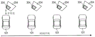
Fig. 5A is a diagram showing a time-series transition of superimposed images.
Fig. 5B is a diagram showing a time-series transition of the superimposed images.
Fig. 5C is a diagram showing a time-series transition of the superimposed images.
Fig. 6A is a diagram showing a distortion of the marker image.
Fig. 6B is a diagram showing a distortion of the marker image.
Fig. 6C is a diagram showing a distortion of the marker image.
Fig. 6D is a diagram showing a distortion of the marker image.
Fig. 6E is a diagram showing a distortion of the marker image.
Fig. 6F is a diagram showing a distortion of the marker image.
Fig. 7 is a diagram showing an example of display of a superimposed image.
Fig. 8 is a diagram showing an example of display of a superimposed image.
Fig. 9 is a diagram showing an example of display of superimposed images.
Fig. 10A is a diagram showing the boundary of a detected obstacle.
Fig. 10B is a diagram showing an example of display of the superimposed image.
Fig. 11A is a diagram showing an example of display of a superimposed image at a long distance.
Fig. 11B is a diagram showing an example of display of a superimposed image at a short distance.
Fig. 11C is a diagram showing an example of display of superimposed images at a very short distance.
Fig. 12 is a diagram showing an example of display of a superimposed image.
Fig. 13 is a diagram showing an example of display of a superimposed image.
Fig. 14A is a diagram showing an example of display of a superimposed image.
Fig. 14B is a diagram showing an example of display of the superimposed image.
Fig. 15A is a diagram showing an example of display of a superimposed image.
Fig. 15B is a diagram showing an example of display of a superimposed image.
Fig. 16 is a diagram showing an example of display of a superimposed image.
Fig. 17 is a diagram showing an example of display of a superimposed image.
Fig. 18A is a diagram showing an example of display of a superimposed image at a long distance.
Fig. 18B is a diagram showing an example of display of a superimposed image at a short distance.
Fig. 18C is a diagram showing an example of display of superimposed images at a very short distance.
Fig. 19A is a diagram in which an image of the own vehicle is arranged on an original image including a surrounding vehicle.
Fig. 19B is a diagram showing a boundary line of a nearby vehicle that is actually detected.
Fig. 19C is a diagram in which an icon indicating a vehicle is arranged in alignment with a detection line.
Fig. 19D is a diagram in which an icon representing a vehicle is superimposed on an original image of a surrounding vehicle.
Fig. 19E is a diagram in which an icon indicating the transparent color of the vehicle is superimposed on the original image of the surrounding vehicle.
Fig. 20 is a diagram in which icons indicating vehicles are superimposed on the original image of the surrounding vehicle.
Detailed Description
Hereinafter, embodiments of the present disclosure will be described with reference to the drawings. The present disclosure is not limited to the embodiments described below, and can be implemented in various forms.
[ description of the Structure of the on-vehicle display System ]
The configuration of the in-vehicle display system 10 according to the embodiment will be described with reference to fig. 1. The in-vehicle display system 10 is mounted on the vehicle 1, and assists driving by displaying an image created based on a video captured by a camera. As illustrated in fig. 1, the in-vehicle display system 10 includes an image processing unit 14, a camera 11 connected to the image processing unit 14, a distance measuring unit 12, and a display unit 13.
The camera 11 is an imaging device provided toward the periphery of the vehicle 1 such as the front, side, and rear. The camera 11 is configured to: the image processing unit 14 captures an image of a peripheral area of the vehicle 1 and outputs data indicating an image of the captured image (hereinafter also referred to as a captured image). The distance measuring unit 12 is a sensor configured to scan a range imaged by the camera 11, and to acquire information indicating a distance between an obstacle (for example, another vehicle, a pedestrian, a wall of a building, a pillar, or the like) existing in the scanned range and the vehicle 1, and a direction of the obstacle viewed from the vehicle 1. The distance measuring unit 12 is embodied by, for example, an ultrasonic sonar, a millimeter wave radar, a laser radar, a stereo camera, a monocular camera, a periphery monitoring camera, or the like. From the measurement result obtained by the distance measuring unit 12, the position of the obstacle, the shape of the boundary, the inclination of the surface, and the approximate width can be recognized.
The display unit 13 is a display configured to display the image information supplied from the image processing unit 14. The display unit 13 is provided, for example, in an instrument panel of the vehicle 1, so as to be easily visually confirmed by the driver of the vehicle 1.
The image processing unit 14 is an information processing device mainly including a CPU, a semiconductor memory such as a RAM, a ROM, and a flash memory, an input/output interface, and the like, which are not shown. The image processing unit 14 is embodied by, for example, a microcontroller or the like that integrates functions as a computer system. The function of the image processing unit 14 is realized by the CPU executing a program stored in a nonvolatile tangible storage medium such as a ROM or a semiconductor memory. The number of microcontrollers constituting the image processing unit 14 may be one or more. Note that the method of realizing the function of the image processing unit 14 is not limited to software, and some or all of the elements may be realized by hardware in which a logic circuit, an analog circuit, or the like is combined.
The image processing unit 14 executes the distance measurement processing and the obstacle display processing according to the above-described program. A detailed description of these processes will be described later.
[ description of distance measuring processing ]
The procedure of the distance measurement process executed by the image processing unit 14 will be described with reference to the flowchart of fig. 2. This distance measurement process is repeatedly executed for each predetermined control cycle during the operation of the in-vehicle display system 10.
In S100, the image processing unit 14 measures the distance to the obstacle existing in the periphery of the vehicle 1 using the distance measuring unit 12, and acquires the position information about the obstacle. Specifically, the image processing unit 14 continuously scans the periphery of the vehicle 1 with a detection wave of radar, sonar, or the like constituting the distance measuring unit 12, and receives a reflected wave from an obstacle, thereby acquiring position information indicating the distribution of distances to obstacles present in the scanned range. Alternatively, the position information indicating the distribution of the distances to the obstacle may be acquired from an image captured by a stereo camera, a monocular camera, a periphery monitoring camera, or the like by a known image recognition technique of recognizing the distance to the object.
In S102, the image processing unit 14 stores the positional information acquired in S100, that is, the information indicating the distribution of the distances between the vehicle 1 and the obstacle, in the memory in the image processing unit 14. After S102, the image processing section 14 returns the process to S100.
[ Explanation of obstacle display treatment ]
The procedure of the obstacle display processing executed by the image processing unit 14 will be described with reference to the flowchart of fig. 3. This obstacle display process is repeatedly executed for each predetermined control cycle in parallel with the distance measurement process described above during the operation of the in-vehicle display system 10.
In S200, the image processing unit 14 acquires the latest captured image of 1 frame from the camera 11. In S202, the image processing unit 14 performs coordinate conversion on the coordinates of the pixels constituting the captured image acquired in S200 by using a known bird ' S eye view conversion process, and converts the captured image of the camera 11 into a bird ' S eye view image simulating a bird ' S eye view from a viewpoint set above the vehicle 1.
In S204, the image processing unit 14 reads the latest position information acquired in the distance measurement process (see fig. 2) from the memory. In S206, the image processing unit 14 creates a logo image that is a pattern for specifying the obstacle present on the bird 'S-eye view image, based on the position information read in S204 and the shape of the obstacle reflected on the bird' S-eye view image created in S202. Specific attributes of the identification image produced here will be described later. In S208, the image processing unit 14 creates a superimposed image in which the logo image created in S206 is superimposed at a position corresponding to the obstacle shown on the bird' S eye view image created in S202, and displays the created superimposed image on the display unit 13.
Further, the image processing unit 14 is configured to: the superimposed image is created by changing the attribute of the marker image superimposed on the image of the obstacle, based on the state of the shape, inclination, position, color, and the like of the obstacle specified from the captured image by the camera 11 or specified by the distance measuring unit 12. The attribute of the identification image referred to herein is, for example, the shape, size, inclination, flicker, color, density, transparency, and the like of the pattern. A specific application example of the marker image superimposed on the image of the obstacle will be described below with reference to fig. 4 to 20.
(FIG. 4: application example 1)
Fig. 4A, 4B, and 4C are examples of superimposed images displayed on the display unit 13. A vehicle image 101, which is a virtual image showing the appearance of the vehicle 1 (i.e., the own vehicle), is arranged in these superimposed images. In the following, the vehicle image 101 is assumed to be arranged similarly for the superimposed image explained in the other application examples. The vehicle image 101 is rendered by the image processing unit 14 when the captured image by the camera 11 is bird's-eye-converted. Further, the image processing unit 14 draws a logo image indicating a pattern of an obstacle appearing in the bird's eye view image on the superimposed image.
In the example of fig. 4A, a situation is assumed in which an image 201 of an elongated columnar obstacle is reflected on the front side of the vehicle image 101. In the example of fig. 4A, the image processing unit 14 creates a marker image 301 formed of a plate-like pattern having a width approximately equal to the width of the obstacle image 201. Then, the image processing unit 14 creates a superimposed image by superimposing the logo image 301 and the obstacle image 201 on the bird's eye image in alignment.
In the example of fig. 4B, a situation is assumed in which an image 202 of a wall-like obstacle having a width approximately equal to that of the vehicle 1 is displayed on the front surface side of the vehicle image 101. In the example of fig. 4B, the image processing unit 14 creates a logo image 302 formed of a plate-like pattern having a width larger than that of the example of fig. 4A, based on the width of the reflected obstacle. Then, the image processing unit 14 creates a superimposed image by superimposing the logo image 302 and the obstacle image 202 on the bird's eye view image in alignment.
In the example of fig. 4C, a situation is assumed in which an image 203 of a wall-like obstacle facing in a state of being inclined with respect to the front direction plane of the vehicle image 101 is displayed diagonally in front of the vehicle image 101. In the example of fig. 4C, the image processing unit 14 creates a logo image 303 formed of a pattern in which the plate-like surface is inclined, in alignment with the inclination of the obstacle image 203 with respect to the front direction of the vehicle image 101. Then, the image processing unit 14 creates a superimposed image by superimposing the marker image 303 and the obstacle image 203 on the bird's eye image in alignment.
In each of the examples of fig. 4A, 4B, and 4C, the image processing unit 14 is configured to: the orientation of the logo image formed by the plate-like pattern can be changed according to the inclination of the portions of the obstacles 201, 202, and 203 facing the vehicle 1 in the road surface direction. Specifically, the image processing unit 14 recognizes the inclination in the road surface direction of the portion where the obstacles 201, 202, and 203 face the vehicle 1 based on the shape of the boundary of the obstacles 201, 202, and 203 indicated by the position information acquired by the distance measuring unit 12. The image processing unit 14 then creates the marker images 301, 302, 303, which are composed of the geometric patterns having the same inclination as the inclination of the obstacles 201, 202, 203 in the coordinate system of the bird's eye view image, and superimposes the marker images on the images of the obstacles 201, 202, 203.
(FIG. 5: application example 2)
The image processing unit 14 may be configured to periodically flash the marker image displayed in superimposition with the obstacle image. As illustrated in fig. 5A, 5B, and 5C, the length of the period for blinking the marker image 304 may be changed according to the distance between the vehicle 1 and the obstacle 204. In this way, the driver can reliably grasp the distance to the obstacle.
Fig. 5A is an example of a time series showing the time course of the superimposed images displayed by the image processing unit 14 in a situation where the distance between the vehicle 1 and the obstacle is relatively long. In the example of fig. 5A, the image processing unit 14 displays a superimposed image in which the marker image 304 superimposed on the obstacle image 204 is caused to blink at a relatively long cycle.
The example of fig. 5B is a time series showing the time course of the superimposed image displayed by the image processing unit 14 in a situation where the distance between the vehicle 1 and the obstacle is relatively short (i.e., closer to the example of fig. 5A). In the example of fig. 5B, the image processing unit 14 displays a superimposed image in which the marker image 304 superimposed on the obstacle image 204 is caused to blink at a shorter cycle than in the example of fig. 5A.
The example of fig. 5C is a time series showing the time course of the superimposed images displayed by the image processing unit 14 in a situation where the distance between the vehicle 1 and the obstacle is very short (i.e., closer than the example of fig. 5B). In the example of fig. 5C, the image processing unit 14 displays a superimposed image in which the marker image 304 superimposed on the obstacle image 204 is displayed continuously or blinks at a shorter cycle than in the example of fig. 5B.
(FIG. 6: application example 3)
As illustrated in fig. 6A, 6B, 6C, 6D, 6E, and 6F, the image processing unit 14 may be configured to superimpose a logo image, which may include various shapes of graphics, symbols, icons, and character information, on the image of the obstacle.
The example of fig. 6A is an example of a superimposed image in which a marker image 305 formed of a plate-like pattern is superimposed along a surface of the obstacle image 205. The example of fig. 6B is an example of a superimposed image in which a marker image 306 formed of a zigzag pattern is superimposed along a surface of the obstacle image 205. The example of fig. 6C is an example of a superimposed image in which a marker image 307 formed of a wavy line pattern is superimposed along the surface of the obstacle image 205.
The example of fig. 6D is an example of a superimposed image in which a marker image 308 formed of a pattern in a dot row is superimposed along the surface of the obstacle image 205. The example of fig. 6E is an example of a superimposed image in which a marker image 309 including an icon including a symbol that urges attention is superimposed along the face of the obstacle image 205. The example of fig. 6F is an example of a superimposed image in which a marker image 310 composed of character information indicating a distance to an obstacle is superimposed along a surface of the obstacle image 205.
(FIG. 7: application example 4)
The image processing unit 14 may be configured to: the logo image is disposed for an obstacle that matches a range in which the vehicle width is extended in the front-rear direction of the vehicle length, with respect to the travel path on which the vehicle 1 is predicted to travel. In this case, the marker image may not be displayed even if an obstacle is detected in the other range. Specifically, the image processing unit 14 predicts the travel path of the vehicle 1 by acquiring vehicle information indicating the steering condition of the vehicle 1 and the like, and determines the range of the predicted travel path and the range of the vehicle length in the front-rear direction on the bird's eye view image based on the vehicle width, the vehicle length, and the like of the vehicle 1 registered in advance.
The example of fig. 7 is an example of a superimposed image displayed in a situation where a travel path in which the vehicle 1 turns left is predicted. In the example of fig. 7, in the obstacle image 206, the marker image 311 is arranged along a lateral range that coincides with a range of the trajectory of the predicted travel path in which the vehicle 1 curves leftward and a range in which the vehicle width of the vehicle 1 is projected in the front direction. In this way, the driver can easily and clearly present the obstacle in the range where the vehicle 1 is likely to contact.
(FIG. 8: application example 5)
The image processing unit 14 may be configured to: in consideration of the possibility that the vehicle 1 may contact an obstacle, a logo image is arranged to target an obstacle that matches a range based on the vehicle width of the vehicle 1. In this case, as illustrated in fig. 8, the identification image may be arranged in a range slightly wider than the vehicle width of the vehicle 1.
The example of fig. 8 is an example of a superimposed image displayed in a situation where an obstacle exists diagonally in front of the vehicle 1. In the example of fig. 8, the logo image 312 is disposed in a portion of the obstacle image 207 that corresponds to a display range in which a range in which the vehicle width of the vehicle 1 is projected in the front direction is enlarged by a predetermined distance to the left and right. In this way, the driver can easily and clearly present the obstacle in the range where the vehicle 1 is likely to contact.
(FIG. 9: application example 6)
The image processing unit 14 may be configured to: the identification image relating to the obstacle is arranged in a range larger than the width of the detection line with respect to a boundary line (hereinafter, also referred to as a detection line) indicating the shape of the obstacle detected by the radar or sonar of the distance measuring unit 12. Specifically, the image processing unit 14 specifies the width of the detection line of the obstacle indicated by the position information acquired by the distance measuring unit 12, and specifies the range in which the marker image is arranged based on the width of the detection line.
The example of fig. 9 is an example of a superimposed image displayed in a situation where an obstacle exists in front of the vehicle. In the example of fig. 9, the marker image 313 is arranged in a portion of the obstacle image 208 corresponding to a display range in which the width of the detection line actually detected is enlarged by a predetermined distance to the left and right. In this way, even when the actual width of the obstacle is larger than the width of the detection line, the scale of the obstacle can be presented to the driver with certainty.
(FIG. 10: application example 7)
The image processing unit 14 may be configured to: the boundary of an obstacle detected by the radar or sonar of the distance measuring unit 12 is recognized from the bird's eye view image by image recognition, and a marker image relating to the obstacle is arranged along the recognized boundary.
Specifically, as illustrated in fig. 10A, the image processing unit 14 extracts feature amounts such as edges from an image area around the detection line of the obstacle image 209 reflected on the bird's eye view image, and detects the boundary of the obstacle in the vertical direction based on the extracted feature amounts. Further, as illustrated in fig. 10B, the image processing unit 14 superimposes the marker image 314 along the width of the boundary of the obstacle image 209 on the obstacle image 209. In this way, even when the actual width of the obstacle is larger than the width of the detection line, the scale of the obstacle can be presented to the driver with certainty.
(FIG. 11: application example 8)
The image processing unit 14 may be configured to: the attribute (for example, shape, size, color, transmittance, and the like) of the logo image superimposed on the image of the obstacle is changed according to the distance between the vehicle 1 and the obstacle. In this way, the driver can reliably grasp the distance to the obstacle.
The example of fig. 11A is an example of a superimposed image displayed by the image processing unit 14 in a situation where the distance between the vehicle 1 and the obstacle is relatively long. In the example of fig. 11A, the image processing unit 14 displays a superimposed image in which a relatively small logo image 315 is superimposed on the obstacle image 210.
The example of fig. 11B is an example of a superimposed image displayed by the image processing unit 14 in a situation where the distance between the vehicle 1 and the obstacle is relatively short (i.e., closer than the example of fig. 11A). In the example of fig. 11B, the image processing unit 14 displays a superimposed image in which the marker image 316 having a shape larger than that of the example of fig. 11A is superimposed on the obstacle image 210. At this time, the image processing unit 14 may change the color or transmittance of the logo image 316 to be more emphasized than the logo image 315 in fig. 11A.
The example of fig. 11C is an example of a superimposed image displayed by the image processing unit 14 in a situation where the distance between the vehicle 1 and the obstacle is very short (i.e., closer than the example of fig. 11B). In the example of fig. 11C, the image processing unit 14 displays a superimposed image in which the marker image 317 having a larger shape than that of the example of fig. 11B is superimposed on the obstacle image 210. At this time, the image processing unit 14 may be changed to emphasize the color or transmittance of the logo image 317 compared with the logo image 316 in fig. 11B.
(FIG. 12: application example 9)
The image processing unit 14 may be configured to: the marker image superimposed on the image of the obstacle is drawn so as to extend to the outer edge of the display range of the superimposed image in the direction above the obstacle. Specifically, as illustrated in fig. 12, the image processing unit 14 draws the marker image 318 disposed on the obstacle image 211 in a shape extending to the upper end of the display range of the superimposed image in a direction corresponding to the upper side of the obstacle image 211. In this way, the driver can be presented with the logo image relating to the obstacle so as to emphasize the height of the obstacle.
(FIG. 13: application example 10)
The shape of the logo image superimposed on the image of the obstacle on the bird's-eye view image is configured to extend radially in consideration of distortion of the image that occurs when the image processing unit 14 converts the captured image by the camera 11 into the bird's-eye view image (for example, the image extends radially as it is farther from the center). Specifically, as illustrated in fig. 13, the image processing unit 14 draws the marker image 318 superimposed on the obstacle image 211 in a shape extending radially with the image position on the bird's eye view image corresponding to the position of the camera 11 as the center. This reduces the sense of discomfort given to the driver.
(FIG. 14: application example 11)
The image processing unit 14 may be configured to: the marker image superimposed on the image of the obstacle is drawn so as to emphasize the lower end side of the obstacle. Specifically, as illustrated in fig. 14A and 14B, the image processing unit 14 draws the pattern constituting the marker images 320 and 321 by changing the color, shade, and transmittance continuously or stepwise from the upper end side to the lower end side of the obstacle image 213, thereby emphasizing the lower end side of the obstacle image 213. In this way, the logo image can be displayed so as to emphasize a portion below the obstacle that may come into contact with the vehicle 1.
(FIG. 15: application example 12)
The image processing unit 14 may be configured to: the color of the obstacle is recognized from the captured image, and a logo image using a color corresponding to a complementary color of the recognized obstacle is drawn. Specifically, as illustrated in fig. 15A and 15B, the marker images 322 and 323 formed of a pattern having a complementary color relationship with the colors of the obstacle images 214 and 215 are superimposed on the obstacle images 214 and 215. In this way, the obstacle image and the logo image can be mutually dislocated, and the visibility of the driver can be improved.
(FIG. 16: application example 13)
The image processing unit 14 may be configured to: when it is estimated that the obstacle detected by the distance measuring unit 12 is an inclined surface, the marker image is arranged in a range closer to the vehicle 1 than the detection line indicating the boundary of the detected obstacle.
For example, when a slope such as an uphill slope is detected by the radar or sonar of the distance measuring unit 12, the slope may be directed to a region below the lower limit of the detection range in the longitudinal direction of the radar or sonar and may not be detected next by the vehicle 1. Therefore, as illustrated in fig. 16, the image processing unit 14 arranges the marker image 324 in a range including a region closer to the vehicle image 101 than the actual detection line with respect to the image 216 of the slope detected as the obstacle. In this way, the driver can be alerted to a portion of the slope that is not detected by the radar or sonar of the distance measuring unit 12.
(FIG. 17: application example 14)
The image processing unit 14 may be configured to: the marker image superimposed on the image of the obstacle is drawn so as to emphasize the area actually detected by the distance measuring unit 12 over the other areas. Specifically, as illustrated in fig. 17, the image processing unit 14 displays the marker image 325A formed of a plate-like pattern on the obstacle image 217, and displays the emphasized image 325B on the image area corresponding to the area detected by the radar or sonar of the distance measuring unit 12. The emphasized image 325B is assumed to be composed of a pattern drawn using a color, density, and transmittance emphasized by the marker image 325A. In this way, the driver can be alerted to the boundary of the obstacle.
(FIG. 18: application example 15)
The image processing unit 14 may be configured to display a grid-like line (hereinafter, referred to as a grid line) serving as a reference of the distance between the vehicle 1 and the obstacle in the superimposed image in accordance with the distance between the vehicle 1 and the obstacle. In addition, the fineness of the grid lines may be changed according to the distance between the vehicle 1 and the obstacle. In this way, the driver can reliably grasp the distance to the obstacle.
The example of fig. 18A is an example of a superimposed image displayed by the image processing unit 14 in a situation where the distance between the vehicle 1 and the obstacle is relatively long. In the example of fig. 18A, the image processing unit 14 displays a superimposed image in which the marker image 326 is superimposed on the obstacle image 218. However, at this distance, a grid line that is a reference of the distance between the vehicle 1 and the obstacle is not shown.
The example of fig. 18B is an example of a superimposed image displayed by the image processing unit 14 in a situation where the distance between the vehicle 1 and the obstacle is relatively short (i.e., closer than the example of fig. 18A). In the example of fig. 18B, the image processing unit 14 displays a superimposed image in which the marker image 327 is superimposed on the obstacle image 218 and grid lines formed by relatively large grids are drawn around the vehicle image 101 and the obstacle image 218.
The example of fig. 18C is an example of a superimposed image displayed by the image processing unit 14 in a situation where the distance between the vehicle 1 and the obstacle is very short (i.e., closer than the example of fig. 18B). In the example of fig. 18C, the image processing unit 14 displays a superimposed image in which the marker image 328 is superimposed on the obstacle image 218 and grid lines formed of a finer grid than that of the example of fig. 18B are drawn around the vehicle image 101 and the obstacle image 218.
(FIG. 19: application example 16)
The image processing unit 14 may be configured to: when it is estimated that the obstacle detected by the distance measuring unit 12 is a vehicle, a logo image formed of an icon imitating the vehicle is superimposed and displayed so as to be aligned with the direction and size of the vehicle detected as the obstacle. This enables the driver to reliably recognize another vehicle present in the periphery of the vehicle 1.
Fig. 19A shows an example in which 2 images 401 and 402 of other vehicles are displayed around the vehicle image 101 corresponding to the vehicle 1 in the bird's eye image created from the captured image of the camera 11. Fig. 19B shows detection lines indicating the boundaries of another vehicle actually detected by the distance measuring unit 12 in the situation illustrated in fig. 19A.
As illustrated in fig. 19C, the image processing unit 14 creates marker images 501 and 502 made of icons simulating vehicles in accordance with the shape and inclination of the detection lines. Note that the marker images 501 and 502 created in the example of fig. 19C are drawn with opaque colors. As illustrated in fig. 19D, the image processing unit 14 displays a superimposed image in which the created logo images 501 and 502 are superimposed on the images 401 and 402 of the other vehicles, respectively.
Alternatively, as illustrated in fig. 19E, the image processing unit 14 may be configured to: the inside transparent logo images 601, 602 of the pattern representing the vehicle only by the outline are superimposed with the images 401, 402 of the other vehicles.
(FIG. 20: application example 17)
The image processing unit 14 may be configured to use a single representative color obtained from an original image of another vehicle as an object to which the logo image is superimposed when drawing the logo image formed of an icon imitating the vehicle. Specifically, as illustrated in fig. 20, the image processing unit 14 extracts a specific color from the image 403 of the other vehicle shown in the bird's eye view image, and displays a logo image 503 drawn using the extracted color so as to be superimposed on the image 403 of the other vehicle. In this way, even when another vehicle detected as an obstacle draws a complicated pattern or when a complicated pattern appears by receiving light or the like that has passed through a barrier of a three-dimensional parking lot, the logo image can be displayed in a simple and easily visible manner.
[ Effect ]
According to the in-vehicle display system of the embodiment, the following effects are obtained.
The pattern representing the obstacle, that is, the attribute such as the orientation and shape of the logo image can be changed according to the shape such as the inclination and size of the obstacle detected in the periphery of the vehicle 1. In addition, the display mode such as the size, color, and blinking of the marker image can be freely changed according to the distance from the obstacle. In this way, the driver of the vehicle can easily grasp the state of the obstacle by observing the superimposed image in which the marker image is superimposed on the image of the obstacle.
[ correspondence with the structure of the embodiment ]
The image processing unit 14 corresponds to an example of the display control device. The processing of S200 and S202 performed by the image processing unit 14 corresponds to an example of the processing performed by the image acquisition unit. The processing of S206 executed by the image processing unit 14 corresponds to an example of the processing of the obstacle specifying unit and the control unit.
[ modified examples ]
The functions of one component of each of the above embodiments may be shared by a plurality of components, or one component may perform the functions of a plurality of components. In addition, a part of the structure of each of the above embodiments may be omitted. In addition, at least a part of the structure of each of the above embodiments may be added to or replaced with the structure of the other above embodiments. All the aspects included in the technical concept defined by the terms described in the claims are embodiments of the present disclosure.
For example, in application example 1 (see fig. 4) described above, an example is described in which the shape such as the inclination and the width of the logo image of the image superimposed on the obstacle can be changed according to the orientation and the width of the obstacle. Further, the attribute such as the color or pattern of the marker image may be changed according to the inclination of the obstacle.
In the above-described embodiment, an example has been described in which, after converting the captured image by the camera 11 into a bird's-eye view image, a logo image is superimposed on the image of the obstacle on the converted bird's-eye view image. However, the identification image may be superimposed on the captured image itself by the camera 11, without being limited to the bird's eye view image. Alternatively, the tag image may be superimposed on an image converted into an image from a viewpoint different from the bird's eye view image.
The present disclosure can also be implemented in various forms such as a program for causing a computer to function as the image processing unit 14, a nonvolatile physical recording medium such as a semiconductor memory in which the program is recorded, and the like.
Claims (16)
1. A display control device that displays, on a display device located in a vehicle, an image created based on an image obtained by taking a predetermined range of the periphery of the vehicle with a camera mounted on the vehicle, the display control device comprising:
an image acquisition unit configured to acquire a peripheral image that is an image based on an image captured by the camera;
an obstacle specifying unit configured to: determining a shape of an obstacle including at least an inclination in a road surface direction of a portion of the obstacle facing the vehicle with respect to the obstacle determined from a range reflected by the peripheral image acquired by the image acquisition unit; and
a control unit configured to: creating a superimposed image in which a logo image created as a pattern showing the obstacle is superimposed on the peripheral image at a position corresponding to the obstacle, for the obstacle specified by the obstacle specifying unit, and displaying the created superimposed image on the display device,
the control unit is configured to: the attribute of the identification image is changeable according to the inclination of the obstacle determined by the obstacle determining section.
2. A display control device that displays, on a display device located in a vehicle, an image created based on an image obtained by taking a predetermined range of the periphery of the vehicle with a camera mounted on the vehicle, the display control device comprising:
an image acquisition unit configured to acquire a peripheral image that is an image based on an image captured by the camera;
an obstacle specifying unit configured to: determining a shape or an inclination of an obstacle determined from a range of the peripheral image acquired by the image acquisition unit; and
a control unit configured to: creating a superimposed image in which a logo image created as a pattern showing the obstacle is superimposed on the peripheral image at a position corresponding to the obstacle, for the obstacle specified by the obstacle specifying unit, and displaying the created superimposed image on the display device,
the control unit is configured to: the attribute of the identification image is made variable according to the shape or inclination of the obstacle determined by the obstacle determining section.
3. The display control apparatus according to claim 1 or 2,
the control unit is configured to: the identification image is displayed in an inclined manner in alignment with the inclination of the obstacle determined by the obstacle determining section.
4. The display control apparatus according to claim 1 or 2,
the control unit is configured to: the display form of the logo image superimposed on the obstacle is changeable according to the distance measured by the distance measuring unit configured to measure the distance between the obstacle and the vehicle.
5. The display control apparatus according to claim 1 or 2,
the control unit is configured to: the marker image is arranged on an image of an obstacle that is present in a range on a trajectory predicted to be traveled by the vehicle among the obstacles specified by the obstacle specifying unit and in a range in which the vehicle width of the vehicle is projected in front of or behind the vehicle.
6. The display control apparatus according to claim 1 or 2,
the control unit is configured to: the marker image is arranged on an image of an obstacle existing in a range in which a vehicle width of the vehicle is enlarged by a certain amount is projected in front of or behind the vehicle among the obstacles specified by the obstacle specifying unit.
7. The display control apparatus according to claim 1 or 2,
the control unit is configured to: the marker image is arranged in a range in which the boundary of the obstacle specified by the obstacle specifying unit is enlarged.
8. The display control apparatus according to claim 1 or 2,
the obstacle specifying unit is configured to: determining a boundary of an obstacle on the peripheral image based on a feature amount of the peripheral image based on an image portion of the peripheral image corresponding to a range in which the obstacle is detected by an object sensor that detects the obstacle present in the periphery of the vehicle,
the control unit is configured to: the marker image is arranged along the boundary of the obstacle determined by the obstacle determining section.
9. The display control apparatus according to claim 1 or 2,
the control unit is configured to: the marker image is drawn so as to be directed upward of the obstacle to reach an outer edge portion of a display range of the superimposed image.
10. The display control apparatus according to claim 1 or 2,
the image acquisition unit is configured to: acquiring a bird's-eye view image changed to an image representing an image captured by the camera at a bird's-eye view as the peripheral image,
the control unit is configured to display the banner image superimposed on the bird's-eye view image, and draw the banner image in a shape radially expanded around a position of the camera.
11. The display control apparatus according to claim 1 or 2,
the control unit is configured to: the identification image is depicted in a manner that the lower end side of the obstacle is emphasized and displayed over the upper end side of the obstacle.
12. The display control apparatus according to claim 1 or 2,
the control unit is configured to: in a case where a display color of a standard for the logo image conforms to a color of the same color system as that of the obstacle, the logo image is depicted using a display color different from the display color of the standard.
13. The display control apparatus according to claim 1 or 2,
the control unit is configured to: and in the case where the obstacle conforms to a slope, extending the range of the identification image closer to the vehicle than the area where the obstacle is detected.
14. The display control apparatus according to claim 1 or 2,
the control unit is configured to draw the marker image in such a manner that an image portion of the peripheral image corresponding to a range in which an obstacle is detected by an obstacle sensor for detecting an obstacle is displayed in a highlighted manner with respect to another image portion corresponding to the obstacle.
15. The display control apparatus according to claim 1 or 2,
the obstacle specifying unit is configured to recognize another vehicle as the obstacle,
the control unit is configured to: the other vehicle recognized by the obstacle specifying unit is arranged such that the marker image, which is a pattern indicating a vehicle, is aligned with the inclination of the other vehicle at a position on the surrounding image corresponding to the other vehicle.
16. The display control apparatus according to claim 15,
the control unit is configured to: the logo image is a pattern of a vehicle drawn by partially using a transparent color or a pattern of a vehicle drawn by using a color of the other vehicle recognized from the surrounding image.
Applications Claiming Priority (3)
| Application Number | Priority Date | Filing Date | Title |
|---|---|---|---|
| JP2016088183A JP6595401B2 (en) | 2016-04-26 | 2016-04-26 | Display control device |
| JP2016-088183 | 2016-04-26 | ||
| PCT/JP2017/016367 WO2017188247A1 (en) | 2016-04-26 | 2017-04-25 | Display control apparatus |
Publications (2)
| Publication Number | Publication Date |
|---|---|
| CN109076197A CN109076197A (en) | 2018-12-21 |
| CN109076197B true CN109076197B (en) | 2020-09-04 |
Family
ID=60159728
Family Applications (1)
| Application Number | Title | Priority Date | Filing Date |
|---|---|---|---|
| CN201780025745.5A Active CN109076197B (en) | 2016-04-26 | 2017-04-25 | Display control device |
Country Status (5)
| Country | Link |
|---|---|
| US (2) | US11064151B2 (en) |
| JP (1) | JP6595401B2 (en) |
| CN (1) | CN109076197B (en) |
| DE (1) | DE112017002189T5 (en) |
| WO (1) | WO2017188247A1 (en) |
Families Citing this family (9)
| Publication number | Priority date | Publication date | Assignee | Title |
|---|---|---|---|---|
| JP6595401B2 (en) | 2016-04-26 | 2019-10-23 | 株式会社Soken | Display control device |
| JP2018005091A (en) * | 2016-07-06 | 2018-01-11 | 富士通株式会社 | Display control program, display control method and display controller |
| JP6541097B2 (en) * | 2017-10-10 | 2019-07-10 | マツダ株式会社 | Vehicle display device |
| CN110197097B (en) * | 2018-02-24 | 2024-04-19 | 北京图森智途科技有限公司 | Harbor district monitoring method and system and central control system |
| JP7189695B2 (en) * | 2018-08-07 | 2022-12-14 | 日立Astemo株式会社 | Driving support device |
| JP6696558B1 (en) * | 2018-12-26 | 2020-05-20 | 株式会社Jvcケンウッド | Vehicle recording control device, vehicle recording device, vehicle recording control method, and program |
| US11829128B2 (en) | 2019-10-23 | 2023-11-28 | GM Global Technology Operations LLC | Perception system diagnosis using predicted sensor data and perception results |
| USD1015342S1 (en) * | 2021-01-08 | 2024-02-20 | Sony Group Corporation | Display screen or portion thereof with animated graphical user interface |
| DE102022205393A1 (en) * | 2022-05-30 | 2023-11-30 | Volkswagen Aktiengesellschaft | Method for operating an information system, computer program product and vehicle |
Citations (8)
| Publication number | Priority date | Publication date | Assignee | Title |
|---|---|---|---|---|
| JP2007295043A (en) * | 2006-04-20 | 2007-11-08 | Matsushita Electric Ind Co Ltd | Vehicle periphery monitoring apparatus |
| CN201154669Y (en) * | 2008-01-03 | 2008-11-26 | 李植滔 | Visual distance-measuring system for backing |
| CN102652327A (en) * | 2010-02-24 | 2012-08-29 | 爱信精机株式会社 | Vehicle surroundings monitoring device |
| CN102696225A (en) * | 2010-01-19 | 2012-09-26 | 爱信精机株式会社 | Vehicle periphery monitoring device |
| CN102754138A (en) * | 2010-03-16 | 2012-10-24 | 三菱电机株式会社 | Road-Vehicle cooperative driving safety support device |
| CN103692973A (en) * | 2012-09-27 | 2014-04-02 | 富士通天株式会社 | Image generating apparatus, image display system and image generating method |
| CN103733239A (en) * | 2011-11-01 | 2014-04-16 | 爱信精机株式会社 | Obstacle alert device |
| CN105007449A (en) * | 2014-04-25 | 2015-10-28 | 日立建机株式会社 | Vehicle peripheral obstacle notification system |
Family Cites Families (38)
| Publication number | Priority date | Publication date | Assignee | Title |
|---|---|---|---|---|
| JP3626613B2 (en) | 1998-11-13 | 2005-03-09 | 日産車体株式会社 | Obstacle detection display |
| JP3645196B2 (en) * | 2001-02-09 | 2005-05-11 | 松下電器産業株式会社 | Image synthesizer |
| JP2002359839A (en) * | 2001-03-29 | 2002-12-13 | Matsushita Electric Ind Co Ltd | Method and device for displaying image of rearview camera |
| JPWO2004083889A1 (en) * | 2003-03-20 | 2006-06-22 | 松下電器産業株式会社 | Obstacle detection device |
| DE102004009924A1 (en) * | 2004-02-23 | 2005-09-01 | Valeo Schalter Und Sensoren Gmbh | Picture processing method for motor vehicle, involves processing picture based on determination of real position of obstacle in vicinity of vehicle and determination of position from picture provided by camera device |
| US8885045B2 (en) * | 2005-08-02 | 2014-11-11 | Nissan Motor Co., Ltd. | Device and method for monitoring vehicle surroundings |
| JP4720386B2 (en) * | 2005-09-07 | 2011-07-13 | 株式会社日立製作所 | Driving assistance device |
| JP4887980B2 (en) * | 2005-11-09 | 2012-02-29 | 日産自動車株式会社 | VEHICLE DRIVE OPERATION ASSISTANCE DEVICE AND VEHICLE WITH VEHICLE DRIVE OPERATION ASSISTANCE DEVICE |
| JP4687411B2 (en) * | 2005-11-15 | 2011-05-25 | 株式会社デンソー | Vehicle peripheral image processing apparatus and program |
| JP2008219063A (en) * | 2007-02-28 | 2008-09-18 | Sanyo Electric Co Ltd | Apparatus and method for monitoring vehicle's surrounding |
| US20090096937A1 (en) * | 2007-08-16 | 2009-04-16 | Bauer Frederick T | Vehicle Rearview Assembly Including a Display for Displaying Video Captured by a Camera and User Instructions |
| JP4458138B2 (en) * | 2007-09-18 | 2010-04-28 | 株式会社デンソー | Vehicle periphery monitoring device |
| JP2012040883A (en) * | 2008-12-19 | 2012-03-01 | Panasonic Corp | Device for generating image of surroundings of vehicle |
| JP5240149B2 (en) * | 2009-09-28 | 2013-07-17 | 三菱自動車工業株式会社 | Vehicle periphery monitoring device |
| JP2011109170A (en) * | 2009-11-12 | 2011-06-02 | Clarion Co Ltd | Vehicle surrounding display device and vehicle surrounding display method |
| WO2011145141A1 (en) * | 2010-05-19 | 2011-11-24 | 三菱電機株式会社 | Vehicle rear-view observation device |
| JP5052707B2 (en) * | 2010-06-15 | 2012-10-17 | 三菱電機株式会社 | Vehicle periphery monitoring device |
| FR2968262B1 (en) * | 2010-12-06 | 2012-11-23 | Peugeot Citroen Automobiles Sa | ASSISTING DEVICE FOR ENABLING A DRIVER OF A VEHICLE TO CHECK FROM A PARKING AREA EXIT |
| JP5724446B2 (en) * | 2011-02-21 | 2015-05-27 | 日産自動車株式会社 | Vehicle driving support device |
| JP2012244600A (en) * | 2011-05-24 | 2012-12-10 | Fujitsu Ten Ltd | Image display system, image processing apparatus, and image display method |
| EP2717238B1 (en) * | 2011-06-02 | 2016-11-09 | Toyota Jidosha Kabushiki Kaisha | Vehicular field of view assistance device |
| WO2012172923A1 (en) * | 2011-06-16 | 2012-12-20 | アイシン精機株式会社 | Vehicle periphery monitoring device |
| US9605971B2 (en) * | 2011-06-17 | 2017-03-28 | Robert Bosch Gmbh | Method and device for assisting a driver in lane guidance of a vehicle on a roadway |
| WO2014076769A1 (en) * | 2012-11-13 | 2014-05-22 | 株式会社東芝 | Detection device, method, and program |
| US10179543B2 (en) * | 2013-02-27 | 2019-01-15 | Magna Electronics Inc. | Multi-camera dynamic top view vision system |
| JP5991647B2 (en) * | 2013-03-28 | 2016-09-14 | 株式会社デンソー | Perimeter monitoring and control device for vehicles |
| JP2014191763A (en) * | 2013-03-28 | 2014-10-06 | Fujitsu Ltd | Device, system, program, and method for recognizing vehicle |
| JP6287237B2 (en) * | 2014-01-17 | 2018-03-07 | 株式会社リコー | Information processing apparatus, information processing method, and program |
| JP2015184874A (en) * | 2014-03-24 | 2015-10-22 | 株式会社東芝 | Moving body operation support system, moving body operation support method and moving body operation support program |
| JP6075331B2 (en) * | 2014-06-13 | 2017-02-08 | トヨタ自動車株式会社 | Vehicle lighting device |
| JP6287704B2 (en) * | 2014-09-04 | 2018-03-07 | 株式会社デンソー | Driving assistance device |
| JP6464673B2 (en) | 2014-10-31 | 2019-02-06 | 株式会社Ihi | Obstacle detection system and railway vehicle |
| GB2532953A (en) * | 2014-12-02 | 2016-06-08 | Ibm | Overlay display |
| JP6542539B2 (en) * | 2015-02-10 | 2019-07-10 | クラリオン株式会社 | Vehicle accessibility determination device |
| US9505404B2 (en) * | 2015-04-10 | 2016-11-29 | Jaguar Land Rover Limited | Collision avoidance system |
| CN107848465B (en) * | 2015-05-06 | 2021-06-01 | 麦格纳镜片美国有限公司 | Vehicle vision system with blind zone display and warning system |
| FR3036353B1 (en) * | 2015-05-20 | 2018-12-07 | Valeo Comfort And Driving Assistance | METHOD FOR INTERACTIVELY CONTROLLING AUTOMATIC PARKING OF A MOTOR VEHICLE USING A MOBILE TERMINAL |
| JP6595401B2 (en) | 2016-04-26 | 2019-10-23 | 株式会社Soken | Display control device |
-
2016
- 2016-04-26 JP JP2016088183A patent/JP6595401B2/en active Active
-
2017
- 2017-04-25 DE DE112017002189.8T patent/DE112017002189T5/en active Pending
- 2017-04-25 WO PCT/JP2017/016367 patent/WO2017188247A1/en active Application Filing
- 2017-04-25 US US16/096,042 patent/US11064151B2/en active Active
- 2017-04-25 CN CN201780025745.5A patent/CN109076197B/en active Active
-
2021
- 2021-06-14 US US17/346,662 patent/US11750768B2/en active Active
Patent Citations (8)
| Publication number | Priority date | Publication date | Assignee | Title |
|---|---|---|---|---|
| JP2007295043A (en) * | 2006-04-20 | 2007-11-08 | Matsushita Electric Ind Co Ltd | Vehicle periphery monitoring apparatus |
| CN201154669Y (en) * | 2008-01-03 | 2008-11-26 | 李植滔 | Visual distance-measuring system for backing |
| CN102696225A (en) * | 2010-01-19 | 2012-09-26 | 爱信精机株式会社 | Vehicle periphery monitoring device |
| CN102652327A (en) * | 2010-02-24 | 2012-08-29 | 爱信精机株式会社 | Vehicle surroundings monitoring device |
| CN102754138A (en) * | 2010-03-16 | 2012-10-24 | 三菱电机株式会社 | Road-Vehicle cooperative driving safety support device |
| CN103733239A (en) * | 2011-11-01 | 2014-04-16 | 爱信精机株式会社 | Obstacle alert device |
| CN103692973A (en) * | 2012-09-27 | 2014-04-02 | 富士通天株式会社 | Image generating apparatus, image display system and image generating method |
| CN105007449A (en) * | 2014-04-25 | 2015-10-28 | 日立建机株式会社 | Vehicle peripheral obstacle notification system |
Non-Patent Citations (2)
| Title |
|---|
| 基于超声波与机器视觉的自动泊车系统设计;王文飞;《中国优秀硕士学位论文全文数据库 (工程科技Ⅱ辑)》;20110715(第07期);C035-19 * |
| 汽车激光测距防撞语音报警系统的设计与研究;钟震宇;《太原理工大学学报》;20080515;第39卷;204-208 * |
Also Published As
| Publication number | Publication date |
|---|---|
| WO2017188247A1 (en) | 2017-11-02 |
| JP6595401B2 (en) | 2019-10-23 |
| US11750768B2 (en) | 2023-09-05 |
| CN109076197A (en) | 2018-12-21 |
| DE112017002189T5 (en) | 2019-01-10 |
| JP2017200006A (en) | 2017-11-02 |
| US20190132543A1 (en) | 2019-05-02 |
| US20210306590A1 (en) | 2021-09-30 |
| US11064151B2 (en) | 2021-07-13 |
Similar Documents
| Publication | Publication Date | Title |
|---|---|---|
| CN109076197B (en) | Display control device | |
| CN109017570B (en) | Vehicle surrounding scene presenting method and device and vehicle | |
| EP2544161B1 (en) | Surrounding area monitoring device for vehicle | |
| US8810653B2 (en) | Vehicle surroundings monitoring apparatus | |
| JP5254102B2 (en) | Environment recognition device | |
| US6727807B2 (en) | Driver's aid using image processing | |
| JP5198346B2 (en) | Vehicle periphery monitoring device | |
| EP2544449B1 (en) | Vehicle perimeter monitoring device | |
| JP4872245B2 (en) | Pedestrian recognition device | |
| JP4263737B2 (en) | Pedestrian detection device | |
| EP2639742A2 (en) | Vehicle periphery monitoring apparatus | |
| EP2784763A1 (en) | Vehicle periphery monitoring device | |
| US20140226015A1 (en) | Apparatus for monitoring surroundings of vehicle | |
| EP2352136A1 (en) | System for monitoring the area around a vehicle | |
| CN105825495B (en) | Article detection device and object detecting method | |
| EP2642364B1 (en) | Method for warning the driver of a motor vehicle about the presence of an object in the surroundings of the motor vehicle, camera system and motor vehicle | |
| JP4528283B2 (en) | Vehicle periphery monitoring device | |
| US20110157184A1 (en) | Image data visualization | |
| JP2007241898A (en) | Stopping vehicle classifying and detecting device and vehicle peripheral monitoring device | |
| JP2007304033A (en) | Monitoring device for vehicle periphery, vehicle, vehicle peripheral monitoring method, and program for vehicle peripheral monitoring | |
| JP2012247847A (en) | Information transmission control device for vehicle and information transmission control device | |
| JP2007334511A (en) | Object detection device, vehicle, object detection method and program for object detection | |
| JP4813304B2 (en) | Vehicle periphery monitoring device | |
| JP4615536B2 (en) | Display device | |
| JP5120627B2 (en) | Image processing apparatus and image processing program |
Legal Events
| Date | Code | Title | Description |
|---|---|---|---|
| PB01 | Publication | ||
| PB01 | Publication | ||
| SE01 | Entry into force of request for substantive examination | ||
| SE01 | Entry into force of request for substantive examination | ||
| GR01 | Patent grant | ||
| GR01 | Patent grant |