CN109075812B - Frequency hopping in OFDMA wireless networks - Google Patents
Frequency hopping in OFDMA wireless networks Download PDFInfo
- Publication number
- CN109075812B CN109075812B CN201780023014.7A CN201780023014A CN109075812B CN 109075812 B CN109075812 B CN 109075812B CN 201780023014 A CN201780023014 A CN 201780023014A CN 109075812 B CN109075812 B CN 109075812B
- Authority
- CN
- China
- Prior art keywords
- resource units
- frequency hopping
- unique
- wireless device
- trigger frame
- Prior art date
- Legal status (The legal status is an assumption and is not a legal conclusion. Google has not performed a legal analysis and makes no representation as to the accuracy of the status listed.)
- Active
Links
Images


Classifications
-
- H—ELECTRICITY
- H04—ELECTRIC COMMUNICATION TECHNIQUE
- H04W—WIRELESS COMMUNICATION NETWORKS
- H04W72/00—Local resource management
- H04W72/04—Wireless resource allocation
- H04W72/044—Wireless resource allocation based on the type of the allocated resource
- H04W72/0446—Resources in time domain, e.g. slots or frames
-
- H—ELECTRICITY
- H04—ELECTRIC COMMUNICATION TECHNIQUE
- H04B—TRANSMISSION
- H04B1/00—Details of transmission systems, not covered by a single one of groups H04B3/00 - H04B13/00; Details of transmission systems not characterised by the medium used for transmission
- H04B1/69—Spread spectrum techniques
- H04B1/713—Spread spectrum techniques using frequency hopping
-
- H—ELECTRICITY
- H04—ELECTRIC COMMUNICATION TECHNIQUE
- H04L—TRANSMISSION OF DIGITAL INFORMATION, e.g. TELEGRAPHIC COMMUNICATION
- H04L5/00—Arrangements affording multiple use of the transmission path
- H04L5/0001—Arrangements for dividing the transmission path
- H04L5/0003—Two-dimensional division
- H04L5/0005—Time-frequency
- H04L5/0007—Time-frequency the frequencies being orthogonal, e.g. OFDM(A), DMT
- H04L5/0012—Hopping in multicarrier systems
-
- H—ELECTRICITY
- H04—ELECTRIC COMMUNICATION TECHNIQUE
- H04W—WIRELESS COMMUNICATION NETWORKS
- H04W84/00—Network topologies
- H04W84/02—Hierarchically pre-organised networks, e.g. paging networks, cellular networks, WLAN [Wireless Local Area Network] or WLL [Wireless Local Loop]
- H04W84/10—Small scale networks; Flat hierarchical networks
- H04W84/12—WLAN [Wireless Local Area Networks]
-
- H—ELECTRICITY
- H04—ELECTRIC COMMUNICATION TECHNIQUE
- H04W—WIRELESS COMMUNICATION NETWORKS
- H04W88/00—Devices specially adapted for wireless communication networks, e.g. terminals, base stations or access point devices
- H04W88/08—Access point devices
Abstract
Methods and systems for qualifying a wireless device as a frequency hopping device are disclosed. In some aspects, an Access Point (AP) may determine a frequency hopping pattern for a wireless device and then assign a unique sequence of resource elements to the wireless device based on the frequency hopping pattern. Each of the unique resource units includes a different set of frequency subcarriers. The AP may receive a series of uplink Orthogonal Frequency Division Multiple Access (OFDMA) transmissions from the wireless device over the allocated unique sequence of resource units.
Description
Technical Field
The present disclosure relates generally to wireless networks and, more particularly, to employing frequency hopping techniques in wireless local area networks.
Description of the related Art
A Wireless Local Area Network (WLAN) may be formed by one or more Access Points (APs) that provide a shared wireless communication medium for use by several wireless devices or Stations (STAs). Each AP, which may correspond to a Basic Service Set (BSS), periodically broadcasts beacon frames to enable any STAs within wireless range of the AP to establish and maintain a communication link with the WLAN. Wireless networks operating according to the IEEE802.11 family of standards may be referred to as Wi-Fi networks, and wireless devices transmitting signals according to communication protocols specified by the IEEE802.11 family of standards may be referred to as Wi-Fi devices.
The wireless range of a Wi-Fi device may be related to its transmit power level. For example, wireless signals transmitted at higher power levels typically travel farther than wireless signals transmitted at lower power levels. Many government regulations impose power spectral density limitations on the transmit power of wireless devices. These power spectral density limitations may undesirably limit the range of Wi-Fi devices.
SUMMARY
The systems, methods, and apparatus of the present disclosure each have several inventive aspects, no single one of which is solely responsible for the desirable attributes disclosed herein.
One innovative aspect of the subject matter described in this disclosure can be implemented in a Wi-Fi network to increase the wireless range of Wi-Fi devices without violating power spectral density limits imposed by government regulations. In some implementations, the wireless device may employ frequency hopping techniques during OFDMA transmissions to qualify as a frequency hopping device. Because many government regulations impose less stringent power spectral density limits on frequency hopping devices than WiFi devices, qualifying a wireless device as a frequency hopping device during OFDMA transmissions may allow the wireless device to transmit data at a higher power level associated with the frequency hopping device. In this manner, aspects of the present invention may increase the wireless range of Wi-Fi devices without violating power spectral density limits imposed by government regulations.
In some implementations, an Access Point (AP) may include one or more processors and memory storing instructions. The instructions are executable by the one or more processors to cause the AP to qualify a wireless device as a frequency hopping device by: determining a frequency hopping pattern for the wireless device; allocating a sequence of unique resource units to the wireless device based on a frequency hopping pattern, each of the unique resource units comprising a different set of frequency subcarriers; and receiving a series of uplink Orthogonal Frequency Division Multiple Access (OFDMA) transmissions from the wireless device over the allocated sequence of unique resource units during the sequence period.
Another innovative aspect of the subject matter described in this disclosure can be implemented as a method of qualifying a wireless device as a frequency hopping device. The method can comprise the following steps: determining a frequency hopping pattern for the wireless device; allocating a sequence of unique resource units to the wireless device based on a frequency hopping pattern, each of the unique resource units comprising a different set of frequency subcarriers; and receiving a series of uplink Orthogonal Frequency Division Multiple Access (OFDMA) transmissions from the wireless device over the allocated sequence of unique resource units during the sequence period.
Another innovative aspect of the subject matter described in this disclosure can be implemented in a non-transitory computer-readable medium. The non-transitory computer-readable medium may include instructions that, when executed by one or more processors of the AP, cause the AP to qualify a wireless device as a frequency hopping device by performing operations comprising: determining a frequency hopping pattern for the wireless device; allocating a sequence of unique resource units to the wireless device based on a frequency hopping pattern, each of the unique resource units comprising a different set of frequency subcarriers; and receiving a series of uplink Orthogonal Frequency Division Multiple Access (OFDMA) transmissions from the wireless device over the allocated sequence of unique resource units during the sequence period.
Another innovative aspect of the subject matter described in this disclosure can be implemented in an apparatus. The apparatus may include means for determining a frequency hopping pattern for a wireless device; means for allocating a sequence of unique resource units to the wireless device based on a frequency hopping pattern, each of the unique resource units comprising a different set of frequency subcarriers; and means for receiving a series of uplink Orthogonal Frequency Division Multiple Access (OFDMA) transmissions from the wireless device over the allocated sequence of unique resource units during the sequence period.
Another innovative aspect of the subject matter described in this disclosure can be implemented in a wireless station. The wireless station may include one or more processors and memory. The memory may store instructions that, when executed by the one or more processors, qualify the wireless station as a frequency hopping device by: receiving a frequency hopping pattern; receiving an allocation of a sequence of unique resource units based on the frequency hopping pattern, each of the unique resource units comprising a different set of frequency subcarriers; and transmitting a series of Orthogonal Frequency Division Multiple Access (OFDMA) transmissions over the allocated sequence of unique resource units during the sequence period. In some aspects, the wireless station may receive a trigger frame that allocates the sequence of unique resource units to the wireless station and indicates that the wireless station is to successively frequency hop among more than a specified number of unique resource units. The trigger frame may also include one of: an indication that the wireless station is to dwell on each of the unique resource units for less than a duration, and an indication that a cumulative dwell time in the unique resource units will be no more than a period of time greater than the duration of the sequence of unique resource units.
The details of one or more implementations of the subject matter described in this disclosure are set forth in the accompanying drawings and the description below. Other features, aspects, and advantages will become apparent from the description, the drawings, and the claims. Note that the relative dimensions of the following figures may not be drawn to scale.
Brief Description of Drawings
Fig. 1 shows a block diagram of an example wireless system.
Fig. 2 shows a block diagram of an example wireless station.
Fig. 3 shows a block diagram of an example access point.
Fig. 4 shows an example subcarrier allocation diagram for narrowband transmission.
Fig. 5 shows a sequence diagram depicting an example allocation of resource units for uplink transmission.
Fig. 6A shows a sequence diagram depicting an example resource unit allocation based on frequency hopping.
Fig. 6B shows a sequence diagram depicting another example resource unit allocation based on frequency hopping.
Fig. 7A shows an illustration depicting an example sequence of resource units that may be used for frequency hopping during OFDMA transmission.
Fig. 7B shows an illustrative table depicting an example construction of one of the resource unit sequences of fig. 7A.
Fig. 8 shows an example trigger frame.
Fig. 9A illustrates an example common information field.
Fig. 9B shows an example per-user information field.
Fig. 10 shows an illustrative flow diagram depicting example operations for qualifying a wireless device as a frequency hopping device.
Fig. 11 shows an illustrative flow diagram depicting example operations for allocating resource units to a wireless device.
Fig. 12 shows an illustrative flow diagram depicting example operations for a wireless station to transmit data using resource units allocated based on frequency hopping scheduling.
Like reference numerals designate corresponding parts throughout the several views.
Detailed Description
The following description is directed to certain implementations to illustrate the innovative aspects of the present disclosure. However, one of ordinary skill in the art will readily recognize that the teachings herein may be applied in a number of different ways. The described implementations may be implemented in any device, system, or network capable of transmitting and receiving RF signals according to: any one of the IEEE 16.11 standards or any one of the IEEE802.11 standards, (Bluetooth) standard, Code Division Multiple Access (CDMA), Frequency Division Multiple Access (FDMA), Time Division Multiple Access (TDMA), Global System for Mobile communications (GSM), GSM/General Packet Radio Service (GPRS), Enhanced Data GSM Environment (EDGE), terrestrial trunked radio (TETRA), wideband CDMA (W-CDMA), evolution-data optimized (EV-DO), 1xEV-DO, EV-DO revision A, EV-DO revision B, High Speed Packet Access (HSPA), high speed Downlink packetAccess (HSDPA), High Speed Uplink Packet Access (HSUPA), evolved high speed packet access (HSPA +), Long Term Evolution (LTE), AMPS, or other known signals for communicating within a wireless network, a cellular network, or an internet of things (IOT) network, such as a system utilizing 3G, 4G, or 5G or further implemented techniques thereof.
The range of a wireless device may be based at least in part on its transmit power and transmission bandwidth. For example, wireless signals transmitted at higher power levels typically travel farther than wireless signals transmitted at lower power levels, while wireless signals transmitted using a relatively wider bandwidth typically travel farther than wireless signals transmitted using a relatively narrower bandwidth. Government regulations that impose power spectral density limits on the transmit power of wireless devices may undesirably limit the range of the wireless devices. In many areas of the world, the power spectral density limitations imposed on frequency hopping devices are not as stringent as those imposed on Wi-Fi devices. For example, the European Telecommunications Standards Institute (ETSI) imposes a power limit of 14dBm for Wi-Fi devices that transmit data on 2MHz Resource Units (RUs) using Orthogonal Frequency Division Multiple Access (OFDMA) communication, and a power limit of 20dBm for frequency hopping devices that transmit data on 2MHz channels. In other words, while frequency hopping devices can transmit data using a 2MHz bandwidth at power levels up to 20dBm, Wi-Fi devices that transmit data using a 2MHz bandwidth are limited to 14 dBm.
Implementations of the subject matter described in this disclosure may allow a Wi-Fi device to transmit wireless signals at higher power levels by qualifying the Wi-Fi device as a frequency hopping device. More specifically, according to aspects of the present disclosure, a Wi-Fi device may qualify as a frequency hopping device by using a frequency hopping technique during OFDMA transmission. In some implementations, an Access Point (AP) may determine a frequency hopping schedule that is compatible with applicable power spectral density restrictions imposed on frequency hopping devices, and then announce or otherwise indicate the determined frequency hopping schedule to a number of Wi-Fi devices associated with the AP. The AP may also allocate Resource Units (RUs) to a number of Wi-Fi devices for Uplink (UL) data transmission based on the determined frequency hopping schedule. The Wi-Fi device may receive the determined frequency hopping schedule and the allocation of RUs, and thereafter transmit UL data based on the determined frequency hopping schedule and the allocated RUs.
As used herein, the term "associated AP" refers to an AP with which a given STA is associated (such as there being an established communication channel or link between the AP and the given STA). The term "non-associated AP" refers to an AP with which a given STA is not associated (such as when there is no established communication channel or link between the AP and the given STA, and thus the AP and the given STA may not have exchanged data frames). The term "associated STA" refers to a STA associated with a given AP, and the term "non-associated STA" refers to a STA that is not associated with the given AP. Additionally, the term "narrowband" may refer to bandwidths less than 20MHz (such as 2MHz bandwidths, 4MHz bandwidths, 8MHz bandwidths, and 16MHz bandwidths), and the term "wideband" may refer to bandwidths greater than or equal to 20MHz (such as primary 20MHz channels, secondary 40MHz channels, secondary 80MHz channels, and the like).
Fig. 1 shows a block diagram of an example wireless system 100. The wireless system 100 is shown to include 4 wireless stations STA1-STA4, a wireless Access Point (AP)110, and a Wireless Local Area Network (WLAN) 120. The WLAN 120 may be formed from a plurality of Wi-Fi Access Points (APs) that may operate in accordance with the IEEE802.11 family of standards (or in accordance with other suitable wireless protocols). Thus, although only one AP110 is shown in fig. 1 for simplicity, it will be understood that the WLAN 120 may be formed by any number of access points, such as the AP 110. The AP110 is assigned a unique MAC address that is programmed into the AP110 by, for example, the manufacturer of the access point. Similarly, each of stations STA1-STA4 is also assigned a unique MAC address. In some aspects, AP110 may assign an Association Identification (AID) value, e.g., to each of station STAs 1-STA4, such that AP110 may use its assigned AID value to identify station STAs 1-STA 4.
In some implementations, the WLAN 120 may allow multiple-input multiple-output (MIMO) communications between the AP110 and the stations STA1-STA 4. MIMO communications may include single-user MIMO (SU-MIMO) and multi-user MIMO (MU-MIMO) communications. In some aspects, the WLAN 120 may utilize a multi-channel access mechanism, such as, for example, an Orthogonal Frequency Division Multiple Access (OFDMA) mechanism. Although the WLAN 120 is depicted in fig. 1 as an infrastructure Basic Service Set (BSS), in other implementations, the WLAN 120 may be an Independent Basic Service Set (IBSS), an ad-hoc (ad-hoc) network, or a peer-to-peer (P2P) network (such as operating according to the Wi-Fi direct protocol).
Each of the station STAs 1-4 may be any suitable wireless device including, for example, a cellular phone, a Personal Digital Assistant (PDA), a tablet device, a laptop computer, or the like. Each of the stations STA1-STA4 may also be referred to as a User Equipment (UE), a subscriber station, a mobile unit, a subscriber unit, a wireless unit, a remote unit, a mobile device, a wireless communication device, a remote device, a mobile subscriber station, an access terminal, a mobile terminal, a wireless terminal, a remote terminal, a handset, a user agent, a mobile client, a client, or some other suitable terminology. In some implementations, each of the stations STA1-STA4 may include one or more transceivers, one or more processing resources, one or more memory resources, and a power source (such as a battery). The memory resources may include a non-transitory computer-readable medium (such as one or more non-volatile memory elements, such as EPROM, EEPROM, flash memory, a hard drive, etc.) that stores instructions for performing the operations described below with respect to fig. 10-12.
AP110 may be any suitable device that allows one or more wireless devices to connect to a network, such as a Local Area Network (LAN), a Wide Area Network (WAN), a Metropolitan Area Network (MAN), and the internet, via AP110 using wireless communications, such as, for example, Wi-Fi, bluetooth, or cellular communications. In some implementations, the AP110 may include one or more transceivers, one or more processing resources, one or more memory resources, and a power source. The memory resources may include a non-transitory computer-readable medium (such as one or more non-volatile memory elements, such as EPROM, EEPROM, flash memory, a hard drive, etc.) that stores instructions for performing the operations described below with respect to fig. 10-12.
For stations STA1-STA4 and AP110, the one or more transceivers may include a Wi-Fi transceiver, a bluetooth transceiver, a cellular transceiver, and any other suitable Radio Frequency (RF) transceiver (not shown for simplicity) to transmit and receive wireless communication signals. Each transceiver may communicate with other wireless devices in different operating frequency bands and/or using different communication protocols. For example, a Wi-Fi transceiver can communicate in the 900MHz band, the 2.4GHz band, the 5GHz band, and the 60MHz band according to the IEEE802.11 standard. The bluetooth transceiver may communicate within the 2.4GHz band according to a standard provided by the bluetooth Special Interest Group (SIG) and/or according to the IEEE 802.15 standard. The cellular transceiver may communicate within various RF frequency bands according to any suitable cellular communication standard.
Fig. 2 shows a block diagram of an example wireless Station (STA) 200. In some implementations, STA200 may be one example of one or more of wireless stations STA1-STA4 of fig. 1. STA200 may include a display 202, input/output (I/O) components 204, a physical layer device (PHY)210, a MAC 220, a processor 230, a memory 240, and a number of antennas 250(1) -250 (n). The display 202 may be any suitable display or screen on which items (such as for viewing, reading, or viewing) may be presented to a user. In some aspects, display 202 may be a touch-sensitive display that allows a user to interact with STA200 and to control one or more operations of STA 200. The I/O component 204 may be or include any suitable mechanism, interface, or device to receive input (such as commands) from a user and to provide output to a user. For example, the I/O components 204 may include, but are not limited to, a graphical user interface, a keyboard, a mouse, a microphone, a speaker, and the like.
The PHY 210 may include at least several transceivers 211 and a baseband processor 212. The transceiver 211 may be coupled to the antennas 250(1) - (250 (n) either directly or through antenna selection circuitry (not shown for simplicity). The transceiver 211 may be used to transmit and receive signals to and from the AP110 and other STAs (see also fig. 1), and may be used to scan the surrounding environment to detect and identify access points and other STAs in the vicinity, such as within wireless range of the STA 200. Although not shown in fig. 2 for simplicity, transceiver 211 may include any number of transmit chains to process and transmit signals to other wireless devices via antennas 250(1) -250(n), and may include any number of receive chains to process signals received from antennas 250(1) -250 (n). In some implementations, the STA200 may be configured for MIMO operation. MIMO operation may include SU-MIMO operation and MU-MIMO operation. STA200 may also be configured for OFDMA communications or other suitable multiple access mechanisms such as may be provided by the IEEE802.11 ax specification.
The baseband processor 212 may be used to process signals received from the processor 230 or the memory 240 (or both) and forward the processed signals to the transceiver 211 for transmission via one or more of the antennas 250(1) -250 (n). The baseband processor 212 may also be used to process signals received from one or more of the antennas 250(1) -250(n) via the transceiver 211 and forward the processed signals to the processor 230 or the memory 240 (or both).
Frame formatting circuitry 222 may be used to create and format frames received from processor 230 (such as by adding a MAC header to PDUs provided by processor 230) and may be used to reformat frames received from PHY 210 (such as by stripping a MAC header from frames received from PHY 210). Although the example of fig. 2 depicts MAC 220 coupled to memory 240 via processor 230, in other implementations, PHY 210, MAC 220, processor 230, and memory 240 may be connected using one or more buses (not shown for simplicity).
Memory 240 may include a device database 241 that stores profile information for STA200 and a number of other wireless devices, such as APs and other STAs. The profile information for STA200 may include, for example, its MAC address, a Basic Service Set Identification (BSSID) of the basic service set to which STA200 belongs, its bandwidth capabilities, the channel access mechanisms it supports, the data rates it supports, and so on. Profile information for a particular AP may include, for example, the SSID, MAC address, channel information, frequency hopping schedule, Received Signal Strength Indicator (RSSI) values, goodput values, Channel State Information (CSI), supported data rates, connection history with STA200, trustworthiness values of the AP (such as indicating a confidence level regarding the location of the AP, etc.), and any other suitable information relating to or describing the operation of the AP.
The memory 240 may also include a frequency hopping database 242. Frequency hopping database 242 may store one or more frequency hopping patterns, frequency hopping schedules (such as the frequency hopping schedule provided by the AP), one or more sequences of resource units (such as allocated based on the frequency hopping schedule), maximum resource unit dwell times, cumulative sequence period dwell times, or any other suitable information relating to or describing the frequency hopping technique employed by STA 200.
The memory 240 may also include non-transitory computer-readable media (such as one or more non-volatile memory elements, such as EPROM, EEPROM, flash memory, a hard drive, etc.) that may store at least the following Software (SW) modules:
● a frame formatting and exchange software module 243 for facilitating creation of any suitable frame (such as data frames, action frames, control frames, and management frames) and exchange of that frame between STA200 and other wireless devices, e.g., as described below with respect to one or more of the operations of fig. 10-12;
● trigger frame reception software module 244 for receiving a trigger frame to determine whether the trigger frame allocates a Resource Unit (RU) to STA200 and whether the trigger frame indicates a frequency hopping schedule, e.g., as described below with respect to one or more of the operations of FIGS. 10-12; and
● resource unit and frequency hopping decoding software module 245, which is used to determine which, if any, RUs are allocated to STA200, and to decode the frequency hopping schedule and RU sequence for STA200, e.g., as described below with respect to one or more of the operations of fig. 10-12.
Each software module includes instructions that, when executed by processor 230, cause STA200 to perform corresponding functions. The non-transitory computer-readable medium of memory 240 thus includes instructions for performing all or a portion of the operations described below with respect to fig. 10-12.
Fig. 3 shows a block diagram of an example Access Point (AP) 300. In some implementations, AP 300 may be one example of AP110 of fig. 1. The AP 300 may include a PHY 310, a MAC 320, a processor 330, a memory 340, a network interface 350, and a number of antennas 360(1) -360 (n). The PHY 310 may include at least several transceivers 311 and a baseband processor 312. The transceiver 311 may be coupled to the antennas 360(1) -360(n) directly or through antenna selection circuitry (not shown for simplicity). The transceiver 311 may be used to wirelessly communicate with one or more STAs, with one or more other APs, and with other suitable devices. Although not shown in fig. 3 for simplicity, transceiver 311 may include any number of transmit chains to process and transmit signals to other wireless devices via antennas 360(1) -360(n), and may include any number of receive chains to process signals received from antennas 360(1) - (360 (n). In some implementations, the AP 300 may be configured for MIMO operations, such as SU-MIMO operations and MU-MIMO operations. The AP 300 may also be configured for OFDMA communications or other suitable multiple access mechanisms, such as may be provided by the IEEE802.11 ax specification.
Network interface 350 may be used to communicate with and transmit signals to a WLAN server (not shown for simplicity) either directly or via one or more intervening networks.
Processor 330 may be any suitable processor or processors capable of executing scripts or instructions of one or more software programs stored in AP 300, such as within memory 340. In some implementations, the processor 330 may be or include one or more microprocessors that provide processor functionality and an external memory that provides at least a portion of a machine-readable medium. In other implementations, the processor 330 may be or include an Application Specific Integrated Circuit (ASIC), with at least a portion of the processor, the bus interface, the user interface, and the machine-readable medium being integrated into a single chip. In some other implementations, the processor 330 may be or include one or more Field Programmable Gate Arrays (FPGAs) or Programmable Logic Devices (PLDs).
The memory 340 may include a device database 341 that stores profile information for a plurality of STAs. Profile information for a particular STA may include, for example, its MAC address, supported data rates, connection history with the AP 300, one or more RUs assigned to the STA, the frequency hopping pattern of the STA, one or more RU sequences assigned to the STA, and any other suitable information relating to or describing the operation of the STA.
The memory 340 may also include non-transitory computer-readable media (such as one or more non-volatile memory elements, such as EPROM, EEPROM, flash memory, a hard drive, etc.) that may store at least the following Software (SW) modules:
● a frame formatting and exchange software module 342 for facilitating creation of any suitable frame (such as data frames, action frames, control frames, and management frames) and exchange of the frame between the AP 300 and other wireless devices, e.g., as described below with respect to one or more of the operations of fig. 10-12;
● a frequency hopping pattern and scheduling software module 343 for selecting a unique frequency hopping pattern for each of a number of wireless devices and determining or selecting a frequency hopping schedule based on the unique frequency hopping pattern, e.g., as described below with respect to one or more of the operations of fig. 10-12;
● Resource Unit (RU) assignment software module 344 for assigning a unique RU sequence to the wireless device, such as based on a frequency hopping schedule or a unique frequency hopping pattern, e.g., as described below with respect to one or more of the operations of FIGS. 10-12; and
● declare a software module 345 for announcing or otherwise indicating to the wireless device a frequency hopping pattern, a frequency hopping schedule, and an allocation of a unique RU sequence, e.g., as described below with respect to one or more of the operations of fig. 10-12.
Each software module includes instructions that, when executed by the processor 330, cause the AP 300 to perform corresponding functions. The non-transitory computer-readable medium of memory 340 thus includes instructions for performing all or a portion of the operations described below with respect to fig. 10-12.
The processor 330 may execute the frame formatting and switching software module 342 to facilitate the creation of any suitable frame (such as data frames, action frames, control frames, and management frames) and the exchange of the frame between the AP 300 and other wireless devices. The processor 330 may execute a frequency hopping pattern and scheduling software module 343 to select, for each of a number of wireless devices, a unique frequency hopping pattern that may qualify the wireless device as a frequency hopping device, and determine or select a frequency hopping schedule based on the unique frequency hopping pattern. The processor 330 may execute the resource unit allocation software module 344 to, for example, allocate a unique RU sequence (such as based on a frequency hopping schedule or a unique frequency hopping pattern) to a wireless device to allow the wireless device to transmit UL OFDMA communications using a frequency hopping technique. The processor 330 may execute the announcement software module 345 to announce or otherwise indicate to the wireless device the frequency hopping pattern, frequency hopping schedule, and allocation of unique RU sequences.
As mentioned above, the IEEE802.11 ax specification may introduce multiple access mechanisms, such as Orthogonal Frequency Division Multiple Access (OFDMA) mechanisms, to allow multiple STAs to transmit and receive data simultaneously on a shared wireless medium. For wireless networks using OFDMA, the available frequency spectrum may be divided into multiple Resource Units (RUs) that each include several different frequency subcarriers, and different RUs may be allocated or assigned to different wireless devices (such as STAs) at a given point in time. In this way, multiple wireless devices may concurrently transmit data on the wireless medium using their assigned RUs or frequency subcarriers. Because each RU may include a subset of available frequency subcarriers that is much smaller than the overall spectrum of the wireless medium, the IEEE802.11 ax specification may allow wireless devices to communicate data with each other using smaller channel bandwidths of 2MHz, 4MHz, 8MHz, and 16MHz (such as compared to a primary 20MHz channel and one or more secondary channels of different bandwidths).
Fig. 4 shows an example subcarrier allocation diagram 400 for an 80MHz channel that may be used for narrowband transmission. As used herein, the term "narrowband transmission" may refer to transmission using a frequency bandwidth of less than 20 MHz. The wireless channel depicted in fig. 4 may be divided into a number of Resource Units (RUs), and each RU may include a number of subcarriers. For example, first subcarrier allocation 410 may include a number of resource units RU1-RU37 each including 26 subcarriers, second subcarrier allocation 420 may include a number of resource units RU1-RU16 each including 52 subcarriers, third subcarrier allocation 430 may include a number of resource units RU1-RU8 each including 106 subcarriers, fourth subcarrier allocation 440 may include a number of resource units RU1-RU4 each including 242 subcarriers, fifth subcarrier allocation 450 may include a number of resource units RU1-RU2 each including 484 subcarriers, and sixth subcarrier allocation 460 may include one RU including 996 subcarriers, where the left half of the channel is used for Single User (SU) operation. For each of the example subcarrier allocations 410, 420, 430, 440, 450, and 460 depicted in fig. 4, adjacent RUs may be separated by, for example, a null subcarrier (such as a DC subcarrier) to reduce leakage between adjacent RUs. Note that numerals 26, 52, 106, 242, 484, and 996 in the example subcarrier allocation diagram 400 represent the number of frequency subcarriers in each resource unit with respect to the respective subcarrier allocation.
The AP may use the trigger frame to assign a particular or dedicated RU to several wireless devices. In some implementations, the trigger frame may identify a number of STAs associated with the AP, and may solicit Uplink (UL) multi-user (MU) data transmissions from the identified STAs using their allocated RUs. The trigger frame may use an Association Identification (AID) value assigned by the AP to its associated STAs to identify which STAs are to transmit UL data to the AP in response to the trigger frame. In some aspects, the trigger frame may indicate an RU size and position, a Modulation and Coding Scheme (MCS), and a power level to be used by each STA identified in the trigger frame for UL transmission. As used herein, an RU size may indicate the bandwidth of an RU, while an RU location may indicate which frequency subcarriers are allocated to the RU.
Fig. 5 shows a sequence diagram 500 depicting an example allocation of Resource Units (RUs) for Uplink (UL) transmissions. The AP of fig. 5 may be any suitable AP including, for example, AP110 of fig. 1 or AP 300 of fig. 3. Each of wireless stations STA1-STAn may be any suitable wireless station including, for example, station STA1-STA4 of fig. 1 or STA200 of fig. 2. In some implementations, the AP may be during a backoff period or a Point Coordination Function (PCF) inter-frame space (PIFS) duration, such as at time t1And time t2In between) contend for medium access. In other implementations, the AP may contend for medium access using another suitable channel access mechanism. In some other implementations, the AP may utilize, for example, a multi-channel access mechanism and may not contend for medium access.
AP at time t2Obtains access to the wireless medium and may transmit the trigger frame 502 to the stations STA1-STAn on a Downlink (DL) channel. Time t2The start of a transmit opportunity (TXOP)508 may be indicated. The trigger frame 502 may assign a dedicated RU to each of the number of station STAs 1-STAn identified by the trigger frame 502, and may solicit UL MU data transmissions from the identified station STAs 1-STAn. In some aspects, the dedicated RUs allocated by trigger frame 502 may be unique, e.g., such that station STThe a1-STAn can transmit UL data to the AP at the same time (or substantially the same time).
The stations STA1-STAN may be at time t3Where (or t)3Nearby) receives a trigger frame 502. Each of the identified stations STA1-STAn may decode the trigger frame 502 to determine the size and location of the dedicated RU allocated by the trigger frame 502. In some aspects, the trigger frame 502 may schedule UL data transmissions from the identified station STA1-STAn to begin at an unspecified inter-frame space (xfs) duration after receipt of the trigger frame 502, e.g., as depicted in the example of fig. 5.
At time t4At this point, the identified stations STA1-STAn may begin transmitting UL MU data 504 on their respective dedicated RUs. In some aspects, each of the identified station STAs 1-STAn may determine whether a frequency band associated with its allocated RU has been idle for a duration (such as a PIFS duration) prior to transmitting UL MU data to the AP.
AP may be at time t5Receives UL MU data 504 from the identified station STA1-STAn, and may be at time t6Acknowledges receipt of the UL MU data 504 by transmitting a multi-station block acknowledgement (M-BA) frame 506 to the stations STA 1-STAn. In some aspects, the AP may transmit the M-BA frame 506 after a short interframe space (SIFS) duration after receiving UL MU data 504 from station STA 1-STAn. In other implementations, the AP may transmit the M-BA frame 506 after another suitable duration.
A wireless device that uses a relatively narrow bandwidth to transmit data may have a shorter range than a wireless device that uses a relatively wider bandwidth to transmit data. In some aspects, narrowband communications may refer to a range of frequencies in which the frequency response of a channel is relatively flat (such that the gain is relatively constant for all frequencies), and wideband communications may refer to a range of frequencies that is larger than narrowband communications (such that the frequency response is not flat). The broadband wireless medium is typically divided into a primary channel and one or more secondary channels. The primary and secondary channels may have various bandwidths and may be formed by bonding several 20MHz channels together to form a 40MHz channel, an 80MHz channel, or a 160MHz channel. In some aspects, the 80MHz spectrum may be divided into a primary 20MHz channel, a secondary 20MHz channel, and a secondary 40MHz channel. In other aspects, the 80MHz spectrum may be divided into primary 40MHz channels and secondary 40MHz channels.
An AP operating in an OFDMA-based wireless network utilizing an 80MHz spectrum may allocate RUs of less than 20MHz to wireless devices for UL transmissions. In some aspects, an AP may allocate relatively small RUs having sizes such as 2MHz, 4MHz, 8MHz, and 16MHz to a wireless device for UL transmission. Because the power spectral density limit imposed by government regulations is typically expressed as a function of power and frequency bandwidth, the transmit power limit for a given RU is typically proportional to the size of the RU. More specifically, government regulations generally allow wireless devices to use higher power levels to transmit wireless signals over relatively large RUs (such as 20MHz wide) rather than relatively small RUs (such as 2MHz wide).
In some implementations, if there is a total number (N) of channels using 80MHzTotal number of) In a wireless network of available subcarriers, a wireless device is assigned a number (N) of subcarriersRU) RU of subcarriers, Power Spectral Density (PSD) gain (G) of the wireless device when a smaller RU is used (compared to the allocated RU) to transmit dataPSD) Can be expressed as GPSD=10log10(NTotal number of/NRU). For example, the PSD gain of a wireless device transmitting using a 2MHz RU may be expressed as GPSD10log10(37) 15.6 dB. Because the PSD gain of 15.6dB exceeds the PSD limit of 11dBm/MHz imposed by ETSI for Wi-Fi devices, the wireless device will need to reduce its transmit power level to comply with the PSD limit of ETSI for Wi-Fi devices, which in turn may undesirably reduce the range of the wireless device.
According to aspects of the present disclosure, a wireless device may use a frequency hopping technique for OFDMA transmissions to qualify as a frequency hopping device. Because frequency hopping devices are allowed higher transmit power levels than Wi-Fi devices for a given transmission bandwidth, the ability to qualify as a frequency hopping device may allow a Wi-Fi device to transmit OFDMA communications at a higher power level than would otherwise be possible without the use of frequency hopping techniques. In some implementations, the AP may select a unique frequency hopping pattern for each of a number of selected wireless devices, e.g., such that each of the selected wireless devices may qualify as a frequency hopping device. The AP may combine various unique frequency hopping patterns into a frequency hopping schedule and assign an RU to the selected wireless device according to the frequency hopping schedule. In some aspects, the AP may select a predefined frequency hopping pattern for each of the selected wireless devices. In other aspects, the AP may select a proprietary frequency hopping pattern for each of the selected wireless devices.
The AP may announce the frequency hopping schedule and the assigned RUs to the selected wireless device in any suitable manner. In some aspects, the AP may announce the frequency hopping schedule and the allocated RUs to the selected wireless device in one or more trigger frames. In other aspects, the AP may announce a frequency hopping schedule to the selected wireless device in a beacon frame, and may assign an RU to the selected wireless device based on the frequency hopping schedule in one or more trigger frames. In still other aspects, the AP may announce the frequency hopping schedule to the selected wireless devices using any suitable broadcast or multicast frame or packet.
By qualifying each of the wireless devices as a frequency hopping device (rather than as a Wi-Fi device), aspects of the present disclosure may allow the wireless devices to transmit wireless signals at power levels greater than the PSD limit imposed on OFDMA transmissions, which may increase the range of the wireless devices. For example, by qualifying a wireless device operating in europe as a frequency hopping device, the wireless device can transmit OFDMA communications over a 2MHz RU using a power level of up to 20dBm (such as compared to an ETSI limit of 14dBm imposed on OFDMA transmissions over a 2MHz channel).
For example, the AP may select or dynamically adjust the frequency-hopping pattern based on its geographic location such that the AP and the selected wireless device may comply with power spectral density limitations applicable to the frequency-hopping device. For example, if a wireless device hops over 15 or more channels and has a dwell time of less than 400 milliseconds (ms) in each channel, then japan considers the wireless device to be a frequency hopping device in the 2.4GHz band. For another example, if a wireless device hops over 15 or more channels and the cumulative dwell time in each channel is less than 15ms over the frequency hopping duration, europe considers the wireless device to be a frequency hopping device in the 2.4GHz band.
In some implementations, the AP may select a unique frequency hopping pattern that does not assign the same frequency subcarriers to the same wireless device for at least 15 consecutive transmissions. More specifically, the AP may determine a frequency hopping schedule and assign a unique RU sequence to its wireless devices such that each wireless device hops over at least 15 different RUs (or channels), e.g., to qualify the wireless devices as european and japanese frequency hopping devices. In some aspects, the AP may select a frequency hopping pattern to ensure that each wireless device spends less than 400ms transmitting data on a given RU, e.g., to qualify as a frequency hopping device in japan. In other aspects, the AP may select the frequency hopping pattern to ensure that the cumulative dwell time of the wireless device in each allocated RU is less than 15ms over the frequency hopping sequence, e.g., to qualify as a frequency hopping device in europe.
Fig. 6A shows a sequence diagram 600A depicting an example Resource Unit (RU) allocation based on frequency hopping. For purposes of discussion herein, fig. 6A depicts an Access Point (AP) allocating RUs to several associated wireless stations STA1-STA 4. The AP may be any suitable AP including, for example, AP110 of fig. 1 or AP 300 of fig. 3. Each of stations STA1-STAn may be any suitable wireless station including, for example, station STA1-STA4 of fig. 1 or STA200 of fig. 2.
The AP may select a unique frequency hopping pattern for each of its associated stations STA1-STA4 and may determine a frequency hopping schedule for the UL transmission based on the selected frequency hopping pattern. In some aspects, the frequency hopping pattern selected by an AP may be based on the geographic location of the AP. In other aspects, the frequency hopping pattern selected by the AP may also depend on the available frequency spectrum, the number of RUs available, and the number of subcarriers per RU.
In some implementations, the AP may be during the backoff period or PIFS duration (such as at time t)1And time t2In between) contend for medium access. In other implementations, the AP may contend using another suitable channel access mechanismAnd accessing a medium. In some other implementations, the AP may utilize, for example, a multi-channel access mechanism and may not contend for medium access.
AP at time t2Access to the wireless medium is obtained, which may be the start of the first TXOP 601. The AP may transmit the trigger frame 610 to the station STA1-STA4 on the DL channel. In some implementations, the trigger frame 610 may announce a frequency hopping schedule to the stations STA1-STA4 and may assign a unique RU sequence to each of the stations STA1-STA4 based on a frequency hopping pattern selected by the AP. In some aspects, the trigger frame 610 may indicate an RU size and position, MCS, and power level to be used by each of the stations STA1-STA4 for UL transmissions using the allocated RUs.
As depicted in fig. 6A, the trigger frame 610 allocates a unique RU sequence to be used for frequency hopping by each of the stations STA1-STA4 during the sequence period. The sequence period may include or be defined by a number of different RUs between which the wireless device must hop to qualify as a frequency hopping device. For example, if the AP is located where government regulations define a frequency hopping device as a device that hops over 15 different channels, the sequence period may correspond to a time period during which stations STA1-STA4 hop between 15 different RUs.
In some implementations, the trigger frame 610 may indicate that the allocation of RUs is based on a frequency hopping schedule and may indicate that the AP is instructing its associated devices to use a frequency hopping technique for UL OFDMA transmissions. In some aspects, the RUs allocated to stations STA1-STA4 of fig. 6A may have different sizes. For example, stations with a relatively small amount of UL data may be allocated a relatively small RU (such as 2MHz), while stations with a relatively large amount of UL data may be allocated a relatively large RU (such as 4MHz, 8MHz, or 16 MHz).
Station STA1-STA4 may be at time t3Where (or t)3Nearby) receives the trigger frame 610. Upon receiving the trigger frame 610, each of the stations STA1-STA4 may extract the frequency hopping schedule and may determine its unique RU sequence assigned by the AP. In some aspects, the frequency hopping schedule may instruct each of stations STA1-STA4 to stay on each of the allocated RUs for less than a duration (such as when the AP is located in an allocated RU)In japan, less than 400ms per RU). In other aspects, the frequency hopping schedule may instruct each of the stations STA1-STA4 to have a cumulative dwell time over the sequence period of less than 15ms (such as when the AP is operating in europe).
At time t4At this point, each of stations STA1-STA4 may begin transmitting UL MU data 612 on its unique RU. For the example of fig. 6A, the first station STA1 transmits UL MU data 612 on resource unit RU1, the second station STA2 transmits UL MU data 612 on resource unit RU16, the third station STA3 transmits UL MU data 612 on resource unit RU21, and the fourth station STA4 transmits UL MU data 612 on resource unit RU 26. In this way, each of stations STA1-STA4 may transmit UL MU data to the AP simultaneously (or substantially simultaneously) using different RUs.
The trigger frame 610 may solicit UL data transmissions from station STA1-STA4 to begin at an unspecified inter-frame space (xfs) duration after receipt of the trigger frame 610. In some aspects, the trigger frame 610 may include a Channel Sense (CS) bit indicating whether the station STA1-STA4 should sense the channel before transmitting UL MU data. For example, if the CS bit is asserted, each of the stations STA1-STA4 may determine whether its allocated RU's frequency band has been idle for a duration (such as a PIFS duration) before transmitting UL MU data to the AP. For another example, if the CS bit is not asserted, station STA1-STA4 may begin UL transmissions upon expiration of the xfs duration.
AP may be at time t5Station STA1-STA4 receives UL MU data 612 and may be at time t6Acknowledges receipt of the UL MU data 612 by transmitting a multi-station block acknowledgement (M-BA) frame 616 to the stations STA1-STA 4. In some aspects, the AP may transmit the M-BA frame 616 after a short interframe space (SIFS) duration after receiving UL MU data from station STA1-STA 4. In other implementations, the AP may transmit the M-BA frame 616 after another suitable duration. Station STA1-STA4 at time t7An M-BA frame 616 is received, which M-BA frame 616 may signal the end of the first TXOP 601.
After a duration, the AP may transmit a second trigger frame 620 to station STA1-STA 4. A second trigger frame 620, which may signal the start of a second TXOP 602, may solicit UL transmissions from stations STA1-STA4 on its allocated RUs. For the example of fig. 6A, first station STA1 transmits UL MU data 622 on resource unit RU2, second station STA2 transmits UL MU data 622 on resource unit RU17, third station STA3 transmits UL MU data 622 on resource unit RU22, and fourth station STA4 transmits UL MU data 622 on resource unit RU 27. Because first trigger frame 610 has already notified the station STA1-STA4 of the frequency hopping schedule and has allocated a unique RU sequence for the sequence period to each of station STA1-STA4, second trigger frame 620 may not contain the frequency hopping schedule and may not allocate RUs to station STA1-STA4 (such as minimizing the size and transmit duration of second trigger frame 620).
The AP may acknowledge receipt of the UL MU data 622 by transmitting a second M-BA frame 626 to the station STA1-STA 4. Receipt of the second M-BA frame 626 by station STA1-STA4 may signal the end of the second TXOP 602. Station STA1-STA4 may continue to transmit UL MU data to the AP in this manner, e.g., such that (1) during any given TXOP each of station STA1-STA4 is allocated a different RU, and (2) each of station STA1-STA4 does not transmit UL data on the same RU in any given sequence period, such as 15 TXOPs.
Fig. 6B shows a sequence diagram 600B depicting another example Resource Unit (RU) allocation based on frequency hopping. Sequence diagram 600B of fig. 6B is similar to sequence diagram 600A of fig. 6A, except that instead of transmitting a trigger frame announcing the frequency hopping schedule and allocating a unique RU sequence for the entire sequence period, the AP at time t2Transmits a trigger frame 611 that allocates an RU for the corresponding TXOP601 to stations STA1-STA 4. Each of stations STA1-STA4 receives trigger frame 611, identifies its allocated RU, and then uses its allocated RU to transmit UL MU data to the AP. After the end of the first TXOP601, the AP transmits a second trigger frame 621 that allocates an RU for the second TXOP 602 to station STA1-STA 4. Each of the stations STA1-STA4 receives the second trigger frame 621, identifies its allocated RU, and then uses its allocated RU to transmit UL MU data to the AP. Station STA1-STA4 may continue to transmit UL MU data to the AP in this manner, e.g., such that (1) at the beginning of each TXOP, the AP transmits a trigger frame to be transmittedA unique RU is allocated to stations STA1-STA4, and (2) each of stations STA1-STA4 does not transmit UL data on the same RU in any given sequence period, such as 15 TXOPs.
Fig. 7A shows an illustration 700 depicting an example RU sequence that may be used for frequency hopping during OFDMA transmissions. For purposes of discussion herein, the unique RU sequences 701-704 depicted in illustration 700 may be used by respective stations STA1-STA4 of fig. 6A and 6B to transmit UL data. It should be understood that the unique RU sequences 701-704 may be used by other wireless devices to qualify as frequency hopping devices during OFDMA transmissions, and that the stations STA1-STA4 of fig. 6A and 6B may use other suitable RU sequences to qualify as frequency hopping devices during OFDMA transmissions.
Each of the unique RU sequences 701-704 is shown to include 15 different RUs that may be used by a respective one of the stations STA1-STA4 to communicate UL data using OFDMA communications during the sequence period 710. Although the unique RU sequences 701-704 may include some of the same RUs, each of the unique RUs sequences 701-704 includes only one instance of any given RU, and the same RUs are not assigned to more than one of the unique RU sequences 701-704 at the same time.
In some implementations, RUs within unique RU sequences 701 and 704 may each be allocated to a corresponding station for a duration equal to (or substantially equal to) a channel dwell time specified for the frequency hopping device. For example, when the AP is located in japan, each RU within a given one of the unique RU sequences 701-704 may be allocated to the corresponding station for not more than 400 ms. In other implementations, the cumulative dwell time in each RU is less than an amount over the duration of the sequence period 710. For example, when the AP is located in europe, the cumulative dwell time in each RU is less than 15ms over the duration of sequence period 710.
Additionally or alternatively, each RU within a given one of unique RU sequences 701-704 may correspond to a TXOP. For the example of fig. 7A, first station STA1 may transmit UL data using RU1 during the first TXOP, RU2 during the second TXOP, RU3 during the third TXOP, and so on, and then RU15 during the fifteenth TXOP. The second station STA2 may transmit UL data using RU16 during the first TXOP, RU17 during the second TXOP, RU18 during the third TXOP, and so on, and then RU10 during the fifteenth TXOP. The third station STA3 may transmit UL data using RU21 during the first TXOP, RU22 during the second TXOP, RU23 during the third TXOP, and so on, and then RU5 during the fifteenth TXOP. A fourth station STA4 may transmit UL data using RU26 during a first TXOP, RU27 during a second TXOP, RU28 during a third TXOP, and so on, and then RU20 during a fifteenth TXOP.
By hopping using the unique RU sequence 701-704 during OFDMA transmissions, each of the STAs 1-4 may qualify as a frequency hopping device and thus use the transmit power level imposed on the frequency hopping device. Because many government regulations allow frequency hopping devices to have higher transmit power levels than wireless devices communicating using OFDMA, the ability to qualify as a frequency hopping device may allow stations STA1-STA4 to increase their transmit power levels without violating PSD limits. For example, if stations STA1-STA4 are operating in a wireless network located in europe, the ability to qualify as a frequency hopping device may allow stations STA1-STA4 to increase their transmit power level from approximately 14dBm (such as imposed on a wireless device using OFDMA transmissions) to approximately 20dBm (such as imposed on a frequency hopping device). In this manner, aspects of the present disclosure may increase the wireless range of the stations STA1-STA4 without violating power spectral density limits.
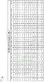
Fig. 7B shows an illustrative table 720 depicting an example construction of the unique RU sequence 701 of fig. 7A. An example construction of the unique RU sequence 701 is described below in the context of an 80MHz Wi-Fi network. It should be understood that the example construction of the unique RU sequence 701, or a derivation thereof, may also be applicable to wireless networks utilizing other frequency bandwidths, such as a 40MHz bandwidth.
Referring also to FIG. 4, the IEEE802.11 ax specification may specify that an 80MHz channel includes thirty-seven (37) 2MHz RUs. In some implementations, the AP may assign an initial count value of "0" to each of thirty-seven RUs (represented in fig. 7B as RUs 1-RU 37). An RU with a count value of "0" is available for one of the associated devices allocated to the AP for UL OFDMA transmissions during the next TXOP.
When the AP initially allocates RUs to the wireless device for UL OFDMA transmission, the AP may reset the count value of RUs to the maximum count value of "15". For each subsequent TXOP, the AP may select one of the RUs having a count value of "0" and may decrement the count value of all RUs previously allocated to the wireless device by a value of "1". This process of assigning a unique RU to a wireless device may continue until the wireless device has transmitted UL MU data on at least 15 different RUs (which may correspond to a sequence period for the wireless device). A similar process may be performed for each wireless device identified by the trigger frame for UL transmission. In this way, the AP may ensure that none of its wireless devices transmit UL data on the same RU for at least 15 TXOPs.
In some aspects, the maximum count value may be based on a number of consecutive channel hops that the wireless device may qualify as a frequency hopping device. Thus, in locations such as japan and europe, when an RU is initially allocated to a wireless device for ul ofdma transmission, the AP may reset its count value to a maximum count value of "15," e.g., because both japan and europe consider the wireless device as a frequency hopping device based at least in part on the wireless device hopping between 15 different channels (or RUs) within a given sequence period. For other locations, the maximum count value may be set to another suitable number depending, for example, on applicable government regulations qualifying the wireless device as a frequency hopping device.
For the example of fig. 7B, the AP allocates RU1 to STA1 during the first TXOP and resets the count value of RU1 to 15. For the second TXOP, the AP allocates RU2 to STA1, resets the count value of RU2 to 15, and decrements the count value of RU1 to 14. For the third TXOP, the AP allocates RU3 to STA1, resets the count value of RU3 to 15, decrements the count value of RU2 to 14, and decrements the count value of RU1 to 13. For the fourth TXOP, the AP allocates RU4 to STA1, resets the count value of RU4 to 15, decrements the count value of RU3 to 14, decrements the count value of RU2 to 13, and decrements the count value of RU1 to 12. This process may continue until the AP has allocated 15 different RUs to STA1, e.g., during a sequence period spanning 15 RUs. Thus, for the fifteenth TXOP, the AP may allocate RU15 to STA1, reset its count value to 15, and decrement each of the count values of the previously allocated resource units RU1-RU14 by 1, e.g., as depicted in table 720 of fig. 7B.
The AP may construct unique RU sequences for other wireless devices in a similar manner, e.g., by staggering allocation of RUs in a manner that prevents the same RU from being used by more than one wireless device in a given TXOP. For example, the AP may use the example table 720 to construct the unique RU sequences 702-704 for the respective stations STA2-STA4 of fig. 7A.
In other implementations, the AP may use a negative number (rather than a positive number) to determine when a previously used RU may be available again for allocation to the wireless device. For example, when an AP allocates an RU to a wireless device during a TXOP, the AP may reset the count value of the RU to a minimum weight value of "-15" (or other number based on the number of successive channel hops that qualify the wireless device as a frequency hopping device). Subsequently, the AP may increment the count value of the previously allocated RU by "1" (such as to a more positive number) during each subsequent TXOP. When the count value of a given RU has increased to its initial count value of "0," the given RU may be allocated by the AP to one of its wireless devices again for UL OFDMA transmission.
Fig. 8 shows an example trigger frame 800. The trigger frame 800 may be used as the trigger frame 610 of fig. 6A or as the trigger frame 620 of fig. 6B. The trigger frame 800 is shown to include a frame control field 801, a duration field 802, a Receiver Address (RA) field 803, a Transmitter Address (TA) field 804, a common information field 805, a number of per-user information fields 806(1) -806(n), and a Frame Check Sequence (FCS) field 807.
The frame control field 801 includes a type field 821A and a subtype field 801B. The type field 801A may store a value indicating that the trigger frame 800 is a control frame, and the subtype field 801B may store a value indicating the type of the trigger frame 800. The duration field 802 may store information indicating the duration or length of the trigger frame 800. The RA field 803 may store an address of a recipient device, such as one of the wireless stations STA1-STA4 of fig. 6A and 6B. TA field 804 may store the address of the transmitting device (such as the AP of fig. 6A and 6B). Common information field 805 may store information common to one or more recipient devices. Each of the per-user information fields 806(1) -806(n) may store information about a particular recipient device, as described in more detail below with reference to fig. 9B. The FCS field 807 may store a frame check sequence (such as for error detection). In some implementations, the common information field 805 may store a hopping schedule. In other implementations, the hopping schedule may be stored in an Information Element (IE) or vendor specific information element (vsee) included within or appended to the trigger frame 800 (the IE and the vsee are not shown for simplicity). In some other implementations, the hopping schedule may be stored in a packet extension appended to the trigger frame 800 (the packet extension is not shown for simplicity).
Fig. 9A shows an example common information field 900. The common information field 900 may be one implementation of the common information field 805 of the trigger frame 800 of fig. 8. The common information field 900 is shown to include a length subfield 901, a concatenation indication subfield 902, a high efficiency signaling a (HE-SIG-a) information subfield 903, a Cyclic Prefix (CP) and Legacy Training Field (LTF) type subfield 904, a trigger type subfield 905, and a trigger-dependent common information subfield 906. The length subfield 901 may indicate the length of a legacy signaling field of an UL data frame to be transmitted in response to the trigger frame 800. The concatenation indication subfield 902 may indicate whether a subsequent trigger frame follows the current trigger frame. For example, the concatenation indication subfield 902 of the trigger frame 611 of fig. 6B may indicate that the trigger frame 621 is to follow the trigger frame 611.
The HE-SIG-a information subfield 903 may indicate the contents of the HE-SIG-a field of the UL data frame to be transmitted in response to the trigger frame 800. The CP and LTF type subfield 904 may indicate a cyclic prefix and an HE-LTF type of the UL data frame to be transmitted in response to the trigger frame 600. The trigger type subfield 905 may indicate the type of trigger frame. The trigger dependent common information subfield 906 may indicate trigger dependent information. In some aspects, the common information subfield 906 depending on the trigger may store a frequency hopping schedule.
Fig. 9B shows an example per-user information field 910. The per-user information field 910 may be one implementation of the per-user information fields 806(1) -806(n) of the trigger frame 800 of fig. 8. The per-user information field 910 is shown to include a user identifier subfield 911, an RU allocation subfield 912, an encoding type subfield 913, an MCS subfield 914, a Dual Carrier Modulation (DCM) subfield 915, a Spatial Stream (SS) allocation subfield 916, and a per-user message depending on triggering subfield 917. The user identifier subfield 911 may indicate an Association Identification (AID) of the STA to which a dedicated RU is allocated for transmitting UL MU data. The RU allocation subfield 912 can identify a dedicated RU allocated to the corresponding STA, such as the STA identified by the user identifier subfield 911. The encoding type subfield 913 may indicate an encoding type used by the corresponding STA when transmitting UL data using the allocated RU. The MCS subfield 914 may indicate an MCS used by the corresponding STA when transmitting UL data using the allocated RU. DCM subfield 915 may indicate the dual carrier modulation used by the corresponding STA when transmitting UL data using the allocated RU. The SS allocation subfield 916 may indicate the number of spatial streams used by the corresponding STA when transmitting UL data using the allocated RUs.
The per user information depending on trigger subfield 917 may store information about the STA identified by the user identifier subfield 911 depending on the trigger frame type. For example, if the trigger frame is a multi-user block acknowledgement request (MU-BAR) frame, the per-user information subfield 917 depending on the trigger may store BAR control parameters and BAR information. In some aspects, the per user information subfield 917 depending on the trigger may store a frequency hopping pattern for the corresponding STA.
Fig. 10 shows an illustrative flow diagram depicting example operations 1000 for qualifying a wireless device as a frequency hopping device. Although example operation 1000 is described below in the context of an AP allocating resource units to wireless devices, it should be understood that any suitable wireless device may perform operation 1000 of fig. 10. For some implementations, the wireless device may be one of stations STA1-STA4 of fig. 1 or an example of STA200 of fig. 2, and the AP may be an example of AP110 of fig. 1 or AP 300 of fig. 3.
The AP may determine a frequency hopping pattern for the wireless device (1002). In some implementations, the frequency hopping pattern can be based on government regulations indicating eligibility to be considered a frequency hopping device. In some aspects, the frequency hopping pattern may instruct the wireless device to hop between 15 or more unique frequency bands during a time period. The frequency hopping pattern may also indicate a maximum dwell time on each unique frequency band, or may indicate that the cumulative dwell time in the unique frequency bands will be no more than a time period greater than the duration of the frequency hopping sequence.
The AP may announce a frequency hopping pattern to the wireless device (1004). In some implementations, the AP may announce the frequency hopping pattern in a beacon frame. The beacon frame may also include a frequency hopping schedule for a number of wireless devices associated with the AP. In some aspects, the frequency hopping schedule may include or be formed by a frequency hopping pattern of a number of wireless devices associated with the AP. In other implementations, the AP may announce the frequency hopping pattern in a trigger frame. The trigger frame may also include a frequency hopping schedule for a plurality of wireless devices associated with the AP.
The AP may assign a unique sequence of resource elements to the wireless device based on the frequency hopping pattern (1006). For example, each of the unique resource units includes a different set of frequency subcarriers so that multiple wireless devices may transmit uplink data simultaneously. In some aspects, each of the unique resource units may be associated with a corresponding one of a series of transmit opportunities (TXOPs).
In some implementations, the trigger frame can assign a unique sequence of resource units to the wireless device (1006A). The trigger frame may contain an indication that the wireless device is to successively hop between more than a specified number of unique resource units. Additionally or alternatively, the trigger frame may contain one of: an indication that the wireless device is to dwell on each of the unique resource units for less than a duration, and an indication that the cumulative dwell time in the unique resource units will be no more than a period of time greater than the duration of the sequence of unique resource units. In some aspects, the dwell time is 400 milliseconds, the time period is 15 milliseconds, and the sequence includes at least 15 unique resource units.
In other implementations, each trigger frame may allocate resource units to the wireless device for a corresponding TXOP, e.g., as described above with reference to fig. 6B.
The AP may receive a series of uplink Orthogonal Frequency Division Multiple Access (OFDMA) transmissions from the wireless device over the allocated sequence of unique resource units during the sequence period (1008). Because the wireless device switches or "hops" between different resource units when transmitting a series of OFDMA transmissions to the AP in a manner consistent with a frequency hopping device, the wireless device may qualify as a frequency hopping device and transmit signals at a higher power level associated with the frequency hopping device. In this way, aspects of the present disclosure may increase the range of a wireless device.
Fig. 11 shows an illustrative flow diagram depicting example operations 1100 for allocating resource units to a wireless device. Although example operations 1100 are described below in the context of an AP allocating resource units to wireless devices, it should be understood that any suitable wireless device may perform operations 1100 of fig. 11. For some implementations, the wireless device may be an example of station STA1-STA4 of fig. 1 or STA200 of fig. 2, and the AP may be an example of AP110 of fig. 1 or AP 300 of fig. 3.
The AP may assign a count value equal to zero to each of the plurality of resource units (1102). For example, referring also to fig. 7B, the AP may assign an initial count value of "0" for each of resource units RU1-RU 37. A Resource Unit (RU) having a count value of "0" is available for one of the associated devices allocated to the AP for UL OFDMA transmission during the next TXOP.
The AP may allocate a first resource unit of the plurality of resource units to the wireless device for a first transmit opportunity (TXOP) (1104), and then reset a count value of the first resource unit to a maximum value based on its allocation to the wireless device (1106). In some implementations, the maximum count value may be "15," e.g., because both japan and europe consider a wireless device to be a frequency hopping device based at least in part on the wireless device hopping between 15 different channels (or RUs) within a given sequence period.
The AP may decrement the count value of the first resource unit by 1(1108) during the next TXOP. In an implementation with a maximum count value of "15", the AP may decrement the count value of the first resource unit by 1 to "14". The process may continue until the wireless device has transmitted UL MU data on at least 15 different RUs, after which the count value of the first resource unit will return to zero. Thereafter, the AP may again allocate the first resource unit to the wireless device.
Fig. 12 shows an illustrative flow diagram depicting example operations 1200 for a wireless station to transmit data using resource units allocated based on frequency hopping scheduling. For some implementations, the wireless station may be one of stations STA1-STA4 of fig. 1 or an example of STA200 of fig. 2.
The wireless station may receive a frequency hopping pattern (1202), and may receive an allocation of a sequence of unique resource units based on the frequency hopping pattern, each of the unique resource units comprising a different set of frequency subcarriers (1204). The frequency hopping pattern may be based on government regulations indicating eligibility for the wireless station to be considered a frequency hopping device. In some aspects, the frequency hopping pattern may instruct the wireless station to hop between 15 or more unique frequency bands during a time period. The frequency hopping pattern may also indicate a maximum dwell time on each unique frequency band, or may indicate that the cumulative dwell time in the unique frequency bands will be no more than a time period greater than the duration of the frequency hopping sequence.
In some implementations, a wireless station may receive a trigger frame from an Access Point (AP) that allocates a sequence of unique resource elements to the wireless station and indicates that the wireless station is to successively frequency hop among more than a specified number of unique resource elements. In some aspects, the trigger frame may also include a frequency hopping pattern. In other aspects, the frequency hopping pattern can be broadcast in a beacon frame.
Additionally or alternatively, the trigger frame may contain one of: an indication that the wireless station is to dwell on each of the unique resource units for less than a duration, and an indication that a cumulative dwell time in the unique resource units will be no more than a period of time greater than the duration of the sequence of unique resource units. In some aspects, the dwell time is 400 milliseconds, the time period is 15 milliseconds, and the sequence includes at least 15 unique resource units.
The wireless station may transmit a series of Orthogonal Frequency Division Multiple Access (OFDMA) data transmissions over the allocated sequence of unique resource units during a sequence period (1206). For example, each of the unique resource units may include a different set of frequency subcarriers so that multiple wireless stations may transmit uplink data simultaneously. In some aspects, each of the unique resource units may be associated with a corresponding one of a series of transmit opportunities (TXOPs). Because the wireless station switches or "hops" between different resource units when sending a series of OFDMA data transmissions in a manner consistent with a frequency hopping device, such as to an AP, the wireless station may qualify as a frequency hopping device and transmit signals at a higher power level associated with the frequency hopping device. In this way, aspects of the present disclosure may increase the range of a wireless station.
As used herein, a phrase referring to "at least one of a list of items" refers to any combination of these items, including a single member. By way of example, "at least one of a, b, or c" is intended to encompass: a. b, c, a-b, a-c, b-c, and a-b-c.
The various illustrative logics, logical blocks, modules, circuits, and algorithm processes described in connection with the implementations disclosed herein may be implemented as electronic hardware, computer software, or combinations of both. This interchangeability of hardware and software has been described generally, in terms of its functionality, and is illustrated in the various illustrative components, blocks, modules, circuits, and processes described above. Whether such functionality is implemented as hardware or software depends upon the particular application and design constraints imposed on the overall system.
The hardware and data processing apparatus used to implement the various illustrative logics, logical blocks, modules, and circuits described in connection with the aspects disclosed herein may be implemented or performed with a general purpose single-or multi-chip processor, a Digital Signal Processor (DSP), an Application Specific Integrated Circuit (ASIC), a Field Programmable Gate Array (FPGA) or other programmable logic device, discrete gate or transistor logic, discrete hardware components, or any combination thereof designed to perform the functions described herein. A general purpose processor may be a microprocessor, or any conventional processor, controller, microcontroller, or state machine. A processor may also be implemented as a combination of computing devices, such as, for example, a combination of a DSP and a microprocessor, a plurality of microprocessors, one or more microprocessors in conjunction with a DSP core, or any other such configuration. In some implementations, certain processes and methods may be performed by circuitry that is dedicated to a given function.
In one or more aspects, the functions described may be implemented in hardware, digital electronic circuitry, computer software, firmware, including the structures disclosed in this specification and their structural equivalents, or any combination thereof. Implementations of the subject matter described in this specification can also be implemented as one or more computer programs, i.e., one or more modules of computer program instructions, encoded on a computer storage medium for execution by, or to control the operation of, data processing apparatus.
If implemented in software, the functions may be stored on or transmitted over as one or more instructions or code on a computer-readable medium. The processes of the methods or algorithms disclosed herein may be implemented in processor-executable software modules, which may reside on computer-readable media. Computer-readable media includes both computer storage media and communication media, including any medium that can be implemented to transfer a computer program from one place to another. A storage media may be any available media that can be accessed by a computer. By way of example, and not limitation, such computer-readable media can comprise RAM, ROM, EEPROM, CD-ROM or other optical disk storage, magnetic disk storage or other magnetic storage devices, or any other medium that can be used to store desired program code in the form of instructions or data structures and that can be accessed by a computer. Any connection is properly termed a computer-readable medium. Disk (disk) and disc (disc), as used herein, includes Compact Disc (CD), laser disc, optical disc, Digital Versatile Disc (DVD), floppy disk and blu-ray disc where disks (disks) usually reproduce data magnetically, while discs (discs) reproduce data optically with lasers. Combinations of the above should also be included within the scope of computer-readable media. Additionally, the operations of a method or algorithm may reside as one or any combination or set of codes and instructions on a machine readable medium and computer readable medium, which may be incorporated into a computer program product.
Various modifications to the implementations described in this disclosure may be readily apparent to those skilled in the art, and the generic principles defined herein may be applied to other implementations without departing from the spirit or scope of the disclosure. Thus, the claims are not intended to be limited to the implementations shown herein but are to be accorded the widest scope consistent with the present disclosure, the principles and novel features disclosed herein.
Claims (23)
1. A method for qualifying a wireless device compatible with one or more IEEE802.11 standards as a frequency hopping device, comprising:
determining a frequency hopping pattern that is unique to the wireless device that is compatible with applicable power spectral density constraints imposed on the frequency hopping device;
allocating a unique sequence of resource units to the wireless device based on a unique frequency hopping pattern, each of the resource units in the unique sequence comprising a different set of frequency subcarriers;
transmitting a trigger frame to the wireless device, the trigger frame allocating the unique sequence of resource units to the wireless device and instructing the wireless device to successively frequency hop across the resource units in the unique sequence based on the unique frequency hopping pattern, wherein the unique frequency hopping pattern is included in at least one of: a common information field of the trigger frame or an Information Element (IE) appended to the trigger frame; and
during a sequence period, receiving a series of uplink Orthogonal Frequency Division Multiple Access (OFDMA) transmissions from the wireless device over the unique sequence of resource units, wherein each of the resource units in the unique sequence is associated with a corresponding one of a series of transmit opportunities (TXOPs), and wherein the resource units associated with a respective one of the TXOPs are not allocated to another wireless device during the respective TXOP.
2. The method of claim 1, wherein the trigger frame instructs the wireless device to frequency hop across the resource elements in the unique sequence for at least the sequence period.
3. The method of claim 1, wherein the trigger frame comprises one of: an indication that the wireless device is to dwell on each of the resource units in the unique sequence for less than a duration, and an indication that a cumulative dwell time in each of the resource units in the unique sequence will be no more than a period of time greater than a duration of the unique sequence of resource units.
4. The method of claim 3, wherein the dwell time is 400 milliseconds, the time period is 15 milliseconds, and the unique sequence includes at least 15 different resource units.
5. The method of claim 1, wherein the trigger frame contains a frequency hopping schedule indicating a unique frequency hopping pattern for a plurality of wireless devices to concurrently transmit uplink data using OFDMA communications.
6. The method of claim 1, wherein the allocating comprises:
assigning a count value initialized to zero to each of the plurality of resource units;
allocating a first resource unit of the plurality of resource units to the wireless device for a first transmit opportunity (TXOP) if the count value assigned to the first resource unit is equal to zero;
resetting the count value assigned to the first resource unit to a maximum value after allocation of the first resource unit to the wireless device, wherein the maximum value is an integer greater than two;
decrementing the count value assigned to the first resource unit by 1 for each of a number of subsequent TXOPs; and
refraining from allocating the first resource unit to the wireless device until the assigned count value of the first resource unit is equal to zero.
7. The method of claim 6, wherein a maximum value of the count value is based on a number of consecutive frequency hops associated with qualifying the wireless device as a frequency hopping device.
8. An Access Point (AP), comprising:
one or more processors; and
memory storing instructions that, when executed by the one or more processors, cause the AP to qualify wireless devices compatible with one or more IEEE802.11 standards as frequency hopping devices by:
determining a frequency hopping pattern that is unique to the wireless device that is compatible with applicable power spectral density constraints imposed on the frequency hopping device;
allocating a unique sequence of resource units to the wireless device based on a unique frequency hopping pattern, each of the resource units in the unique sequence comprising a different set of frequency subcarriers;
transmitting a trigger frame to the wireless device, the trigger frame allocating the unique sequence of resource units to the wireless device and instructing the wireless device to successively frequency hop across the resource units in the unique sequence based on the unique frequency hopping pattern, wherein the unique frequency hopping pattern is included in at least one of: a common information field of the trigger frame or an Information Element (IE) appended to the trigger frame; and
during a sequence period, receiving a series of uplink Orthogonal Frequency Division Multiple Access (OFDMA) transmissions from the wireless device over the unique sequence of resource units, wherein each of the resource units in the unique sequence is associated with a corresponding one of a series of transmit opportunities (TXOPs), and wherein the resource units associated with a respective one of the TXOPs are not allocated to another wireless device during the respective TXOP.
9. The AP of claim 8, wherein the trigger frame instructs the wireless device to frequency hop across the resource elements in the unique sequence for at least the sequence period.
10. The AP of claim 8, wherein the trigger frame comprises one of: an indication that the wireless device is to dwell on each of the resource units in the unique sequence for less than a duration, and an indication that a cumulative dwell time in each of the resource units in the unique sequence will be no more than a period of time greater than a duration of the unique sequence of resource units.
11. The AP of claim 10, wherein the dwell time is 400 milliseconds, the time period is 15 milliseconds, and the unique sequence includes at least 15 different resource units.
12. The AP of claim 8, wherein the trigger frame contains a frequency hopping schedule indicating a unique frequency hopping pattern for a plurality of wireless devices to concurrently transmit uplink data using OFDMA communication.
13. The AP of claim 8, wherein execution of the instructions to allocate the sequence of unique resource units causes the AP to:
assigning a count value initialized to zero to each of the plurality of resource units;
allocating a first resource unit of the plurality of resource units to the wireless device for a first transmit opportunity (TXOP) if the count value assigned to the first resource unit is equal to zero;
resetting the count value assigned to the first resource unit to a maximum value after allocation of the first resource unit to the wireless device, wherein the maximum value is an integer greater than two;
decrementing the count value assigned to the first resource unit by 1 for each of a number of subsequent TXOPs; and
refraining from allocating the first resource unit to the wireless device until the assigned count value of the first resource unit is equal to zero.
14. A non-transitory computer-readable medium comprising instructions that, when executed by one or more processors of an Access Point (AP), cause the AP to qualify wireless devices compliant with one or more IEEE802.11 standards as frequency hopping devices by performing operations comprising:
determining a frequency hopping pattern that is unique to the wireless device that is compatible with applicable power spectral density constraints imposed on the frequency hopping device;
allocating a unique sequence of resource units to the wireless device based on a unique frequency hopping pattern, each of the resource units in the unique sequence comprising a different set of frequency subcarriers;
transmitting a trigger frame to the wireless device, the trigger frame allocating the unique sequence of resource units to the wireless device and instructing the wireless device to successively frequency hop across the resource units in the unique sequence based on the unique frequency hopping pattern, wherein the unique frequency hopping pattern is included in at least one of: a common information field of the trigger frame or an Information Element (IE) appended to the trigger frame; and
during a sequence period, receiving a series of uplink Orthogonal Frequency Division Multiple Access (OFDMA) transmissions from the wireless device over the unique sequence of resource units, wherein each of the resource units in the unique sequence is associated with a corresponding one of a series of transmit opportunities (TXOPs), and wherein the resource units associated with a respective one of the TXOPs are not allocated to another wireless device during the respective TXOP.
15. The non-transitory computer-readable medium of claim 14, wherein the trigger frame instructs the wireless device to frequency hop across the resource units in the unique sequence for at least the sequence period.
16. The non-transitory computer-readable medium of claim 14, wherein the trigger frame includes one of: an indication that the wireless device is to dwell on each of the resource units in the unique sequence for less than a duration, and an indication that a cumulative dwell time in each of the resource units in the unique sequence will be no more than a period of time greater than a duration of the unique sequence of resource units.
17. The non-transitory computer-readable medium of claim 16, in which the dwell time is 400 milliseconds, the time period is 15 milliseconds, and the unique sequence includes at least 15 different resource units.
18. The non-transitory computer-readable medium of claim 14, wherein the trigger frame contains a frequency hopping schedule indicating a unique frequency hopping pattern for a plurality of wireless devices to concurrently transmit uplink data using OFDMA communications.
19. The non-transitory computer-readable medium of claim 14, wherein execution of the instructions to allocate the sequence of unique resource units causes the AP to perform operations further comprising:
assigning a count value initialized to zero to each of the plurality of resource units;
allocating a first resource unit of the plurality of resource units to the wireless device for a first transmit opportunity (TXOP) if the count value assigned to the first resource unit is equal to zero;
resetting the count value assigned to the first resource unit to a maximum value after allocation of the first resource unit to the wireless device, wherein the maximum value is an integer greater than two; and
decrementing the count value assigned to the first resource unit by 1 for each of a number of subsequent TXOPs; and
refraining from allocating the first resource unit to the wireless device until the assigned count value of the first resource unit is equal to zero.
20. A wireless station compatible with one or more IEEE802.11 standards, the wireless station comprising:
one or more processors; and
memory storing instructions that, when executed by the one or more processors, qualify the wireless station as a frequency hopping device by:
receiving a frequency hopping pattern unique to the wireless station that is compatible with applicable power spectral density constraints imposed on a frequency hopping apparatus;
receiving an allocation of a unique sequence of resource units based on a unique frequency hopping pattern, each of the resource units in the unique sequence comprising a different set of frequency subcarriers;
receiving a trigger frame that allocates the unique sequence of resource units to the wireless station and instructs the wireless station to successively hop across the resource units in the unique sequence based on the unique hopping pattern, wherein the unique hopping pattern is included in at least one of: a common information field of the trigger frame or an Information Element (IE) appended to the trigger frame; and
transmitting a series of Orthogonal Frequency Division Multiple Access (OFDMA) data transmissions over the unique sequence of resource units during a sequence period, wherein each of the resource units in the unique sequence is associated with a corresponding one of a series of transmit opportunities (TXOP), and wherein the resource units associated with a respective one of the TXOP are not allocated to another wireless device during the respective TXOP.
21. The wireless station of claim 20, wherein the trigger frame comprises one of: an indication that the wireless station is to dwell on each of the resource units in the unique sequence for less than a duration, and an indication that a cumulative dwell time in each of the resource units in the unique sequence will be no more than a period of time greater than a duration of the unique sequence of resource units.
22. The wireless station of claim 21, wherein the dwell time is 400 milliseconds, the time period is 15 milliseconds, and the unique sequence includes at least 15 different resource units.
23. The wireless station of claim 20, wherein the trigger frame contains a frequency hopping schedule indicating a unique frequency hopping pattern for a plurality of wireless devices to concurrently transmit uplink data using OFDMA communications.
Applications Claiming Priority (5)
| Application Number | Priority Date | Filing Date | Title |
|---|---|---|---|
| US201662321930P | 2016-04-13 | 2016-04-13 | |
| US62/321,930 | 2016-04-13 | ||
| US15/486,083 US10356777B2 (en) | 2016-04-13 | 2017-04-12 | Frequency hopping in OFDMA wireless networks |
| US15/486,083 | 2017-04-12 | ||
| PCT/US2017/027376 WO2017180845A1 (en) | 2016-04-13 | 2017-04-13 | Frequency hopping in ofdma wireless networks |
Publications (2)
| Publication Number | Publication Date |
|---|---|
| CN109075812A CN109075812A (en) | 2018-12-21 |
| CN109075812B true CN109075812B (en) | 2020-08-14 |
Family
ID=60039170
Family Applications (1)
| Application Number | Title | Priority Date | Filing Date |
|---|---|---|---|
| CN201780023014.7A Active CN109075812B (en) | 2016-04-13 | 2017-04-13 | Frequency hopping in OFDMA wireless networks |
Country Status (9)
| Country | Link |
|---|---|
| US (1) | US10356777B2 (en) |
| EP (1) | EP3443681B1 (en) |
| JP (1) | JP6640379B2 (en) |
| KR (1) | KR102103185B1 (en) |
| CN (1) | CN109075812B (en) |
| BR (1) | BR112018070888A2 (en) |
| CA (1) | CA3017629C (en) |
| TW (1) | TW201737635A (en) |
| WO (1) | WO2017180845A1 (en) |
Families Citing this family (11)
| Publication number | Priority date | Publication date | Assignee | Title |
|---|---|---|---|---|
| CN108633033B (en) * | 2017-03-24 | 2023-05-12 | 中兴通讯股份有限公司 | Transmission resource determining method, device and user equipment |
| US10485001B2 (en) * | 2017-08-17 | 2019-11-19 | Mediatek Singapore Pte. Ltd. | Frequency hopping design for grant-free transmission in mobile communications |
| KR102362899B1 (en) * | 2017-10-31 | 2022-02-11 | 삼성에스디에스 주식회사 | Conference system and method for controlling bandwidth thereof |
| US10879954B2 (en) * | 2017-11-14 | 2020-12-29 | Qualcomm Incorporated | Logical channel hopping sequence design |
| CN108366385B (en) * | 2018-02-07 | 2022-04-01 | 成都泰格微电子研究所有限责任公司 | Synchronous frequency hopping orthogonal networking method based on frequency point grouping |
| CN113748739A (en) * | 2019-05-06 | 2021-12-03 | 索尼集团公司 | Communication apparatus and method |
| US11632766B2 (en) | 2019-06-17 | 2023-04-18 | Cypress Semiconductor Corporation | Devices, systems and methods for dynamically allocating portions of channels to different communication protocols |
| US20210289500A1 (en) * | 2020-03-13 | 2021-09-16 | Qualcomm Incorporated | Physical layer (phy) packet design for power spectral density (psd) limits |
| US11888770B2 (en) | 2020-03-13 | 2024-01-30 | Qualcomm Incorporated | Wireless transmissions using distributed tones |
| US11736232B2 (en) * | 2020-09-21 | 2023-08-22 | Telefonaktiebolaget Lm Ericsson (Publ) | Code block size |
| US11622379B2 (en) * | 2021-02-10 | 2023-04-04 | Hewlett Packard Enterprise Development Lp | Enhancing triggered single user transmissions in WLAN networks |
Family Cites Families (8)
| Publication number | Priority date | Publication date | Assignee | Title |
|---|---|---|---|---|
| US9036538B2 (en) * | 2005-04-19 | 2015-05-19 | Qualcomm Incorporated | Frequency hopping design for single carrier FDMA systems |
| US10084627B2 (en) * | 2006-07-10 | 2018-09-25 | Qualcomm Incorporated | Frequency hopping in an SC-FDMA environment |
| GB2446197A (en) * | 2007-02-05 | 2008-08-06 | Nec Corp | Frequency-hopping method and mobile communication system |
| EP2115917A4 (en) * | 2007-02-23 | 2015-03-25 | Ericsson Telefon Ab L M | Frequency hopping scheme for ofdma system |
| CN102726093B (en) * | 2010-02-02 | 2016-08-03 | 马维尔国际贸易有限公司 | Power saving feature in communication equipment |
| CN103875187B (en) * | 2011-06-02 | 2016-01-06 | 美国博通公司 | Exempting to authorize/share the frequency hopping in frequency band |
| US9408214B2 (en) | 2014-07-24 | 2016-08-02 | Qualcomm Incorporated | Methods and systems for protection and bandwidth selection for downlink and uplink frequency division multiple access communications |
| KR20160045023A (en) * | 2014-10-16 | 2016-04-26 | 뉴라컴 인코포레이티드 | Method and apparatus for uplink channel access in a high efficiency wireless lan |
-
2017
- 2017-04-12 US US15/486,083 patent/US10356777B2/en active Active
- 2017-04-13 CA CA3017629A patent/CA3017629C/en active Active
- 2017-04-13 CN CN201780023014.7A patent/CN109075812B/en active Active
- 2017-04-13 EP EP17720345.2A patent/EP3443681B1/en active Active
- 2017-04-13 BR BR112018070888A patent/BR112018070888A2/en unknown
- 2017-04-13 TW TW106112440A patent/TW201737635A/en unknown
- 2017-04-13 JP JP2018553468A patent/JP6640379B2/en active Active
- 2017-04-13 KR KR1020187029231A patent/KR102103185B1/en active IP Right Grant
- 2017-04-13 WO PCT/US2017/027376 patent/WO2017180845A1/en active Application Filing
Also Published As
| Publication number | Publication date |
|---|---|
| US10356777B2 (en) | 2019-07-16 |
| JP6640379B2 (en) | 2020-02-05 |
| CA3017629C (en) | 2021-03-23 |
| CA3017629A1 (en) | 2017-10-19 |
| EP3443681B1 (en) | 2023-03-08 |
| JP2019516303A (en) | 2019-06-13 |
| US20170303275A1 (en) | 2017-10-19 |
| CN109075812A (en) | 2018-12-21 |
| TW201737635A (en) | 2017-10-16 |
| KR20180132681A (en) | 2018-12-12 |
| EP3443681A1 (en) | 2019-02-20 |
| KR102103185B1 (en) | 2020-04-22 |
| BR112018070888A2 (en) | 2019-02-05 |
| WO2017180845A1 (en) | 2017-10-19 |
Similar Documents
| Publication | Publication Date | Title |
|---|---|---|
| US11405953B2 (en) | Trigger-based random access in a multiple BSSID network | |
| CN109075812B (en) | Frequency hopping in OFDMA wireless networks | |
| US11696338B2 (en) | Random access resource unit allocation for a multiple BSSID network | |
| CN109076531B (en) | Random access resource unit allocation for multiple BSSID networks | |
| EP3841818B1 (en) | Random access resource unit allocation for a multiple bssid network |
Legal Events
| Date | Code | Title | Description |
|---|---|---|---|
| PB01 | Publication | ||
| PB01 | Publication | ||
| SE01 | Entry into force of request for substantive examination | ||
| SE01 | Entry into force of request for substantive examination | ||
| GR01 | Patent grant | ||
| GR01 | Patent grant |