CN109072827B - Flat air filter element and air filter - Google Patents
Flat air filter element and air filter Download PDFInfo
- Publication number
- CN109072827B CN109072827B CN201780026185.5A CN201780026185A CN109072827B CN 109072827 B CN109072827 B CN 109072827B CN 201780026185 A CN201780026185 A CN 201780026185A CN 109072827 B CN109072827 B CN 109072827B
- Authority
- CN
- China
- Prior art keywords
- air filter
- housing
- recess
- flat air
- filter element
- Prior art date
- Legal status (The legal status is an assumption and is not a legal conclusion. Google has not performed a legal analysis and makes no representation as to the accuracy of the status listed.)
- Active
Links
Images


Classifications
-
- F—MECHANICAL ENGINEERING; LIGHTING; HEATING; WEAPONS; BLASTING
- F02—COMBUSTION ENGINES; HOT-GAS OR COMBUSTION-PRODUCT ENGINE PLANTS
- F02M—SUPPLYING COMBUSTION ENGINES IN GENERAL WITH COMBUSTIBLE MIXTURES OR CONSTITUENTS THEREOF
- F02M35/00—Combustion-air cleaners, air intakes, intake silencers, or induction systems specially adapted for, or arranged on, internal-combustion engines
- F02M35/02—Air cleaners
- F02M35/024—Air cleaners using filters, e.g. moistened
- F02M35/02475—Air cleaners using filters, e.g. moistened characterised by the shape of the filter element
- F02M35/02491—Flat filter elements, e.g. rectangular
-
- B—PERFORMING OPERATIONS; TRANSPORTING
- B01—PHYSICAL OR CHEMICAL PROCESSES OR APPARATUS IN GENERAL
- B01D—SEPARATION
- B01D46/00—Filters or filtering processes specially modified for separating dispersed particles from gases or vapours
- B01D46/0002—Casings; Housings; Frame constructions
- B01D46/0005—Mounting of filtering elements within casings, housings or frames
-
- B—PERFORMING OPERATIONS; TRANSPORTING
- B01—PHYSICAL OR CHEMICAL PROCESSES OR APPARATUS IN GENERAL
- B01D—SEPARATION
- B01D46/00—Filters or filtering processes specially modified for separating dispersed particles from gases or vapours
- B01D46/10—Particle separators, e.g. dust precipitators, using filter plates, sheets or pads having plane surfaces
-
- B—PERFORMING OPERATIONS; TRANSPORTING
- B01—PHYSICAL OR CHEMICAL PROCESSES OR APPARATUS IN GENERAL
- B01D—SEPARATION
- B01D46/00—Filters or filtering processes specially modified for separating dispersed particles from gases or vapours
- B01D46/42—Auxiliary equipment or operation thereof
- B01D46/4236—Reducing noise or vibration emissions
-
- F—MECHANICAL ENGINEERING; LIGHTING; HEATING; WEAPONS; BLASTING
- F02—COMBUSTION ENGINES; HOT-GAS OR COMBUSTION-PRODUCT ENGINE PLANTS
- F02M—SUPPLYING COMBUSTION ENGINES IN GENERAL WITH COMBUSTIBLE MIXTURES OR CONSTITUENTS THEREOF
- F02M35/00—Combustion-air cleaners, air intakes, intake silencers, or induction systems specially adapted for, or arranged on, internal-combustion engines
- F02M35/02—Air cleaners
- F02M35/0201—Housings; Casings; Frame constructions; Lids; Manufacturing or assembling thereof
- F02M35/0202—Manufacturing or assembling; Materials for air cleaner housings
- F02M35/0203—Manufacturing or assembling; Materials for air cleaner housings by using clamps, catches, locks or the like, e.g. for disposable plug-in filter cartridges
-
- F—MECHANICAL ENGINEERING; LIGHTING; HEATING; WEAPONS; BLASTING
- F02—COMBUSTION ENGINES; HOT-GAS OR COMBUSTION-PRODUCT ENGINE PLANTS
- F02M—SUPPLYING COMBUSTION ENGINES IN GENERAL WITH COMBUSTIBLE MIXTURES OR CONSTITUENTS THEREOF
- F02M35/00—Combustion-air cleaners, air intakes, intake silencers, or induction systems specially adapted for, or arranged on, internal-combustion engines
- F02M35/02—Air cleaners
- F02M35/024—Air cleaners using filters, e.g. moistened
- F02M35/02441—Materials or structure of filter elements, e.g. foams
-
- B—PERFORMING OPERATIONS; TRANSPORTING
- B01—PHYSICAL OR CHEMICAL PROCESSES OR APPARATUS IN GENERAL
- B01D—SEPARATION
- B01D2271/00—Sealings for filters specially adapted for separating dispersed particles from gases or vapours
- B01D2271/02—Gaskets, sealings
-
- B—PERFORMING OPERATIONS; TRANSPORTING
- B01—PHYSICAL OR CHEMICAL PROCESSES OR APPARATUS IN GENERAL
- B01D—SEPARATION
- B01D2275/00—Filter media structures for filters specially adapted for separating dispersed particles from gases or vapours
- B01D2275/20—Shape of filtering material
- B01D2275/206—Special forms, e.g. adapted to a certain housing
-
- B—PERFORMING OPERATIONS; TRANSPORTING
- B01—PHYSICAL OR CHEMICAL PROCESSES OR APPARATUS IN GENERAL
- B01D—SEPARATION
- B01D2279/00—Filters adapted for separating dispersed particles from gases or vapours specially modified for specific uses
- B01D2279/60—Filters adapted for separating dispersed particles from gases or vapours specially modified for specific uses for the intake of internal combustion engines or turbines
Abstract
The invention relates to a flat air filter element (14), in particular for an air filter (10) in the intake tract of an internal combustion engine, having a filter medium (24) made of cellulose material, which carries a circumferential sealing element (26), wherein the sealing element (26) and the filter medium (24) have at least one recess (32) on the outer contour (26) of the flat air filter element (14), and wherein a circumferential retaining groove (48) is formed on the sealing element (26) for engaging a housing part (16, 18) of a filter housing (12). The invention also relates to an air filter (10) having a flat air filter element (12) according to the invention. The flat air filter element (14) according to the invention makes it possible to place as large a filter area as possible in a filter housing (12) of a predetermined shape and size. The air filter (10) according to the invention has a low pressure loss and a high acoustic damping characteristic without having to increase the installation space of the air filter (10).
Description
Technical Field
The invention relates to a flat air filter element, in particular for an air filter in the intake tract of an internal combustion engine, and to an air filter.
Background
Air filters are used in the intake tract of internal combustion engines, for example in motor vehicles, in order to clean pollutants from the combustion air supplied to the internal combustion engine. During the passage of the combustion air through the filter medium of the air filter, pressure losses occur which reduce the power of the internal combustion engine. In order to reduce the pressure loss, the filter area of the filter element may be increased. However, the installation space available for the air filter is often very limited, for example in the engine compartment of a motor vehicle, so that the air filter cannot be enlarged sufficiently.
DE 102010053200 a1 discloses a filter element for an interior filter of an air conditioning or ventilation system, which filter element has pentagonal bellows, wherein the bellows consists of a first rectangular partial bellows and a second quadrangular partial bellows. This makes it possible to reduce the amount of filter material leftover material during the production of pentagonal corrugated pipe.
DE 20310833U 1 describes a filter insert for installation into a flow channel having a predetermined installation cross section. The filter insert has an outer contour that fits onto the installation cross section of the flow channel, wherein a plastic part is placed onto the bellows to fit the bellows onto the installation cross section. The bellows may be cut in a trapezoidal manner to avoid scrap.
EP 1144083B 1 shows an air filter for an internal combustion engine, which has a housing with a cover, into which a filter insert is inserted. The housing has a support column which extends between two wall parts of the housing to be reinforced through a recess in the filter insert. In this embodiment, a large number of sealing measures are required in the region of the recess of the filter insert, as a result of which the production of the filter insert becomes difficult and expensive. Furthermore, during assembly of the filter cartridge, there is a risk of damage to the filter cartridge.
An air filter for motorcycles with a filter medium made of oil-impregnated cotton is described on a webpage accessible at URL http:// www.dnafilters.com/en/technology/the-analyzer-of-a-dna-high-performance-filter.html (access time 2016, 3, 21 days/2016). The filter medium is located between two metal grid layers and is arranged in an edge structure made of polyurethane, wherein a circumferential seal made of ethylene vinyl acetate (ethylvinylacetat) is inserted into the edge structure. The edge structure and filter media may have complex peripheral geometries with a setback. In the known air filter element, a reliable sealing fit cannot easily be ensured in the filter housing. Subsequent handling or recycling of the air filter is also made difficult by the material composition of the air filter element.
Disclosure of Invention
The object of the present invention is therefore to provide a flat air filter element which can be produced cost-effectively and which makes it possible to place as large a filter area as possible in a filter housing having a predetermined shape and size and at the same time ensures a good sealing fit in the filter housing. Furthermore, the object of the invention is to provide an air filter having a low pressure loss and good acoustic damping properties without increasing the installation space of the air filter.
The object relating to a flat air filter element is solved by a flat air filter element having the features of independent claim 1. The object relating to the air filter is solved by an air filter having the features given in claim 14. Preferred embodiments of the invention are given in the dependent claims and in the description.
The flat air filter element according to the invention is particularly suitable for use in an air filter in the intake tract of an internal combustion engine and has a filter medium made of a cellulose material. Cellulose material has proven to be a material for air filters in practice, with which good filter performance can be achieved with low pressure loss, in particular. Furthermore, cellulose maintenance is available cost-effectively and can be disposed of in an environmentally friendly manner. The filter media carries a surrounding sealing element. The sealing element may seal the filter medium with respect to the filter housing such that unfiltered air cannot flow past the filter medium in the sense of a bypass flow. The sealing element and the filter medium have at least one recess on the outer contour of the flat air filter element. With the recess, the flat air filter element can be fitted to the contour of the filter housing according to the invention. The flat air filter element does not therefore have to be completely reduced in order to be able to take into account the recesses on the inner wall of the filter housing, i.e. the local cross-sectional narrowing of the filter housing. In contrast, the flat air filter element according to the invention can enclose the recess on the inner wall of the filter housing by means of a recess of its outer contour and reach the inner wall of the filter housing in the vicinity of the recess. The flat air filter element can have, for example, a non-convex outer contour in the region of the recess. The mentioned setback of the filter housing may be necessary, for example, for a closure element of the filter housing. Through the recess of the filter element, however, space can also be created for other components to be arranged next to the flat air filter element.
The sealing element typically protrudes laterally beyond the filter medium by a specified amount, for example 0.5 cm to 2 cm. The recess is preferably formed uniformly over the filter medium and the sealing element, so that a uniform projection of the sealing element beyond the filter medium is obtained.
According to the invention, a circumferential retaining groove is formed on the sealing element for engaging a housing part of the filter housing. A defined and secure fit of the flat air filter element can thereby be provided in the filter housing. In particular, the sealing element can be prevented from slipping out of its clip-in on the filter housing by a form-locking connection between the sealing element and the housing part. The operational safety of the flat air filter element is thereby improved.
The sealing element has an outer side which is preferably arched. The outer side of the arching can be configured relative to a retaining groove on the sealing element. The outside of the arch may be surrounded by another housing part. In this way, the flat air filter element can be clamped more firmly between the housing part and the other housing part and sealed off from the filter housing.
According to a preferred embodiment of the invention, the recesses are formed in corner regions of the flat air filter element. Advantageously, the recess may be configured in the form of a chamfer. The recess can thereby be produced particularly simply in terms of production technology.
An advantageous embodiment of the invention is characterized in that the recess is formed, in particular centrally, on a side edge of the flat air filter element. The closing element for the filter housing in which the flat air filter element is installed can then be arranged centrally on the side edges. In this way, the sealing element can be pressed in particular uniformly between the two housing parts of the filter housing.
In an advantageous embodiment, it is provided that the recess is embodied as a curved (rounded, concave) depression. Such a recess can in particular sealingly reach a recess in the filter housing. Thereby, the filter area of the flat air filter element can be maximized. The rounded recess can also improve the force flow in the region of the recess, in particular through the sealing element.
The recess may have a depth of penetration of at least 10 mm, preferably at least 10.5 mm. In other words, the recess formed by the recess may protrude at least 10 mm, preferably at least 10.5 mm deep into the sealing element or the filter medium. In addition or alternatively, the setbacks can have a penetration depth of at least 10 mm, preferably at least 10.5 mm, for this purpose. Thus, for example, a closure element, in particular a screw or a tension spring, can be arranged on the filter housing without protruding beyond the filter housing. The closure element may be positioned in a housing envelope of the filter housing. It has also been found that a particularly advantageous acoustic damping effect can be produced in a correspondingly extending housing wall which follows the recess or the recess with such a penetration depth. Thus, a dual effect consisting of improved construction space utilization and improved acoustic properties can be produced.
The flat air filter element may advantageously have a plurality of recesses. A plurality of closure elements, in particular for the filter housing, can then be arranged in a space-saving manner on the flat air filter element.
Particularly preferably, the filter medium is embodied as a corrugated tube folded in a zigzag manner. Thereby, the flat air filter element can be embodied with a particularly large filter area. The filter medium can advantageously be cut in the unfolded state and only then folded into a bellows. This simplifies manufacturing. A laser cutting device may preferably be used for cutting.
In an advantageous development of the invention, it is provided that the filter medium has end edges, in particular end edge glue joints, which are glued to one another. In this way, the folds of the bellows can be simply and reliably sealed with respect to one another. Preferably, the glue is implemented in a waterproof manner, in order to ensure the durability of the glue even in the case of high humidity or water contact of the flat air filter element.
The so-called end edge gluing can be produced by applying at least one so-called gluing tape (leimuraupe) to the filter medium, in particular unfolded. The adhesive tape is preferably formed from an adhesive material, for example, made of polyamide or polyester, preferably a melt adhesive material applied in a melted state. The filter media may then be folded into a bellows such that adjacent folds of the bellows are connected to one another. Typically, adjacent folded glue strips or sections of glue strips overlap each other. On the end side of the filter medium, the two adhesive strips or the two sections of the adhesive strip can be oriented toward one another, in particular overlapping, or alternatively non-overlapping.
The adhesive tape can extend generally uninterrupted and in particular parallel or substantially parallel to the end edge or end edges of the filter medium.
In particular, the end edge gluing can extend at a tangential angle of at most 45 ° relative to the main direction of the folded filter medium, i.e. the end side of the folded filter medium, at least in the region of the recess, preferably along the entire end side of the flat air filter element. This means that the curve formed by the visible part of the end edge gluing in the folded state in the region of the folding tip has an angle of at most 45 ° with respect to the end face and thus an angle of at least 45 ° with respect to the folding edge. The production of a continuous and preferably continuous seal of the adhesive tape and thus of the end edge adhesive can thereby be simplified. The main direction is the orientation or direction of the end edge of the unfolded filter medium forming the end edges, in particular outside the region of the recess forming the recess, which is usually substantially straight. In other words, the main direction results from the direction of the end edge of the unfolded filter medium, which generally corresponds to the machine direction, without taking into account the recess.
The adhesive strip can extend, in particular, without bending. The maximum attainable tangential angle of the glue strip may also be selected based on the width of the glue strip and/or the pleat spacing or pleat distribution of the filter media.
It is also conceivable to apply a plurality of adhesive strips, in particular offset relative to one another, to the filter medium. In particular, it is conceivable to provide the end edges with a plurality of end edge gluing sections. It is also conceivable to provide an end edge seal, which is designed as a sealing plate, for example, alternatively or additionally along one or more end edges of the filter medium.
The sealing element can be connected sealingly to the end edge gluing in a form-fitting manner, in particular along a sealing connection contour. The sealing connection contour can surround the end edge gluing in a form-fitting manner. The sealing connection contour can extend beyond and/or cover the end edge glue in the radial direction (viewed from the outside, end side from the outside to the inside), in particular on the clean side.
The production can be further simplified if the sealing connection contour and the end edge gluing extend parallel to one another in the region of the recess, preferably along the entire end face of the flat air filter element.
In this case, it can also be provided that the sealing element and the end edge extend parallel to one another in the region of the recess, preferably along the entire end face of the flat air filter element. This achieves a uniform production of the sealing element. A uniform foam height can be achieved if the sealing element is manufactured, for example, by free foaming.
The sealing element and the end edge can run parallel to one another in the region of the recess, preferably along the entire end face of the flat air filter element. This also simplifies manufacturing.
In this case, it is also conceivable for the sealing element and/or the end edge to extend parallel to the end edge gluing in the region of the recess, preferably along the entire end face of the flat air filter element. In addition or alternatively, it is conceivable that, in the transition region of the recess, the spacing between the outer contour and the end edge gluing and/or between the potential lines of the sealing element and the end edge gluing is increased relative to the respectively adjoining region.
In an advantageous embodiment, it is provided that the sealing element is made of polyurethane. Polyurethane is easy to process and has suitable properties for use as a sealing element. Preferably, the sealing element is directly sprayed or foamed onto the flat air filter element. The production of the flat air filter element can thereby be simplified. Furthermore, a sealing fastening of the sealing element itself to the flat air filter element can thereby be achieved. Thus, the flat air filter element may be constructed from only two different materials, such as polyurethane and cellulose, as desired. This is advantageous in view of production costs and subsequent utilization or recycling of the filter element. It should be understood that the sealing element may also be fixedly bonded to the filter medium by means of a bonding material.
Furthermore, an air filter comprising a filter housing and a flat air filter element according to the invention as described above falls within the scope of the invention. The filter housing has a housing canister and a housing cover. Furthermore, a closing element for closing the filter housing is provided. The closure element serves to tension the housing cover with the housing pot. The flat air filter element is held with its sealing element in a closed state of the filter housing in a surrounding clamping manner between the housing pot and the housing cover. In this way, the sealing element is held in the filter housing in a clamped manner in the mounted state of the flat air filter element, circumferentially between the housing cover and the housing pot. Thereby, the filter medium is sealed with respect to the filter housing. The housing pot or housing cover engages, in particular with a free edge section, into the retaining groove of the sealing element. In this way, on the one hand, a defined sealing fit of the flat air filter element can be achieved in the filter housing. Furthermore, the form-locking connection between the retaining groove and the housing pot or housing cover prevents the flat air filter element from slipping out of the sealed insert. This is particularly important in the retracted part of the flat air filter element. In the known filter elements, this can occur, for example, when the filter medium is packed under water loading.
The closure element of the filter housing is arranged in the region of the recess. In other words, the closure element is arranged outside or engages into the recess in the radial direction with respect to the longitudinal axis of the filter housing. A particularly space-saving design of the air filter can thereby be achieved. The invention makes it possible to arrange the filter medium more tightly on the closure element. In particular, the filter medium may partially surround the closure element. In this way, a particularly large filter area and a larger housing volume of the filter housing can be provided for a predetermined outer dimension of the filter housing. Thereby, the pressure loss of the air when passing through the air filter can be reduced, and the acoustic damping characteristic of the air filter can be improved. The closure element can advantageously pass through the filter plane of the filter housing, which is expanded by the flat air filter element. The housing cover and the housing pot are thereby pressed against each other by the closure element in the direction of the longitudinal axis of the filter housing, i.e. perpendicular to the filter plane, with clamping of the sealing element.
The closure element can be arranged in particular along or essentially along a linear continuation of the sealing element, bridging the recess, in particular along a sealing surface or main sealing surface designed for sealing. In other words, the closure element can be arranged such that, irrespective of the recess of the sealing element, it is located on the contact surface of the seal, for example on the outer edge of the sealing element or in the region of the sealing groove, i.e. for example in the continuation of the contact surface of the seal of the substantially linear outer edge of the sealing element, in particular outside the recess, or in the region of the sealing groove. This improves the force flow, in particular in the region of the closing element.
According to the invention, the closing element may be a snap hook, a screw or another tensioning element, such as a tensioning spring. The tensioning spring can be actuated particularly quickly and without tools, which offers advantages when replacing the flat air filter element. In contrast, a particularly firm tensioning of the housing cover and the housing pot can be provided by means of screws. The strength of the pressing against each other can be controlled in particular by controlled tightening of the screws. The head of the screw is preferably supported on one of the housing parts. The threaded section of the screw can engage directly into the other housing part. Alternatively, the threaded section can engage into a nut supported on the other housing part.
Particularly preferably, the housing cover and the housing pot are connected to one another in the region facing away from the recess by a hinge or a hook element. The hinge or hook element can be arranged in particular on a housing side of the filter housing which is arranged opposite the recess of the flat air filter element. Advantageously, only one closure element is then required in order to close the housing pot with the housing cover. Furthermore, by the oppositely disposed arrangement of the above-mentioned components, a uniform pressing of the housing part against the sealing element can be achieved in a circumferential manner.
According to one development of the invention, the filter housing has a plurality of closure elements and the flat air filter element has a number of recesses corresponding to the number of closure elements. By means of a plurality of closure elements, a particularly firm and uniform tensioning of the housing parts relative to one another can be achieved. The above-mentioned advantages are retained by the plurality of recesses, in particular with regard to the constructional dimensions of the air filter, the dimensions of the filter area of the filter medium, the pressure loss and the acoustic damping properties.
Drawings
Further advantages of the invention emerge from the description and the drawings. The features described above and explained in more detail can be used in accordance with the invention either individually or in any desired combination of a plurality of them. In the drawings:
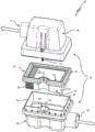
fig. 1a shows a schematic exploded view of a first embodiment of an air filter with a flat air filter element having a recess centrally located on a lateral edge;
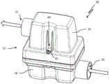
fig. 1b shows the air filter according to fig. 1a in a schematic perspective view;
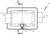
fig. 1c shows the air filter according to fig. 1a in a schematic top view;
FIG. 1d shows the air filter according to FIG. 1a in a schematic cross-section along the cutting plane identified with A-A in FIG. 1 c;
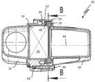
FIG. 1e shows the air filter according to FIG. 1a in a schematic horizontal section along a sectional plane identified by B-B in FIG. 1 d;
fig. 2 shows a second embodiment of an air filter with a flat air filter element with notches in the corner regions in a schematic exploded view;
FIG. 3 shows a third embodiment of an air filter with a flat air filter element with a chamfer in a schematic exploded view;
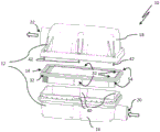
fig. 4a shows a fourth embodiment of an air filter with a flat air filter element with recesses on the side edges and a tensioning spring as a closing element in a schematic exploded view;
fig. 4b shows the air filter according to fig. 4a in a schematic cross-sectional view;
fig. 5 shows a fifth embodiment of an air filter with a tension spring in the corner region and a flat air filter element according to the invention in a schematic exploded view;
fig. 6a shows a sixth embodiment of an air filter in a schematic exploded view, with a plurality of closure elements and with a flat air filter element according to the invention with a plurality of recesses;
FIG. 6b shows the air filter of FIG. 6a with the housing cover removed in a schematic top view;
FIG. 7a shows a seventh embodiment of an air filter in a top view;
FIG. 7b shows, in an enlarged view, the area with the recess of the air filter of FIG. 7 a;
FIG. 7c shows the air filter of FIG. 7a without a housing cover in a perspective illustration, cut perpendicular to the end face of the bellows;
FIG. 8a shows an alternative flat air filter element in a schematic top view;
FIG. 8b shows, in an enlarged view, the area with the recess of the flat air filter element of FIG. 7 a; and
fig. 8c shows a schematic view of the trend along the glued band of unfolded filter media.
Detailed Description
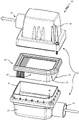
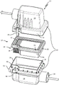
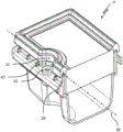
Fig. 1a shows a schematic exploded view of a first embodiment of an air filter 10 according to the invention, having a filter housing 12 and a flat air filter element 14. The filter housing 12 includes a housing canister 16 and a housing cover 18. The inlet of the filter housing for the air to be filtered is designated 20 and the outlet of the filter housing 12 is designated 22. A flat air filter element 14 can be arranged between the housing pot 16 and the housing cover 18.
The flat air filter element 14 includes a filter medium 24 and a sealing element 26, which is circumferentially arranged on the filter medium 24. The filter media 24 is constructed of a cellulosic material. The filter media 24 is zigzag folded and is in the form of a bellows. The filter media 24 is preferably cut before it is folded into a bellows. The filter medium has end edges 28 which are preferably glued together in a waterproof manner, in particular end edge glue joints are formed therefrom. Here, the sealing element 26 is arranged on the upper side on the filter medium 24. The sealing element 26 may be sprayed or foamed onto the filter media 24, among other things. In this connection, the sealing element 26 is made of Polyurethane (PU), preferably polyurethane foam, for example.
The flat air filter element 14 has a recess 32 on its outer contour 30. The recess 32 is formed centrally on a lateral edge 34 of the flat air filter element 14. The recess 32 is embodied here as a domed recess. The recess is rounded in a semicircular manner. The recess can be embodied concavely and directed inwards on the flat air filter element 14. The recess 32 may be embodied uniformly over the filter medium 24 and the sealing element 26, so that the sealing element 26 projects beyond the filter medium 24 by the same distance in all positions.
The housing pot 16 can have a circumferential free edge section 36 on the upper side. The circumferential edge section 36 forms a closure on the upper side of an inner wall 38 of the housing pot 16. The inner wall 38 and the circumferential edge section 36 have a recess 40 on the upper side. The setback 40 can be embodied in particular in correspondence with the recess 32 of the flat air filter element 14. On the housing cover 18, closure elements 42 configured as screws for the housing cover 18 and the housing pot 16 are arranged. The screws may pass through the housing cover 18. Recesses 44 for engaging the screws 42 are formed on the housing pot 16. The recess 44 is formed outside the free edge section 36 in the region of the recess 40 on the housing pot 16.
Fig. 1b shows the air filter 10 according to fig. 1a in a perspective view with a closed filter housing 12. The housing pot 16 and the housing cover 18 are tensioned against one another by the closure element 42. In fig. 1c, the air filter 10 is shown in a top view. A recess 40 is also formed in the housing cover 16. In the region of the retraction 40, screws can be arranged on the outside.
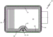
Fig. 1d shows the air filter 10 according to fig. 1a in the installed state in a schematic cross section along the sectional plane identified with a-a in fig. 1 c. A flat air filter element 14 is arranged in the filter housing 12. The sealing element 26 extends beyond the free edge section 36 of the housing pot 16 in a radial direction relative to the longitudinal axis 46 of the filter housing 12. The free edge section 36 of the housing pot 16 engages around into the retaining groove 48 of the sealing element 26. According to embodiments not shown in detail, the retaining groove 48 may also face the housing cover 18. The sealing element 26 of the flat air filter element 14 is thus held in a clamped manner in the axial direction relative to the longitudinal axis 46 of the filter housing 12 between the housing pot 16, in this case its free edge section 36, and the housing cover 18. Furthermore, the free end section 50 of the sealing element 26 can be designed in such a way that it additionally bears in a sealing manner in the radial direction against an annular collar 52 of the housing cover 18. The sealing element 26 is thus embodied in this particular case as a combined radial and axial sealing element.
The annular flange 52 surrounds the housing pot 16 on the outside. The sealing element 26 of the flat air filter element 14 is held in a positionally fixed manner between the two housing parts in a circumferential manner, in particular also in the radial direction, as a result of engagement in the housing side into the retaining groove 48. In this way, a reliable sealing engagement of the flat air filter element 14 in the filter housing 12 is ensured even during operation of the filter under the inflow of the flat air filter element, i.e. under a radially directed tensile load of the sealing element 26. In order to connect the housing pot 16 and the housing cover 18 on the side of the filter housing 12 opposite the closure element 42, a hook element (hidden) can be formed on one of the housing parts 16, 18. The hook elements here preferably engage in corresponding hook recesses (hidden) of the other housing part 16, 18.
FIG. 1e shows air filter 10 in horizontal cross-section along the cross-sectional plane identified by B-B in FIG. 1 d.
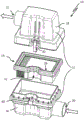
Fig. 2 shows a second embodiment of an air filter 10 with a flat air filter element 14 in an exploded view of the components of the air filter. The air filter 10 differs from the air filter 10 described above in conjunction with fig. 1a to 1e essentially in that the recesses 32 are formed in the corner regions 54 of the flat air filter element 14. The recess 32 can be embodied in particular as an inwardly curved, concave depression of the outer contour 30 of the flat air filter element 14. The screw can be arranged as a closure element 42 in the region of the recess 32.
Fig. 3 shows a third embodiment of the air filter 10 in the form of an exploded view of the components of the air filter. The third embodiment essentially corresponds in its construction to the second embodiment according to fig. 2. Here, the recess 32 is embodied as a chamfer on the corner region 54 of the flat air filter element 14. The edge section 36 of the housing pot 16 may have a setback 40 that fits onto the shape of the chamfer.
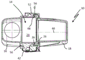
Fig. 4a shows a fourth embodiment of the air filter 10 in an exploded view. A tensioning spring is provided here as the closing element 42. The recess 32 is formed centrally on a lateral edge 34 of the flat air filter element 14. The recess 32 may be configured to be wider than it is deep, in particular at least twice as wide.
Fig. 4b shows the air filter 10 according to fig. 4a in a cross-sectional view at the level of the recess 32 and the tensioning spring. The tensioning spring surrounds the lateral projection 56 of the housing pot 16 and the annular collar 52 of the housing cover 18. In this case, the tension spring can be elastically tensioned. Thereby, the housing pot 16 and the housing cover 18 can be tensioned relative to each other. In this case, the sealing element 26 of the flat air filter element 14 is clamped around between the housing pot 16 and the housing cover 18. The sealing element 26 has a retaining groove 48, into which the housing pot 16 engages with its free edge section.
Fig. 5 shows a fifth embodiment of the air filter 10 in an exploded view, in which a tension spring is used as the closure element 42. The recess 32 of the flat air filter element 14 is formed in the corner region 54. The recess 32 may be implemented with a parallel offset with respect to the side edges 34 of the flat air filter element 14. The tensioning spring can be guided along the recess 32 for closing the housing pot 16 with the housing cover 18. It is thereby possible to prevent the closure element 42 from protruding laterally beyond the outer edge 58 of the housing pot 16.
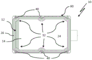
Fig. 6a shows a sixth embodiment of an air filter 10, in which a flat air filter element 14 having a plurality, here, illustratively, six recesses 32 can be formed. The recess 32 is formed, for example, centrally in the corner region 54 and on the side edge 34. To fasten the housing cover 18 to the housing pot 16, the air filter 10 can have a plurality of closure elements 42. The closing element 42 can be configured in the form of a screw or a tension spring or the like.
Fig. 6b shows the air filter 10 according to fig. 6a with the housing cover removed in a schematic top view. The closure element 42 is arranged in the region of the recess 32. The closure element 42 is thereby surrounded by the sealing element 26 of the flat air filter element 14 in the region of the recess 32. A substantially rectangular contour line or outer shape 60 of the air filter 10 can thereby be realized in this plan view, wherein the flat air filter element 14, together with its sealing element 26 and the filter medium 24, sealingly reaches the outer shape 60. In particular, the sealing element 20 may be arranged in the region between the closure elements 42, thereby increasing the filter area of the filter medium 18.
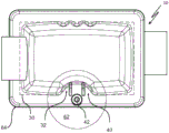
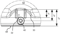
Fig. 7a shows a top view of a seventh embodiment of an air filter 10 with a closure element 42, which is arranged in the region of the setback 40 or the recess 32. Unless otherwise stated, this embodiment may correspond, for example, to the embodiment of the air filter 10 of fig. 1a, in particular to the illustration according to fig. 1 c. The course of the outer contour 30, i.e. therefore of the end edge 28 (fig. 1 a), in particular along the filter medium 24 (fig. 1 a) is shown in dashed lines. In addition, the edge 64 of the air filter 10 can be seen.
Fig. 7b shows, in an enlarged view, the region 62 with the recess 32 of the air filter 10 of fig. 7 a. Thereafter, the recess 32 protrudes to a depth of penetration l1Into the flat air filter element 14 (fig. 1 a), the penetration depth is measured as the distance between the innermost point in the radial direction of the outer contour 30 of the filter medium 24 and the outer contour 30 outside the region of the recess 32. In this embodiment, the penetration depth l1At least 10 mm or 10.5 mm, in particular about 10.8 mm. The center point of the closure element 42 is at a distance l2In this embodiment at a distance of about 15 mm from the innermost point.
Further, in this embodiment, the innermost point is at a distancel3Spaced from the edge 64 by about 22 mm in this embodiment.
As can be seen from the perspective view in fig. 7c of the air filter 10 in fig. 7a, which does not have the housing cover 18 (fig. 1 a) here, in this embodiment the closure element 42 is arranged along an imaginary linear bridging recess 32 of the sealing element 26 and in particular also a continuation 66 of the retraction 40, in particular as shown here along a main sealing surface in the form of a sealing groove surrounding the housing edge.
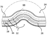
Fig. 8a shows an alternative flat air filter element 14 with a recess 32 in the region 68 in a schematic top view, wherein the region 68 is again shown enlarged in fig. 8 b.
As can be gathered in particular from fig. 8b, the sealing element 26 abuts against the filter medium 24 of the flat air filter element 14, which is designed as a bellows. The filter medium 24 has end edge glue 72 (shown schematically in fig. 8 b) by which the individual folds of the corrugated tube are connected to one another in a sealing manner. The end edge glue 72 extends in the edge region of the filter medium 24, in particular at a distance from the end edge 28.
The sealing element 26 is sealingly connected to the filter media 24 by means of a sealing connection contour 70. In particular, the sealing connection contour 70 surrounds the filter medium 24 in a form-fitting manner in a sealing manner. For this purpose, the sealing connection contour on the clean side exceeds the filter medium. The sealing connection contour 70 is in this embodiment preferably made of a foam material, for example polyurethane.
It can be seen that the sealing connection contour 70, the end edge glue 72 and, in this exemplary embodiment, also the end edges 28 run parallel to one another, in particular in the region of the recesses 32. In the region of the recess 32, the sealing element 26 and the end edge 28 also extend parallel to one another.
It can thus be seen that in this exemplary embodiment, the sealing connection contour 70, the end edge glue 72, the end edge 28 and the sealing element 26 extend parallel to one another in the region of the recess 32.
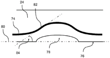
Fig. 8c shows schematically the tendency of the glue strip 74 to rest on the (still) unfolded filter medium 24. For the sake of illustration, only one cutout, in particular the edge region of the filter medium 24, is shown here.
The adhesive strip 74 in this exemplary embodiment extends in particular in an unfolded manner in the edge region of the filter medium 24. The glue strip substantially follows the end edge 76 of the filter media 24, wherein the glue strip is illustratively offset with respect to the end edge toward the interior region of the filter media 24.
In this example, the (unfolded) filter media 24 has recesses 78 from which the notches 32 are subsequently formed by folding. The recess 78 is also surrounded by the glue strip 74. The main direction 80 is obtained along the end edge 76 without taking into account the recess 78.
For an exemplary selected point 82 on the glue strip 74, fig. 8c shows a tangential angle 84 resulting from the inclination of the tangent on the point 82 with respect to the main direction 80. It can be seen in particular that the profile of the adhesive tape 74 is selected such that the tangential angle 84 is implemented flat. In particular in the region of the recess 78, in other words in the region of the (subsequent) recess 32, the tangential angle 84 is at most 45 °, however in the usual case at most 30 °. In this connection, the tendency of the adhesive tape 74 is not parallel to the recesses, in particular in the end regions of the recesses 78 in which the adhesive tape is not bent.
If the filter media 24 is now folded, then the individual folds may be joined to one another to form the end bead bonds 72 (FIG. 8 b). In this case, the course and the width of the adhesive tape 74 are selected in particular such that respectively adjacent sections of the adhesive tape 74 at least partially overlap one another. In the folded state, that is to say in the folded sections which are placed and connected by the end edge glue 72, the end edge glue 72 is preferably embodied at least in the region of the recess, preferably along the entire end face of the flat air filter element at a tangential angle 86 (fig. 8 b) of at most 45 ° relative to the main direction of the folded filter medium, that is to say relative to the end face of the folded filter medium. This means that the curve formed by the parts of the end edge gluing 72 that are visible in the folded state in the region of the folding tip, the course of which is visible in fig. 8b in the form of a dashed line, has an angle 86 of at most 45 ° with respect to the end side and thus an angle of at least 45 ° with respect to the folding edge.
Claims (18)
1. A flat air filter element (14) having a filter medium (24) consisting of a cellulose material, which carries a surrounding sealing element (26),
wherein the sealing element (26) and the filter medium (24) have at least one recess (32) on an outer contour (30) of the flat air filter element (14), and
wherein a circumferential retaining groove (48) is formed on the sealing element (26) for engaging a housing part (16, 18) of the filter housing (12), the flat air filter element (14) has a plurality of recesses (32), the recesses (32) being embodied as arched depressions of the flat air filter element (14), the filter medium (24) has end edges (28) glued to one another in the form of end edge glue (72), the end edge glue (72) in the folded state extending at a tangential angle (86) of at most 45 DEG relative to a main direction (80) of the unfolded filter medium (24) at least in the region of the recess (32), the sealing connection contour (70) of the sealing element (26) and the end edge gluing (72) extend parallel to one another in the region of the recess (32).
2. The flat air filter element according to claim 1, characterized in that the recess (32) is formed in the form of a chamfer on a corner region (54) of the flat air filter element (14).
3. Flat air filter element according to claim 1 or 2, characterised in that the recess (32) is formed centrally on a lateral edge (34) of the flat air filter element (14).
4. The flat air filter element according to claim 1 or 2, characterized in that the recess (32) has a penetration depth (I) of at least 10 mm1)。
5. The flat air filter element according to claim 1 or 2, characterized in that the filter medium (24) is embodied as a zigzag-folded bellows.
6. Flat air filter element according to claim 1 or 2, characterised in that the end edge gluing (72) in the folded state extends at a tangential angle (86) of at most 45 ° relative to the main direction (80) of the unfolded filter medium (24) along the entire end side of the flat air filter element (14), at least in the region of the recess (32).
7. The flat air filter element according to claim 5, characterized in that the sealing connection contour (70) of the sealing element (26) and the end edge gluing (72) extend parallel to one another in the region of the recess (32) along the entire end side of the flat air filter element (14).
8. Flat air filter element according to claim 5, characterised in that the sealing element (26) and the end edge (28) extend parallel to one another in the region of the recess (32) along the entire end face of the flat air filter element (14).
9. Flat air filter element according to claim 5, characterised in that the sealing element (26) and/or the end edge (28) extends parallel to the end edge glue (72) in the region of the recess (32) along the entire end face of the flat air filter element (14).
10. The flat air filter element according to claim 1 or 2, characterized in that the sealing element (26) is made of polyurethane, wherein the sealing element (26) is sprayed or foamed onto the flat air filter element (14).
11. Flat air filter element according to claim 1, characterised in that it is used for an air filter (10) in an intake pipe for an internal combustion engine.
12. Flat air filter element according to claim 4, characterised in that the recess (32) has a penetration depth (I) of at least 10.5 mm1)。
13. An air filter (10) comprising:
-a filter housing (12) having a housing pot (16) and a housing cover (18), and a closure element (42) for closing the filter housing (12); and
-a flat air filter element (14) arranged in the filter housing (12) according to any of the preceding claims,
wherein the flat air filter element (14) is held with its sealing element (26) in a surrounding clamping manner between the housing pot (16) and the housing cover (18) in the closed state of the filter housing (12),
wherein the housing pot (16) or the housing cover (18) engages into a retaining groove (48) of the sealing element (26), and
wherein a closure element (42) of the filter housing (12) is arranged in the region of the recess (32).
14. The air filter according to claim 13, characterized in that the closure element (42) is arranged along or substantially along a linear continuation (66) of the sealing element (26) bridging the recess (32).
15. An air filter according to claim 13 or 14, characterised in that the closing element (42) is a tension spring, screw or other tensioning element.
16. The air filter according to claim 13 or 14, characterized in that the housing cover (18) and the housing tank (16) are connected to each other with a hinge and a tensioning element arranged on the housing side arranged opposite the recess (32) of the flat air filter element (14), facing away from the recess (32).
17. The air filter according to claim 13 or 14, characterized in that the filter housing (12) has a number of closure elements (42) and the flat air filter element (14) has a number of recesses (32) corresponding to the number of closure elements (42).
18. The air filter according to claim 16, characterized in that the housing cover (18) and the housing pot (16) are connected to each other by means of a tension spring or a screw facing away from the recess (32).
Applications Claiming Priority (3)
| Application Number | Priority Date | Filing Date | Title |
|---|---|---|---|
| DE102016005088.8 | 2016-04-27 | ||
| DE102016005088 | 2016-04-27 | ||
| PCT/EP2017/059993 WO2017186820A1 (en) | 2016-04-27 | 2017-04-26 | Flat air filter element and air filter |
Publications (2)
| Publication Number | Publication Date |
|---|---|
| CN109072827A CN109072827A (en) | 2018-12-21 |
| CN109072827B true CN109072827B (en) | 2021-06-04 |
Family
ID=58707496
Family Applications (1)
| Application Number | Title | Priority Date | Filing Date |
|---|---|---|---|
| CN201780026185.5A Active CN109072827B (en) | 2016-04-27 | 2017-04-26 | Flat air filter element and air filter |
Country Status (6)
| Country | Link |
|---|---|
| US (1) | US10662905B2 (en) |
| EP (1) | EP3449113B1 (en) |
| CN (1) | CN109072827B (en) |
| BR (1) | BR112018068528B1 (en) |
| DE (2) | DE112017002216A5 (en) |
| WO (1) | WO2017186820A1 (en) |
Families Citing this family (12)
| Publication number | Priority date | Publication date | Assignee | Title |
|---|---|---|---|---|
| US11167234B2 (en) | 2016-03-18 | 2021-11-09 | Cummins Filtration Ip, Inc. | Interlocked stable filter assembly |
| DE102016004315A1 (en) * | 2016-04-12 | 2017-10-12 | Mann + Hummel Gmbh | A filter assembly |
| DE102016013844A1 (en) * | 2016-11-22 | 2018-05-24 | Mann + Hummel Gmbh | Round filter element with elongated cross-sectional shape |
| US11724220B2 (en) | 2017-02-21 | 2023-08-15 | Cummins Filtration Ip, Inc. | Undulated interlocking housing-endplate interface geometry |
| CN115155166B (en) * | 2017-03-16 | 2024-01-26 | 康明斯滤清系统知识产权公司 | Filtration sealing system |
| AU2018313187B2 (en) * | 2017-08-09 | 2023-11-09 | Donaldson Company, Inc. | Filter cartridges; air cleaner assemblies; housings; features; components; and, methods |
| CN110559751B (en) * | 2018-06-05 | 2022-11-01 | 上海欧菲滤清器有限公司 | Panel air filter, drawer element, and air filter assembly |
| USD1002792S1 (en) | 2019-02-05 | 2023-10-24 | Donaldson Company, Inc. | Filter cartridge |
| WO2021108372A1 (en) * | 2019-11-25 | 2021-06-03 | Abc Technologies Inc. | Air cleaner apparatus with fastener |
| DE102021117356B4 (en) | 2020-07-16 | 2024-01-11 | Dräger Safety AG & Co. KGaA | Pleated filter element and its use, filter and method for producing the filter element and the filter |
| DE102021119815A1 (en) * | 2020-07-31 | 2022-02-03 | Mann+Hummel Gmbh | Filter element with filter medium folded in a zigzag shape with discontinuous front edge bonding and method for producing such a material |
| WO2022115423A1 (en) * | 2020-11-24 | 2022-06-02 | Cummins Filtration Inc. | Arched air filter |
Citations (6)
| Publication number | Priority date | Publication date | Assignee | Title |
|---|---|---|---|---|
| CN1978885A (en) * | 2005-12-06 | 2007-06-13 | 本田技研工业株式会社 | Air cleaner equipment and method for manufacturing thereof |
| CN200961548Y (en) * | 2006-10-20 | 2007-10-17 | 重庆长安汽车股份有限公司 | Air filter of automobile |
| CN203374400U (en) * | 2013-07-03 | 2014-01-01 | 美嘉帕拉斯特汽车零部件(上海)有限公司 | Air filter box for vehicle |
| WO2015075104A1 (en) * | 2013-11-20 | 2015-05-28 | Mann+Hummel Gmbh | Filter element having filter bellows |
| CN204610087U (en) * | 2013-11-28 | 2015-09-02 | 曼·胡默尔有限公司 | Filter cell and filter system |
| DE102015011661A1 (en) * | 2014-09-12 | 2016-03-17 | Mann + Hummel Gmbh | Filter element for a filter device for gas filtration |
Family Cites Families (33)
| Publication number | Priority date | Publication date | Assignee | Title |
|---|---|---|---|---|
| DE2137309C3 (en) | 1971-07-26 | 1979-08-02 | Purolator Filter Gmbh, 7110 Oehringen | Filter with a pleated block made of a zigzag folded filter paper strip impregnated with thermoplastic synthetic resin |
| DE4328846C2 (en) | 1993-08-27 | 1999-05-20 | Mann & Hummel Filter | Process for producing a filter insert and filter insert produced by this method |
| JP3299622B2 (en) * | 1994-03-11 | 2002-07-08 | 豊田紡織株式会社 | Air cleaner device |
| DE4435532A1 (en) | 1994-10-05 | 1996-04-11 | Mann & Hummel Filter | Process for the production of filters |
| IN189834B (en) | 1997-04-18 | 2003-04-26 | Mann & Hummel Filter | |
| DE19824506C1 (en) | 1998-06-02 | 1999-07-01 | Freudenberg Carl Fa | Fluid filter made from folded fleece sealed at edges by tape and incorporating |
| DE19859854A1 (en) | 1998-12-23 | 2000-06-29 | Mann & Hummel Filter | Filters with a housing reinforced by at least one reinforcement |
| DE20310833U1 (en) | 2003-07-14 | 2004-11-18 | B & S Industrieservice Gmbh | Filter insert for use in air inlet ducts for car heaters comprises section cut from a bellows strip to give a diagonal surface, triangular plastic component being fixed to surface and filling gap between insert and duct walls |
| DE102004002293A1 (en) | 2004-01-16 | 2005-07-14 | Audi Ag | Air filter used as dry air filter for vehicle engine comprises pure air line leading from pure air chamber through opening of filter element and through crude air chamber to air outlet |
| WO2007090778A1 (en) | 2006-02-09 | 2007-08-16 | Mann+Hummel Gmbh | Filter element for an air filter |
| WO2008051936A2 (en) | 2006-10-20 | 2008-05-02 | Cummins Filtration Ip | Apparatus, system, and method for manufacturing irregularly shaped panel filters |
| WO2009015684A1 (en) | 2007-07-27 | 2009-02-05 | Mann+Hummel Gmbh | Air filter, especially for internal combustion engines in motor vehicles, and method for the production of such an air filter |
| DE202008015078U1 (en) | 2008-11-13 | 2010-04-08 | Mann+Hummel Gmbh | Air filter element |
| DE202009000969U1 (en) | 2009-01-26 | 2010-07-01 | Mann+Hummel Gmbh | filter element |
| DE202009002178U1 (en) | 2009-02-16 | 2010-07-15 | Mann+Hummel Gmbh | Filter device for the filtration of gaseous fluids |
| JP5656430B2 (en) | 2010-03-23 | 2015-01-21 | 本田技研工業株式会社 | Air cleaner device |
| DE102010053200A1 (en) | 2010-12-03 | 2012-06-06 | Carl Freudenberg Kg | Filter element for use as cabin air filter element in air or ventilation system, has cover edge and shorter side edge connected with each other, and bellows comprising rectangular and square trapezoidal partial bellows |
| CN103282638B (en) | 2011-01-11 | 2017-02-08 | 曼·胡默尔有限公司 | Air cleaner assembly and air filter element |
| DE102011078057A1 (en) * | 2011-06-24 | 2013-01-10 | Mahle International Gmbh | Plate filter element |
| EP2802402B1 (en) * | 2012-01-13 | 2019-06-05 | MANN+HUMMEL GmbH | Air filter element having a specific retaining geometry |
| DE102012005530A1 (en) | 2012-03-21 | 2013-09-26 | Mann+Hummel Gmbh | Method for producing a filter element provided with a sealing part |
| JP2013227965A (en) * | 2012-03-28 | 2013-11-07 | Yamaha Motor Co Ltd | Saddle type vehicle |
| DE102012013470A1 (en) | 2012-07-09 | 2014-05-08 | Mann + Hummel Gmbh | Method and device for manufacturing filter elements and filter element |
| DE102014015907A1 (en) | 2013-11-20 | 2015-05-21 | Mann + Hummel Gmbh | Apparatus and method for producing a filter bellows of a flat filter element for fluids and a flat filter element for fluids with a bellows |
| WO2015074806A1 (en) | 2013-11-20 | 2015-05-28 | Mann+Hummel Gmbh | Filter element having a filter bellows |
| CN106573184B (en) | 2014-07-25 | 2019-07-19 | 康明斯过滤Ip公司 | The filter element of modified filter medium packet characteristic |
| DE102014013280A1 (en) | 2014-09-12 | 2016-03-17 | Mann + Hummel Gmbh | Filter device for gas filtration and filter element for a filter device for gas filtration |
| DE102014013278A1 (en) | 2014-09-12 | 2016-03-17 | Mann + Hummel Gmbh | Plate-shaped filter element for gas filtration |
| DE102015011660A1 (en) | 2014-09-12 | 2016-03-17 | Mann + Hummel Gmbh | Filter device for gas filtration |
| DE102015016236A1 (en) * | 2015-01-23 | 2016-07-28 | Mann+Hummel Gmbh | Filter element with several superimposed single sheets |
| DE102015005565A1 (en) | 2015-05-04 | 2016-11-10 | Mann + Hummel Gmbh | Method for producing filter bellows |
| DE102015016237A1 (en) | 2015-12-16 | 2017-06-22 | Mann+Hummel Gmbh | Filter bellows and filter element |
| DE102015226754A1 (en) * | 2015-12-28 | 2017-06-29 | Mahle International Gmbh | filtering device |
-
2017
- 2017-04-26 CN CN201780026185.5A patent/CN109072827B/en active Active
- 2017-04-26 EP EP17723296.4A patent/EP3449113B1/en active Active
- 2017-04-26 BR BR112018068528-3A patent/BR112018068528B1/en active IP Right Grant
- 2017-04-26 WO PCT/EP2017/059993 patent/WO2017186820A1/en active Application Filing
- 2017-04-26 DE DE112017002216.9T patent/DE112017002216A5/en active Pending
- 2017-04-26 DE DE102017003997.6A patent/DE102017003997A1/en active Pending
-
2018
- 2018-10-28 US US16/172,821 patent/US10662905B2/en active Active
Patent Citations (6)
| Publication number | Priority date | Publication date | Assignee | Title |
|---|---|---|---|---|
| CN1978885A (en) * | 2005-12-06 | 2007-06-13 | 本田技研工业株式会社 | Air cleaner equipment and method for manufacturing thereof |
| CN200961548Y (en) * | 2006-10-20 | 2007-10-17 | 重庆长安汽车股份有限公司 | Air filter of automobile |
| CN203374400U (en) * | 2013-07-03 | 2014-01-01 | 美嘉帕拉斯特汽车零部件(上海)有限公司 | Air filter box for vehicle |
| WO2015075104A1 (en) * | 2013-11-20 | 2015-05-28 | Mann+Hummel Gmbh | Filter element having filter bellows |
| CN204610087U (en) * | 2013-11-28 | 2015-09-02 | 曼·胡默尔有限公司 | Filter cell and filter system |
| DE102015011661A1 (en) * | 2014-09-12 | 2016-03-17 | Mann + Hummel Gmbh | Filter element for a filter device for gas filtration |
Also Published As
| Publication number | Publication date |
|---|---|
| US10662905B2 (en) | 2020-05-26 |
| EP3449113B1 (en) | 2024-03-27 |
| DE102017003997A1 (en) | 2017-11-02 |
| BR112018068528B1 (en) | 2022-12-06 |
| DE112017002216A5 (en) | 2019-01-10 |
| US20190063380A1 (en) | 2019-02-28 |
| WO2017186820A1 (en) | 2017-11-02 |
| EP3449113A1 (en) | 2019-03-06 |
| CN109072827A (en) | 2018-12-21 |
| BR112018068528A2 (en) | 2019-01-29 |
Similar Documents
| Publication | Publication Date | Title |
|---|---|---|
| CN109072827B (en) | Flat air filter element and air filter | |
| JP6172864B2 (en) | Air filter element having a retaining shape | |
| JP6091522B2 (en) | Air filter element having a retaining shape | |
| US7708796B2 (en) | Axial flow filter element | |
| JP6214555B2 (en) | Air filter element having a retaining shape | |
| US7442221B2 (en) | Filter element | |
| US10384158B2 (en) | Filter element having filter bellows | |
| US8206625B2 (en) | Filter element | |
| CN102223940B (en) | Intake air filter for internal combustion engines | |
| KR100319346B1 (en) | Filters, especially air filters for air intakes of internal combustion engines | |
| JP5711857B2 (en) | Air filter | |
| US20090205302A1 (en) | Compact air filter element with knock protection | |
| AU2007215115A1 (en) | Fluted filter apparatus | |
| US8182570B2 (en) | Compact air filter element | |
| US10786773B2 (en) | Filter element | |
| US8308835B2 (en) | Cylindrical filter element | |
| US20190209960A1 (en) | Air filter | |
| AU2017379787B2 (en) | Filter with preformed end caps having notch feature | |
| CN107206301B (en) | Filter element | |
| US10550802B2 (en) | Air cleaner for internal combustion engine | |
| US20100051537A1 (en) | Filter Element with Glued-On Terminal Disk | |
| US20230241540A1 (en) | Filter element | |
| CN108590898B (en) | Air filter |
Legal Events
| Date | Code | Title | Description |
|---|---|---|---|
| PB01 | Publication | ||
| PB01 | Publication | ||
| SE01 | Entry into force of request for substantive examination | ||
| SE01 | Entry into force of request for substantive examination | ||
| GR01 | Patent grant | ||
| GR01 | Patent grant |