CN109047231B - Large-diameter fruit glass can body flushing device - Google Patents
Large-diameter fruit glass can body flushing device Download PDFInfo
- Publication number
- CN109047231B CN109047231B CN201810809492.7A CN201810809492A CN109047231B CN 109047231 B CN109047231 B CN 109047231B CN 201810809492 A CN201810809492 A CN 201810809492A CN 109047231 B CN109047231 B CN 109047231B
- Authority
- CN
- China
- Prior art keywords
- positioning
- transverse
- fixedly connected
- arc
- cylinder
- Prior art date
- Legal status (The legal status is an assumption and is not a legal conclusion. Google has not performed a legal analysis and makes no representation as to the accuracy of the status listed.)
- Active
Links
Images


Classifications
-
- B—PERFORMING OPERATIONS; TRANSPORTING
- B08—CLEANING
- B08B—CLEANING IN GENERAL; PREVENTION OF FOULING IN GENERAL
- B08B9/00—Cleaning hollow articles by methods or apparatus specially adapted thereto
- B08B9/08—Cleaning containers, e.g. tanks
- B08B9/20—Cleaning containers, e.g. tanks by using apparatus into or on to which containers, e.g. bottles, jars, cans are brought
- B08B9/28—Cleaning containers, e.g. tanks by using apparatus into or on to which containers, e.g. bottles, jars, cans are brought the apparatus cleaning by splash, spray, or jet application, with or without soaking
-
- B—PERFORMING OPERATIONS; TRANSPORTING
- B08—CLEANING
- B08B—CLEANING IN GENERAL; PREVENTION OF FOULING IN GENERAL
- B08B13/00—Accessories or details of general applicability for machines or apparatus for cleaning
-
- B—PERFORMING OPERATIONS; TRANSPORTING
- B08—CLEANING
- B08B—CLEANING IN GENERAL; PREVENTION OF FOULING IN GENERAL
- B08B9/00—Cleaning hollow articles by methods or apparatus specially adapted thereto
- B08B9/08—Cleaning containers, e.g. tanks
- B08B9/20—Cleaning containers, e.g. tanks by using apparatus into or on to which containers, e.g. bottles, jars, cans are brought
- B08B9/36—Cleaning containers, e.g. tanks by using apparatus into or on to which containers, e.g. bottles, jars, cans are brought the apparatus cleaning by using brushes
Abstract
The invention relates to the technical field of fruit glass can cleaning, and discloses a large-caliber fruit glass can body washing device which comprises a machine body, wherein the bottom of the machine body is fixedly connected with a low-speed motor through a fixing frame, an output shaft of the low-speed motor is fixedly connected with a torque rotating shaft through a coupler, one end, far away from the low-speed motor, of the torque rotating shaft penetrates through the bottom of the machine body and is fixedly connected with a rotating table, the bottom of the inner side of the machine body is fixedly connected with a circular chute matched with the outer diameter of the rotating table through bolts, the bottom of the rotating table is movably connected with movable balls, and the bottoms of the movable balls are positioned. The invention solves the problems of high labor intensity and high cost of cleaning the glass can body by arranging the machine body, the low-speed motor, the torque rotating shaft, the rotating platform, the positioning supporting cylinder, the adjusting and positioning mechanism, the vertical circulating mechanism, the transverse positioning mechanism, the rotating motor, the disc type cleaning brush, the spraying head and the control panel to be matched with each other.
Description
Technical Field
The invention relates to the technical field of fruit glass can cleaning, in particular to a large-caliber fruit glass can body washing device.
Background
The glass cans are generally crisp and easy to break, especially the fruit glass cans need to be thoroughly sterilized and cleaned when fruits are stored to achieve the purpose of safe eating, the fruit cans generally adopt glass cans to store the fruits, the glass cans can be repeatedly recycled, the manufacturing cost of the fruit cans is reduced, especially the large-caliber fruit glass cans need to be cleaned and sterilized firstly, when the large-caliber glass cans are cleaned traditionally, the bodies of the glass cans are generally manually cleaned and scrubbed by a scrubbing brush to achieve the purpose of cleaning, the bodies of the glass cans are manually cleaned and cleaned with large labor amount, and the edges and corners of some glass cans are easy to scratch or hold by hands of operators, are easy to break, when equipment is adopted to clean the bodies of the glass cans, the body of glass can needs to be clamped, the side part of the glass can body clamped by the clamping can body cannot be thoroughly cleaned, secondary reworking cleaning is needed, the cost for cleaning the large-caliber glass can body is increased, and therefore the large-caliber fruit glass can body washing equipment is needed to wash the body of the glass can, and the labor intensity and cost for cleaning the glass can are reduced.
Disclosure of Invention
Technical problem to be solved
Aiming at the defects of the prior art, the invention provides a large-caliber fruit glass can body washing device, which solves the problems of high labor intensity and high cost of cleaning a glass can body.
(II) technical scheme
In order to achieve the purpose, the invention provides the following technical scheme: a large-diameter fruit glass can body washing device comprises a machine body, wherein the bottom of the machine body is fixedly connected with a low-speed motor through a fixing frame, an output shaft of the low-speed motor is fixedly connected with a torque rotating shaft through a coupler, one end of the torque rotating shaft, far away from the low-speed motor, penetrates through the bottom of the machine body and is fixedly connected with a rotating table, the bottom of the inner side of the machine body is fixedly connected with a circular sliding groove matched with the outer diameter of the rotating table through a bolt, the bottom of the rotating table is movably connected with a movable ball, the bottom of the movable ball is positioned on the inner side of the circular sliding groove, the middle position of the upper surface of the rotating table is fixedly connected with a positioning support cylinder through a bolt, the top of the positioning support cylinder is bonded with a flexible sponge layer, a circular limiting disc is fixedly inserted in the side surface of the, the top of the fixed table is connected with a vertical circulation mechanism, the vertical circulation mechanism is connected with a transverse positioning mechanism, the bottom of the transverse positioning mechanism is connected with a rotating motor, an output shaft of the rotating motor is fixedly connected with a disc type cleaning brush through a connector, a sprinkler head is arranged on the right side of the rotating motor at the bottom of the transverse positioning mechanism, a water inlet of the sprinkler head is externally connected with a telescopic hose, an adjusting through groove is formed in the left side of the machine body, a switch door is arranged on the front side of the machine body, a drain pipe is fixedly connected to a drain port on the right side of the.
Preferably, the adjusting and positioning mechanism comprises a transverse polish rod, a star-shaped handle, a forward thread, a reverse thread, a screw nut, a transverse positioning slide rail, a connecting slide block, a connecting hinge seat, a positioning hinge seat, an arc elastic sheet, an arc through groove, a pressing and positioning mechanism and a pushing roller, wherein the inner side of the positioning support cylinder is provided with the transverse polish rod, two ends of the transverse polish rod respectively penetrate through the inner walls of the left side and the right side of the positioning support cylinder and extend to the outer side of the positioning support cylinder, the two ends of the transverse polish rod outside the positioning support cylinder are both fixedly connected with the star-shaped handle, the part of the transverse polish rod inside the positioning support cylinder is symmetrically provided with the forward thread and the reverse thread, the parts of the transverse polish rod, which are both threaded, are respectively sleeved with the screw nut, the inner walls of the two sides of the positioning support cylinder are fixedly connected with the, the bottom of two link blocks respectively with two screw-nut fixed connection, the articulated seat of the equal fixedly connected with in top of two link blocks, the articulated seat of the equal fixedly connected with location of the left and right sides inner wall of a location support section of thick bamboo, equal fixedly connected with arc elasticity piece on the articulated seat of two location, the bottom of two arc elasticity pieces is fixed connection at two articulated seats of connection respectively, the top of two arc elasticity pieces all has the promotion gyro wheel through activity pivot swing joint, the arc logical groove has all been seted up at the side top about the location support section of thick bamboo, the inboard equal swing joint that two arcs led to the groove has compressing positioning mechanism, two promotion gyro wheels contact with two compressing positioning mechanisms respectively, fixedly connected with reset connection spring between two compressing positioning mechanisms.
Preferably, the pressing and positioning mechanism comprises a positioning movable shaft and an arc-shaped positioning sheet plate, arc spout and friction rubber head, equal fixedly connected with location loose axle between the inside wall that two arcs led to the groove, equal activity interlude has the arc positioning plate on two location loose axles, the radian radius size looks adaptation that two arc positioning plates and two arcs led to the groove, both ends fixed connection with reset connection spring between the side top that two arc positioning plates are relative respectively, the arc spout has all been seted up to the bottom of two arc positioning plate opposite flank, two promotion gyro wheels are located the inboard of corresponding arc spout respectively, the side that two arc positioning plates carried on the back mutually all bonds and has the friction rubber head, friction rubber head evenly distributed is in the side that two arc positioning plates carried on the back mutually, the length of friction rubber head reduces from the top to the bottom of arc positioning plate in proper order.
Preferably, the vertical circulating mechanism comprises a supporting adjusting cylinder, a servo motor, a ball nut, a vertical adjusting screw rod, a connecting movable through groove, a connecting movable block and a fixed mounting plate, the top of the fixed platform is fixedly connected with the supporting adjusting cylinder through a bolt, the top of the supporting adjusting cylinder is fixedly connected with the servo motor through a bolt, an output shaft of the servo motor penetrates through the top of the supporting adjusting cylinder and is fixedly connected with the vertical adjusting screw rod through a coupler, the vertical adjusting screw rod is movably connected to the top of the fixed platform through a bearing base at one end far away from the servo motor, the ball nut is sleeved on the vertical adjusting screw rod, the connecting movable through groove is formed in the front of the supporting adjusting cylinder, the connecting movable block is movably connected to the inner side of the connecting movable through groove, the back of the connecting movable block is fixedly connected with the ball nut, the lower surface of the fixed mounting plate is fixedly connected with the transverse positioning mechanism through bolts.
Preferably, the transverse positioning mechanism comprises a transverse positioning cylinder, a transverse push-pull screw rod, a transverse push-pull nut, a transverse movable through groove, a transverse movable clamping block, a bearing plate and a limiting ring, the front side of the lower surface of the fixed mounting plate is fixedly connected with the transverse positioning cylinder through bolts, the inner side of the transverse positioning cylinder is provided with the transverse push-pull screw rod, one end of the transverse push-pull screw rod is movably connected with the inner wall of the right side of the transverse positioning cylinder through a bearing base, the other end of the transverse push-pull screw rod penetrates through the inner side wall of the transverse positioning cylinder and extends to the outer side of the transverse positioning cylinder, one end of the transverse push-pull screw rod outside the transverse positioning cylinder is fixedly connected with a rotating handle, the transverse push-pull screw rod is in threaded connection with the push-pull nut, the bottom of the transverse positioning cylinder is provided with, the bottom of the transverse movable clamping block is fixedly connected with a bearing plate, the lower surface of the bearing plate is fixedly connected with a rotating motor and a sprinkler head through bolts respectively, a limiting ring is fixedly inserted on the transverse push-pull lead screw in a penetrating manner, and the limiting ring is positioned on the left side of the external thread of the transverse push-rod lead screw.
Preferably, the control panel is electrically connected with the low-speed motor, the servo motor and the rotating motor, and controls the on-off and running states of the low-speed motor, the servo motor and the rotating motor.
Preferably, the centers of the rotating platform, the torque rotating shaft, the positioning supporting cylinder and the circular sliding groove are on the same vertical line.
Preferably, the disc type cleaning brush is positioned above the left side of the positioning and supporting cylinder, and the positioning hinge seats on the inner walls of the left side and the right side of the positioning and supporting cylinder are arranged in a left-right symmetry mode relative to the center of the positioning and supporting cylinder.
Preferably, the material that the arc-shaped elastic piece adopted is spring steel 65Mn, and the thickness that the arc-shaped elastic piece adopted is 5 millimeters.
(III) advantageous effects
The invention provides a large-caliber fruit glass can body washing device. The method has the following beneficial effects:
(1) the invention is characterized in that a machine body, a low-speed motor, a torque rotating shaft, a rotating platform, a positioning support cylinder, an adjusting and positioning mechanism, a vertical circulating mechanism, a transverse positioning mechanism, a rotating motor, a disc type cleaning brush, a sprinkler head and a control panel are matched with each other, when the device is used, a glass can to be cleaned is sleeved on the positioning support cylinder, a flexible sponge layer protects the inner side bottom of the glass can, then the adjusting and positioning mechanism is used for extruding and positioning the glass can from the inner side, the traditional mode of clamping and fixing the glass can is changed, the glass can body does not need to be clamped and fixed, the cleaning area of the glass can body is increased, then the low-speed motor, the rotating motor and a servo motor are started through the control panel, a flexible hose on the sprinkler head is externally connected with water supply equipment for supplying water, so that the sprinkler head sprays water, an output shaft of the low-speed motor, the moment of torsion pivot drives the revolving stage and rotates, the movable ball of revolving stage bottom is rotatory in the inboard of ring spout, the revolving stage drives a location support section of thick bamboo and rotates, make a location support section of thick bamboo drive fixed glass can and rotate, at this moment, the activity of circulation about vertical circulation mechanism carries out under servo motor's drive, and rotary motor's output shaft drives the disk cleaning brush through the connector and rotates, the disk cleaning brush is rotatory to the glass can and is scrubbed, the brush hair of disk cleaning brush is square rotation on the contrary of the body of glass can, accelerate the cleaning speed of glass can body, thereby the purpose of washing the body of glass can on the ground, the problem that the glass can body carries out abluent intensity of labour and cost is great has been solved.
(2) The invention is characterized in that a machine body, a low-speed motor, a torque rotating shaft, a rotating platform, a positioning support cylinder, an adjusting and positioning mechanism, a vertical circulating mechanism, a transverse positioning mechanism, a rotating motor, a disc type cleaning brush, a sprinkler head and a control panel are matched with each other, when the device is used, a glass can is sleeved on the positioning support cylinder through a bottle opening, a circular limiting disc limits the bottle opening of the glass can to prevent the glass can with overlong bottle body from being inconvenient to position, then a star-shaped handle is rotated to drive the transverse polished rod to rotate, so that a forward thread and a reverse thread on the transverse polished rod drive corresponding screw rod nuts to move relatively, the two screw rod nuts respectively drive corresponding connecting slide blocks to move on the inner side of a transverse positioning slide rail, the connecting slide blocks drive connecting hinge seats to move relatively, the two connecting hinge seats respectively drive two arc-shaped elastic pieces to, the two arc-shaped elastic pieces move in an arc shape by taking the corresponding positioning hinge seats as a circle, so that the pushing rollers at the tail ends of the arc-shaped elastic pieces push the inner wall of the arc-shaped chute of the arc-shaped positioning piece plate, so that the pushing roller moves in the arc chute and pushes the arc positioning sheet plate, the arc-shaped positioning sheet plate protrudes out of the inner side of the arc-shaped through groove, so that the friction rubber head at the bottom of the side surface of the arc-shaped positioning sheet plate contacts the inner side wall of the glass can sleeved on the positioning support cylinder and rotates along with the star-shaped handle, so that the friction rubber head extrudes the inner side wall of the glass can, the two arc-shaped positioning sheet plates simultaneously contact and extrude the glass can through the corresponding friction rubber head, therefore, the purpose of fixing the glass can is achieved, the mode of positioning the traditional glass can is changed, and the cleaning area of the body of the glass can is increased.
(3) The invention is characterized in that a machine body, a low-speed motor, a torque rotating shaft, a rotating platform, a positioning support cylinder, an adjusting and positioning mechanism, a vertical circulating mechanism, a transverse positioning mechanism, a rotating motor, a disc type cleaning brush, a sprinkler head and a control panel are matched with each other, when the device is used, a glass can to be cleaned is sleeved on the positioning support cylinder, a flexible sponge layer protects the inner side bottle bottom of the glass can, then the glass can is extruded and positioned from the inner side by using the adjusting and positioning mechanism, after the glass can is fixed, the low-speed motor, the rotating motor and a servo motor are started through the control panel, a flexible hose on the sprinkler head is externally connected with water supply equipment for supplying water, so that the sprinkler head sprays water, an output shaft of the low-speed motor drives the torque rotating shaft to rotate through a coupler, the torque rotating shaft drives the rotating platform to rotate, and movable balls at, the rotary table is guaranteed to be stressed and shared after being subjected to external force washing acting force of the disc type cleaning brush, the rotary table is guaranteed to be stable in rotation, the rotary table drives the positioning supporting cylinder to rotate, the positioning supporting cylinder drives the fixed glass can to rotate, at the moment, an output shaft of a servo motor drives the vertical adjusting screw to rotate through a coupler, the vertical adjusting screw drives the ball nut to move, the ball nut drives the connecting movable block to move on the inner side of the connecting movable through groove, the connecting movable block drives the fixed mounting plate to move, the fixed mounting plate drives the transverse positioning mechanism to move up and down, the transverse positioning mechanism drives the rotary motor to move, the rotary motor drives the disc type cleaning brush to rotate through the connector, the disc type cleaning brush rotationally cleans the glass can, and bristles of the disc type cleaning brush reversely and squarely rotate the body of the glass, the cleaning speed of the glass can body is accelerated, the vertical circulating mechanism drives the rotating motor to lift up and down through the transverse positioning mechanism, so that the disc type cleaning brush is driven to comprehensively clean the glass can body, and the cleaning speed and efficiency of the glass can body are improved.
(4) The invention is characterized in that a machine body, a low-speed motor, a torque rotating shaft, a rotating platform, a positioning supporting cylinder, an adjusting and positioning mechanism, a vertical circulating mechanism, a transverse positioning mechanism, a rotating motor, a disk type cleaning brush, a sprinkler head and a control panel are matched with each other, when the device is used, a glass can to be cleaned is sleeved on the positioning supporting cylinder, then the adjusting and positioning mechanism is used for extruding and positioning the glass can from the inner side, after the glass can is fixed, the low-speed motor, the rotating motor and a servo motor are started through the control panel, a telescopic hose on the sprinkler head is externally connected with water supply equipment for supplying water, so that the sprinkler head sprays water, the vertical circulating mechanism drives the rotating motor to lift up and down through the transverse positioning mechanism, thereby driving the disk type cleaning brush to comprehensively clean the body of the glass can, and rotating the rotating handle while cleaning, make the twist grip drive horizontal push-and-pull lead screw and rotate, rotatory horizontal push-and-pull lead screw drives horizontal push-and-pull nut and moves, horizontal push-and-pull nut drives horizontal movable fixture block and moves in horizontal activity logical inslot, make horizontal movable fixture block drive the loading board and carry out horizontal activity, thereby make the loading board drive the rotating electrical machines and move about, reach the distance between regulation disc cleaning brush and the fixed glass can, thereby reach the brush hair of adjusting the disc cleaning brush and act on the dynamics of scrubbing of glass can body, can adjust the friction effort between disc cleaning brush and the glass can that need carry out the washing according to specific scrubbing needs, the cleaning quality of effectual improvement glass can body.
Drawings
FIG. 1 is a schematic structural view of the present invention;
FIG. 2 is a schematic view of the connection structure of the positioning support cylinder and the adjusting and positioning mechanism of the present invention;
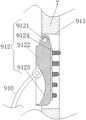
FIG. 3 is a schematic view of the connecting structure of the pressing and positioning mechanism and the positioning and supporting cylinder of the present invention;
FIG. 4 is a schematic side view of the vertical circulation mechanism of the present invention;
FIG. 5 is a schematic view of the vertical circulation mechanism, lateral positioning mechanism and rotary motor connection of the present invention;
FIG. 6 is a schematic view of the present invention.
In the figure: 1 machine body, 2 low-speed motor, 3 torque rotating shaft, 4 rotating platform, 5 circular sliding groove, 6 movable ball, 7 positioning supporting cylinder, 8 circular limiting disc, 9 adjusting and positioning mechanism, 91 horizontal polished rod, 92 star-shaped handle, 93 forward thread, 94 reverse thread, 95 screw rod nut, 96 horizontal positioning sliding rail, 97 connecting sliding block, 98 connecting hinged seat, 99 positioning hinged seat, 910 arc elastic sheet, 911 arc through groove, 912 pressing and positioning mechanism, 9121 positioning movable shaft, 9122 arc positioning sheet plate, 9123 arc sliding groove, 9124 friction rubber head, 913 pushing roller, 10 fixed platform, 11 vertical circulating mechanism, 111 supporting and adjusting cylinder, 112 servo motor, 113 ball nut, 114 vertical adjusting screw rod, 115 connecting movable through groove, 116 connecting movable block, 117 fixed mounting plate, 12 horizontal positioning mechanism, 121 horizontal positioning cylinder, 122 horizontal screw rod, 123 horizontal push-pull nut, 124 transverse movable through grooves, 125 transverse movable clamping blocks, 126 bearing plates, 127 limiting rings, 13 rotating motors, 14 disc type cleaning brushes, 15 spray heads, 16 adjusting through grooves, 17 drain pipes, 18 control panels and 19 flexible sponge layers.
Detailed Description
The technical solutions in the embodiments of the present invention will be clearly and completely described below with reference to the drawings in the embodiments of the present invention, and it is obvious that the described embodiments are only a part of the embodiments of the present invention, and not all of the embodiments. All other embodiments, which can be derived by a person skilled in the art from the embodiments given herein without making any creative effort, shall fall within the protection scope of the present invention.
As shown in fig. 1 to 6, the present invention provides a technical solution: a large-diameter fruit glass can body flushing device comprises a machine body 1, the bottom of the machine body 1 is fixedly connected with a low-speed motor 2 through a fixing frame, the low-speed motor 2 adopts a low-speed torque motor, an output shaft of the low-speed motor 2 is fixedly connected with a torque rotating shaft 3 through a coupler, one end of the torque rotating shaft 3 far away from the low-speed motor 2 penetrates through the bottom of the machine body 1 and is fixedly connected with a rotating table 4, the cross section of the rotating table 4 is circular, the bottom of the inner side of the machine body 1 is fixedly connected with a circular sliding chute 5 matched with the outer diameter of the rotating table 4 through bolts, the bottom of the rotating table 4 is movably connected with a movable ball 6, the bottom of the movable ball 6 is positioned at the inner side of the circular sliding chute 5, the middle position of the upper surface of the rotating table 4 is fixedly connected with a positioning support cylinder 7 through bolts, the top of the positioning support cylinder 7 is, the centers of the rotating platform 4, the torque rotating shaft 3, the positioning supporting cylinder 7 and the circular sliding groove 5 are on the same vertical line.
The side surface of the positioning support cylinder 7 is fixedly inserted with a circular limiting disc 8, the inner side of the positioning support cylinder 7 is provided with an adjusting and positioning mechanism 9, the adjusting and positioning mechanism 9 comprises a transverse polish rod 91, a star-shaped handle 92, a forward thread 93, a reverse thread 94, a screw nut 95, a transverse positioning slide rail 96, a connecting slide block 97, a connecting hinge seat 98, a positioning hinge seat 99, an arc-shaped elastic sheet 910, an arc-shaped through groove 911, a pressing and positioning mechanism 912 and a pushing roller 913, the inner side of the positioning support cylinder 7 is provided with the transverse polish rod 91, two ends of the transverse polish rod 91 respectively penetrate through the inner walls of the left side and the right side of the positioning support cylinder 7 and extend to the outer side of the positioning support cylinder 7, the two ends of the transverse polish rod 91 outside the positioning support cylinder 7 are fixedly connected with the star-shaped handle 92, the part of the transverse polish rod 91 inside the positioning support cylinder 7 is symmetrically provided with the forward thread 93 and the reverse thread 94, the screw, a transverse positioning slide rail 96 is fixedly connected between the inner walls of the two sides of the positioning support cylinder 7, two connecting slide blocks 97 are slidably connected to the inner side of the transverse positioning slide block 96, the bottoms of the two connecting slide blocks 97 are fixedly connected with two screw nuts 95 respectively, the tops of the two connecting slide blocks 97 are fixedly connected with connecting hinge seats 98, the inner walls of the left side and the right side of the positioning support cylinder 7 are fixedly connected with positioning hinge seats 99, arc-shaped elastic pieces 910 are fixedly connected to the two positioning hinge seats 99, the material adopted by the arc-shaped elastic pieces 910 is spring steel 65Mn, the thickness adopted by the arc-shaped elastic pieces 910 is 5 mm, the bottoms of the two arc-shaped elastic pieces 910 are fixedly connected to the two connecting hinge seats 98 respectively, the tops of the two arc-shaped elastic pieces 910 are movably connected with pushing rollers 913 through movable rotating shafts, and arc-shaped through grooves 911 are formed, the inner sides of the two arc-shaped through grooves 911 are movably connected with pressing and positioning mechanisms 912, the two push idler wheels 913 are respectively contacted with the two pressing and positioning mechanisms 912, reset connecting springs 914 are fixedly connected between the two pressing and positioning mechanisms 912, the pressing and positioning mechanisms 912 comprise positioning movable shafts 9121, arc-shaped positioning sheet plates 9122, arc-shaped sliding grooves 9123 and friction rubber heads 9124, the positioning movable shafts 9121 are fixedly connected between the inner side walls of the two arc-shaped through grooves 911, the arc-shaped positioning sheet plates 9122 are movably inserted on the two positioning movable shafts 9121, the two arc-shaped positioning sheet plates 9122 are matched with the arc radiuses of the two arc-shaped through grooves 911, the tops of the opposite sides of the two arc-shaped positioning sheet plates 9122 are respectively and fixedly connected with the two ends of the reset connecting springs 914, the bottoms of the opposite sides of the two arc-shaped positioning sheet plates 9122 are respectively provided with the arc-shaped sliding grooves 9123, the two push, the side that two arc positioning sheet plates 9122 carried on the back mutually all bonds and has the friction rubber head 9124, and friction rubber head 9124 evenly distributed is in the side that two arc positioning sheet plates 9122 carried on the back mutually, and the length of friction rubber head 9124 reduces from the top to the bottom of arc positioning sheet plate 9122 in proper order.
The left side of the bottom of the inner side of the machine body 1 is fixedly connected with a fixed platform 10, the top of the fixed platform 10 is connected with a vertical circulating mechanism 11, the vertical circulating mechanism 11 is connected with a transverse positioning mechanism 12, the vertical circulating mechanism 11 comprises a supporting adjusting cylinder 111, a servo motor 112, a ball nut 113, a vertical adjusting screw 114, a connecting movable through groove 115, a connecting movable block 116 and a fixed mounting plate 117, the top of the fixed platform 10 is fixedly connected with the supporting adjusting cylinder 111 through bolts, the top of the supporting adjusting cylinder 111 is fixedly connected with the servo motor 112 through bolts, the servo motor 112 adopts a low-speed forward and reverse low-speed motor, an output shaft of the servo motor 112 penetrates through the top of the supporting adjusting cylinder 111 and is fixedly connected with the vertical adjusting screw 114 through a coupler, one end of the vertical adjusting screw 114 far away from the servo motor 112 is movably connected with the top of the fixed platform 10 through a, the front of supporting and adjusting cylinder 111 has been seted up and has been connected movable through groove 115, and the equal swing joint in inboard that connects movable through groove 115 has the connection movable block 116, connects the back and ball nut 113 fixed connection of movable block 116, connects the front fixedly connected with fixed mounting plate 117 of movable block 116, and the lower surface of fixed mounting plate 117 passes through bolt and transverse positioning mechanism 12 fixed connection.
The bottom of the transverse positioning mechanism 12 is connected with a rotating motor 13, the transverse positioning mechanism 12 comprises a transverse positioning cylinder 121, a transverse push-pull screw rod 122, a transverse push-pull nut 123, a transverse movable through groove 124, a transverse movable clamping block 125, a bearing plate 126 and a limiting ring 127, the front side of the lower surface of the fixed mounting plate 117 is fixedly connected with the transverse positioning cylinder 121 through bolts, the inner side of the transverse positioning cylinder 121 is provided with the transverse push-pull screw rod 122, one end of the transverse push-pull screw rod 122 is movably connected with the inner wall of the right side of the transverse positioning cylinder 121 through a bearing base, the other end of the transverse push-pull screw rod 122 penetrates through the inner wall of the transverse positioning cylinder 121 and extends to the outer side of the transverse positioning cylinder 121, one end of the transverse push-pull screw rod 122 outside the transverse positioning cylinder 121 is fixedly connected with a rotating handle, the transverse, the inner side of the transverse movable through groove 124 is fixedly connected with a transverse movable fixture block 125, the top of the transverse movable fixture block 125 is fixedly connected with the bottom of the push-pull screw rod 125, the bottom of the transverse movable fixture block 125 is fixedly connected with a bearing plate 126, the lower surface of the bearing plate 126 is respectively fixedly connected with the rotating motor 13 and the sprinkler head 15 through bolts, a limiting ring 127 is fixedly inserted on the transverse push-pull screw rod 122 in a penetrating manner, the limiting ring 127 is positioned on the left side of the external thread of the transverse push-pull screw rod 122, and the limiting ring 127 limits the push-pull screw rod 125 to move out of.
An output shaft of the rotary motor 13 is fixedly connected with a disc type cleaning brush 14 through a connector, a spray head 15 is arranged on the right side of the rotary motor 13 at the bottom of the transverse positioning mechanism 12, a water inlet of the spray head 15 is externally connected with a telescopic hose, an adjusting through groove 16 is formed in the left side of the machine body 1, the transverse position of the transverse positioning mechanism 12 can be conveniently adjusted through the adjusting through groove 16, a switch door is arranged on the front side of the machine body 1, a drain pipe 17 is fixedly connected with a drain port at the right side of the bottom of the machine body 1, a control panel 18 is arranged at the bottom of the left side of the machine body 1, the control panel 18 is electrically connected with the low-speed motor 2, the servo motor 112 and the rotary motor 13, the control panel 18 controls the on-off and running states of the low-speed motor 2, the servo motor 112 and the rotary motor 13, the disc type cleaning brush 14 is positioned above the left side of the positioning And (4) placing.
The electrical components presented in the document are all electrically connected with an external master controller and 220V mains, and the master controller can be a conventional known device controlled by a computer or the like.
The working principle is as follows: when the device is used, a glass can is sleeved on the positioning support cylinder 7 through a bottle mouth, the bottle mouth of the glass can is limited by the circular limiting disc 8, the glass can with an overlong bottle body is prevented from being positioned inconveniently, then the star-shaped handle 92 is rotated, the horizontal polished rod 91 is driven by the star-shaped handle 92 to rotate, so that the corresponding screw rod nut 95 is driven by the forward thread 93 and the reverse thread 94 on the horizontal polished rod 91 to move relatively, the two screw rod nuts 95 respectively drive the corresponding connecting slide block 97 to move on the inner side of the horizontal positioning slide rail 96, the connecting slide block 97 drives the connecting hinge seat 98 to move relatively, the two connecting hinge seats 98 respectively drive the two arc-shaped elastic sheets 910 to move, the two arc-shaped elastic sheets 910 do circular arc motion with the corresponding positioning hinge seats 99, and the pushing rollers 913 at the tail ends of the arc-shaped elastic sheets 910 push the inner wall of the arc-shaped chute 91, so that the pushing roller 913 moves in the arc chute 9123, the pushing roller 913 pushes the arc positioning sheet plate 9122, so that the arc positioning sheet plate 9122 protrudes out of the inner side of the arc through groove 911, so that the friction rubber head 9124 at the bottom of the side surface of the arc positioning sheet plate 9122 contacts the inner side wall of the glass can sleeved on the positioning support cylinder 7, along with the rotation of the star-shaped handle 92, the friction rubber head 9124 extrudes the inner side wall of the glass can, the two arc positioning sheet plates 9122 simultaneously contact and extrude the glass can through the corresponding friction rubber heads 9124, thereby achieving the purpose of fixing the glass can, after the glass can is fixed, then the low-speed motor 2, the rotating motor 13 and the servo motor 112 are started through the control panel 18, the extension hose on the sprinkler head 15 is externally connected with a water supply device to supply water, so that the sprinkler head 15 sprays water, an output shaft of a low-speed motor 2 drives a torque rotating shaft 3 to rotate through a coupler, the torque rotating shaft 3 drives a rotating platform 4 to rotate, movable balls 6 at the bottom of the rotating platform 4 rotate on the inner side of a circular chute 5, stress distribution of the rotating platform 4 after being subjected to external force washing action force of a disc type cleaning brush 14 is guaranteed, the rotating stability of the rotating platform 4 is guaranteed, the rotating platform 4 drives a positioning support cylinder 7 to rotate, the positioning support cylinder 7 drives a fixed glass can to rotate, at the moment, an output shaft of a servo motor 112 drives a vertical adjusting screw 114 to rotate through the coupler, the vertical adjusting screw 114 drives a ball nut 113 to move, the ball nut 113 drives a connecting movable block 116 to move on the inner side of a connecting movable through groove 115, the connecting movable block 116 drives a fixed mounting plate 117 to move, and the fixed mounting plate 117 drives a transverse positioning mechanism 12 to move up and down, the transverse positioning mechanism 12 drives the rotating motor 13 to move, the rotating motor 13 drives the disc type cleaning brush 14 to rotate through the connector, the disc type cleaning brush 14 rotationally cleans the glass cans, bristles of the disc type cleaning brush 14 reversely and squarely rotate the bodies of the glass cans to accelerate the cleaning speed of the bodies of the glass cans, the vertical circulating mechanism 11 drives the rotating motor 13 to lift up and down through the transverse positioning mechanism 12, so as to drive the disc type cleaning brush 14 to comprehensively clean the bodies of the glass cans, the rotating handle is rotated while cleaning, so that the rotating handle drives the transverse push-pull screw rod 122 to rotate, the rotating transverse push-pull screw rod 122 drives the transverse push-pull nut 123 to move, the transverse push-pull nut 123 drives the transverse movable clamping block 125 to move in the transverse movable through groove 124, and the transverse movable clamping block 125 drives the bearing plate 126 to move transversely, therefore, the bearing plate 126 drives the rotating motor 13 to move, so that the distance between the disc type cleaning brush 14 and the fixed glass can is adjusted, the brushing force of the bristles of the disc type cleaning brush 14 on the body of the glass can is adjusted, the friction acting force between the disc type cleaning brush 14 and the glass can to be cleaned can be adjusted according to specific brushing requirements, and water after the glass can is washed is discharged through the water discharge pipe 17.
The control mode of the invention is automatically controlled by the controller, the control circuit of the controller can be realized by simple programming of technicians in the field, the supply of the power supply also belongs to the common knowledge in the field, and the invention is mainly used for protecting mechanical devices, so the control mode and the circuit connection are not explained in detail in the invention
It is noted that, herein, relational terms such as first and second, and the like may be used solely to distinguish one entity or action from another entity or action without necessarily requiring or implying any actual such relationship or order between such entities or actions. Also, the terms "comprises," "comprising," or any other variation thereof, are intended to cover a non-exclusive inclusion, such that a process, method, article, or apparatus that comprises a list of elements does not include only those elements but may include other elements not expressly listed or inherent to such process, method, article, or apparatus. Without further limitation, an element defined by the phrase "comprising a reference structure" does not exclude the presence of other identical elements in a process, method, article, or apparatus that comprises the element.
Although embodiments of the present invention have been shown and described, it will be appreciated by those skilled in the art that changes, modifications, substitutions and alterations can be made in these embodiments without departing from the principles and spirit of the invention, the scope of which is defined in the appended claims and their equivalents.
Claims (8)
1. The utility model provides a heavy-calibre fruit glass can body flushing device, includes organism (1), its characterized in that: the bottom of the machine body (1) is fixedly connected with a low-speed motor (2) through a fixing frame, an output shaft of the low-speed motor (2) is fixedly connected with a torque rotating shaft (3) through a coupler, one end of the torque rotating shaft (3) far away from the low-speed motor (2) penetrates through the bottom of the machine body (1) and is fixedly connected with a rotating table (4), the bottom of the inner side of the machine body (1) is fixedly connected with a circular ring chute (5) matched with the outer diameter of the rotating table (4) through bolts, the bottom of the rotating table (4) is movably connected with a movable ball (6), the bottom of the movable ball (6) is positioned on the inner side of the circular ring chute (5), the middle position of the upper surface of the rotating table (4) is fixedly connected with a positioning support cylinder (7) through bolts, the top of the positioning support cylinder (7) is bonded with a flexible sponge layer (19, an adjusting and positioning mechanism (9) is arranged on the inner side of the positioning and supporting cylinder (7), a fixed table (10) is fixedly connected to the left side of the bottom of the inner side of the machine body (1), a vertical circulating mechanism (11) is connected to the top of the fixed table (10), a transverse positioning mechanism (12) is connected to the vertical circulating mechanism (11), a rotating motor (13) is connected to the bottom of the transverse positioning mechanism (12), a disc-type cleaning brush (14) is fixedly connected to an output shaft of the rotating motor (13) through a connector, a sprinkler head (15) is arranged on the right side of the rotating motor (13) at the bottom of the transverse positioning mechanism (12), a telescopic hose is externally connected to a water inlet of the sprinkler head (15), an adjusting through groove (16) is formed in the left side of the machine body (1), a switch door is arranged on the front side of the machine body (1), a drain pipe (17), the adjusting and positioning mechanism (9) comprises a transverse polish rod (91), a star-shaped handle (92), a forward thread (93), a reverse thread (94), a screw rod nut (95), a transverse positioning slide rail (96), a connecting slide block (97), a connecting hinge seat (98), a positioning hinge seat (99), an arc elastic sheet (910), an arc through groove (911), a pressing and positioning mechanism (912) and a pushing roller (913), wherein the transverse polish rod (91) is arranged on the inner side of the positioning support cylinder (7), two ends of the transverse polish rod (91) respectively penetrate through the inner walls of the left side and the right side of the positioning support cylinder (7) and extend to the outer side of the positioning support cylinder (7), the star-shaped handle (92) is fixedly connected to two ends of the transverse polish rod (91) on the outer side of the positioning support cylinder (7), the forward thread (93) and the reverse thread (94) are symmetrically arranged on the inner side of the positioning support cylinder (7), the transverse polish rod (91) is in threaded sleeve joint with a screw nut (95) at a forward thread (93) part and a reverse thread (94) part, a transverse positioning slide rail (96) is fixedly connected between the inner walls of the two sides of the positioning support cylinder (7), the inner side of the transverse positioning slide rail (96) is in sliding connection with two connecting slide blocks (97), the bottoms of the two connecting slide blocks (97) are respectively and fixedly connected with the two screw nuts (95), the tops of the two connecting slide blocks (97) are respectively and fixedly connected with a connecting hinge seat (98), the inner walls of the left side and the right side of the positioning support cylinder (7) are respectively and fixedly connected with a positioning hinge seat (99), the two positioning hinge seats (99) are respectively and fixedly connected with an arc-shaped elastic sheet (910), the bottoms of the two arc-shaped elastic sheets (910) are respectively and fixedly connected with the two connecting hinge seats (98), the tops of the two arc-, the arc-shaped through groove (911) has been all seted up at side top about location support section of thick bamboo (7), and the equal swing joint in inboard that two arcs led to groove (911) has compressing positioning mechanism (912), and two promotion gyro wheels (913) contact with two compressing positioning mechanism (912) respectively, fixedly connected with reset connection spring (914) between two compressing positioning mechanism (912).
2. The apparatus according to claim 1, wherein the apparatus further comprises: the pressing and positioning mechanism (912) comprises positioning movable shafts (9121), arc-shaped positioning sheet plates (9122), arc-shaped sliding grooves (9123) and friction rubber heads (9124), the positioning movable shafts (9121) are fixedly connected between the inner side walls of the two arc-shaped through grooves (911), the arc-shaped positioning sheet plates (9122) are movably inserted into the two positioning movable shafts (9121), the two arc-shaped positioning sheet plates (9122) are matched with the arc radiuses of the two arc-shaped through grooves (911), the tops of the opposite sides of the two arc-shaped positioning sheet plates (9122) are fixedly connected with the two ends of a reset connecting spring (914) respectively, the arc-shaped sliding grooves (9123) are formed in the bottoms of the opposite sides of the two arc-shaped positioning sheet plates (9122), the two pushing idler wheels (913) are positioned on the inner sides of the corresponding arc-shaped sliding grooves (9123) respectively, the friction rubber heads (9124) are adhered to the opposite sides of the two arc-shaped positioning, the friction rubber head (9124) evenly distributed is at the side that two arc positioning sheet plate (9122) carried on the back mutually, and the length of friction rubber head (9124) reduces from the top to the bottom of arc positioning sheet plate (9122) in proper order.
3. The apparatus according to claim 2, wherein the apparatus further comprises: the vertical circulating mechanism (11) comprises a supporting adjusting cylinder (111), a servo motor (112), a ball nut (113), a vertical adjusting screw rod (114), a connecting movable through groove (115), a connecting movable block (116) and a fixed mounting plate (117), the top of the fixed platform (10) is fixedly connected with the supporting adjusting cylinder (111) through a bolt, the top of the supporting adjusting cylinder (111) is fixedly connected with the servo motor (112) through a bolt, an output shaft of the servo motor (112) penetrates through the top of the supporting adjusting cylinder (111) and is fixedly connected with the vertical adjusting screw rod (114) through a coupler, one end of the vertical adjusting screw rod (114) far away from the servo motor (112) is movably connected with the top of the fixed platform (10) through a bearing base, the ball nut (113) is sleeved on the vertical adjusting screw rod (114), the front of the supporting adjusting cylinder (111) is provided with the connecting movable through, the inner sides of the connecting movable through grooves (115) are movably connected with connecting movable blocks (116), the back faces of the connecting movable blocks (116) are fixedly connected with ball nuts (113), the front faces of the connecting movable blocks (116) are fixedly connected with fixed mounting plates (117), and the lower surfaces of the fixed mounting plates (117) are fixedly connected with transverse positioning mechanisms (12) through bolts.
4. The apparatus according to claim 3, wherein the apparatus further comprises: the transverse positioning mechanism (12) comprises a transverse positioning cylinder (121), a transverse push-pull screw rod (122), a transverse push-pull nut (123), a transverse movable through groove (124), a transverse movable clamping block (125), a bearing plate (126) and a limiting ring (127), the front side of the lower surface of the fixed mounting plate (117) is fixedly connected with the transverse positioning cylinder (121) through bolts, the inner side of the transverse positioning cylinder (121) is provided with the transverse push-pull screw rod (122), one end of the transverse push-pull screw rod (122) is movably connected with the right inner wall of the transverse positioning cylinder (121) through a bearing base, the other end of the transverse push-pull screw rod (122) penetrates through the inner side wall of the transverse positioning cylinder (121) and extends to the outer side of the transverse positioning cylinder (121), one end of the transverse push-pull screw rod (122) on the outer side of the transverse positioning cylinder (121) is fixedly connected with a, the bottom of the transverse positioning cylinder (121) is provided with a transverse movable through groove (124), the inner side of the transverse movable through groove (124) is fixedly connected with a transverse movable clamping block (125), the top of the transverse movable clamping block (125) is fixedly connected with the bottom of the push-pull nut (123), the bottom of the transverse movable clamping block (125) is fixedly connected with a bearing plate (126), the lower surface of the bearing plate (126) is fixedly connected with a rotating motor (13) and a sprinkler head (15) through bolts respectively, a limiting ring (127) is fixedly inserted in the transverse push-pull screw rod (122), and the limiting ring (127) is located on the left side of the external thread of the transverse push-pull screw rod (122).
5. The apparatus according to claim 4, wherein the apparatus further comprises: the control panel (18) is electrically connected with the low-speed motor (2), the servo motor (112) and the rotating motor (13), and the control panel (18) controls the on-off and running states of the low-speed motor (2), the servo motor (112) and the rotating motor (13).
6. The apparatus according to claim 5, wherein the apparatus further comprises: the centers of the rotating platform (4), the torque rotating shaft (3), the positioning supporting cylinder (7) and the circular sliding groove (5) are on the same vertical line.
7. The apparatus according to claim 6, wherein the apparatus further comprises: the disc type cleaning brush (14) is positioned above the left side of the positioning and supporting cylinder (7), and the positioning hinge seats (99) on the inner walls of the left side and the right side of the positioning and supporting cylinder (7) are arranged in a left-right symmetrical mode relative to the center of the positioning and supporting cylinder (7).
8. The apparatus according to claim 7, wherein the apparatus further comprises: the arc-shaped elastic piece (910) is made of spring steel 65Mn, and the thickness of the arc-shaped elastic piece (910) is 5 mm.
Priority Applications (2)
| Application Number | Priority Date | Filing Date | Title |
|---|---|---|---|
| CN202010422830.9A CN111570455B (en) | 2018-07-23 | 2018-07-23 | Equipment and method for washing large-diameter fruit glass can body |
| CN201810809492.7A CN109047231B (en) | 2018-07-23 | 2018-07-23 | Large-diameter fruit glass can body flushing device |
Applications Claiming Priority (1)
| Application Number | Priority Date | Filing Date | Title |
|---|---|---|---|
| CN201810809492.7A CN109047231B (en) | 2018-07-23 | 2018-07-23 | Large-diameter fruit glass can body flushing device |
Related Child Applications (1)
| Application Number | Title | Priority Date | Filing Date |
|---|---|---|---|
| CN202010422830.9A Division CN111570455B (en) | 2018-07-23 | 2018-07-23 | Equipment and method for washing large-diameter fruit glass can body |
Publications (2)
| Publication Number | Publication Date |
|---|---|
| CN109047231A CN109047231A (en) | 2018-12-21 |
| CN109047231B true CN109047231B (en) | 2020-09-25 |
Family
ID=64836091
Family Applications (2)
| Application Number | Title | Priority Date | Filing Date |
|---|---|---|---|
| CN202010422830.9A Active CN111570455B (en) | 2018-07-23 | 2018-07-23 | Equipment and method for washing large-diameter fruit glass can body |
| CN201810809492.7A Active CN109047231B (en) | 2018-07-23 | 2018-07-23 | Large-diameter fruit glass can body flushing device |
Family Applications Before (1)
| Application Number | Title | Priority Date | Filing Date |
|---|---|---|---|
| CN202010422830.9A Active CN111570455B (en) | 2018-07-23 | 2018-07-23 | Equipment and method for washing large-diameter fruit glass can body |
Country Status (1)
| Country | Link |
|---|---|
| CN (2) | CN111570455B (en) |
Cited By (1)
| Publication number | Priority date | Publication date | Assignee | Title |
|---|---|---|---|---|
| CN111570455A (en) * | 2018-07-23 | 2020-08-25 | 苏静 | Equipment and method for washing large-diameter fruit glass can body |
Families Citing this family (4)
| Publication number | Priority date | Publication date | Assignee | Title |
|---|---|---|---|---|
| CN112157028B (en) * | 2020-10-20 | 2021-11-12 | 湖州数越智能科技有限公司 | Small machining tool cleaning equipment for machinery factory |
| CN113462312A (en) * | 2021-08-06 | 2021-10-01 | 江苏国胶新材料有限公司 | Water-based pressure-sensitive adhesive for polyethylene protective film and preparation device thereof |
| CN113617770B (en) * | 2021-08-25 | 2022-11-11 | 邳州泰利恒商贸有限公司 | Cleaning device for crystal red wine glass |
| CN114822328B (en) * | 2022-04-08 | 2023-06-23 | 浙江师范大学 | Propaganda device based on intelligent voice technology for social management and propaganda method thereof |
Citations (5)
| Publication number | Priority date | Publication date | Assignee | Title |
|---|---|---|---|---|
| JP2000270676A (en) * | 1999-03-23 | 2000-10-03 | T S Mentenance:Kk | Washing of bottle for cultivating mushroom and apparatus therefor |
| CN107262476A (en) * | 2017-06-01 | 2017-10-20 | 金华职业技术学院 | Beer automatic production line wash bottle actual training device and its control method |
| CN206763555U (en) * | 2017-04-10 | 2017-12-19 | 达州市蒲家禧盈门食品有限公司 | A kind of cleaning device of fermented bean curd Packaging Bottle |
| CN206997299U (en) * | 2017-07-14 | 2018-02-13 | 中材江苏太阳能新材料有限公司 | Quartz crucible cleaning device |
| CN108015074A (en) * | 2018-01-31 | 2018-05-11 | 赣州研顺飞科技有限公司 | A kind of universal medical beaker cleaning device |
Family Cites Families (7)
| Publication number | Priority date | Publication date | Assignee | Title |
|---|---|---|---|---|
| CN2263556Y (en) * | 1995-10-30 | 1997-10-01 | 上海市轻工业工程设计院 | Large capacity plastic bottle cleaning machine |
| DE102004054891A1 (en) * | 2004-11-12 | 2006-05-24 | Khs Ag | bottle plates |
| CN103990611B (en) * | 2014-03-28 | 2016-01-20 | 浙江省海洋水产研究所 | A kind of chromatography column feed materials bottle Quick cleaning device |
| CN104785480A (en) * | 2015-04-01 | 2015-07-22 | 常州大学 | Parallel crucible cleaning robot |
| CN107413800A (en) * | 2017-08-24 | 2017-12-01 | 四川弘毅智慧知识产权运营有限公司 | A kind of dustbin cleaning device of jet dehumidifying |
| CN107962047A (en) * | 2018-01-15 | 2018-04-27 | 成都蒲江珂贤科技有限公司 | A kind of energy-saving cleaning device |
| CN111570455B (en) * | 2018-07-23 | 2021-06-11 | 绍兴博弈机械设备研发有限公司 | Equipment and method for washing large-diameter fruit glass can body |
-
2018
- 2018-07-23 CN CN202010422830.9A patent/CN111570455B/en active Active
- 2018-07-23 CN CN201810809492.7A patent/CN109047231B/en active Active
Patent Citations (5)
| Publication number | Priority date | Publication date | Assignee | Title |
|---|---|---|---|---|
| JP2000270676A (en) * | 1999-03-23 | 2000-10-03 | T S Mentenance:Kk | Washing of bottle for cultivating mushroom and apparatus therefor |
| CN206763555U (en) * | 2017-04-10 | 2017-12-19 | 达州市蒲家禧盈门食品有限公司 | A kind of cleaning device of fermented bean curd Packaging Bottle |
| CN107262476A (en) * | 2017-06-01 | 2017-10-20 | 金华职业技术学院 | Beer automatic production line wash bottle actual training device and its control method |
| CN206997299U (en) * | 2017-07-14 | 2018-02-13 | 中材江苏太阳能新材料有限公司 | Quartz crucible cleaning device |
| CN108015074A (en) * | 2018-01-31 | 2018-05-11 | 赣州研顺飞科技有限公司 | A kind of universal medical beaker cleaning device |
Cited By (2)
| Publication number | Priority date | Publication date | Assignee | Title |
|---|---|---|---|---|
| CN111570455A (en) * | 2018-07-23 | 2020-08-25 | 苏静 | Equipment and method for washing large-diameter fruit glass can body |
| CN111570455B (en) * | 2018-07-23 | 2021-06-11 | 绍兴博弈机械设备研发有限公司 | Equipment and method for washing large-diameter fruit glass can body |
Also Published As
| Publication number | Publication date |
|---|---|
| CN111570455A (en) | 2020-08-25 |
| CN111570455B (en) | 2021-06-11 |
| CN109047231A (en) | 2018-12-21 |
Similar Documents
| Publication | Publication Date | Title |
|---|---|---|
| CN109047231B (en) | Large-diameter fruit glass can body flushing device | |
| CN108971049B (en) | Cleaning equipment is used in processing of vertical motor shell lateral wall | |
| CN208976445U (en) | A kind of paint can cleaning device | |
| CN108836230B (en) | Bamboo mat pillow piece cleaning equipment | |
| CN111408558B (en) | Use method of outer side wall descaling equipment for cylindrical rolling pin | |
| CN108787595B (en) | Round wooden chopping board cleaning device based on centrifugal force and power scouring | |
| CN109259712B (en) | Rolling pin surface dirt scrubbing equipment | |
| CN109092832B (en) | Soup pot bottom dirt scrubbing equipment | |
| CN116038469B (en) | Inner ring deburring equipment for processing outer spherical bearing | |
| CN111468448A (en) | Descaling equipment and method for square mahjong mat | |
| CN107335640A (en) | A kind of rotary broom cleaning device | |
| CN113275952A (en) | Bamboo furniture surface polishing and waxing device and using method thereof | |
| CN111743472B (en) | Household toilet wall ceramic tile treatment equipment and treatment method | |
| CN108784588B (en) | Device is maintained with maintenance to pan bottom of a boiler | |
| CN111889298B (en) | Wood grain manufacturing installation for furniture decoration | |
| CN211639456U (en) | Two-sided burnishing device of sheet metal | |
| CN108857756A (en) | A kind of furniture care device | |
| CN111789536B (en) | Household leather sofa surface wiping device and wiping method | |
| CN208438121U (en) | A kind of furniture care device | |
| CN217394507U (en) | Grinding device is used in processing of accurate axle core | |
| CN110560312A (en) | Suspension type automatic integrated coating equipment | |
| CN211546337U (en) | High-efficient glass mar repair equipment | |
| CN212824596U (en) | House decoration is with decoration pipe surface treatment device | |
| CN108971090B (en) | Circular ashtray flushing device | |
| CN115400998B (en) | Continuous spray forming process and spray forming equipment for wooden tea cabinet |
Legal Events
| Date | Code | Title | Description |
|---|---|---|---|
| PB01 | Publication | ||
| PB01 | Publication | ||
| SE01 | Entry into force of request for substantive examination | ||
| SE01 | Entry into force of request for substantive examination | ||
| TA01 | Transfer of patent application right | ||
| TA01 | Transfer of patent application right |
Effective date of registration: 20200902 Address after: 404100 workshop No.1, Xingfu street, Zitong sub district office, Tongnan District, Chongqing Applicant after: Chongqing rock Spring Food Co.,Ltd. Address before: 341000 Gannan School of Medicine, 1, Gannan School of Medicine, Zhanggong District, Jiangxi Applicant before: Su Jing |
|
| GR01 | Patent grant | ||
| GR01 | Patent grant |