CN109031663B - Spectacle lens for display device which can be mounted on the head of a user and generates an image, and display device provided with spectacle lens - Google Patents
Spectacle lens for display device which can be mounted on the head of a user and generates an image, and display device provided with spectacle lens Download PDFInfo
- Publication number
- CN109031663B CN109031663B CN201810824275.5A CN201810824275A CN109031663B CN 109031663 B CN109031663 B CN 109031663B CN 201810824275 A CN201810824275 A CN 201810824275A CN 109031663 B CN109031663 B CN 109031663B
- Authority
- CN
- China
- Prior art keywords
- section
- coupling
- sub
- plate
- beams
- Prior art date
- Legal status (The legal status is an assumption and is not a legal conclusion. Google has not performed a legal analysis and makes no representation as to the accuracy of the status listed.)
- Active
Links
- 238000010168 coupling process Methods 0.000 claims description 46
- 238000005859 coupling reaction Methods 0.000 claims description 46
- 238000003384 imaging method Methods 0.000 claims description 30
- 230000003287 optical effect Effects 0.000 claims description 26
- 230000008878 coupling Effects 0.000 claims description 3
- 230000015572 biosynthetic process Effects 0.000 claims 1
- 210000001747 pupil Anatomy 0.000 description 25
- 210000003128 head Anatomy 0.000 description 8
- 230000001419 dependent effect Effects 0.000 description 6
- 238000005286 illumination Methods 0.000 description 6
- 230000000694 effects Effects 0.000 description 5
- 230000007547 defect Effects 0.000 description 3
- 230000006872 improvement Effects 0.000 description 3
- 210000001525 retina Anatomy 0.000 description 3
- 230000000007 visual effect Effects 0.000 description 3
- 230000004075 alteration Effects 0.000 description 2
- 201000009310 astigmatism Diseases 0.000 description 2
- 230000005540 biological transmission Effects 0.000 description 2
- 239000003086 colorant Substances 0.000 description 2
- 238000010276 construction Methods 0.000 description 2
- 238000009826 distribution Methods 0.000 description 2
- 230000004424 eye movement Effects 0.000 description 2
- 239000011521 glass Substances 0.000 description 2
- 238000005457 optimization Methods 0.000 description 2
- 230000006978 adaptation Effects 0.000 description 1
- 230000008859 change Effects 0.000 description 1
- 239000006185 dispersion Substances 0.000 description 1
- 238000011156 evaluation Methods 0.000 description 1
- 210000000887 face Anatomy 0.000 description 1
- 238000004519 manufacturing process Methods 0.000 description 1
- 239000000463 material Substances 0.000 description 1
- 239000011159 matrix material Substances 0.000 description 1
- 239000013307 optical fiber Substances 0.000 description 1
- 210000004279 orbit Anatomy 0.000 description 1
- 239000004033 plastic Substances 0.000 description 1
- 229920003023 plastic Polymers 0.000 description 1
- 229920003229 poly(methyl methacrylate) Polymers 0.000 description 1
- 239000004926 polymethyl methacrylate Substances 0.000 description 1
- 230000005855 radiation Effects 0.000 description 1
- 238000002310 reflectometry Methods 0.000 description 1
- 230000003595 spectral effect Effects 0.000 description 1
- 230000007480 spreading Effects 0.000 description 1
- 238000003892 spreading Methods 0.000 description 1
Images


Classifications
-
- G—PHYSICS
- G02—OPTICS
- G02B—OPTICAL ELEMENTS, SYSTEMS OR APPARATUS
- G02B27/00—Optical systems or apparatus not provided for by any of the groups G02B1/00 - G02B26/00, G02B30/00
- G02B27/01—Head-up displays
- G02B27/017—Head mounted
-
- G—PHYSICS
- G02—OPTICS
- G02B—OPTICAL ELEMENTS, SYSTEMS OR APPARATUS
- G02B27/00—Optical systems or apparatus not provided for by any of the groups G02B1/00 - G02B26/00, G02B30/00
- G02B27/01—Head-up displays
- G02B27/017—Head mounted
- G02B27/0172—Head mounted characterised by optical features
-
- G—PHYSICS
- G02—OPTICS
- G02B—OPTICAL ELEMENTS, SYSTEMS OR APPARATUS
- G02B27/00—Optical systems or apparatus not provided for by any of the groups G02B1/00 - G02B26/00, G02B30/00
- G02B27/42—Diffraction optics, i.e. systems including a diffractive element being designed for providing a diffractive effect
- G02B27/4205—Diffraction optics, i.e. systems including a diffractive element being designed for providing a diffractive effect having a diffractive optical element [DOE] contributing to image formation, e.g. whereby modulation transfer function MTF or optical aberrations are relevant
- G02B27/4216—Diffraction optics, i.e. systems including a diffractive element being designed for providing a diffractive effect having a diffractive optical element [DOE] contributing to image formation, e.g. whereby modulation transfer function MTF or optical aberrations are relevant correcting geometrical aberrations
-
- G—PHYSICS
- G02—OPTICS
- G02B—OPTICAL ELEMENTS, SYSTEMS OR APPARATUS
- G02B27/00—Optical systems or apparatus not provided for by any of the groups G02B1/00 - G02B26/00, G02B30/00
- G02B27/42—Diffraction optics, i.e. systems including a diffractive element being designed for providing a diffractive effect
- G02B27/4272—Diffraction optics, i.e. systems including a diffractive element being designed for providing a diffractive effect having plural diffractive elements positioned sequentially along the optical path
-
- G—PHYSICS
- G02—OPTICS
- G02B—OPTICAL ELEMENTS, SYSTEMS OR APPARATUS
- G02B5/00—Optical elements other than lenses
- G02B5/18—Diffraction gratings
- G02B5/1842—Gratings for image generation
-
- G—PHYSICS
- G02—OPTICS
- G02C—SPECTACLES; SUNGLASSES OR GOGGLES INSOFAR AS THEY HAVE THE SAME FEATURES AS SPECTACLES; CONTACT LENSES
- G02C7/00—Optical parts
- G02C7/02—Lenses; Lens systems ; Methods of designing lenses
- G02C7/08—Auxiliary lenses; Arrangements for varying focal length
- G02C7/086—Auxiliary lenses located directly on a main spectacle lens or in the immediate vicinity of main spectacles
-
- G—PHYSICS
- G02—OPTICS
- G02B—OPTICAL ELEMENTS, SYSTEMS OR APPARATUS
- G02B27/00—Optical systems or apparatus not provided for by any of the groups G02B1/00 - G02B26/00, G02B30/00
- G02B27/01—Head-up displays
- G02B27/0101—Head-up displays characterised by optical features
- G02B2027/011—Head-up displays characterised by optical features comprising device for correcting geometrical aberrations, distortion
-
- G—PHYSICS
- G02—OPTICS
- G02B—OPTICAL ELEMENTS, SYSTEMS OR APPARATUS
- G02B27/00—Optical systems or apparatus not provided for by any of the groups G02B1/00 - G02B26/00, G02B30/00
- G02B27/01—Head-up displays
- G02B27/0101—Head-up displays characterised by optical features
- G02B2027/0123—Head-up displays characterised by optical features comprising devices increasing the field of view
- G02B2027/0125—Field-of-view increase by wavefront division
-
- G—PHYSICS
- G02—OPTICS
- G02B—OPTICAL ELEMENTS, SYSTEMS OR APPARATUS
- G02B27/00—Optical systems or apparatus not provided for by any of the groups G02B1/00 - G02B26/00, G02B30/00
- G02B27/01—Head-up displays
- G02B27/0101—Head-up displays characterised by optical features
- G02B2027/013—Head-up displays characterised by optical features comprising a combiner of particular shape, e.g. curvature
-
- G—PHYSICS
- G02—OPTICS
- G02B—OPTICAL ELEMENTS, SYSTEMS OR APPARATUS
- G02B27/00—Optical systems or apparatus not provided for by any of the groups G02B1/00 - G02B26/00, G02B30/00
- G02B27/01—Head-up displays
- G02B27/017—Head mounted
- G02B2027/0178—Eyeglass type
-
- G—PHYSICS
- G02—OPTICS
- G02B—OPTICAL ELEMENTS, SYSTEMS OR APPARATUS
- G02B6/00—Light guides; Structural details of arrangements comprising light guides and other optical elements, e.g. couplings
- G02B6/0001—Light guides; Structural details of arrangements comprising light guides and other optical elements, e.g. couplings specially adapted for lighting devices or systems
- G02B6/0011—Light guides; Structural details of arrangements comprising light guides and other optical elements, e.g. couplings specially adapted for lighting devices or systems the light guides being planar or of plate-like form
- G02B6/0033—Means for improving the coupling-out of light from the light guide
- G02B6/0035—Means for improving the coupling-out of light from the light guide provided on the surface of the light guide or in the bulk of it
- G02B6/0038—Linear indentations or grooves, e.g. arc-shaped grooves or meandering grooves, extending over the full length or width of the light guide
Landscapes
- Physics & Mathematics (AREA)
- General Physics & Mathematics (AREA)
- Optics & Photonics (AREA)
- Health & Medical Sciences (AREA)
- Ophthalmology & Optometry (AREA)
- Geometry (AREA)
- General Health & Medical Sciences (AREA)
- Diffracting Gratings Or Hologram Optical Elements (AREA)
Abstract
The invention provides an ophthalmic lens having a front side and a rear side, the front side and/or the rear side being curved, the ophthalmic lens having a coupling-in section in an edge region and a coupling-out section in a central region and being suitable for coupling-in light beams of pixels of a generated image into the ophthalmic lens via the coupling-in section, in which they are guided to the coupling-out section and coupled out there via, wherein, during the coupling-in, the coupling-in section splits each of the light beams into a number of first sub-beams and couples the first sub-beams into the ophthalmic lens in such a way that they deviate from one another in a first direction, so that the first sub-beams are guided in the ophthalmic lens in a second direction transverse to the first direction to the coupling-out section, and wherein, during the coupling-out, the coupling-out section splits each of the number of first sub-beams into a number of second sub-beams and deviates the second sub-beams from one another in the second direction Off-ground is coupled out of the ophthalmic lens.
Description
The present application is a divisional application of patent application (international application date: 2014 9/25, international application number PCT/EP2014/070557) entitled "spectacle lens for display device that can be mounted on the head of a user and generates an image" and display device provided with a spectacle lens ", which was originally filed" karl zeiss mart optics limited "and which was filed 2016, 3, 25, 2016 in china and has application number 201480053197.3.
Technical Field
The present invention relates to an eyeglass lens that can be fitted to a display device that generates an image on the head of a user, and a display device provided with such an eyeglass lens.
Background
For such ophthalmic lenses, it is in principle desirable that the ophthalmic lenses are as thin as possible in order to ensure the desired wearing comfort. However, the thin construction of the ophthalmic lens disadvantageously results in that the Eyebox or eye box (i.e. the area in the ophthalmic lens where the image guided and coupled out of the ophthalmic lens can be perceived as a virtual image) is usually very small.
Disclosure of Invention
Starting from this, it is therefore an object of the present invention to provide an ophthalmic lens for a display device which can be fitted to a user's head and which produces an image, wherein the ophthalmic lens comprises a curved front side and/or a curved rear side and at the same time can provide a large eyebox/eye movement range with a sufficiently large field of view.
This object is achieved according to the invention by an ophthalmic lens for a display device which can be fitted to the head of a user and which produces an image, wherein the ophthalmic lens comprises a front side and a rear side and the front side and/or the rear side is curved, and the ophthalmic lens, when viewed in top view, comprises a coupling-in section in an edge region of the ophthalmic lens and a coupling-out section in a central region of the ophthalmic lens, wherein the ophthalmic lens is adapted to couple light beams of pixels of the generated image into the ophthalmic lens via the coupling-in section, to guide them in the ophthalmic lens to the coupling-out section, and to couple them out of the ophthalmic lens via the coupling-out section, in order to display the generated image as a virtual image, wherein, during coupling-in, the coupling-in section splits each of at least one of the light beams into a number of first sub-beams and displays it The first sub-beams are coupled into the spectacle lens in a first direction offset from one another such that the first sub-beams are guided in the spectacle lens in a second direction transverse to the first direction to a coupling-out section, and wherein during coupling-out the coupling-out section splits each sub-beam of at least one first sub-beam of the first sub-beams into second sub-beams and couples them out of the spectacle lens offset from one another in the second direction.
In the case of the spectacle lens according to the invention, the coupling-in section is formed as a first beam expander which performs beam expansion in a first direction. The out-coupling section is formed as a second beam expander, which performs beam expansion in a second direction. As a result, the eye-box (the area where the user can perceive the virtual image of the coupling-out) is enlarged in both the first and second directions compared to an ophthalmic lens that does not perform the described beam expansion in both the first and second directions.
The first and second directions are preferably orthogonal to each other.
In the case of the spectacle lens according to the invention, the coupling-in and/or coupling-out section may have imaging properties.
In particular, the in-coupling and out-coupling sections may each comprise a grating. The gratings may be formed as reflective gratings, respectively, and in particular, as reflective volume gratings or reflective holograms. Further, the grating may be formed at the front side or the rear side of the spectacle lens.
In particular, the gratings of the coupling-in and/or coupling-out sections may be formed as imaging gratings. Imaging errors, which arise in particular as a result of the light beam hitting the coupling-in grating at a very flat angle (for example, due to guidance by total reflection in the spectacle lens) can thus be compensated. This relates in particular to astigmatism and oblique spherical aberration.
In the case of the spectacle lens according to the invention, the first sub-beam may hit a grating of the out-coupling section (also referred to as out-coupling grating in the following) at most n times, depending on the position of the associated pixel, where n is an integer greater than or equal to three; and wherein the first sub-beam is coupled out 1 to m times and hits the grating of the coupling-out section consecutively depending on the position of the associated pixel, wherein m is an integer greater than or equal to 1 and less than n and the coupling-out occurs at the latest on the (n-m +1) th hit.
By means of such a coupling-out of the light beam or the corresponding second sub-light beam depending on the position of the associated pixel, the coupling-out grating may be adapted to hit the first sub-light beam, so that a desired eye socket with a predetermined field of view may be simultaneously achieved. Since the coupling-out grating is hit by the first sub-beams in a sequential hit manner as they pass through different positions, respectively, the necessary corresponding adaptation of the coupling-out grating is easily achievable.
Furthermore, in the case of the spectacle lens according to the invention, the grating of the coupling-out section can be designed such that its diffraction efficiency for the first sub-beam gradually increases over the course from the first to the m-th coupling-out.
In the case of the spectacle lens according to the invention, the gratings of the coupling-in section and the gratings of the coupling-out section may each be a superposition of several individual gratings designed for different center frequencies, wherein the center frequencies of the several individual gratings of each of the two gratings coincide in pairs.
Furthermore, in the case of the spectacle lens according to the invention, the coupling-in section may comprise a first and a second coupling-in grating, wherein at least one beam is deflected by the first coupling-in grating to the second coupling-in grating and the second coupling-in grating causes a splitting forming the number of first sub-beams. The first and second incoupling gratings may be formed as reflective gratings and in particular as reflective volume gratings or reflective holograms, respectively. The two coupling-in gratings can be further developed in the same way as the two gratings of the coupling-in and coupling-out section for coupling in the first sub-beam into the spectacle lens and for coupling out the second sub-beam.
In particular, the first and second incoupling gratings may be formed such that wavelength-dependent diffraction effects are compensated. For this purpose, for example, the first diffraction order of the first incoupling grating can be used for the deflection towards the second incoupling grating. The beam splitting to form the first sub-beams then takes place at the second incoupling grating, preferably also by means of first-order diffraction. The part of the light beam that is to hit the second incoupling grating again is reflected at the second incoupling grating by means of zeroth order diffraction during the previous hit or hits.
Of course, it is also possible for the gratings of the coupling-in and/or coupling-out sections to be formed as transmission gratings.
The reflecting surface may be located opposite the second incoupling grating, and may be used (e.g. a reflecting layer, a system of reflecting layers or a boundary surface where total internal reflection occurs) such that the at least one light beam hits the second incoupling grating several times at different locations
Furthermore, in the case of the spectacle lens according to the invention, the in-coupling section and/or the out-coupling section may comprise several partially reflective bins (Facetten) in order to obtain a splitting forming the first and/or second sub-beam by means of reflection and transmission (and not by means of diffraction effects).
In each case, a reflective layer or surface (e.g., a surface for total internal reflection) may be disposed behind a partially reflective surface element, and the result is that portions transmitted through the element are reflected at this reflective layer or surface, run from behind through the partially reflective surface element, and are reflected again by the reflective surface or second reflective layer onto the reflective surface element at a location that is offset from the location at the first hit.
The reflectivity of the partially reflective surface elements may increase gradually from the first beam split to the last beam split into the respective sub-beams.
The out-coupling section may be part of an ophthalmic lens. However, the out-coupling section may also be manufactured separately and connected to the edge area of the ophthalmic lens.
The ophthalmic lens according to the invention may be manufactured from glass and/or plastic.
If the front or back side of the spectacle lens is formed curved, the other of the two sides is flat. Preferably, both the front side and the rear side are formed curved.
In particular, the grating or bin of the coupling-in and/or coupling-out section may be formed on the front side of the spectacle lens. The front side is the side facing away from the eyes of the user during intended use.
By surface element is meant, in particular, a piece of surface, surface element, or surface. The piece of surface, surface element or surface may provide the optical effect of the described facet.
In particular, the ophthalmic lens may be formed such that several outcoupled of the first sub-beam and thus several second sub-beams of said first sub-beam partially overlap in the eye-frame/eye-motion range.
In particular, the ophthalmic lens and the out-coupling section may be formed such that a user may perceive the generated image superimposed with the surroundings.
The ophthalmic lens according to the invention may also be referred to as a two-dimensional beam expander.
The coupling-in section may, for example, have a collimating effect, such that at least one beam is first collimated and then split into the first sub-beam.
Furthermore, a display device is provided having a holder which can be fitted on the head of a user, an image generation module for generating an image which is fixed to the holder, and an imaging optical system which is fixed to the holder, comprises an ophthalmic lens according to the invention and which, when the holder is fitted on the head, images the generated image such that the user can perceive it as a virtual image. The holder may be in the form of a pair of spectacles.
Only the spectacle lens may be used as an optical element in an imaging optical system. However, the imaging optical system may also comprise at least one further optical element in addition to the spectacle lens.
Thus, the further optical element may be, for example, a collimating optical system which is arranged between the spectacle lens and the image generation module and as a result of which the light beam from the image generation module is coupled in as a collimated light beam into the spectacle lens.
The image generation module may particularly comprise a two-dimensional imaging system, for example an LCD module, an LCoS module, an OLED module or a tilted mirror matrix. The imaging system may be self-luminous or non-self-luminous.
The image generation module may be particularly formed such that it produces a monochromatic or polychromatic image.
In addition, an index/gradient filter may be arranged between the ophthalmic lens and the image generation module. Additionally or alternatively, the image generation module may include a location-dependent change in the intensity of the radiated light. Thereby, in turn, as uniform an intensity as possible can be achieved in the image that can be perceived by the user.
The display device according to the invention may comprise further elements known to the person skilled in the art/necessary for its operation.
It is to be understood that the features mentioned above and those yet to be explained below can be used not only in the combination stated but also in other combinations or alone without leaving the framework of the present invention.
Drawings
The invention will be explained in more detail hereinafter by way of example with reference to the accompanying drawings, which also disclose essential features of the invention. The drawings shown are as follows:
fig. 1 is a schematic perspective view of an embodiment of a display device according to the present invention;
FIG. 2 is a cross-sectional view of a first ophthalmic lens of the display device of FIG. 1;
FIG. 3 is a schematic perspective view of an ophthalmic lens according to the invention;
FIG. 4 is a view of the coupling-in section 10;
FIG. 5 is a cross-sectional view of an ophthalmic lens;
6a-6e are detailed views of various different out-coupling of the first light beam L1 according to FIG. 2;
fig. 7 is a top view of the coupled-out partial light beams in the plane of the pupil of the eye according to fig. 6a-6 e;
8a-8e are detailed views of various different out-couplings of the second light beam L2 according to FIG. 2;
fig. 9 is a top view of the coupled-out partial light beams in the plane of the pupil of the eye according to fig. 8a-8 e;
fig. 10a-10e are detailed views of different out-coupling of the third light beam L3 according to fig. 6a-6 e;
fig. 11 is a top view of the coupled-out partial light beam in the plane of the pupil of the eye according to fig. 10a-10 e;
FIG. 12 is a further top view of the coupled-out second sub-beam;
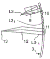
FIG. 13 is a view of the coupling-in section 10 according to another embodiment; and
fig. 14 is a sectional view of the spectacle lens 3 to explain the other embodiment.
Detailed Description
In the embodiment shown in fig. 1, the display device 1 according to the invention comprises a holder 2, said holder 2 being able to be fitted on the head of a user and being able to be formed, for example, in the manner of a conventional spectacle frame; and a first light-guiding element 3 and a second light-guiding element 4 in the form of a first and a second spectacle lens, which are fixedly secured to the holder 2.
The two ophthalmic lenses 3, 4 comprise a curved front side 5, 5 'and a curved rear side 6, 6', respectively.
In fig. 2, in a schematic top view, a first ophthalmic lens 3 is illustrated cooperating with other components of the display device 1 according to the invention. The ophthalmic lens has a thickness of 1.5mm, wherein the radius of curvature of each of the front side 5 and the back side 6 is 100 mm. PMMA from Zeomex is used as material for the ophthalmic lens 3. The display device 1 further comprises a control unit 7, an image generation module 8, which here for example comprises a two-dimensional light modulator in the form of an OLED module, and an additional optical system 9 arranged between the image generation module 8 and the first ophthalmic lens 3. An additional optical system 9 is optionally provided.
In the edge region 15 of the first spectacle lens 3, a diffractive coupling-in section 10 is formed and, spaced apart therefrom, a diffractive coupling-out section 11 is formed in the central region 16 of the spectacle lens 3. Furthermore, in fig. 2, the pupil 12 and the retina 12 of an eye of a user wearing the display device 1 according to the invention are schematically depicted. In addition, beam paths of three light beams L1, L2, and L3 from the image generation module 8 to the retina 13 are schematically drawn.
The light beams L1-L3 emitted by the imaging system 8 (each light beam L1-L3 emerging from one of several pixels of the two-dimensional light modulator of the image generation module 8) are guided by the additional optical system 9 onto the rear side 6 of the first ophthalmic lens 3, enter the ophthalmic lens 3 via the rear side 6 and hit the coupling-in section 10. At the incoupling section 10, the light beams L1-L3 each split into four first sub-beams L1, which are offset or spaced apart from each other in the x-direction (first direction)1、L12、L13And L14As schematically illustrated in fig. 3. For simplicity of illustration, in fig. 3, only the light beam L1 and the four first sub-light beams L1 are shown1-L14And in fig. 4 and 5, the front side 5 and the rear side 6 are illustrated as flat, rather than curved. In addition, in the following description, only the light beam L1 is substantially mentioned. Of course, the description also refers to the other light beams L2, L3 of the image generation module 8.
First sub-beam L11-L14The coupled-in sections 10 are further deflected in a second direction (y-direction) and coupled into the ophthalmic lens 3 such that they hit the rear side 6 at an angle at which total internal reflection occurs. Thus, the first sub-beam L11-L14Guided at the rear side 6 and the front side 5 to the coupling-out section 11 by means of total internal reflection, which results in a first sub-beam L11-L14Via the coupling-out of the rear side 6, the user is enabled to perceive the image generated by the imaging system 8 as a virtual image. The coupling-out takes place in such a way that the first sub-beam L11-L14Are respectively divided into a plurality of second sub-beams L111-L114And are coupled out spaced apart from each other in the y-direction, as described in more detail below. The additional optical system 9 in cooperation with the first spectacle lens 3 and the coupling-in section 10 and the coupling-out section 11 thus form an imaging optical system 14 which images the image generated by the image generation module 8 as a virtual image for the user.
Due to the sub-beam L11-L14Almost overlap each other in the y direction, and therefore the exit pupil of the imaging optical system 14 is enlarged in the x direction. Forming a second sub-beam L111-L114This splitting of the second sub-beam and the coupling-out of the second sub-beam lead to an enlargement of the exit pupil of the imaging optical system 14 in the y-direction. In order for the user to perceive the virtual image, the pupil 12 of the user's eye must be located in the exit pupil of the imaging optical system 14. Since the exit pupil is enlarged in the x and y directions according to the invention, the display device 1 according to the invention can be made, for example, with different eye distances (which results in different positions of the respective pupil 12 in the y direction) For different users.
First, in connection with fig. 3 to 5, the construction of the incoupling section 10 is described in more detail, which generates a first partial light beam L1 spaced apart in the x-direction1-L14And thus makes it possible to enlarge the exit pupil in the x-direction. For this purpose, the coupling-in section 10 comprises a first plate-like section 20 and a second plate-like section 21 spaced apart therefrom, wherein between the two plate- like sections 20 and 21 an air gap 22 is provided.
The first plate-like section 20 comprises a first side 23 facing away from the air gap 22 and a second side 24 facing towards the second plate-like section 21. The second plate-like section 21 comprises a first side 25 facing towards the first plate-like section 20 and a second side 26 facing away from the first plate-like section 20.
The light beams L1-L3 enter the first plate-like section 20 via the first side 23 of the first plate-like section 20 and travel up to the second side 24. In this region, a first reflection grating 27 is formed which diffracts (first order diffraction) the light beams L1-L3 (hereinafter, for simplicity, only the light beam L1) vertically or in the x direction. The vertically diffracted beam travels towards the first side 23, which in this region comprises a second reflection grating 28 formed such that a portion (first sub-beam L1)1) Diffract in a direction towards the second side 24 and hit said second side 24 at an angle (here 90 °) at which it leaves the first plate-like section 20, travel through said air gap 22, enter said second plate-like section 21 via its first side 25 and hit a third reflection grating 29 formed at the second side 26. The third reflection grating 29 reflects the first sub-beam L1 in the horizontal direction (y-direction)1So that it is guided to the out-coupling section 11 by total reflection at the rear side 6 and the front side 5. In the illustration of fig. 3 and 5, the distance between the coupling-in section 10 and the coupling-out section 11 is significantly shortened in the illustration.
In the first hit on the second reflection grating 28, the undiffracted part of the light beam L1 and thus the part of the zero-order diffraction L1' is reflected towards the second side 24 of the first plate-like section 20 and, in turn, is reflected, for example, byThe lower second side 24 reflects where the secondary portion L1' hits the second reflection grating 28 again. The diffracted portion L12 travels through the second side 24, the air gap 22, the first side 25, and hits the third reflection grating 29 at the second side 26. The incident area of the first sub-beam L12 deviates in the x-direction with respect to the incident area of the first sub-beam L11, as can be seen in fig. 3 and 4. The first sub-beam L12 is then diverted in the horizontal direction by the third reflection grating 29 and guided to the out-coupling section 11 due to total internal reflection at the rear side 6 and the front side 5. As shown in fig. 3 and 4, which illustrate four first sub-beams L11-L14Their guide paths are superposed on each other in the x-direction.
These first sub-beams L11-L14Are subsequently coupled out once or several times, are offset with respect to one another in the y-direction by means of the coupling-out sections 11, as shown by way of example in fig. 5 only for the first sub-beam L11Is selected to be the lowest guide path of the guide paths of (1). The first sub-beam L11Is divided into four second sub-beams L111、L112、L113、L114Which are coupled out at a distance from one another in the y-direction.
In the following, for simplicity of explanation, only light beams L1-L3 (actually meaning the respective first and second sub-beams) are generally described.
The coupling-out section 11 is formed here such that it comprises a fourth reflection grating 30 which effects the second sub-beam L1 via first-order diffraction of the fourth grating 3011-L114Is coupled out. The part which is not coupled out is reflected by the fourth grating 30 to the rear side 6 of the first spectacle lens 3 as zeroth-order diffraction, so that the respective light beam L1-L3 and/or a part of the respective light beam L1-L3 hits the fourth grating 30 again after total internal reflection at the rear side 6 in a region spaced apart from the region which was hit first in the y-direction. Then, only a part of these light beams L1-L3 or beam parts is coupled out (first order diffraction, second sub-beam L1)12). The remaining part is then reflected towards the back side 6 (zero order diffraction) such thatThe light beams L1-L3 or the light pillar of the light beam portions then hit the fourth grating 30 after total internal reflection at the rear side 6. Here, the fourth grating 30 is designed such that it performs a maximum of five out-couplings (only four out-couplings are labeled in fig. 3-5 for simplicity in the description so far). Thus, with each coupling-out, the corresponding first sub-beam L11-L14Second sub-beam L111-L114Are generated, wherein the second sub-beams are offset with respect to each other in the y-direction. Here, the fourth grating 30 is designed such that the first sub-beam L11-L14Respectively, partially overlap in the plane of the exit pupil. Thus, the exit pupil of the imaging optical system 14 in the y-direction or the eye-box/eye-movement range of the imaging optical system 14 in the y-direction (i.e. the region in which the user's eye can move and the user can always perceive the coupled-out image) is larger than the pupil of the eye, wherein at the same time a large field of view occurs in the y-direction.
In the embodiments described herein, the field of view provided to the user has a size of 12 ° × 4 ° and a diameter of the eye-box of 7mm, where the pupil of the eye is assumed to have a diameter of 3 mm.
In fig. 6a-6e, a single out-coupling of an upper field angle of +6 ° of the provided field of view is schematically illustrated. The upper field angle corresponds on the imaging system 8 (or the two-dimensional light modulator of the image generation module) to a y-value of 2mm opposite the center of said imaging system 8. In fig. 6a, the first sub-beam L1 is shown1A first coupling-out resulting during a first hit on the fourth grating 30, and the resulting first sub-beam L11Second sub-beam L111. Subsequently, in fig. 6b-6e, the resulting second to fifth outcoupling during the second to fifth hits and the resulting second sub-beam or second partial beam L1 are illustrated12、L113、L114、L115。
As can be gathered from fig. 6a-6e, the major part of the light that can be perceived by the user originates from the first secondary out-coupling (second sub-beam L1)11). Small partDerived from the second coupling-out (second sub-beam L1)12). The light outcoupled from the third to fifth times may no longer be perceived by the user. Thus, the fourth grating (or out-coupling grating) 30 is designed such that the first sub-beam L11Are coupled out as completely as possible via the first and second secondary coupling-out. The outcoupling grating 30 is no longer designed for this purpose, since the third to fifth outcoupling may not hit the pupil of the eye 12. For example, in a usual optimization calculation for determining the necessary grating parameters, the corresponding second sub-beam L1 is not taken into account13-L115。
In fig. 7, the plane for the pupil of the eye 12 illustrates the first sub-beam L11Of the five coupled-out second sub-beams L111-L115Wherein the second sub-beam L1 is not actually generated and is only described for illustrating the present invention13-L115Drawn in dashed lines.
In fig. 8a-8e, a first light beam L2 for a central field angle is illustrated1In which the angle of incidence is perpendicular to the pupil of the eye 12, which corresponds to a y-value of 0mm on the imaging system and thus to the center of the imaging system 8 in the same way as in fig. 6a-6 e. In fig. 9, in the same manner as in fig. 7, the light beam is illustrated with respect to five second sub-beams L211、L212、L213、L214、L215The location of the pupil of the eye 12. As can be seen from the illustrations according to FIGS. 8a-8e and 9, the first sub-beam L21Third time out-coupling L213Most of the light is delivered to the observer. Second and fourth subcoupling L212And L214Contributing only a small part. The coupling-out grating 30 is thus designed such that the first sub-beam L2 occurs during the second to fourth hits on the fourth coupling-out grating 301Is coupled out.
In fig. 10a-10e, in the same way as in fig. 6a-6e, a view angle for-6 deg. (first sub-beam L3) at the pupil of the eye 12 is shown1) Is coupled out of the optical fiber and is,which corresponds to a y-value of-2 mm originating from the center on the two-dimensional light modulator of the image generation module 8. In fig. 11, in turn, the partial light beam L3 is illustrated with respect to the coupling-out, which is shown in top view according to fig. 711、L312、L313、L314、L315In terms of the location of the pupil of the eye 12. As can be seen from fig. 10a-10e and fig. 11, the major part of the light originates from the fifth outcoupling L315. Fourth time out-coupling L314And also contributes to a small extent. The coupling-out grating 30 is thus designed such that the first sub-beam L3 occurs during the fourth and fifth hit1Is coupled out.
In fig. 12, all second sub-beams L1 of the light beam L1 are schematically shown in the plane of the pupil of the eye or in the exit pupil of the imaging optical system 1411-L115、L121-L125、L131-L135And L141-L145. This shows the size or enlargement of the exit pupil achieved in the x-direction and the y-direction.
The out-coupling grating 30 preferably has an optimal grating structure for each out-coupling, wherein the grating structure is preferably designed such that congruence is achieved for the field angle served by several adjacent out-couplings. This means that the same location on the retina 13 is hit within the frame of the resolution of the eye (<1 min). It can also be said that the same main beam angle exists for the adjacent out-coupling (adjacent second sub-beams) for one field angle. This can be achieved, for example, because both the third grating 29 and the fourth grating 30 are designed for imaging and are optimized simultaneously in conjunction with the specific shape of the first spectacle lens 3, so that, on the one hand, the requirements of the modulation transfer function are met and, on the other hand, the described congruent is achieved. In general, the field angle or field point is served by at most three out-coupling in the y-direction, and as a result congruence is thus achieved for at most three adjacent out-coupling which can be easily achieved in practice.
If the third grating 29 and the fourth grating 30 are designed for imaging, this is possibleCompensating for the beam distortion caused by the first sub-beam L11-L31Imaging errors caused by oblique incidence on the fourth grating 30, such as astigmatism and oblique spherical aberration. Oblique incidence on the fourth grating 30 inevitably exists because of the first sub-beam L11-L31Guided to the fourth grating 30 by total internal reflection at the front side 5 and the back side 6 of the first spectacle lens 3.
The additional optical system 9 is designed such that the light beams L1-L3 hit the spectacle lens 3 or the coupling-in section 10 as collimated light beams. However, the additional optical system 9 may also be dispensed with. In this case, the coupling-in section 10 can, for example, take over the collimation function.
The entrance pupil of the imaging optical system 14 is preferably placed on or near the third grating 29, so that the light beam of the light column or light beams L1-L3 of all pixels of the two-dimensional light modulator of the image generation module 8 achieves as little spot enlargement as possible on the third grating 29.
Furthermore, the third grating 29 and the fourth grating 30 preferably have approximately the same center frequency in order to minimize the spectral dependence. In addition, the third grating 29 and the fourth grating 30 may have a base dispersion of approximately the same size, which is achieved by: on the one hand, light is diffracted out of the spectacle lens 3 again in the direction of the eye and, on the other hand, the color-dependent diffraction angles are substantially compensated for one another. All colors after leaving the spectacle lens 3 run in the same direction as much as possible, respectively, as a result of which a significant spreading of the colors can be prevented. To achieve this congruence, the stack of the respective adjacent coupling-out of the respective second sub-beams towards the desired target image position can be inserted as an evaluation parameter into the normally optimized merit function, i.e. for each target image position, optimization in terms of image quality (modulation transfer function, spot size, etc.) and overlay accuracy is carried out for the different possible coupling-out branches at which light can reach the target image position. The degrees of freedom here are the positions of the laser sources used in the illumination of the hologram to generate the third grating 29 and the fourth grating 30. Due to the relatively small thickness of the spectacle lens, the difference in the interference state of the wave caused by total reflection at the curved spectacle lens 3, 4 is relatively small with respect to the adjacent out-coupling and can therefore be optimized very well.
The features and design of the third grating 29 and the fourth grating 30 may be implemented in the same way as in the case of the first grating 27 and the second grating 28. The two gratings 27 and 28 may also be designed such that, for example, the diffraction angles dependent or dependent on the color are approximately compensated. The two gratings 27 and 28 can also be optimized together.
In addition, additional corrective optical systems (e.g., lenses, mirrors, computer generated holograms, etc.) may also be incorporated into the illumination configuration of the hologram to achieve additional improvements in performance.
In order to achieve as uniform a field distribution as possible in terms of intensity, the diffraction efficiency of the fourth grating 30 and/or the second grating 28 may, for example, increase with increasing coupling-out. This may be achieved by a suitable distribution of the profile depths of the respective gratings 30, 28. Thus, in the first out-coupling only a relatively small part of the possible diffraction efficiency is used, and the diffraction efficiency increases from the first out-coupling to the last out-coupling.
Furthermore, an index/gradient filter (e.g., a variable gray filter) may be disposed proximate to the image generation module 8. Suitable position-dependent radiation characteristics of the imaging system can also be provided for intensity.
In order to obtain as good a result as possible for white light, the third grating 29 and the fourth grating 30 may each be designed as a superposition of, for example, three respective gratings, whose center frequencies are designed such that the beams of the corresponding intermediate wavelengths are superposed. Here, a pair of gratings may for example be adapted for red, green and blue light, respectively. The same applies to the first beam 27 and the second grating 28.
Further improvements in the efficiency characteristics can be achieved by designing the third grating 29 and the fourth grating 30 and/or the first grating 27 and the second grating 28, respectively, as reflector gratings.
The outcoupling section 11 is designed such that a user can perceive a virtual image of the outcoupling superimposed on the surrounding environment. Furthermore, the third grating 29 and the fourth grating 30 may be formed on the front side 5, respectively, as reflection gratings. The two plate-shaped sections 20, 21 can be formed, for example, by creating slits in the edge region 15 for forming the air gap 22.
In the display device according to the invention, the first sub-beam thus hits the fourth grating 30 at most n times, depending on the position of the associated pixel of the imaging system, where n is an integer greater than or equal to 3. In an embodiment, n is equal to 5 as described herein. In addition, each first sub-beam is coupled out, 1 to m consecutive hits on the fourth grating 30, depending on the position of the associated pixel, where m is an integer greater than or equal to 1 and less than n. In the embodiment described herein, m is 2 for the first sub-beam of the light beam L1, 3 for the first sub-beam of the light beam L2, and 2 for the first sub-beam of the light beam L3. The outcoupling of the respective first sub-beams starts at the latest at the (n-m +1) th hit on the fourth grating 30. In the first sub-beam L11In the case of (1), the out-coupling starts in the first hit on the fourth grating 30, in the first sub-beam L21In the case of (1), the out-coupling starts with the second hit on the fourth grating 30 and in the first sub-beam L31In the case of (1), the out-coupling starts with the fourth hit on the fourth grating 30.
In addition, in the described embodiment it is the case that two to three out-coupling or diffractive out-coupling are required for the required output of the respective first sub-beam. However, it is also possible that only one diffractive outcoupling is required for at least one of the first sub-beams L1-L3.
Since the third grating 29 must strongly diffract the first sub-beam L11-L14So that the first sub-beam L11-L14Subsequently guided by total internal reflection in the spectacle lens 3, a grating frequency of approximately 1700-. In the case of green light, for example, a grating frequency of about 2000 lines/mm is required, in the case of red light, for example, a grating frequency of about 1700 lines/mm is required, and in the case of blue light, for example, about 23 lines/mm is requiredGrating frequency of 00 lines/mm. The same applies to the fourth grating 30, which must direct the first partial beam L1 directed towards it by means of total reflection1-L14Coupled out towards the eyes of the user. It is therefore preferred to manufacture the third grating 29 and the fourth grating 30 by holographic illumination with plane waves and/or spherical waves. The location of the laser source used in the illumination of the hologram is a possible correction factor that can be used to correct the modulation transfer function and the isotacticity. In order to achieve the improvement, in particular, a deformed wavefront can also be used. During illumination of the grating, special optical systems or computer-generated holograms may be introduced into the illumination beam path to further improve overall performance.
In the exemplary embodiments described so far, the coupling-in section 10 and the coupling-out section 11 are each formed as diffractive. However, it is also possible to form the coupling-in section 10 and the coupling-out section 11 as non-diffractive sections, respectively. For example, the in-coupling section 10 and the out-coupling section 11 may be formed as partially or partially reflective sections, respectively.
In fig. 13, the incoupling section 10 is schematically illustrated in the same way as in fig. 4, wherein like elements are denoted by like reference numerals and in the description thereof reference is made to what is described above. In contrast to the exemplary embodiment according to fig. 4, in the case of the coupling-in section 10 according to fig. 13, no grating is provided, but instead a reflective surface element 31 is provided on the second side 24 of the first plate-like section, a partially reflective surface element 32 is provided on the first side 23 of the first plate-like section, and a reflective surface element 33 is provided on the second side 26 of the second plate-like section 21.
The bins 31-33 are oriented such that a light beam L1 entering the first plate-like section 20 via the first side 23 is reflected towards the first side 23 and hits the first bin(s) 32. A portion of the light beam L1 is provided as a first sub-beam L11But is turned so that it runs through the second side 24, the first side 25 and hits the reflective surface element 33, which results in a turn in the y-direction. The part of light beam L1 that is not reflected at surface element 32 travels through surface element 32 and strikes first side 23, where it faces towardTotal internal reflection occurs in the direction of the second side 24, with the result that this portion L1' again travels through partially reflective surface element 32 and then is turned at the second side 24 by total internal reflection towards the first side 23 and thus again hits said partially reflective surface element 32. In the same way, a beam splitting then takes place there, with the result that the light beam L1 is split into several sub-beams L11-L14They are coupled into the spectacle lens 3 such that they are guided by total internal reflection at the rear side 6 and the front side 5 to the coupling-out section 11.
The partially reflective surface elements are connected by surface element 34. They may preferably be transparent or partially transparent, as a result of which the light beam which is completely reflected at the first side 32 can also travel through the surface element 34.
As can be gathered from the illustration in fig. 14, the coupling-out section 11 comprises several partially reflective surface elements 35, which are connected by surface elements 36, the surface elements 36 preferably being transparent or partially reflective.
As can be gathered from the representation in fig. 14, the partially reflective surface element 35 acts as a beam splitter, as a result of which the first partial light beam L1 reflected in each case is formed1Is taken as the second sub-beam L111-L114Out-coupling and guiding the projected part after another total reflection at the front side 5 and the back side 6 into a further out-coupling (offset in y-direction).
Of course, the described embodiments can also be combined with one another. Thus, for example, the bins 31, 32 described in connection with fig. 13 may be formed at the first plate-like section 20, while the third grating 29 is arranged at the second plate-like section 21 and the fourth grating 30 is arranged in the out-coupling section 10. Furthermore, it is also possible to provide the first and second gratings 27, 28 at the first plate-like section and the corresponding bins 33, 35 at the second plate-like section 21 and in the coupling-out section 11.
The five coupled outputs described are intended to be examples only. Of course, fewer (but at least three) or more coupled outputs may be provided. With more coupled-out, a larger field of view may be provided.
In addition, the display device according to the present invention has been described so far only for one spectacle lens (left spectacle lens 3). The display device according to the invention may be formed such that the additional information item (image of the imaging system 8) is generated via only one spectacle lens (e.g. the left spectacle lens) and reflected into the field of view of the user. Of course, it is also possible to form two ophthalmic lenses, as a result of which an additional item of information can be reflected to both eyes of the user. In this case, these information items can also be reflected such that a three-dimensional image impression of the reflected information is formed for the user.
The ophthalmic lenses 3, 4 may be ophthalmic lenses for correcting visual defects. However, they need not be ophthalmic lenses; they may also have no optical correction effect on visual defects. The display device 1 according to the invention may be formed as sports glasses, sunglasses and/or eyes for correcting visual defects.
The spectacle lenses 3, 4 and in particular the left spectacle lens 3 are described together with the display device according to the invention, merely as an example. The spectacle lenses 3, 4, or at least the left side spectacle lens 3, are individually formed as spectacle lenses 3, 4 according to the invention, respectively. The left spectacle lens 3 according to the invention can naturally also be formed as a right spectacle lens.
Claims (3)
1. An eyeglass lens for a display device (1) that can be fitted to the head of a user and that generates an image,
the ophthalmic lens having a front side (5) and a back side (6), wherein the front side (5) and/or the back side (6) is curved,
and, when the spectacle lenses (3, 4) are viewed in plan view, having a coupling-in section (10) in the edge region (15) of the spectacle lenses (3, 4) and a coupling-out section (11) in the central region (16) of the spectacle lenses (3, 4),
wherein the spectacle lens (3, 4) is adapted to couple in light beams (L1, L2, L3) of pixels of the generated image into the spectacle lens (3, 4) via the coupling-in section (10), to guide the light beams in the spectacle lens (3, 4) to the coupling-out section (11) and to couple out the light beams from the spectacle lens (3, 4) via the coupling-out section (11),
wherein during coupling-in, the coupling-in section (10) splits each of at least one of the light beams (L1) into several first sub-beams (L1)1,L12,L13,L14) And the first partial beams are coupled into the spectacle lenses (3, 4) in such a way that they deviate from one another in a first direction, so that the first partial beams (L1)1-L14) In the spectacle lens (3, 4) is guided in a second direction transverse to the first direction to a coupling-out section (11),
and wherein during outcoupling, the outcoupling section (11) couples at least one of the first sub-beams (L1) of the number of first sub-beams1) Into a number of second sub-beams (L1)11,L112,L113,L114) And coupling out the second sub-beams from the ophthalmic lens offset from each other in a second direction;
wherein the coupling-in section (10) and the coupling-out section (11) comprise several partially reflective surface elements (32, 35) for causing the formation of the first and second sub-beams (L1) by reflection and transmission1-L14;L111-L114) The beam splitting of (a) is performed,
wherein the coupling-in section (10) comprises a first plate-like section (20) in the edge region (15) and a second plate-like section (21) in the edge region (15),
wherein the coupling-in section (10) comprises a partially reflective surface element (32) arranged at a first side (23) of the first plate-like section (20) and a reflective surface element (33) arranged at a second side (26) of the second plate-like section (21),
wherein a first side (23) of the first plate-like section (20) is flush with a rear side (6) of the ophthalmic lens (3, 4) and a second side (26) of the second plate-like section (21) is flush with a front side (5) of the ophthalmic lens (3, 4); and is
Wherein the coupling-in section (10) comprises an air gap (22) between the first plate-like section (20) and the second plate-like section (21).
2. The ophthalmic lens according to claim 1, wherein the coupling-in section (10) comprises a reflective surface element (31) at the second side (24) of the first plate-like section (20),
wherein the in-coupling section (10) splits at least one light beam (L1) such that the at least one light beam (L1) entering the first plate-like section (20) via the first side (23) of the first plate-like section (20) is reflected back by the reflective surface element (31) towards the first side (23) of the first plate-like section (20) and hits at least one partially reflective surface element (32), wherein:
a first part of the at least one light beam (L1) being a first sub-light beam (L1)1) Is deflected such that it runs through the second side (24) of the first plate-like section (20), the air gap (22), the first side (25) of the second plate-like section (21) and hits at least one reflective surface element (33), which produces a deflection in a second direction, and
a second portion (L1') of the at least one light beam (L1) that is not reflected at the at least one partially reflective surface element (32) travels through the at least one partially reflective surface element (32) and hits the first side (23) of the first plate-like section (20), total internal reflection occurs at the first side (23) of the first plate-like section (20) in a direction towards the second side (24) of the first plate-like section (20), with the result that the second portion (L1') travels again through the at least one partially reflective surface element (32), is then turned by total internal reflection at the second side (24) of the first plate-like section (20) towards the first side (23) of the first plate-like section (20) and thus hits the partially reflective surface element (32) again, so that beam splitting is then generated there.
3. A display device has:
a holder (2) that can be fitted on the head of a user;
an image generation module (8) fixed to the holder (2), the image generation module generating an image; and
imaging optical system (14) fixed to the holder (2), comprising an ophthalmic lens according to one of claims 1 to 2, and imaging the generated image when the holder (2) is fitted to the head, so that the user can perceive it as a virtual image.
Applications Claiming Priority (3)
| Application Number | Priority Date | Filing Date | Title |
|---|---|---|---|
| DE102013219625.3A DE102013219625B3 (en) | 2013-09-27 | 2013-09-27 | Spectacle lens for a display device which can be placed on the head of a user and generates an image, and a display device with such a spectacle lens |
| DE102013219625.3 | 2013-09-27 | ||
| CN201480053197.3A CN105579888B (en) | 2013-09-27 | 2014-09-25 | Spectacle lens for display device capable of being mounted on user's head and generating images, and display device provided with spectacle lens |
Related Parent Applications (1)
| Application Number | Title | Priority Date | Filing Date |
|---|---|---|---|
| CN201480053197.3A Division CN105579888B (en) | 2013-09-27 | 2014-09-25 | Spectacle lens for display device capable of being mounted on user's head and generating images, and display device provided with spectacle lens |
Publications (2)
| Publication Number | Publication Date |
|---|---|
| CN109031663A CN109031663A (en) | 2018-12-18 |
| CN109031663B true CN109031663B (en) | 2022-01-25 |
Family
ID=51627289
Family Applications (2)
| Application Number | Title | Priority Date | Filing Date |
|---|---|---|---|
| CN201480053197.3A Active CN105579888B (en) | 2013-09-27 | 2014-09-25 | Spectacle lens for display device capable of being mounted on user's head and generating images, and display device provided with spectacle lens |
| CN201810824275.5A Active CN109031663B (en) | 2013-09-27 | 2014-09-25 | Spectacle lens for display device which can be mounted on the head of a user and generates an image, and display device provided with spectacle lens |
Family Applications Before (1)
| Application Number | Title | Priority Date | Filing Date |
|---|---|---|---|
| CN201480053197.3A Active CN105579888B (en) | 2013-09-27 | 2014-09-25 | Spectacle lens for display device capable of being mounted on user's head and generating images, and display device provided with spectacle lens |
Country Status (7)
| Country | Link |
|---|---|
| US (2) | US10656420B2 (en) |
| EP (2) | EP3049853B1 (en) |
| JP (1) | JP6453861B2 (en) |
| KR (1) | KR102266506B1 (en) |
| CN (2) | CN105579888B (en) |
| DE (1) | DE102013219625B3 (en) |
| WO (1) | WO2015044302A1 (en) |
Families Citing this family (52)
| Publication number | Priority date | Publication date | Assignee | Title |
|---|---|---|---|---|
| US10073264B2 (en) | 2007-08-03 | 2018-09-11 | Lumus Ltd. | Substrate-guide optical device |
| US10261321B2 (en) | 2005-11-08 | 2019-04-16 | Lumus Ltd. | Polarizing optical system |
| IL232197B (en) | 2014-04-23 | 2018-04-30 | Lumus Ltd | Compact head-mounted display system |
| IL235642B (en) | 2014-11-11 | 2021-08-31 | Lumus Ltd | Compact head-mounted display system protected by a hyperfine structure |
| AU2016333970B2 (en) * | 2015-10-05 | 2021-08-05 | Magic Leap, Inc. | Microlens collimator for scanning optical fiber in virtual/augmented reality system |
| WO2017127494A1 (en) | 2016-01-22 | 2017-07-27 | Corning Incorporated | Wide field personal display |
| EP3469405A1 (en) | 2016-06-09 | 2019-04-17 | 3M Innovative Properties Company | Display system and light guide |
| CN107632406A (en) * | 2016-07-18 | 2018-01-26 | 北京灵犀微光科技有限公司 | Holographic waveguide, augmented reality display system and display method |
| DE102016115938A1 (en) | 2016-08-26 | 2018-03-01 | Carl Zeiss Jena Gmbh | Waveguides and devices for data input |
| JP6848310B2 (en) * | 2016-09-30 | 2021-03-24 | セイコーエプソン株式会社 | Virtual image display device |
| US10466479B2 (en) * | 2016-10-07 | 2019-11-05 | Coretronic Corporation | Head-mounted display apparatus and optical system |
| EP3540484B1 (en) | 2016-10-09 | 2020-11-04 | Lumus Ltd. | Aperture multiplier using a rectangular waveguide |
| CN113031165B (en) | 2016-11-08 | 2023-06-02 | 鲁姆斯有限公司 | Light guide device, optical component thereof and corresponding production method |
| IL312713A (en) * | 2016-11-18 | 2024-07-01 | Magic Leap Inc | A waveguide light multiplexer using crossed gratings |
| JP7232182B2 (en) * | 2016-11-30 | 2023-03-02 | マジック リープ, インコーポレイテッド | Method and system for high resolution digitized display |
| CN108333752B (en) * | 2017-01-19 | 2020-12-29 | 中强光电股份有限公司 | Optical system and head-mounted display device |
| KR102751421B1 (en) * | 2017-02-22 | 2025-01-07 | 루머스 리미티드 | Light guide optical assembly |
| CN117572644A (en) | 2017-03-22 | 2024-02-20 | 鲁姆斯有限公司 | Methods and optical systems for producing light guide optical elements |
| IL251645B (en) | 2017-04-06 | 2018-08-30 | Lumus Ltd | Light-guide optical element and method of its manufacture |
| CN110678802B (en) * | 2017-05-16 | 2021-12-03 | 奇跃公司 | System and method for mixed reality |
| US10976551B2 (en) | 2017-08-30 | 2021-04-13 | Corning Incorporated | Wide field personal display device |
| US10551544B2 (en) | 2018-01-21 | 2020-02-04 | Lumus Ltd. | Light-guide optical element with multiple-axis internal aperture expansion |
| FI129387B (en) * | 2018-03-28 | 2022-01-31 | Dispelix Oy | Waveguide element |
| WO2019224764A1 (en) | 2018-05-23 | 2019-11-28 | Lumus Ltd. | Optical system including light-guide optical element with partially-reflective internal surfaces |
| DE102019102614A1 (en) | 2019-02-01 | 2020-08-06 | Carl Zeiss Jena Gmbh | Screen with a transparent base |
| DE102019102608A1 (en) | 2019-02-01 | 2020-08-06 | Carl Zeiss Jena Gmbh | Functionalized waveguide for a detector system |
| DE102019102604A1 (en) * | 2019-02-01 | 2020-08-06 | Carl Zeiss Jena Gmbh | Functionalized waveguide for a detector system |
| WO2020174433A1 (en) | 2019-02-28 | 2020-09-03 | Lumus Ltd. | Compact collimated image projector |
| DE102019108678A1 (en) | 2019-04-03 | 2020-10-08 | Carl Zeiss Ag | Device for supplying energy to an active eye implant |
| DE102019108679A1 (en) | 2019-04-03 | 2020-10-08 | Carl Zeiss Ag | Devices for supplying energy to an active eye implant |
| DE102019108677A1 (en) * | 2019-04-03 | 2020-10-08 | Carl Zeiss Jena Gmbh | Devices for generating light distributions with optical waveguides |
| TWI884885B (en) | 2019-04-15 | 2025-05-21 | 以色列商魯姆斯有限公司 | Method of fabricating a light-guide optical element |
| BR112021022229A2 (en) | 2019-06-27 | 2022-02-22 | Lumus Ltd | Device |
| JP7592326B2 (en) | 2019-07-18 | 2024-12-02 | ルムス エルティーディー. | Encapsulated Light Guide Optical Elements |
| JP7333721B2 (en) | 2019-07-29 | 2023-08-25 | 株式会社日立エルジーデータストレージ | Hologram light guide plate, head-mounted display |
| US11703689B2 (en) * | 2019-11-15 | 2023-07-18 | Samsung Electronics Co., Ltd. | Device for enlarging exit pupil area and display including the same |
| EP4042232B1 (en) | 2019-12-08 | 2025-02-19 | Lumus Ltd. | Optical systems with compact image projector |
| US11415805B2 (en) | 2019-12-30 | 2022-08-16 | Meta Platforms Technologies, Llc | Optical system and method for providing compressed eyebox |
| US12372799B2 (en) | 2020-05-12 | 2025-07-29 | Lumus Ltd. | Rotatable lightpipe |
| CN115885215A (en) | 2020-08-26 | 2023-03-31 | 鲁姆斯有限公司 | Color image generation using white light as a source |
| WO2022044019A1 (en) | 2020-08-30 | 2022-03-03 | Lumus Ltd. | Reflective slm image projector with intermediate image plane |
| CN116635773B (en) | 2021-03-01 | 2025-06-13 | 鲁姆斯有限公司 | Optical system with compact coupling from projector into waveguide |
| CN115236854B (en) * | 2021-04-22 | 2024-04-12 | 华为技术有限公司 | AR frame and AR glasses |
| US11822088B2 (en) | 2021-05-19 | 2023-11-21 | Lumus Ltd. | Active optical engine |
| CN117396792B (en) | 2021-07-04 | 2025-02-25 | 鲁姆斯有限公司 | Display with stacked light guide elements providing different portions of a field of view |
| EP4374204B1 (en) | 2021-08-23 | 2025-02-12 | Lumus Ltd. | Methods of fabrication of compound light-guide optical elements having embedded coupling-in reflectors |
| JP2024536392A (en) * | 2021-10-06 | 2024-10-04 | ヴィヴィッドキュー リミテッド | Eyebox targeting using image duplication combiner |
| CN114415288A (en) * | 2022-01-11 | 2022-04-29 | 北京耐德佳显示技术有限公司 | Waveguide optical module and near-to-eye display equipment |
| GB2608667B (en) * | 2022-03-04 | 2023-07-05 | Envisics Ltd | Light engine |
| EP4573404A4 (en) | 2022-08-18 | 2025-12-10 | Lumus Ltd | IMAGE PROJECTOR WITH POLARIZING CATADIOPTRIC COLLIMATOR |
| EP4439155A3 (en) * | 2022-09-06 | 2025-01-15 | HTC Corporation | Spatial and sequential stepped exposure methods for manufacturing diffracting elements of a waveguide device or an optical engine |
| EP4689483A1 (en) * | 2023-06-22 | 2026-02-11 | Google LLC | Augmented reality eyewear display using diffractive and reflective lightguides |
Citations (1)
| Publication number | Priority date | Publication date | Assignee | Title |
|---|---|---|---|---|
| CN101963703A (en) * | 2009-07-22 | 2011-02-02 | 索尼公司 | Image display device and optical device |
Family Cites Families (17)
| Publication number | Priority date | Publication date | Assignee | Title |
|---|---|---|---|---|
| US4711512A (en) * | 1985-07-12 | 1987-12-08 | Environmental Research Institute Of Michigan | Compact head-up display |
| ITTO20020625A1 (en) * | 2002-07-17 | 2004-01-19 | Fiat Ricerche | LIGHT GUIDE FOR "HEAD-MOUNTED" OR "HEAD-UP" TYPE DISPLAY DEVICES |
| WO2004109349A2 (en) * | 2003-06-10 | 2004-12-16 | Elop Electro-Optics Industries Ltd. | Method and system for displaying an informative image against a background image |
| JP4605152B2 (en) * | 2004-03-12 | 2011-01-05 | 株式会社ニコン | Image display optical system and image display apparatus |
| EP1748305A4 (en) * | 2004-05-17 | 2009-01-14 | Nikon Corp | Optical element, combiner optical system, and image display unit |
| WO2006025317A1 (en) * | 2004-08-31 | 2006-03-09 | Nikon Corporation | Light flux expanding optical system and imag display unit |
| US7206107B2 (en) * | 2004-12-13 | 2007-04-17 | Nokia Corporation | Method and system for beam expansion in a display device |
| EP1922579B1 (en) | 2005-09-07 | 2015-08-19 | BAE Systems PLC | A projection display with two plate-like, co-planar waveguides including gratings |
| US7616492B2 (en) * | 2005-10-04 | 2009-11-10 | Qimonda Ag | Evaluation circuit and evaluation method for the assessment of memory cell states |
| JP2007219106A (en) * | 2006-02-16 | 2007-08-30 | Konica Minolta Holdings Inc | Optical device for expanding diameter of luminous flux, video display device and head mount display |
| WO2008148927A1 (en) * | 2007-06-04 | 2008-12-11 | Nokia Corporation | A diffractive beam expander and a virtual display based on a diffractive beam expander |
| JP4450058B2 (en) * | 2007-11-29 | 2010-04-14 | ソニー株式会社 | Image display device |
| WO2009141332A1 (en) * | 2008-05-19 | 2009-11-26 | Interuniversitair Microelektronica Centrum Vzw (Imec) | Integrated photonics device |
| US8810913B2 (en) * | 2010-01-25 | 2014-08-19 | Bae Systems Plc | Projection display |
| DE102011007811B4 (en) * | 2011-04-20 | 2015-10-22 | Carl Zeiss Ag | display device |
| EP2751611B1 (en) * | 2011-08-29 | 2018-01-10 | Vuzix Corporation | Controllable waveguide for near-eye display applications |
| DE102012213685B4 (en) * | 2012-08-02 | 2020-12-24 | tooz technologies GmbH | Display device |
-
2013
- 2013-09-27 DE DE102013219625.3A patent/DE102013219625B3/en active Active
-
2014
- 2014-09-25 EP EP14777063.0A patent/EP3049853B1/en active Active
- 2014-09-25 EP EP23185884.6A patent/EP4270089A3/en active Pending
- 2014-09-25 CN CN201480053197.3A patent/CN105579888B/en active Active
- 2014-09-25 KR KR1020167008997A patent/KR102266506B1/en active Active
- 2014-09-25 JP JP2016518157A patent/JP6453861B2/en active Active
- 2014-09-25 US US15/025,205 patent/US10656420B2/en active Active
- 2014-09-25 WO PCT/EP2014/070557 patent/WO2015044302A1/en not_active Ceased
- 2014-09-25 CN CN201810824275.5A patent/CN109031663B/en active Active
-
2020
- 2020-04-14 US US16/848,783 patent/US11624918B2/en active Active
Patent Citations (1)
| Publication number | Priority date | Publication date | Assignee | Title |
|---|---|---|---|---|
| CN101963703A (en) * | 2009-07-22 | 2011-02-02 | 索尼公司 | Image display device and optical device |
Also Published As
| Publication number | Publication date |
|---|---|
| KR102266506B1 (en) | 2021-06-16 |
| CN109031663A (en) | 2018-12-18 |
| JP6453861B2 (en) | 2019-01-16 |
| KR20160062030A (en) | 2016-06-01 |
| US20160238844A1 (en) | 2016-08-18 |
| US11624918B2 (en) | 2023-04-11 |
| JP2016538580A (en) | 2016-12-08 |
| US10656420B2 (en) | 2020-05-19 |
| US20200241303A1 (en) | 2020-07-30 |
| EP4270089A3 (en) | 2023-12-06 |
| WO2015044302A1 (en) | 2015-04-02 |
| EP4270089A2 (en) | 2023-11-01 |
| CN105579888A (en) | 2016-05-11 |
| DE102013219625B3 (en) | 2015-01-22 |
| EP3049853A1 (en) | 2016-08-03 |
| EP3049853B1 (en) | 2023-07-19 |
| CN105579888B (en) | 2018-08-17 |
Similar Documents
| Publication | Publication Date | Title |
|---|---|---|
| CN109031663B (en) | Spectacle lens for display device which can be mounted on the head of a user and generates an image, and display device provided with spectacle lens | |
| JP7088997B2 (en) | Virtual reality, augmented reality, and mixed reality systems, including thick media, and related methods | |
| JP6196672B2 (en) | Display device | |
| CN108700751B (en) | A head-mounted display that uses spatial light modulators to generate holographic images | |
| CN108139593B (en) | Imaging light guide with reflective steering array | |
| JP6720315B2 (en) | Imaging light guide with reflective conversion array | |
| US11500143B2 (en) | Augmented reality imaging system | |
| US9442291B1 (en) | Segmented diffractive optical elements for a head wearable display | |
| US11536976B2 (en) | Augmented reality display | |
| JP6637881B2 (en) | A spectacle lens for a display device that generates an image and that can be mounted on the user's head, and a display device including the spectacle lens | |
| EP3518024A1 (en) | Display device | |
| CN110869834A (en) | Fixed focus image lightguide with subregional diffraction grating | |
| CN107076986B (en) | Imaging Optics and Data Glasses | |
| CN116209940A (en) | Optical system with cylindrical waveguide | |
| JP6565496B2 (en) | Light guide device and virtual image display device | |
| KR20220006023A (en) | Compact optical device for augmented reality using embedded collimator and negative refractive optical element | |
| JP2012098324A (en) | Light guide plate and virtual image display device having the same | |
| KR20140077378A (en) | Apparatus for head mounted display using holographic optical element lens | |
| CN120693561A (en) | Fixed focus image light guide system | |
| EP4630869A1 (en) | Waveguides for displays constructed from a combination of flat and curved surfaces using plural incouplers |
Legal Events
| Date | Code | Title | Description |
|---|---|---|---|
| PB01 | Publication | ||
| PB01 | Publication | ||
| SE01 | Entry into force of request for substantive examination | ||
| SE01 | Entry into force of request for substantive examination | ||
| GR01 | Patent grant | ||
| GR01 | Patent grant |