CN108995161B - Cooling structure of material pipe for thermosetting plastic injection molding - Google Patents
Cooling structure of material pipe for thermosetting plastic injection molding Download PDFInfo
- Publication number
- CN108995161B CN108995161B CN201810846381.3A CN201810846381A CN108995161B CN 108995161 B CN108995161 B CN 108995161B CN 201810846381 A CN201810846381 A CN 201810846381A CN 108995161 B CN108995161 B CN 108995161B
- Authority
- CN
- China
- Prior art keywords
- flow guide
- guide layer
- side wall
- layer
- cooling
- Prior art date
- Legal status (The legal status is an assumption and is not a legal conclusion. Google has not performed a legal analysis and makes no representation as to the accuracy of the status listed.)
- Active
Links
- 238000001816 cooling Methods 0.000 title claims abstract description 44
- 239000000463 material Substances 0.000 title claims abstract description 15
- 238000001746 injection moulding Methods 0.000 title claims abstract description 14
- 229920001187 thermosetting polymer Polymers 0.000 title claims abstract description 13
- XLYOFNOQVPJJNP-UHFFFAOYSA-N water Substances O XLYOFNOQVPJJNP-UHFFFAOYSA-N 0.000 claims abstract description 69
- QSHDDOUJBYECFT-UHFFFAOYSA-N mercury Chemical compound [Hg] QSHDDOUJBYECFT-UHFFFAOYSA-N 0.000 claims abstract description 12
- 229910052753 mercury Inorganic materials 0.000 claims abstract description 12
- 230000000149 penetrating effect Effects 0.000 claims abstract 2
- 230000008602 contraction Effects 0.000 abstract description 2
- 239000007921 spray Substances 0.000 abstract 1
- 239000004033 plastic Substances 0.000 description 4
- 229920003023 plastic Polymers 0.000 description 4
- 238000011084 recovery Methods 0.000 description 2
- 239000000243 solution Substances 0.000 description 2
- 241000220317 Rosa Species 0.000 description 1
- 238000010438 heat treatment Methods 0.000 description 1
- 239000002991 molded plastic Substances 0.000 description 1
- 238000013021 overheating Methods 0.000 description 1
- 239000002245 particle Substances 0.000 description 1
- 238000010008 shearing Methods 0.000 description 1
Images


Classifications
-
- B—PERFORMING OPERATIONS; TRANSPORTING
- B29—WORKING OF PLASTICS; WORKING OF SUBSTANCES IN A PLASTIC STATE IN GENERAL
- B29C—SHAPING OR JOINING OF PLASTICS; SHAPING OF MATERIAL IN A PLASTIC STATE, NOT OTHERWISE PROVIDED FOR; AFTER-TREATMENT OF THE SHAPED PRODUCTS, e.g. REPAIRING
- B29C45/00—Injection moulding, i.e. forcing the required volume of moulding material through a nozzle into a closed mould; Apparatus therefor
- B29C45/17—Component parts, details or accessories; Auxiliary operations
- B29C45/72—Heating or cooling
- B29C45/74—Heating or cooling of the injection unit
Landscapes
- Engineering & Computer Science (AREA)
- Manufacturing & Machinery (AREA)
- Mechanical Engineering (AREA)
- Moulds For Moulding Plastics Or The Like (AREA)
- Injection Moulding Of Plastics Or The Like (AREA)
Abstract
The invention discloses a cooling structure of a material pipe for thermosetting plastic injection molding, which comprises a pipe body and a flow guide layer, wherein a cavity is formed in the flow guide layer, the flow guide layer is sleeved on the outer side wall of the pipe body, two heat conduction plates are arranged between the flow guide layer and the pipe body in a penetrating manner, two symmetrically arranged high-pressure water tanks are fixedly connected to the outer side wall of the flow guide layer, a water outlet is formed in each high-pressure water tank, two symmetrically arranged fixed plates are fixedly connected to the side wall of the flow guide layer, which is far away from the high-pressure water tanks, and a sliding groove is formed in each fixed plate. The invention controls the inflow and the stop of water in the high-pressure water tank through the property of mercury expansion with heat and contraction with cold, is convenient to operate, sprays water into the cooling layer through the holes to cool the pipe body, is thorough in treatment, controls the water to flow into the collection cavity through the piston with the three-way structure, and is convenient to recover.
Description
Technical Field
The invention relates to the field of injection molding, in particular to a cooling structure of a material pipe for thermosetting plastic injection molding.
Background
In the injection molding process, the injection molding machine often needs to heat the material pipe at high temperature, so that plastic particles in the material pipe enter a molten state under the action of external heat and screw shearing heat, and molten plastic is injected and fills a mold cavity under the condition that high pressure is applied to the interior of the material pipe, so that various plastic products are manufactured.
The material pipe is easy to cause problems due to overheating, but the cooling of the material pipe cannot be effectively treated.
Disclosure of Invention
The invention aims to solve the problems in the background art and provides a cooling structure of a material pipe for thermosetting plastic injection molding.
In order to achieve the purpose, the invention adopts the following technical scheme:
the utility model provides a thermosetting plastics are moulded plastics and are used cooling structure of material pipe, includes body and the inside water conservancy diversion layer of seting up the cavity, water conservancy diversion layer cover is established on the lateral wall of body, it is provided with two heat-conducting plates to link up jointly between water conservancy diversion layer and the body, the high-pressure water tank that two symmetries of fixedly connected with set up on the lateral wall of water conservancy diversion layer, every all be equipped with the delivery port on the high-pressure water tank, the fixed plate that two symmetries of fixedly connected with set up on the lateral wall of high-pressure water tank were kept away from on the water conservancy diversion layer.
Preferably, every the equal fixedly connected with telescopic link of last lateral wall of heat-conducting plate, every all annotate mercury in the telescopic link.
Preferably, each telescopic link is fixedly connected with an L-shaped rod at one end far away from the heat conducting plate, one end of each L-shaped rod is inserted into the sliding groove and is fixedly connected with a pulley matched with the sliding groove in size, two water inlets communicated with the water outlets are formed in the outer side wall of the flow guide layer, a sliding groove is formed in each water inlet, and one end, far away from the pulley, of each L-shaped rod is inserted into the sliding groove.
Preferably, a plurality of holes are formed in the inner wall of the flow guide layer, each hole is located below the heat conduction plate, an annular conveying plate which is obliquely arranged is fixedly connected to the side wall of the opposite side of the flow guide layer, and the annular conveying plate is located below the holes.
Preferably, the outer side wall of the pipe body is fixedly connected with a cooling layer with a cooling cavity arranged inside, the flow guide layer is communicated with the cooling layer through a hole, and the cooling layer is positioned below the pipe body.
Preferably, a protruding end is arranged on the lower side wall of the cooling layer, a collecting cavity is arranged below the cooling layer, a piston is installed on the lower side wall of the protruding end, the piston is of a three-way structure, and two ways of the piston are respectively inserted into the protruding end and the upper side wall of the collecting cavity.
Compared with the prior art, this thermosetting plastics mould plastics and use cooling structure of material pipe's advantage lies in:
1. set up heat-conducting plate, mercury and telescopic link, during the use, conduct the temperature to the telescopic link on through the heat-conducting plate, make the mercury in the telescopic link be heated the inflation to jack up the sub-pole of telescopic link, make the water in the high-pressure water tank can flow into in the water conservancy diversion layer, the cooling is accomplished the back mercury and is contracted, and the sub-pole of telescopic link descends, makes L type pole plug up the delivery port once more, makes the water in the high-pressure water tank no longer flow out convenient operation.
2. The holes are arranged, water is sprayed into the cooling layer through the holes in the inner wall of the flow guide layer, so that the pipe body is cooled, and the annular flow guide layer can completely cool the pipe body.
3. The piston is arranged, water can flow into the collecting cavity through the piston after cooling is completed, and recovery is convenient.
In conclusion, the water inflow and the water stop of the high-pressure water tank are controlled through the property of mercury expansion with heat and contraction with cold, the operation is convenient, the water is sprayed into the cooling layer through the holes to cool the pipe body, the treatment is thorough, the water is controlled to flow into the collecting cavity through the piston with the three-way structure, and the recovery is convenient.
Drawings
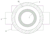
FIG. 1 is a cross-sectional view of a cooling structure of a pipe for injection molding of thermosetting plastic according to the present invention;
FIG. 2 is a partial top view of a cooling structure of a pipe for injection molding of thermosetting plastic according to the present invention;
fig. 3 is an enlarged view of a portion a in fig. 1.
In the figure: the device comprises a pipe body 1, a flow guide layer 2, a high-pressure water tank 3, a sliding chute 4, a pulley 5, a heat conducting plate 6, a telescopic rod 7, an 8L-shaped rod, a hole 9, a cooling layer 10, a collection cavity 11, a fixing plate 12, a piston 13, an annular conveying plate 14 and a sliding groove 15.
Detailed Description
The technical solutions in the embodiments of the present invention will be clearly and completely described below with reference to the drawings in the embodiments of the present invention, and it is obvious that the described embodiments are only a part of the embodiments of the present invention, and not all of the embodiments.
Referring to fig. 1-3, a cooling structure of thermosetting plastic material pipe for injection molding, including body 1 and the inside water conservancy diversion layer 2 of seting up the cavity, water conservancy diversion layer 2 cover is established on the lateral wall of body 1, it is provided with two heat-conducting plates 6 to link up jointly between water conservancy diversion layer 2 and the body 1, heat-conducting plate 6 can conduction temperature, the equal fixedly connected with telescopic link 7 of last lateral wall of every heat-conducting plate 6, all annotate mercury in every telescopic link 7, telescopic link 7 generally comprises flexible female pole and flexible sub-pole, when body 1 is overheated, heat-conducting plate 6 conducts the temperature to telescopic link 7 on, make the mercury in the telescopic link 7 expand by heating, thereby jack-up the sub-pole of telescopic link 7, after the temperature reduces, mercury shrink in the telescopic link 7, make the sub-pole of telescopic.
The outer side wall of the flow guide layer 2 is fixedly connected with two symmetrically arranged high-pressure water tanks 3, each high-pressure water tank 3 is provided with a water outlet, water which can cool the pipe body 1 is filled in the high-pressure water tank 3, the side wall of the flow guide layer 2, which is far away from the high-pressure water tanks 3, is fixedly connected with two symmetrically arranged fixed plates 12, each fixed plate 12 is internally provided with a sliding groove 4, one end of each telescopic rod 7, which is far away from the heat conduction plate 6, is fixedly connected with an L-shaped rod 8, one end of each L-shaped rod 8 is inserted into the sliding groove 4 and is fixedly connected with a pulley 5 matched with the sliding groove 4 in size, the pulley 5 can slide in the sliding groove 4, the outer side wall of the flow guide layer 2 is provided with two water inlets communicated with the water outlets, each water inlet is provided with a sliding groove 15, one end of each L-shaped rod 8, which is far away from, can supply L type pole 8 to slide in sliding tray 15, when the sub-pole of telescopic link 7 rose, drive L type pole 8 and rise, make the water in the high-pressure water tank 3 can flow in water conservancy diversion layer 2, when the sub-pole of telescopic link 7 descends, drive L type pole 8 and reduce, plug up the delivery port, make the water in the high-pressure water tank 3 stop to flow in water conservancy diversion layer 2.
Seted up a plurality of holes 9 on the inner wall of water conservancy diversion layer 2, every hole 9 all is located 6 below of heat-conducting plate, common fixedly connected with slope annular delivery board 14 of placing on the relative lateral wall of water conservancy diversion layer 2, annular delivery board 14 is located hole 9 below, the inside cooling layer 10 of seting up the cooling chamber of fixedly connected with on the lateral wall of body 1, water conservancy diversion layer 2 passes through hole 9 and 10 intercommunications in cooling layer, cooling layer 10 is located body 1 below, water in high pressure water tank 3 can flow in cooling layer 10 through hole 9, cool off body 1.
Be equipped with the overhang on the lower lateral wall of cooling layer 10, the below of cooling layer 10 is equipped with collects chamber 11, piston 13 is installed to the lower lateral wall of overhang, piston 13 has three-way structure, piston 13's two-way inserts respectively in the overhang and the last lateral wall of collecting chamber 11, accessible piston 13 makes rivers flow in collect chamber 11 after the cooling is accomplished, can set up a water pump outside collecting chamber 11, pump back high pressure water tank 3 again after will collecting the water-cooling in the chamber 11 in, it is convenient to retrieve, cycle use, energy saving.
In the invention, when the temperature of the tube body 1 rises, the heat conducting plate 6 conducts the temperature to the telescopic rod 7, so that mercury in the telescopic rod 7 expands to jack up the sub-rod of the telescopic rod 7, the L-shaped rod 8 is driven to rise, water in the high-pressure water tank 3 flows into the flow guide layer 2, flows into the cooling layer 10 through the hole 9 to cool the tube body 1, and after the temperature is reduced, the mercury shrinks to lower the sub-rod of the telescopic rod 7, the L-shaped rod 8 is driven to lower, the water outlet is blocked, water outlet is stopped, and after cooling is finished, the piston 13 is opened to enable the water in the cooling layer 10 to flow into the collecting cavity 11.
The above description is only for the preferred embodiment of the present invention, but the scope of the present invention is not limited thereto, and any person skilled in the art should be considered to be within the technical scope of the present invention, and the technical solutions and the inventive concepts thereof according to the present invention should be equivalent or changed within the scope of the present invention.
Claims (3)
1. The cooling structure of the material pipe for thermosetting plastic injection molding comprises a pipe body (1) and a flow guide layer (2) with a cavity arranged inside, and is characterized in that the flow guide layer (2) is sleeved on the outer side wall of the pipe body (1), a cooling layer (10) with a cooling cavity arranged inside is fixedly connected to the outer side wall of the pipe body (1), the flow guide layer (2) is communicated with the cooling layer (10) through a hole (9), and the cooling layer (10) is located below the pipe body (1); two heat-conducting plates (6) are arranged between the flow guide layer (2) and the pipe body (1) in a penetrating manner, the upper side wall of each heat-conducting plate (6) is fixedly connected with a telescopic rod (7), and mercury is injected into each telescopic rod (7); the outer side wall of the flow guide layer (2) is fixedly connected with two symmetrically arranged high-pressure water tanks (3), each high-pressure water tank (3) is provided with a water outlet, the side wall of one side of the flow guide layer (2) far away from the high-pressure water tanks (3) is fixedly connected with two symmetrically arranged fixed plates (12), and each fixed plate (12) is internally provided with a sliding chute (4); every the equal fixedly connected with L type pole (8) of one end that heat-conducting plate (6) were kept away from in telescopic link (7), every the one end of L type pole (8) all inserts in spout (4) and fixedly connected with and the big or small assorted pulley (5) of spout (4), set up two water inlets with the delivery port intercommunication on the lateral wall of water conservancy diversion layer (2), every sliding tray (15) have all been seted up on the water inlet, every the one end that pulley (5) were kept away from in L type pole (8) all inserts in sliding tray (15).
2. The cooling structure of the material pipe for thermosetting plastic injection molding according to claim 1, wherein a plurality of holes (9) are formed in the inner wall of the flow guide layer (2), each hole (9) is located below the heat conducting plate (6), the side walls of the opposite sides of the flow guide layer (2) are fixedly connected with obliquely placed annular conveying plates (14), and the annular conveying plates (14) are located below the holes (9).
3. The cooling structure of the pipe for injection molding of thermosetting plastic according to claim 1, characterized in that a protruding end is arranged on the lower side wall of the cooling layer (10), a collecting cavity (11) is arranged below the cooling layer (10), a piston (13) is arranged on the lower side wall of the protruding end, the piston (13) has a three-way structure, and two ways of the piston (13) are respectively inserted into the protruding end and the upper side wall of the collecting cavity (11).
Priority Applications (1)
| Application Number | Priority Date | Filing Date | Title |
|---|---|---|---|
| CN201810846381.3A CN108995161B (en) | 2018-07-27 | 2018-07-27 | Cooling structure of material pipe for thermosetting plastic injection molding |
Applications Claiming Priority (1)
| Application Number | Priority Date | Filing Date | Title |
|---|---|---|---|
| CN201810846381.3A CN108995161B (en) | 2018-07-27 | 2018-07-27 | Cooling structure of material pipe for thermosetting plastic injection molding |
Publications (2)
| Publication Number | Publication Date |
|---|---|
| CN108995161A CN108995161A (en) | 2018-12-14 |
| CN108995161B true CN108995161B (en) | 2020-11-06 |
Family
ID=64598150
Family Applications (1)
| Application Number | Title | Priority Date | Filing Date |
|---|---|---|---|
| CN201810846381.3A Active CN108995161B (en) | 2018-07-27 | 2018-07-27 | Cooling structure of material pipe for thermosetting plastic injection molding |
Country Status (1)
| Country | Link |
|---|---|
| CN (1) | CN108995161B (en) |
Families Citing this family (5)
| Publication number | Priority date | Publication date | Assignee | Title |
|---|---|---|---|---|
| CN109757081B (en) * | 2019-01-10 | 2024-01-05 | 中国海洋大学 | Piston heat exchange device of underwater sealed cabin |
| CN110420808A (en) * | 2019-08-19 | 2019-11-08 | 广东宇星众鼎精密科技有限公司 | Novel spot gluing device |
| CN110634673B (en) * | 2019-09-20 | 2021-04-06 | 瑞安市恩驰电子科技有限公司 | Photovoltaic conflux case dc-to-ac converter electric capacity heat sink |
| CN112793104A (en) * | 2020-12-24 | 2021-05-14 | 宜都鑫华光电有限公司 | Temperature control equipment for injection molding of resin optical lens |
| CN114559409B (en) * | 2022-04-27 | 2022-07-05 | 南通茂业电子科技有限公司 | Electromagnetic chuck controller device arranged in high-temperature equipment |
Family Cites Families (3)
| Publication number | Priority date | Publication date | Assignee | Title |
|---|---|---|---|---|
| CN101649826B (en) * | 2009-09-10 | 2011-05-18 | 刘屏 | Air compressor |
| CN203077574U (en) * | 2013-01-29 | 2013-07-24 | 福州富得巴精密机械有限公司 | Water cooling device for cooling injection head of injection machine |
| CN205112302U (en) * | 2015-10-21 | 2016-03-30 | 舟山北化聚合物加工技术研究所有限责任公司 | Can quick refrigerated barrel |
-
2018
- 2018-07-27 CN CN201810846381.3A patent/CN108995161B/en active Active
Also Published As
| Publication number | Publication date |
|---|---|
| CN108995161A (en) | 2018-12-14 |
Similar Documents
| Publication | Publication Date | Title |
|---|---|---|
| CN108995161B (en) | Cooling structure of material pipe for thermosetting plastic injection molding | |
| CN103753735A (en) | Manufacturing system for molding of foaming product | |
| CN210061814U (en) | Injection mold convenient for demolding | |
| CN106956446A (en) | The compression molding device and method of a kind of composite | |
| CN208343435U (en) | A kind of water tank adds water cover silicone gasket production mould | |
| CN210705799U (en) | Injection mold for household appliance accessories | |
| CN214982988U (en) | Milk bottle lid production is with many injection molding mouth injection molding machine | |
| CN213198674U (en) | Quick refrigerated injection mold | |
| CN210702450U (en) | Automatic opening and closing die-casting die | |
| CN210633980U (en) | Secondary eva foaming forming machine for shoemaking | |
| CN209813000U (en) | Automatic high-efficient plastic shell forming die of die sinking | |
| CN211363355U (en) | Cooling device of injection mold | |
| CN210590433U (en) | Injection mold with heat conduction flow distribution plate capable of being cooled rapidly | |
| CN214926829U (en) | Injection mold temperature control device | |
| CN211389941U (en) | Injection mold for injection molding machine | |
| CN112477043A (en) | Dual cooling mechanism for injection mold | |
| CN219686485U (en) | Quick cooling structure for injection mold for vehicle | |
| CN214294273U (en) | Plastic mold for small household appliances | |
| CN213972339U (en) | Plastic injection mold with good heat dissipation effect | |
| CN218803826U (en) | Water cooling mechanism of injection mold | |
| CN217258163U (en) | Injection mold convenient for cooling and demolding | |
| CN211566838U (en) | Quick cooling type injection molding device | |
| CN213972175U (en) | Plastic mold with rapid molding function | |
| CN220923226U (en) | Superhigh temperature rapid cooling and rapid heating equipment | |
| CN213675304U (en) | Fast stripping highlight injection mold for television component |
Legal Events
| Date | Code | Title | Description |
|---|---|---|---|
| PB01 | Publication | ||
| PB01 | Publication | ||
| SE01 | Entry into force of request for substantive examination | ||
| SE01 | Entry into force of request for substantive examination | ||
| GR01 | Patent grant | ||
| GR01 | Patent grant | ||
| TR01 | Transfer of patent right |
Effective date of registration: 20231218 Address after: Room 101, Building 4, No. 25 Tanbu Min'an North Road, Huadu District, Guangzhou City, Guangdong Province, 510800 Patentee after: Guangdong Shenghua Plastic Technology Co.,Ltd. Address before: 241000 Building 1 and 2, No. 20, Weiwu Road, industrial concentration area, Fangcun town (Tiancheng), Jinghu District, Wuhu City, Anhui Province Patentee before: WUHU CHONGXINGLE PLASTIC Co.,Ltd. |
|
| TR01 | Transfer of patent right |