CN108991861B - Rotatable display device for solid wood door model - Google Patents
Rotatable display device for solid wood door model Download PDFInfo
- Publication number
- CN108991861B CN108991861B CN201810844629.2A CN201810844629A CN108991861B CN 108991861 B CN108991861 B CN 108991861B CN 201810844629 A CN201810844629 A CN 201810844629A CN 108991861 B CN108991861 B CN 108991861B
- Authority
- CN
- China
- Prior art keywords
- fixedly connected
- base
- display device
- wood door
- door model
- Prior art date
- Legal status (The legal status is an assumption and is not a legal conclusion. Google has not performed a legal analysis and makes no representation as to the accuracy of the status listed.)
- Expired - Fee Related
Links
Images


Classifications
-
- A—HUMAN NECESSITIES
- A47—FURNITURE; DOMESTIC ARTICLES OR APPLIANCES; COFFEE MILLS; SPICE MILLS; SUCTION CLEANERS IN GENERAL
- A47F—SPECIAL FURNITURE, FITTINGS, OR ACCESSORIES FOR SHOPS, STOREHOUSES, BARS, RESTAURANTS OR THE LIKE; PAYING COUNTERS
- A47F7/00—Show stands, hangers, or shelves, adapted for particular articles or materials
- A47F7/0042—Show stands, hangers, or shelves, adapted for particular articles or materials for flat articles, e.g. panels, tiles
-
- A—HUMAN NECESSITIES
- A47—FURNITURE; DOMESTIC ARTICLES OR APPLIANCES; COFFEE MILLS; SPICE MILLS; SUCTION CLEANERS IN GENERAL
- A47F—SPECIAL FURNITURE, FITTINGS, OR ACCESSORIES FOR SHOPS, STOREHOUSES, BARS, RESTAURANTS OR THE LIKE; PAYING COUNTERS
- A47F5/00—Show stands, hangers, or shelves characterised by their constructional features
- A47F5/02—Rotary display stands
- A47F5/025—Rotary display stands having mechanical drive, e.g. turntables
-
- A—HUMAN NECESSITIES
- A47—FURNITURE; DOMESTIC ARTICLES OR APPLIANCES; COFFEE MILLS; SPICE MILLS; SUCTION CLEANERS IN GENERAL
- A47F—SPECIAL FURNITURE, FITTINGS, OR ACCESSORIES FOR SHOPS, STOREHOUSES, BARS, RESTAURANTS OR THE LIKE; PAYING COUNTERS
- A47F5/00—Show stands, hangers, or shelves characterised by their constructional features
- A47F5/10—Adjustable or foldable or dismountable display stands
Abstract
The invention belongs to the field of display devices, in particular to a display device for a solid wood door model, which aims at solving the problems that the existing display device cannot rotate or has low stability when rotating, poor practical adaptability and incapability of moving for a short distance, and provides the following scheme: the anti-slip device comprises a base, wherein an anti-slip pad is installed at the bottom of the base, a mover is arranged on one side of the base, a sliding groove is formed in the top of the base, a first supporting column is fixed in the center of the top of the base, a first protecting frame is arranged at the top of the first supporting column, a roller bearing is arranged in the center of the bottom of the first protecting frame, a sliding block is arranged inside the sliding groove, and a supporting rod is fixedly connected to the top of the sliding block.
Description
Technical Field
The invention relates to the technical field of display devices, in particular to a rotatable display device for a solid wood door model.
Background
The exhibition means that the product is remarkably displayed in the public, the popularity of the exhibited product is improved, the propaganda and advertising effects on the product are increased, and the exhibition of the solid wood door serving as furniture is very important.
But present display device often does not have rotation function or when rotatory the stability of wood door model is low, dangerous accident takes place easily, be unfavorable for in-service use, secondly, the size ratio of display device show wood door model is more fixed, can not carry out the regulation of height, the actual adaptability that leads to display device is poor, can't satisfy actual demand, in addition, display device is bulky, weight is big, lead to it to be difficult to carry out the removal of short distance, the in-service use effect is poor, therefore, we design a display device for rotatable wood door model.
Disclosure of Invention
The rotatable display device for the solid wood door model, provided by the invention, solves the problems that the display device cannot rotate or is low in stability when rotating, poor in practical adaptability and incapable of moving in a short distance.
In order to achieve the purpose, the invention adopts the following technical scheme:
a rotatable display device for a solid wood door model comprises a base, wherein a non-slip mat is installed at the bottom of the base, a mover is arranged on one side of the base, a sliding groove is formed in the top of the base, a first supporting column is fixed in the center of the top of the base, a first protective frame is arranged at the top of the first supporting column, a roller bearing is arranged in the center of the bottom of the first protective frame, a sliding block is arranged inside the sliding groove, a supporting rod is fixedly connected to the top of the sliding block, a stand column is arranged at the upper end of the base, a first push rod motor is installed at the top of the stand column, a second supporting column is fixedly connected to the top of an output shaft of the first push rod motor, a cross rod is fixedly connected to one side of the top of the second supporting column, a driving motor is installed on the lower side of one end of the cross rod, a connecting, and be provided with the wood door model body between second protective frame and the first protective frame, the first folded plate of one side fixedly connected with of base, a plurality of arc walls have been seted up to the internal surface of spout, movable mounting has the ball on the slider, the through-hole has been seted up at the top of second protective frame, and the inside of second protective frame has seted up the tooth's socket, the inside of tooth's socket is provided with the gear, all be fixed with first spacing lug on the opposite face of first protective frame and second protective frame, the upper and lower both ends of wood door model body all are fixed with the spacing lug of second.
Preferably, the mover comprises a second push rod motor, a lithium battery, a second folded plate, a first baffle, a telescopic shaft, a second baffle, a buffer spring and a universal wheel, the lithium battery is installed at the top of the second push rod motor, the second folded plate is fixed at one side of the second push rod motor, the second folded plate is L-shaped, the first baffle is fixedly connected with an output shaft of the second push rod motor, the first baffle is fixedly connected with the second baffle through the telescopic shaft, the buffer spring is sleeved on the telescopic shaft, the top of the buffer spring is fixedly connected with the bottom of the first baffle, the bottom of the buffer spring is fixedly connected with the top of the second baffle, and the universal wheel is movably installed at the bottom of the second baffle.
Preferably, the number of the balls is a plurality of groups, the outer surfaces of the balls are in contact with the arc-shaped groove, and the first folding plate is in an inverted L shape.
Preferably, the first protection frame is movably mounted on the first support column through a roller bearing, and the top of the support rod is fixedly connected with the bottom end of the first protection frame.
Preferably, the upright posts are fixedly connected with the base through fastening bolts, and the number of the fastening bolts is a plurality of groups.
Preferably, the through hole is communicated with the tooth space, the tooth space is meshed with the gear, and the connecting shaft penetrates through the through hole to be fixedly connected with the gear.
Preferably, the number of the first limit lugs is a plurality of groups, a plurality of the first limit lugs are distributed at equal intervals, and the distance between every two adjacent first limit lugs is equal to the width of the second limit lug.
Preferably, the driving motor is a stepping motor, and a driver is installed on one side of the driving motor.
Compared with the prior art, the invention has the beneficial effects that:
1. according to the invention, through the arrangement of the sliding groove, the first supporting column, the roller bearing, the sliding block, the supporting rod, the driving motor, the arc-shaped groove, the ball, the tooth groove and the gear, the solid wood door model can be conveniently rotated when displayed, so that people can know the solid wood door more conveniently, the rotating process can be realized manually, the rotating automation can also be realized by using the motor, and the actual use effect is good.
2. According to the invention, the first protection frame, the second protection frame, the first limit bump and the second limit bump are arranged, so that the solid wood door model body can be better protected, the stability of the solid wood door model body is improved, the solid wood door model body is prevented from toppling over due to uneven stress during rotation, and dangerous accidents are avoided.
3. According to the solid wood door model display device, the first push rod motor and the second support column are arranged, so that the distance between the first protection frame and the second protection frame can be adjusted, solid wood door models with different sizes can be conveniently displayed, and the actual adaptability of the device is improved.
4. According to the invention, the first folding plate, the second push rod motor, the lithium battery, the second folding plate, the first baffle plate, the telescopic shaft, the second baffle plate, the buffer spring and the universal wheel are arranged, so that the requirement of short-distance movement of the device is met, the moving cost of the device is reduced, the device can be detached when not in use, the attractiveness of the whole device is not influenced, the production cost is low, and the device is suitable for popularization and use.
The invention has simple structure and novel design, can realize the stable rotation of the displayed object in the displaying process, has high safety, improves the actual adaptability of the device, also meets the requirement of the device on short-distance movement, has low production cost and is suitable for popularization and use.
Drawings
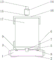
FIG. 1 is a schematic view of the entire structure of a rotatable display device for a solid wood door model according to the present invention;
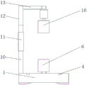
FIG. 2 is a schematic side view of a display device for a rotatable wooden door model according to the present invention;
FIG. 3 is a schematic diagram of a shifter of the display device for a rotatable solid wood door model according to the present invention;
FIG. 4 is a schematic view of a slider structure of the display device for a rotatable wooden door model according to the present invention;
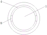
FIG. 5 is a schematic top view of a base of the display device for a rotatable wooden door model according to the present invention;
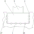
FIG. 6 is a schematic view of a second protective frame of the display device for a rotatable wooden door model according to the present invention;
fig. 7 is a schematic structural view of a joint between a first protective frame and a solid wood door model body of the display device for a rotatable solid wood door model according to the present invention.
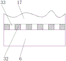
In the figure: the automatic sliding door comprises a base 1, a non-slip mat 2, a moving device 3, a sliding groove 4, a first supporting column 5, a first protective frame 6, a roller bearing 7, a sliding block 8, a supporting rod 9, a vertical column 10, a first push rod motor 11, a second supporting column 12, a cross rod 13, a driving motor 14, a connecting shaft 15, a second protective frame 16, a solid wood door model body 17, a first folded plate 18, a second push rod motor 19, a lithium battery 20, a second folded plate 21, a first baffle 22, a telescopic shaft 23, a second baffle 24, a buffer spring 25, a universal wheel 26, an arc-shaped groove 27, a ball 28, a through hole 29, a tooth groove 30, a gear 31, a first limiting convex block 32 and a second limiting convex block 33.
Detailed Description
The technical solutions in the embodiments of the present invention will be clearly and completely described below with reference to the drawings in the embodiments of the present invention, and it is obvious that the described embodiments are only a part of the embodiments of the present invention, and not all of the embodiments.
Referring to fig. 1-7, a rotatable display device for a solid wood door model comprises a base 1, a non-slip mat 2 is installed at the bottom of the base 1, a mover 3 is arranged at one side of the base 1, a chute 4 is arranged at the top of the base 1, a first support column 5 is fixed at the center of the top of the base 1, a first protective frame 6 is arranged at the top of the first support column 5, a roller bearing 7 is arranged at the center of the bottom of the first protective frame 6, a sliding block 8 is arranged inside the chute 4, a support rod 9 is fixedly connected to the top of the sliding block 8, an upright column 10 is arranged at the upper end of the base 1, a first push rod motor 11 is installed at the top of the upright column 10, a second support column 12 is fixedly connected to the top of an output shaft of the first push rod motor 11, a cross rod 13 is fixedly connected to one side of the top, and the bottom of the output shaft of the driving motor 14 is fixedly connected with a connecting shaft 15, the bottom of the connecting shaft 15 is provided with a second protective frame 16, a solid wood door model body 17 is arranged between the second protective frame 16 and the first protective frame 6, one side of the base 1 is fixedly connected with a first folded plate 18, the inner surface of the sliding groove 4 is provided with a plurality of arc-shaped grooves 27, a sliding block 8 is movably provided with a ball 28, the top of the second protective frame 16 is provided with a through hole 29, the inside of the second protective frame 16 is provided with a tooth groove 30, the inside of the tooth groove 30 is provided with a gear 31, the opposite surfaces of the first protective frame 6 and the second protective frame 16 are respectively fixed with a first limiting lug 32, and the upper end and the lower end of the solid wood door model body 17 are respectively fixed.
The mover 3 comprises a second push rod motor 19, a lithium battery 20, a second folded plate 21, a first baffle plate 22, a telescopic shaft 23, a second baffle plate 24, a buffer spring 25 and a universal wheel 26, wherein the lithium battery 20 is installed at the top of the second push rod motor 19, the second folded plate 21 is fixed at one side of the second push rod motor 19, the second folded plate 21 is L-shaped, the first baffle plate 22 is fixedly connected with an output shaft of the second push rod motor 19, the first baffle plate 22 is fixedly connected with the second baffle plate 24 through the telescopic shaft 23, the buffer spring 25 is sleeved on the telescopic shaft 23, the top of the buffer spring 25 is fixedly connected with the bottom of the first baffle plate 22, the bottom of the buffer spring 25 is fixedly connected with the top of the second baffle plate 24, the universal wheel 26 is movably installed at the bottom of the second baffle plate 24, the number of the balls 28 is a plurality of groups, the outer surfaces of the balls 28 are in contact with an arc-shaped groove 27, the first folded plate 18 is, first protection frame 6 passes through roller bearing 7 movable mounting on first support column 5, the top of bracing piece 9 and the bottom fixed connection of first protection frame 6, stand 10 passes through fastening bolt and base 1 fixed connection, fastening bolt's quantity is a plurality of groups, through-hole 29 is linked together with tooth's socket 30, and tooth's socket 30 meshes with gear 31 mutually, connecting axle 15 passes through-hole 29 and gear 31 fixed connection, the quantity of first spacing lug 32 is a plurality of groups, a plurality of first spacing lugs 32 equidistance distribute, distance between two adjacent first spacing lugs 32 equals the width of second spacing lug 33, driving motor 14 is step motor, and the driver is installed to one side of driving motor 14.
The working principle is as follows: firstly, starting a first push rod motor 11 on an upright post 10, lifting a second protective frame 16 by using a second support post 12 and a cross rod 13, then moving a solid wood door model body 17 to the first protective frame 6, clamping the solid wood door model body 17 on the first protective frame 6 by using a first limit lug 32 and a second limit lug 33, then slowly lowering the second protective frame 16 to make the second protective frame abut against the top of the solid wood door model body 17, then starting a driving motor 14 to convert electric energy into mechanical energy to drive a connecting shaft 15 and a gear 31 to rotate, wherein under the action of a tooth socket 30, the second protective frame 16 drives the solid wood door model body 17 to rotate, so that the display effect is improved, in the rotating process, a sliding block 8 at the bottom end of a support rod 9 slides in a sliding groove 4 under the action of a ball 28, an anti-skid pad 2 at the bottom end of a base 1 has the function of anti-skid, and when the device needs to be moved, firstly, the mover 3 is clamped on one side of the base 1 by the first folding plate 18 and the second folding plate 21, then the second push rod motor 19 is started by the electric energy provided by the lithium battery 20, the universal wheel 26 is pushed to descend to be in contact with the ground, and therefore the position of the base 1 is raised, and then the movement is completed.
The above description is only for the preferred embodiment of the present invention, but the scope of the present invention is not limited thereto, and any person skilled in the art should be considered to be within the technical scope of the present invention, and the technical solutions and the inventive concepts thereof according to the present invention should be equivalent or changed within the scope of the present invention.
Claims (6)
1. A rotatable display device for a solid wood door model comprises a base (1) and is characterized in that an anti-slip mat (2) is installed at the bottom of the base (1), a mover (3) is arranged on one side of the base (1), a sliding groove (4) is formed in the top of the base (1), a first supporting column (5) is fixed in the center of the top of the base (1), a first protective frame (6) is arranged at the top of the first supporting column (5), the first protective frame (6) is movably installed on the first supporting column (5) through a roller bearing (7), a sliding block (8) is arranged inside the sliding groove (4), a supporting rod (9) is fixedly connected to the top of the sliding block (8), the top of the supporting rod (9) is fixedly connected with the bottom end of the first protective frame (6), a stand column (10) is arranged at the upper end of the base (1), a first push rod motor (11) is installed at the top of the upright post (10), a second supporting column (12) is fixedly connected to the top of an output shaft of the first push rod motor (11), a cross rod (13) is fixedly connected to one side of the top of the second supporting column (12), a driving motor (14) is installed at the lower side of one end of the cross rod (13), a connecting shaft (15) is fixedly connected to the bottom of the output shaft of the driving motor (14), a second protective frame (16) is arranged at the bottom of the connecting shaft (15), a solid wood door model body (17) is arranged between the second protective frame (16) and the first protective frame (6), a plurality of arc-shaped grooves (27) are formed in the inner surface of the sliding groove (4), balls (28) are movably installed on the sliding block (8), and a through hole (29) is formed in the top of the second protective frame (16, just tooth's socket (30) have been seted up to the inside of second protection frame (16), the inside of tooth's socket (30) is provided with gear (31), through-hole (29) with tooth's socket (30) are linked together, just tooth's socket (30) with gear (31) mesh mutually, connecting axle (15) are passed through-hole (29) with gear (31) fixed connection, first protection frame (6) with all be fixed with first spacing lug (32) on the opposite face of second protection frame (16), the upper and lower both ends of wood door model body (17) all are fixed with second spacing lug (33), through first spacing lug (32) with second spacing lug (33) will wood door model body (17) card first protection frame (6).
2. The rotatable display device for the solid wood door model as claimed in claim 1, wherein the mover (3) comprises a second push rod motor (19), a lithium battery (20), a second folded plate (21), a first baffle plate (22), a telescopic shaft (23), a second baffle plate (24), a buffer spring (25) and a universal wheel (26), the lithium battery (20) is installed at the top of the second push rod motor (19), the second folded plate (21) is fixed at one side of the second push rod motor (19), the second folded plate (21) is L-shaped, the first baffle plate (22) is fixedly connected with the output shaft of the second push rod motor (19), the first baffle plate (22) is fixedly connected with the second baffle plate (24) through the telescopic shaft (23), the buffer spring (25) is sleeved on the telescopic shaft (23), and the top of the buffer spring (25) is fixedly connected with the bottom of the first baffle plate (22), the bottom of the buffer spring (25) is fixedly connected with the top of the second baffle plate (24), and the universal wheel (26) is movably mounted at the bottom of the second baffle plate (24).
3. The rotatable wooden door model display device as claimed in claim 1, wherein the number of the balls (28) is several groups, and the outer surface of the balls (28) is in contact with the arc-shaped grooves (27).
4. The rotatable display device for the solid wood door model as claimed in claim 1, wherein the columns (10) are fixedly connected with the base (1) through fastening bolts, and the number of the fastening bolts is a plurality of groups.
5. The rotatable wood door model display device as claimed in claim 1, wherein the number of the first limiting protrusions (32) is several groups, several first limiting protrusions (32) are distributed at equal intervals, and the distance between two adjacent first limiting protrusions (32) is equal to the width of the second limiting protrusion (33).
6. The rotatable display device for wooden door models as claimed in claim 1, wherein the driving motor (14) is a stepping motor, and a driver is installed at one side of the driving motor (14).
Priority Applications (1)
| Application Number | Priority Date | Filing Date | Title |
|---|---|---|---|
| CN201810844629.2A CN108991861B (en) | 2018-07-27 | 2018-07-27 | Rotatable display device for solid wood door model |
Applications Claiming Priority (1)
| Application Number | Priority Date | Filing Date | Title |
|---|---|---|---|
| CN201810844629.2A CN108991861B (en) | 2018-07-27 | 2018-07-27 | Rotatable display device for solid wood door model |
Publications (2)
| Publication Number | Publication Date |
|---|---|
| CN108991861A CN108991861A (en) | 2018-12-14 |
| CN108991861B true CN108991861B (en) | 2021-02-26 |
Family
ID=64598412
Family Applications (1)
| Application Number | Title | Priority Date | Filing Date |
|---|---|---|---|
| CN201810844629.2A Expired - Fee Related CN108991861B (en) | 2018-07-27 | 2018-07-27 | Rotatable display device for solid wood door model |
Country Status (1)
| Country | Link |
|---|---|
| CN (1) | CN108991861B (en) |
Families Citing this family (2)
| Publication number | Priority date | Publication date | Assignee | Title |
|---|---|---|---|---|
| CN110731662B (en) * | 2019-11-19 | 2021-01-05 | 赣州豪鼎家具有限公司 | Rotary exhibition stand for door and window exhibition |
| CN111297125A (en) * | 2020-03-18 | 2020-06-19 | 孙昊喆 | Rotationally adjustable display rack for aerospace model |
Citations (5)
| Publication number | Priority date | Publication date | Assignee | Title |
|---|---|---|---|---|
| US4023684A (en) * | 1975-09-08 | 1977-05-17 | Rack Engineering Company | Cantilever rack structure |
| JP2002300944A (en) * | 2001-04-04 | 2002-10-15 | Okamura Corp | Merchandise display shelf |
| CN106073312A (en) * | 2016-08-12 | 2016-11-09 | 无锡博辉金属制品有限公司 | A kind of novel solar water heater vacuum tube sells frame |
| CN206931249U (en) * | 2017-05-03 | 2018-01-26 | 中职北方智扬(北京)教育科技有限公司 | A kind of vehicle teaching showing stand |
| CN107928268A (en) * | 2017-10-17 | 2018-04-20 | 江阴市永昌交通机械部件有限公司 | A kind of flexible axle sale displaying device with tension function |
Family Cites Families (10)
| Publication number | Priority date | Publication date | Assignee | Title |
|---|---|---|---|---|
| CN2471229Y (en) * | 2001-03-08 | 2002-01-16 | 陈仲飞 | Turntable for commodity on display |
| US20090184067A1 (en) * | 2008-01-22 | 2009-07-23 | Mcadory Jim Davis | Adjustable boot racking assembly |
| CN205107082U (en) * | 2015-11-19 | 2016-03-30 | 东北石油大学 | Sample display device for business administration |
| CN205548156U (en) * | 2016-03-26 | 2016-09-07 | 李帅 | Adjustable car show stand |
| CN205866401U (en) * | 2016-05-13 | 2017-01-11 | 武汉华康世纪洁净室技术工程有限公司 | Multi -functional storage cabinet |
| CN206213692U (en) * | 2016-08-30 | 2017-06-06 | 宁夏优讯信息技术有限公司 | A kind of good use for electronic products sale frame of crushing resistance |
| CN106859155A (en) * | 2017-04-14 | 2017-06-20 | 湖州练市宇颖鞋业有限公司 | Rotary exhibiting device is used in a kind of leather shoes sale |
| CN107296435A (en) * | 2017-06-23 | 2017-10-27 | 王玉忠 | A kind of public art rotary show stand of statue |
| CN107348756A (en) * | 2017-08-07 | 2017-11-17 | 湖州胎福工艺品有限公司 | A kind of multifunctional ceramic handicraft showing stand |
| CN108294558B (en) * | 2018-01-25 | 2019-11-12 | 苏州南师大科技园投资管理有限公司 | A kind of multiple sample presentation devices of bioconversion medium rotary type |
-
2018
- 2018-07-27 CN CN201810844629.2A patent/CN108991861B/en not_active Expired - Fee Related
Patent Citations (5)
| Publication number | Priority date | Publication date | Assignee | Title |
|---|---|---|---|---|
| US4023684A (en) * | 1975-09-08 | 1977-05-17 | Rack Engineering Company | Cantilever rack structure |
| JP2002300944A (en) * | 2001-04-04 | 2002-10-15 | Okamura Corp | Merchandise display shelf |
| CN106073312A (en) * | 2016-08-12 | 2016-11-09 | 无锡博辉金属制品有限公司 | A kind of novel solar water heater vacuum tube sells frame |
| CN206931249U (en) * | 2017-05-03 | 2018-01-26 | 中职北方智扬(北京)教育科技有限公司 | A kind of vehicle teaching showing stand |
| CN107928268A (en) * | 2017-10-17 | 2018-04-20 | 江阴市永昌交通机械部件有限公司 | A kind of flexible axle sale displaying device with tension function |
Also Published As
| Publication number | Publication date |
|---|---|
| CN108991861A (en) | 2018-12-14 |
Similar Documents
| Publication | Publication Date | Title |
|---|---|---|
| CN108991861B (en) | Rotatable display device for solid wood door model | |
| CN113022369B (en) | New energy vehicle battery disassembling device | |
| CN111622478A (en) | A adjustable construction platform for house construction | |
| CN205777739U (en) | Two layer bicycle lugs | |
| CN208167588U (en) | Warning sign is used in a kind of construction of meeting lane | |
| CN213230100U (en) | Automatic storage goods shelves height control adjusting device | |
| CN108482532B (en) | Solar multi-surface rotary type three-dimensional bicycle parking device | |
| CN203601448U (en) | Three-dimensional bicycle stand | |
| CN2451559Y (en) | Wheel type shears frame lifting jack | |
| CN213950460U (en) | Jacking device for rail transit maintenance equipment | |
| CN105346912B (en) | A kind of device for facilitating shop assistant to take document | |
| CN210646776U (en) | Lithium cell electricity core pole piece breaker | |
| CN110264915B (en) | Market promotes user's show shelf of preventing wind outward | |
| CN209090569U (en) | A kind of movable type craftwork showing stand | |
| CN210043629U (en) | Show shelf convenient to height-adjusting | |
| CN215913866U (en) | But drawing show shelf for architectural design of angle modulation | |
| CN215604594U (en) | Multifunctional exhibition stand | |
| CN217151516U (en) | Adjustable isolation fence for house building engineering | |
| CN220035250U (en) | Municipal construction warning frame that can accomodate | |
| CN211344634U (en) | Outdoor propaganda equipment of portable ideological and political education | |
| CN220796054U (en) | Indicator light with good protection | |
| CN220226467U (en) | Isolation warning device | |
| CN210622146U (en) | Novel guardrail mounting cover plate | |
| CN220272109U (en) | Novel show device | |
| CN220847285U (en) | Guard bar |
Legal Events
| Date | Code | Title | Description |
|---|---|---|---|
| PB01 | Publication | ||
| PB01 | Publication | ||
| SE01 | Entry into force of request for substantive examination | ||
| SE01 | Entry into force of request for substantive examination | ||
| GR01 | Patent grant | ||
| GR01 | Patent grant | ||
| CF01 | Termination of patent right due to non-payment of annual fee | ||
| CF01 | Termination of patent right due to non-payment of annual fee |
Granted publication date: 20210226 Termination date: 20210727 |