CN108886443B - Sounding reference signal transmission for carrier aggregation - Google Patents
Sounding reference signal transmission for carrier aggregation Download PDFInfo
- Publication number
- CN108886443B CN108886443B CN201780018113.6A CN201780018113A CN108886443B CN 108886443 B CN108886443 B CN 108886443B CN 201780018113 A CN201780018113 A CN 201780018113A CN 108886443 B CN108886443 B CN 108886443B
- Authority
- CN
- China
- Prior art keywords
- configuration
- srs
- carriers
- data transmission
- transmission
- Prior art date
- Legal status (The legal status is an assumption and is not a legal conclusion. Google has not performed a legal analysis and makes no representation as to the accuracy of the status listed.)
- Active
Links
Images


Classifications
-
- H—ELECTRICITY
- H04—ELECTRIC COMMUNICATION TECHNIQUE
- H04L—TRANSMISSION OF DIGITAL INFORMATION, e.g. TELEGRAPHIC COMMUNICATION
- H04L5/00—Arrangements affording multiple use of the transmission path
- H04L5/003—Arrangements for allocating sub-channels of the transmission path
- H04L5/0048—Allocation of pilot signals, i.e. of signals known to the receiver
-
- H—ELECTRICITY
- H04—ELECTRIC COMMUNICATION TECHNIQUE
- H04L—TRANSMISSION OF DIGITAL INFORMATION, e.g. TELEGRAPHIC COMMUNICATION
- H04L5/00—Arrangements affording multiple use of the transmission path
- H04L5/0001—Arrangements for dividing the transmission path
- H04L5/0003—Two-dimensional division
- H04L5/0005—Time-frequency
- H04L5/0007—Time-frequency the frequencies being orthogonal, e.g. OFDM(A), DMT
- H04L5/001—Time-frequency the frequencies being orthogonal, e.g. OFDM(A), DMT the frequencies being arranged in component carriers
-
- H—ELECTRICITY
- H04—ELECTRIC COMMUNICATION TECHNIQUE
- H04L—TRANSMISSION OF DIGITAL INFORMATION, e.g. TELEGRAPHIC COMMUNICATION
- H04L5/00—Arrangements affording multiple use of the transmission path
- H04L5/0091—Signaling for the administration of the divided path
- H04L5/0094—Indication of how sub-channels of the path are allocated
-
- H—ELECTRICITY
- H04—ELECTRIC COMMUNICATION TECHNIQUE
- H04L—TRANSMISSION OF DIGITAL INFORMATION, e.g. TELEGRAPHIC COMMUNICATION
- H04L5/00—Arrangements affording multiple use of the transmission path
- H04L5/14—Two-way operation using the same type of signal, i.e. duplex
-
- H—ELECTRICITY
- H04—ELECTRIC COMMUNICATION TECHNIQUE
- H04L—TRANSMISSION OF DIGITAL INFORMATION, e.g. TELEGRAPHIC COMMUNICATION
- H04L5/00—Arrangements affording multiple use of the transmission path
- H04L5/14—Two-way operation using the same type of signal, i.e. duplex
- H04L5/1469—Two-way operation using the same type of signal, i.e. duplex using time-sharing
-
- H—ELECTRICITY
- H04—ELECTRIC COMMUNICATION TECHNIQUE
- H04W—WIRELESS COMMUNICATION NETWORKS
- H04W72/00—Local resource management
- H04W72/04—Wireless resource allocation
- H04W72/044—Wireless resource allocation based on the type of the allocated resource
- H04W72/0446—Resources in time domain, e.g. slots or frames
-
- H—ELECTRICITY
- H04—ELECTRIC COMMUNICATION TECHNIQUE
- H04W—WIRELESS COMMUNICATION NETWORKS
- H04W72/00—Local resource management
- H04W72/20—Control channels or signalling for resource management
- H04W72/23—Control channels or signalling for resource management in the downlink direction of a wireless link, i.e. towards a terminal
-
- H—ELECTRICITY
- H04—ELECTRIC COMMUNICATION TECHNIQUE
- H04W—WIRELESS COMMUNICATION NETWORKS
- H04W74/00—Wireless channel access, e.g. scheduled or random access
- H04W74/08—Non-scheduled or contention based access, e.g. random access, ALOHA, CSMA [Carrier Sense Multiple Access]
- H04W74/0833—Non-scheduled or contention based access, e.g. random access, ALOHA, CSMA [Carrier Sense Multiple Access] using a random access procedure
Abstract
Methods, systems, and devices for wireless communication are described. A User Equipment (UE) may indicate to a base station a number of Uplink (UL) Component Carriers (CCs) that the UE is capable of supporting. The base station may configure the UE for Carrier Aggregation (CA) and for one or more secondary UL CCs. The CA configuration may include a CC for UL data transmission, and the secondary UL configuration may include a CC for UL reference signal or random access channel transmission. The secondary UL CCs may thus be used for Sounding Reference Signal (SRS) transmission even if the UE is not otherwise configured for UL data transmission on these CCs. UL data transmissions on the CA carriers may be sent at the same time as SRS transmissions or during different Transmission Time Intervals (TTIs), depending on the UE capabilities.
Description
Cross-referencing
The present patent application claims priority from U.S. patent application No.15/467,459 entitled "Sounding Reference Signal Transmission For Enhanced Carrier Aggregation" filed by Chen et al at 23.3.2017 and U.S. provisional patent application No.62/313,100 entitled "Sounding Reference Signal Transmission For Enhanced Carrier Aggregation" filed by Chen et al at 24.2016, each of which is assigned to the assignee of the present application.
Background
The following relates generally to wireless communications, and more particularly to Sounding Reference Signals (SRS) under asymmetric enhanced carrier aggregation (eCA).
Wireless communication systems are widely deployed to provide various types of communication content such as voice, video, packet data, messaging, broadcast, and so on. These systems may be able to support communication with multiple users by sharing the available system resources (e.g., time, frequency, and power). Examples of such multiple-access systems include Code Division Multiple Access (CDMA) systems, Time Division Multiple Access (TDMA) systems, Frequency Division Multiple Access (FDMA) systems, and Orthogonal Frequency Division Multiple Access (OFDMA) systems. A wireless multiple-access communication system may include several base stations, each of which simultaneously supports communication for multiple communication devices, which may each be referred to as User Equipment (UE).
A wireless communication system may support multiple Component Carriers (CCs) in a Carrier Aggregation (CA) or eCA configuration. The CC may be configured for Uplink (UL) and Downlink (DL) communication between the base station and the UE. The UE may transmit a reference signal (e.g., SRS) to indicate the quality of the frequency channel used for communicating with the base station.
The wireless communication system may configure only a portion of the UL CCs that the UE can support, and may reserve SRS transmission for uplink CCs available to the CA. This may result in inaccurate estimation of channel conditions for frequency bands where UL CCs are not configured, which may result in inefficient use of the channel and reduced throughput.
SUMMARY
A User Equipment (UE) may indicate to a base station a number of Uplink (UL) Component Carriers (CCs) that the UE is capable of supporting. The base station may then configure the UE to operate with multiple CCs in a Carrier Aggregation (CA) configuration and a secondary UL configuration. The CA configuration may include CCs for UL data transmission, and the secondary UL configuration may include CCs for UL reference signal transmission (e.g., Sounding Reference Signal (SRS)) or Random Access Channel (RACH) transmission. The UE may thus transmit SRS or RACH messages on UL CCs that were not otherwise configured for the UE. The UL data transmission may be sent at the same time as the SRS transmission (if the UE is capable of parallel UL transmission) or during a different Transmission Time Interval (TTI) if the UE is not capable of parallel UL transmission.
A method of wireless communication is described. The method may include transmitting an indication of a number of UL carriers that the UE is capable of supporting; receiving signaling indicating a CA configuration and a secondary UL configuration, the CA configuration comprising one or more carriers configured for UL data transmission and the secondary UL configuration comprising one or more carriers configured for UL reference signal transmission; and transmitting the SRS using one or more carriers in the secondary UL configuration based on the CA configuration and the UE capability.
An apparatus for wireless communication is described. The apparatus may include means for transmitting an indication of UE capabilities; means for receiving a CA configuration and a secondary UL configuration, the CA configuration comprising one or more carriers configured for UL data transmission and the secondary UL configuration comprising one or more carriers configured for UL reference signal transmission; and means for transmitting the SRS using one or more carriers in the secondary UL configuration based on the CA configuration and the UE capability.
Another apparatus is described. The apparatus may include a processor, a memory in electronic communication with the processor, and instructions stored in the memory. The instructions are operable to cause a processor to transmit an indication of UE capabilities; receiving a CA configuration and a secondary UL configuration, the CA configuration comprising one or more carriers configured for UL data transmission and the secondary UL configuration comprising one or more carriers configured for UL reference signal transmission; and transmitting the SRS using one or more carriers in the secondary UL configuration based on the CA configuration and the UE capability.
A non-transitory computer-readable medium for wireless communication is described. The non-transitory computer-readable medium may include instructions for causing a processor to: transmitting an indication of UE capability; receiving a CA configuration and a secondary UL configuration, the CA configuration comprising one or more carriers configured for UL data transmission and the secondary UL configuration comprising one or more carriers configured for UL reference signal transmission; and transmitting the SRS using one or more carriers in the secondary UL configuration based on the CA configuration and the UE capability.
In some examples of the methods, apparatus (devices), or non-transitory computer-readable media described herein, the CA configuration includes a first number (e.g., quantity) of carriers configured for Downlink (DL) transmissions and a second number of carriers configured for UL transmissions, and wherein the first number is greater than the second number. In some examples of the methods, apparatus (devices), or non-transitory computer-readable media described herein, the secondary UL configuration includes a third number of carriers, and wherein the third number is based on a difference between the first number and the second number.
Some examples of the methods, apparatus (devices), or non-transitory computer-readable media described herein may further include processes, features, devices, or instructions for transmitting UL data transmissions on one or more carriers configured for UL data transmissions, wherein the UL data is transmitted during the same TTI as the SRS.
In some examples of the methods, apparatus (devices), or non-transitory computer-readable media described herein, the one or more carriers configured for UL data transmission comprise at least one carrier configured for Time Division Duplex (TDD). Some examples of methods, apparatus (devices), or non-transitory computer-readable media described herein may further include processes, features, devices, or instructions for transmitting an additional SRS, wherein the SRS is transmitted using the first set of antennas and the additional SRS is transmitted using the second set of antennas.
In some examples of the methods, apparatus (devices), or non-transitory computer-readable media described herein, a first set of antennas is selected for transmission on one or more carriers used for SRS and a second set of antennas is selected for transmission on additional carriers used for additional SRS. In some examples, the SRS is a periodic SRS or an aperiodic SRS and the additional SRS is a periodic SRS or an aperiodic SRS, and the first set of antennas is selected based on the SRS being the periodic SRS and the second set of antennas is selected based on the additional SRS being the aperiodic SRS. Additionally or alternatively, some examples may include receiving Radio Resource Control (RRC) signaling or Downlink Control Information (DCI), and the first set of antennas or the second set of antennas may be selected based at least in part on the RRC signaling or DCI.
Some examples of the methods, apparatus (devices), or non-transitory computer-readable media described herein may further include processes, features, devices, or instructions for identifying one or more switching symbols based on the transmitted SRS or SRS location, or both, and rate matching or puncturing UL data transmissions based on the one or more switching symbols. Some examples also include processes, features, means, or instructions for initiating a UL data transmission during a symbol period after the one or more switching symbols.
In some examples of the methods, apparatus (devices), or non-transitory computer-readable media described herein, the one or more switching symbols are identified based on a position of a symbol in a subframe that includes the SRS relative to other symbols in the subframe. Some examples include processes, features, means, or instructions for transmitting an indication of a switching time (e.g., which may be included in an indication of UE capabilities), wherein the one or more switching symbols are based on the switching time.
In some examples of the methods, apparatuses (devices), or non-transitory computer-readable media described herein, the one or more switching symbols are identified based on a symbol position of the SRS. In some examples, the one switching symbol is identified based on a combination of carriers used for SRS and UL data transmission.
Some examples of the methods, apparatus (devices), or non-transitory computer-readable media described herein may further include processes, features, devices, or instructions for transmitting a Physical Random Access Channel (PRACH) message on one or more carriers in the secondary UL configuration. Some examples further include processes, features, means, or instructions for receiving a second secondary configuration for a second Timing Adjustment Group (TAG), wherein the secondary UL configuration is associated with the first TAG.
In some examples of the methods, apparatus (devices), or non-transitory computer-readable media described herein, the CA configuration comprises a secondary UL configuration. In some examples of the methods, apparatus (devices), or non-transitory computer-readable media described herein, the secondary UL configuration is different from the CA configuration.
In some examples of the methods, apparatus (devices), or non-transitory computer-readable media described herein, the CA configuration is part of a dual connectivity configuration. In some examples, the CA configuration includes a set of Physical Uplink Control Channel (PUCCH) groups, and wherein the secondary UL corresponds to one PUCCH group of the set of PUCCH groups.
In some examples of the methods, apparatus (devices), or non-transitory computer-readable media described herein, the one or more carriers configured for UL data transmission comprise a carrier of a first TAG and the one or more carriers configured for UL reference signals comprise a carrier of a second TAG.
Another method of wireless communication is described. The method may include receiving an indication of UE capabilities; transmitting a CA configuration and a secondary UL configuration for the UE, the CA configuration comprising one or more carriers configured for UL data transmission and the secondary UL configuration comprising one or more carriers configured for UL reference signal transmission; and receiving the SRS using one or more carriers in the secondary UL configuration based on the CA configuration and the UE capability.
Another apparatus for wireless communication is also described. The apparatus may include means for receiving an indication of UE capabilities; means for transmitting a CA configuration and a secondary UL configuration for the UE, the CA configuration comprising one or more carriers configured for UL data transmission and the secondary UL configuration comprising one or more carriers configured for UL reference signal transmission; and means for receiving the SRS using one or more carriers in the secondary UL configuration based on the CA configuration and the UE capability.
Another apparatus is described. The apparatus may include a processor, a memory in electronic communication with the processor, and instructions stored in the memory. The instructions are operable to cause the processor to receive an indication of UE capabilities; transmitting a CA configuration and a secondary UL configuration for the UE, the CA configuration comprising one or more carriers configured for UL data transmission and the secondary UL configuration comprising one or more carriers configured for UL reference signal transmission; and receiving the SRS using one or more carriers in the secondary UL configuration based on the CA configuration and the UE capability.
Another non-transitory computer-readable medium for wireless communication is described. The non-transitory computer-readable medium may include instructions for causing a processor to: receiving an indication of UE capabilities; transmitting a CA configuration and a secondary UL configuration for the UE, the CA configuration comprising one or more carriers configured for UL data transmission and the secondary UL configuration comprising one or more carriers configured for UL reference signal transmission; and receiving the SRS using one or more carriers in the secondary UL configuration based on the CA configuration and the UE capability.
In some examples of the methods, apparatus (devices), or non-transitory computer-readable media described herein, the CA configuration includes a first number of carriers configured for DL transmissions and a second number of carriers configured for UL transmissions, and wherein the first number is greater than the second number.
Some examples of the methods, apparatus (devices), or non-transitory computer-readable media described herein may further include processes, features, devices, or instructions for receiving UL data transmissions on one or more carriers configured for UL data transmissions, wherein the UL data is transmitted during the same TTI as the SRS.
Some examples of the methods, apparatus (devices), or non-transitory computer-readable media described herein may further include processes, features, devices, or instructions for identifying one or more switching symbols based on the SRS. Some examples of the methods, apparatus (devices), or non-transitory computer-readable media described herein may further include processes, features, devices, or instructions for receiving a UL data transmission during a symbol period after the one or more switching symbols.
Some examples of the methods, apparatus (devices), or non-transitory computer-readable media described herein may further include processes, features, devices, or instructions for receiving an indication of a switching time, wherein the one or more switching symbols are based on the switching time. Some examples of the methods, apparatus (devices), or non-transitory computer-readable media described herein may further include processes, features, devices, or instructions for receiving PRACH messages on one or more carriers in a secondary UL configuration.
Some examples of the methods, apparatuses (devices), or non-transitory computer-readable media described herein may further include processes, features, means, or instructions for communicating a second auxiliary configuration for a second TAG, wherein the auxiliary UL configuration is associated with the first TAG.
Brief Description of Drawings
Fig. 1 illustrates an example of a wireless communication system supporting Sounding Reference Signals (SRS) under asymmetric enhanced carrier aggregation (eCA) in accordance with aspects of the present disclosure;
fig. 2 illustrates an example of a wireless communication system supporting SRS under asymmetric eCA, in accordance with aspects of the present disclosure;
fig. 3 illustrates an example of a secondary Component Carrier (CC) configuration supporting SRS under asymmetric eCA, in accordance with aspects of the present disclosure;
fig. 4 illustrates an example of a process flow in a system supporting SRS under asymmetric eCA, in accordance with aspects of the present disclosure;
fig. 5 through 7 show block diagrams of wireless devices supporting SRS under asymmetric eCA, in accordance with aspects of the present disclosure;
fig. 8 illustrates a block diagram of a system including UEs supporting SRS under asymmetric eCA, in accordance with aspects of the present disclosure;
fig. 9 to 11 show block diagrams of wireless devices supporting SRS under asymmetric eCA, in accordance with aspects of the present disclosure;
fig. 12 illustrates a block diagram of a system including a base station supporting SRS under asymmetric eCA, in accordance with aspects of the present disclosure; and
fig. 13 through 19 illustrate methods for SRS under asymmetric ecas, in accordance with aspects of the present disclosure.
Detailed Description
A User Equipment (UE) may be configured with a secondary Uplink (UL) Component Carrier (CC) for reference signal transmission and a UL CC for data transmission in a Carrier Aggregation (CA) configuration. The secondary UL CC may be used, for example, for Sounding Reference Signal (SRS) and Physical Random Access Channel (PRACH) transmissions, but not necessarily for uplink data transmissions (e.g., such as transmissions on a Physical Uplink Shared Channel (PUSCH)). A UE may be configured with a secondary CC based on the UE's ability to support communication on multiple CCs. For example, a UE may support parallel UL transmissions on multiple different CCs, such that the UE may be configured with CCs for UL data transmission and UL reference signal transmission.
The secondary CC may be used in parallel (e.g., concurrently) with the UL CC in CA; or alternatively, the secondary CC may be used during a Transmission Time Interval (TTI) when data is not transmitted on the UL CC in the CA configuration. UEs that do not support parallel transmission may employ SRS antenna switching. For non-parallel secondary CC configurations (e.g., configuration of antenna switching parameters), a gap duration may be indicated to define a time duration for switching to and from the UL CC.
In some cases, the transmit antennas of the UE may be split between different CCs for periodic or aperiodic SRS transmission. In a dual connectivity scenario, SRS switching may be applicable to each of two groups configured for dual connectivity. UEs that are not capable of parallel transmission may be configured with UL CCs based on UL CC symbol availability. The signaling of the time duration or gap for a UE to switch from one CC to another may depend on the frequency band being utilized.
The aspects of the present disclosure introduced above are described more fully below in the context of a wireless communication system. Examples of wireless communication systems are described that support the use of secondary UL CCs to leverage the ability of a UE to transmit on multiple CCs, including CCs other than those configured for UL data. Aspects of the present disclosure are further illustrated and described with reference to apparatus diagrams, system diagrams, and flow diagrams related to SRS under asymmetric eCA.
Fig. 1 illustrates an example of a wireless communication system 100 in accordance with aspects of the present disclosure. The wireless communication system 100 includes base stations 105, UEs 115, and a core network 130. In some examples, the wireless communication system 100 may be a Long Term Evolution (LTE)/LTE-advanced (LTE-a) network.
The base station 105 may communicate wirelessly with the UE 115 via one or more base station antennas. Each base station 105 may provide communication coverage for a respective geographic coverage area 110. The communication link 125 shown in the wireless communication system 100 may include UL transmissions from the UE 115 to the base station 105, or Downlink (DL) transmissions from the base station 105 to the UE 115. UEs 115 may be dispersed throughout the wireless communication system 100, and each UE 115 may be stationary or mobile. UE 115 may also be referred to as a mobile station, subscriber station, remote unit, wireless device, Access Terminal (AT), handset, user agent, client, or similar terminology. The UE 115 may also be a cellular phone, a wireless modem, a handheld device, a personal computer, a tablet device, a personal electronic device, a Machine Type Communication (MTC) device, and so on.
The base stations 105 may communicate with the core network 130 and with each other. For example, the base station 105 may interface with the core network 130 over a backhaul link 132 (e.g., S1, etc.). The base stations 105 may communicate with each other over a backhaul link 134 (e.g., X2, etc.) either directly or indirectly (e.g., through the core network 130). The base station 105 may perform radio configuration and scheduling for communicating with the UE 115, or may operate under the control of a base station controller (not shown). In some examples, the base station 105 may be a macro cell, a small cell, a hot spot, and/or the like. The base station 105 may also be referred to as an evolved node B (eNB) 105.
The UE 115 may be configured with several CCs (e.g., up to 32 CCs) for CA. The CCs of the CA may be associated with one or several base stations 105. Each CC is backward compatible and spans a different frequency gap (e.g., up to 20 MHz). Multiple CCs configured for UE 115 may span a maximum frequency region (e.g., up to 640 MHz). The CCs in CA may be full Frequency Division Duplex (FDD), full Time Division Duplex (TDD), or a mixture of FDD and TDD. Different TDD CCs may have the same or different UL/DL configurations. In some cases, the special subframes may be configured differently for different TDD CCs. One CC may be configured as a primary CC (e.g., PCell or PCC) of the UE, while other CCs may be configured as secondary CCs (e.g., scells or SCCs). The PCell may carry a Physical Uplink Control Channel (PUCCH). Some CCs may be on a licensed spectrum and some other CCs may be on an unlicensed spectrum or a shared spectrum.
In some examples, a UE 115 may be configured with a large number of CCs (e.g., 20 or more CCs). This type of configuration may be referred to as enhanced ca (eca). The term eCA may also refer to an earlier deployment enhanced CA configuration relative to a CA aggregation scheme. For example, using a secondary UL CC or dynamically switching between CCs for certain transmissions may be examples of ecas. The terms CA and eCA may thus be used interchangeably to describe features related to a multi-carrier configuration. In some cases, ecas may refer to CAs in enhanced systems.
In some cases, a UE 115 may be served by cells from two or more base stations 105 connected by a non-ideal backhaul link 134 in dual connectivity operation. For example, the connection between the serving base stations 105 may not be sufficient to facilitate accurate timing coordination. Thus, in some cases, the cell serving the UE 115 may be divided into multiple TAGs. In another example, one or more CCs may be connected with one or more repeaters, while other CCs may operate without repeaters. As a result, in some cases, the cell or different CCs serving the UE 115 may be divided into multiple TAGs. Each TAG may be associated with a different timing offset so that the UE 115 may synchronize UL transmissions differently for different UL carriers.
In dual connectivity, cells may be divided into two groups, a Primary Cell Group (PCG) and a Secondary Cell Group (SCG). Each group may have one or more cells in CA and may use a single cell to carry PUCCH. Thus, in some cases, a UE may be configured with a PCell and another CC may be configured as a primary secondary CC (e.g., PSCell). The PSCell may also carry PUCCH (e.g., for SCG), but may not include all attributes of the PCell. UL control information may be separately communicated to each group via the PUCCH in each group. SCGs may also support semi-persistent scheduling (SPS) and Scheduling Requests (SR). The UE 115 may also monitor the common search space in the SCG.
In some examples, the wireless communication system 100 may utilize an enhanced component carrier (eCC). An eCC may be characterized by one or more features, including: a wider bandwidth, a shorter symbol duration, a shorter TTI, and a modified control channel configuration. The eCC may be associated with a CA configuration or a dual connectivity configuration. An eCC may also be configured for use in unlicensed spectrum or shared spectrum (e.g., where more than one operator is allowed to use the spectrum). An eCC characterized by a wide bandwidth may include one or more segments that may be utilized by UEs 115 that are not capable of monitoring the entire bandwidth or preferentially use a limited bandwidth (e.g., to save power).
In some cases, an eCC may use a different symbol duration than other CCs, which may include using a reduced symbol duration compared to the symbol durations of other CCs. Shorter symbol durations are associated with increased subcarrier spacing. Devices utilizing an eCC, such as UE 115 or base station 105, may transmit a wideband signal (e.g., 20, 40, 60, 80MHz, etc.) with a reduced symbol duration (e.g., 16.67 microseconds). A TTI in an eCC may include one or more symbols. In some cases, the TTI duration (i.e., the number of symbols in a TTI) may be variable.
The wireless communication system 100 may rely on SRS transmissions from the UE 115 for channel estimation and facilitate communication between the UE 115 and the base station 105. The SRS may be transmitted by the UE 115 using a predetermined sequence (e.g., Zadoff-Chu sequence) so that the base station 105 may estimate the UL channel quality. The SRS transmission may not be associated with data transmission on another channel and may be transmitted periodically over a wide bandwidth (e.g., a bandwidth that includes more subcarriers than are allocated for UL data transmission). The SRS may also be scheduled on multiple antenna ports and still be considered a single SRS transmission. SRS transmission may be classified as type 0 (periodically transmitted at equally spaced intervals) SRS or type 1 (aperiodic) SRS. Thus, the data collected by the base station 105 from the SRS can be used to inform the UL scheduler. The base station 105 may also utilize the SRS to verify the timing alignment status and send a time alignment command to the UE 115-a.
The wireless communication system 100 may perform SRS transmission on various CCs configured for the UE 115. For example, the UE 115 may switch to a CC (e.g., a TDD CC) and between CCs for SRS transmission depending on resource availability of the CC. For example, the UE 115 may be configured with several DL CCs and a smaller number of UL CCs. The UE 115 may thus have fewer CCs available for UL data transmission (e.g., PUSCH) than are configured for DL communication (e.g., PDSCH). The resources of the unpaired UL CC are still available for the UE 115 even though the UE 115 is not configured for UL data transmission on these CCs. Additional examples of SRS transmission in such asymmetric CA configurations are described further below.
Fig. 2 illustrates an example of a wireless communication system 200 for SRS under asymmetric eCA. The wireless communication system 200 may include a base station 105-a and a UE 115-a, which may be examples of corresponding devices described with reference to fig. 1. Wireless communication system 200 represents a system that supports configuration of secondary UL CC 215 for transmitting SRS. The configuration of secondary UL CC 215 may be based on the CC support capability of the UE in CA.
In some cases, the CA configuration may include more DL CCs 205 than UL CCs 210. This may be referred to as an asymmetric CA configuration. For example, the UE 115 (e.g., UE 115-a) may not transmit SRS for channel estimation for DL CCs 205 that do not have a corresponding UL CC. In such a scenario, the serving base station 105 (e.g., base station 105-a) may not be able to generate accurate channel estimates for all DL CCs 205. As such, the base station 105-a may configure the UE 115-a with a plurality of secondary UL CCs 215 for SRS transmission (e.g., corresponding to a plurality of DL CCs 205 not associated with UL CC 210 in a CA configuration). This may enable more accurate channel estimation for each CC in the CA configuration and may improve the efficiency of the wireless communication system 200.
The UE 115-a may transmit SRS on available resources of the UL CC 215. For example, UL CC 215 may include available resources (e.g., secondary CCs) that have not been previously allocated or configured for UL data transmission. In some cases, UE 115 may use secondary UL CC 215 to transmit in parallel (e.g., concurrently) with other UL CCs in the CA configuration (e.g., CA UL CC 210). For example, a UE 115 that does not support parallel transmission may transmit SRS on the secondary UL CC 215 through coordinated antenna switching, rate matching, or resource puncturing procedures. In some cases, UE 115 may transmit on secondary UL CC 215 and UL CC 210 at different times and may indicate a time or gap associated with tuning between carriers. For example, for antenna switching coordinated with the base station 105-a, the gap duration may be indicated to define a time duration for switching to and from the UL CC (e.g., a time duration associated with switching between the secondary UL CC 215 and the CA UL CC 210).
As an example, a UE 115-b may be configured with three DL CCs 205 and one UL CC 210 for CA, even though the UE 115-b may be able to support a CA configuration with three UL CCs 210. In some examples, UE 115-b may be limited to parallel transmission based on the total number of configured UL CCs. For example, UE 115-b may be configured with a CA configuration including two UL CCs 210, and UE 115-b may be configured with one secondary UL CC 215. In this case, UE 115-b may be limited to concurrent transmissions on two UL CCs during a single subframe. In some cases, however, UE 115-b may conduct parallel UL transmissions based on the total number of CCs supported by UE 115-b. For example, UE 115-b may support a CA configuration with three UL CCs 210, and UE 115-b may be configured with two UL CCs 210 and one secondary UL CC 215. In such a case, UE 115-b may transmit concurrently on both UL CC 210 and secondary UL CC 215 during a single subframe.
Additionally or alternatively, the UE 115 may be configured with UL CCs (e.g., secondary UL CC 215 and CA UL CC 210) and may use the configured various CCs by switching antennas in a coordinated manner. That is, the SRS may be transmitted using the first antenna and the second antenna. In the case where the UL CC is not part of UL CA (e.g., for transmitting on secondary UL CC 215), SRS switching may be utilized, which may facilitate DL multiple-input multiple-output (MIMO) operation. The CC for UL data transmission may also use the same antenna. If the UE 115 is capable of using multiple transmit antennas, the transmit antennas may be split between different CCs. For example, the antennas may be split for periodic or aperiodic SRS transmission. For periodic SRS, the splitting of the transmission antennas may be configured by Radio Resource Control (RRC), and may also be tied to SRS transmission counters. For aperiodic SRS, Downlink Control Information (DCI) may further indicate an antenna instead of RRC configuration. As another example, utilizing one or more antenna ports for transmitting SRS on a CC may depend on a counter or index associated with SRS transmission or some other parameter (e.g., subframe index, index of CC, etc.). For example, for odd transmissions, a first antenna port may be used for SRS, while for even transmissions, a second antenna port may be used for SRS.
For UEs 115 that are not capable of parallel transmission for two or more CCs involved in the handover, the UL CC may be configured based on its symbol availability. Depending on the time required to switch from one CC to another, some symbols may be punctured or rate matched to facilitate the switch (e.g., the first symbol of the UL subframe). For example, UE 115-b may switch from secondary UL CC 215 (e.g., a CC configured for reference signal transmission) to UL CC 210 (e.g., a CC configured for UL control and data transmission). In this case, to facilitate switching, the first symbol in the subframe used for transmission on the UL CC 210 may not be available for UL transmission (e.g., PUSCH or PUCCH). Alternatively, UE 115-b may switch from UL CC 210 to secondary UL CC 215. This type of handoff scenario may not affect other transmissions. For example, in a subframe used to facilitate SRS transmission on UL CC 215, there may be no other transmissions in at least the first few symbols of the subframe. Thus, there may be little or no impact on secondary UL CC 215.
The UE capabilities may affect the extent to which symbols for other transmissions may be affected by the handover between CCs. If the UE 115 is capable of fast handover, the UE 115 may switch between CCs without affecting other transmissions, and thus may not specify symbols for the handover. Further, SRS symbol positions may affect the extent to which transmissions in other symbols may be affected. For example, if the SRS is not located in the last symbol or last set of symbols of a subframe, other symbols may not be affected by the UE 115 switching between CCs, and thus the wireless communication system 200 may not need to facilitate the switching impact on a particular symbol.
In some cases, the UE 115 may indicate certain scheduling requirements or preferences for accommodating the handover. For example, the UE 115 may signal a duration or gap during which the UE 115 needs or preferably must switch from one CC to another CC. The gap may depend on the frequency band of the CC to which the UE 115 is switching. As an example, for inter-band handover, the UE 115 may signal for a particular band combination whether to use a short gap or a long gap for handover (e.g., one bit per band or one bit per band combination). Additionally or alternatively, for in-band handover, the signaling may include one bit indicating a long or short gap for switching in-band. In some examples, an additional bit, which may be referred to as a "learning ability bit," may be further used. For example, if the UE 115 is capable, a long gap may be used for a particular frequency band or within a frequency band, after which a short gap may be used for handover; and the UE 115 may use the "learning capability bit" to indicate the capability to the base station 105.
The wireless communication system 200 can also support PRACH transmissions on the secondary UL CC 215 (e.g., to obtain UL timing for the secondary UL CC 215). Non-contention-based PRACH may be supported instead of contention-based PRACH and may be triggered via downlink control information from the PCell or PSCell. For example, the wireless communication system 200 may support PRACH on the secondary UL CC 215, particularly when the UE 115 is configured with two or more Timing Advance Groups (TAGs). The secondary UL CC 215 and UL CC 210 in the CA configuration may be associated with different TAGs; in this case, different UL timing of the secondary UL CC 215 may be used. In this case, the different UL timing may allow SRS transmissions to be orthogonal to UL transmissions from other UEs 115 on the same CC.
In other examples, such as those employing dual connectivity, the switching for SRS transmission may be applied to each carrier group configured for dual connectivity. The configuration of one or more secondary UL CCs 215 may be configured separately for each group. For example, a PCG may not configure a secondary UL CC 215, while an SCG may be configured with one secondary UL CC 215. A similar scheme may be employed in CA if two PUCCH groups are configured.
Fig. 3 illustrates an example of an auxiliary CC configuration 300 for SRS under an asymmetric eCA. In some cases, secondary CC configuration 300 may represent aspects of a technique performed by a UE 115 or a base station 105 as described with reference to fig. 1-2.
A CC (e.g., CC1, CC2, and CC3) may have subframe configuration 305. The subframe configuration 305 may include DL subframes 310, special subframes 315, CA UL subframes 320, and/or non-CA UL subframes 325. CC1 may be configured as a PCC, and CC1-CC3 may have the same or different subframe configurations 305, including different configurations of the aforementioned subframes.
The DL subframe 310 may be used for downlink communications from the base station 105 to the UE 115. The DL subframe 310 may include PDSCH or DCI. The DL subframe 310 may be followed by a special subframe 315, and in the example of fig. 3, the special subframe 315 is followed by a UL subframe (e.g., a CA UL subframe 320 and/or a non-CA UL subframe 325).
Overlapping subframes in the subframe configurations of different CCs (e.g., subframe 2 in subframe configuration 305-a and subframe configuration 305-b) may be used to transmit UL data and/or SRS. Thus, rather than restricting UEs 115 to a single UL CC transmission in a subframe, multiple UL transmissions may be allowed during the subframe (e.g., on CC1 and CC2, CC1 and CC3, or CC2 and CC 3).
Accordingly, a UE configured for CC1-CC3 may support parallel transmission, in which case multiple CCs may be used for transmission at the same time (e.g., during the same subframe). That is, CC1 (e.g., PCC) may be used to transmit UL data on symbol 2 in subframe configuration 305-a, while CC2 may be used to transmit SRS on symbol 2 in subframe configuration 305-b.
The CC1 may be used to transmit data during the UL subframe 320-a, which may contain data, in parallel with the UL subframe 325-a on the CC2, which may be a secondary UL CC. UL subframe 325-a may be configured to transmit SRS or PRACH, but may not be configured to transmit data. Alternatively, CC1 may be used for transmission during UL subframe 320-b, which may contain data, in parallel with UL subframe 325-d on CC3, which may be used for SRS. UL subframe 325-d may be configured to transmit SRS or PRACH, but may not be configured to transmit data.
In some cases, both CC2 and CC3 may be used to transmit SRS or PRACH, or both (e.g., in parallel). That is, the UL subframe 325-b in the subframe configuration 305-b (e.g., CC2 subframe configuration) may be used to transmit in parallel with transmissions during the UL subframe 325-c in the subframe configuration 305-c (e.g., CC3 subframe configuration). The SRS may be transmitted in, for example, UL subframe 325SRS or PRACH.
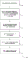
Fig. 4 illustrates an example of a process flow 400 for SRS under asymmetric eCA, in accordance with aspects of the present disclosure. Process flow 400 may include a base station 105-a and a UE 115-a, which may be examples of corresponding devices described with reference to fig. 1-2.
In step 405, the UE 115-c may transmit a capability indication (e.g., a number of UL CCs (e.g., carriers) that the UE 115-c is capable of supporting, antenna switching capabilities, etc.) to the base station 105. For example, the number of supported UL CCs may indicate a number of parallel UL transmissions that the UE 115-c is capable of supporting (e.g., a number of concurrent transmissions that the UE 115-c may make on different CCs).
In step 410, the base station 105-b may signal the CA configuration and the secondary UL configuration to the UE 115-c. The CA configuration may include CCs configured for UL data transmission, and the secondary UL configuration may include CCs configured for UL reference signal transmission (e.g., SRS, PRACH, etc.). Further, the CA configuration may include a carrier for DL transmission in addition to a carrier configured for UL transmission. The number of carriers configured for DL transmission may be greater than the number of carriers configured for UL transmission. The secondary UL configuration may be based on the CA configuration and the indication from step 405. In some cases, the CA configuration may include a secondary UL configuration. In other cases, the CA configuration may be separate from the secondary UL configuration.
In step 415-a, UE 115-c may transmit UL data on the UL CC in the CA and base station 105-b may receive the UL data.
In step 415-b, the UE 115-c may transmit an SRS using a CC in the assisted UL configuration signaled to the UE 115-c in step 410 and the base station 105-b may receive the SRS. The SRS may be periodic or aperiodic. The transmit antennas may be selected based on whether the SRS is periodic or aperiodic. Alternatively, at step 415-b, the UE 115-c may transmit a PRACH message using a CC in the secondary UL configuration and the base station 105-b may receive the PRACH message.
Steps 415-a and 415-b (e.g., parallel CC transmission) may be performed during the same TTI. Alternatively, the UE may switch between carriers to perform steps 415-a and 415-b (e.g., antenna switching for single CC transmission).
Fig. 5 illustrates a block diagram of a wireless device 500 supporting SRS under asymmetric eCA, in accordance with various aspects of the present disclosure. The wireless device 500 may be an example of aspects of the UE 115 described with reference to fig. 1 and 2. The wireless device 500 may include a receiver 505, a UE-assisted uplink manager 510, and a transmitter 515. The wireless device 500 may also include a processor. Each of these components may be in communication with each other.
The UE-assisted uplink manager 510 may communicate an indication of the UE capabilities in combination with the transmitter 515. The UE-assisted uplink manager may receive the CA configuration and the assisted UL configuration in combination with the receiver 505. The CA configuration may include one or more carriers configured for UL data transmission, and the secondary UL configuration includes one or more carriers configured for UL reference signal transmission. The UE-assisted uplink manager 510 may transmit the SRS using one or more carriers in the assisted UL configuration based on the CA configuration and the UE capabilities in combination with the transmitter 515. The UE-assisted uplink manager 510 may also be an example of aspects of the UE-assisted uplink manager 805 described with reference to fig. 8.
Fig. 6 illustrates a block diagram of a wireless device 600 that supports SRS under asymmetric ecas, in accordance with various aspects of the present disclosure. The wireless device 600 may be an example of aspects of the wireless device 500 or UE 115 described with reference to fig. 1, 2, and 5. Wireless device 600 may include a receiver 605, a UE-assisted uplink manager 610, and a transmitter 630. The wireless device 600 may also include a processor. Each of these components may be in communication with each other.
The UE-assisted uplink manager 610 may be an example of aspects of the UE-assisted uplink manager 510 described with reference to fig. 5. UE-assisted uplink manager 610 can include SRS component 615, capability indication component 620, and carrier configuration component 625. The UE-assisted uplink manager 610 may be an example of aspects of the UE-assisted uplink manager 805 described with reference to fig. 8.
In some cases, the one or more carriers configured for UL data transmission include at least one carrier configured for TDD. In some cases, the one or more carriers configured for UL data transmission comprise a carrier of the first TAG and the one or more carriers configured for UL reference signals comprise a carrier of the second TAG. In some cases, the CA configuration includes a secondary UL configuration. In some cases, the secondary UL configuration is different from the CA configuration. In some cases, the CA configuration is part of a dual connectivity configuration. In some cases, the CA configuration includes a set of PUCCH groups, and wherein the secondary UL corresponds to one PUCCH group of the set of PUCCH groups. In some cases, the CA configuration includes a first number of carriers configured for DL transmissions and a second number of carriers configured for UL transmissions, and wherein the first number is greater than the second number.
The transmitter 630 may transmit signals received from other components of the wireless device 600. In some examples, the transmitter 630 may be co-located with the receiver in a transceiver module. For example, the transmitter 630 may be an example of aspects of the transceiver 825 described with reference to fig. 8. The transmitter 630 may utilize a single antenna, or it may utilize multiple antennas.
Fig. 7 shows a block diagram of a UE-assisted uplink manager 700, which UE-assisted uplink manager 700 may be an example of a corresponding component of wireless device 500 or wireless device 600. That is, the UE-assisted uplink manager 700 may be an example of aspects of the UE-assisted uplink manager 510 or the UE-assisted uplink manager 610 described with reference to fig. 5 and 6. The UE-assisted uplink manager 700 may also be an example of aspects of the UE-assisted uplink manager 805 described with reference to fig. 8.
UE-assisted uplink manager 700 can include a UL data component 705, a SRS component 710, a switching symbol component 715, a rate matching component 720, a capability indication component 725, a RACH component 730, and a carrier configuration component 735. Each of these modules may be in communication with each other, directly or indirectly (e.g., via one or more buses).
In some examples, the handover symbol may be identified based on UE capabilities and may be signaled to the network. In some cases, a switching symbol may not be used in case of switching from UL data transmission to SRS transmission because the SRS is located in a later symbol of the subframe.
The carrier configuration component 735 may receive a second auxiliary configuration for a second TAG; a secondary UL configuration may be associated with the first TAG and receive a CA configuration and a secondary UL configuration. In some cases, carrier configuration component 735 may receive a TAG configuration in which SRS CCs and UL CCs belong to different TAG or PUCCH groups.
Fig. 8 illustrates a diagram of a system 800 that includes devices that support SRS under asymmetric eCA, in accordance with various aspects of the present disclosure. For example, system 800 may include UE 115-d, which may be an example of wireless device 500, wireless device 600, or UE 115 described with reference to fig. 1, 2, and 5 through 7.
UE 115-d may also include a UE secondary uplink manager 805, memory 810, processor 820, transceiver 825, antenna 830, and ECC module 835. Each of these modules may communicate with each other directly or indirectly (e.g., via one or more buses). The UE-assisted uplink manager 805 may be an example of the UE-assisted uplink manager described with reference to fig. 5 to 7.
The transceiver 825 may be in bidirectional communication with one or more networks via one or more antennas, wired or wireless links, as described herein. For example, the transceiver 825 may communicate bi-directionally with the base station 105 or the UE 115. The transceiver 825 may also include a modem to modulate packets and provide the modulated packets to an antenna for transmission, and to demodulate packets received from the antenna. In some cases, the wireless device may include a single antenna 830. However, in some cases, the device may have more than one antenna 830, which may be capable of concurrently transmitting or receiving multiple wireless transmissions.
The ECC module 835 may enable operations using ECCs, such as communications using shared or unlicensed spectrum, using reduced TTI or subframe durations, or using a large number of component carriers.
Fig. 9 illustrates a block diagram of a wireless device 900 supporting SRS under asymmetric eCA in accordance with various aspects of the disclosure. The wireless device 900 may be an example of aspects of the base station 105 described with reference to fig. 1 and 2. The wireless device 900 may include a receiver 905, a transmitter 910, and a base station assisted uplink manager 915. The wireless device 900 may also include a processor. Each of these components may be in communication with each other.
A receiver 905 may receive information such as packets, user data, or control information associated with various information channels (e.g., control channels, data channels, and information related to SRS under asymmetric eCA, etc.). Information may be passed to other components of the device. The receiver 905 may be an example of aspects of the transceiver 1225 described with reference to fig. 12.
The transmitter 910 may transmit signals received from other components of the wireless device 900. In some examples, the transmitter 910 may be co-located with a receiver in a transceiver module. For example, the transmitter 910 may be an example of aspects of the transceiver 1225 described with reference to fig. 12. The transmitter 910 may include a single antenna, or it may include multiple antennas.
The base station auxiliary uplink manager 915 may receive the indication of the UE capability in combination with the receiver 905, transmit the CA configuration and the auxiliary UL configuration for the UE in combination with the transmitter 910; the CA configuration may include one or more carriers configured for UL data transmission and the secondary UL configuration includes one or more carriers configured for UL reference signal transmission. The base station assisted uplink manager 915 can receive SRS using one or more carriers in the assisted UL configuration based on the CA configuration and UE capabilities in combination with the receiver 905. The base station assisted uplink manager 915 may also be an example of aspects of the base station assisted uplink manager 1205 described with reference to fig. 12.
Fig. 10 illustrates a block diagram of a wireless device 1000 supporting SRS under asymmetric eCA in accordance with various aspects of the present disclosure. The wireless device 1000 may be an example of aspects of the wireless device 900 or the base station 105 described with reference to fig. 1, 2, and 9. The wireless device 1000 may include a receiver 1005, a base station assisted uplink manager 1010, and a transmitter 1030. The wireless device 1000 may also include a processor. Each of these components may be in communication with each other.
The receiver 1005 may receive information, which may be communicated to other components of the device. The receiver 1005 may also perform the functions described with reference to the receiver 905 of fig. 9. The receiver 1005 may be an example of aspects of the transceiver 1225 described with reference to fig. 12.
The base station assisted uplink manager 1010 may be an example of aspects of the base station assisted uplink manager 915 described with reference to fig. 9. The base station assisted uplink manager 1010 can include a capability identification component 1015, an SRS component 1020, and a carrier configuration component 1025. The base station assisted uplink manager 1010 may be an example of aspects of the base station assisted uplink manager 1205 described with reference to fig. 12.
The capability identification component 1015 may receive, in combination with the receiver 1005, an indication of UE capabilities. SRS component 1020, in combination with receiver 1005, may receive SRS using one or more carriers in the secondary UL configuration based on the CA configuration and the UE capabilities.
The transmitter 1030 may transmit signals received from other components of the wireless device 1000. In some examples, the transmitter 1030 may be co-located with a receiver in a transceiver module. For example, the transmitter 1030 may be an example of aspects of the transceiver 1225 described with reference to fig. 12. The transmitter 1030 may utilize a single antenna, or it may utilize multiple antennas.
Fig. 11 shows a block diagram of a base station assisted uplink manager 1100, which base station assisted uplink manager 1100 may be an example of corresponding components of wireless device 900 or wireless device 1000. That is, the base station assisted uplink manager 1100 may be an example of aspects of the base station assisted uplink manager 915 or the base station assisted uplink manager 1010 described with reference to fig. 9 and 10. The base station assisted uplink manager 1100 may also be an example of aspects of the base station assisted uplink manager 1205 described with reference to fig. 12.
Base station assisted uplink manager 1100 can include UL data component 1105, handover symbol component 1110, capability identification component 1115, RACH component 1120, SRS component 1125, and carrier configuration component 1130. Each of these modules may communicate with each other directly or indirectly (e.g., via one or more buses).
The capability identification component 1115 may receive an indication of UE capabilities in combination with the receiver 905 or 1005. RACH component 1120 may receive PRACH messages on one or more carriers in a secondary UL configuration in combination with receiver 905 or 1005. SRS component 1125, in combination with receiver 905 or 1005, can receive SRS using one or more carriers in a secondary UL configuration based on CA configuration and UE capabilities.
A carrier configuration component 1130 may transmit the CA configuration and the secondary UL configuration for the UE in combination with the transmitter 910 or 1030; the CA configuration may include one or more carriers configured for UL data transmission, and the secondary UL configuration includes one or more carriers configured for UL reference signal transmission. The carrier configuration component 1130 may communicate a second secondary configuration for a second TAG in combination with the transmitter 910 or 1030, wherein the secondary UL configuration is associated with the first TAG.
Fig. 12 illustrates a diagram of a wireless system 1200 including devices supporting SRS under asymmetric eCA, in accordance with various aspects of the disclosure. For example, wireless system 1200 may include base station 105-d, which base station 105-d may be an example of wireless device 900, wireless device 1000, or base station 105 described with reference to fig. 1, 2, and 9 through 11. The base station 105-d may also include components for two-way voice and data communications, including components for transmitting communications and components for receiving communications. For example, a base station 105-d may communicate bi-directionally with one or more UEs 115.
The base station 105-d may also include a base station assisted uplink manager 1205, a memory 1210, a processor 1220, a transceiver 1225, an antenna 1230, a base station communications module 1235, and a network communications module 1240. Each of these modules may communicate with each other directly or indirectly (e.g., via one or more buses). The base station assisted uplink manager 1205 may be an example of the base station assisted uplink manager described with reference to fig. 9 to 11.
The transceiver 1225 may communicate bi-directionally with one or more networks via one or more antennas, wired or wireless links, as described herein. For example, the transceiver 1225 may communicate bi-directionally with the base station 105 or the UE 115. The transceiver 1225 may also include a modem to modulate packets and provide the modulated packets to an antenna for transmission, and to demodulate packets received from the antenna. In some cases, the wireless device may include a single antenna 1230. However, in some cases, the device may have more than one antenna 830, which may be capable of concurrently transmitting or receiving multiple wireless transmissions.
The base station communication module 1235 may manage communication with other base stations 105 and may include a controller or scheduler for controlling communication with the UE 115 in cooperation with the other base stations 105. For example, the base station communication module 1235 may coordinate scheduling of transmissions to the UE 115 for various interference mitigation techniques, such as beamforming or joint transmission. In some examples, the base station communication module-95 may provide an X2 interface within LTE/LTE-a wireless communication network technology to provide communication between base stations 105.
The network communications module 1240 may manage communications with the core network (e.g., via one or more wired backhaul links). For example, the network communications module 1240 may manage the communication of data communications for client devices (such as one or more UEs 115).
Fig. 13 shows a flow diagram illustrating a method 1300 for SRS under asymmetric eCA, in accordance with various aspects of the present disclosure. The operations of method 1300 may be implemented by a device, such as UE 115 described with reference to fig. 1 and 2, or a component thereof. For example, the operations of method 1300 may be performed by a UE-assisted uplink manager as described herein. In some examples, the UE 115 may execute a set of codes to control the functional elements of the device to perform the functions described below. Additionally or alternatively, the UE 115 may use dedicated hardware to perform aspects of the functions described below.
At block 1305, the UE 115 may transmit an indication of UE capabilities, as described herein with reference to fig. 2-4. In some examples, the operations of block 1305 may be performed by a capability indication component as described with reference to fig. 6 and 7.
At block 1310, UE 115 may receive signaling indicating a CA configuration and a secondary UL configuration, the CA configuration including one or more carriers configured for UL data transmission and the secondary UL configuration including one or more carriers configured for UL reference signal transmission, as described herein with reference to fig. 2-4. In certain examples, the operations of block 1310 may be performed by a carrier configuration component as described with reference to fig. 6 and 7.
At block 1315, the UE 115 may transmit the SRS using one or more carriers in the secondary UL configuration based on the CA configuration and the UE capabilities, as described herein with reference to fig. 2-4. In certain examples, the operations of block 1315 may be performed by the SRS component as described with reference to fig. 6 and 7.
Fig. 14 shows a flow diagram illustrating a method 1400 for SRS under asymmetric eCA, in accordance with various aspects of the present disclosure. The operations of method 1400 may be implemented by a device, such as UE 115 described with reference to fig. 1 and 2, or a component thereof. For example, the operations of method 1400 may be performed by a UE-assisted uplink manager as described herein. In some examples, the UE 115 may execute a set of codes to control the functional elements of the device to perform the functions described below. Additionally or alternatively, the UE 115 may use dedicated hardware to perform aspects of the functions described below.
At block 1405, the UE 115 may transmit an indication of the UE capabilities, as described herein with reference to fig. 2 through 4. In some examples, the operations of block 1405 may be performed by the capability indication component as described with reference to fig. 6 and 7.
At block 1410, the UE 115 may receive signaling indicating a CA configuration and a secondary UL configuration, the CA configuration including one or more carriers configured for UL data transmission and the secondary UL configuration including one or more carriers configured for UL reference signal transmission, as described herein with reference to fig. 2-4. In certain examples, the operations of block 1410 may be performed by a carrier configuration component as described with reference to fig. 6 and 7.
At block 1415, the UE 115 may transmit the SRS using one or more carriers in the secondary UL configuration based on the CA configuration and the UE capabilities, as described herein with reference to fig. 2-4. In certain examples, the operations of block 1415 may be performed by the SRS component as described with reference to fig. 6 and 7.
At block 1420, the UE 115 may transmit the UL data transmission on one or more carriers configured for UL data transmission, wherein the UL data is transmitted during the same TTI as the SRS, as described herein with reference to fig. 2-4. In certain examples, the operations of block 1420 may be performed by the UL data component as described with reference to fig. 6 and 7.
Fig. 15 shows a flow diagram illustrating a method 1500 for SRS under asymmetric eCA, in accordance with various aspects of the present disclosure. The operations of method 1500 may be implemented by a device, such as UE 115 described with reference to fig. 1 and 2, or a component thereof. For example, the operations of method 1500 may be performed by a UE-assisted uplink manager as described herein. In some examples, the UE 115 may execute a set of codes to control the functional elements of the device to perform the functions described below. Additionally or alternatively, the UE 115 may use dedicated hardware to perform aspects of the functions described below.
At block 1505, the UE 115 may transmit an indication of the UE capabilities, as described herein with reference to fig. 2-4. In some examples, the operations of block 1505 may be performed by the capability indication component as described with reference to fig. 6 and 7.
At block 1510, the UE 115 may receive signaling indicating a CA configuration and a secondary UL configuration, the CA configuration including one or more carriers configured for UL data transmission, and the secondary UL configuration including one or more carriers configured for UL reference signal transmission, as described herein with reference to fig. 2-4. In certain examples, the operations of block 1510 may be performed by a carrier configuration component as described with reference to fig. 6 and 7.
At block 1515, the UE 115 may transmit the SRS using one or more carriers in the secondary UL configuration based on the CA configuration and the UE capabilities, as described herein with reference to fig. 2-4. In certain examples, the operations of block 1515 may be performed by the SRS component as described with reference to fig. 6 and 7.
At block 1520, the UE 115 may transmit additional SRS, where the SRS is transmitted using the first set of antennas and the additional SRS is transmitted using the second set of antennas, as described herein with reference to fig. 2 through 4. In certain examples, the operations of block 1520 may be performed by the SRS component as described with reference to fig. 6 and 7.
Fig. 16 shows a flow diagram illustrating a method 1600 for SRS under asymmetric eCA, in accordance with various aspects of the present disclosure. The operations of method 1600 may be implemented by a device, such as UE 115 described with reference to fig. 1 and 2, or a component thereof. For example, the operations of method 1600 may be performed by a UE-assisted uplink manager as described herein. In some examples, the UE 115 may execute a set of codes to control the functional elements of the device to perform the functions described below. Additionally or alternatively, the UE 115 may use dedicated hardware to perform aspects of the functions described below.
At block 1605, the UE 115 may transmit an indication of the UE capabilities, as described herein with reference to fig. 2-4. In some examples, the operations of block 1605 may be performed by a capability indication component as described with reference to fig. 6 and 7.
At block 1610, the UE 115 may receive signaling indicating a CA configuration and a secondary UL configuration, the CA configuration including one or more carriers configured for UL data transmission and the secondary UL configuration including one or more carriers configured for UL reference signal transmission, as described herein with reference to fig. 2-4. In certain examples, the operations of block 1610 may be performed by a carrier configuration component as described with reference to fig. 6 and 7.
At block 1615, the UE 115 may transmit the SRS using one or more carriers in the secondary UL configuration based on the CA configuration and the UE capabilities, as described herein with reference to fig. 2-4. In certain examples, the operations of block 1615 may be performed by the SRS component as described with reference to fig. 6 and 7.
At block 1620, the UE 115 may identify one or more switching symbols based on the transmitted SRS or the SRS location, or both, as described herein with reference to fig. 2 through 4. In some examples, the operations of block 1620 may be performed by a switch symbol component as described with reference to fig. 6 and 7.
At block 1625, the UE 115 may rate match or puncture the UL data transmission based on the one or more switching symbols, as described herein with reference to fig. 2-4. In certain examples, the operations of block 1625 may be performed by a rate matching component as described with reference to fig. 6 and 7.
At block 1630, the UE 115 may initiate UL data transmission during a symbol period after the one or more switching symbols, as described herein with reference to fig. 2 through 4. In certain examples, the operations of block 1630 may be performed by the UL data component as described with reference to fig. 6 and 7.
Fig. 17 shows a flow diagram illustrating a method 1700 for SRS under asymmetric eCA, in accordance with various aspects of the present disclosure. The operations of method 1700 may be implemented by a device, such as UE 115 described with reference to fig. 1 and 2, or a component thereof. For example, the operations of method 1700 may be performed by a UE-assisted uplink manager as described herein. In some examples, the UE 115 may execute a set of codes to control the functional elements of the device to perform the functions described below. Additionally or alternatively, the UE 115 may use dedicated hardware to perform aspects of the functions described below.
At block 1705, the UE 115 may transmit an indication of UE capabilities, as described herein with reference to fig. 2 through 4. In some examples, the operations of block 1705 may be performed by a capability indication component as described with reference to fig. 6 and 7.
At block 1710, the UE 115 may receive signaling indicating a CA configuration including one or more carriers configured for UL data transmission and a secondary UL configuration including one or more carriers configured for UL reference signal transmission, as described herein with reference to fig. 2-4. In certain examples, the operations of block 1710 may be performed by a carrier configuration component as described with reference to fig. 6 and 7.
At block 1715, the UE 115 may transmit the SRS using one or more carriers in the secondary UL configuration based on the CA configuration and the UE capabilities, as described herein with reference to fig. 2-4. In certain examples, the operations of block 1715 may be performed by the SRS component as described with reference to fig. 6 and 7.
At block 1720, the UE 115 may transmit a PRACH message on one or more carriers in the secondary UL configuration, as described herein with reference to fig. 2 through 4. In certain examples, the operations of block 1720 may be performed by a RACH assembly as described with reference to fig. 6 and 7.
Fig. 18 shows a flow diagram illustrating a method 1800 for SRS under asymmetric eCA, in accordance with various aspects of the present disclosure. The operations of method 1800 may be implemented by a device, such as base station 105 described with reference to fig. 1 and 2, or a component thereof. For example, the operations of method 1800 may be performed by a base station assisted uplink manager as described herein. In some examples, the base station 105 may execute a set of codes for controlling the functional elements of the apparatus to perform the functions described below. Additionally or alternatively, the base station 105 may use dedicated hardware to perform aspects of the functions described below.
At block 1805, the base station 105 may receive an indication of UE capabilities, as described herein with reference to fig. 2 through 4. In some examples, the operations of block 1805 may be performed by a capability identification component as described with reference to fig. 10 and 11.
At block 1810, the base station 105 may transmit signaling indicating a CA configuration and a secondary UL configuration for the UE, the CA configuration comprising one or more carriers configured for UL data transmission and the secondary UL configuration comprising one or more carriers configured for UL reference signal transmission, as described herein with reference to fig. 2-4. In certain examples, the operations of block 1810 may be performed by a carrier configuration component as described with reference to fig. 10 and 11.
At block 1815, the base station 105 may receive the SRS using one or more carriers in the secondary UL configuration based on the CA configuration and the UE capabilities, as described herein with reference to fig. 2-4. In certain examples, the operations of block 1815 may be performed by the SRS component as described with reference to fig. 10 and 11.
Fig. 19 shows a flow diagram illustrating a method 1900 for SRS under asymmetric ecas, in accordance with various aspects of the present disclosure. The operations of method 1900 may be implemented by a device, such as UE 115 described with reference to fig. 1 and 2 or a component thereof. For example, the operations of method 1900 may be performed by a UE-assisted uplink manager as described herein. In some examples, the UE 115 may execute a set of codes to control the functional elements of the device to perform the functions described below. Additionally or alternatively, the UE 115 may use dedicated hardware to perform aspects of the functions described below.
At block 1905, the UE 115 may transmit an indication of the UE capabilities, as described herein with reference to fig. 2-4. In some examples, the operations of block 1905 may be performed by a capability indication component as described with reference to fig. 6 and 7.
At block 1910, the UE 115 may receive signaling indicating a CA configuration and a secondary UL configuration. The CA configuration may include one or more carriers configured for UL data transmission and the secondary UL configuration includes one or more carriers configured for UL reference signal transmission, and the CA configuration may include a first number of carriers configured for DL transmission and a second number of carriers configured for UL transmission, wherein the first number is greater than the second number such that there is asymmetry in the UL CC and the DL CC in the CA configuration, as described herein with reference to fig. 2-4. In certain examples, the operations of block 1910 may be performed by a carrier configuration component as described with reference to fig. 6 and 7.
At block 1915, the UE 115 may transmit the SRS using one or more carriers in the secondary UL configuration based on the CA configuration and the UE capabilities, as described herein with reference to fig. 2-4. In certain examples, the operations of block 1915 may be performed by the SRS component as described with reference to fig. 6 and 7.
It should be noted that these methods describe possible implementations, and that the operations and steps may be rearranged or otherwise modified so that other implementations are possible. In some examples, aspects from two or more methods may be combined. For example, aspects of each method may include steps or aspects of the other methods, or other steps or techniques described herein. Thus, aspects of the present disclosure may provide SRS under eCA, which may be an alternative term for CA or other multi-carrier configurations with aggregated CCs.
The description herein is provided to enable any person skilled in the art to make or use the present disclosure. Various modifications to the disclosure will be readily apparent to those skilled in the art, and the generic principles defined herein may be applied to other variations without departing from the scope of the disclosure. Thus, the disclosure is not intended to be limited to the examples and designs described herein but is to be accorded the widest scope consistent with the principles and novel features disclosed herein.
The functions described herein may be implemented in hardware, software executed by a processor, firmware, or any combination thereof. If implemented in software executed by a processor, the functions may be stored on or transmitted over as one or more instructions or code on a computer-readable medium. Other examples and implementations are within the scope of the disclosure and the following claims. For example, due to the nature of software, the functions described herein may be implemented using software executed by a processor, hardware, firmware, hard-wired, or any combination thereof. Features that implement functions may also be physically located at various locations, including being distributed such that portions of functions are implemented at different physical locations. In addition, as used herein, including in the claims, "or" as used in a list of items (e.g., a list of items accompanied by a phrase such as "at least one of" or "one or more of") indicates an inclusive list, such that, for example, a list of at least one of A, B or C means a or B or C or AB or AC or BC or ABC (i.e., a and B and C).
Computer-readable media includes both non-transitory computer storage media and communication media, including any medium that facilitates transfer of a computer program from one place to another. Non-transitory storage media may be any available media that can be accessed by a general purpose or special purpose computer. By way of example, and not limitation, non-transitory computer-readable media can comprise RAM, ROM, electrically erasable programmable read-only memory (EEPROM), Compact Disk (CD) ROM or other optical disk storage, magnetic disk storage or other magnetic storage devices, or any other non-transitory medium that can be used to carry or store desired program code means in the form of instructions or data structures and that can be accessed by a general-purpose or special-purpose computer, or a general-purpose or special-purpose processor. Any connection is properly termed a computer-readable medium. For example, if the software is transmitted from a web site, server, or other remote source using a coaxial cable, fiber optic cable, twisted pair, Digital Subscriber Line (DSL), or wireless technologies such as infrared, radio, and microwave, then the coaxial cable, fiber optic cable, twisted pair, DSL, or wireless technologies such as infrared, radio, and microwave are included in the definition of medium. Disk (disk) and disc (disc), as used herein, includes CD, laser disc, optical disc, Digital Versatile Disc (DVD), floppy disk and blu-ray disc where disks usually reproduce data magnetically, while discs reproduce data optically with lasers. Combinations of the above are also included within the scope of computer-readable media.
The techniques described herein may be used for various wireless communication systems such as CDMA, TDMA, FDMA, OFDMA, single-carrier frequency division multiple access (SC-FDMA), and other systems. The terms "system" and "network" are often used interchangeably. A CDMA system may implement a radio technology such as CDMA2000, Universal Terrestrial Radio Access (UTRA), and so on. CDMA2000 covers IS2000, IS-95 and IS-856 standards. IS-2000 releases 0 and A are often referred to as CDMA 20001X, 1X, etc. IS-856(TIA-856) IS often referred to as CDMA 20001 xEV-DO, High Rate Packet Data (HRPD), etc. UTRA includes wideband CDMA (wcdma) and other CDMA variants. TDMA systems may implement radio technologies such as global system for mobile communications (GSM). The OFDMA system may implement radio technologies such as Ultra Mobile Broadband (UMB), evolved UTRA (E-UTRA), IEEE 802.11, IEEE 802.16(WiMAX), IEEE 802.20, Flash-OFDM, etc. UTRA and E-UTRA are part of the Universal Mobile Telecommunications System (UMTS). 3GPP LTE and LTE-advanced (LTE-A) are new UMTS releases that use E-UTRA. UTRA, E-UTRA, UMTS, LTE-a, and GSM are described in literature from an organization named "third Generation partnership project" (3 GPP). CDMA2000 and UMB are described in documents from an organization named "third generation partnership project 2" (3GPP 2). The techniques described herein may be used for both the above-mentioned systems and radio technologies, as well as for other systems and radio technologies. However, the description herein describes an LTE system for purposes of example, and LTE terminology is used in much of the description above, but the techniques may also be applied to applications other than LTE applications.
In an LTE/LTE-a network (including the networks described herein), the term evolved node B (eNB) may be used generically to describe a base station. One or more wireless communication systems described herein may include heterogeneous LTE/LTE-a networks, where different types of enbs provide coverage for various geographic regions. For example, each eNB or base station may provide communication coverage for a macro cell, a small cell, or other type of cell. The term "cell" is a 3GPP term that can be used to describe a base station, a carrier or CC associated with a base station, or a coverage area (e.g., sector, etc.) of a carrier or base station, depending on the context.
A base station may include, or may be referred to by those skilled in the art as, a base transceiver station, a radio base station, an Access Point (AP), a radio transceiver, a node B, an evolved node B (eNB), a home node B, a home evolved node B, or some other suitable terminology. The geographic coverage area of a base station may be partitioned into sectors that form only a portion of the coverage area. One or several wireless communication systems described herein may include different types of base stations (e.g., macro or small cell base stations). The UEs described herein may be capable of communicating with various types of base stations and network equipment, including macro enbs, small cell enbs, relay base stations, and the like. There may be overlapping geographic coverage areas of different technologies. In some cases, different coverage areas may be associated with different communication technologies. In some cases, the coverage area of one communication technology may overlap with the coverage area associated with another technology. Different technologies may be associated with the same base station or different base stations.
A macro cell generally covers a relatively large geographic area (e.g., an area with a radius of several kilometers) and may allow unrestricted access by UEs with service subscriptions with the network provider. Small cells are low power base stations that may operate in the same or different (e.g., licensed, unlicensed, etc.) frequency bands as macro cells as compared to macro cells. According to various examples, a small cell may include a picocell, a femtocell, and a microcell. Picocells, for example, may cover a small geographic area and may allow unrestricted access by UEs with service subscriptions with the network provider. A femtocell may also cover a smaller geographic area (e.g., a residence) and may be provided access restricted by UEs associated with the femtocell (e.g., UEs in a Closed Subscriber Group (CSG), UEs of users in the residence, etc.). The eNB for a macro cell may be referred to as a macro eNB. An eNB for a small cell may be referred to as a small cell eNB, pico eNB, femto eNB, or home eNB. An eNB may support one or more (e.g., two, three, four, etc.) cells (e.g., CCs). The UE may be capable of communicating with various types of base stations and network equipment, including macro enbs, small cell enbs, relay base stations, and the like.
One or more of the wireless communication systems described herein may support synchronous or asynchronous operation. For synchronous operation, each base station may have similar frame timing, and transmissions from different base stations may be approximately aligned in time. For asynchronous operation, each base station may have different frame timing, and transmissions from different base stations may not be aligned in time. The techniques described herein may be used for synchronous or asynchronous operations.
The DL transmissions described herein may also be referred to as forward link transmissions, while the UL transmissions may also be referred to as reverse link transmissions. Each of the communication links described herein (including, for example, the wireless communication systems 100 and 200 of fig. 1 and 2) may include one or more carriers, where each carrier may be a signal (e.g., a waveform signal of a different frequency) made up of multiple subcarriers. Each modulated signal may be sent on a different subcarrier and may carry control information (e.g., reference signals, control channels, etc.), overhead information, user data, and so on. Communication links described herein (e.g., communication link 125 of fig. 1) may communicate bi-directional communications using FDD (e.g., using paired spectrum resources) or TDD operation (e.g., using unpaired spectrum resources). A frame structure (e.g., frame structure type 1) for FDD and a frame structure (e.g., frame structure type 2) for TDD may be defined.
Thus, aspects of the present disclosure may provide SRS under asymmetric ecas. It should be noted that these methods describe possible implementations, and that the operations and steps may be rearranged or otherwise modified so that other implementations are possible. In some examples, aspects from two or more methods may be combined.
The various illustrative blocks and modules described in connection with the disclosure herein may be implemented or performed with a general purpose processor, a Digital Signal Processor (DSP), an ASIC, a Field Programmable Gate Array (FPGA) or other programmable logic device, discrete gate or transistor logic, discrete hardware components, or any combination thereof designed to perform the functions described herein. A general purpose processor may be a microprocessor, but in the alternative, the processor may be any conventional processor, controller, microcontroller, or state machine. A processor may also be implemented as a combination of computing devices (e.g., a combination of a DSP and a microprocessor, a plurality of microprocessors, one or more microprocessors in conjunction with a DSP core, or any other such configuration). Thus, the functions described herein may be performed by one or more other processing units (or cores) on at least one Integrated Circuit (IC). In various examples, different types of ICs (e.g., structured/platform ASICs, FPGAs, or another half-custom IC) may be used that may be programmed in any manner known in the art. The functions of each unit may also be implemented, in whole or in part, with instructions embodied in a memory, formatted to be executed by one or more general or special purpose processors.
In the drawings, similar components or features may have the same reference numerals. Further, various components of the same type may be distinguished by following the reference label by a dash and a second label that distinguishes among the similar components. If only the first reference label is used in the specification, the description is applicable to any one of the similar components having the same first reference label irrespective of the second reference label.
Claims (26)
1. A method for wireless communication, comprising:
transmitting an indication of a User Equipment (UE) capability, wherein the UE capability comprises at least an Uplink (UL) Carrier Aggregation (CA) capability of the UE;
receiving a CA configuration and a secondary UL configuration, the CA configuration comprising one or more carriers configured for UL data transmissions and the secondary UL configuration comprising one or more carriers configured for UL reference signal transmissions;
transmitting a Sounding Reference Signal (SRS) using the one or more carriers of the secondary UL configuration based on the CA configuration and the UL CA capability of the UE;
identifying one or more switching symbols based at least in part on a position of the SRS relative to other symbols of a subframe;
puncturing an UL data transmission based at least in part on the one or more switching symbols; and
transmitting the UL data transmission using the one or more carriers configured for UL data transmission during a symbol period following the one or more switching symbols.
2. The method of claim 1, wherein the CA configuration comprises a first number of carriers configured for Downlink (DL) transmission, wherein the first number is greater than a second number of the one or more carriers configured for UL data transmission.
3. The method of claim 1, wherein the indication of UE capability comprises an indication of a switching time associated with tuning between a carrier configured for UL data transmission and a carrier configured for UL reference signal transmission, and the one or more switching symbols are based at least in part on the switching time.
4. The method of claim 1, wherein the UL data transmission on the one or more carriers configured for UL data transmission is transmitted during a same Transmission Time Interval (TTI) as the SRS.
5. The method of claim 1, wherein the one or more carriers configured for UL data transmission comprise at least one carrier configured for Time Division Duplex (TDD).
6. The method of claim 1, further comprising:
transmitting an additional SRS, wherein the SRS are transmitted using a first set of antennas and the additional SRS are transmitted using a second set of antennas.
7. The method of claim 6, wherein the first set of antennas is selected for transmission on one or more carriers used for the SRS and the second set of antennas is selected for transmission on additional carriers used for the additional SRS.
8. The method of claim 6, wherein the SRS is a periodic SRS or an aperiodic SRS, and the additional SRS is a periodic SRS or an aperiodic SRS, and wherein the first set of antennas is selected based at least in part on the SRS being a periodic SRS, and the second set of antennas is selected based at least in part on the additional SRS being an aperiodic SRS.
9. The method of claim 8, further comprising:
receiving Radio Resource Control (RRC) signaling or Downlink Control Information (DCI), wherein the first set of antennas or the second set of antennas is selected based at least in part on the RRC signaling or the DCI.
10. The method of claim 1, further comprising:
transmitting a Physical Random Access Channel (PRACH) message on one or more carriers in the secondary UL configuration.
11. The method of claim 1, further comprising:
receiving a second secondary configuration for a second Timing Adjustment Group (TAG), wherein the secondary UL configuration is associated with the first TAG.
12. The method of claim 1, wherein the CA configuration comprises the secondary UL configuration.
13. The method of claim 1, wherein the secondary UL configuration is different from the CA configuration.
14. The method of claim 1, wherein the CA configuration is part of a dual connectivity configuration.
15. The method of claim 1, wherein the one or more carriers configured for UL data transmission comprise a carrier of a first Timing Adjustment Group (TAG) and the one or more carriers configured for UL reference signals comprise a carrier of a second TAG.
16. A method for wireless communication, comprising:
receiving an indication of a User Equipment (UE) capability, wherein the UE capability comprises at least an Uplink (UL) Carrier Aggregation (CA) capability of the UE;
transmitting a CA configuration and a secondary UL configuration for the UE, the CA configuration comprising one or more carriers configured for UL data transmissions by the UE and the secondary UL configuration comprising one or more carriers configured for UL reference signal transmissions by the UE;
receive a Sounding Reference Signal (SRS) using the one or more carriers of the secondary UL configuration based on the CA configuration and the UL CA capability of the UE;
identifying one or more switching symbols based at least in part on a position of the SRS relative to other symbols of a subframe; and
receiving a UL data transmission from the UE on the one or more carriers configured for UL data transmissions, wherein the UL data transmission from the UE is received during a symbol period after the one or more switching symbols.
17. The method of claim 16, wherein the CA configuration comprises a first number of carriers configured for Downlink (DL) transmission, wherein the first number is greater than a second number of the one or more carriers configured for UL data transmission.
18. The method of claim 16, wherein the UL data transmission on the one or more carriers configured for UL data transmission is received during a same Transmission Time Interval (TTI) as the SRS.
19. The method of claim 16, wherein the indication of UE capability comprises an indication of a switching time associated with tuning between a carrier configured for UL data transmission and a carrier configured for UL reference signal transmission, and the one or more switching symbols are based at least in part on the switching time.
20. The method of claim 16, further comprising:
receiving a Physical Random Access Channel (PRACH) message from the UE on one or more carriers in the secondary UL configuration.
21. The method of claim 16, further comprising:
communicating a second assistance configuration for a second Timing Adjustment Group (TAG), wherein the assistance UL configuration is associated with the first TAG.
22. A mobile device for wireless communication, comprising:
a processor;
a memory coupled to the processor; and
instructions stored in the memory and operable when executed by the processor to cause the mobile device to:
transmitting an indication of mobile device capabilities, wherein the mobile device capabilities include at least Uplink (UL) Carrier Aggregation (CA) capabilities of the mobile device;
receiving a CA configuration and a secondary UL configuration, the CA configuration comprising one or more carriers configured for UL data transmissions and the secondary UL configuration comprising one or more carriers configured for UL reference signal transmissions;
transmitting a Sounding Reference Signal (SRS) on the one or more carriers of the secondary UL configuration based on the CA configuration and the UL CA capability of the mobile device;
identifying one or more switching symbols based at least in part on a position of the SRS relative to other symbols of a subframe;
puncturing an UL data transmission based at least in part on the one or more switching symbols; and
transmitting the UL data transmission using the one or more carriers configured for UL data transmission during a symbol period following the one or more switching symbols.
23. The mobile device of claim 22, wherein the CA configuration comprises a first number of carriers configured for Downlink (DL) transmission, wherein the first number is greater than a second number of the one or more carriers configured for UL data transmission.
24. The mobile device of claim 22, wherein the instructions are executable by the processor to cause the mobile device to:
transmitting the UL data transmission on the one or more carriers configured for UL data transmissions during a same Transmission Time Interval (TTI) as the SRS.
25. A network device for wireless communication in a system, comprising:
a processor;
a memory coupled to the processor; and
instructions stored in the memory and operable when executed by the processor to cause the network device to:
receiving an indication of a User Equipment (UE) capability, wherein the UE capability comprises at least an Uplink (UL) Carrier Aggregation (CA) capability of the UE;
transmitting a CA configuration and a secondary UL configuration for the UE, the CA configuration comprising one or more carriers configured for UL data transmissions and the secondary UL configuration comprising one or more carriers configured for UL reference signal transmissions;
receive a Sounding Reference Signal (SRS) on the one or more carriers of the secondary UL configuration based on the CA configuration and the UL CA capability of the UE;
identifying one or more switching symbols based at least in part on a position of the SRS relative to other symbols of a subframe; and
receiving a UL data transmission from the UE on the one or more carriers configured for UL data transmissions, wherein the UL data transmission from the UE is received during a symbol period after the one or more switching symbols.
26. The network device of claim 25, wherein the CA configuration comprises a first number of carriers configured for Downlink (DL) transmission, wherein the first number is greater than a second number of the one or more carriers configured for UL data transmission.
Priority Applications (1)
| Application Number | Priority Date | Filing Date | Title |
|---|---|---|---|
| CN202111192623.XA CN113765644B (en) | 2016-03-24 | 2017-03-24 | Sounding reference signal transmission for carrier aggregation |
Applications Claiming Priority (5)
| Application Number | Priority Date | Filing Date | Title |
|---|---|---|---|
| US201662313100P | 2016-03-24 | 2016-03-24 | |
| US62/313,100 | 2016-03-24 | ||
| US15/467,459 US10735156B2 (en) | 2016-03-24 | 2017-03-23 | Sounding reference signal transmission for enhanced carrier aggregation |
| US15/467,459 | 2017-03-23 | ||
| PCT/US2017/023992 WO2017165751A1 (en) | 2016-03-24 | 2017-03-24 | Sounding reference signal transmission for carrier aggregation |
Related Child Applications (1)
| Application Number | Title | Priority Date | Filing Date |
|---|---|---|---|
| CN202111192623.XA Division CN113765644B (en) | 2016-03-24 | 2017-03-24 | Sounding reference signal transmission for carrier aggregation |
Publications (2)
| Publication Number | Publication Date |
|---|---|
| CN108886443A CN108886443A (en) | 2018-11-23 |
| CN108886443B true CN108886443B (en) | 2021-11-16 |
Family
ID=59898971
Family Applications (2)
| Application Number | Title | Priority Date | Filing Date |
|---|---|---|---|
| CN201780018113.6A Active CN108886443B (en) | 2016-03-24 | 2017-03-24 | Sounding reference signal transmission for carrier aggregation |
| CN202111192623.XA Active CN113765644B (en) | 2016-03-24 | 2017-03-24 | Sounding reference signal transmission for carrier aggregation |
Family Applications After (1)
| Application Number | Title | Priority Date | Filing Date |
|---|---|---|---|
| CN202111192623.XA Active CN113765644B (en) | 2016-03-24 | 2017-03-24 | Sounding reference signal transmission for carrier aggregation |
Country Status (9)
| Country | Link |
|---|---|
| US (1) | US10735156B2 (en) |
| EP (2) | EP3731452B1 (en) |
| JP (1) | JP6888022B2 (en) |
| KR (1) | KR102537041B1 (en) |
| CN (2) | CN108886443B (en) |
| BR (1) | BR112018069254A2 (en) |
| ES (1) | ES2827009T3 (en) |
| RU (1) | RU2739058C2 (en) |
| WO (1) | WO2017165751A1 (en) |
Families Citing this family (24)
| Publication number | Priority date | Publication date | Assignee | Title |
|---|---|---|---|---|
| CN113365236A (en) * | 2016-04-01 | 2021-09-07 | 华为技术有限公司 | Method, user equipment, base station and system for transmitting uplink signals among multiple carriers |
| JP6677825B2 (en) * | 2016-05-13 | 2020-04-08 | 華為技術有限公司Huawei Technologies Co.,Ltd. | Uplink reference signal transmission method, uplink reference signal reception method and apparatus |
| WO2018060538A1 (en) * | 2016-09-27 | 2018-04-05 | Nokia Technologies Oy | Multi-cell allocation |
| WO2018069311A1 (en) * | 2016-10-11 | 2018-04-19 | Telefonaktiebolaget Lm Ericsson (Publ) | Methods and apparatus for adapting srs switching accounting for measurement procedure |
| US20180132242A1 (en) * | 2016-11-04 | 2018-05-10 | Mediatek Inc. | Grouping of serving cells with shortened transmission time intervals |
| CN107396450B (en) * | 2017-07-19 | 2020-02-14 | 上海华为技术有限公司 | Cross-standard scheduling method and base station |
| CN109474400B (en) | 2017-09-08 | 2021-07-20 | 华为技术有限公司 | Communication method, network equipment and terminal equipment |
| KR20190039928A (en) * | 2017-10-02 | 2019-04-16 | 엘지전자 주식회사 | A method and an apparatus for transmitting an uplink in a dual connection between LTE and NR |
| KR102456001B1 (en) * | 2017-11-16 | 2022-10-19 | 삼성전자주식회사 | Method and apparatus for transmitting and receiving data on uplink carriers in wirelss communication system |
| US11088791B2 (en) | 2018-05-21 | 2021-08-10 | Qualcomm Incorporated | Choosing an SRS resource set when multiple sets are configured |
| CN110650485B (en) * | 2018-06-26 | 2021-02-19 | 维沃移动通信有限公司 | Antenna switching transmission mode indication method for SRS, terminal equipment and network equipment |
| WO2020009511A1 (en) | 2018-07-04 | 2020-01-09 | 엘지전자 주식회사 | Method for performing uplink transmission in wireless communication system, and device therefor |
| US11343824B2 (en) | 2018-08-01 | 2022-05-24 | Qualcomm Incorporated | Carrier switching and antenna switching for a target carrier combination |
| CN110933715B (en) * | 2018-09-20 | 2021-11-05 | 大唐移动通信设备有限公司 | Method, device and equipment for acquiring and providing positioning assistance data |
| CN110958091B (en) * | 2018-09-26 | 2022-06-07 | 中国移动通信有限公司研究院 | Configuration method, base station and terminal for uplink SRS antenna transmission |
| US10848209B2 (en) | 2018-10-09 | 2020-11-24 | Qualcomm Incorporated | Sounding reference signal (SRS) switching capability and configuration |
| CN111757478B (en) * | 2019-03-28 | 2023-11-14 | 华为技术有限公司 | Method, device and system for reporting SRS (sounding reference Signal) capability |
| EP3955503B1 (en) * | 2019-05-10 | 2023-08-02 | LG Electronics Inc. | Method and device for transmitting and receiving sounding reference signal in wireless communication system |
| CN112448800A (en) * | 2019-08-30 | 2021-03-05 | 华为技术有限公司 | SRS transmission method and device |
| CN114342519A (en) * | 2019-09-30 | 2022-04-12 | 华为技术有限公司 | Communication method and device |
| CN112787779B (en) * | 2019-11-07 | 2022-10-04 | 华为技术有限公司 | Communication method and user equipment |
| US20210144569A1 (en) * | 2019-11-08 | 2021-05-13 | Qualcomm Incorporated | Indication of user equipment capability for beam failure detection and beam management |
| US11632754B2 (en) * | 2020-02-06 | 2023-04-18 | Qualcomm Incorporated | Support of multiple SRS in the same subframe |
| CN113271178B (en) * | 2020-02-14 | 2023-03-31 | 华为技术有限公司 | User equipment capacity transmission method, information transmission method and related products |
Citations (3)
| Publication number | Priority date | Publication date | Assignee | Title |
|---|---|---|---|---|
| CN101771435A (en) * | 2009-01-05 | 2010-07-07 | 大唐移动通信设备有限公司 | Multi-carrier aggregation system and method thereof for selecting uplink reference signals |
| CN102185642A (en) * | 2011-05-12 | 2011-09-14 | 电信科学技术研究院 | Method, system and equipment for transmitting configuration information and selecting transmission antenna |
| US20120002643A1 (en) * | 2009-03-13 | 2012-01-05 | Lg Electronics Inc | Handover performed in consideration of uplink/downlink component carrier setup |
Family Cites Families (20)
| Publication number | Priority date | Publication date | Assignee | Title |
|---|---|---|---|---|
| DE60138790D1 (en) * | 2000-09-25 | 2009-07-09 | Konica Corp | Organic electroluminescent element and organic electroluminescent material used therefor |
| US8526374B2 (en) * | 2008-09-12 | 2013-09-03 | Qualcomm Incorporated | Physical random access channel (PRACH) transmission in multicarrier operation |
| EP2522190B1 (en) * | 2010-01-08 | 2018-02-07 | Sharp Kabushiki Kaisha | Mobile communication method and system for sounding reference signal transmission, and base station, user equipment and integrated circuit therein |
| WO2011142608A2 (en) * | 2010-05-12 | 2011-11-17 | 엘지전자 주식회사 | Method for transmitting an srs-triggering-based srs in a wireless communication system |
| US8855053B2 (en) * | 2010-06-18 | 2014-10-07 | Mediatek Inc. | Sounding mechanism and configuration under carrier aggregation |
| US9131457B2 (en) * | 2010-08-12 | 2015-09-08 | Samsung Electronics Co., Ltd. | Apparatus and method for transmission of uplink sounding reference signals in a wireless network |
| CA2812073C (en) * | 2010-09-17 | 2017-05-30 | Research In Motion Limited | Sounding reference signal transmission in carrier aggregation |
| US9350506B2 (en) * | 2010-09-30 | 2016-05-24 | Qualcomm Incorporated | Aperiodic SRS for carrier aggregation |
| MX2013012566A (en) * | 2011-05-02 | 2013-11-21 | Ericsson Telefon Ab L M | Method and apparatus for prohibiting sounding reference signal transmission newly activated secondary cells in a wireless communication system. |
| US8934350B2 (en) * | 2011-05-23 | 2015-01-13 | Qualcomm Incorporated | Channel state information feedback for carrier aggregation with flexible carrier configurations |
| US20130010659A1 (en) * | 2011-07-08 | 2013-01-10 | Qualcomm Incorporated | Sounding reference signals in asymmetric carrier aggregation |
| US9288799B2 (en) * | 2011-07-24 | 2016-03-15 | Lg Electronics Inc. | Method and apparatus for selecting carrier in wireless communication system |
| WO2013055116A1 (en) * | 2011-10-11 | 2013-04-18 | 엘지전자 주식회사 | Method and device for transmitting data in wireless communication system |
| US8779687B2 (en) * | 2012-02-13 | 2014-07-15 | Xicato, Inc. | Current routing to multiple LED circuits |
| KR102053338B1 (en) | 2012-05-21 | 2019-12-06 | 삼성전자 주식회사 | Method and device for transmitting and receiving data in mobile communication system |
| EE05744B1 (en) * | 2013-06-07 | 2015-04-15 | Bole Oü | Method for producing a laminate floorboards with edges following natural curvature of the wooden material |
| JP6108980B2 (en) | 2013-06-27 | 2017-04-05 | 京セラ株式会社 | Mobile communication system and user terminal |
| US20150245307A1 (en) * | 2014-02-21 | 2015-08-27 | Qualcomm Incorporated | Ul out-of-synchronization for a secondary cell carrying pucch |
| JP5878594B2 (en) * | 2014-07-11 | 2016-03-08 | 株式会社Nttドコモ | User terminal, wireless communication method, and wireless communication system |
| US10425825B2 (en) * | 2014-08-20 | 2019-09-24 | Lg Electronics Inc. | Method and apparatus for transmitting signal in wireless communication system |
-
2017
- 2017-03-23 US US15/467,459 patent/US10735156B2/en active Active
- 2017-03-24 BR BR112018069254A patent/BR112018069254A2/en unknown
- 2017-03-24 RU RU2018137198A patent/RU2739058C2/en active
- 2017-03-24 CN CN201780018113.6A patent/CN108886443B/en active Active
- 2017-03-24 EP EP20180367.3A patent/EP3731452B1/en active Active
- 2017-03-24 EP EP17717565.0A patent/EP3433967B1/en active Active
- 2017-03-24 JP JP2018549846A patent/JP6888022B2/en active Active
- 2017-03-24 ES ES17717565T patent/ES2827009T3/en active Active
- 2017-03-24 KR KR1020187027245A patent/KR102537041B1/en active IP Right Grant
- 2017-03-24 CN CN202111192623.XA patent/CN113765644B/en active Active
- 2017-03-24 WO PCT/US2017/023992 patent/WO2017165751A1/en active Application Filing
Patent Citations (3)
| Publication number | Priority date | Publication date | Assignee | Title |
|---|---|---|---|---|
| CN101771435A (en) * | 2009-01-05 | 2010-07-07 | 大唐移动通信设备有限公司 | Multi-carrier aggregation system and method thereof for selecting uplink reference signals |
| US20120002643A1 (en) * | 2009-03-13 | 2012-01-05 | Lg Electronics Inc | Handover performed in consideration of uplink/downlink component carrier setup |
| CN102185642A (en) * | 2011-05-12 | 2011-09-14 | 电信科学技术研究院 | Method, system and equipment for transmitting configuration information and selecting transmission antenna |
Non-Patent Citations (3)
| Title |
|---|
| "SRS Enhancements for LTE-A";Qualcomm Incorporated;《3GPP TSG-RAN WG1 #60bis R1-102341》;20100416;2-3 * |
| "Support for carrier selection/switching in CA enhancement";HUAWEI、HiSilicon;《3GPP TSG RAN WG1 Meeting #82 R1-154324》;20150824;4-5 * |
| "Support for SRS switching among TDD Scells";Huawei,Hisilicon;《3GPP TSG-RAN WG2 Meeting #91bis R2-154344》;20151009;2-3 * |
Also Published As
| Publication number | Publication date |
|---|---|
| CN108886443A (en) | 2018-11-23 |
| US20170279580A1 (en) | 2017-09-28 |
| EP3433967A1 (en) | 2019-01-30 |
| CN113765644A (en) | 2021-12-07 |
| WO2017165751A1 (en) | 2017-09-28 |
| BR112018069254A2 (en) | 2019-01-22 |
| EP3433967B1 (en) | 2020-07-22 |
| US10735156B2 (en) | 2020-08-04 |
| KR102537041B1 (en) | 2023-05-25 |
| JP6888022B2 (en) | 2021-06-16 |
| RU2018137198A3 (en) | 2020-08-12 |
| RU2018137198A (en) | 2020-04-24 |
| ES2827009T3 (en) | 2021-05-19 |
| EP3731452A1 (en) | 2020-10-28 |
| CN113765644B (en) | 2024-03-08 |
| KR20180123503A (en) | 2018-11-16 |
| RU2739058C2 (en) | 2020-12-21 |
| EP3731452B1 (en) | 2022-11-16 |
| JP2019510420A (en) | 2019-04-11 |
Similar Documents
| Publication | Publication Date | Title |
|---|---|---|
| CN108886443B (en) | Sounding reference signal transmission for carrier aggregation | |
| US11438916B2 (en) | Sounding reference signal triggering for enhanced carrier aggregation | |
| US10659102B2 (en) | Synchronization techniques using frequency hopping in unlicensed radio frequency spectrum | |
| US10187191B2 (en) | SRS transmission in management in carrier aggregation | |
| CN108012579B (en) | Techniques for managing transmission of reference signals over a shared spectrum band | |
| US20150372792A1 (en) | Srs in dual connectivity |
Legal Events
| Date | Code | Title | Description |
|---|---|---|---|
| PB01 | Publication | ||
| PB01 | Publication | ||
| SE01 | Entry into force of request for substantive examination | ||
| SE01 | Entry into force of request for substantive examination | ||
| GR01 | Patent grant | ||
| GR01 | Patent grant |