CN108839766B - Robot for cleaning water surface - Google Patents

Robot for cleaning water surface Download PDF

Info

Publication number
CN108839766B
CN108839766B CN201810852065.7A CN201810852065A CN108839766B CN 108839766 B CN108839766 B CN 108839766B CN 201810852065 A CN201810852065 A CN 201810852065A CN 108839766 B CN108839766 B CN 108839766B
Authority
CN
China
Prior art keywords
unit
collecting
buoyancy
shell
buoyancy cabin
Prior art date
Legal status (The legal status is an assumption and is not a legal conclusion. Google has not performed a legal analysis and makes no representation as to the accuracy of the status listed.)
Active
Application number
CN201810852065.7A
Other languages
Chinese (zh)
Other versions
CN108839766A (en
Inventor
林方杰
Current Assignee (The listed assignees may be inaccurate. Google has not performed a legal analysis and makes no representation or warranty as to the accuracy of the list.)
Jiangsu Houde Instrument Co.,Ltd.
Original Assignee
Zhejiang Leiao Heavy Industry Machinery Co ltd
Priority date (The priority date is an assumption and is not a legal conclusion. Google has not performed a legal analysis and makes no representation as to the accuracy of the date listed.)
Filing date
Publication date
Application filed by Zhejiang Leiao Heavy Industry Machinery Co ltd filed Critical Zhejiang Leiao Heavy Industry Machinery Co ltd
Priority to CN201810852065.7A priority Critical patent/CN108839766B/en
Publication of CN108839766A publication Critical patent/CN108839766A/en
Application granted granted Critical
Publication of CN108839766B publication Critical patent/CN108839766B/en
Active legal-status Critical Current
Anticipated expiration legal-status Critical

Links

Images

Classifications

    • BPERFORMING OPERATIONS; TRANSPORTING
    • B63SHIPS OR OTHER WATERBORNE VESSELS; RELATED EQUIPMENT
    • B63BSHIPS OR OTHER WATERBORNE VESSELS; EQUIPMENT FOR SHIPPING 
    • B63B35/00Vessels or similar floating structures specially adapted for specific purposes and not otherwise provided for
    • B63B35/32Vessels or similar floating structures specially adapted for specific purposes and not otherwise provided for for collecting pollution from open water
    • EFIXED CONSTRUCTIONS
    • E02HYDRAULIC ENGINEERING; FOUNDATIONS; SOIL SHIFTING
    • E02BHYDRAULIC ENGINEERING
    • E02B15/00Cleaning or keeping clear the surface of open water; Apparatus therefor
    • E02B15/04Devices for cleaning or keeping clear the surface of open water from oil or like floating materials by separating or removing these materials
    • E02B15/10Devices for removing the material from the surface

Abstract

The invention relates to the field of environmental protection tools, in particular to a robot for cleaning water surface, which comprises a buoyancy unit, an energy unit, a collection unit, an amplification plate, a controller, a direction adjustment unit, a Bluetooth emission module and a remote controller, wherein the energy unit is arranged on a connecting buoyancy cabin; the collecting unit is positioned in the middle of the buoyancy unit; the amplification plate is arranged in front of the collection unit; the controller is positioned above the rear buoyancy cabin; the direction adjusting unit is arranged in the middle of the rear buoyancy cabin; the Bluetooth transmitting module is positioned on the right side of the rear buoyancy cabin; the remote controller works independently of the robot. The floating object collecting device and the power device can be combined, floating objects can be collected and moved at the same time, and the weight of the cleaning equipment can be reduced, so that the cruising ability of the floating object collecting device is improved.

Description

Robot for cleaning water surface
The application is named as: a water surface cleaning robot, application number is: 201710128263.4, application date is: divisional application of patent application of invention on 03/06/2017.
Technical Field
The invention relates to the field of environment-friendly appliances, in particular to a robot for cleaning water surface.
Background
In the areas where people often move, a large amount of floating garbage often appears on the water surface, the floating garbage can pollute the water quality, can cause a large amount of death of organisms, and is easy to nourish mosquitoes, spread diseases, damage the environment and have adverse effects on the life of people. The cleaning of the floating garbage becomes a technical problem which needs to be solved urgently in daily life, and people have started to search continuously for the problem, a Chinese patent with the application number being ZL 2016350739 discloses a robot for cleaning water surface, the cleaning module is mainly used for collecting and transmitting floating objects, the main body mainly provides an installation base body and advancing power for the robot, the self-discharging module is mainly used for removing the garbage from the garbage machine, the technical proposal can realize the cleaning of the floaters on the water surface, but the design of the original driving parts is more and the structure is complex in the cleaning process, so that the cruising ability and the operation environment are limited to a certain extent in the working process, and the technical scheme does not relate to the technical scheme of automation work too much, so that the automation degree is relatively low.
In view of the above, we can see that there is a need for an automated device capable of cleaning floating objects on water, i.e. a robot for cleaning water, which has the following specific advantages:
1. the robot for cleaning the water surface can combine the floater collecting device with the power device, realize the movement of the robot while realizing the floater collection, reduce the weight of the cleaning equipment and improve the cruising ability of the robot;
2. the robot for cleaning the water surface is provided with the connecting bracket and the fixing bracket, so that the combination of the inside installation and the outside of the robot is convenient to realize, and the robot can be suitable for the work of different water areas;
3. the robot for cleaning the water surface is provided with the Bluetooth transmitting module and the video collector, so that the automatic recovery of the floaters on the water surface can be realized, and the automation degree of the robot is further improved.
Disclosure of Invention
In order to make up for the defects of the prior art, the invention provides a robot for cleaning water surface, which is mainly used for collecting floaters on the water surface, can combine a floaters collecting device and a power device, can realize the movement of the robot while realizing the collection of the floaters, and can reduce the weight of the cleaning equipment, thereby improving the cruising ability of the robot, and meanwhile, through the arrangement of a Bluetooth transmitting module and a video collector, the robot can realize the automatic recovery of the floaters on the water surface, thereby improving the automation degree of the robot.
The technical scheme adopted by the invention for solving the technical problems is as follows: a robot for cleaning water surface comprises a buoyancy unit, an energy unit, a collecting unit, an amplification plate, a controller, a direction adjusting unit, a Bluetooth transmitting module and a remote controller, wherein the buoyancy unit comprises a front buoyancy cabin, a connecting buoyancy cabin, a rear buoyancy cabin and a connecting support, the front buoyancy cabin is connected with the rear buoyancy cabin through the connecting buoyancy cabin, and the connecting support is arranged on the front buoyancy cabin; the energy unit is arranged on the connecting buoyancy cabin and is mainly used for providing energy supply for the working process of the invention; the collecting unit is positioned in the middle of the buoyancy unit and connected with the buoyancy unit, and is mainly used for collecting the floating objects on the water surface, and meanwhile, the floating objects and the water body are driven backwards by utilizing the momentum conservation principle so as to push the water surface floating device to move forwards; the amplification plate is arranged in front of the collection unit and used for amplifying the contact area of the floating objects, so that the floating objects can be conveniently recovered by the collection unit; the controller is positioned above the rear buoyancy cabin and on the left side of the buoyancy unit and is used for controlling the movement of each driving link in the invention so as to control the working state of the invention; the direction adjusting unit is arranged in the middle of the rear buoyancy cabin and is used for adjusting the motion state of the buoyancy-based buoyancy power generating device; the Bluetooth transmitting module is positioned on the right side of the rear buoyancy cabin and is connected with the rear buoyancy cabin, the Bluetooth transmitting module can transmit the working signal of the invention to the remote controller, and meanwhile, the received remote controller signal can be transmitted to the controller, so that the remote operation of the invention by a user is realized; the remote controller works independently of the robot, signal transmission can be carried out between the remote controller and the Bluetooth transmitting module, and the remote controller is used for remotely operating the motion state of the robot.
The energy unit comprises a battery seat and a storage battery, the storage battery is connected with the connecting buoyancy cabin through the battery seat, and the energy unit is mainly used for providing energy supply for the working process of the invention.
The collecting unit comprises a collecting motor, a collecting shell, a first worm, a first gear, a second worm, a collecting support, a spiral transmission shaft, a transmission shaft shell, a fixed support and a second gear, wherein the collecting shell is connected with the buoyancy cabin through the fixed support, drain holes are uniformly formed in the collecting shell, the arrangement of the drain holes can facilitate the collecting unit to recover floaters, and meanwhile, facilitates the conversion of the momentum transmitted backwards by the floaters and water bodies into the momentum of forward equipment, so that the endurance time of the device is prolonged; the collecting motor is arranged above the collecting shell; the first worm is connected with the collecting shell through a bearing; the transmission shaft shell is fixedly connected with the collecting shell and is connected with the front buoyancy cabin through a fixed support; the bottom end of the second worm is connected with the collecting shell through a bearing, the top end of the second worm is connected with a main shaft of a collecting motor through a coupler, and the second worm can rotate under the action of the collecting motor; the second gear is arranged in the middle of the first worm and connected with the second worm, and the second worm can rotate under the action of the first worm wheel; the spiral transmission shaft is connected with the collecting shell in a double-bearing connection mode, and the double-bearing connection mode is favorable for improving the stability of the spiral transmission shaft and facilitating the collection of floaters; the first gear is arranged in the middle of the spiral transmission shaft, the first gear is meshed with the first worm, the spiral transmission shaft can rotate under the action of the first gear, when the first gear works, the collection motor drives the second worm to rotate so as to drive the second gear on the first worm to rotate, the spiral transmission shaft can rotate under the action of the first gear, the spiral transmission shaft can transmit floating objects in the amplification plate to the interior of the collection shell, and then the floating objects are collected by the collecting device of the invention, and as a preferable technical scheme of the invention, the spiral transmission shaft comprises a front spiral transmission shaft and a pushing body, the front spiral transmission shaft is positioned in the transmission shaft shell, the pushing body is positioned on the outer side of the collection shell, the front spiral transmission shaft is connected with the pushing body through threads, when the floating objects in the collection shell are gradually increased, the invention can not advance enough by utilizing the momentum of the floater and the water body, but the invention can still move under the state of full storage of the floater by arranging the pushing body, and meanwhile, as a preferable technical scheme of the invention, the pushing body can be one of a screw propeller or a screw transmission body.
The direction adjusting unit comprises a direction adjusting motor and a steering plate, the steering plate is of a double-layer structure, the effect of the steering plate on a water body is convenient to realize due to the design of the double-layer structure, the top end of the steering plate is provided with a direction adjusting shaft, and the rotating state of the steering plate can be controlled through the direction adjusting shaft, so that the steering of the invention is controlled; the direction adjusting motor is connected with the rear buoyancy cabin and is connected with the direction adjusting shaft through the coupler, the direction adjusting motor can rotate under the action of the controller to drive the steering plate to rotate, when the collecting unit works, the water body flows backwards, the steering plate is parallel to the flowing direction of the water body, the water body collecting device keeps straight, and when the steering plate and the flowing direction of the water body form an included angle, the water body collecting device performs steering movement, and the direction adjusting unit is used for adjusting the movement state of the water body collecting device.
As a preferred technical scheme, the amplification plate comprises a bottom plate, a connecting installation block, a side plate and a video collector, wherein the side plate is trapezoidal and is connected with the bottom plate through a rotating pair, the side plate is detachable relative to the bottom plate, water leakage holes are formed in the side plate and the bottom plate, and the resistance of the amplification plate in the advancing process can be greatly reduced due to the design of the water leakage holes; the connection mounting block is positioned behind the bottom plate, and the connection mounting block is designed to facilitate the connection between the amplification plates during amplification; the video collector is arranged above the bottom plate and is used for observing the condition of the water surface floating objects, so that the recovery of the water surface floating objects is convenient to realize.
According to a preferable technical scheme, the collecting support comprises a connecting body and a connecting body, the connecting body is connected with the connecting body through bolts, and the connecting body can also be connected with the connecting body through bolts.
As a preferable technical scheme, the left side and the right side of the fixed support are respectively provided with the mounting support, and the design of the mounting supports is convenient for amplifying the invention so as to improve the working efficiency of the invention when the invention works in a large water area.
The invention has the beneficial effects that:
1. the robot for cleaning the water surface can combine the floater collecting device and the power device, realize the movement of the robot while realizing the floater collection, reduce the weight of the cleaning equipment and improve the cruising ability of the robot.
2. The robot for cleaning water surface is provided with the connecting bracket and the fixing bracket, so that the combination of the inside installation and the outside of the robot is convenient to realize, and the robot can be adapted to the work of different water areas.
3. The robot for cleaning the water surface is provided with the Bluetooth transmitting module and the video collector, so that the automatic recovery of the floaters on the water surface can be realized, and the automation degree of the robot is further improved.
Drawings
The invention is further described with reference to the following figures and embodiments.
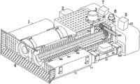
Fig. 1 is a schematic perspective view of the present invention.
Fig. 2 is a perspective sectional view of the present invention.
Fig. 3 is a schematic view of the connection of parts of the components of the present invention.
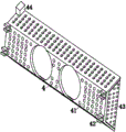
FIG. 4 is a schematic perspective view of an amplification plate according to the present invention.
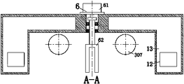
Fig. 5 is a cross-sectional view a-a of fig. 3 of the present invention.
Fig. 6 is a schematic full-section view of a spiral transmission shaft when the pushing body of the invention is a spiral body.
Fig. 7 is a schematic perspective view of a collection holder of the present invention.
Fig. 8 is a perspective view of the fixing bracket of the present invention.
In the figure: the device comprises a buoyancy unit 1, an energy unit 2, a collection unit 3, an amplification plate 4, a controller 5, a direction adjustment unit 6, a Bluetooth emission module 7, a front buoyancy chamber 11, a connecting buoyancy chamber 12, a rear buoyancy chamber 13, a connecting bracket 14, a battery holder 21, a storage battery 22, a collection motor 301, a collection housing 302, a first worm 303, a first gear 304, a second worm 305, a collection bracket 306, a spiral transmission shaft 307, a transmission shaft housing 308, a fixed bracket 309, a second gear 310, a direction adjustment motor 61, a steering plate 62, a bottom plate 41, a connecting installation block 42, a side plate 43, a video collector 44, a connecting body 3061, a connecting body 3062, a front spiral transmission shaft 3071 and a pushing body 3072.
Detailed Description
In order to make the technical means, the creation characteristics, the achievement purposes and the effects of the invention easy to understand, the invention is further described with the specific embodiments.
As shown in fig. 1 to 8, the robot for cleaning water surface of the present invention comprises a buoyancy unit 1, an energy unit 2, a collection unit 3, an amplification plate 4, a controller 5, a direction adjustment unit 6, a bluetooth emission module 7 and a remote controller, wherein the buoyancy unit 1 comprises a front buoyancy compartment 11, a connecting buoyancy compartment 12, a rear buoyancy compartment 13 and a connecting bracket 14, the front buoyancy compartment 11 is connected with the rear buoyancy compartment 13 through the connecting buoyancy compartment 12, and the connecting bracket 14 is arranged on the front buoyancy compartment 11, when the present invention works in a large water area, the present invention can perform amplification combination, so as to improve the working efficiency of the present invention, and the buoyancy unit 1 is mainly used for providing an installation substrate for the present invention; the energy unit 2 is arranged on the connecting buoyancy cabin 12, and the energy unit 2 is mainly used for providing energy supply for the working process of the invention; the collecting unit 3 is positioned in the middle of the buoyancy unit 1, the collecting unit 3 is connected with the buoyancy unit 1, the collecting unit 3 is mainly used for collecting the floaters on the water surface, and meanwhile, the floaters and the water body are driven backwards by utilizing the momentum conservation principle so as to push the water surface floating device to move forwards; the amplification plate 4 is arranged in front of the collection unit 3, and the amplification plate 4 is used for amplifying the contact area of the floating objects, so that the floating objects can be conveniently recovered by the collection unit 3; the controller 5 is positioned above the rear buoyancy cabin 13, the controller 5 is positioned on the left side of the buoyancy unit 1, and the controller 5 is used for controlling the movement of each driving power piece in the invention so as to control the working state of the invention; the direction adjusting unit 6 is arranged in the middle of the rear buoyancy cabin 13, and the direction adjusting unit 6 is used for adjusting the motion state of the invention; the Bluetooth transmitting module 7 is positioned on the right side of the rear buoyancy cabin 13, the Bluetooth transmitting module 7 is connected with the rear buoyancy cabin 13, the Bluetooth transmitting module 7 can transmit working signals of the remote control to the remote controller, and meanwhile, received remote controller signals can be transmitted to the controller 5, so that remote operation of a user on the remote control device is realized; the remote controller works independently of the robot, signal transmission can be carried out between the remote controller and the Bluetooth transmitting module, and the remote controller is used for remotely operating the motion state of the robot.
As shown in fig. 1 to 3, the robot for cleaning water surface according to the present invention includes a battery holder 21 and a battery 22, the battery 22 is connected to the buoyancy chamber 12 through the battery holder 21, and the energy unit 2 is mainly used for providing energy supply for the working process of the present invention.
As shown in fig. 1, 2, 3, 5, 6, 7 and 8, the collection unit 3 of the robot for cleaning water surface of the present invention includes a collection motor 301, a collection housing 302, a first worm 303, a first gear 304, a second worm 305, a collection support 306, a spiral transmission shaft 307, a transmission shaft housing 308, a fixed support 309 and a second gear 310, the collection housing 302 is connected to the buoyancy module 12 through the fixed support 309, drainage holes are uniformly formed on the collection housing 302, the drainage holes are arranged to facilitate the collection unit to recover flotage and convert the momentum of the flotage and water body transmitted backwards into the momentum of the equipment advancing, so as to improve the endurance time of the present invention, and a rotation door is arranged on the bottom surface of the collection housing 2, and when the collection housing 302 is floated and stored to reach a set amount, the rotation door can be opened to pour out the flotage, further, the invention can continue to work; the collecting motor 301 is arranged above the collecting shell 302; the first worm 303 is connected with the collection shell 302 through a bearing; the transmission shaft shell 308 is fixedly connected with the collection shell 302, and the transmission shaft shell 308 is connected with the front buoyancy cabin 11 through a fixing bracket 309; the bottom end of the second worm 305 is connected with the collecting shell 302 through a bearing, the top end of the second worm 305 is connected with the main shaft of the collecting motor 301 through a coupler, and the second worm 305 can rotate under the action of the collecting motor 301; the second gear 310 is arranged in the middle of the first worm 303, the second gear 310 is connected with the second worm 305, and the second worm 305 can rotate under the action of the first worm wheel; the spiral transmission shaft 307 is connected with the collection shell 302 in a double-bearing connection mode, and the double-bearing connection mode is favorable for improving the stability of the spiral transmission shaft 307 and is convenient for realizing the collection work of floaters; the first gear 304 is installed in the middle of the spiral transmission shaft 307, the first gear 304 is meshed with the first worm 303, the spiral transmission shaft 307 can rotate under the action of the first gear 304, when the first gear is in work, the collection motor 301 drives the second worm 305 to rotate so as to drive the second gear 310 on the first worm 303 to rotate, the spiral transmission shaft 307 can rotate under the action of the first gear 304, the spiral transmission shaft 307 can transmit floating objects in the amplification plate 4 to the interior of the collection shell 302, and further the floating object collection function of the invention is realized, as shown in fig. 6, as a preferable technical scheme of the invention, the spiral transmission shaft 307 comprises a front spiral transmission shaft 3071 and a pushing body 3072, the front spiral transmission shaft 3071 is located in the transmission shaft shell 308, the pushing body 3072 is located on the outer side of the collection shell 302, and the front spiral transmission shaft 3071 is connected with the pushing body 3072 through threads, in the process of gradually increasing the floaters in the collecting shell 302, the momentum of the floaters and the water body is not enough to advance the present invention, but the pushing body 3072 can still move in the state of full storage of the floaters, and meanwhile, as a preferred technical scheme of the present invention, the pushing body 3072 can be one of a propeller or a spiral transmission body, and the schematic diagram given for the spiral transmission body is given in fig. 6.
As shown in fig. 5, the direction adjusting unit 6 of the robot for cleaning water surface of the present invention includes a direction adjusting motor 61 and a steering plate 62, the steering plate 62 has a double-layer structure, the double-layer structure is designed to facilitate the effect of the steering plate 62 on the water body, and a direction adjusting shaft is disposed at the top end of the steering plate 62, and the rotation state of the steering plate 62 can be controlled by the direction adjusting shaft, so as to control the steering of the present invention; the direction adjusting motor 61 is connected with the rear buoyancy cabin 13, the direction adjusting motor 61 is connected with the direction adjusting shaft through a coupler, the direction adjusting motor 61 can rotate under the action of the controller 5 to drive the steering plate 62 to rotate, when the collecting unit 3 works, the water body flows backwards, the steering plate 62 is parallel to the water body flowing direction, the water body buoyancy tank is kept straight, if the steering plate 62 forms an included angle with the water body flowing direction, the water body buoyancy tank is in steering movement, and the direction adjusting unit 6 is used for adjusting the moving state of the water body buoyancy tank.
As shown in fig. 4, the robot for cleaning water surface of the present invention, the amplification plate 4 includes a bottom plate 41, a connection mounting block 42, a side plate 43 and a video collector, the side plate 43 is trapezoidal, the side plate 43 is connected with the bottom plate 41 through a revolute pair, the side plate 43 is detachable with respect to the bottom plate 41, the side plate 43 and the bottom plate 41 are both provided with water leakage holes, and the design of the water leakage holes can greatly reduce the resistance of the present invention in the advancing process; the connecting and mounting block 42 is positioned behind the bottom plate 41, and the design of the connecting and mounting block 42 is convenient for realizing the connection between the amplification plates during amplification; the video collector 44 is installed above the bottom plate 41, and the video collector 44 is used for observing the condition of the water surface floating objects, so that the recovery of the water surface floating objects is convenient to realize.
As shown in fig. 7, the robot for cleaning water surface according to the present invention, the collecting bracket 306 includes a connecting body 3061 and an engaging body 3062, the connecting body 3061 and the engaging body 3062 are connected by a bolt, and the engaging body 3062 can also be connected by a bolt, which is convenient for the present invention to select the number of the transmission shaft housings 308 during the production process, so that the present invention can be adapted to the working environment of different areas.
As shown in fig. 8, the robot for cleaning water surface of the present invention has mounting brackets disposed on both left and right sides of the fixing bracket 309, and the mounting brackets are designed to facilitate the expansion of the present invention, so as to improve the working efficiency of the present invention when working in large water areas.
When the robot works, firstly, the connection state of the robot is determined according to the working environment of the robot, if the area of a working water area is large, the robot can be amplified by the connection bracket 14 and the fixing bracket 309, the robots in the robot are combined and connected to improve the working efficiency of the robot in the later floating object cleaning process, after the connection state of the robot is determined, the robot is placed in a working area, all unit components of the robot in the working area work in a matched mode, firstly, the buoyancy unit 1 floats the robot on the water surface, then an operator operates the robot through a remote controller to work, the remote controller transmits a control signal to the Bluetooth transmitting module 7, the Bluetooth transmitting module 7 transmits the signal to the controller 5, then the controller 5 controls the collecting unit 3 to work, the collecting unit 3 transmits the floating objects on the water surface to the collecting shell 302 through spiral transmission, under the action of the collecting unit, the backward movement momentum of the floaters and the water body is converted into the forward movement momentum of the water surface floating device, and the water surface floating device is matched with the work of the direction adjusting unit 6 to finally realize the recovery function of the water surface floaters.
The foregoing illustrates and describes the principles, general features, and advantages of the present invention. It will be understood by those skilled in the art that the present invention is not limited to the embodiments described above, which are given by way of illustration of the principles of the present invention, and that various changes and modifications may be made without departing from the spirit and scope of the invention as defined by the appended claims. The scope of the invention is defined by the appended claims and equivalents thereof.

Claims (10)

1. A robot for cleaning a water surface, characterized by: the device comprises a buoyancy unit (1), an energy unit (2), a collection unit (3), an amplification plate (4), a controller (5), a direction adjustment unit (6), a Bluetooth emission module (7) and a remote controller, wherein the buoyancy unit (1) comprises a front buoyancy cabin (11), a connecting buoyancy cabin (12), a rear buoyancy cabin (13) and a connecting support (14), the front buoyancy cabin (11) is connected with the rear buoyancy cabin (13) through the connecting buoyancy cabin (12), and the connecting support (14) is arranged on the front buoyancy cabin (11); the energy unit (2) is arranged on the connecting buoyancy cabin (12); the collecting unit (3) is positioned in the middle of the buoyancy unit (1), and the collecting unit (3) is connected with the buoyancy unit (1); the amplification plate (4) is arranged in front of the collection unit (3); the controller (5) is positioned above the rear buoyancy cabin (13), and the controller (5) is positioned on the left side of the buoyancy unit (1); the direction adjusting unit (6) is arranged in the middle of the rear buoyancy cabin (13); the Bluetooth transmitting module (7) is positioned on the right side of the rear buoyancy cabin (13), and the Bluetooth transmitting module (7) is connected with the rear buoyancy cabin (13); the remote controller works independently of the robot, and signal transmission can be carried out between the remote controller and the Bluetooth transmitting module;
the energy unit (2) comprises a battery holder (21) and a storage battery (22), and the storage battery (22) is connected with the connecting buoyancy cabin (12) through the battery holder (21);
the collecting unit (3) comprises a collecting motor (301), a collecting shell (302), a first worm (303), a first gear (304), a second worm (305), a collecting support (306), a spiral transmission shaft (307), a transmission shaft shell (308), a fixing support (309) and a second gear (310), the collecting shell (302) is connected with the connecting buoyancy cabin (12) through the fixing support (309), water drainage holes are uniformly formed in the collecting shell (302), and a rotating door is arranged on the bottom surface of the collecting shell; the collecting motor (301) is arranged above the collecting shell (302); the first worm (303) is connected with the collecting shell (302) through a bearing; the transmission shaft shell (308) is fixedly connected with the collection shell (302), and the transmission shaft shell (308) is connected with the front buoyancy cabin (11) through a fixing support (309); the bottom end of the second worm (305) is connected with the collecting shell (302) through a bearing, and the top end of the second worm is connected with a main shaft of a collecting motor (301) through a coupler; the second gear (310) is arranged in the middle of the first worm (303), and the second gear (310) is connected with the second worm (305); the spiral transmission shaft (307) is connected with the collection shell (302) in a double-bearing connection mode; the first gear (304) is arranged in the middle of the spiral transmission shaft (307), and the first gear (304) is meshed with the first worm (303);
the spiral transmission shaft (307) comprises a front spiral transmission shaft (3071) and a pushing body (3072), the front spiral transmission shaft (3071) is positioned inside the transmission shaft shell (308), the pushing body (3072) is positioned outside the collecting shell (302), and the front spiral transmission shaft (3071) is connected with the pushing body (3072) through threads;
the pushing body (3072) can be one of a propeller or a spiral transmission body;
the direction adjusting unit (6) comprises a direction adjusting motor (61) and a steering plate (62), the steering plate (62) is of a double-layer structure, and a direction adjusting shaft is arranged at the top end of the steering plate; the direction adjusting motor (61) is connected with the rear buoyancy cabin (13), and the direction adjusting motor (61) is connected with the direction adjusting shaft through a coupler.
2. A robot for cleaning a water surface, characterized by: the device comprises a buoyancy unit (1), an energy unit (2), a collection unit (3), an amplification plate (4), a controller (5), a direction adjustment unit (6), a Bluetooth emission module (7) and a remote controller, wherein the buoyancy unit (1) comprises a front buoyancy cabin (11), a connecting buoyancy cabin (12), a rear buoyancy cabin (13) and a connecting support (14), the front buoyancy cabin (11) is connected with the rear buoyancy cabin (13) through the connecting buoyancy cabin (12), and the connecting support (14) is arranged on the front buoyancy cabin (11); the energy unit (2) is arranged on the connecting buoyancy cabin (12); the collecting unit (3) is positioned in the middle of the buoyancy unit (1), and the collecting unit (3) is connected with the buoyancy unit (1); the amplification plate (4) is arranged in front of the collection unit (3); the controller (5) is positioned above the rear buoyancy cabin (13), and the controller (5) is positioned on the left side of the buoyancy unit (1); the direction adjusting unit (6) is arranged in the middle of the rear buoyancy cabin (13); the Bluetooth transmitting module (7) is positioned on the right side of the rear buoyancy cabin (13), and the Bluetooth transmitting module (7) is connected with the rear buoyancy cabin (13); the remote controller works independently of the robot, and signal transmission can be carried out between the remote controller and the Bluetooth transmitting module;
the energy unit (2) comprises a battery holder (21) and a storage battery (22), and the storage battery (22) is connected with the connecting buoyancy cabin (12) through the battery holder (21);
the collecting unit (3) comprises a collecting motor (301), a collecting shell (302), a first worm (303), a first gear (304), a second worm (305), a collecting support (306), a spiral transmission shaft (307), a transmission shaft shell (308), a fixing support (309) and a second gear (310), the collecting shell (302) is connected with the connecting buoyancy cabin (12) through the fixing support (309), water drainage holes are uniformly formed in the collecting shell (302), and a rotating door is arranged on the bottom surface of the collecting shell; the collecting motor (301) is arranged above the collecting shell (302); the first worm (303) is connected with the collecting shell (302) through a bearing; the transmission shaft shell (308) is fixedly connected with the collection shell (302), and the transmission shaft shell (308) is connected with the front buoyancy cabin (11) through a fixing support (309); the bottom end of the second worm (305) is connected with the collecting shell (302) through a bearing, and the top end of the second worm is connected with a main shaft of a collecting motor (301) through a coupler; the second gear (310) is arranged in the middle of the first worm (303), and the second gear (310) is connected with the second worm (305); the spiral transmission shaft (307) is connected with the collection shell (302) in a double-bearing connection mode; the first gear (304) is arranged in the middle of the spiral transmission shaft (307), and the first gear (304) is meshed with the first worm (303);
the spiral transmission shaft (307) comprises a front spiral transmission shaft (3071) and a pushing body (3072), the front spiral transmission shaft (3071) is positioned inside the transmission shaft shell (308), the pushing body (3072) is positioned outside the collecting shell (302), and the front spiral transmission shaft (3071) is connected with the pushing body (3072) through threads;
the pushing body (3072) can be one of a propeller or a spiral transmission body;
the amplification plate (4) comprises a bottom plate (41), a connecting and installing block (42), a side plate (43) and a video collector (44), wherein the side plate (43) is trapezoidal, the side plate (43) is connected with the bottom plate (41) through a rotating pair, the side plate (43) is detachable relative to the bottom plate (41), and water leakage holes are formed in the side plate (43) and the bottom plate (41); the connecting and mounting block (42) is positioned behind the bottom plate (41); the video collector (44) is arranged above the bottom plate (41).
3. A robot for cleaning a water surface, characterized by: the device comprises a buoyancy unit (1), an energy unit (2), a collection unit (3), an amplification plate (4), a controller (5), a direction adjustment unit (6), a Bluetooth emission module (7) and a remote controller, wherein the buoyancy unit (1) comprises a front buoyancy cabin (11), a connecting buoyancy cabin (12), a rear buoyancy cabin (13) and a connecting support (14), the front buoyancy cabin (11) is connected with the rear buoyancy cabin (13) through the connecting buoyancy cabin (12), and the connecting support (14) is arranged on the front buoyancy cabin (11); the energy unit (2) is arranged on the connecting buoyancy cabin (12); the collecting unit (3) is positioned in the middle of the buoyancy unit (1), and the collecting unit (3) is connected with the buoyancy unit (1); the amplification plate (4) is arranged in front of the collection unit (3); the controller (5) is positioned above the rear buoyancy cabin (13), and the controller (5) is positioned on the left side of the buoyancy unit (1); the direction adjusting unit (6) is arranged in the middle of the rear buoyancy cabin (13); the Bluetooth transmitting module (7) is positioned on the right side of the rear buoyancy cabin (13), and the Bluetooth transmitting module (7) is connected with the rear buoyancy cabin (13); the remote controller works independently of the robot, and signal transmission can be carried out between the remote controller and the Bluetooth transmitting module;
the energy unit (2) comprises a battery holder (21) and a storage battery (22), and the storage battery (22) is connected with the connecting buoyancy cabin (12) through the battery holder (21);
the collecting unit (3) comprises a collecting motor (301), a collecting shell (302), a first worm (303), a first gear (304), a second worm (305), a collecting support (306), a spiral transmission shaft (307), a transmission shaft shell (308), a fixing support (309) and a second gear (310), the collecting shell (302) is connected with the connecting buoyancy cabin (12) through the fixing support (309), water drainage holes are uniformly formed in the collecting shell (302), and a rotating door is arranged on the bottom surface of the collecting shell; the collecting motor (301) is arranged above the collecting shell (302); the first worm (303) is connected with the collecting shell (302) through a bearing; the transmission shaft shell (308) is fixedly connected with the collection shell (302), and the transmission shaft shell (308) is connected with the front buoyancy cabin (11) through a fixing support (309); the bottom end of the second worm (305) is connected with the collecting shell (302) through a bearing, and the top end of the second worm is connected with a main shaft of a collecting motor (301) through a coupler; the second gear (310) is arranged in the middle of the first worm (303), and the second gear (310) is connected with the second worm (305); the spiral transmission shaft (307) is connected with the collection shell (302) in a double-bearing connection mode; the first gear (304) is arranged in the middle of the spiral transmission shaft (307), and the first gear (304) is meshed with the first worm (303);
the spiral transmission shaft (307) comprises a front spiral transmission shaft (3071) and a pushing body (3072), the front spiral transmission shaft (3071) is positioned inside the transmission shaft shell (308), the pushing body (3072) is positioned outside the collecting shell (302), and the front spiral transmission shaft (3071) is connected with the pushing body (3072) through threads;
the pushing body (3072) can be one of a propeller or a spiral transmission body;
the collecting support (306) comprises a connecting body (3061) and a connecting body (3062), the connecting body (3061) and the connecting body (3062) are connected through a bolt, and the connecting body (3062) can also be connected through a bolt.
4. A robot for cleaning a water surface, characterized by: the device comprises a buoyancy unit (1), an energy unit (2), a collection unit (3), an amplification plate (4), a controller (5), a direction adjustment unit (6), a Bluetooth emission module (7) and a remote controller, wherein the buoyancy unit (1) comprises a front buoyancy cabin (11), a connecting buoyancy cabin (12), a rear buoyancy cabin (13) and a connecting support (14), the front buoyancy cabin (11) is connected with the rear buoyancy cabin (13) through the connecting buoyancy cabin (12), and the connecting support (14) is arranged on the front buoyancy cabin (11); the energy unit (2) is arranged on the connecting buoyancy cabin (12); the collecting unit (3) is positioned in the middle of the buoyancy unit (1), and the collecting unit (3) is connected with the buoyancy unit (1); the amplification plate (4) is arranged in front of the collection unit (3); the controller (5) is positioned above the rear buoyancy cabin (13), and the controller (5) is positioned on the left side of the buoyancy unit (1); the direction adjusting unit (6) is arranged in the middle of the rear buoyancy cabin (13); the Bluetooth transmitting module (7) is positioned on the right side of the rear buoyancy cabin (13), and the Bluetooth transmitting module (7) is connected with the rear buoyancy cabin (13); the remote controller works independently of the robot, and signal transmission can be carried out between the remote controller and the Bluetooth transmitting module;
the energy unit (2) comprises a battery holder (21) and a storage battery (22), and the storage battery (22) is connected with the connecting buoyancy cabin (12) through the battery holder (21);
the collecting unit (3) comprises a collecting motor (301), a collecting shell (302), a first worm (303), a first gear (304), a second worm (305), a collecting support (306), a spiral transmission shaft (307), a transmission shaft shell (308), a fixing support (309) and a second gear (310), the collecting shell (302) is connected with the connecting buoyancy cabin (12) through the fixing support (309), water drainage holes are uniformly formed in the collecting shell (302), and a rotating door is arranged on the bottom surface of the collecting shell; the collecting motor (301) is arranged above the collecting shell (302); the first worm (303) is connected with the collecting shell (302) through a bearing; the transmission shaft shell (308) is fixedly connected with the collection shell (302), and the transmission shaft shell (308) is connected with the front buoyancy cabin (11) through a fixing support (309); the bottom end of the second worm (305) is connected with the collecting shell (302) through a bearing, and the top end of the second worm is connected with a main shaft of a collecting motor (301) through a coupler; the second gear (310) is arranged in the middle of the first worm (303), and the second gear (310) is connected with the second worm (305); the spiral transmission shaft (307) is connected with the collection shell (302) in a double-bearing connection mode; the first gear (304) is arranged in the middle of the spiral transmission shaft (307), and the first gear (304) is meshed with the first worm (303);
the spiral transmission shaft (307) comprises a front spiral transmission shaft (3071) and a pushing body (3072), the front spiral transmission shaft (3071) is positioned inside the transmission shaft shell (308), the pushing body (3072) is positioned outside the collecting shell (302), and the front spiral transmission shaft (3071) is connected with the pushing body (3072) through threads;
the pushing body (3072) can be one of a propeller or a spiral transmission body;
the left side and the right side of the fixed support (309) are provided with mounting supports.
5. A robot for cleaning a water surface, characterized by: the device comprises a buoyancy unit (1), an energy unit (2), a collection unit (3), an amplification plate (4), a controller (5), a direction adjustment unit (6), a Bluetooth emission module (7) and a remote controller, wherein the buoyancy unit (1) comprises a front buoyancy cabin (11), a connecting buoyancy cabin (12), a rear buoyancy cabin (13) and a connecting support (14), the front buoyancy cabin (11) is connected with the rear buoyancy cabin (13) through the connecting buoyancy cabin (12), and the connecting support (14) is arranged on the front buoyancy cabin (11); the energy unit (2) is arranged on the connecting buoyancy cabin (12); the collecting unit (3) is positioned in the middle of the buoyancy unit (1), and the collecting unit (3) is connected with the buoyancy unit (1); the amplification plate (4) is arranged in front of the collection unit (3); the controller (5) is positioned above the rear buoyancy cabin (13), and the controller (5) is positioned on the left side of the buoyancy unit (1); the direction adjusting unit (6) is arranged in the middle of the rear buoyancy cabin (13); the Bluetooth transmitting module (7) is positioned on the right side of the rear buoyancy cabin (13), and the Bluetooth transmitting module (7) is connected with the rear buoyancy cabin (13); the remote controller works independently of the robot, and signal transmission can be carried out between the remote controller and the Bluetooth transmitting module;
the energy unit (2) comprises a battery holder (21) and a storage battery (22), and the storage battery (22) is connected with the connecting buoyancy cabin (12) through the battery holder (21);
the collecting unit (3) comprises a collecting motor (301), a collecting shell (302), a first worm (303), a first gear (304), a second worm (305), a collecting support (306), a spiral transmission shaft (307), a transmission shaft shell (308), a fixing support (309) and a second gear (310), the collecting shell (302) is connected with the connecting buoyancy cabin (12) through the fixing support (309), water drainage holes are uniformly formed in the collecting shell (302), and a rotating door is arranged on the bottom surface of the collecting shell; the collecting motor (301) is arranged above the collecting shell (302); the first worm (303) is connected with the collecting shell (302) through a bearing; the transmission shaft shell (308) is fixedly connected with the collection shell (302), and the transmission shaft shell (308) is connected with the front buoyancy cabin (11) through a fixing support (309); the bottom end of the second worm (305) is connected with the collecting shell (302) through a bearing, and the top end of the second worm is connected with a main shaft of a collecting motor (301) through a coupler; the second gear (310) is arranged in the middle of the first worm (303), and the second gear (310) is connected with the second worm (305); the spiral transmission shaft (307) is connected with the collection shell (302) in a double-bearing connection mode; the first gear (304) is arranged in the middle of the spiral transmission shaft (307), and the first gear (304) is meshed with the first worm (303);
the direction adjusting unit (6) comprises a direction adjusting motor (61) and a steering plate (62), the steering plate (62) is of a double-layer structure, and a direction adjusting shaft is arranged at the top end of the steering plate; the direction adjusting motor (61) is connected with the rear buoyancy cabin (13), and the direction adjusting motor (61) is connected with the direction adjusting shaft through a coupler;
the amplification plate (4) comprises a bottom plate (41), a connecting and installing block (42), a side plate (43) and a video collector (44), wherein the side plate (43) is trapezoidal, the side plate (43) is connected with the bottom plate (41) through a rotating pair, the side plate (43) is detachable relative to the bottom plate (41), and water leakage holes are formed in the side plate (43) and the bottom plate (41); the connecting and mounting block (42) is positioned behind the bottom plate (41); the video collector (44) is arranged above the bottom plate (41).
6. A robot for cleaning a water surface, characterized by: the device comprises a buoyancy unit (1), an energy unit (2), a collection unit (3), an amplification plate (4), a controller (5), a direction adjustment unit (6), a Bluetooth emission module (7) and a remote controller, wherein the buoyancy unit (1) comprises a front buoyancy cabin (11), a connecting buoyancy cabin (12), a rear buoyancy cabin (13) and a connecting support (14), the front buoyancy cabin (11) is connected with the rear buoyancy cabin (13) through the connecting buoyancy cabin (12), and the connecting support (14) is arranged on the front buoyancy cabin (11); the energy unit (2) is arranged on the connecting buoyancy cabin (12); the collecting unit (3) is positioned in the middle of the buoyancy unit (1), and the collecting unit (3) is connected with the buoyancy unit (1); the amplification plate (4) is arranged in front of the collection unit (3); the controller (5) is positioned above the rear buoyancy cabin (13), and the controller (5) is positioned on the left side of the buoyancy unit (1); the direction adjusting unit (6) is arranged in the middle of the rear buoyancy cabin (13); the Bluetooth transmitting module (7) is positioned on the right side of the rear buoyancy cabin (13), and the Bluetooth transmitting module (7) is connected with the rear buoyancy cabin (13); the remote controller works independently of the robot, and signal transmission can be carried out between the remote controller and the Bluetooth transmitting module;
the energy unit (2) comprises a battery holder (21) and a storage battery (22), and the storage battery (22) is connected with the connecting buoyancy cabin (12) through the battery holder (21);
the collecting unit (3) comprises a collecting motor (301), a collecting shell (302), a first worm (303), a first gear (304), a second worm (305), a collecting support (306), a spiral transmission shaft (307), a transmission shaft shell (308), a fixing support (309) and a second gear (310), the collecting shell (302) is connected with the connecting buoyancy cabin (12) through the fixing support (309), water drainage holes are uniformly formed in the collecting shell (302), and a rotating door is arranged on the bottom surface of the collecting shell; the collecting motor (301) is arranged above the collecting shell (302); the first worm (303) is connected with the collecting shell (302) through a bearing; the transmission shaft shell (308) is fixedly connected with the collection shell (302), and the transmission shaft shell (308) is connected with the front buoyancy cabin (11) through a fixing support (309); the bottom end of the second worm (305) is connected with the collecting shell (302) through a bearing, and the top end of the second worm is connected with a main shaft of a collecting motor (301) through a coupler; the second gear (310) is arranged in the middle of the first worm (303), and the second gear (310) is connected with the second worm (305); the spiral transmission shaft (307) is connected with the collection shell (302) in a double-bearing connection mode; the first gear (304) is arranged in the middle of the spiral transmission shaft (307), and the first gear (304) is meshed with the first worm (303);
the direction adjusting unit (6) comprises a direction adjusting motor (61) and a steering plate (62), the steering plate (62) is of a double-layer structure, and a direction adjusting shaft is arranged at the top end of the steering plate; the direction adjusting motor (61) is connected with the rear buoyancy cabin (13), and the direction adjusting motor (61) is connected with the direction adjusting shaft through a coupler;
the collecting support (306) comprises a connecting body (3061) and a connecting body (3062), the connecting body (3061) and the connecting body (3062) are connected through a bolt, and the connecting body (3062) can also be connected through a bolt.
7. A robot for cleaning a water surface, characterized by: the device comprises a buoyancy unit (1), an energy unit (2), a collection unit (3), an amplification plate (4), a controller (5), a direction adjustment unit (6), a Bluetooth emission module (7) and a remote controller, wherein the buoyancy unit (1) comprises a front buoyancy cabin (11), a connecting buoyancy cabin (12), a rear buoyancy cabin (13) and a connecting support (14), the front buoyancy cabin (11) is connected with the rear buoyancy cabin (13) through the connecting buoyancy cabin (12), and the connecting support (14) is arranged on the front buoyancy cabin (11); the energy unit (2) is arranged on the connecting buoyancy cabin (12); the collecting unit (3) is positioned in the middle of the buoyancy unit (1), and the collecting unit (3) is connected with the buoyancy unit (1); the amplification plate (4) is arranged in front of the collection unit (3); the controller (5) is positioned above the rear buoyancy cabin (13), and the controller (5) is positioned on the left side of the buoyancy unit (1); the direction adjusting unit (6) is arranged in the middle of the rear buoyancy cabin (13); the Bluetooth transmitting module (7) is positioned on the right side of the rear buoyancy cabin (13), and the Bluetooth transmitting module (7) is connected with the rear buoyancy cabin (13); the remote controller works independently of the robot, and signal transmission can be carried out between the remote controller and the Bluetooth transmitting module;
the energy unit (2) comprises a battery holder (21) and a storage battery (22), and the storage battery (22) is connected with the connecting buoyancy cabin (12) through the battery holder (21);
the collecting unit (3) comprises a collecting motor (301), a collecting shell (302), a first worm (303), a first gear (304), a second worm (305), a collecting support (306), a spiral transmission shaft (307), a transmission shaft shell (308), a fixing support (309) and a second gear (310), the collecting shell (302) is connected with the connecting buoyancy cabin (12) through the fixing support (309), water drainage holes are uniformly formed in the collecting shell (302), and a rotating door is arranged on the bottom surface of the collecting shell; the collecting motor (301) is arranged above the collecting shell (302); the first worm (303) is connected with the collecting shell (302) through a bearing; the transmission shaft shell (308) is fixedly connected with the collection shell (302), and the transmission shaft shell (308) is connected with the front buoyancy cabin (11) through a fixing support (309); the bottom end of the second worm (305) is connected with the collecting shell (302) through a bearing, and the top end of the second worm is connected with a main shaft of a collecting motor (301) through a coupler; the second gear (310) is arranged in the middle of the first worm (303), and the second gear (310) is connected with the second worm (305); the spiral transmission shaft (307) is connected with the collection shell (302) in a double-bearing connection mode; the first gear (304) is arranged in the middle of the spiral transmission shaft (307), and the first gear (304) is meshed with the first worm (303);
the direction adjusting unit (6) comprises a direction adjusting motor (61) and a steering plate (62), the steering plate (62) is of a double-layer structure, and a direction adjusting shaft is arranged at the top end of the steering plate; the direction adjusting motor (61) is connected with the rear buoyancy cabin (13), and the direction adjusting motor (61) is connected with the direction adjusting shaft through a coupler;
the left side and the right side of the fixed support (309) are provided with mounting supports.
8. A robot for cleaning a water surface, characterized by: the device comprises a buoyancy unit (1), an energy unit (2), a collection unit (3), an amplification plate (4), a controller (5), a direction adjustment unit (6), a Bluetooth emission module (7) and a remote controller, wherein the buoyancy unit (1) comprises a front buoyancy cabin (11), a connecting buoyancy cabin (12), a rear buoyancy cabin (13) and a connecting support (14), the front buoyancy cabin (11) is connected with the rear buoyancy cabin (13) through the connecting buoyancy cabin (12), and the connecting support (14) is arranged on the front buoyancy cabin (11); the energy unit (2) is arranged on the connecting buoyancy cabin (12); the collecting unit (3) is positioned in the middle of the buoyancy unit (1), and the collecting unit (3) is connected with the buoyancy unit (1); the amplification plate (4) is arranged in front of the collection unit (3); the controller (5) is positioned above the rear buoyancy cabin (13), and the controller (5) is positioned on the left side of the buoyancy unit (1); the direction adjusting unit (6) is arranged in the middle of the rear buoyancy cabin (13); the Bluetooth transmitting module (7) is positioned on the right side of the rear buoyancy cabin (13), and the Bluetooth transmitting module (7) is connected with the rear buoyancy cabin (13); the remote controller works independently of the robot, and signal transmission can be carried out between the remote controller and the Bluetooth transmitting module;
the energy unit (2) comprises a battery holder (21) and a storage battery (22), and the storage battery (22) is connected with the connecting buoyancy cabin (12) through the battery holder (21);
the collecting unit (3) comprises a collecting motor (301), a collecting shell (302), a first worm (303), a first gear (304), a second worm (305), a collecting support (306), a spiral transmission shaft (307), a transmission shaft shell (308), a fixing support (309) and a second gear (310), the collecting shell (302) is connected with the connecting buoyancy cabin (12) through the fixing support (309), water drainage holes are uniformly formed in the collecting shell (302), and a rotating door is arranged on the bottom surface of the collecting shell; the collecting motor (301) is arranged above the collecting shell (302); the first worm (303) is connected with the collecting shell (302) through a bearing; the transmission shaft shell (308) is fixedly connected with the collection shell (302), and the transmission shaft shell (308) is connected with the front buoyancy cabin (11) through a fixing support (309); the bottom end of the second worm (305) is connected with the collecting shell (302) through a bearing, and the top end of the second worm is connected with a main shaft of a collecting motor (301) through a coupler; the second gear (310) is arranged in the middle of the first worm (303), and the second gear (310) is connected with the second worm (305); the spiral transmission shaft (307) is connected with the collection shell (302) in a double-bearing connection mode; the first gear (304) is arranged in the middle of the spiral transmission shaft (307), and the first gear (304) is meshed with the first worm (303);
the amplification plate (4) comprises a bottom plate (41), a connecting and installing block (42), a side plate (43) and a video collector (44), wherein the side plate (43) is trapezoidal, the side plate (43) is connected with the bottom plate (41) through a rotating pair, the side plate (43) is detachable relative to the bottom plate (41), and water leakage holes are formed in the side plate (43) and the bottom plate (41); the connecting and mounting block (42) is positioned behind the bottom plate (41); the video collector (44) is arranged above the bottom plate (41);
the collecting support (306) comprises a connecting body (3061) and a connecting body (3062), the connecting body (3061) and the connecting body (3062) are connected through a bolt, and the connecting body (3062) can also be connected through a bolt.
9. A robot for cleaning a water surface, characterized by: the device comprises a buoyancy unit (1), an energy unit (2), a collection unit (3), an amplification plate (4), a controller (5), a direction adjustment unit (6), a Bluetooth emission module (7) and a remote controller, wherein the buoyancy unit (1) comprises a front buoyancy cabin (11), a connecting buoyancy cabin (12), a rear buoyancy cabin (13) and a connecting support (14), the front buoyancy cabin (11) is connected with the rear buoyancy cabin (13) through the connecting buoyancy cabin (12), and the connecting support (14) is arranged on the front buoyancy cabin (11); the energy unit (2) is arranged on the connecting buoyancy cabin (12); the collecting unit (3) is positioned in the middle of the buoyancy unit (1), and the collecting unit (3) is connected with the buoyancy unit (1); the amplification plate (4) is arranged in front of the collection unit (3); the controller (5) is positioned above the rear buoyancy cabin (13), and the controller (5) is positioned on the left side of the buoyancy unit (1); the direction adjusting unit (6) is arranged in the middle of the rear buoyancy cabin (13); the Bluetooth transmitting module (7) is positioned on the right side of the rear buoyancy cabin (13), and the Bluetooth transmitting module (7) is connected with the rear buoyancy cabin (13); the remote controller works independently of the robot, and signal transmission can be carried out between the remote controller and the Bluetooth transmitting module;
the energy unit (2) comprises a battery holder (21) and a storage battery (22), and the storage battery (22) is connected with the connecting buoyancy cabin (12) through the battery holder (21);
the collecting unit (3) comprises a collecting motor (301), a collecting shell (302), a first worm (303), a first gear (304), a second worm (305), a collecting support (306), a spiral transmission shaft (307), a transmission shaft shell (308), a fixing support (309) and a second gear (310), the collecting shell (302) is connected with the connecting buoyancy cabin (12) through the fixing support (309), water drainage holes are uniformly formed in the collecting shell (302), and a rotating door is arranged on the bottom surface of the collecting shell; the collecting motor (301) is arranged above the collecting shell (302); the first worm (303) is connected with the collecting shell (302) through a bearing; the transmission shaft shell (308) is fixedly connected with the collection shell (302), and the transmission shaft shell (308) is connected with the front buoyancy cabin (11) through a fixing support (309); the bottom end of the second worm (305) is connected with the collecting shell (302) through a bearing, and the top end of the second worm is connected with a main shaft of a collecting motor (301) through a coupler; the second gear (310) is arranged in the middle of the first worm (303), and the second gear (310) is connected with the second worm (305); the spiral transmission shaft (307) is connected with the collection shell (302) in a double-bearing connection mode; the first gear (304) is arranged in the middle of the spiral transmission shaft (307), and the first gear (304) is meshed with the first worm (303);
the amplification plate (4) comprises a bottom plate (41), a connecting and installing block (42), a side plate (43) and a video collector (44), wherein the side plate (43) is trapezoidal, the side plate (43) is connected with the bottom plate (41) through a rotating pair, the side plate (43) is detachable relative to the bottom plate (41), and water leakage holes are formed in the side plate (43) and the bottom plate (41); the connecting and mounting block (42) is positioned behind the bottom plate (41); the video collector (44) is arranged above the bottom plate (41);
the left side and the right side of the fixed support (309) are provided with mounting supports.
10. A robot for cleaning a water surface, characterized by: the device comprises a buoyancy unit (1), an energy unit (2), a collection unit (3), an amplification plate (4), a controller (5), a direction adjustment unit (6), a Bluetooth emission module (7) and a remote controller, wherein the buoyancy unit (1) comprises a front buoyancy cabin (11), a connecting buoyancy cabin (12), a rear buoyancy cabin (13) and a connecting support (14), the front buoyancy cabin (11) is connected with the rear buoyancy cabin (13) through the connecting buoyancy cabin (12), and the connecting support (14) is arranged on the front buoyancy cabin (11); the energy unit (2) is arranged on the connecting buoyancy cabin (12); the collecting unit (3) is positioned in the middle of the buoyancy unit (1), and the collecting unit (3) is connected with the buoyancy unit (1); the amplification plate (4) is arranged in front of the collection unit (3); the controller (5) is positioned above the rear buoyancy cabin (13), and the controller (5) is positioned on the left side of the buoyancy unit (1); the direction adjusting unit (6) is arranged in the middle of the rear buoyancy cabin (13); the Bluetooth transmitting module (7) is positioned on the right side of the rear buoyancy cabin (13), and the Bluetooth transmitting module (7) is connected with the rear buoyancy cabin (13); the remote controller works independently of the robot, and signal transmission can be carried out between the remote controller and the Bluetooth transmitting module;
the energy unit (2) comprises a battery holder (21) and a storage battery (22), and the storage battery (22) is connected with the connecting buoyancy cabin (12) through the battery holder (21);
the collecting unit (3) comprises a collecting motor (301), a collecting shell (302), a first worm (303), a first gear (304), a second worm (305), a collecting support (306), a spiral transmission shaft (307), a transmission shaft shell (308), a fixing support (309) and a second gear (310), the collecting shell (302) is connected with the connecting buoyancy cabin (12) through the fixing support (309), water drainage holes are uniformly formed in the collecting shell (302), and a rotating door is arranged on the bottom surface of the collecting shell; the collecting motor (301) is arranged above the collecting shell (302); the first worm (303) is connected with the collecting shell (302) through a bearing; the transmission shaft shell (308) is fixedly connected with the collection shell (302), and the transmission shaft shell (308) is connected with the front buoyancy cabin (11) through a fixing support (309); the bottom end of the second worm (305) is connected with the collecting shell (302) through a bearing, and the top end of the second worm is connected with a main shaft of a collecting motor (301) through a coupler; the second gear (310) is arranged in the middle of the first worm (303), and the second gear (310) is connected with the second worm (305); the spiral transmission shaft (307) is connected with the collection shell (302) in a double-bearing connection mode; the first gear (304) is arranged in the middle of the spiral transmission shaft (307), and the first gear (304) is meshed with the first worm (303);
the collecting bracket (306) comprises a connecting body (3061) and an adapter body (3062), the connecting body (3061) and the adapter body (3062) are connected through a bolt, and the adapter body (3062) can also be connected through a bolt;
the left side and the right side of the fixed support (309) are provided with mounting supports.
CN201810852065.7A 2017-03-06 2017-03-06 Robot for cleaning water surface Active CN108839766B (en)

Priority Applications (1)

Application Number Priority Date Filing Date Title
CN201810852065.7A CN108839766B (en) 2017-03-06 2017-03-06 Robot for cleaning water surface

Applications Claiming Priority (2)

Application Number Priority Date Filing Date Title
CN201710128263.4A CN106926985B (en) 2017-03-06 2017-03-06 A kind of robot for water surface cleaner
CN201810852065.7A CN108839766B (en) 2017-03-06 2017-03-06 Robot for cleaning water surface

Related Parent Applications (1)

Application Number Title Priority Date Filing Date
CN201710128263.4A Division CN106926985B (en) 2017-03-06 2017-03-06 A kind of robot for water surface cleaner

Publications (2)

Publication Number Publication Date
CN108839766A CN108839766A (en) 2018-11-20
CN108839766B true CN108839766B (en) 2020-08-28

Family

ID=59424441

Family Applications (3)

Application Number Title Priority Date Filing Date
CN201810852063.8A Active CN108839765B (en) 2017-03-06 2017-03-06 Robot for cleaning water surface
CN201810852065.7A Active CN108839766B (en) 2017-03-06 2017-03-06 Robot for cleaning water surface
CN201710128263.4A Active CN106926985B (en) 2017-03-06 2017-03-06 A kind of robot for water surface cleaner

Family Applications Before (1)

Application Number Title Priority Date Filing Date
CN201810852063.8A Active CN108839765B (en) 2017-03-06 2017-03-06 Robot for cleaning water surface

Family Applications After (1)

Application Number Title Priority Date Filing Date
CN201710128263.4A Active CN106926985B (en) 2017-03-06 2017-03-06 A kind of robot for water surface cleaner

Country Status (1)

Country Link
CN (3) CN108839765B (en)

Families Citing this family (4)

* Cited by examiner, † Cited by third party
Publication number Priority date Publication date Assignee Title
CN108839765B (en) * 2017-03-06 2020-08-28 浙江雷奥重工机械有限公司 Robot for cleaning water surface
CN108018838B (en) * 2017-12-12 2019-11-12 曹诗晴 A kind of environmental protection humanoid robot
CN111608155B (en) * 2018-05-23 2021-12-21 温州耐特尔自动化设备有限公司 Dam surface of water waste collection device
CN113653020B (en) * 2021-08-26 2022-12-16 中国人民解放军国防科技大学 Full-water-layer intelligent cleaning robot and cleaning method

Family Cites Families (11)

* Cited by examiner, † Cited by third party
Publication number Priority date Publication date Assignee Title
DE202004019997U1 (en) * 2004-12-21 2005-02-24 Erhartitsch, Karl Swimming tub e.g. for collecting mineral oil from water surface after tanker accidents, has high ranking flap and floats with hydraulic cylinder pressed downwards
CN101475047A (en) * 2008-10-16 2009-07-08 桂林电子科技大学 Small-sized water surface floater automatic cleaning ship
CN203211483U (en) * 2013-04-18 2013-09-25 上海电机学院 Small remote-control catamaran for salvaging floats
CN103640676B (en) * 2013-11-13 2016-08-17 梧州学院 Remote control intelligent rubbish salvage ship
CN104386213B (en) * 2014-10-20 2017-08-08 上海电机学院 Remote Control Automatic pick-up boat
CN204606156U (en) * 2015-05-16 2015-09-02 武汉科技大学 The automatic salvor of a kind of garbage on water
CN205366002U (en) * 2016-01-26 2016-07-06 高莉 Equipment that water surface garbage handled
CN105936331B (en) * 2016-05-24 2017-11-21 骆伟民 A kind of special moving device of marine pollution floating object clean robot
CN106347594B (en) * 2016-10-21 2018-02-09 杭州电子科技大学 A kind of wireless charging clears up water surface robot system automatically
CN106428444B (en) * 2016-12-08 2018-06-29 扬州工业职业技术学院 A kind of small-size water surface decontaminates ship
CN108839765B (en) * 2017-03-06 2020-08-28 浙江雷奥重工机械有限公司 Robot for cleaning water surface

Also Published As

Publication number Publication date
CN106926985A (en) 2017-07-07
CN108839765A (en) 2018-11-20
CN108839765B (en) 2020-08-28
CN108839766A (en) 2018-11-20
CN106926985B (en) 2018-09-14

Similar Documents

Publication Publication Date Title
CN108839766B (en) Robot for cleaning water surface
CN203078725U (en) Lake surface cleaning ship
CN212956473U (en) Be applied to ecological prosthetic devices that black and odorous water body administered
CN200959731Y (en) Mower
CN110397009B (en) Automatic robot for removing blue algae
CN215844696U (en) Pipeline robot capable of automatically cleaning dirt
CN213323590U (en) Unmanned ship for cleaning floating objects on water surface of urban inland river
CN212667613U (en) Water surface garbage cleaning robot for small and medium water areas
CN212556706U (en) Solar water surface garbage cleaning robot
CN213741265U (en) Energy-concerving and environment-protective type excavator with solar energy auxiliary power supply
CN216303423U (en) Ecological restoration energy-saving and environment-friendly device for polluted river water body
CN108100177B (en) Intelligent remote control garbage negative pressure ship
CN210327492U (en) Solar panel snow removing device
CN206971190U (en) A kind of refuse sweeping machine people waterborne
CN211646314U (en) Remote control ship for recycling water surface garbage
CN212976187U (en) Wireless pipeline cleaning robot
CN114438984A (en) Water surface floating garbage collecting device
CN109169143B (en) Excavation device for nursery stock transplantation
CN109606597B (en) Remote control type jet pump propeller
CN115362945B (en) Sheep hurdle trench cleaning robot
CN217386623U (en) Culture propagation display fence with ash removal function
CN215474284U (en) Amphibious spiral driving multifunctional operation platform based on unmanned/manned control
CN220241474U (en) Omnidirectional garbage pickup robot for pipeline
CN216454841U (en) Cleaning robot capable of automatically adjusting cleaning force
CN213351748U (en) Superhard materials machine tool

Legal Events

Date Code Title Description
PB01 Publication
PB01 Publication
SE01 Entry into force of request for substantive examination
TA01 Transfer of patent application right

Effective date of registration: 20200730

Address after: 325000 building a, No.1 building, plot c607, Binhai san dao 15 road, Wenzhou Economic and Technological Development Zone, Wenzhou City, Zhejiang Province

Applicant after: ZHEJIANG LEIAO HEAVY INDUSTRY MACHINERY Co.,Ltd.

Address before: 110508 Group 880, Taodaiton Village, Dongguantun Town, Pingxian County, Shenyang City, Liaoning Province

Applicant before: Wang Guotao

TA01 Transfer of patent application right
GR01 Patent grant
GR01 Patent grant
TR01 Transfer of patent right

Effective date of registration: 20211228

Address after: 211600 No. 28, Jianshe West Road, Minqiao industrial concentration zone, Jinhu County, Huai'an City, Jiangsu Province

Patentee after: Jiangsu Houde Instrument Co.,Ltd.

Address before: 325000 building a, No. 1, plot c607, Binhai Sandao 15th Road, Wenzhou Economic and Technological Development Zone, Wenzhou City, Zhejiang Province

Patentee before: ZHEJIANG LEIAO HEAVY INDUSTRY MACHINERY CO.,LTD.

TR01 Transfer of patent right