CN108815967B - Environment-friendly chemical equipment waste gas treatment device and operation method thereof - Google Patents
Environment-friendly chemical equipment waste gas treatment device and operation method thereof Download PDFInfo
- Publication number
- CN108815967B CN108815967B CN201810732026.3A CN201810732026A CN108815967B CN 108815967 B CN108815967 B CN 108815967B CN 201810732026 A CN201810732026 A CN 201810732026A CN 108815967 B CN108815967 B CN 108815967B
- Authority
- CN
- China
- Prior art keywords
- smoke
- flue gas
- dust
- waste gas
- frame
- Prior art date
- Legal status (The legal status is an assumption and is not a legal conclusion. Google has not performed a legal analysis and makes no representation as to the accuracy of the status listed.)
- Active
Links
Images


Classifications
-
- B—PERFORMING OPERATIONS; TRANSPORTING
- B01—PHYSICAL OR CHEMICAL PROCESSES OR APPARATUS IN GENERAL
- B01D—SEPARATION
- B01D50/00—Combinations of methods or devices for separating particles from gases or vapours
- B01D50/60—Combinations of devices covered by groups B01D46/00 and B01D47/00
-
- G—PHYSICS
- G01—MEASURING; TESTING
- G01N—INVESTIGATING OR ANALYSING MATERIALS BY DETERMINING THEIR CHEMICAL OR PHYSICAL PROPERTIES
- G01N15/00—Investigating characteristics of particles; Investigating permeability, pore-volume, or surface-area of porous materials
Abstract
The invention provides an environment-friendly chemical equipment waste gas treatment device which comprises a bottom plate, a flue gas collecting guide pipe structure, a flue gas dust removal box structure, a U-shaped smoke guide pipe, a primary smoke filter box structure, a gas guide pipe, a longitudinal support, an installation frame, a touch screen, a controller, a power switch, a smoke guide frame, a secondary filtering and purifying frame structure, a flue gas residue detection rod structure and a smoke outlet pipe, wherein the flue gas collecting guide pipe structure is arranged at the upper part of the left side of the flue gas dust removal box structure; the flue gas dust removal box structure is arranged on the left side of the upper part of the bottom plate; the primary smoke filtering box structure is arranged on the right side of the smoke dust removing box structure and is arranged on the upper portion of the bottom plate. The invention is convenient to detect the residual amount of dust in the filtered smoke, has good secondary filtering rate effect on the smoke and can filter larger impurities during air extraction; meanwhile, the using method is simple and easy to operate, pollution-free and capable of carrying out large-scale treatment and purification work.
Description
Technical Field
The invention belongs to the technical field of purification and treatment of atmospheric dust pollution in an open-pit mining area and fire extinguishing and greening of the mining area, and particularly relates to an environment-friendly chemical equipment waste gas treatment device and an operation method thereof.
Background
The colorless and odorless dioxin is the poison of century, which is generated from exhaust gas caused by combustion, and is existed in animals or vegetables and fruits, and then enters human body through food chain to be absorbed by human body, so that many diseases such as liver, immune system, muscle and joint pain, abortion, teratocarcinoma, visual impairment and the like are caused, and the handling of dioxin is one of the most spotlighted problems at present. In general, an alkaline absorbent tower is used to remove acid gases and dioxin toxic gases from exhaust gas generated from an incinerator or other combustion system, activated carbon is used to adsorb dioxin, and a bag filter (bag filter) is used to remove particulates and activated carbon adsorbed pollutants.
Prior art patent application number 201510434310.9 discloses an organic waste gas's preprocessing device and application method, and preprocessing device includes cooling deodorizing tower and tertiary clean room, cooling deodorizing tower includes one-level cooling room and second grade deodorizing room, the one-level cooling room includes hot gas inlet, a plurality of layers of spray room and moisture export, second grade deodorizing room from the top down includes odorless gas export, deodorizing room shower head, packing layer, water collecting box and moisture import in proper order, tertiary clean room includes a plurality of cyclone, cyclone includes casing, odorless gas import, lower part hopper and dustless gas outlet.
Prior art patent application No. 201711212636.2 discloses a chemical industry reation kettle with exhaust treatment device, including reation kettle, reation kettle's bottom erection bracing seat, the bottom installation motor of supporting seat, the output shaft installation (mixing) shaft of motor, the outer wall of (mixing) shaft is from up installing hemisphere stirring head, first stirring leaf, rhombus stirring leaf and second stirring leaf down in proper order, reation kettle's top central authorities install feed hopper, feed hopper top installation proportioning device, the exhaust hole has been seted up on reation kettle top right side, the exhaust hole passes through the blast pipe and connects the rose box, the cover is collected in the right side installation of rose box, collect the cover and pass through pipe connection purifying box, the proportioning device at reation kettle top.
Prior art patent application number CN201710591878.0 discloses an utilize combustor of exhaust-gas treatment waste liquid, offer the dustcoat of air vent including the top, and be located shower nozzle in the dustcoat, the dustcoat top with be equipped with the ignition with the dustcoat rigid coupling in the combustion chamber between the shower nozzle, seted up on the shower nozzle with the atomization hole of combustion chamber intercommunication, the atomization hole communicates with the waste water pipe who installs the force (forcing) pump, form the combustible gas passageway between waste water pipe and the dustcoat lateral wall, the combustible gas passageway passes through a plurality of burning holes of seting up on the shower nozzle with combustion chamber intercommunication.
However, the existing waste gas treatment device for the environment-friendly chemical equipment and the operation method thereof have the problems that the residual dust amount of the filtered flue gas is not provided, the filtering effect on larger impurities is not provided when non-waste gas is extracted, and the secondary purification on the flue gas is not provided.
Therefore, it is very necessary to invent an environment-friendly chemical equipment waste gas treatment device and an operation method thereof.
Disclosure of Invention
In order to solve the technical problems, the invention provides an environment-friendly chemical equipment waste gas treatment device and an operation method thereof, the waste gas treatment device comprises a bottom plate, a flue gas collecting guide pipe structure, a flue gas dust removal box structure, a U-shaped smoke guide pipe, a primary smoke filter box structure, an air guide pipe, a longitudinal support, an installation frame, a touch screen, a controller, a power switch, a smoke guide frame, a secondary filtering and purifying frame structure, a flue gas residue detection rod structure and a smoke outlet pipe, wherein the flue gas collecting guide pipe structure is installed on the upper left side of the flue gas dust removal box structure; the flue gas dust removal box structure is arranged on the left side of the upper part of the bottom plate; the primary smoke filtering box structure is arranged on the right side of the smoke dust removing box structure and is arranged on the upper part of the bottom plate; the longitudinal support bolt is arranged on the right side of the upper part of the bottom plate; the mounting frame screw is mounted in the middle of the front part of the longitudinal support; the touch screen is embedded in the upper side of the front surface of the mounting frame; the controller is embedded in the mounting frame; the power switch is embedded in the right lower side of the front surface of the mounting frame; the smoke guide frame is installed at the upper end of the longitudinal support through a bolt; the secondary filtering and purifying frame structure is arranged at the left upper part of the smoke guide frame; the smoke residue detection rod structure is embedded in the right upper side of the interior of the smoke guide frame; the smoke outlet pipe bolt is arranged on the right side of the smoke guide frame; the smoke residue detection rod structure comprises a detection insertion cylinder, a sealing piston, a detection sleeve, a connecting rod, a cover plate and a pull ring, wherein the outer wall of the detection insertion cylinder is glued with the upper right side of the smoke guide frame; the sealing piston is transversely inserted into the detection insertion cylinder and is glued to the outer side of the middle part of the connecting rod; the detection sleeve is glued to the lower part of the connecting rod; the connecting rod is glued to the middle lower part of the cover plate; the cover plate is placed on the upper part of the detection insert cylinder; the pull ring is glued on the middle upper part of the cover plate.
Preferably, the flue gas collecting duct structure comprises a flange connecting disc, a suction metal hose, a suction hood, a frame, a fan and a suction fan blade, wherein the suction metal hose is welded on the left side of the flange connecting disc; the air suction hood bolt is arranged at the left end of the air suction metal hose; the frame bolt is arranged on the inner side wall of the air suction cover; the fan bolt is arranged on the inner side of the frame; the exhaust fan blade is connected to the lower output shaft of the fan through a key.
Preferably, the secondary filtering and purifying frame structure comprises an installation shell, an air inlet pipe, an air outlet pipe, slots, inserting plates and a plurality of layers of activated carbon filter screens, wherein the installation shell is mounted on the left upper side of the smoke guide frame through bolts; the air inlet pipe is embedded in the left side of the middle part of the mounting shell; the air outlet pipe is embedded in the right side of the middle part of the mounting shell; the slot is longitudinally arranged in the middle of the mounting shell; the inserting plate is inserted in the slot; the multilayer active carbon filter screen is longitudinally embedded in the lower part of the inserting plate.
Preferably, the flue gas dust removal box structure comprises a dust removal and temperature reduction box, an air inlet anti-splash water guide pipe, a liquid guide pipe, a water suction pump, a water suction pipe, a filter residue net and an atomizing spray head, wherein the dust removal and temperature reduction box is arranged on the upper part of the bottom plate through bolts; the air inlet anti-splash conduit is mounted on the left upper side of the inner wall of the dust removal and temperature reduction box through a bolt and communicated with the air suction metal hose; the liquid guide pipe is in threaded connection with a water outlet at the upper part of the water suction pump, and the upper part of the liquid guide pipe is glued with the top of the dedusting and cooling box; the water suction pump is mounted at the left lower side inside the dedusting and cooling box through a bolt; the water pumping pipe is inserted at the water inlet on the right side of the water pumping pump; the filter residue net is transversely glued to the lower part of the inner side of the dedusting and cooling box; the atomization nozzle is sequentially connected with the lower part of the right side of the liquid guide pipe in a threaded manner from left to right.
Preferably, the preliminary smoke filtering box structure comprises a preliminary filtering box, a ventilating cylinder, a trapezoidal mounting rack, a double-shaft motor, a blowing fan blade, a quartz sand layer and a multi-stage guide pipe, wherein the preliminary filtering box is mounted on the upper part of the bottom plate through bolts; the air cylinder is longitudinally inserted into the left side of the interior of the primary filter box; the trapezoidal mounting frame bolt is arranged on the lower side of the inner wall of the breather cylinder; the double-shaft motor bolt is arranged on the inner side of the trapezoidal mounting frame; the blowing fan blades are respectively connected to the output shafts of the upper part and the lower part of the double-shaft motor in a key mode; the quartz sand layer is injected into the lower part of the inner side of the primary filter box; the multi-stage guide pipe is inserted at the lower part of the breather cylinder.
Preferably, the plug board is further provided with a lifting handle, a protection plate and a sealing washer, and the lifting handle is glued to the middle upper part of the protection plate; the protective plate is glued at the upper end of the plug board; the sealing washer is glued at the joint of the outer side of the inserting plate and the protection plate.
Preferably, the outer side of the detection sleeve is further adhered with PE dust-binding paper.
Preferably, the lower part of the air suction hood is also provided with a dust filter screen, and the cross section of the dust filter screen is semicircular.
Preferably, the outer side of the multi-stage conduit is provided with a vent hole, and the inner side of the vent hole is also provided with a filter screen.
Preferably, the sponge dust filtering sleeve is further sleeved on the outer side of the right part of the water pumping pipe.
Preferably, the flange connecting disc is installed on the upper portion of the left side of the dust removal and temperature reduction box through bolts.
Preferably, the air guide pipe is respectively installed on the upper part of the right side of the primary filter box and the left side of the air inlet pipe at the left end and the right end through bolts.
Preferably, the U-shaped smoke guide pipe is respectively installed on the right side of the upper part of the dust removal and temperature reduction box and the left side of the upper part of the primary filter box at two ends through bolts.
Preferably, the controller specifically adopts FX2N-48 series of PLCs, and the touch screen is electrically connected with the input end of the controller; the fan, the water suction pump and the double-shaft motor are respectively and electrically connected with the output end of the controller.
The invention provides a chemical equipment waste gas treatment device and a use method thereof, and aims to solve the problems that the existing environment-friendly chemical equipment waste gas treatment device and the operation method thereof do not carry out dust residual quantity on filtered flue gas, do not have a function of filtering larger impurities when non-waste gas is extracted, and do not carry out secondary purification on the flue gas.
The method for treating the waste gas of the environment-friendly chemical equipment comprises the following steps:
the method comprises the following steps: collecting flue gas generated by chemical equipment, and collecting waste gas generated by the chemical equipment by using an air draft exhaust fan blade;
step two: dedusting the collected waste gas, guiding the extracted flue gas into a dedusting box, and extracting water liquid by using a water pump to spray the water liquid onto the flue gas in an atomizing nozzle to reduce dust;
step three: preliminarily filtering the dust-removed waste gas, and injecting the dust-reduced flue gas into quartz sand for preliminary filtering;
step four: carrying out secondary purification on the waste gas, and carrying out secondary filtration on the flue gas after primary purification by using an activated carbon net;
step five: finally, detecting particles in the waste gas, namely, dipping dust on the waste gas by using the PE dust-sticking paper, and manually observing the amount of the dust on the outer side of the PE dust-sticking paper to detect the amount of the particles;
step six: and (4) detecting the waste gas reaching the standard, discharging the purified flue gas from the flue gas outlet pipeline.
Preferably, in step four, the activated carbon net is specifically provided with three layers.
Compared with the prior art, the invention has the following beneficial effects: the invention is convenient to detect the residual amount of dust in the filtered smoke, has good secondary filtering rate effect on the smoke and can filter larger impurities during air extraction; the application method of the invention is simple and easy to operate, has no pollution and can carry out large-scale treatment and purification work.
Drawings
FIG. 1 is a flow chart of the method for treating the exhaust gas of a chemical plant according to the present invention.
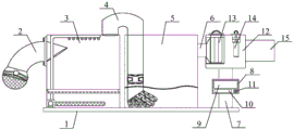
Fig. 2 is a schematic structural diagram of the present invention.
Figure 3 is a schematic structural view of the flue gas collection duct structure of the present invention.
Fig. 4 is a schematic structural diagram of the flue gas dust removal box structure of the invention.
Figure 5 is a schematic diagram of the construction of the preliminary smoke filter box of the present invention.
Fig. 6 is a schematic structural diagram of a secondary filtration purification frame structure of the present invention.
Fig. 7 is a schematic structural view of the smoke residue detection rod structure of the present invention.
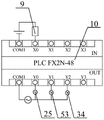
Fig. 8 is a schematic diagram of the electrical wiring of the present invention.
In the figure:
1. a base plate; 2. a flue gas collection duct structure; 21. a flange connecting plate; 22. a suction metal hose; 23. an air suction hood; 231. a dust filter screen; 24. a frame; 25. a fan; 26. an extraction fan blade; 3. a flue gas dust removal box structure; 31. a dust removal cooling box; 32. an intake splash duct; 33. a catheter; 34. a water pump; 35. a water pumping pipe; 351. a sponge dust filtration sleeve; 36. filtering a residue net; 37. an atomizing spray head; 4. a U-shaped smoke guide pipe; 5. a preliminary smoke filter box structure; 51. a preliminary filter box; 52. a breather tube; 53. a trapezoidal mounting bracket; 54. a double-shaft motor; 55. a blower blade; 56. a quartz sand layer; 57. a multi-stage conduit; 571. a vent hole; 6. an air duct; 7. a longitudinal support; 8. installing a frame; 9. a touch screen; 10. a controller; 11. a power switch; 12. a smoke guide frame; 13. a secondary filtering and purifying frame structure; 131. installing a shell; 132. an air inlet pipe; 133. an air outlet pipe; 134. a slot; 135. inserting plates; 1351. a handle; 1352. a protection plate; 1353. a sealing gasket; 136. a plurality of layers of activated carbon filter screens; 14. a smoke residue detection rod structure; 141. detecting the insertion cylinder; 142. a sealing piston; 143. detecting the casing pipe; 1431. PE dust-binding paper; 144. a connecting rod; 145. a cover plate; 146. a pull ring; 15. and (4) discharging the smoke tube.
Detailed Description
The invention is further described below with reference to the accompanying drawings:
in the figure:
as shown in figures 2 to 8
An environment-friendly chemical equipment waste gas treatment device comprises a bottom plate 1, a flue gas collecting guide pipe structure 2, a flue gas dedusting box structure 3, a U-shaped smoke guide pipe 4, a primary smoke filtering box structure 5, a gas guide pipe 6, a longitudinal support 7, an installation frame 8, a touch screen 9, a controller 10, a power switch 11, a smoke guide frame 12, a secondary filtering and purifying frame structure 13, a flue gas residue detection rod structure 14 and a smoke outlet pipe 15, wherein the flue gas collecting guide pipe structure 2 is installed on the upper portion of the left side of the flue gas dedusting box structure 3; the flue gas dust removal box structure 3 is arranged on the left side of the upper part of the bottom plate 1; the primary smoke filtering box structure 5 is arranged on the right side of the smoke dust removing box structure 3 and is arranged on the upper part of the bottom plate 1; the longitudinal support 7 is mounted on the right side of the upper part of the bottom plate 1 through bolts; the mounting frame 8 is mounted at the middle position of the front part of the longitudinal bracket 7 through screws; the touch screen 9 is embedded in the upper side of the front surface of the mounting frame 8; the controller 10 is embedded in the mounting frame 8; the power switch 11 is embedded in the right lower side of the front surface of the mounting frame 8; the smoke guide frame 12 is mounted at the upper end of the longitudinal support 7 through bolts; the secondary filtering and purifying frame structure 13 is arranged at the left upper part of the smoke guide frame 12; the smoke residue detection rod structure 14 is embedded in the right upper side of the interior of the smoke guide frame 12; the smoke outlet pipe 15 is arranged on the right side of the smoke guide frame 12 through bolts; the smoke residue detection rod structure 14 comprises a detection inserting cylinder 141, a sealing piston 142, a detection sleeve 143, a connecting rod 144, a cover plate 145 and a pull ring 146, wherein the outer wall of the detection inserting cylinder 141 is glued with the right upper side of the smoke guide frame 12; the sealing piston 142 is transversely inserted into the detection insert cylinder 141 and is glued to the outer side of the middle part of the connecting rod 144; the detection sleeve 143 is glued to the lower part of the connecting rod 144; the connecting rod 144 is glued to the middle lower part of the cover plate 145; the cover plate 145 is placed on the upper part of the detection insert cylinder 141; said tab 146 is glued to the upper middle portion of the cover plate 145.
Preferably, the flue gas collecting duct structure 2 comprises a flange connection disc 21, a suction metal hose 22, a suction hood 23, a frame 24, a fan 25 and a suction fan blade 26, wherein the suction metal hose 22 is welded on the left side of the flange connection disc 21; the air suction cover 23 is mounted at the left end of the air suction metal hose 22 through bolts; the frame 24 is mounted on the inner side wall of the air suction cover 23 through bolts; the fan 25 is mounted on the inner side of the frame 24 through bolts; the exhaust fan blade 26 is keyed on the lower output shaft of the fan 25.
Preferably, the secondary filtering and purifying frame structure 13 includes a mounting housing 131, an air inlet pipe 132, an air outlet pipe 133, a slot 134, an insert plate 135 and a multi-layer activated carbon filter screen 136, wherein the mounting housing 131 is bolted to the left upper side of the smoke guide frame 12; the air inlet pipe 132 is embedded in the left side of the middle part of the mounting shell 131; the air outlet pipe 133 is embedded in the right side of the middle part of the mounting shell 131; the slot 134 is longitudinally arranged in the middle of the mounting shell 131; the inserting plate 135 is inserted into the inserting groove 134; the multi-layer activated carbon screen 136 is longitudinally embedded in the lower portion of the insert plate 135.
Preferably, the flue gas dust removal box structure 3 comprises a dust removal and temperature reduction box 31, an air inlet anti-splash water guide pipe 32, a liquid guide pipe 33, a water suction pump 34, a water suction pipe 35, a filter residue net 36 and an atomizing spray nozzle 37, wherein the dust removal and temperature reduction box 31 is mounted on the upper part of the bottom plate 1 through bolts; the air inlet anti-splash conduit 32 is mounted on the left upper side of the inner wall of the dust-removing and temperature-reducing box 31 by bolts and is communicated with the air suction metal hose 22; the liquid guide pipe 33 is in threaded connection with a water outlet at the upper part of the water suction pump 34, and is glued to the top of the dedusting and cooling box 31 at the upper part; the water suction pump 34 is mounted at the left lower side inside the dedusting and cooling box 31 through bolts; the water pumping pipe 35 is inserted at the right water inlet of the water pumping pump 34; the filter residue screen 36 is transversely glued at the lower part of the inner side of the dedusting and cooling box 31; the atomizing nozzle 37 is sequentially screwed on the lower part of the right side of the liquid guide pipe 33 from left to right.
Preferably, said preliminary fume filter box structure 5 comprises a preliminary filter box 51, an air funnel 52, a trapezoidal mounting frame 53, a biaxial motor 54, a blowing fan 55, a quartz sand layer 56 and a multistage duct 57, said preliminary filter box 51 being bolted to the upper part of the base plate 1; the breather cylinder 52 is longitudinally inserted at the left side inside the primary filter box 51; the trapezoidal mounting frame 53 is mounted on the lower side of the inner wall of the air cylinder 52 through bolts; the double-shaft motor 54 is mounted on the inner side of the trapezoidal mounting frame 53 through bolts; the blowing fan blades 55 are respectively connected with the output shafts of the upper part and the lower part of the double-shaft motor 54 in a key mode; the quartz sand layer 56 is injected into the lower part of the inner side of the primary filter box 51; the multi-stage guide pipe 57 is inserted into the lower portion of the funnel 52.
Preferably, the inserting plate 135 is further provided with a handle 1351, a protection plate 1352 and a sealing washer 1353, and the handle 1351 is glued on the middle upper part of the protection plate 1352; the protection plate 1352 is glued to the upper end of the insertion plate 135; the sealing washer 1353 is glued to the outer side of the insert plate 135 at the connection with the protection plate 1352.
Preferably, a PE dust paper 1431 is further adhered to the outer side of the detection sleeve 143.
Preferably, a dust filter screen 231 is further disposed at the lower portion of the air suction hood 23, and the cross section of the dust filter screen 231 is semicircular.
Preferably, the multistage conduit 57 is provided with vent holes 571 at the outer side thereof, and a filter screen is further disposed at the inner side of the vent holes 571.
Preferably, the sponge dust filtering sleeve 351 is further sleeved on the outer side of the right part of the water pumping pipe 35.
Preferably, the flange plate 21 is bolted to the upper left side of the dust-removing and temperature-reducing box 31.
Preferably, the air duct 6 is bolted to the upper right side of the preliminary filtering tank 51 and the left side of the air inlet pipe 132 at the left and right ends, respectively.
Preferably, the U-shaped smoke guiding pipe 4 is respectively installed on the right side of the upper part of the dust-removing and temperature-reducing box 31 and the left side of the upper part of the preliminary filtering box 51 by bolts at both ends.
Preferably, the controller 10 specifically adopts FX2N-48 series PLC, and the touch screen 9 is electrically connected to an input end of the controller 10; the blower 25, the water pump 34 and the dual-axis motor 54 are respectively electrically connected with the output end of the controller 10.
The method for treating the waste gas of the environment-friendly chemical equipment comprises the following steps:
with particular reference to the description shown in figure 1
S101: collecting flue gas generated by chemical equipment, and collecting waste gas generated by the chemical equipment by using an air draft exhaust fan blade;
s102: dedusting the collected waste gas, guiding the extracted flue gas into a dedusting box, and extracting water liquid by using a water pump to spray the water liquid onto the flue gas in an atomizing nozzle to reduce dust;
s103: preliminarily filtering the dust-removed waste gas, and injecting the dust-reduced flue gas into quartz sand for preliminary filtering;
s104: carrying out secondary purification on the waste gas, and carrying out secondary filtration on the flue gas after primary purification by using an activated carbon net;
s105: finally, detecting particles in the waste gas, namely, dipping dust on the waste gas by using the PE dust-sticking paper, and manually observing the amount of the dust on the outer side of the PE dust-sticking paper to detect the amount of the particles;
s106: and (4) detecting the waste gas reaching the standard, discharging the purified flue gas from the flue gas outlet pipeline.
Preferably, in S104, the activated carbon net is specifically provided with three layers.
Principle of operation
The use method of the invention; firstly, clean water is injected into the dedusting and cooling box 31, the water level of the clean water is set at one third of the dedusting and cooling box 31, the touch screen 9 is controlled to control the fan 25 to rotate by the controller 10, the fan blade 26 is driven to rotate, waste gas generated by chemical equipment is extracted, then the waste gas is sucked into the dedusting and cooling box 31 through the air suction metal hose 22, meanwhile, the dust filter screen 231 is used for filtering large impurities in the adsorbed waste gas, then the touch screen 9 is controlled to control the water suction pump 34 by the controller 10 to extract water at the bottom of the dedusting and cooling box 31 through the water suction pipe 35, then the sponge dust filter sleeve 351 is used for extracting the water, then the water is downwards sprayed out of the atomizing nozzle 37 through the liquid guide pipe 33, so that smoke dust in the smoke is downwards precipitated, the filter screen 36 is used for filtering the water, and then the smoke enters the ventilation cylinder 52 through the U-shaped smoke guide pipe 4, when the touch screen 9 is controlled, the controller 10 controls the dual-shaft motor 54 to rotate, so that the dual-shaft motor drives the blowing fan blades 55 to rotate, the smoke entering from the U-shaped smoke guide pipe 4 is blown downwards and discharged through the vent holes 571 on the multi-stage guide pipe 57, the smoke is primarily filtered through the quartz sand layer 56, the filtered smoke enters the air inlet pipe 132 from the primary filter box 51 through the air guide pipe 6, then is discharged from the air outlet pipe 133, the smoke is secondarily filtered through the multi-layer activated carbon filter screen 136 between the air inlet pipe 132 and the air outlet pipe 133, finally the smoke is discharged from the smoke guide frame 12 and the smoke outlet pipe 15, the dust in the smoke is adsorbed by the PE sticky paper 1431 outside the detection sleeve 143 during discharge, then the pull ring 146 is pulled to pull the connecting rod 144 and the detection sleeve 143 out of the detection insertion cylinder 141 to penetrate through the dust on the PE sticky paper 1431, and the dust can be discharged outwards if no or little dust, if the amount of the smoke is large, the fan 25 is used for driving the exhaust fan blades 26 to rotate, so that the unqualified smoke is extracted, and the smoke is circulated again.
The technical solutions of the present invention or similar technical solutions designed by those skilled in the art based on the teachings of the technical solutions of the present invention are all within the scope of the present invention.
Claims (10)
1. The environment-friendly chemical equipment waste gas treatment device is characterized by comprising a bottom plate, a flue gas collecting guide pipe structure, a flue gas dedusting box structure, a U-shaped smoke guide pipe, a primary smoke filtering box structure, an air guide pipe, a longitudinal support, an installation frame, a touch screen, a controller, a power switch, a smoke guide frame, a secondary filtering and purifying frame structure, a flue gas residue detection rod structure and a smoke outlet pipe, wherein the flue gas collecting guide pipe structure is arranged at the upper part of the left side of the flue gas dedusting box structure; the flue gas dust removal box structure is arranged on the left side of the upper part of the bottom plate; the primary smoke filtering box structure is arranged on the right side of the smoke dust removing box structure and is arranged on the upper part of the bottom plate; the longitudinal support bolt is arranged on the right side of the upper part of the bottom plate; the mounting frame screw is mounted in the middle of the front part of the longitudinal support; the touch screen is embedded in the upper side of the front surface of the mounting frame; the controller is embedded in the mounting frame; the power switch is embedded in the right lower side of the front surface of the mounting frame; the smoke guide frame is installed at the upper end of the longitudinal support through a bolt; the secondary filtering and purifying frame structure is arranged at the left upper part of the smoke guide frame; the smoke residue detection rod structure is embedded in the right upper side of the interior of the smoke guide frame; the smoke outlet pipe bolt is arranged on the right side of the smoke guide frame; the smoke residue detection rod structure comprises a detection insertion cylinder, a sealing piston, a detection sleeve, a connecting rod, a cover plate and a pull ring, wherein the outer wall of the detection insertion cylinder is glued with the upper right side of the smoke guide frame; the sealing piston is transversely inserted into the detection insertion cylinder and is glued to the outer side of the middle part of the connecting rod; the detection sleeve is glued to the lower part of the connecting rod; the connecting rod is glued to the middle lower part of the cover plate; the cover plate is placed on the upper part of the detection insert cylinder; the pull ring is glued on the middle upper part of the cover plate.
2. The waste gas treatment device of the environment-friendly chemical equipment as claimed in claim 1, wherein the flue gas collecting duct structure comprises a flange connection disc, a suction metal hose, a suction hood, a frame, a fan and a suction fan blade, and the suction metal hose is welded on the left side of the flange connection disc; the air suction hood bolt is arranged at the left end of the air suction metal hose; the frame bolt is arranged on the inner side wall of the air suction cover; the fan bolt is arranged on the inner side of the frame; the exhaust fan blade is connected to the lower output shaft of the fan through a key.
3. The waste gas treatment device of the environment-friendly chemical equipment as claimed in claim 1, wherein the secondary filtering and purifying frame structure comprises a mounting shell, an air inlet pipe, an air outlet pipe, slots, inserting plates and a plurality of layers of activated carbon filter screens, and the mounting shell is mounted on the left upper side of the smoke guide frame through bolts; the air inlet pipe is embedded in the left side of the middle part of the mounting shell; the air outlet pipe is embedded in the right side of the middle part of the mounting shell; the slot is longitudinally arranged in the middle of the mounting shell; the inserting plate is inserted in the slot; the multilayer active carbon filter screen is longitudinally embedded in the lower part of the inserting plate.
4. The waste gas treatment device of the environment-friendly chemical equipment as claimed in claim 2, wherein the structure of the flue gas dust removal box comprises a dust removal and temperature reduction box, an air inlet anti-splash water guide pipe, a liquid guide pipe, a water suction pump, a water suction pipe, a filter residue net and an atomizing spray head, and the dust removal and temperature reduction box is mounted on the upper part of the bottom plate through bolts; the air inlet anti-splash conduit is mounted on the left upper side of the inner wall of the dust removal and temperature reduction box through a bolt and communicated with the air suction metal hose; the liquid guide pipe is in threaded connection with a water outlet at the upper part of the water suction pump, and the upper part of the liquid guide pipe is glued with the top of the dedusting and cooling box; the water suction pump is mounted at the left lower side inside the dedusting and cooling box through a bolt; the water pumping pipe is inserted at the water inlet on the right side of the water pumping pump; the filter residue net is transversely glued to the lower part of the inner side of the dedusting and cooling box; the atomization nozzle is sequentially connected with the lower part of the right side of the liquid guide pipe in a threaded manner from left to right.
5. The exhaust gas treatment device of the environment-friendly chemical equipment as claimed in claim 1, wherein the preliminary smoke filter box structure comprises a preliminary filter box, a breather pipe, a trapezoidal mounting rack, a double-shaft motor, a blower fan blade, a quartz sand layer and a multistage guide pipe, and the preliminary filter box is mounted on the upper part of the base plate through bolts; the air cylinder is longitudinally inserted into the left side of the interior of the primary filter box; the trapezoidal mounting frame bolt is arranged on the lower side of the inner wall of the breather cylinder; the double-shaft motor bolt is arranged on the inner side of the trapezoidal mounting frame.
6. The waste gas treatment device of the environment-friendly chemical equipment as claimed in claim 5, wherein the blowing fan blades are respectively connected with output shafts of the upper part and the lower part of the double-shaft motor in a key manner; the quartz sand layer is injected into the lower part of the inner side of the primary filter box; the multi-stage guide pipe is inserted at the lower part of the breather cylinder.
7. The exhaust gas treatment device of the environment-friendly chemical equipment as claimed in claim 3, wherein the plug board is further provided with a handle, a protection plate and a sealing washer, and the handle is glued at the middle upper part of the protection plate; the protective plate is glued at the upper end of the plug board; the sealing washer is glued at the joint of the outer side of the inserting plate and the protection plate.
8. The waste gas treatment device of the environment-friendly chemical equipment as claimed in claim 2, wherein a dust filter screen is further arranged at the lower part of the air suction hood, and the cross section of the dust filter screen is semicircular.
9. The method for treating the waste gas of the environment-friendly chemical equipment is characterized by comprising the following steps of:
the method comprises the following steps: collecting flue gas generated by chemical equipment, and collecting waste gas generated by the chemical equipment by using an exhaust fan blade;
step two: dedusting the collected waste gas, guiding the extracted flue gas into a dedusting box, and extracting water liquid by using a water pump to spray the water liquid onto the flue gas in an atomizing nozzle to reduce dust;
step three: preliminarily filtering the dust-removed waste gas, and injecting the dust-reduced flue gas into quartz sand for preliminary filtering;
step four: carrying out secondary purification on the waste gas, and carrying out secondary filtration on the flue gas after primary purification by using an activated carbon net;
step five: finally, detecting particles in the waste gas, namely, dipping dust on the waste gas by using the PE dust-sticking paper, and manually observing the amount of the dust on the outer side of the PE dust-sticking paper to detect the amount of the particles;
step six: and (4) detecting the waste gas reaching the standard, discharging the purified flue gas from the flue gas outlet pipeline.
10. The method for treating waste gas of environmental protection type chemical equipment according to claim 9, wherein in the fourth step, the activated carbon net is specifically provided with three layers.
Priority Applications (1)
| Application Number | Priority Date | Filing Date | Title |
|---|---|---|---|
| CN201810732026.3A CN108815967B (en) | 2018-07-05 | 2018-07-05 | Environment-friendly chemical equipment waste gas treatment device and operation method thereof |
Applications Claiming Priority (1)
| Application Number | Priority Date | Filing Date | Title |
|---|---|---|---|
| CN201810732026.3A CN108815967B (en) | 2018-07-05 | 2018-07-05 | Environment-friendly chemical equipment waste gas treatment device and operation method thereof |
Publications (2)
| Publication Number | Publication Date |
|---|---|
| CN108815967A CN108815967A (en) | 2018-11-16 |
| CN108815967B true CN108815967B (en) | 2020-11-10 |
Family
ID=64135732
Family Applications (1)
| Application Number | Title | Priority Date | Filing Date |
|---|---|---|---|
| CN201810732026.3A Active CN108815967B (en) | 2018-07-05 | 2018-07-05 | Environment-friendly chemical equipment waste gas treatment device and operation method thereof |
Country Status (1)
| Country | Link |
|---|---|
| CN (1) | CN108815967B (en) |
Families Citing this family (5)
| Publication number | Priority date | Publication date | Assignee | Title |
|---|---|---|---|---|
| CN109663418A (en) * | 2018-12-21 | 2019-04-23 | 江苏理文造纸有限公司 | A kind of papermaking dry air draft cleaning device |
| CN109781956A (en) * | 2019-03-16 | 2019-05-21 | 嘉兴勤慎智能技术有限公司 | A kind of coal gas monitoring sensor |
| CN110665325A (en) * | 2019-10-30 | 2020-01-10 | 邳州亚联环保科技有限公司 | Air dust removal purifies environmental protection equipment |
| CN110940775B (en) * | 2019-12-06 | 2022-05-17 | 吴开楠 | Standard detection device for exhaust emission |
| CN111167244B (en) * | 2019-12-30 | 2022-01-18 | 重庆皖渝纸制品有限公司 | Dust collector is used in carton processing |
Citations (4)
| Publication number | Priority date | Publication date | Assignee | Title |
|---|---|---|---|---|
| CN101823062A (en) * | 2010-04-15 | 2010-09-08 | 深南电路有限公司 | Dust-binding device |
| CN102928265A (en) * | 2012-10-22 | 2013-02-13 | 杭州富铭环境科技有限公司 | Smoke gas sampling method and device as well as smoke gas online monitoring system |
| CN203370427U (en) * | 2013-07-09 | 2014-01-01 | 南京中电环保科技有限公司 | Minitype efficient flue gas dedusting and desulfurizing device |
| CN104971614A (en) * | 2015-07-21 | 2015-10-14 | 天津霍普环保科技有限公司 | Pretreatment device of organic waste gas and use method of pretreatment device |
-
2018
- 2018-07-05 CN CN201810732026.3A patent/CN108815967B/en active Active
Patent Citations (4)
| Publication number | Priority date | Publication date | Assignee | Title |
|---|---|---|---|---|
| CN101823062A (en) * | 2010-04-15 | 2010-09-08 | 深南电路有限公司 | Dust-binding device |
| CN102928265A (en) * | 2012-10-22 | 2013-02-13 | 杭州富铭环境科技有限公司 | Smoke gas sampling method and device as well as smoke gas online monitoring system |
| CN203370427U (en) * | 2013-07-09 | 2014-01-01 | 南京中电环保科技有限公司 | Minitype efficient flue gas dedusting and desulfurizing device |
| CN104971614A (en) * | 2015-07-21 | 2015-10-14 | 天津霍普环保科技有限公司 | Pretreatment device of organic waste gas and use method of pretreatment device |
Also Published As
| Publication number | Publication date |
|---|---|
| CN108815967A (en) | 2018-11-16 |
Similar Documents
| Publication | Publication Date | Title |
|---|---|---|
| CN108815967B (en) | Environment-friendly chemical equipment waste gas treatment device and operation method thereof | |
| CN107894040A (en) | A kind of workshop air cleaning unit | |
| CN210186720U (en) | Boiler waste gas treatment device | |
| CN101138694A (en) | Complete environment protection fume purifying machine | |
| CN207539978U (en) | A kind of modularization lampblack purifying system | |
| CN206502781U (en) | A kind of temperature garbage pyrolysis system | |
| CN108532414B (en) | Asphalt mixture stirring environment-friendly treatment system and process | |
| CN101329079A (en) | Dual filtering type cooking fume exhauster | |
| CN2431514Y (en) | Secondary combustion kitchen range without fume exhausting | |
| CN207769482U (en) | A kind of sludge incineration tail gas processing system | |
| CN2695800Y (en) | Incineration purification furnace for house refuse | |
| CN107869749A (en) | A kind of multifunctional cooker hood | |
| CN2782201Y (en) | Integrated unit for treating waste gas and dusting | |
| CN208372651U (en) | A kind of chemical gases recyclable device | |
| CN204543618U (en) | Bitumen flue gas condensation cleaning treating apparatus | |
| CN2288000Y (en) | Toxicant-removing smoke-eliminating duster | |
| CN201249079Y (en) | Double filtering range hood | |
| CN207898386U (en) | A kind of fire-retardant baking car | |
| CN207006171U (en) | A kind of house refuse is decomposed and exhaust treatment system | |
| CN201289144Y (en) | Composite type purifying hood | |
| CN211462698U (en) | Spiral-flow type waste gas absorption tower | |
| CN213746742U (en) | Garbage pyrolysis flue gas collection device | |
| CN111023102A (en) | Environment-friendly facility for filtering waste gas | |
| CN205412541U (en) | Air -assisted ultrasonic wave micron order dry fog presses down dirt system | |
| CN208066040U (en) | Boiler smoke minimum discharge system |
Legal Events
| Date | Code | Title | Description |
|---|---|---|---|
| PB01 | Publication | ||
| PB01 | Publication | ||
| SE01 | Entry into force of request for substantive examination | ||
| SE01 | Entry into force of request for substantive examination | ||
| TA01 | Transfer of patent application right |
Effective date of registration: 20201015 Address after: 211500 No. 59 Wang Qiao Road, Xiongzhou Street, Liuhe District, Nanjing City, Jiangsu Province Applicant after: Nanjing worth Environmental Protection Technology Co.,Ltd. Address before: 214000 No. three, No. 99, Furong Road, Xishan Economic Development Zone, Jiangsu, Wuxi Applicant before: WUXI NANLIGONG TECHNOLOGY DEVELOPMENT Co.,Ltd. |
|
| TA01 | Transfer of patent application right | ||
| GR01 | Patent grant | ||
| GR01 | Patent grant |