Lower limb postoperative rehabilitation auxiliary walking robot
Technical Field
The invention relates to the technical field of surgical medical instruments, in particular to a lower limb postoperative rehabilitation auxiliary walking robot.
Background
In the surgery, the general low limbs carry out the operation, need carry out the rehabilitation training in the later stage recuperation, and comparatively serious patient then needs special nursing staff to nurse, still needs tools such as traditional walking stick or wheelchair when needs are walked simultaneously, and traditional tool can only realize helping the walking, and does not possess the function of supplementary rehabilitation training, can't satisfy the postoperative and resume the requirement.
Disclosure of Invention
In order to solve the problems, the invention provides a lower limb postoperative rehabilitation assisting walking robot which can well solve the problems.
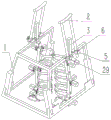
The technical scheme adopted by the invention is as follows: the utility model provides a recovered supplementary walking robot of low limbs postoperative, includes the frame, four angular position of frame lower part slide respectively and be provided with four branches, branch lower part and ten bytes wherein one end be connected, the cross-joint install on the track frame.
The left side and the right side of the upper part of the rack are respectively symmetrically provided with a height fixing rod, the lower part of the height fixing rod is provided with a front swing frame and a rear swing frame in a left-right sliding mode, the outer sides of the front swing frame and the rear swing frame are provided with front and rear thigh motors, the inner sides of the front and rear swing frames are rotatably provided with thigh angle pieces, one side of each thigh angle piece is connected with a front and rear thigh motor main shaft, the other side of each thigh angle piece is provided with a left and right thigh motor, and the inner sides of the thigh angle pieces; a thigh moving swing rod is slidably mounted in the thigh fixed swing rod, a front and rear crus motor is arranged on the outer side of the lower portion of the thigh moving swing rod, a crus corner piece is arranged on the inner side of the lower portion of the thigh moving swing rod, one side of the crus corner piece is connected with a front and rear crus motor spindle, a left and right crus motor is arranged on the other side of the crus corner piece, and a crus fixed swing rod is arranged on the inner side of the crus corner piece and connected with a left and; a calf movable swing rod is slidably mounted in the calf fixed swing rod, a sole left and right motor is arranged on the rear side of the lower portion of the calf movable swing rod, a sole corner piece is further arranged on the lower portion of the calf movable swing rod and connected with a sole left and right motor spindle, a sole front and rear motor is arranged on the outer side of the sole corner piece, a rear pedal is further arranged on the inner side of the sole corner piece, and the rear pedal is connected with the sole front and rear motor spindle; the front part of the rear pedal is provided with a front pedal; and the inner sides of the thigh fixed swing rod, the thigh movable swing rod, the crus fixed swing rod and the crus movable swing rod are respectively provided with a binding belt.
The left side and the right side of the upper part of the rack are respectively provided with two hinged supports, each hinged support is hinged with a hinged sleeve, and the two hinged sleeves on the same side are inserted with axilla branches.
Furthermore, a crawler and a driving motor are arranged on the crawler frame, and the driving motor drives the crawler to move.
Furthermore, four angular positions of the lower part of the rack are respectively provided with a supporting rod motor, a main shaft of the supporting rod motor is connected with a supporting rod gear, the upper part of the supporting rod is provided with a rack structure and is meshed with the supporting rod gear, and the supporting rod motor drives and adjusts the extending length of the supporting rod on the rack.
Furthermore, a controller and a display screen are arranged in front of the upper part of the rack.
Furthermore, a height fixing hole is formed in the upper portion of the height fixing rod, the height fixing rod is fixed on the rack through a height fixing pin inserted into the height fixing hole, and meanwhile the height fixing holes with different heights are used for adjusting the height of the height fixing rod relative to the rack.
Furthermore, an electric push rod is arranged in the thigh fixing swing rod and used for adjusting the position of the thigh moving swing rod in the thigh fixing swing rod.
Furthermore, an electric push rod is arranged in the lower leg fixed swing rod and used for adjusting the position of the lower leg movable swing rod in the lower leg fixed swing rod.
Furthermore, the front pedal and the rear pedal are provided with sole fixing rings.
Furthermore, the outer side of the hinge sleeve is provided with a fastening screw, the armpit support is provided with an adjusting threaded hole, the fastening screw is in threaded fit with the adjusting threaded hole to fix the armpit support in the hinge sleeve, and the adjusting threaded holes with different heights are used for adjusting the height of the armpit support relative to the rack.
Due to the adoption of the technical scheme, the invention has the following advantages: (1) the lower limb rehabilitation training device has the advantages that the lower limb is divided into the shank part and the thigh part for segmented rehabilitation training, and the front dimension, the back dimension, the left dimension and the right dimension and the length dimension are flexibly adjusted, so that the adaptability is strong; (2) according to the invention, the adjustable axillary branch and the lower limb training structure are mutually matched, so that a postoperative patient can use alone to perform lower limb rehabilitation auxiliary training; (3) the adjustable training device enables patients with different postoperative rehabilitation degrees to flexibly adjust the training intensity through the adjustable supporting rod and the adjustable crawler belt structure.
Drawings
Fig. 1 and 2 are schematic views of the overall assembly structure of the present invention from different viewing angles.
Fig. 3 to 6 are schematic assembled perspective views of some parts of the present invention.
Fig. 7 is a three-dimensional perspective view of the band of the present invention.
Fig. 8 is a schematic three-dimensional structure of the rack of the present invention.
Reference numerals: 1-a frame; 2-axillary branch; 3-a height fixing rod; 4-a height fixing pin; 5-tightening the screw; 6-reaming and sleeving; 7-front and back swing frame; 8-thigh front and back motors; 9-thigh left and right motors; 10-thigh fixed swing rod; 11-thigh swing rods; 12-a calf anterior posterior motor; 13-left and right shank motors; 14-a shank fixed swing rod; 15-a shank moving swing rod; 16-a strap; 17-rear pedal; 18-front foot pedal; 19-ten bytes; 20-a track frame; 21-a crawler belt; 22-a strut; 23-a strut motor; 24-strut gear; 25-a display screen; 26-a controller; 27-sole front and rear motor; 28-sole left and right motors; 29-free bearing; 30-sole fixing ring.
Detailed Description
The present invention will be further described with reference to specific examples, which are illustrative of the invention and are not to be construed as limiting the invention.
As shown in fig. 1 to 8, the lower limb postoperative rehabilitation auxiliary walking robot comprises a machine frame 1, four supporting rods 22 are respectively arranged at four angular positions of the lower part of the machine frame 1 in a sliding manner, the lower parts of the supporting rods 22 are connected with one end of a cross joint 19, and a cross joint 19 is arranged on a track frame 20.
The left side and the right side of the upper part of the rack 1 are respectively symmetrically provided with a height fixing rod 3, the lower part of the height fixing rod 3 is provided with a front swing frame 7 and a rear swing frame 7 in a left-right sliding mode, the outer side of the front swing frame 7 and the outer side of the rear swing frame 7 are provided with a front thigh motor 8 and a rear thigh motor 8, the inner side of the front swing frame 7 and the inner side of the rear swing frame 7 are rotatably provided with thigh angle parts, one side of each thigh angle part is connected with a main shaft of the front thigh motor 8 and the rear thigh; a thigh moving swing rod 11 is slidably mounted in the thigh fixing swing rod 10, a front and rear shank motor 12 is arranged on the outer side of the lower portion of the thigh moving swing rod 11, a shank corner piece is arranged on the inner side of the lower portion of the thigh moving swing rod 11, one side of the shank corner piece is connected with a main shaft of the front and rear shank motor 12, a left and right shank motor 13 is arranged on the other side of the shank corner piece, and a shank fixing swing rod 14 is arranged on the inner side of the shank corner piece and connected with a; a calf movable swing rod 15 is slidably mounted in the calf fixed swing rod 14, a sole left and right motor 28 is arranged on the rear side of the lower portion of the calf movable swing rod 15, a sole corner piece is further arranged on the lower portion of the calf movable swing rod 15 and is connected with a main shaft of the sole left and right motor 28, a sole front and rear motor 27 is arranged on the outer side of the sole corner piece, a rear pedal 17 is further arranged on the inner side of the sole corner piece, and the rear pedal 17 is connected with a main shaft of the sole front and rear motor 27; the front part of the rear pedal 17 is provided with a front pedal 18; the inner sides of the thigh fixed swing rod 10, the thigh movable swing rod 11, the shank fixed swing rod 14 and the shank movable swing rod 15 are all provided with a binding band 16.
The left side and the right side of the upper part of the frame 1 are respectively provided with two hinged supports 29, each hinged support 29 is hinged with a hinged sleeve 6, and the two hinged sleeves 6 on the same side are inserted with the axillary branches 2. The track frame 20 is provided with a track 21 and a driving motor, and the driving motor drives the track 21 to move. The four angular positions of the lower part of the rack 1 are respectively provided with a supporting rod motor 23, a supporting rod gear 24 is connected to a main shaft of the supporting rod motor 23, the upper part of the supporting rod 22 is provided with a rack structure and is meshed with the supporting rod gear 24, and the supporting rod motor 23 drives and adjusts the extending length of the supporting rod 22 on the rack 1.
The upper front position of the frame 1 is also provided with a controller 26 and a display screen 25. The upper part of the height fixing rod 3 is provided with a height fixing hole, the height fixing rod 3 is fixed on the rack 1 by inserting the height fixing pin 4 into the height fixing hole, and the height fixing holes with different heights are used for adjusting the height of the height fixing rod 3 relative to the rack 1. An electric push rod is arranged in the thigh fixed swing rod 10 and used for adjusting the position of the thigh movable swing rod 11 in the thigh fixed swing rod 10. An electric push rod is arranged in the lower leg fixed swing rod 14 and is used for adjusting the position of the lower leg movable swing rod 15 in the lower leg fixed swing rod 14. The front and rear footrests 18 and 17 are provided with sole fixing rings 30. The outer side of the hinge sleeve 6 is provided with a set screw 5, the axilla branch 2 is provided with an adjusting threaded hole, the set screw 5 is in threaded fit with the adjusting threaded hole to fix the axilla branch 2 in the hinge sleeve 6, and the adjusting threaded holes with different heights are used for adjusting the height of the axilla branch 2 relative to the rack 1.
The specific working process of the invention is as follows: firstly, a user fixes the lower limbs on a thigh fixed swing rod 10, a thigh movable swing rod 11, a crus fixed swing rod 14 and a crus movable swing rod 15 through binding bands respectively, and the lower limbs are adjusted through electric push rods arranged in the thigh fixed swing rod 10 and the crus fixed swing rod 14 according to the lengths of the thighs and the crus of the user; the crawler frame 20 and the crawler 21 form an auxiliary walking system for assisting the patient to walk; the two axilla branches are placed under the axilla of the user to play a supporting role; during the exercise, the thigh front and back motor 8, the thigh left and right motor 9, the shank front and back motor 12 and the shank left and right motor 13 are used for training the lower limbs.
The four height-adjustable crawler frames 20 are matched with the cross sections 19, so that the crawler frame has the capability of stably passing through various complex terrains, and a user can be ensured to keep an upright state no matter climbing or descending corners.