Detailed Description
The embodiments of the present application will be described below with reference to the drawings.
The following describes an image prediction method and a video encoding and decoding method provided by the embodiment of the present application. The main implementation of the image prediction method provided in the embodiments of the present application is a video encoding device or a video decoding device, which may be any device that needs to output or store video, such as a notebook computer, a tablet computer, a personal computer, a mobile phone, a video server, a digital television, a digital direct broadcast system, a wireless broadcast system, a Personal Digital Assistant (PDA), a laptop or desktop computer, an e-book reader, a digital camera, a digital recording device, a digital media player, a video game device, a video game console, a cellular or satellite radio telephone, a video conference device, a video streaming device, and so on. These digital video devices described above implement video compression techniques, such as those described in the standards defined by the MPEG-2, MPEG-4, ITU-T H.263, ITU-T H.264/MPEG-4 part 10 Advanced Video Coding (AVC), ITU-T H.265 High Efficiency Video Coding (HEVC) standards, and extensions of the standards, to more efficiently transmit and receive digital video information. Video devices may more efficiently transmit, receive, encode, decode, and/or store digital video information by implementing these video codec techniques.
In the field of video encoding and decoding, the concept of a frame refers to a complete image, and the image of one frame is composed of the images of one frame in a certain sequence and frame rate to form a video format, and then the video format can be played. When the frame rate reaches a certain speed, the interval time between two frames is less than the resolution limit of human eyes, and short visual retention occurs, so that the visual retention appears dynamically on the screen. The basis of the compression of a video file is the compression coding of a single-frame digital image, and a large amount of repeated representation information, called redundant information, exists in the digitized image. There are many places with the same or similar spatial structures in a frame of image, for example, there are mostly close relations and similarities between the colors of sampling points in the same object or background. In a multi-frame image group, an image of one frame is substantially greatly correlated with an image of a previous frame or a next frame, and the difference in pixel value of the description information is small, which are parts that can be compressed. For the same reason, the video file not only contains spatial redundant information, but also contains a large amount of temporal redundant information, which is caused by the composition structure of the video. For example, the frame rate of video samples is typically 25 frames/second to 30 frames/second, with the possibility of 60 frames/second in special cases. That is, the sampling time interval between two adjacent frames is at least 1/30 seconds to 1/25 seconds. In such a short time, a large amount of similar information exists in the sampled image pictures basically, and the pictures have great relevance. But are independent recordings in the original digital video recording system, these consistent similar characteristics are not considered and exploited, which results in a considerable amount of redundant data to repeat. In addition, it has been shown through research that, from the viewpoint of the psychological characteristic of the visual sensitivity of human eyes, there is also a portion of video information that can be used for compression, i.e., visual redundancy. Visual redundancy means that a video bitstream is appropriately compressed by using the victory property that the human eye is sensitive to luminance variations and relatively insensitive to chrominance variations. In the high-brightness area, the sensitivity of human vision to brightness change shows a descending trend, and the human vision is more sensitive to the edge of an object, and the inner area is relatively insensitive; the method is sensitive to the whole structure and relatively insensitive to internal detail transformation. Because the final service object of the video image information is a human group, the characteristics of human eyes can be fully utilized to compress the original video image information, and a better compression effect is achieved. In addition to the above-mentioned spatial redundancy, temporal redundancy, and visual redundancy, a series of redundant information of information entropy redundancy, structural redundancy, knowledge redundancy, importance redundancy, and the like exist in video image information. The purpose of video compression coding is to remove redundant information in a video sequence by using various technical methods so as to achieve the effects of reducing storage space and saving transmission bandwidth.
In terms of the current state of the art, video compression processing techniques mainly include intra-frame prediction, inter-frame prediction, transform quantization, entropy coding, and deblocking filtering. In the international general scope, there are four main compression encoding methods in the existing video compression encoding standards: chroma sampling, predictive coding, transform coding, and quantization coding.
Chroma sampling: the method makes full use of the psychovisual characteristics of human eyes, and tries to reduce the data volume of the single element description to the maximum extent from the data representation of the bottom layer. Most adopted in television systems is luminance-chrominance (YUV) color coding, which is a widely adopted standard for european television systems. The YUV color space includes a luminance signal Y and two color difference signals U and V, the three components being independent of each other. The mutually separated expression modes of the YUV color modes are more flexible, the transmission occupied bandwidth is less, and the model has more advantages than the traditional red, green and blue (RGB) color model. For example, the YUV4:2:0 form indicates that the two chrominance components U and V are only half of the luminance Y component in both the horizontal and vertical directions, i.e., there are 4 luminance components Y in 4 sample pixels, and there is only one chrominance component U and V. When this is expressed, the data amount is further reduced to about 33% of the original data amount. The aim of compressing video by using human physiological visual characteristics and the chrominance sampling mode is one of the video data compression modes widely adopted at present.
Predictive coding: i.e. the data information of previously encoded frames is used to predict the frame that is currently to be encoded. A predicted value is obtained through prediction, the predicted value is not completely equivalent to an actual value, and a certain residual value exists between the predicted value and the actual value. If the prediction is more suitable, the more the predicted value is close to the actual value, the smaller the residual value is, so that the data size can be greatly reduced by encoding the residual value, and the original image is restored and reconstructed by using the residual value and the predicted value when the decoding end decodes, which is the basic idea method of the prediction encoding. Predictive coding is divided into two basic types, intra-prediction and inter-prediction, in mainstream coding standards.
Transform coding: instead of directly encoding the original spatial domain information, the information sample values are converted from the current domain to another artificially defined domain (usually called transform domain) according to some form of transform function, and then compression encoding is performed according to the distribution characteristics of the information in the transform domain. Reasons for transform coding include: video image data is often large in data correlation in a spatial domain, so that a large amount of redundant information exists, and a large bit amount is required for direct encoding. And the data correlation in the transform domain is greatly reduced, so that the redundant information of the coding is reduced, and the data amount required by the coding is also greatly reduced, thereby obtaining higher compression ratio and realizing better compression effect. Typical transform coding is a Carlo (K-L) transform, a Fourier transform, or the like. Integer Discrete Cosine Transform (DCT) is a commonly used transform coding scheme in many international standards.
Quantization coding: the above mentioned transform coding does not compress data per se, and the quantization process is a powerful means for compressing data, and is also a main reason for data "loss" in lossy compression. The quantization process is a process of forcibly planning an input value with a large dynamic range into a small number of output values. Because the range of the quantized input value is large, more bits are needed for representation, and the range of the output value after forced programming is small, only a small number of bits are needed for representation. Each quantized input is normalized to a quantized output, i.e., quantized into an order of magnitude, commonly referred to as a quantization level (typically specified by the encoder).
In the coding algorithm based on the hybrid coding architecture, the compression coding modes are used in a hybrid way, and the encoder control module selects the coding mode adopted by different image blocks according to the local characteristics of the image blocks in the video frame. And performing frequency domain or spatial domain prediction on the intra-prediction coded block, performing motion compensation prediction on the inter-prediction coded block, performing transformation and quantization on a predicted residual error to form a residual error coefficient, and finally generating a final code stream through an entropy coder. To avoid accumulation of prediction errors, the reference signal for intra-frame or inter-frame prediction is obtained by a decoding module at the encoding end. And reconstructing a residual signal by the transformed and quantized residual coefficient through inverse quantization and inverse transformation, and adding the reconstructed residual signal and a predicted reference signal to obtain a reconstructed image.
In most coding frameworks, a video sequence consists of a series of pictures, which are further divided into slices, which are further divided into blocks. Video coding is performed in units of blocks, and the coding process can be performed from left to right and from top to bottom one line starting from the position of the upper left corner of a picture. Some new video coding standards extend the concept of block further. In the h.264 standard, there are Macroblocks (MB), which can be further divided into a plurality of prediction blocks (partition) that can be used for predictive coding.
In the high performance video coding (HEVC) standard, basic concepts such as a Coding Unit (CU), a Prediction Unit (PU), and a Transform Unit (TU) are used, and a plurality of units are functionally divided and described using a brand new tree-based structure. For example, a CU may be partitioned into smaller CUs according to a quadtree, and the smaller CUs may be further partitioned to form a quadtree structure. There is also a tree-like structure for PU and TU. A CU, a PU or a TU, essentially belongs to the concept of a block, and a CU, like a macroblock MB or a coding block, is a basic unit for dividing and coding a coded picture. The PU may correspond to a prediction block, which is a basic unit of prediction coding. The CU is further partitioned into PUs according to a partitioning pattern. A TU may correspond to a transform block, which is a basic unit for transforming a prediction residual. The HEVC standard may be referred to collectively as a Coding Tree Block (CTB), and so on.
In the HEVC standard, the size of a coding unit may include several size levels, 64 × 64, 32 × 32, 16 × 16, and 8 × 8, and the coding units of each level are divided into prediction units of different sizes according to intra prediction and inter prediction. For example, as shown in fig. 1-a and 1-B, fig. 1-a illustrates a partition manner of a prediction unit corresponding to intra prediction, and fig. 1-B illustrates several partition manners of a prediction unit corresponding to inter prediction.
In the scheme of the present application, mainly for intra-frame prediction scenarios, fig. 1-C show several possible adjacent reference blocks of a current block, where a reference block a is a left adjacent reference block of the current block, a reference block B is a left upper adjacent reference block of the current block, and a reference block C is an upper adjacent reference block of the current block.
In some aspects, an image prediction method may include: performing intra-frame prediction on a current block by using a reference block to obtain an initial prediction pixel value of a pixel point in the current block; and carrying out weighted filtering processing on the initial predicted pixel value of the pixel point in the current block by using the following weighted filtering formula so as to obtain the predicted pixel value of the pixel point in the current block.
Wherein, ccur=64-(ctop>>[y/d])-(cleft>>[x/d])+(ctopleft>>[x/d]) (formula 2)
Where equation 1 is one possible weighted filtering equation. ">" represents the shift operator.
In formula 1, ctopA weighting coefficient corresponding to a reconstructed pixel value of an upper neighboring reference block representing the current block, cleftA weighting coefficient corresponding to a reconstructed pixel value of a left neighboring reference block representing the current block, ctopleftAnd representing the weighting coefficient corresponding to the reconstructed pixel value of the upper left adjacent reference block of the current block. x represents the abscissa of a pixel point in the current block relative to the top left vertex of the current block, y represents the ordinate of a pixel point in the current block relative to the top left vertex of the current block, the coordinate of the top left vertex of the current block being, for example, [0,0 ]]. Wherein, p' [ x, y ″)]Representing coordinates [ x, y ] in the current block]P' x, y]Representing coordinates [ x, y ] in the current block]Of the pixel point of (1), r x-1]Representing coordinates [ x, -1 ] in an upper neighboring reference block of the current block]The pixel point of (1) reconstructs the pixel value, r [ -1, -1]Representing coordinates of [ -1, -1 ] in an upper left neighboring reference block of the current block]R-1, y of the pixel point of (a)]-1, y in a left neighboring reference block representing the current block]The reconstructed pixel value of the pixel point of (1).
Wherein the weighting coefficients used in the weighted filtering process include a horizontal weighting coefficient and a vertical weighting coefficient, and the horizontal weighting coefficient includes: c. Ctop. The vertical weighting coefficients include: c. CleftAnd ctopleft. Where d represents a decay rate factor, the decay rate factor applied to the horizontal weighting factor in equations 1 and 2 is equal to the decay rate factor applied to the vertical weighting factor, since d is applied to both the horizontal weighting factor and the vertical weighting factor.
Intra prediction is combined according to position dependence (english,abbreviations: PDPC), a weighted filtering formula needs to reflect the correlation existing between adjacent pixel points, and the correlation is attenuated by a relationship similar to an index as the distance between two points increases. For example, "> [ y/d in equation 1]"and" > [ x/d]"reflects the attenuation characteristics. Specifically, for example, if the coordinates (0,0) are adjacent to the positions of the two pixels (0, -1), then c is determined according to formula 1topThe reduction operation is not performed, so that the prediction result of the pixel point of the coordinate (0,0) is greatly influenced by r (0, -1).
The value of the decay rate factor d reflects the decay rate. As shown in fig. 1-D, in case that the size of the current block is 32x32, D is 2, and the coefficient c of the prediction pixel point a with the coordinate of (4,4)topAnd cleftAttenuated by a factor of 4 compared to the top left vertex. Coefficient c of prediction pixel point a of coordinate (4,4) where d is 1 in the case where the size of the current block is 8x8topAnd cleftAttenuated by a factor of 16 compared to the top left vertex. The pixel point a is near the top left in the CU of 32x32 and centered in the CU of 8x8, and its adjacency to the coordinate (0,0) point is relatively reduced. From the above analysis, it can be seen that a longer-side CU (e.g., side length)>32) coefficients decay slower than CU with shorter side length.
Recently, a quadtree plus binary tree (QTBT) division method has been proposed in the JVET conference. The QTBT method is characterized by comprising the following steps: non-square CUs that are not equal in length and width are allowed to appear; the length of one side of a CU ranges from 4 to 128.
In order to adapt to the QTBT method, the PDPC further adjusts the value of the attenuation speed factor d.
In one possible implementation, when the QTBT method is applied to partition a CU, the value of the decay rate factor d depends on the sum of the length and the width of the CU. For example, when the sum of the length and the width is less than 64, d is 1; when the sum of the length and the width is greater than or equal to 64, d is 2. The study finds that the scheme that the value of the attenuation speed factor d depends on the length-width sum of the CUs also has some problems, such as weak correlation between d and the CU shape when the length-width sum is equal and the value of d of CUs with different shapes is the same. As shown in fig. 1-E, the values of d are all 1 for CU of three sizes and shapes, 32x8, 8x32, and 16x 16. For another example, in a CU with a large aspect ratio, the values of d corresponding to the length and width are the same, i.e., the correlation between d and the length and width of the CU is weak. As shown in fig. 1-E, although the CU aspect ratios of 8x32 and 32x8 reach 1:4 or 4:1, since d is 1, the degrees of coefficient attenuation in both the length and width directions are considered to be identical; although the CU aspect ratios of 4x64 and 64x4 reach 1:8 or 8:1, since d takes the value of 2, the coefficient decay rates in both the length and width directions are considered to be identical.
In the above examples, in any case, the attenuation speed factor applied to the horizontal weighting coefficient is equal to the attenuation speed factor applied to the vertical weighting coefficient, so that in some cases, a large deviation occurs between the attenuation speed represented by the weighting filtering formula and the actual attenuation speed, thereby reducing the accuracy of image prediction, and further possibly greatly affecting the system encoding and decoding performance.
Other technical solutions are discussed further below.
Referring to fig. 2, fig. 2 is a flowchart illustrating an image prediction method according to an embodiment of the present disclosure, where the image prediction method can be applied to a video encoding process or a video decoding process, and the image prediction method specifically includes, but is not limited to, the following steps:
210. and carrying out intra-frame prediction on the current block by utilizing a reference block of the current block to obtain an initial prediction pixel value of a pixel point in the current block.
The intra-frame prediction is, for example, directional intra-frame prediction, direct current coefficient intra-frame prediction, interpolation intra-frame prediction, or other intra-frame prediction methods.
It can be appreciated that the manner in which the current block is intra-predicted using the reference block may be various.
Specifically, for example, the performing intra-frame prediction on the current block by using the reference block to obtain an initial predicted pixel value of a pixel point in the current block includes: carrying out filtering processing on the reconstructed pixel values of the reference pixels in the reference block to obtain filtered pixel values of the reference pixels in the reference block; and performing intra-frame prediction on the current block by using the filtering pixel value of the reference pixel point in the reference block to obtain an initial prediction pixel value of the pixel point in the current block.
For another example, the intra-frame predicting the current block by using the reference block to obtain the initial predicted pixel value of the pixel point in the current block includes: and carrying out intra-frame prediction on the current block by utilizing the reconstructed pixel value of the reference pixel point in the reference block to obtain the initial predicted pixel value of the pixel point in the current block.
220. And carrying out weighted filtering processing on the initial predicted pixel value of the pixel point in the current block to obtain the predicted pixel value of the pixel point in the current block. Wherein the weighting coefficients used in the weighted filtering process include a horizontal weighting coefficient and a vertical weighting coefficient, and a decay rate factor applied to the horizontal weighting coefficient is different from a decay rate factor applied to the vertical weighting coefficient.
Specifically, for example, in a case where the difference between the horizontal direction texture characteristic and the vertical direction texture characteristic of the current block exceeds a difference threshold, the attenuation speed factor applied to the horizontal weighting coefficient is different from the attenuation speed factor applied to the vertical weighting coefficient.
For another example, in a case that the difference between the horizontal texture characteristic and the vertical texture characteristic of the current block does not exceed the difference threshold, the attenuation speed factor applied to the horizontal weighting coefficient is the same as the attenuation speed factor applied to the vertical weighting coefficient.
It can be understood that, in the case that the difference between the horizontal direction texture characteristic and the vertical direction texture characteristic of the current block cannot be known in advance, the difference between the horizontal direction texture characteristic and the vertical direction texture characteristic of the current block may be determined, and then the attenuation speed factor applied to the horizontal weighting coefficient and the attenuation speed factor applied to the vertical weighting coefficient may be determined based on the determined difference between the horizontal direction texture characteristic and the vertical direction texture characteristic of the current block.
Of course, if the difference between the texture characteristics in the horizontal direction and the texture characteristics in the vertical direction of the current block is determined in advance (for example, if the texture characteristics are side lengths, and the current block is divided according to a specific dividing manner, the shape and the size of the current block are known determination parameters, and therefore, the difference between the length and the width of the current block is known determination parameters), it can also be considered that the attenuation speed factor acting on the horizontal weighting coefficient and the attenuation speed factor acting on the vertical weighting coefficient are correspondingly determined, and then it is not necessary to perform "determining the difference between the texture characteristics in the horizontal direction and the texture characteristics in the vertical direction of the current block first, and then determining the attenuation speed factor acting on the horizontal weighting coefficient and the attenuation speed factor acting on the vertical weighting coefficient based on the determined difference between the texture characteristics in the horizontal direction and the texture characteristics in the vertical direction of the current block Speed factor "is performed.
That is, in the case where it is known that the "difference between the horizontal direction texture characteristic and the vertical direction texture characteristic of the current block exceeds the difference threshold" is determined, or in the case where it is known that the "difference between the horizontal direction texture characteristic and the vertical direction texture characteristic of the current block does not exceed the difference threshold", it is not necessary to perform the condition determination as to whether the difference between the horizontal direction texture characteristic and the vertical direction texture characteristic of the current block exceeds the difference threshold ", but the attenuation speed factors acting on the horizontal weighting coefficients and the attenuation speed factors acting on the vertical weighting coefficients corresponding thereto may be selected directly according to the case of the current known determination.
It is to be understood that if the difference between the horizontal texture characteristic and the vertical texture characteristic of the current block exceeds the difference threshold, which indicates that the difference between the horizontal texture characteristic and the vertical texture characteristic of the current block is large, such difference should be considered, and if the difference between the horizontal texture characteristic and the vertical texture characteristic of the current block does not exceed the difference threshold, which indicates that the difference between the horizontal texture characteristic and the vertical texture characteristic of the previous block is small, such difference may be allowed to be ignored.
The decay rate factor acting on the horizontal weighting factor and the decay rate factor acting on the vertical weighting factor may be determined, for example, based on a difference between horizontal texture characteristics and vertical texture characteristics of the current block.
Texture characteristics may include, for example, side length, auto-variance, and/or edge sharpness, among others. Thus, the horizontal direction texture characteristics may include horizontal direction side length (long), horizontal direction self variance, and/or horizontal direction edge sharpness, etc.; the vertical texture characteristics may include vertical side length (width), vertical self variance, and/or vertical edge sharpness, among others.
For example, when the texture characteristic is a side length, the difference between the length and the width length of the current block exceeds a difference threshold, and the length of the current block is greater than the width, the attenuation speed factor applied to the horizontal weighting coefficient is greater than the attenuation speed factor applied to the vertical weighting coefficient; in the case where a difference between the length and the width of the current block exceeds a difference threshold and the length of the current block is smaller than the width, the attenuation velocity factor acting on the horizontal weighting coefficient is smaller than the attenuation velocity factor acting on the vertical weighting coefficient.
For another example, when the texture characteristic is a self-variance, if the difference between the horizontal direction self-variance and the vertical direction self-variance of the current block exceeds a difference threshold and the horizontal direction self-variance of the current block is greater than the vertical direction self-variance, the attenuation velocity factor acting on the horizontal weighting coefficient is greater than the attenuation velocity factor acting on the vertical weighting coefficient; and in the case that the difference between the horizontal direction self-variance and the vertical direction self-variance of the current block exceeds a difference threshold value and the horizontal direction self-variance of the current block is smaller than the vertical direction self-variance, the attenuation speed factor acting on the horizontal weighting coefficient is smaller than the attenuation speed factor acting on the vertical weighting coefficient.
For another example, when the texture characteristic is edge sharpness, then the rate of decay factor applied to the horizontal weighting factor is greater than the rate of decay factor applied to the vertical weighting factor if the dissimilarity between the horizontal edge sharpness and the vertical edge sharpness of the current block exceeds a dissimilarity threshold and the horizontal edge sharpness of the current block is greater than the vertical edge sharpness; in the case that a dissimilarity between a horizontal direction edge sharpness and a vertical direction edge sharpness of the current block exceeds a dissimilarity threshold, and the horizontal direction edge sharpness of the current block is smaller than the vertical direction edge sharpness, an attenuation speed factor acting on the horizontal weighting coefficient is smaller than an attenuation speed factor acting on the vertical weighting coefficient.
It will be appreciated that the decay rate factor reflects to some extent the decay rate of the applied weighting factor. The different decay rate factors may cause the decay rates of the applied weighting factors to exhibit differences. Whether the attenuation speed factor applied to the horizontal weighting coefficient is the same as the attenuation speed factor applied to the vertical weighting coefficient depends on the difference between the horizontal texture characteristic and the vertical texture characteristic of the current block.
For example, performing weighted filtering on the initial predicted pixel values of the pixels in the current block to obtain the predicted pixel values of the pixels in the current block may include: performing weighted filtering on the initial predicted pixel values of the pixels in the current block based on a weighted filtering formula to obtain the predicted pixel values of the pixels in the current block,
wherein, ccur=64-(ctop[y/d2])-(cleft>>[x/d1])+(ctooleft[x/d1]) (formula 4)
Wherein, formula 3 is a weighted filtering formula. ">" represents the shift operator.
Wherein, c istopBelonging to a horizontal weighting coefficient, said cleftAnd c is as describedtopleftBelonging to the vertical weighting coefficients.
Wherein, c istopReconstructing pixel value pairs of an upper neighboring reference block representing the current blockCorresponding weighting factor, said cleftA weighting coefficient corresponding to a reconstructed pixel value of a left neighboring reference block representing the current block, ctopleftAnd representing the weighting coefficient corresponding to the reconstructed pixel value of the upper left adjacent reference block of the current block. Wherein x represents the abscissa of the pixel point in the current block relative to the top left vertex of the current block, and y represents the ordinate of the pixel point in the current block relative to the top left vertex of the current block.
D is1For decay rate factors acting on horizontal weighting coefficients, said d2The d being a decay rate factor acting on the vertical weighting coefficient1And d is2Is a real number, p' [ x, y ]]Representing coordinates [ x, y ] in the current block]P' x, y]Representing coordinates [ x, y ] in the current block]Of the pixel point of (1), r x-1]Representing coordinates [ x, -1 ] in an upper neighboring reference block of the current block]The pixel point of (1) reconstructs the pixel value, r [ -1, -1]Representing coordinates of [ -1, -1 ] in an upper left neighboring reference block of the current block]R-1, y of the pixel point of (a)]-1, y in a left neighboring reference block representing the current block]The reconstructed pixel value of the pixel point of (1).
It can be understood that the values of the attenuation speed factor applied to the horizontal weighting coefficient and the attenuation speed factor applied to the vertical weighting coefficient mainly depend on the difference between the horizontal texture characteristic and the vertical texture characteristic of the current block, and the specific correspondence relationship between them may be various. Wherein the d is in a case that a disparity between a horizontal direction texture characteristic and a vertical direction texture characteristic of the current block exceeds a disparity threshold1Is not equal to d2In the case that the difference between the horizontal texture characteristic and the vertical texture characteristic of the current block does not exceed a difference threshold, the d1Is equal to d2。
The following exemplifies a case where the texture characteristic includes a side length.
For example, the d if the size of the current block is greater than a threshold thresh2 12, the length of the current block is less than or equal to a threshold threD in the case of sh21The thresh2 is a real number greater than or equal to 16. For example thresh2 is equal to 16, 17, 32, 64, 128 or other value.
As another example, the d is greater than the threshold thresh3 if the width of the current block is greater than the threshold 22, in case the width of the current block is less than or equal to a threshold thresh32The thresh3 is a real number greater than or equal to 16. For example thresh2 equals 16, 18, 32, 64, 128 or other values.
Specific example as shown in FIG. 1-F, in the example of FIG. 1-F, taking thresh2 and thresh2 equal to 16 as an example, d is the case of current blocks of sizes 32x8 and 64x41=2,d 21. D in case that the size of the current block is 16x161=1,d 21, d in case that the size of the current block is 8x32, 4x641=1,d 22. So set, for the current blocks of sizes 32x8, 64x4, the vertical weighting coefficient (c)top) Is a horizontal weighting coefficient (c)leftAnd ctopleft) One time of, for the current blocks of sizes 8x32, 4x64, the vertical weighting coefficient (c)top) Is a horizontal weighting coefficient (c)leftAnd ctopleft) Half of (1); for a current block d of size 16x161=d2=1,ctop、cleftAnd ctopleftThe same degree of attenuation. It can be seen that in this exemplary scenario, the decay rate of the coefficients can be adaptively changed according to the aspect ratio, shape, etc. of the image block.
As another example, when the texture characteristic comprises a side length, the disparity threshold comprises a threshold thresh1, in case the aspect ratio of the current block is greater than the threshold thresh1, e.g., d 11 and d 22; in case the width-to-length ratio of the current block is larger than the threshold thresh1, e.g. the d 12 and d 21, wherein the thresh1 is a real number greater than 2. For example thresh1 equals 2.5, 4, 6, 8, 16, 32, or other values.
Further, the aspect ratio of the current block is smaller than the threshold thresh1, and the current block is a current blockIn case that the length of the current block is greater than or equal to the width and the sum of the length and the width of the current block is greater than the threshold thresh4, d1=d 22. And/or, in case that the aspect ratio of the current block is less than the threshold thresh1, the length of the current block is greater than or equal to the width, and the sum of the length and the width of the current block is less than or equal to the threshold thresh4, the d1=d2=1。
Wherein thresh4 is a real number greater than or equal to 64, such as thresh4 being equal to 64, 65, 80, 96, 128, or other values.
Specific example as shown in fig. 1-G, in the example of fig. 1-G, the value d is given by taking thresh1 equal to 4 and thresh1 equal to 64 as an example, and the current block size is 32x8 and 64x41=2,d 21. D in the case of a current block size of 32x161=d 21. D in case of current block size of 64x321=d 22. So set, for the current blocks of sizes 32x8, 64x4, the vertical weighting coefficient (c)top) Is a horizontal weighting coefficient (c)leftAnd ctopleft) For a current block of size 32x16, 64x32, ctop、cleftAnd ctopleftThe same degree of attenuation. It can be seen that in this exemplary scenario, the decay rate of the coefficients can be adaptively changed according to the aspect ratio, shape, etc. of the image block.
It is to be understood that fig. 1-F and 1-G are merely exemplary of some possible embodiments, and certainly may not be limited to such exemplary embodiments in practical applications.
It can be seen that, in the above technical solution, the weighting coefficients used for performing weighted filtering processing on the initial predicted pixel values of the pixels in the current block include a horizontal weighting coefficient and a vertical weighting coefficient, and differential attenuation speed factors are set for the vertical weighting coefficient and the horizontal weighting coefficient, that is, the attenuation speed factor acting on the horizontal weighting coefficient may be different from the attenuation speed factor acting on the vertical weighting coefficient, which is beneficial to differentially controlling the attenuation speeds of the vertical weighting coefficient and the horizontal weighting coefficient, and is further beneficial to meeting some scene requirements that the vertical weighting coefficient and the horizontal weighting coefficient need to be attenuated at different attenuation speeds, and the flexibility of controlling the attenuation speeds of the vertical weighting coefficient and the horizontal weighting coefficient is enhanced, which is beneficial to improving the image prediction accuracy. For example, under the condition that the difference between the texture characteristics in the horizontal direction and the texture characteristics in the vertical direction of the current block exceeds a difference threshold value, the difference between the attenuation speed of the weighting coefficient and the difference between the texture characteristics are better matched, and the image prediction accuracy is further improved.
Referring to fig. 3, fig. 3 is a flowchart illustrating a video encoding method according to another embodiment of the present application, where the video encoding method specifically includes, but is not limited to, the following steps:
301. the video coding device carries out filtering processing on the reconstructed pixel values of the reference pixels in the reference block to obtain the filtered pixel values of the reference pixels in the reference block.
302. And the video coding device performs intra-frame prediction on the current block by using the filtering pixel value of the reference pixel point in the reference block to obtain an initial prediction pixel value of the pixel point in the current block.
The intra-frame prediction is, for example, directional intra-frame prediction, direct current coefficient intra-frame prediction, interpolation intra-frame prediction, or other intra-frame prediction methods.
303. The video encoding device determines an attenuation speed factor acting on a horizontal weighting coefficient and an attenuation speed factor acting on a vertical weighting coefficient based on a difference between a horizontal direction texture characteristic and a vertical direction texture characteristic of the current block.
It can be understood that, in the case that the difference between the horizontal direction texture characteristic and the vertical direction texture characteristic of the current block cannot be known in advance, the difference between the horizontal direction texture characteristic and the vertical direction texture characteristic of the current block may be determined, and then the attenuation speed factor applied to the horizontal weighting coefficient and the attenuation speed factor applied to the vertical weighting coefficient may be determined based on the determined difference between the horizontal direction texture characteristic and the vertical direction texture characteristic of the current block.
Of course, if the difference between the texture characteristics in the horizontal direction and the texture characteristics in the vertical direction of the current block is determined in advance (for example, if the texture characteristics are side lengths, and the current block is divided according to a specific dividing manner, the shape and the size of the current block are known determination parameters, and therefore, the difference between the length and the width of the current block is known determination parameters), it can also be considered that the attenuation speed factor acting on the horizontal weighting coefficient and the attenuation speed factor acting on the vertical weighting coefficient are correspondingly determined, and then it is not necessary to perform "determining the difference between the texture characteristics in the horizontal direction and the texture characteristics in the vertical direction of the current block first, and then determining the attenuation speed factor acting on the horizontal weighting coefficient and the attenuation speed factor acting on the vertical weighting coefficient based on the determined difference between the texture characteristics in the horizontal direction and the texture characteristics in the vertical direction of the current block Speed factor "is performed.
That is, in the case where it is known that the "difference between the horizontal direction texture characteristic and the vertical direction texture characteristic of the current block exceeds the difference threshold" is determined, or in the case where it is known that the "difference between the horizontal direction texture characteristic and the vertical direction texture characteristic of the current block does not exceed the difference threshold", it is not necessary to perform the condition determination as to whether the difference between the horizontal direction texture characteristic and the vertical direction texture characteristic of the current block exceeds the difference threshold ", but the attenuation speed factors acting on the horizontal weighting coefficients and the attenuation speed factors acting on the vertical weighting coefficients corresponding thereto may be selected directly according to the case of the current known determination.
Wherein, in a case where a difference between the horizontal direction texture characteristic and the vertical direction texture characteristic of the current block exceeds a difference threshold, the attenuation speed factor applied to the horizontal weighting coefficient is different from the attenuation speed factor applied to the vertical weighting coefficient, and in a case where the difference between the horizontal direction texture characteristic and the vertical direction texture characteristic of the current block does not exceed the difference threshold, the attenuation speed factor applied to the horizontal weighting coefficient is the same as the attenuation speed factor applied to the vertical weighting coefficient.
Texture characteristics may include, for example, side length, auto-variance, and/or edge sharpness, among others. Thus, the horizontal direction texture characteristics may include horizontal direction side length (long), horizontal direction self variance, and/or horizontal direction edge sharpness, etc.; the vertical texture characteristics may include vertical side length (width), vertical self variance, and/or vertical edge sharpness, among others.
It is understood that there is no necessary order between steps 301-302 and 303. Specifically, for example, the step 303 can be executed before, after or in synchronization with the execution of the steps 301-302.
304. And the video coding device carries out weighted filtering processing on the initial predicted pixel value of the pixel point in the current block so as to obtain the predicted pixel value of the pixel point in the current block. Wherein the weighting coefficients used by the weighted filtering process include the horizontal weighting coefficient and the vertical weighting coefficient.
The weighted filtering formula used for performing the weighted filtering process on the initial predicted pixel value of the pixel point in the current block in step 304 may be formula 3.
The specific manner of determining the attenuation speed factor acting on the horizontal weighting factor and the attenuation speed factor acting on the vertical weighting factor by the video encoding apparatus can refer to the related description of the embodiment corresponding to fig. 2, which is not repeated herein.
305. The video coding device obtains the prediction residual error of the current block based on the prediction pixel values of the pixel points in the current block. The video coding device can write the prediction residual of the current block into the video code stream.
It can be seen that, in the above exemplary video encoding scheme, the weighting coefficients used for performing the weighted filtering process on the initial predicted pixel values of the pixels in the current block include a horizontal weighting coefficient and a vertical weighting coefficient, and differential attenuation speed factors are set for the vertical weighting coefficient and the horizontal weighting coefficient, that is, the attenuation speed factor acting on the horizontal weighting coefficient may be different from the attenuation speed factor acting on the vertical weighting coefficient, which is beneficial to differentially controlling the attenuation speeds of the vertical weighting coefficient and the horizontal weighting coefficient, and is further beneficial to meeting some scene requirements that the vertical weighting coefficient and the horizontal weighting coefficient need to be attenuated at different attenuation speeds, and is beneficial to improving the accuracy of image prediction because the flexibility of controlling the attenuation speeds of the vertical weighting coefficient and the horizontal weighting coefficient is enhanced. For example, under the condition that the difference between the texture characteristics in the horizontal direction and the texture characteristics in the vertical direction of the current block exceeds a difference threshold value, the difference between the attenuation speed of the weighting coefficient and the difference between the texture characteristics are better matched, so that the image prediction accuracy is better improved, and the video decoding quality is better improved.
Referring to fig. 4, fig. 4 is a schematic flowchart of a video decoding method according to another embodiment of the present application, where the video decoding method specifically includes, but is not limited to, the following steps:
401. the video decoding device carries out filtering processing on the reconstructed pixel values of the reference pixels in the reference block to obtain the filtered pixel values of the reference pixels in the reference block.
402. And the video decoding device performs intra-frame prediction on the current block by using the filtering pixel value of the reference pixel point in the reference block to obtain an initial prediction pixel value of the pixel point in the current block.
The intra-frame prediction is, for example, directional intra-frame prediction, direct current coefficient intra-frame prediction, interpolation intra-frame prediction, or other intra-frame prediction methods.
403. The video decoding device determines an attenuation speed factor acting on a horizontal weighting coefficient and an attenuation speed factor acting on a vertical weighting coefficient based on a difference between a horizontal direction texture characteristic and a vertical direction texture characteristic of the current block.
Wherein, in a case where a difference between the horizontal direction texture characteristic and the vertical direction texture characteristic of the current block exceeds a difference threshold, the attenuation speed factor applied to the horizontal weighting coefficient is different from the attenuation speed factor applied to the vertical weighting coefficient, and in a case where the difference between the horizontal direction texture characteristic and the vertical direction texture characteristic of the current block does not exceed the difference threshold, the attenuation speed factor applied to the horizontal weighting coefficient is the same as the attenuation speed factor applied to the vertical weighting coefficient.
Texture characteristics may include, for example, side length, auto-variance, and/or edge sharpness, among others. Thus, the horizontal direction texture characteristics may include horizontal direction side length (long), horizontal direction self variance, and/or horizontal direction edge sharpness, etc.; the vertical texture characteristics may include vertical side length (width), vertical self variance, and/or vertical edge sharpness, among others.
It is understood that there is no necessary order between steps 401-402 and step 403. Specifically, for example, the step 303 can be executed before, after or in synchronization with the execution of the steps 401-402.
404. And the video decoding device carries out weighted filtering processing on the initial predicted pixel value of the pixel point in the current block so as to obtain the predicted pixel value of the pixel point in the current block. Wherein the weighting coefficients used by the weighted filtering process include the horizontal weighting coefficient and the vertical weighting coefficient.
In step 404, the weighted filtering formula used for performing weighted filtering on the initial predicted pixel value of the pixel point in the current block may be formula 3.
For a specific way of determining the attenuation speed factor acting on the horizontal weighting factor and the attenuation speed factor acting on the vertical weighting factor, reference may be made to the related description of the first embodiment, which is not repeated herein.
405. And the video decoding device reconstructs the current block based on the predicted pixel values and the predicted residual errors of the pixels in the current block.
The video decoding device can obtain the prediction residual error of the pixel point in the current block from the video code stream.
It can be seen that, in the above exemplary video decoding scheme, the weighting coefficients used for performing the weighted filtering process on the initial predicted pixel values of the pixels in the current block include a horizontal weighting coefficient and a vertical weighting coefficient, since the differential decay rate factors are set for the vertical weighting factors and the horizontal weighting factors, that is, the decay rate factor applied to the horizontal weighting factor may be different from the decay rate factor applied to the vertical weighting factor, this facilitates the differential control of the decay rates of the vertical weighting factors and the horizontal weighting factors, thereby being beneficial to meeting the requirements of some scenes that the vertical weighting coefficient and the horizontal weighting coefficient need to be attenuated according to different attenuation speeds, the flexibility of controlling the attenuation speed of the vertical weighting coefficient and the horizontal weighting coefficient is enhanced, so that the image prediction accuracy is favorably improved. For example, under the condition that the difference between the texture characteristics in the horizontal direction and the texture characteristics in the vertical direction of the current block exceeds a difference threshold value, the difference between the attenuation speed of the weighting coefficient and the difference between the texture characteristics are better matched, so that the image prediction accuracy is better improved, and the video decoding quality is better improved.
Through tests, compared with the related scheme using the formula 1, the scheme exemplified by fig. 2 to fig. 4 can bring about performance improvement of about 0.2% in the video sequence coding and decoding in some cases.
C of image blocks of size 8x32, 8x16topFor example, the difference between equation 1 and equation 3 will be described. Referring to fig. 5-a to 5-C, fig. 5-a illustrates C for an image block of size 8x32 in case equation 1 is usedtopC to the seventh row of pixelstopHas decayed to 0. FIG. 5-B illustrates c for an image block of size 8x16, using equation 1topC to the seventh row of pixelstopAlso attenuated to 0, which is associated with c of an image block of size 8x32topThe decay rates are substantially the same.
FIG. 5-C shows, by way of example, the case where equation 3 is used (in d)1=1,d 22 for example), c for image blocks of size 8x32topC to the eleventh row of pixelstopThe decay is 0. Therefore, the filtering degree of the predicted pixel value by using the formula 3 is relatively deeper, which is beneficial to improving the coding and decoding performance.
Lower pair oftopAnd cleftThe values of (a) are exemplified.
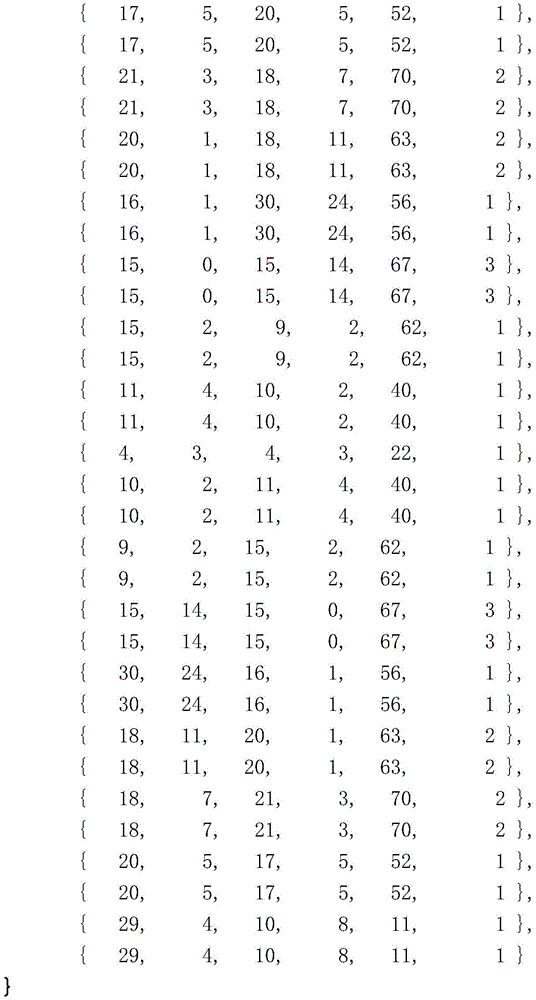
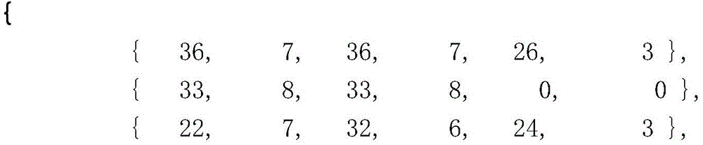
For example, if the image block has a length of 4, an array corresponding to the prediction direction may be selected from the following 35 arrays based on the prediction direction, and one of the 6 arrays may be selected as ctopThe value of (a). Similarly, if the width of the image block is 4, an array corresponding to the prediction direction may be selected from the following 35 arrays based on the prediction direction, and one of the 6 arrays may be selected as cleftThe value of (a).
For another example, if the image block has a length of 8, then an array corresponding to the prediction direction may be selected from the following 35 arrays based on the prediction direction, and one of the 6 arrays included in the array may be selected as ctopThe value of (a). Similarly, if the width of the image block is 8, an array corresponding to the prediction direction may be selected from the following 35 arrays based on the prediction direction, and one of the 6 arrays may be selected as cleftThe value of (a).
For another example, if the image block has a length of 16, then based on the prediction direction, an array corresponding to the prediction direction is selected from the following 35 arrays, and 1 of the 6 numbers included in the array is selected as ctopThe value of (a). Similarly, if the width of the image block is 16, thenBased on the prediction direction, 1 array corresponding to the prediction direction is selected from the following 35 arrays, and one of the 6 arrays included in the array is selected as cleftThe value of (a).
For another example, if the image block has a length of 32, then based on the prediction direction, an array corresponding to the prediction direction is selected from the following 35 arrays, and 1 of the 6 numbers included in the array is selected as ctopThe value of (a). Similarly, if the width of the image block is 32, based on the prediction direction, 1 array corresponding to the prediction direction is selected from the following 35 arrays, and one of the 6 arrays is selected as cleftThe value of (a).
For another example, if the image block has a length of 64, then based on the prediction direction, an array corresponding to the prediction direction is selected from the following 35 arrays, and 1 of the 6 numbers included in the array is selected as ctopThe value of (a). Similarly, if the width of the image block is 64, based on the prediction direction, 1 array corresponding to the prediction direction is selected from the following 35 arrays, and one of the 6 arrays is selected as cleftThe value of (a).
Of course, ctopAnd cleftCan also be other empirical values, ctopleftCan be based on ctopAnd cleftOther empirical values are also possible.
The following also provides a related apparatus for implementing the above-described scheme.
Referring to fig. 6, an embodiment of the present application provides an image prediction apparatus 600, including:
the prediction unit 610 is configured to perform intra prediction on a current block by using a reference block to obtain an initial predicted pixel value of a pixel point in the current block.
The intra-frame prediction is, for example, directional intra-frame prediction, direct current coefficient intra-frame prediction or interpolation intra-frame prediction.
A filtering unit 620, configured to perform weighted filtering processing on the initial predicted pixel value of the pixel point in the current block to obtain the predicted pixel value of the pixel point in the current block, where a weighting coefficient used in the weighted filtering processing includes a horizontal weighting coefficient and a vertical weighting coefficient, and an attenuation speed factor acting on the horizontal weighting coefficient is different from an attenuation speed factor acting on the vertical weighting coefficient.
Specifically, for example, in a case where the difference between the horizontal direction texture characteristic and the vertical direction texture characteristic of the current block exceeds a difference threshold, the attenuation speed factor applied to the horizontal weighting coefficient is different from the attenuation speed factor applied to the vertical weighting coefficient.
For another example, in a case that the difference between the horizontal texture characteristic and the vertical texture characteristic of the current block does not exceed the difference threshold, the attenuation speed factor applied to the horizontal weighting coefficient is the same as the attenuation speed factor applied to the vertical weighting coefficient.
Texture characteristics may include, for example, side length, auto-variance, and/or edge sharpness, among others. Horizontal texture characteristics may thus include horizontal side length (long), horizontal self-variance, and/or horizontal edge sharpness, etc.; the vertical texture characteristics may include vertical side length (width), vertical self variance, and/or vertical edge sharpness, among others.
For example, the prediction unit 610 is specifically configured to perform filtering processing on reconstructed pixel values of reference pixels in a reference block to obtain filtered pixel values of the reference pixels in the reference block; performing intra-frame prediction on the current block by using the filtering pixel value of the reference pixel point in the reference block to obtain an initial prediction pixel value of the pixel point in the current block; or performing intra-frame prediction on the current block by using the reconstructed pixel value of the reference pixel point in the reference block to obtain an initial predicted pixel value of the pixel point in the current block.
For example, the filtering unit is configured to perform weighted filtering on the initial predicted pixel values of the pixels in the current block based on a weighted filtering formula to obtain the predicted pixel values of the pixels in the current block,
wherein, ccur=64-(ctop>>[y/d2])-(cleft>>[x/d1])+(ctopleft>>[x/d1]),
Wherein, c istopBelonging to a horizontal weighting coefficient, said cleftAnd c is as describedtopleftBelonging to the vertical weighting coefficients.
Wherein, c istopA weighting coefficient corresponding to a reconstructed pixel value of an upper neighboring reference block representing the current block, cleftA weighting coefficient corresponding to a reconstructed pixel value of a left neighboring reference block representing the current block, ctopleftRepresenting a weighting coefficient corresponding to a reconstructed pixel value of an upper left adjacent reference block of the current block; x represents the abscissa of the pixel point in the current block relative to the top left vertex of the current block, and y represents the top left vertex of the pixel point in the current block relative to the current blockOrdinate of the point, d2For decay rate factors acting on horizontal weighting coefficients, said d1The d being a decay rate factor acting on the vertical weighting coefficient1And d is2Is a real number, p' [ x, y ]]Representing coordinates [ x, y ] in the current block]P' x, y]Representing coordinates [ x, y ] in the current block]Of the pixel point of (1), r x-1]Representing coordinates [ x, -1 ] in an upper neighboring reference block of the current block]The pixel point of (1) reconstructs the pixel value, r [ -1, -1]Representing coordinates of [ -1, -1 ] in an upper left neighboring reference block of the current block]R-1, y of the pixel point of (a)]-1, y in a left neighboring reference block representing the current block]The reconstructed pixel value of the pixel point of (1).
For example, the texture characteristic includes a side length, and the disparity threshold includes a threshold thresh 1.
In case that the aspect ratio of the current block is greater than the threshold thresh1, the d 11 and d 22; in case that the width-to-length ratio of the current block is greater than the threshold thresh1, the d 12 and d2The thresh1 is a real number greater than 2.
For another example, in the case that the aspect ratio of the current block is less than the threshold thresh1, and the length of the current block is greater than or equal to the width, and the sum of the length and the width of the current block is greater than the threshold thresh4, the d1=d 22; and/or, in case that the aspect ratio of the current block is less than the threshold thresh1, the length of the current block is greater than or equal to the width, and the sum of the length and the width of the current block is less than or equal to the threshold thresh4, the d1=d2=1。
Wherein the thresh4 is a real number greater than or equal to 64.
As another example, the texture characteristic includes a side length, where d is greater than a threshold thresh2 for the length of the current block 12, in case the length of the current block is less than or equal to a threshold thresh2 11, the thresh2 is a real number greater than or equal to 16; and/or, the width of the current block is larger than the thresholdD in the case of value thresh3 22, in case the width of the current block is less than or equal to a threshold thresh3 21, wherein the thresh3 is a real number greater than or equal to 16.
It is understood that the image prediction apparatus 600 can be applied to a video encoding apparatus or a video decoding apparatus, which can be any apparatus that needs to output or store video, such as a notebook computer, a tablet computer, a personal computer, a mobile phone, or a video server. The functions of the image prediction apparatus 600 in this embodiment can be realized based on the schemes of the above method embodiments, and some parts not described can refer to the above embodiments.
Referring to fig. 7, an embodiment of the present application provides an image prediction apparatus 700, including: including a processor 710 and a memory 720 coupled to each other. The memory 720 is used for storing instructions and data and the processor 710 is used for executing the instructions. The processor 710 is for example used to perform part or all of the steps of the methods in the above method embodiments.
Processor 710 is also referred to as a Central Processing Unit (CPU). The components of the image prediction apparatus in a particular application are coupled together, for example, by a bus system. The bus system may include a power bus, a control bus, a status signal bus, and the like, in addition to a data bus. For clarity of illustration, however, the various buses are designated in the figure as the bus system 730. The methods disclosed in the embodiments of the present application may be implemented in the processor 710 or implemented by the processor 710. The processor 710 may be an integrated circuit chip having signal processing capability. In some implementations, the steps of the above-described method may be performed by instructions in the form of hardware, integrated logic circuits, or software in the processor 710. The processor 710 may be a general purpose processor, a digital signal processor, an application specific integrated circuit, an off-the-shelf programmable gate array or other programmable logic device, discrete gate or transistor logic, discrete hardware components. Processor 710 may implement or perform the methods, steps, and logic blocks disclosed in the embodiments of the present application. The general purpose processor 710 may be a microprocessor or the processor may be any conventional processor or the like. The steps of the method disclosed in connection with the embodiments of the present application may be embodied directly in a hardware decoding processor, or in a combination of hardware and software modules in a decoding processor. The software modules may be located in ram, flash, rom, prom, or eprom, registers, etc. storage media as is well known in the art. The storage medium is located in the memory 720, and the processor 710 can read the information in the memory 720 and combine the hardware to perform the steps of the method.
For example, the processor 710 may be configured to perform intra prediction on a current block by using a reference block to obtain initial predicted pixel values of pixels in the current block; and performing weighted filtering processing on the initial predicted pixel value of the pixel point in the current block to obtain the predicted pixel value of the pixel point in the current block, wherein the weighting coefficient used in the weighted filtering processing comprises a horizontal weighting coefficient and a vertical weighting coefficient, and the attenuation speed factor acting on the horizontal weighting coefficient can be different from the attenuation speed factor acting on the vertical weighting coefficient.
Specifically, for example, in a case where the difference between the horizontal direction texture characteristic and the vertical direction texture characteristic of the current block exceeds a difference threshold, the attenuation speed factor applied to the horizontal weighting coefficient is different from the attenuation speed factor applied to the vertical weighting coefficient.
For another example, in a case that the difference between the horizontal texture characteristic and the vertical texture characteristic of the current block does not exceed the difference threshold, the attenuation speed factor applied to the horizontal weighting coefficient is the same as the attenuation speed factor applied to the vertical weighting coefficient.
It is understood that the image prediction apparatus 700 can be applied to a video encoding apparatus or a video decoding apparatus, which can be any apparatus that needs to output or store video, such as a notebook computer, a tablet computer, a personal computer, a mobile phone, or a video server. The functions of the image prediction apparatus 700 in this embodiment can be realized based on the schemes of the above method embodiments, and some parts not described can refer to the above embodiments.
Referring to fig. 8, fig. 8 is a schematic block diagram of a video encoder 20 that can be used in the embodiment of the present application, and includes an encoding-side prediction module 201, a transform quantization module 202, an entropy coding module 203, an encoding reconstruction module 204, and an encoding-side filtering module 205, and fig. 9 is a schematic block diagram of a video decoder 30 that can be used in the embodiment of the present application, and includes a decoding-side prediction module 206, an inverse transform inverse quantization module 207, an entropy decoding module 208, a decoding reconstruction module 209, and a decoding filtering module 210.
Video encoder 20 may be used to implement the image prediction methods or video encoding methods of embodiments of the present application. Video encoder 30 may be used to implement the image prediction methods or video decoding methods of embodiments of the present application. Specifically, the method comprises the following steps:
the encoding side prediction module 201 and the decoding side prediction module 206 are used to generate prediction data. Video encoder 20 may generate one or more Prediction Units (PUs) for each no longer partitioned CU. Each PU of a CU may be associated with a different block of pixels within a block of pixels of the CU. Video encoder 20 may generate a predictive block of pixels for each PU of the CU. Video encoder 20 may use intra prediction or inter prediction to generate the predictive pixel blocks for the PU. If video encoder 20 uses intra prediction to generate the predictive pixel block for the PU, video encoder 20 may generate the predictive pixel block for the PU based on decoded pixels of a picture associated with the PU. If video encoder 20 uses inter prediction to generate the predictive pixel block for the PU, video encoder 20 may generate the predictive pixel block for the PU based on decoded pixels of one or more pictures other than the picture associated with the PU. Video encoder 20 may generate residual blocks of pixels for the CU based on the predictive blocks of pixels for the PUs of the CU. The residual pixel block of the CU may indicate a difference between sample values in the predictive pixel block of the PU of the CU and corresponding sample values in the initial pixel block of the CU.
The transform quantization module 202 is configured to process the predicted residual data. Video encoder 20 may perform recursive quadtree partitioning on the residual pixel blocks of the CU to partition the residual pixel blocks of the CU into one or more smaller residual pixel blocks associated with Transform Units (TUs) of the CU. Because pixels in a block of pixels associated with a TU each correspond to one luma sample and two chroma samples, each TU may be associated with one block of luma residual samples and two blocks of chroma residual samples. Video encoder 20 may apply one or more transforms to a residual sample block associated with a TU to generate a coefficient block (i.e., a block of coefficients). The transform may be a DCT transform or a variant thereof. The coefficient block is obtained by applying a one-dimensional transform to calculate a two-dimensional transform in the horizontal and vertical directions using a transform matrix of the DCT. Video encoder 20 may perform a quantization procedure on each coefficient in the coefficient block. Quantization generally refers to the process by which coefficients are quantized to reduce the amount of data used to represent the coefficients, providing further compression. The inverse transform inverse quantization module 207 performs the inverse process of the transform quantization module 202.
Video encoder 20 may generate a set of syntax elements that represent coefficients in the quantized coefficient block. Video encoder 20, through entropy encoding module 203, may apply an entropy encoding operation (e.g., a Context Adaptive Binary Arithmetic Coding (CABAC) operation) to some or all of the syntax elements described above. To apply CABAC encoding to syntax elements, video encoder 20 may binarize the syntax elements to form a binary sequence including one or more bits (referred to as "bins"). Video encoder 20 may encode a portion of the bins using regular (regular) encoding and may encode other portions of the bins using bypass (bypass) encoding.
In addition to entropy encoding syntax elements of the coefficient block, video encoder 20, through encoding reconstruction module 204, may apply inverse quantization and an inverse transform to the transformed coefficient block to reconstruct a residual sample block from the transformed coefficient block. Video encoder 20 may add the reconstructed residual block of samples to a corresponding block of samples of the one or more predictive blocks of samples to generate a reconstructed block of samples. By reconstructing a block of samples for each color component, video encoder 20 may reconstruct a block of pixels associated with a TU. The pixel blocks for each TU of the CU are reconstructed in this manner until the entire pixel block reconstruction for the CU is complete.
After video encoder 20 reconstructs the pixel block of the CU, video encoder 20, through encoding-side filtering module 205, performs a deblocking filtering operation to reduce blockiness of the pixel block associated with the CU. While after video encoder 20 performs the deblocking filtering operation, video encoder 20 may modify the reconstructed pixel block of the CTB of the picture using Sample Adaptive Offset (SAO). After performing these operations, video encoder 20 may store the reconstructed block of pixels of the CU in a decoded picture buffer for use in generating predictive blocks of pixels for other CUs.
Video decoder 30 may receive the codestream. The code stream contains coding information of the video data coded by the video encoder 20 in the form of a bit stream. Video decoder 30, through entropy decoding module 208, parses the codestream to extract syntax elements from the codestream. When video decoder 30 performs CABAC decoding, video decoder 30 may perform regular decoding on some bins and may perform bypass decoding on other bins, where the bins in the bitstream have a mapping relationship with syntax elements, and the syntax elements are obtained by parsing the bins.
Among other things, the video decoder 30, through the decoding reconstruction module 209, may reconstruct pictures of the video data based on syntax elements extracted from the codestream. The process of reconstructing video data based on syntax elements is generally reciprocal to the process performed by video encoder 20 to generate syntax elements. For example, video decoder 30 may generate, based on syntax elements associated with the CU, predictive pixel blocks for PUs of the CU. In addition, video decoder 30 may inverse quantize coefficient blocks associated with TUs of the CU. Video decoder 30 may perform an inverse transform on the inverse quantized coefficient blocks to reconstruct residual pixel blocks associated with the TUs of the CU. Video decoder 30 may reconstruct the block of pixels of the CU based on the predictive block of pixels and the residual block of pixels.
After video decoder 30 reconstructs the pixel block of the CU, video decoder 30, through decode filter module 210, performs a deblocking filter operation to reduce blockiness of the pixel block associated with the CU. In addition, video decoder 30 may perform the same SAO operations as video encoder 20 based on the one or more SAO syntax elements. After video decoder 30 performs these operations, video decoder 30 may store the pixel blocks of the CU in a decoded picture buffer. The decoded picture buffer may provide reference pictures for subsequent motion compensation, intra prediction, and display device presentation.
Embodiments of the present application also provide a computer-readable storage medium, where the computer-readable storage medium stores program code, where the program code includes instructions for performing some or all of the steps of the method in the above method embodiments.
Embodiments of the present application also provide a computer program product, wherein when the computer program product runs on a computer, the computer is caused to execute some or all of the steps of the method as in the above method embodiments.
Embodiments of the present application also provide a computer program product, wherein when the computer program product runs on a computer, the computer is caused to execute some or all of the steps of the method as in the above method embodiments.
The present application further provides an application publishing platform, wherein the application publishing platform is configured to publish a computer program product, and when the computer program product runs on a computer, the computer is caused to perform some or all of the steps of the method in the above method embodiments.
Fig. 10 and 11 are two schematic block diagrams of an electronic device 50, the electronic device 50 incorporating a codec with which embodiments of the present application may be implemented. Fig. 11 is a schematic device diagram for video encoding according to an embodiment of the present application. The elements of fig. 10 and 11 will be described below.
The electronic apparatus 50 may for example be a mobile terminal or user equipment of a wireless communication system. It should be understood that embodiments of the present application may be implemented within any electronic device or apparatus that may require encoding and decoding, or encoding or decoding, of video images.
The apparatus 50 may include a housing 30 for incorporating and protecting equipment. The device 50 may also include a display 32 in the form of a liquid crystal display. In other embodiments of the present application, the display may be any suitable display technology suitable for displaying images or video. The apparatus 50 may also include a keypad 34. In other embodiments of the present application, any suitable data or user interface mechanism may be employed. For example, the user interface may be implemented as a virtual keyboard or a data entry system as part of a touch sensitive display. The device may include a microphone 36 or any suitable audio input, which may be a digital or analog signal input. The apparatus 50 may also include an audio output device, which in embodiments of the present application may be any one of the following: headphones 38, speakers, or analog audio or digital audio output connections. The apparatus 50 may also include a battery 40, and in other embodiments of the present application, the device may be powered by any suitable mobile energy device, such as a solar cell, a fuel cell, or a clock mechanism generator. The apparatus may also include an infrared port 42 for short-range line-of-sight communication with other devices. In other embodiments, the device 50 may also include any suitable short-range communication solution, such as a Bluetooth wireless connection or a USB/firewire wired connection.
The apparatus 50 may include a controller 56 or processor for controlling the apparatus 50. The controller 56 may be connected to a memory 58, which in embodiments of the present application may store data in the form of images and audio data, and/or may also store instructions for implementation on the controller 56. The controller 56 may also be connected to a codec circuit 54 adapted to effect encoding and decoding of audio and/or video data or ancillary encoding and decoding effected by the controller 56.
The apparatus 50 may also include a card reader 48 and a smart card 46, such as a UICC and UICC reader, for providing user information and adapted to provide authentication information for authenticating and authorizing a user at a network.
The apparatus 50 may further comprise a radio interface circuit 52 connected to the controller and adapted to generate wireless communication signals, for example for communication with a cellular communication network, a wireless communication system or a wireless local area network. The apparatus 50 may also include an antenna 44 connected to the radio interface circuit 52 for transmitting radio frequency signals generated at the radio interface circuit 52 to other apparatus(s) and for receiving radio frequency signals from other apparatus(s).
In some embodiments of the present application, the apparatus 50 includes a camera capable of recording or detecting single frames that are received and processed by the codec 54 or controller. In some embodiments of the present application, an apparatus may receive video image data to be processed from another device prior to transmission and/or storage. In some embodiments of the present application, the apparatus 50 may receive images for encoding/decoding via a wireless or wired connection.
The embodiments of the present application can be applied to various electronic apparatuses, and for example, an example in which the embodiments of the present application are applied to a television apparatus and a mobile phone apparatus is given below.
Fig. 12 is a schematic structural diagram of a television application to which the embodiment of the present application is applied.
The television apparatus 900 includes an antenna 901, a tuner 902, a demultiplexer 903, a decoder 904, a video signal processor 905, a display unit 906, an audio signal processor 907, a speaker 908, an external interface 909, a controller 910, a user interface 911, a bus 912, and the like.
Among them, the tuner 902 extracts a signal of a desired channel from a broadcast signal received via the antenna 901, and demodulates the extracted signal. The tuner 902 then outputs the encoded bit stream obtained by demodulation to the demultiplexer 903. That is, the tuner 902 is used as a transmitting device in the television apparatus 900 that receives an encoded stream of encoded images.
The demultiplexer 903 separates a video stream and an audio stream of a program to be viewed from the encoded bit stream, and outputs the separated streams to the decoder 904. The demultiplexer 903 also extracts auxiliary data, such as an electronic program guide, from the encoded bitstream and provides the extracted data to the controller 910. If the encoded bit stream is scrambled, the demultiplexer 903 may descramble the encoded bit stream.
The decoder 904 decodes the video stream and the audio stream input from the demultiplexer 903. The decoder 904 then outputs the video data generated by the decoding to the video signal processor 905. The decoder 904 also outputs audio data generated by decoding to an audio signal processor 907.
The video signal processor 905 reproduces the video data input from the decoder 904 and displays the video data on the display unit 906. The video signal processor 905 can also display an application picture provided via a network on the display unit 906. In addition, the video signal processor 905 may perform additional processing, e.g., noise removal, on the video data according to the setting. The video signal processor 905 can also generate an image of a GUI (graphical user interface) and superimpose the generated image on an output image.
The display unit 906 is driven by a driving signal supplied from the video signal processor 905, and displays a video or an image on a video screen of a display device such as a liquid crystal display, a plasma display, or an OELD (organic electroluminescent display).
The audio signal processor 907 performs reproduction processing, for example, digital-to-analog conversion and amplification, etc., on the audio data input from the decoder 904, and outputs audio through the speaker 908. In addition, the audio signal processor 907 may perform additional processing on the audio data, such as noise removal and the like.
The external interface 909 is an interface for connecting the television apparatus 900 with an external device or a network. For example, a video stream or an audio stream received via the external interface 909 may be decoded by the decoder 904. That is, the external interface 909 is also used as a transmission device in the television apparatus 900 that receives the encoded stream of the encoded image.
The controller 910 includes a processor and a memory. The memory stores programs to be executed by the processor, program data, auxiliary data, data acquired via a network, and the like. For example, when the television apparatus 900 is started, a program stored in the memory is read and executed by the processor. The processor controls the operation of the television apparatus 900 in accordance with control signals input from the user interface 911.
Wherein the user interface 911 is connected to the controller 910. For example, the user interface 911 includes buttons and switches for allowing the user to operate the television apparatus 900 and a receiving unit for receiving a remote control signal. The user interface 911 detects operations performed by a user via these components, generates control signals, and outputs the generated control signals to the controller 910.
The bus 912 connects the tuner 902, the demultiplexer 903, the decoder 904, the video signal processor 905, the audio signal processor 907, the external interface 909, and the controller 910 to each other.
In the television apparatus 900 having such a structure, the decoder 904 may have the function of the video decoding device or the image prediction device according to the above-described embodiments. For example, the decoder 904 may be configured to intra-predict a current block using a reference block to obtain initial predicted pixel values of pixels in the current block; and performing weighted filtering processing on the initial predicted pixel value of the pixel point in the current block to obtain the predicted pixel value of the pixel point in the current block, wherein the weighting coefficient used in the weighted filtering processing comprises a horizontal weighting coefficient and a vertical weighting coefficient, and the attenuation speed factor acting on the horizontal weighting coefficient is different from the attenuation speed factor acting on the vertical weighting coefficient.
Fig. 13 is a schematic structural diagram of a mobile phone application to which the embodiment of the present application is applied. The mobile phone device 920 may include an antenna 921, a communication unit 922, an audio codec 923, a speaker 924, a microphone 925, a camera unit 926, an image processor 927, a demultiplexer 928, a recording/reproducing unit 929, a display unit 930, a controller 931, an operation unit 932, a bus 933, and the like.
The antenna 921 is connected to the communication unit 922. A speaker 924 and a microphone 925 are connected to the audio codec 923. The operation unit 932 is connected to the controller 931. The bus 933 connects the communication unit 922, the audio codec 923, the camera unit 926, the image processor 927, the demultiplexer 928, the recording/reproducing unit 929, the display unit 930, and the controller 931 to one another.
The mobile phone device 920 performs operations in various operation modes, for example, transmission/reception of audio signals, transmission/reception of e-mail and image data, photographing of images, recording of data, and the like, including a voice call mode, a data communication mode, an imaging mode, and a video phone mode.
In the voice call mode, an analog audio signal generated by the microphone 925 is provided to the audio codec 923. The audio codec 923 converts the analog audio signal into audio data, performs analog-to-digital conversion on the converted audio data, and compresses the audio data. The audio codec 923 then outputs the audio data obtained as the compression result to the communication unit 922. Communication unit 922 encodes and modulates audio data to generate a signal to be transmitted. Communication unit 922 then transmits the generated signal to be transmitted to the base station via antenna 921. The communication unit 922 also amplifies a radio signal received via the antenna 921 and performs frequency conversion on the radio signal received via the antenna 921 to obtain a received signal. The communication unit 922 then demodulates and decodes the received signal to generate audio data, and outputs the generated audio data to the audio codec 923. The audio codec 923 decompresses the audio data and performs digital-to-analog conversion on the audio data to generate an analog audio signal. The audio codec 923 then provides the generated audio signals to the speaker 924 to output audio from the speaker 924.
In the data communication mode, for example, the controller 931 generates text data to be included in an electronic mail according to an operation by a user via the operation unit 932. The controller 931 also displays text on the display unit 930. The controller 931 also generates email data in response to an instruction for transmission from the user via the operation unit 932, and outputs the generated email data to the communication unit 922. Communication unit 922 encodes and modulates the e-mail data to generate a signal to be transmitted. Communication unit 922 then transmits the generated signal to be transmitted to the base station via antenna 921. The communication unit 922 also amplifies a radio signal received via the antenna 921 and performs frequency conversion on the radio signal received via the antenna 921 to obtain a received signal. The communication unit 922 then demodulates and decodes the received signal to restore the email data, and outputs the restored email data to the controller 931. The controller 931 displays the contents of the e-mail on the display unit 930 and stores the e-mail data in the storage medium of the recording/reproducing unit 929.
The recording/reproducing unit 929 includes a readable/writable storage medium. For example, the storage medium may be an internal storage medium, or may be an externally mounted storage medium, such as a hard disk, a magnetic disk, a magneto-optical disk, a USB (universal serial bus) memory, or a memory card.
In the imaging mode, the camera unit 926 images a subject to generate image data, and outputs the generated image data to the image processor 927. The image processor 927 encodes the image data input from the camera unit 926, and stores the encoded stream in a storage medium of the storage/reproduction unit 929.
In the video phone mode, the demultiplexer 928 multiplexes the video stream encoded by the image processor 927 and the audio stream input from the audio codec 923, and outputs the multiplexed stream to the communication unit 922. A communication unit 922 encodes and modulates the multiplexed stream to generate a signal to be transmitted. Communication unit 922 then transmits the generated signal to be transmitted to the base station via antenna 921. The communication unit 922 also amplifies a radio signal received via the antenna 921 and performs frequency conversion on the radio signal received via the antenna 921 to obtain a received signal. The signal to be transmitted and the received signal may comprise coded bit streams. The communication unit 922 then demodulates and decodes the received signal to restore the stream, and outputs the restored stream to the demultiplexer 928. The demultiplexer 928 separates a video stream and an audio stream from an input stream, outputs the video stream to the image processor 927, and outputs the audio stream to the audio codec 923. The image processor 927 decodes the video stream to generate video data. The video data is provided to the display unit 930, and a series of images are displayed by the display unit 930. The audio codec 923 decompresses the audio stream and performs digital-to-analog conversion on the audio stream to generate an analog audio signal. The audio codec 923 then provides the generated audio signals to the speaker 924 to output audio from the speaker 924.
In the mobile phone device 920 having such a structure, the image processor 927 has the functions of the video encoding device (video encoder, image prediction device) and/or the video decoding device (video decoder) according to the above-described embodiments.
For example, the image processor 927 may be configured to perform intra prediction on a current block using a reference block to obtain initial predicted pixel values of pixels in the current block; and performing weighted filtering processing on the initial predicted pixel value of the pixel point in the current block to obtain the predicted pixel value of the pixel point in the current block, wherein the weighting coefficient used in the weighted filtering processing comprises a horizontal weighting coefficient and a vertical weighting coefficient, and the attenuation speed factor acting on the horizontal weighting coefficient is different from the attenuation speed factor acting on the vertical weighting coefficient.
It should be appreciated that reference throughout this specification to "one embodiment" or "an embodiment" means that a particular feature, structure or characteristic described in connection with the embodiment is included in at least one embodiment of the present application. Thus, the appearances of the phrases "in one embodiment" or "in an embodiment" in various places throughout this specification are not necessarily all referring to the same embodiment. Furthermore, the particular features, structures, or characteristics may be combined in any suitable manner in one or more embodiments. Those skilled in the art should also appreciate that the embodiments described in this specification are all alternative embodiments and that the acts and modules involved are not necessarily required for this application.
In various embodiments of the present application, it should be understood that the size of the serial number of each process described above does not mean that the execution sequence is necessarily sequential, and the execution sequence of each process should be determined by its function and inherent logic, and should not constitute any limitation on the implementation process of the embodiments of the present application.
In addition, the terms "system" and "network" are often used interchangeably herein. It should be understood that the term "and/or" herein is merely one type of association relationship describing an associated object, meaning that three relationships may exist, for example, a and/or B, may mean: a exists alone, A and B exist simultaneously, and B exists alone. In addition, the character "/" herein generally indicates that the former and latter related objects are in an "or" relationship.
In the embodiments provided herein, it should be understood that "B corresponding to a" means that B is associated with a from which B can be determined. It should also be understood that determining B from a does not mean determining B from a alone, but may be determined from a and/or other information.
In the above embodiments, the implementation may be wholly or partially implemented by software, hardware, firmware, or any combination thereof. When implemented in software, may be implemented in whole or in part in the form of a computer program product. The computer program product includes one or more computer instructions. When loaded and executed on a computer, cause the processes or functions described in accordance with the embodiments of the application to occur, in whole or in part. The computer may be a general purpose computer, a special purpose computer, a network of computers, or other programmable device. The computer instructions may be stored in a computer readable storage medium or transmitted from one computer readable storage medium to another, for example, the computer instructions may be transmitted from one website, computer, server, or data center to another website, computer, server, or data center by wire (e.g., coaxial cable, fiber optic, digital subscriber line) or wirelessly (e.g., infrared, wireless, microwave, etc.). The computer-readable storage medium can be any available medium that can be accessed by a computer or a data storage device, such as a server, a data center, etc., that incorporates one or more of the available media. The usable medium may be a magnetic medium (which may be, for example, a floppy disk, a hard disk, a magnetic tape), an optical medium (such as an optical disk), a semiconductor medium (such as a solid state disk), or the like. In the foregoing embodiments, the descriptions of the respective embodiments have respective emphasis, and for parts that are not described in detail in a certain embodiment, reference may be made to related descriptions of other embodiments.
In the embodiments provided in the present application, it should be understood that the disclosed apparatus may be implemented in other manners. For example, the above-described embodiments of the apparatus are merely illustrative, and for example, the above-described division of the units is only one type of division of logical functions, and other divisions may be realized in practice, for example, a plurality of units or components may be combined or integrated into another system, or some features may be omitted, or not executed. In addition, the shown or discussed mutual coupling or direct coupling or communication connection may be through some interfaces, indirect coupling or communication connection of devices or units, and may be in an electrical or other form.
The units described as separate parts may or may not be physically separate, and parts displayed as units may or may not be physical units, may be located in one place, or may be distributed on a plurality of network units. Some or all of the units can be selected according to actual needs to achieve the purpose of the solution of the embodiment.
In addition, functional units in the embodiments of the present application may be integrated into one processing unit, or each unit may exist alone physically, or two or more units are integrated into one unit. The integrated unit can be realized in a form of hardware, and can also be realized in a form of a software functional unit.
The integrated units, if implemented as software functional units and sold or used as a stand-alone product, may be stored in a computer accessible memory. Based on such understanding, the technical solution of the present application, which is a part of or contributes to the prior art in essence, or all or part of the technical solution, may be embodied in the form of a software product, stored in a memory, including several requests for causing a computer device (which may be a personal computer, a server, a network device, or the like, and may specifically be a processor in the computer device) to execute all or part of the steps of the above-described method of the embodiments of the present application.
The above embodiments are only used for illustrating the technical solutions of the present application and not for limiting the same; although the present application has been described in detail with reference to the foregoing embodiments, it will be understood by those of ordinary skill in the art that: the technical solutions described in the foregoing embodiments may still be modified, or some technical features may be equivalently replaced; and such modifications or substitutions do not depart from the spirit and scope of the corresponding technical solutions in the embodiments of the present application.