CN108784792B - Sealing assembly and puncture outfit with same - Google Patents
Sealing assembly and puncture outfit with same Download PDFInfo
- Publication number
- CN108784792B CN108784792B CN201710299930.5A CN201710299930A CN108784792B CN 108784792 B CN108784792 B CN 108784792B CN 201710299930 A CN201710299930 A CN 201710299930A CN 108784792 B CN108784792 B CN 108784792B
- Authority
- CN
- China
- Prior art keywords
- sealing
- wall
- distal
- assembly
- slits
- Prior art date
- Legal status (The legal status is an assumption and is not a legal conclusion. Google has not performed a legal analysis and makes no representation as to the accuracy of the status listed.)
- Active
Links
Images


Classifications
-
- A—HUMAN NECESSITIES
- A61—MEDICAL OR VETERINARY SCIENCE; HYGIENE
- A61B—DIAGNOSIS; SURGERY; IDENTIFICATION
- A61B17/00—Surgical instruments, devices or methods, e.g. tourniquets
- A61B17/34—Trocars; Puncturing needles
-
- A—HUMAN NECESSITIES
- A61—MEDICAL OR VETERINARY SCIENCE; HYGIENE
- A61B—DIAGNOSIS; SURGERY; IDENTIFICATION
- A61B17/00—Surgical instruments, devices or methods, e.g. tourniquets
- A61B17/00234—Surgical instruments, devices or methods, e.g. tourniquets for minimally invasive surgery
-
- A—HUMAN NECESSITIES
- A61—MEDICAL OR VETERINARY SCIENCE; HYGIENE
- A61B—DIAGNOSIS; SURGERY; IDENTIFICATION
- A61B17/00—Surgical instruments, devices or methods, e.g. tourniquets
- A61B17/34—Trocars; Puncturing needles
- A61B17/3417—Details of tips or shafts, e.g. grooves, expandable, bendable; Multiple coaxial sliding cannulas, e.g. for dilating
- A61B17/3421—Cannulas
-
- A—HUMAN NECESSITIES
- A61—MEDICAL OR VETERINARY SCIENCE; HYGIENE
- A61B—DIAGNOSIS; SURGERY; IDENTIFICATION
- A61B17/00—Surgical instruments, devices or methods, e.g. tourniquets
- A61B17/00234—Surgical instruments, devices or methods, e.g. tourniquets for minimally invasive surgery
- A61B2017/00292—Surgical instruments, devices or methods, e.g. tourniquets for minimally invasive surgery mounted on or guided by flexible, e.g. catheter-like, means
- A61B2017/0034—Surgical instruments, devices or methods, e.g. tourniquets for minimally invasive surgery mounted on or guided by flexible, e.g. catheter-like, means adapted to be inserted through a working channel of an endoscope
-
- A—HUMAN NECESSITIES
- A61—MEDICAL OR VETERINARY SCIENCE; HYGIENE
- A61B—DIAGNOSIS; SURGERY; IDENTIFICATION
- A61B17/00—Surgical instruments, devices or methods, e.g. tourniquets
- A61B17/34—Trocars; Puncturing needles
- A61B17/3417—Details of tips or shafts, e.g. grooves, expandable, bendable; Multiple coaxial sliding cannulas, e.g. for dilating
- A61B2017/3419—Sealing means between cannula and body
Landscapes
- Health & Medical Sciences (AREA)
- Surgery (AREA)
- Life Sciences & Earth Sciences (AREA)
- Biomedical Technology (AREA)
- Nuclear Medicine, Radiotherapy & Molecular Imaging (AREA)
- Engineering & Computer Science (AREA)
- Heart & Thoracic Surgery (AREA)
- Medical Informatics (AREA)
- Molecular Biology (AREA)
- Animal Behavior & Ethology (AREA)
- General Health & Medical Sciences (AREA)
- Public Health (AREA)
- Veterinary Medicine (AREA)
- Pathology (AREA)
- Surgical Instruments (AREA)
Abstract
The invention discloses a sealing assembly for a puncture outfit, which comprises a sealing film and a puncture outfit, wherein the sealing film comprises a sealing hole, and the sealing film seals an instrument inserted into the sealing hole; a seal protector disposed adjacent to the sealing membrane for protecting the sealing membrane from damage by the instrument, the seal protector including at least one pressure plate; the pressure plate comprises a proximal opening and a distal hole, and a protective wall extending from the proximal opening to the distal hole; the protective wall includes at least two slits extending transversely from the distal aperture, the slits permitting deformation of the protective wall to expand the distal aperture to facilitate passage of the instrument therethrough. According to the sealing assembly of the puncture outfit, the sealing membrane can be effectively protected, the sealing membrane is prevented from being scratched or torn by sharp edges of the instrument, and the protecting wall of the sealing protector is simple in structure and small in number, so that the assembly is simple.
Description
Technical Field
The invention relates to a minimally invasive surgical instrument, in particular to a sealing assembly and a puncture outfit with the same.
Background
A puncture instrument is a surgical instrument used in minimally invasive surgery (especially hard-tube endoscopic surgery) for establishing an artificial passage into a body cavity. Typically consisting of a cannula assembly and a needle. The general clinical use mode is as follows: a small opening is cut in the patient's skin, and the needle is inserted through the cannula assembly, and then passed through the abdominal wall through the skin opening into the body cavity. Once inside the body cavity, the needle is removed, leaving the cannula assembly as a passage for the instrument into and out of the body cavity.
In endoscopic surgical procedures, insufflation fluids (e.g., carbon dioxide or saline) are typically infused into a patient's body cavity, thereby providing sufficient operating space for the procedure to be performed. The insufflated body cavity is typically under some pressure, which may be referred to as a pneumoperitoneum condition. To maintain pneumoperitoneum to ensure proper operation, the cannula assembly needs to be equipped with a seal assembly that generally prevents leakage of insufflation fluid when the endoscopic instrument is placed within the cannula.
The seal assembly includes a seal membrane assembly, wherein the seal membrane assembly includes a seal membrane and a seal membrane protector. The seal film protector is used for protecting the seal film from being damaged by surgical instruments and comprises a pressure pasting plate. When the surgical instrument enters the sleeve assembly, the front end of the surgical instrument enters the central hole of the sealing assembly and pushes the pressing plate, so that the hole diameter of the central hole is expanded to allow the tubular assembly of the surgical instrument to enter, and after the tubular assembly enters the sleeve assembly, the pressing plate circumferentially hoops the tubular assembly to match other sealing assemblies to maintain the pneumoperitoneum state. In the prior art, seal film protectors generally comprise four pressure plates, each of which has a sector of 90 ° to 180 °, the four pressure plates being overlapped and overlapped in sequence, i.e. a first portion of the first pressure plate is placed over a second portion of the second pressure plate, the first portion of the second pressure plate is placed over the second portion of the third pressure plate, the first portion of the third pressure plate is placed over the second portion of the fourth pressure plate, and the first portion of the fourth pressure plate is placed over the second portion of the first pressure plate, thereby defining a circular protective surface with a central hole. In such a design, the assembly process is relatively complex.
The four pressing plates are complex in structure, large in number and high in manufacturing cost; the assembly process of the pressing plate is relatively complicated, and the requirement on the proficiency of operators is high. In view of the above-described disadvantages, it is desirable to improve a seal film protector from the viewpoint of simplification of the structure and the assembly process.
Disclosure of Invention
The invention aims to provide a sealing component for a puncture outfit, which can realize the functions of sealing and sealing protection by a simpler structure and a simplified assembly process.
Based on the purpose, the technical scheme of the invention is as follows:
a seal assembly for a puncture instrument comprising a sealing membrane including a sealing aperture, the sealing membrane sealing against an instrument inserted into the sealing aperture; a seal protector disposed adjacent to the sealing membrane for protecting the sealing membrane from damage by the instrument, the seal protector including at least one pressure plate; the pressure plate comprises a proximal opening and a distal hole, and a protective wall extending from the proximal opening to the distal hole; the protective wall includes at least two slits extending transversely from the distal aperture, the slits permitting deformation of the protective wall to expand the distal aperture to facilitate passage of the instrument therethrough.
Furthermore, the protection wall comprises a first protection wall and a second protection wall which are connected, the first protection wall is conical, and the second protection wall is arc-shaped.
Further, the radian of the first protection wall is 360 degrees.
Preferably, the pressure plate comprises at least two second protection walls, and a gap is formed between the at least two second protection walls.
Preferably, the at least two second protective walls are uniformly disposed on the first protective wall.
Preferably, the pressure plate comprises two second protection walls, and the radian of each second protection wall is 90 degrees.
Further, the slit includes an open end located at a circumference of the distal end hole and a terminating end remote from the distal end hole, the terminating end being a circular hole.
Preferably, the at least two slits are evenly distributed along the circumference of the distal end hole.
Preferably, the protection wall is provided with 2 to 20 slits.
Preferably, the protection wall is provided with 6 slits, extension lines of the slits intersect at the center of the distal end hole, and every two adjacent slits form an included angle of 60 degrees.
Preferably, the pressure plate is integrally injection-molded by a thermoplastic elastomer.
Preferably, the seal protector includes two of the pressure plates, the two pressure plates being arranged to overlap, the slit of one of the pressure plates being covered by the protective wall of the other pressure plate except for the slit.
Preferably, the pressure pasting plate further comprises a mounting edge, the mounting edge extends transversely from the near-end opening, and a mounting hole for assembling the pressure pasting plate is formed in the mounting edge.
The invention also provides a puncture outfit comprising the sealing assembly, the puncture outfit further comprises a puncture core rod and a sleeve assembly, and the sealing assembly is arranged in the sleeve assembly.
The sealing assembly for the puncture outfit and the puncture outfit thereof comprise a sealing membrane and a sealing protector, wherein the sealing protector comprises a proximal opening, a distal hole and a protective wall extending from the proximal opening to the distal hole, and the sealing protector can effectively protect the sealing membrane and prevent the sealing membrane from being scratched or torn by the sharp edge of a surgical instrument inserted into the sealing protector; but also reduces the friction force passing through the sealing membrane during the insertion and extraction of the surgical instrument, thereby reducing the undesirable extension of the sealing membrane caused by the friction force; and the protective wall of the sealing protection piece has simple structure and small quantity, thereby leading the assembly process to be simple.
Drawings
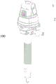
FIG. 1 is a schematic perspective view of a puncture instrument according to an embodiment of the present invention;
FIG. 2 is a schematic perspective view of a cannula assembly according to an embodiment of the present invention;
FIG. 3 is a perspective partial cross-sectional view of the cannula assembly of FIG. 2;
FIG. 4 is an exploded view of a sealing membrane assembly according to an embodiment of the invention;
FIG. 5 is a perspective partial cross-sectional view of a sealed membrane assembly according to an embodiment of the present invention;
FIG. 6 is a schematic structural view of a sealing film according to an embodiment of the present invention;
FIG. 7 is an exploded view of a seal protector according to an embodiment of the invention;
FIG. 8 is a schematic structural view of a seal protector according to an embodiment of the invention;
FIG. 9 is a bottom schematic view of a seal protector according to an embodiment of the invention.
Detailed Description
Reference will now be made in detail to embodiments of the present invention, examples of which are illustrated in the accompanying drawings. In the description of the present invention, it is to be understood that the terms "center", "longitudinal", "lateral", "length", "width", "thickness", "upper", "lower", "front", "rear", "left", "right", "vertical", "horizontal", "top", "bottom", "inner", "outer", "clockwise", "counterclockwise", "axial", "radial", "circumferential", etc., indicate orientations or positional relationships based on the orientation or positional relationships shown in the drawings.
Furthermore, the terms "first", "second" and "first" are used for descriptive purposes only and are not to be construed as indicating or implying relative importance or implicitly indicating the number of technical features indicated. Thus, a feature defined as "first" or "second" may explicitly or implicitly include at least one such feature. In the description of the present invention, "a plurality" means at least two, e.g., two, three, etc., unless specifically limited otherwise. The embodiments described below with reference to the drawings are illustrative and intended to be illustrative of the invention and are not to be construed as limiting the invention.
For greater ease of understanding, the side closer to the clinician's manipulator is set to be proximal, while the side further from the clinician's manipulator, i.e., the side closer to the patient's body, is set to be distal. With reference to FIG. 1, the top of the figure shows the end near the clinician's manipulator, which is the proximal end; while the lower side of the figure is the end that comes into contact with the patient's body, which is the distal end. Referring to fig. 1, there is shown an overall structure of a puncture instrument 100 according to a preferred embodiment of the present invention. A typical puncture instrument 100 comprises a puncture core assembly 1 and a cannula assembly 2, and in an initial state, the puncture core assembly 1 is inserted into the cannula assembly 2.
Fig. 2 and 3 are a schematic view of the entire structure of the cannula assembly 2 with the puncture assembly 1 removed and a partial sectional view thereof, respectively. The cannula assembly 2 has a proximal end 22 and a distal end 24, the proximal end 22 being outside the patient's body and the distal end 24 being inside the patient's body. In a typical application, the puncture core assembly 1 is passed through the cannula assembly 2, and the cannula assembly 2 is then brought together to penetrate the entire abdominal wall through the skin opening into the body cavity. After entering the body cavity, the puncture core assembly 1 is removed and the cannula assembly 2 is left as a passage for instruments into and out of the body cavity. A preferred sleeve assembly 2 includes a first seal assembly 3 and a second seal assembly 4. The clamping groove of the first sealing component 3 and the clamping hook of the second sealing component 4 are matched and fastened. The cooperation of trip and draw-in groove is the quick lock structure that can split fast. This is mainly to facilitate removal of tissue or foreign bodies from the patient during surgery. The quick-lock connection between the first seal assembly 3 and the second seal assembly 4 is achieved in a number of ways. Besides the structure shown in the embodiment, the structure can also adopt a threaded connection, a rotary buckle or other quick locking structures. Alternatively, the first seal assembly 3 and the second seal assembly 4 may be designed in a configuration that is not readily detachable.
Fig. 3 depicts the composition and assembled relationship of the first seal assembly 3. The lower housing 30 includes an elongated tube 31, the elongated tube 31 defining a sleeve 32 extending through the distal end 24 and being connected to a housing 33. The lower housing 30 has an inner wall 34 supporting a duckbill seal 36 and an air valve mounting aperture 35 communicating with the inner wall 34. The valve spool 350 is installed in the valve body 352 and together in the installation hole 35. The flange 362 of the duckbill seal 36 is sandwiched between the inner wall 34 and the lower cap 37. The fixing mode between the lower cover 37 and the lower shell 30 is various, and can adopt the modes of interference fit, ultrasonic welding, gluing, buckle fixing and the like. The 4 mounting posts of the lower cap 37 in this embodiment are an interference fit with the 4 mounting holes 35 of the lower housing 30, which interference fit places the duckbill seal 36 in compression. Referring to fig. 2 and 3, the sleeve 32, inner wall 34, duckbill seal 36, valve body 352 and valve core 350 together form a first chamber. In the present embodiment, the duckbill seal 36 is a single slit, but other types of closure valves, including flapper valves, multi-slit duckbill valves, may be used. The duckbill 360 can open when an external instrument is passed through the duckbill seal 36, but it does not normally provide a complete seal against the instrument. When the instrument is removed, the duckbill 360 automatically closes, thereby preventing fluid in the first chamber from leaking out of the body.
Fig. 3 also depicts the composition and assembled relationship of the second seal assembly 4. The second seal assembly 4 includes an upper cover 40, a seal membrane assembly 42 and an upper housing 41. The sealing membrane assembly 42 is sandwiched between the upper cover 40 and the upper case 41. The fixing mode between the upper shell 41 and the upper cover 40 is various, and can adopt the modes of interference fit, ultrasonic welding, gluing, buckling fixation and the like. In the present embodiment, the upper case 41 and the upper cover 40 are fixed by ultrasonic welding. This securement places the proximal end of the sealing membrane assembly 42 in compression.
Referring to fig. 4 and 5, the composition and assembled relationship of the sealing membrane assembly 42 is illustrated. The sealing membrane assembly 42 includes a lower fixing ring 420, a sealing membrane 5, a middle fixing ring 424, a protector 6, and an upper fixing ring 429. The sealing film 5 and the protector 6 are sandwiched between the lower fixing ring 420 and the upper fixing ring 429. Specifically, the lower fixing ring 420 is provided with a plurality of posts and holes, and correspondingly, the surface of the middle fixing ring 424 opposite to the lower fixing ring 420 is also provided with the same number of holes and posts, and the sealing membrane 5 is provided with a double number of holes, so that the posts of the lower fixing ring 420 pass through the holes of the sealing membrane 5 and are finally fixed in the corresponding holes of the middle fixing ring 424 during assembly, and the middle fixing ring 424 is fixed in the corresponding holes of the lower fixing ring 420 in the same manner. In addition, the surface of the middle fixing ring 424 facing the protector 6 is also provided with corresponding holes, so that the posts on the upper fixing ring 429 can pass through the sealing ring 428 and corresponding holes on the protector 6, and finally be fixed to the middle fixing ring 424, so that the sealing ring 428 and the protector 6 are locked to the middle fixing ring 424. The columns and the holes which are matched with each other are in interference fit.
The protector 6 comprises 2 sequentially overlapping protective sheets for protecting the sealing membrane 5 from being torn or torn by the sharp edges of the inserted surgical instrument. The sealing ring 428 is an elastic membrane comprising one or more radially (laterally) distributed annular corrugations which are laterally compliant so as to enable the entire sealing membrane assembly 42 to float in the second seal assembly 4. In this embodiment, the sealing diaphragm 5 and the sealing ring 428 are two separate parts, and in other embodiments, the sealing diaphragm 5 and the sealing ring 428 may be designed as a single unit to reduce the production cost, and in this case, the sealing diaphragm assembly 42 includes the lower fixing ring 420, the sealing diaphragm 5, the seal protector 6, and the upper fixing ring 429. The upper fixing ring 429 is provided with a plurality of pillars and holes, correspondingly, the surface opposite to the lower fixing ring 420 is also provided with the same number of holes and pillars, the sealing protector 6 is positioned above the integrated sealing film 5 and the sealing ring 428, the mounting edge 611 of the first pressing plate 61 and the mounting edge 621 of the second pressing plate 62 are mounted on the corresponding pillars, and the sealing film 5 and the sealing protector 6 are clamped between the lower fixing ring 420 and the upper fixing ring 429, so that the sealing protector 6 protects the sealing film 5 and prevents the sealing film from being punctured by an instrument. The columns and the holes which are matched with each other are in interference fit.
The sealing membrane assembly 42 may be made of many materials having different properties to meet the desired elasticity or strength requirements, respectively. For example, sealing membrane 5, sealing ring 428 is made of a relatively soft elastomeric material, such as a super-elastic material like silicone rubber, isoprene rubber, etc.; the protector 6 is made of semi-rigid thermoplastic elastomer, which is also called artificial rubber or synthetic rubber, and has the excellent performances of high elasticity, aging resistance and oil resistance of the traditional cross-linked vulcanized rubber, and has the characteristics of convenient processing and wide processing mode of common plastics. Preferably, the sealing protector 6 is made of TPU (thermoplastic polyurethane elastomer rubber), the TPU is wide in hardness range, good in rebound resilience and high in tear resistance, can deform when being acted by external force, and can recover the original shape when the external force disappears, so that the TPU can be always tightly attached to an instrument to protect the sealing film 5, and the sealing effect is further ensured. The upper retainer ring 429, the middle retainer ring 424 and the lower retainer ring 420 are made of a relatively rigid plastic material such as polycarbonate.
Fig. 4 and 6 are combined, wherein fig. 6 is a perspective view of the inner side of the sealing film 5. The sealing membrane 5 is an elastic membrane in its entirety, the sealing membrane 5 comprising a proximal opening 50, a distal aperture 52 and a sealing wall 54 extending from the distal aperture 52 towards the proximal opening 50. The distal aperture 52 is formed by a sealing lip for receiving an inserted instrument and forming an airtight seal. The sealing lip may be non-circular and as mentioned in the background of the invention the sealing lip circumference should be short and robust enough to ensure reliable sealing when 5mm instruments are used. The sealing lip in this example is circular. The sealing membrane 5 also comprises a radial flange 55, the sealing wall 54 being connected at one end to the sealing lip and at the other end to the radial flange 55. Wherein the sealing wall 54 comprises an annular wall portion 544 and a conical wall portion, the annular wall portion 544 being connected to the radial flange 55 and the conical wall portion connecting the sealing lip and the annular wall portion 544. As previously discussed, the radial flange 55 is provided with a plurality of small holes to facilitate sealing of the mounting of the diaphragm assembly 42. The sealing lip has an important function, namely: because the sealing lip has certain rigidity, when partial periphery of the sealing lip is acted by external force, the sealing lip can be deformed integrally, and the deformed periphery is kept to be approximately uniform in shape and size, so that the sealing lip can be always tightly attached to an instrument, and the sealing effect is ensured.
As shown in fig. 6, the conical wall portion of the sealing membrane 5 is overall of an inverted cone shape, the generatrix of the cone of which is set to be "transverse" in the direction from the distal end hole 52 to the radial flange 55. In this embodiment, the sealing wall 54 includes a plurality of pleat regions 51 circumscribing the distal bore 52 and extending transversely from the distal bore 52, the pleat regions 51 including at least one pleat element each extending from the distal bore 52 to an edge of the conical wall portion. Each pleat cell includes a pleat peak and a pleat valley, and the vertical distances from the pleat peak to the pleat valley of each pleat cell are equal over the entire length of the extension of the edge of the conical wall portion from the distal hole 52, and the minimum distances along the pleat wall from the pleat peak to the pleat valley are equal, i.e., the pleat shape of each pleat cell remains uniform, and the overall height of the pleat wall is uniform, so that the pleats are disposed on the sealing wall 54 without increasing the taper of the sealing wall 54, and the probability of the sealing membrane 5 inverting in the event of instrument withdrawal is reduced. Each of the pleat cells extends transversely from the sealing lip to the edge of the conical wall portion of the sealing wall 54, the sealing membrane 5 is an elastic membrane as a whole, and the pleats 51 serve to increase the elasticity and stretchability of the sealing lip. Preferably, the fold shapes of the fold units in all fold areas are the same, and the heights of the fold walls are the same. The sealing wall 54 further comprises flat regions 53, each flat region 53 extending in the transverse direction and being spaced between two adjacent corrugated regions 51, and each corrugated region 51 being spaced between two adjacent flat regions 53. Thus, the provision of the crimp region 51 at the distal aperture 52 increases the circumferential perimeter of the distal aperture 52, reducing the actual contact area between the instrument and the sealing membrane 5; allowing the sealing lips forming the distal aperture 52 to smoothly expand or contract to accommodate surgical instruments of different diameters while still maintaining a seal with the surgical instrument; and, due to the presence of the plurality of crimp units, lateral and vertical movement of the surgical instrument is permitted without loss of seal; and reduces hoop strain (stress) when large diameter instruments are used, thereby reducing the tightening force and frictional resistance to the instrument. The sealing wall 54 is also provided with a flat area 53, and the flat area 53 increases the tensile rigidity in the axial direction, so that the frictional resistance can be greatly reduced, the stick-slip can be improved, and the probability of the inward turning of the sealing film can be reduced.
Further, the sealing wall 54 comprises N sets of pleat areas 51 formed by said pleat cells, said N having a value ranging from 2 to 20; the sealing wall 54 is further provided with a flat area 53, and the corrugated area 51 and the flat area 53 are arranged at intervals; each of the pleat regions comprises 1 to 20 consecutive pleat cells. The circumferential perimeter of the distal end hole 52 can be increased, demoulding during manufacturing is facilitated, processing and manufacturing are facilitated, and materials are saved.
Each of the crimp regions 51 is symmetrically disposed, and a line of symmetry axis thereof intersects a central axis of the distal hole 52. The area of each flat area 53 is equal, and the area of each flat area 53 is larger than that of the corrugated area 51, so that demolding during manufacturing is facilitated, and processing and manufacturing are facilitated. Preferably, each of the pleat elements extends laterally from the distal aperture 52 to the edge of the conical wall portion of the seal wall 54, and each of the pleat elements extends laterally from the distal aperture and contacts the annular seal wall 544. The sealing membrane 5 is generally inverted conical to facilitate access to the distal end aperture 52 by surgical instruments. The sealing membrane 5 is formed by integrally injection molding a flexible material, preferably, the sealing membrane 5 is formed by integrally injection molding a flexible material, and the material of the sealing membrane is polyisoprene.
The seal protector 6 comprises a first protection wall and a second protection wall which are connected, the first protection wall is conical, and the second protection wall is arc-shaped. The direction in which the tapered generatrix extends from the distal end hole 63 toward the second protection wall, or in the direction perpendicular to the second protection wall, is set to "transverse". As shown in fig. 4, a seal protector 6 is provided adjacent to the sealing membrane 5 for protecting the central seal of the sealing membrane 5 from perforation or tearing by the sharp edges of an inserted surgical instrument. In an embodiment of the invention, and with reference to fig. 7 to 9, the seal protector 6 comprises at least one pressure strip. Preferably, the seal protector 6 comprises two said pressure plates: the first pressing plate 61 and the second pressing plate 62 are identical in shape, size and structure, and the first pressing plate 61 and the second pressing plate 62 are identical in shape, size and structure. Taking the first pressing plate 61 as an example, the first pressing plate 61 includes a first protection wall 616, a mounting edge 611, and a second protection wall 615 connecting the first protection wall 616 and the mounting edge 611, wherein the first protection wall 616 is tapered, and the second protection wall 615 is arc-shaped. Two second protection walls 615 are symmetrically arranged on the circumference of the first protection wall 616, the other end of each second protection wall 615 is connected with one mounting edge 611, the radians of the second protection walls 615 and the mounting edges 611 are equal, and the radians do not exceed 90 degrees. A gap 612 is formed between the two second protection walls 615, so that when the first pressing plate 61 and the second pressing plate 62 are overlapped, the second pressing plate 62 is rotated 90 degrees clockwise or counterclockwise, as shown in fig. 8, the two second protection walls 615 of the first pressing plate 61 are respectively located in the two gaps 622 of the second pressing plate 62, the two cylindrical protection walls 625 of the second pressing plate 62 are respectively located in the two gaps 612 of the first pressing plate 61, the second protection wall 615 and the mounting edge 611 of the first pressing plate 61 are not overlapped with the cylindrical protection wall 625 and the mounting edge 621 of the second pressing plate 62, and a conical protection wall and a conical mounting edge are formed together. Optionally, the radians of the second protection wall 615 and the mounting edge 611 are both equal to 90 degrees; thus, when the first pressure pasting board 61 and the second pressure pasting board 62 are overlapped, the second protection wall 615 and the mounting edge 611 of the first pressure pasting board 61 and the cylindrical protection wall 625 and the mounting edge 621 of the second pressure pasting board 62 can be overlapped and abutted against each other, together forming a 360-degree conical protection wall and a 360-degree mounting edge, so as to protect the annular wall portion 544 and the radial flange 55 of the seal wall 54 in a whole. Those skilled in the art will recognize that the curvature of the second protective wall 615 and the mounting edge 611 are shown for illustrative purposes only, and in fact the curvature may be any value no greater than 90 degrees, such as 30 degrees, 45 degrees, 60 degrees, etc., to achieve protection of the annular wall portion 544 and the radial flange 55 of the seal wall 54.
As shown in fig. 7, the first protection wall 616 is equally divided into N protection sheets 613 by N slits 614, wherein 2 ≦ N ≦ 20, and the slits 614 include an open end relatively close to the distal end hole 63 and a terminating end far from the distal end hole, which is provided as a circular hole 617, so as to prevent the slits 614 from undesirably extending beyond the terminating end, resulting in tearing of the first protection wall 616. A protective sheet 613 is formed between each two adjacent slits 614. The arc of the first protection wall 616 is 360 degrees, i.e., the N slits 614 and the N protection sheets 613 together form the 360-degree first protection wall 616. Preferably, the protection wall is provided with 6 slits 614, extension lines of the slits intersect at the center of the distal end hole, and an included angle of 60 ° is formed between two adjacent slits. In another embodiment of the present invention, 4 slits 614 are provided on the first protection wall 616, extension lines of the slits 614 intersect at the center of the distal hole, and two adjacent slits 614 form an included angle of 90 °. The above two preferred embodiments provide the preferred embodiments that can achieve the desired effect and at the same time can be easily formed, and of course, theoretical analysis and experimental tests show that the sealing protector 6 can effectively protect the sealing membrane 5 and prevent the sealing membrane 5 from being scratched or torn when the surgical instrument enters the body of the patient through the puncture device within the numerical range of N values of 2 to 20 (including two end values of 2 and 20).
The seal protector 6 comprises two same pressing plates, and the second pressing plate 62 is overlapped after being rotated clockwise or anticlockwise by 90 degrees relative to the first pressing plate 61 to form the seal protector 6 together; the overlapping arrangement comprises: the two cylindrical protection walls of one of the pressure sticking plates are positioned in the notch of the other pressure sticking plate, and the slit of one of the pressure sticking plates is covered by the protection plate of the other pressure sticking plate. As shown in fig. 8 or 9, the slit 614 of the first pressure plate 61 is covered with the protective sheet 623 of the second pressure plate 62, and the slit 624 of the second pressure plate 62 is covered with the protective sheet 613 of the first pressure plate 61, whereby the first pressure plate 61 and the second pressure plate 62 together form the seal protector 6, and the tapered surface of the first protective wall is formed into a seamless tapered surface except for the distal end hole 63, thereby protecting the seal film 5.
The seal protector 6 comprises a proximal opening and a distal bore 63, and a protective wall extending from the proximal opening to the distal bore 63. Taking the first pressure plate 61 as an example, the protection wall 616 includes at least two slits 614 extending transversely from the distal hole 63, the slits 614 being configured to allow the protection wall 616 to deform to expand the distal hole 63, thereby facilitating the passage of surgical instruments through the distal hole 63. In this process, the N protective sheets 613 along the circumference of the distal hole 63 still cling to the outer circumference of the device, assisting the sealing membrane in maintaining the pneumoperitoneum. The slit 614 includes an open end relatively close to the distal bore 63 and a terminating end remote from the distal bore, the terminating end being a circular aperture 617, the circular aperture 617 preventing the slit 614 from extending beyond the terminating end when a surgical instrument is inserted into or withdrawn from the penetrator. The sealing membrane assembly 42 comprises a sealing membrane 5 and a sealing protector 6, wherein the sealing protector 6 is arranged close to the sealing membrane 5 and is positioned at the proximal end of the sealing membrane 5, when a surgical instrument is inserted into the puncture outfit, the surgical instrument firstly contacts the sealing protector 6 and enters the distal end hole 52 of the sealing membrane 5 from the distal end hole 63 of the sealing protector 6, the sealing protector 6 is made of TPU material and has better resilience, namely, the characteristic of good recoverability after external force is removed, the protection sheet 611 along the circumferential direction of the distal end hole 63 is still tightly attached to the periphery of the instrument, and the auxiliary sealing membrane plays a role in maintaining the pneumoperitoneum state. The sealing membrane assembly 42 comprises a sealing membrane 5 and a sealing protector 6, the first protection wall of the sealing protector 6 is in the shape of an inverted cone when no surgical instrument is inserted into the puncture instrument; the seal protector 6 is disposed adjacent to the sealing membrane 5 and at the proximal end of the sealing membrane 5. When a surgical instrument is inserted into the puncture instrument, the sharp edge of the surgical instrument contacts the seal protector 6 first, enters the distal hole 52 of the sealing membrane 5 from the distal hole 63 of the seal protector 6, and the protection plates are separated from the adjacent protection plates respectively under the action of external force, and the conical protection wall of the seal protector 6 can effectively prevent the sealing membrane 5 from being scratched or torn by the sharp edge of the surgical instrument. When the surgical instrument is withdrawn from the puncture outfit, the external force disappears gradually, and the sealing protection piece 6 is made of TPU material, so that the puncture outfit has the characteristics of better rebound resilience, namely good recoverability after the external force is removed, wherein the slit of one pressing plate is covered by the protection piece of the other pressing plate, and the first protection wall is gradually restored to be in an inverted cone shape to form the protection of the sealing film 5; the conical protective wall of the seal protector 6 effectively prevents the sealing membrane 5 from being torn or torn by the sharp edges of the surgical instrument.
The present invention provides an improved seal protector 6, seal membrane 5, seal membrane assembly 42 including the seal protector 6, seal assembly 4 including the seal membrane assembly 42, and puncture outfit 100 including the seal assembly 4. it is understood that the seal protector 6, seal assembly 4 including the seal protector 6, and puncture outfit 100 including the seal assembly 4 having the aforementioned features are the subject matter of the present invention, and any changes, modifications, substitutions, and alterations based on the above embodiments are within the scope of the invention as claimed. According to the sealing assembly for the puncture outfit and the puncture outfit thereof, the sealing protector 6 comprises a proximal opening and a distal hole, and a protective wall extending from the proximal opening to the distal hole, the sealing protector 6 can effectively protect the sealing membrane 5 and prevent the sealing membrane 5 from being scratched or torn by the sharp edge of the inserted surgical instrument; but also reduces the friction through the sealing membrane 5 during insertion and extraction of the surgical instrument, and thus reduces 7 the undesirable extension of the sealing membrane 5 carried along by the friction; and the protective wall of the seal protection member 6 is simple in structure and small in number, thereby making the assembly process simple.
In the description of the present invention, it is to be understood that the terms "central," "longitudinal," "lateral," "length," "width," "thickness," "upper," "lower," "front," "rear," "left," "right," "vertical," "horizontal," "top," "bottom," "inner," "outer," "clockwise," "counterclockwise," "axial," "radial," "circumferential," and the like are used in the orientations and positional relationships indicated in the drawings for convenience in describing the invention and to simplify the description, and are not intended to indicate or imply that the referenced devices or elements must have a particular orientation, be constructed and operated in a particular orientation, and are therefore not to be considered limiting of the invention.
Furthermore, the terms "first", "second" and "first" are used for descriptive purposes only and are not to be construed as indicating or implying relative importance or implicitly indicating the number of technical features indicated. Thus, a feature defined as "first" or "second" may explicitly or implicitly include at least one such feature. In the description of the present invention, "a plurality" means at least two, e.g., two, three, etc., unless specifically limited otherwise.
In the present invention, unless otherwise expressly stated or limited, the terms "mounted," "connected," "secured," and the like are to be construed broadly and can, for example, be fixedly connected, detachably connected, or integrally formed; may be mechanically coupled, may be electrically coupled or may be in communication with each other; they may be directly connected or indirectly connected through intervening media, or they may be connected internally or in any other suitable relationship, unless expressly stated otherwise. The specific meanings of the above terms in the present invention can be understood by those skilled in the art according to specific situations.
In the present invention, unless otherwise expressly stated or limited, the first feature "on" or "under" the second feature may be directly contacting the first and second features or indirectly contacting the first and second features through an intermediate. Also, a first feature "on," "over," and "above" a second feature may be directly or diagonally above the second feature, or may simply indicate that the first feature is at a higher level than the second feature. A first feature being "under," "below," and "beneath" a second feature may be directly under or obliquely under the first feature, or may simply mean that the first feature is at a lesser elevation than the second feature.
In the description herein, references to the description of the term "one embodiment," "some embodiments," "an example," "a specific example," or "some examples," etc., mean that a particular feature, structure, material, or characteristic described in connection with the embodiment or example is included in at least one embodiment or example of the invention. In this specification, the schematic representations of the terms used above are not necessarily intended to refer to the same embodiment or example. Furthermore, the particular features, structures, materials, or characteristics described may be combined in any suitable manner in any one or more embodiments or examples. Furthermore, various embodiments or examples and features of different embodiments or examples described in this specification can be combined and combined by one skilled in the art without contradiction.
Although embodiments of the present invention have been shown and described above, it is understood that the above embodiments are exemplary and should not be construed as limiting the present invention, and that variations, modifications, substitutions and alterations can be made to the above embodiments by those of ordinary skill in the art within the scope of the present invention.
Claims (14)
1. A seal assembly for a puncture instrument comprising
A sealing membrane including a sealing aperture, the sealing membrane sealing an instrument inserted into the sealing aperture;
a seal protector disposed adjacent to the sealing membrane for protecting the sealing membrane from damage by the instrument, the seal protector including at least one pressure plate;
the method is characterized in that: the pressure plate comprises a proximal opening and a distal hole, and a protective wall extending from the proximal opening to the distal hole; said protective wall including at least two slits extending transversely from said distal aperture, said slits permitting deformation of said protective wall to expand said distal aperture to facilitate passage of said instrument therethrough;
the sealing membrane includes a distal aperture and a sealing wall, the sealing wall including an annular portion and a conical wall portion, the distal aperture being disposed in the conical wall portion, the conical wall portion including a plurality of plication regions and flat regions, each flat region being spaced between two adjacent plication regions, each plication region being spaced between two adjacent flat regions;
each of the pleat regions includes at least one pleat element, each of the pleat elements extending laterally from the distal opening of the conical wall portion to the edge of the conical wall portion, and each of the flat regions extending laterally from the distal opening of the conical wall portion to the edge of the conical wall portion.
2. The seal assembly of claim 1, wherein: the protective wall comprises a first protective wall and a second protective wall which are connected, the first protective wall is conical, and the second protective wall is arc-shaped.
3. The seal assembly of claim 2, wherein: the radian of the first protection wall is 360 degrees.
4. The seal assembly of claim 2, wherein: the pressure pasting plate comprises at least two second protection walls, and a gap is formed between the at least two second protection walls.
5. The seal assembly of claim 4, wherein: the at least two second protective walls are uniformly arranged on the first protective wall.
6. The seal assembly of claim 5, wherein: the pressure pasting plate comprises two second protection walls, and the radian of each second protection wall is not more than 90 degrees.
7. The seal assembly of claim 1, wherein: the slit comprises an open end located on the circumference of the distal end hole and a terminating end far away from the distal end hole, and the terminating end is a circular hole.
8. The seal assembly of claim 1, wherein: the at least two slits are evenly distributed along the circumference of the distal end hole.
9. The seal assembly of claim 1, wherein: the protection wall is provided with 2 to 20 slits.
10. The seal assembly of claim 9, wherein: the protection wall is provided with 6 slits, extension lines of the slits are intersected at the center of the far-end hole, and each two adjacent slits form an included angle of 60 degrees; or 4 slits are arranged on the protection wall, the extension lines of the slits are intersected at the center of the far-end hole, and every two adjacent slits form a 90-degree included angle.
11. The seal assembly of claim 1, wherein: the pressure pasting plate is formed by integrally injection molding a thermoplastic elastomer.
12. The seal assembly of claim 1, wherein: the sealing protection piece comprises two pressing plates which are arranged in an overlapped mode, the slit of one pressing plate is covered by the protection wall of the other pressing plate except the slit, and the two second protection walls of one pressing plate are respectively positioned in the two notches of the other pressing plate.
13. The seal assembly of claim 12, wherein: the pressure pasting plate further comprises a mounting edge, the mounting edge extends transversely from the near-end opening, and a mounting hole for assembling the pressure pasting plate is formed in the mounting edge.
14. A puncture instrument comprising a seal assembly according to any of claims 1 to 13, wherein: the puncture outfit also comprises a puncture core rod and a sleeve assembly, wherein the sealing assembly is arranged in the sleeve assembly.
Priority Applications (1)
| Application Number | Priority Date | Filing Date | Title |
|---|---|---|---|
| CN201710299930.5A CN108784792B (en) | 2017-04-28 | 2017-04-28 | Sealing assembly and puncture outfit with same |
Applications Claiming Priority (1)
| Application Number | Priority Date | Filing Date | Title |
|---|---|---|---|
| CN201710299930.5A CN108784792B (en) | 2017-04-28 | 2017-04-28 | Sealing assembly and puncture outfit with same |
Publications (2)
| Publication Number | Publication Date |
|---|---|
| CN108784792A CN108784792A (en) | 2018-11-13 |
| CN108784792B true CN108784792B (en) | 2021-11-05 |
Family
ID=64054009
Family Applications (1)
| Application Number | Title | Priority Date | Filing Date |
|---|---|---|---|
| CN201710299930.5A Active CN108784792B (en) | 2017-04-28 | 2017-04-28 | Sealing assembly and puncture outfit with same |
Country Status (1)
| Country | Link |
|---|---|
| CN (1) | CN108784792B (en) |
Families Citing this family (1)
| Publication number | Priority date | Publication date | Assignee | Title |
|---|---|---|---|---|
| CN112870872B (en) * | 2021-01-27 | 2022-05-20 | 江西中烟工业有限责任公司 | Improved blowing pipe applied to tobacco pulse dust collector |
Citations (2)
| Publication number | Priority date | Publication date | Assignee | Title |
|---|---|---|---|---|
| US5342315A (en) * | 1993-04-12 | 1994-08-30 | Ethicon, Inc. | Trocar seal/protector assemblies |
| CN106175846A (en) * | 2016-08-02 | 2016-12-07 | 成都五义医疗科技有限公司 | A kind of perforator sealing system of fold-type |
Family Cites Families (4)
| Publication number | Priority date | Publication date | Assignee | Title |
|---|---|---|---|---|
| US9486241B2 (en) * | 2003-03-21 | 2016-11-08 | Ethicon Endo-Surgery, Llc | Trocar seal assembly |
| US20100274193A1 (en) * | 2008-10-23 | 2010-10-28 | Patton Surgical Corporation | Cannula Seal |
| CN105662545B (en) * | 2014-11-16 | 2019-04-26 | 广州迪克医疗器械有限公司 | Radial seal assembly, end seal and puncture outfit |
| CN106510774B (en) * | 2016-08-02 | 2018-06-29 | 成都五义医疗科技有限公司 | A kind of polygonal puncture outfit diaphragm seal containing groove |
-
2017
- 2017-04-28 CN CN201710299930.5A patent/CN108784792B/en active Active
Patent Citations (2)
| Publication number | Priority date | Publication date | Assignee | Title |
|---|---|---|---|---|
| US5342315A (en) * | 1993-04-12 | 1994-08-30 | Ethicon, Inc. | Trocar seal/protector assemblies |
| CN106175846A (en) * | 2016-08-02 | 2016-12-07 | 成都五义医疗科技有限公司 | A kind of perforator sealing system of fold-type |
Also Published As
| Publication number | Publication date |
|---|---|
| CN108784792A (en) | 2018-11-13 |
Similar Documents
| Publication | Publication Date | Title |
|---|---|---|
| US5628732A (en) | Trocar with improved universal seal | |
| JP6684285B2 (en) | Cannula seal | |
| US10064649B2 (en) | Pleated seal for surgical hand or instrument access | |
| US6217555B1 (en) | Multiport trocar | |
| US7056303B2 (en) | Surgical instrument seal assembly | |
| US9017252B2 (en) | Access assembly with flexible cannulas | |
| CN109157269B (en) | Puncture outfit sealing protection device and sealing system | |
| BRPI0711570A2 (en) | pleated trocar seal | |
| CN109157268B (en) | Puncture outfit sealing film protection device | |
| CN107115136B (en) | Abdominal cavity puncture outfit | |
| US11998235B2 (en) | Two point contact flange for instrument seals | |
| WO2018024079A1 (en) | Puncture device sealing membrane comprising multi-dimensional floating folds | |
| US12035940B2 (en) | Centering mechanisms for a surgical access assembly | |
| CN108784792B (en) | Sealing assembly and puncture outfit with same | |
| CN107049382B (en) | Flexible-rotation reliable-sealing assembly for abdominal cavity puncture outfit | |
| CN108784791B (en) | Puncture outfit and sealing assembly applied to puncture outfit | |
| CN108652684B (en) | Puncture outfit, sealing assembly and sealing film for sealing assembly | |
| US11812991B2 (en) | Seal assemblies for surgical access assemblies | |
| US11413068B2 (en) | Seal assemblies for surgical access assemblies | |
| CN215534848U (en) | Sealing membrane, cannula assembly and cannula puncture device | |
| EP3756594B1 (en) | Seal assemblies for surgical access assemblies | |
| CN107115137B (en) | Sealing assembly for abdominal cavity puncture outfit |
Legal Events
| Date | Code | Title | Description |
|---|---|---|---|
| PB01 | Publication | ||
| PB01 | Publication | ||
| SE01 | Entry into force of request for substantive examination | ||
| SE01 | Entry into force of request for substantive examination | ||
| GR01 | Patent grant | ||
| GR01 | Patent grant |