CN108781153B - Method and apparatus for communication - Google Patents
Method and apparatus for communication Download PDFInfo
- Publication number
- CN108781153B CN108781153B CN201780017079.0A CN201780017079A CN108781153B CN 108781153 B CN108781153 B CN 108781153B CN 201780017079 A CN201780017079 A CN 201780017079A CN 108781153 B CN108781153 B CN 108781153B
- Authority
- CN
- China
- Prior art keywords
- epre
- ratio
- shared channel
- downlink shared
- identifying
- Prior art date
- Legal status (The legal status is an assumption and is not a legal conclusion. Google has not performed a legal analysis and makes no representation as to the accuracy of the status listed.)
- Active
Links
Images


Classifications
-
- H—ELECTRICITY
- H04—ELECTRIC COMMUNICATION TECHNIQUE
- H04W—WIRELESS COMMUNICATION NETWORKS
- H04W52/00—Power management, e.g. TPC [Transmission Power Control], power saving or power classes
- H04W52/04—TPC
- H04W52/06—TPC algorithms
- H04W52/14—Separate analysis of uplink or downlink
- H04W52/143—Downlink power control
-
- H—ELECTRICITY
- H04—ELECTRIC COMMUNICATION TECHNIQUE
- H04L—TRANSMISSION OF DIGITAL INFORMATION, e.g. TELEGRAPHIC COMMUNICATION
- H04L25/00—Baseband systems
- H04L25/02—Details ; arrangements for supplying electrical power along data transmission lines
- H04L25/0202—Channel estimation
- H04L25/0224—Channel estimation using sounding signals
- H04L25/0228—Channel estimation using sounding signals with direct estimation from sounding signals
-
- H—ELECTRICITY
- H04—ELECTRIC COMMUNICATION TECHNIQUE
- H04L—TRANSMISSION OF DIGITAL INFORMATION, e.g. TELEGRAPHIC COMMUNICATION
- H04L27/00—Modulated-carrier systems
- H04L27/26—Systems using multi-frequency codes
- H04L27/2601—Multicarrier modulation systems
- H04L27/2647—Arrangements specific to the receiver only
- H04L27/2649—Demodulators
-
- H—ELECTRICITY
- H04—ELECTRIC COMMUNICATION TECHNIQUE
- H04L—TRANSMISSION OF DIGITAL INFORMATION, e.g. TELEGRAPHIC COMMUNICATION
- H04L5/00—Arrangements affording multiple use of the transmission path
- H04L5/0001—Arrangements for dividing the transmission path
- H04L5/0003—Two-dimensional division
- H04L5/0005—Time-frequency
- H04L5/0007—Time-frequency the frequencies being orthogonal, e.g. OFDM(A), DMT
-
- H—ELECTRICITY
- H04—ELECTRIC COMMUNICATION TECHNIQUE
- H04L—TRANSMISSION OF DIGITAL INFORMATION, e.g. TELEGRAPHIC COMMUNICATION
- H04L5/00—Arrangements affording multiple use of the transmission path
- H04L5/003—Arrangements for allocating sub-channels of the transmission path
- H04L5/0048—Allocation of pilot signals, i.e. of signals known to the receiver
- H04L5/0051—Allocation of pilot signals, i.e. of signals known to the receiver of dedicated pilots, i.e. pilots destined for a single user or terminal
-
- H—ELECTRICITY
- H04—ELECTRIC COMMUNICATION TECHNIQUE
- H04W—WIRELESS COMMUNICATION NETWORKS
- H04W4/00—Services specially adapted for wireless communication networks; Facilities therefor
- H04W4/70—Services for machine-to-machine communication [M2M] or machine type communication [MTC]
-
- H—ELECTRICITY
- H04—ELECTRIC COMMUNICATION TECHNIQUE
- H04W—WIRELESS COMMUNICATION NETWORKS
- H04W48/00—Access restriction; Network selection; Access point selection
- H04W48/08—Access restriction or access information delivery, e.g. discovery data delivery
-
- H—ELECTRICITY
- H04—ELECTRIC COMMUNICATION TECHNIQUE
- H04W—WIRELESS COMMUNICATION NETWORKS
- H04W52/00—Power management, e.g. TPC [Transmission Power Control], power saving or power classes
- H04W52/04—TPC
- H04W52/30—TPC using constraints in the total amount of available transmission power
- H04W52/32—TPC of broadcast or control channels
- H04W52/325—Power control of control or pilot channels
-
- H—ELECTRICITY
- H04—ELECTRIC COMMUNICATION TECHNIQUE
- H04W—WIRELESS COMMUNICATION NETWORKS
- H04W52/00—Power management, e.g. TPC [Transmission Power Control], power saving or power classes
- H04W52/04—TPC
- H04W52/38—TPC being performed in particular situations
- H04W52/42—TPC being performed in particular situations in systems with time, space, frequency or polarisation diversity
-
- H—ELECTRICITY
- H04—ELECTRIC COMMUNICATION TECHNIQUE
- H04W—WIRELESS COMMUNICATION NETWORKS
- H04W4/00—Services specially adapted for wireless communication networks; Facilities therefor
- H04W4/06—Selective distribution of broadcast services, e.g. multimedia broadcast multicast service [MBMS]; Services to user groups; One-way selective calling services
-
- H—ELECTRICITY
- H04—ELECTRIC COMMUNICATION TECHNIQUE
- H04W—WIRELESS COMMUNICATION NETWORKS
- H04W4/00—Services specially adapted for wireless communication networks; Facilities therefor
- H04W4/90—Services for handling of emergency or hazardous situations, e.g. earthquake and tsunami warning systems [ETWS]
Abstract
An apparatus (e.g., a base station or User Equipment (UE)) can identify a narrowband reference signal (NB-RS) Energy Per Resource Element (EPRE) for an NB-RS to be transmitted in a wireless transmission. The device may identify a ratio of narrowband physical downlink shared channel (N-PDSCH) EPRE to NB-RS EPRE for Orthogonal Frequency Division Multiplexing (OFDM) symbols that contain neither cell-specific reference signals (CRS) nor NB-RS. In deployments where NB transmissions are transmitted in guard bands adjacent to the wideband system bandwidth, the device may identify a second ratio for N-PDSCH EPRE to CRS EPRE within CRS-containing OFDM symbols. In deployments where NB transmissions are transmitted within a frequency band with the wideband system bandwidth, the device may identify a third ratio of NB-RS EPRE to CRS EPRE and a fourth ratio of N-PDSCH EPRE to NB-RS EPRE within OFDM symbols containing the NB-RS transmissions.
Description
Cross-referencing
This patent application claims priority from: U.S. patent application No.15/447,914 entitled "Downlink Power Adjustment in Narrowband Wireless Communications" filed on 3/2 2017 by Fakoorian et al; and U.S. provisional patent application No.62/308,581 entitled "Downlink Power Adjustment in Narrowband Wireless Communications" filed 2016, 3, 15, by Fakoorian et al; each of the above applications is assigned to the assignee of the present application.
Technical Field
The following relates generally to wireless communications, and more specifically to downlink power adjustment in narrowband wireless communications.
Background
Wireless communication systems are widely deployed to provide various types of communication content such as voice, video, packet data, messaging, broadcast, and so on. These systems may be able to support communication with multiple users by sharing the available system resources (e.g., time, frequency, and power). Examples of such multiple-access systems include Code Division Multiple Access (CDMA) systems, Time Division Multiple Access (TDMA) systems, Frequency Division Multiple Access (FDMA) systems, Orthogonal Frequency Division Multiple Access (OFDMA) systems (e.g., Long Term Evolution (LTE) systems). A wireless multiple-access communication system may include multiple base stations, each simultaneously supporting communication for multiple communication devices, which may otherwise be referred to as User Equipment (UE). Some communication devices operating on wireless multiple-access communication systems may have limitations with respect to the operable frequency bandwidth. These devices may be referred to as Narrowband (NB) devices. In some cases, a wireless communication system may support multiple types of UEs using a combination of the above multiple access systems.
NB devices (e.g., NB internet of things (NB-IOT) devices) may have a limited frequency dimension (e.g., a single Resource Block (RB)) shared by multiple users and may have radio resources allocated in different portions of or outside of the wideband system bandwidth. In some deployments, the wireless resources allocated for NB communication may occupy a portion of the broadband system bandwidth, which may be referred to as an in-band deployment. In other deployments, the radio resources allocated for NB communication may occupy guard bands located adjacent to the broadband system bandwidth. In other deployments, the radio resources allocated for NB communication may be located in a separate radio frequency spectrum band, separate from the broadband system bandwidth.
The transmitter may benefit from the ability to manage transmit power for the NB device, and depending on the in-band, guard band, or independent deployment of the device, management of transmit power accounts for different parameters (e.g., reference signals that may appear in different portions of the in-band, guard band, or independent transmissions). In some cases, system operation may be enhanced by efficient power management for NB transmissions and signaling different power management parameters to one or more NB devices.
Disclosure of Invention
Systems, methods, and apparatuses for downlink power management for Narrowband (NB) devices are described. In some aspects, a device (e.g., a base station or User Equipment (UE)) may identify a narrowband reference signal (NB-RS) Energy Per Resource Element (EPRE) for an NB-RS to be transmitted in a wireless transmission. The device may identify a ratio of narrowband physical downlink shared channel (N-PDSCH) EPRE to NB-RS EPRE for Orthogonal Frequency Division Multiplexing (OFDM) symbols that contain neither cell-specific reference signals (CRS) nor NB-RS. In deployments where NB transmissions are transmitted in guard bands adjacent to the wideband system bandwidth, the device may identify a second ratio for N-PDSCH EPRE to CRS EPRE within CRS-containing OFDM symbols. In deployments where NB transmissions are transmitted within a frequency band with the wideband system bandwidth, the device may identify a third ratio of NB-RS EPRE to CRS EPRE and a fourth ratio of N-PDSCH EPRE to NB-RS EPRE within OFDM symbols containing the NB-RS transmissions. .
The device may use the identified power ratio to determine EPRE for different portions of the transmission, and the receiver may demodulate the received transmission using different EPRE values to enhance the likelihood of successful demodulation of the transmission. In some examples, the receiver may enhance the channel estimate using the relative EPRE value based on one or more of the CRS or NB-RS. The receiver may also use the determined EPRE values to enhance Log Likelihood Ratio (LLR) computation across different OFDM symbols. The enhanced channel estimation and LLR calculation may provide enhanced decoding of signals provided in NB transmissions, and thus help provide enhanced demodulation.
In some examples, a different power ratio may be signaled from a transmitter (e.g., a base station) to a receiver (e.g., a UE) by: one or more parameters notified in a System Information Block (SIB), Radio Resource Control (RRC) signaling, or a combination thereof. In some examples, the first ratio may be a UE-specific parameter signaled to the UE via RRC signaling, and the second ratio may be a cell-specific parameter signaled to the plurality of UEs via SIBs.
A method of wireless communication is described. The method can comprise the following steps: identifying a number of antenna ports for narrowband downlink shared channel transmission; and identifying a first power ratio between the first EPRE and the NB-RS EPRE for narrowband downlink shared channel transmissions based, at least in part, on the number of antenna ports. The first EPRE may be for two or more OFDM symbols in which CRS and NB-RS are not present. The method may further comprise: identifying a first EPRE based, at least in part, on the first power ratio; and demodulating at least a portion of the narrowband downlink shared channel transmission received in the two or more OFDM symbols based at least in part on the identification of the first EPRE.
An apparatus for wireless communication is described. The apparatus may include: means for identifying a number of antenna ports for narrowband downlink shared channel transmission; and means for identifying a first power ratio between a first EPRE and an NB-RS EPRE for narrowband downlink shared channel transmissions based at least in part on the number of antenna ports. The first EPRE may be for two or more OFDM symbols in which CRS and NB-RS are not present. The apparatus may further comprise: means for identifying a first EPRE based at least in part on the first power ratio; and means for demodulating at least a portion of the narrowband downlink shared channel transmission received in the two or more OFDM symbols based at least in part on the identification of the first EPRE.
Further apparatus is described. The apparatus may include a processor, a memory in electronic communication with the processor, and instructions stored in the memory. The instructions may be operable to cause the processor to: identifying a number of antenna ports for narrowband downlink shared channel transmission; and identifying a first power ratio between the first EPRE and the NB-RS EPRE for narrowband downlink shared channel transmissions based, at least in part, on the number of antenna ports. The first EPRE may be for two or more OFDM symbols in which CRS and NB-RS are not present. The instructions may also be operable to cause the processor to: identifying a first EPRE based, at least in part, on the first power ratio; and demodulating at least a portion of the narrowband downlink shared channel transmission received in the two or more OFDM symbols based at least in part on the identification of the first EPRE.
A non-transitory computer-readable medium for wireless communication is described. The non-transitory computer-readable medium may include instructions that cause a processor to: identifying a number of antenna ports for narrowband downlink shared channel transmission; and identifying a first power ratio between the first EPRE and the NB-RS EPRE for narrowband downlink shared channel transmissions based, at least in part, on the number of antenna ports. The first EPRE may be for two or more OFDM symbols in which CRS and NB-RS are not present. The instructions may further cause the processor to: identifying a first EPRE based, at least in part, on the first power ratio; and demodulating at least a portion of the narrowband downlink shared channel transmission received in the two or more OFDM symbols based at least in part on the identification of the first EPRE.
Some examples of the above-described methods, apparatus, or non-transitory computer-readable media may also include processes, features, units, or instructions for: identifying a first value of a first power ratio in the case that the number of antenna ports is one; and identifying a second value of the first power ratio in case the number of antenna ports is two.
Some examples of the above-described methods, apparatus, or non-transitory computer-readable media may also include processes, features, units, or instructions for: a second power ratio between the CRS EPRE and a second EPRE is identified for resource elements containing a downlink shared channel transmission within an OFDM symbol that includes the CRS. Some examples of the above-described methods, apparatus, or non-transitory computer-readable media may also include processes, features, units, or instructions for: identifying, based at least in part on the second power ratio, one from the group consisting of: CRS EPRE and a second EPRE.
Some examples of the above-described methods, apparatus, or non-transitory computer-readable media may also include processes, features, units, or instructions for: a third power ratio between the NB-RS EPRE and the CRS EPRE is identified. Some examples of the above-described methods, apparatus, or non-transitory computer-readable media may also include processes, features, units, or instructions for: identifying, based at least in part on the third power ratio, one from the group consisting of: CRS EPRE and NB-RS EPRE.
In some examples of the method, apparatus, or non-transitory computer-readable medium described above, identifying the third power ratio comprises: receiving the third power ratio, or determining the third power ratio based at least in part on the configured coverage enhancement level.
Some examples of the above-described methods, apparatus, or non-transitory computer-readable media may also include processes, features, units, or instructions for: determining a fourth power ratio between the NB-RS EPRE and the third EPRE for resource elements containing downlink shared channel transmissions within OFDM symbols including the NB-RS based at least in part on the first power ratio, the second power ratio, the third power ratio, or any combination thereof.
In some examples of the method, apparatus, or non-transitory computer-readable medium described above, demodulating at least a portion of the narrowband downlink shared channel transmission comprises: performing channel estimation based at least in part on the CRS EPRE, the NB-RS EPRE, the first EPRE, the second PERE, the third EPRE, or any combination thereof; and calculating LLRs associated with the one or more received resource elements based at least in part on the CRS EPRE, the NB-RS EPRE, the first EPRE, the second fire, the third EPRE, or any combination thereof.
In some examples of the method, apparatus, or non-transitory computer-readable medium described above, identifying the second power ratio comprises: the method further includes receiving a second power parameter in the SIB and determining a second power ratio based at least in part on the second power parameter and the first power ratio.
In some examples of the method, apparatus, or non-transitory computer-readable medium described above, identifying the first power ratio comprises: the method may include receiving a first power parameter in RRC signaling and determining a first power ratio based at least in part on the first power parameter.
Some examples of the above-described methods, apparatus, or non-transitory computer-readable media may also include processes, features, units, or instructions for: a first power ratio is determined based at least in part on the first power parameter and the number of antenna ports.
A method of wireless communication is described. The method can comprise the following steps: identifying a number of antenna ports to be used for narrowband downlink shared channel transmission; identifying a first power ratio between a first downlink shared channel, EPRE, and an NB-RS EPRE for narrowband shared channel transmissions based, at least in part, on the number of antenna ports; identifying a first downlink shared channel, EPRE, for two or more OFDM symbols of a narrowband downlink shared channel transmission in which CRS and NB-RS are absent based at least in part on the first power ratio; and transmitting the downlink shared channel transmission to one or more receivers in accordance with the identified first downlink shared channel EPRE.
An apparatus for wireless communication is described. The apparatus may include: means for identifying a number of antenna ports to be used for narrowband downlink shared channel transmission; means for identifying a first power ratio between a first downlink shared channel EPRE and an NB-RS EPRE for a narrowband shared channel transmission based at least in part on the number of antenna ports; means for identifying a first downlink shared channel, EPRE, for two or more OFDM symbols of a narrowband downlink shared channel transmission in which CRS and NB-RS are absent based at least in part on the first power ratio; and means for transmitting the downlink shared channel transmission to one or more receivers in accordance with the identified first downlink shared channel EPRE.
Further apparatus is described. The apparatus may include a processor, a memory in electronic communication with the processor, and instructions stored in the memory. The instructions may be operable to cause the processor to: identifying a number of antenna ports to be used for narrowband downlink shared channel transmission; identifying a first power ratio between a first downlink shared channel, EPRE, and an NB-RS EPRE for narrowband shared channel transmissions based, at least in part, on the number of antenna ports; identifying a first downlink shared channel, EPRE, for two or more OFDM symbols of a narrowband downlink shared channel transmission in which CRS and NB-RS are absent based at least in part on the first power ratio; and transmitting the downlink shared channel transmission to one or more receivers in accordance with the identified first downlink shared channel EPRE.
A non-transitory computer-readable medium for wireless communication is described. The non-transitory computer-readable medium may include instructions that cause a processor to: identifying a number of antenna ports to be used for narrowband downlink shared channel transmission; identifying a first power ratio between a first downlink shared channel, EPRE, and an NB-RS EPRE for narrowband shared channel transmissions based, at least in part, on the number of antenna ports; identifying a first downlink shared channel, EPRE, for two or more OFDM symbols of a narrowband downlink shared channel transmission in which CRS and NB-RS are absent based at least in part on the first power ratio; and transmitting the downlink shared channel transmission to one or more receivers in accordance with the identified first downlink shared channel EPRE.
Some examples of the above-described methods, apparatus, or non-transitory computer-readable media may also include processes, features, units, or instructions for: a second power ratio between the CRS EPRE and a second EPRE for resource elements of a narrowband downlink shared channel transmission within the CRS-containing OFDM symbol is identified. Some examples of the above-described methods, apparatus, or non-transitory computer-readable media may also include processes, features, units, or instructions for: a second power ratio for the one or more receivers, wherein transmitting the downlink shared channel transmission to the one or more receivers comprises: the CRS and the resource elements are transmitted according to a second power ratio.
In some examples of the method, apparatus, or non-transitory computer-readable medium described above, signaling the second power ratio comprises: a second parameter associated with a second power ratio is included in a SIB transmitted to the one or more receivers.
Some examples of the above-described methods, apparatus, or non-transitory computer-readable media may also include processes, features, units, or instructions for: a third power ratio between the NB-RS EPRE and an EPRE of the CRS is identified. Some examples of the above-described methods, apparatus, or non-transitory computer-readable media may also include processes, features, units, or instructions for: signaling the third power ratio to one or more receivers, wherein transmitting the downlink shared channel transmission to the one or more receivers comprises: the NB-RS and the CRS are transmitted according to a third power ratio.
Some examples of the above-described methods, apparatus, or non-transitory computer-readable media may also include processes, features, units, or instructions for: determining a fourth power ratio between the NB-RS EPRE and the third EPRE for resource elements of the narrowband downlink shared channel transmission within the OFDM symbol containing the NB-RS based at least in part on the first power ratio.
In some examples of the method, apparatus, or non-transitory computer-readable medium described above, signaling the first power ratio comprises: a first parameter associated with a first power ratio is included in RRC signaling sent to one or more receivers.
Drawings
A further understanding of the nature and advantages of the present disclosure may be realized by reference to the following drawings. In the drawings, similar components or features may have the same reference numerals. Additionally or alternatively, various components of the same type may be distinguished by following the reference label by a dash and a second label that distinguishes among the similar components. If only the first reference label is used in the specification, the description may apply to any one of the similar components having the same first reference label, regardless of the second reference label.
Fig. 1 illustrates an example of a wireless communication system that supports downlink power adjustment in narrowband wireless communications in accordance with various aspects of the disclosure;
fig. 2 illustrates an example of a wireless communication system that supports downlink power adjustment in narrowband wireless communications in accordance with various aspects of the disclosure;
fig. 3 illustrates an example of relative EPRE values for resources of different OFDM symbols of a wireless resource for narrowband wireless communications, in accordance with various aspects of the present disclosure;
fig. 4 illustrates an example of a method for downlink power adjustment in narrowband wireless communications, in accordance with various aspects of the present disclosure;
fig. 5 illustrates an example of a process flow in a system that supports downlink power adjustment in narrowband wireless communications in accordance with various aspects of the present disclosure;
fig. 6-8 illustrate block diagrams of wireless devices that support downlink power adjustment in narrowband wireless communications, in accordance with various aspects of the present disclosure;
fig. 9 illustrates a block diagram of a system including a UE supporting downlink power adjustment in narrowband wireless communications, in accordance with various aspects of the disclosure;
fig. 10-12 illustrate block diagrams of wireless devices that support downlink power adjustment in narrowband wireless communications, in accordance with various aspects of the present disclosure;
fig. 13 illustrates a block diagram of a system that includes a base station that supports downlink power adjustment in narrowband wireless communications, in accordance with various aspects of the disclosure; and
fig. 14-15 illustrate methods for downlink power adjustment in narrowband wireless communications, in accordance with various aspects of the present disclosure.
Detailed Description
In accordance with the present disclosure, a base station may provide power adjustment in Downlink (DL) transmissions to a Narrowband (NB) device, and the base station may signal one or more power adjustment parameters to a receiving User Equipment (UE) for receiving and demodulating the DL transmissions. In various examples, the base station may identify one or more power level ratios for various different types of transmissions. For example, a base station can identify a narrowband reference signal (NB-RS) Energy Per Resource Element (EPRE) for an NB-RS to be transmitted in an NB transmission. The base station may identify a ratio of narrowband physical downlink shared channel (N-PDSCH) EPRE to NB-RS EPRE for Orthogonal Frequency Division Multiplexing (OFDM) symbols that contain neither cell-specific reference signals (CRSs) nor NB-RSs. The UE may use the relative power levels of the N-PDSCH and NB-RS transmissions in demodulating the received transmission in order to enhance demodulation of the received transmission. In deployments where NB transmissions are transmitted in guard bands adjacent to the wideband system bandwidth, the base station may identify a second ratio for N-PDSCH EPRE to CRS EPRE within CRS-containing OFDM symbols. In deployments where NB transmissions are sent in-band with wideband system bandwidth, the base station may identify a third ratio of NB-RS EPRE to CRS EPRE and a fourth ratio of N-PDSCH EPRE to NB-RS EPRE within OFDM symbols containing the NB-RS transmission.
The base station may signal the necessary information for the UE to determine one or more of the power ratios. In some examples, one or more power offsets may be signaled based on the presence or absence of NB-RS or CRS within an OFDM symbol. In the case of a stand-alone deployment, a single ratio ρNAMay be the ratio of N-PDSCH EPRE to NB-RS EPRE within an OFDM symbol that contains neither legacy CRS nor NB-RS. A UE operating in an independent NB deployment may receive the indication ρNAAnd demodulating the received transmission based at least in part on a relative power of the NB-RS and N-PDSCH transmissions, which may be based on pNATo be determined. Additionally or alternatively, such a UE may determine a ratio of N-PDSCH EPRE to NB-RS EPRE within an OFDM symbol containing NB-RS based on the first ratio and a number of antenna ports used for NB transmission.
In an example of a guard band deployment, a UE receiving NB transmissions may receive a second parameter that would indicate the ratio ρ, using the first parameterBThe said rhoBMay be the ratio of N-PDSCH EPRE to CRS EPRE within an OFDM symbol containing CRS transmission. A UE operating in a guard band deployment may receive a first parameter and a second parameter, the second parameter indicating: by using the first parameter, ρ will be indicatedBAnd demodulating the received transmission based at least in part on the relative powers of the CRS, NB-RS, and N-PDSCH transmissions. Additionally or alternatively, such a UE may determine a ratio of N-PDSCH EPRE to NB-RS EPRE within an OFDM symbol containing NB-RS based on the first ratio and a number of antenna ports used for NB transmission.
In an example of in-band deployment, a UE receiving NB transmissions may receive the third ratio ρCThe said rhoCMay be the ratio of NB-RS EPRE to CRS EPRE. A UE operating in an in-band deployment may receive a first parameter, a second parameter, and an indication ρCA third parameter of the value of (c). Additionally or alternatively, such a UE may determine a fourth ratio of N-PDSCH EPRE to NB-RS EPRE within OFDM symbols containing NB-RS based on the first ratio and the number of antenna ports used for NB transmission. The UE may demodulate the received transmission based at least in part on the relative powers of the CRS, NB-RS, and N-PDSCH transmissions.
A UE receiving an NB transmission may use the identified power ratio to determine EPREs for different portions of the transmission and may demodulate the received transmission using different EPRE values to enhance the likelihood of successful demodulation of the transmission. In some examples, the UE may enhance the channel estimation using the relative EPRE value based on one or more of the CRS or NB-RS. Additionally or alternatively, the UE may enhance log-likelihood ratio (LLR) computation across different OFDM symbols using the determined EPRE values. The enhanced channel estimation and LLR calculation may provide enhanced decoding of signals provided in NB transmissions, and thus help provide enhanced demodulation.
In some examples, different parameters associated with the power ratio may be signaled by: a System Information Block (SIB), Radio Resource Control (RRC) signaling, or a combination thereof. In some examples, the first ratio may be a UE-specific parameter signaled to the UE via, for example, RRC signaling, and the second ratio and the third ratio may be cell-specific parameters signaled to the plurality of UEs via, for example, SIBs.
Aspects of the present disclosure are described in the context of a wireless communication system. For example, the wireless communication system may support LTE communications in addition to NB communications that are concurrent on the same or separate wireless channels. The power ratio for different NB transmissions may be determined according to various examples. Aspects of the disclosure are further illustrated by and described with reference to apparatus diagrams, system diagrams, and flow charts related to downlink power adjustment in narrowband wireless communications.
Fig. 1 illustrates an example of a wireless communication system 100 in accordance with various aspects of the present disclosure. The wireless communication system 100 includes base stations 105, UEs 115, and a core network 130. In some examples, the wireless communication system 100 may be a Long Term Evolution (LTE)/LTE-advanced (LTE-a) network, which may also support NB communication for one or more UEs 115.
The base station 105 may communicate wirelessly with the UE115 via one or more base station antennas. Each base station 105 may provide communication coverage for a respective geographic coverage area 110. The communication links 125 shown in the wireless communication system 100 may include: uplink (UL) transmission from the UE115 to the base station 105, or DL transmission from the base station 105 to the UE 115. UEs 115 may be dispersed throughout the wireless communication system 100, and each UE115 may be stationary or mobile. UE115 may also be referred to as a mobile station, a subscriber station, a remote unit, a wireless device, an Access Terminal (AT), a handset, a user agent, a client, or similar terminology. The UE115 may also be a cellular phone, a wireless modem, a handheld device, a personal computer, a tablet computer, a personal electronic device, a Machine Type Communication (MTC) device, and so on.
Some types of wireless devices may provide automated communication. Automated wireless devices may include those that implement machine-to-machine (M2M) communication or MTC. M2M or MTC may refer to data communication techniques that allow devices to communicate with each other or a base station without human intervention. For example, M2M or MTC may refer to communications from devices that incorporate sensors or meters to measure or capture information and relay that information to a central server or application that may utilize the information or present the information to a human interacting with the program or application. Some UEs 115 may be narrow-band MTC devices, e.g., those designed to collect information or to implement automated behavior of a machine. Examples of applications for MTC devices include smart metering, inventory monitoring, water level monitoring, device monitoring, healthcare monitoring, wildlife monitoring, climate and geological event monitoring, fleet management and tracking, remote security sensing, physical access control, and transaction-based service billing. MTC devices may operate using half-duplex (one-way) communications at a reduced peak rate. The MTC device may be further configured to: when not engaged in active communication, a power-saving "deep sleep" mode is entered. MTC devices are capable of single tone communication, multi-tone communication, or both. A single tone capable device may transmit using a single tone (subcarrier) per transmission time interval. Multi-tone devices may use multiple tones per transmission time interval.
The base stations 105 may communicate with the core network 130 and with each other. For example, the base station 105 may interface with the core network 130 over a backhaul link 132 (e.g., S1, etc.). The base stations 105 may communicate with each other directly or indirectly (e.g., through the core network 130) over a backhaul link 134 (e.g., X2, etc.). The base station 105 may perform radio configuration and scheduling for communication with the UE115 or may operate under the control of a base station controller (not shown). In some examples, the base station 105 may be a macro cell, a small cell, a hot spot, and so on. The base station 105 may also be referred to as an evolved node b (enb) 105.
The base station 105 may insert periodic pilot symbols (e.g., CRS) to assist the UE115 in channel estimation and coherent demodulation. In addition, the base station 105 can insert periodic pilot symbols (e.g., NB-RSs) into NB communications to facilitate channel estimation and coherent demodulation by UEs 115 operating using narrowband communications. The CRS may include one of 504 different cell identities. They may be modulated using Quadrature Phase Shift Keying (QPSK) and power boosted (e.g., transmitted 6dB higher than the surrounding data elements) to make them immune to noise and interference. In some examples, may be represented by ρBThe ratio of power boosted CRS Resource Elements (REs) relative to N-PDSCH REs in an OFDM symbol is given. CRS may be embedded in 4 to 16 REs in each Resource Block (RB) based on the number of antenna ports or layers (up to 4) of the receiving UE 115. In addition to the CRS that may be used by all UEs 115 in the coverage area 110 of the base station 105, demodulation reference signals (DMRS) may be directed to particular UEs 115 and may be transmitted on the RBs assigned to those UEs 115. DMRS may be packagedIncluding the signals on the 6 REs in each RB in which they are transmitted.
DMRSs for different antenna ports may each utilize the same 6 REs and may be distinguished using different orthogonal cover codes (e.g., each signal is masked with a different combination of 1 or-1 in different REs). In some cases, two DMRS sets may be transmitted in contiguous REs. In some cases, an additional reference signal, referred to as a Channel State Information (CSI) reference signal (CSI-RS), may be included to assist in generating CSI. On the UL, the UE115 may transmit a combination of a periodic Sounding Reference Signal (SRS) and an UL DMRS for link adaptation and demodulation, respectively.
After receiving the synchronization information and a Master Information Block (MIB), the UE115 may receive one or more SIBs. Different SIBs may be defined according to the type of System Information (SI) transmitted. The SIB1 includes access information (e.g., Cell Identity (CID) information) and may additionally or alternatively indicate whether the UE115 is allowed to camp on the cell. The SIB1 may additionally or alternatively include cell selection information (or cell selection parameters). In addition, the SIB1 includes scheduling information for other SIBs. The SIB2 includes access information and parameters related to common and shared channels (e.g., power parameters that may be used to determine one or more power ratios as discussed herein). The SIB3 includes cell reselection parameters. SIB4 and SIB5 include reselection information regarding neighboring LTE cells. The SIB 6-SIB 8 includes reselection information regarding non-LTE, such as Universal Mobile Telecommunications System (UMTS), Global System for Mobile communications (GSM), GSM edge radio network (GERAN), and Code Division Multiple Access (CDMA) neighboring cells. The SIB9 includes the name of the home evolved node b (enb). SIB10 through SIB12 include emergency notification information (e.g., tsunami and earthquake warnings). And SIB13 includes information related to a Multimedia Broadcast Multicast Service (MBMS) configuration.
In some cases, the wireless communication system 100 may utilize one or more enhanced component carriers (eccs). An eCC may be characterized by one or more features including: flexible bandwidth, different Transmission Time Intervals (TTIs), and modified control channel configurations. In some cases, an eCC may be associated with a Carrier Aggregation (CA) configuration or a dual connectivity configuration (e.g., when multiple serving cells have suboptimal backhaul links). An eCC may also be configured for use in unlicensed spectrum or shared spectrum (e.g., where more than one operator is licensed to use the spectrum).
An eCC characterized by flexible bandwidth may include one or more segments that may be used by UEs 115 that cannot monitor the entire bandwidth or prefer to use limited bandwidth (e.g., to save power). In some cases, an eCC may utilize a different Component Carrier (CC) length as compared to other CCs, which may include using a reduced or variable symbol duration as compared to TTIs of other CCs. In some cases, the symbol duration may remain unchanged, but each symbol may represent a different TTI. In some examples, an eCC may support transmissions using different TTI lengths. For example, some CCs may use a uniform 1ms TTI, while eccs may use a TTI length of a single symbol, a pair of symbols, or a slot. In some cases, shorter symbol durations may also be associated with increased subcarrier spacing. In conjunction with reduced TTI lengths, an eCC may utilize dynamic Time Division Duplex (TDD) operation (i.e., it may switch from DL operation to UL operation in short bursts depending on dynamic conditions)
In some cases, the wireless communication system 100 may utilize both LTE and NB radio access technologies. In some examples, NB communication may be used to serve MTC devices. NB communications may use limited frequency resources and, in some cases, may be limited to a single resource block of the system bandwidth (e.g., 180 KHz). In some cases, the frequency resources set aside for NB communication may be located within the LTE carrier, in the guard band of the LTE carrier, or separate from the LTE carrier in a "stand-alone" deployment. In some cases, NB resources may be used by multiple UEs 115 simultaneously. NB resources may be used to provide deep coverage to support devices in environments associated with different Coverage Enhancement (CE) levels. For example, certain stationary devices may be located in environments with poor coverage (e.g., basements). Additionally, NB resources may be associated with communications within a larger coverage area 110 (e.g., up to 35 kilometers (km)). Communication to devices at the edge of coverage area 110 may have a larger delay (e.g., 200 μ s) than an LTE symbol time (e.g., 72 μ s).
In some cases, the wireless communication system 100 may utilize CE techniques with LTE or NB communications to improve the quality of the communication link 125 for UEs 115 located at the cell edge, operating with low power transceivers, or experiencing higher interference or pathloss. CE techniques may include repeated (prioritized) transmission, TTI bundling, HARQ retransmission, PUSCH hopping, beamforming, power boosting, repeated (prioritized) transmission, or other techniques. The CE technique used may depend on the specific needs of the UE115 in different situations and may be effectively used to reach devices located in areas that typically experience poor channel conditions. Different CE levels may be associated with different levels of coverage level enhancement and may be assigned to a UE115 based on signal strength detected at the UE 115. For example, devices near the edge of the coverage area 110 may be associated with a high CE level (e.g., 20 decibel (dB) boost), while devices near the serving base station 105 may be associated with a low CE level (e.g., no boost). In some examples, one or more power adjustment parameters may be selected based on the CE technology for the UE.
Fig. 2 illustrates an example of a wireless communication system 200 for downlink power adjustment in narrowband wireless communication in accordance with various aspects of the disclosure. The wireless communication system 200 may include a base station 105-a, a UE 115-a, and a communication link 125-a, which may be examples of a UE115, a base station 105, or a communication link 125 as described above with reference to fig. 1 and may communicate with each other over the communication link 125. In some examples, UE 115-a may be an NB UE as described above with reference to fig. 1.
In the example of fig. 2, communications between the UE 115-a and the base station 105-a may utilize narrowband transmissions with power adjustments based on one or more ratios of reference signals to N-PDSCH transmissions as discussed herein. In some examples, NB transmissions may be allocated in a single resource block (e.g., 180KHz) in consecutive subframes. Further, in some deployments, NB resources for communication link 125-a may be allocated in a separate bandwidth apart from the broadband system bandwidth of the legacy LTE system. In other deployments, as indicated above, NB resources for communication link 125-a may be allocated in a guard band bandwidth adjacent to the wideband system bandwidth of the legacy LTE system. In other deployments, as also indicated above, NB resources for communication link 125-a may be allocated in an in-band bandwidth that is within the wideband system bandwidth of a legacy LTE system.
As indicated above, in various examples, power adjustment may be used in DL transmissions to NB UE 115-a by communication link 125-a. The base station 105-a may signal one or more power adjustment parameters to the UE 115-a for receiving and demodulating DL transmissions. As indicated above, in some examples, base station 105-a may identify one or more power level ratios for various different types of transmissions. For example, base station 105-a may identify an NB-RS energy per resource element EPRE for an NB-RS to be transmitted in an NB transmission. The base station 105-a may identify a ratio of N-PDSCH EPRE to NB-RS EPRE for OFDM symbols that contain neither CRS nor NB-RS. The UE 115-a may use the relative power levels of the N-PDSCH and NB-RS transmissions in demodulating the received transmission in order to enhance demodulation of the received transmission. In deployments where NB transmissions are transmitted in guard bands adjacent to the wideband system bandwidth, the base station 105-a may identify a second ratio for N-PDSCH EPRE to CRS EPRE within an OFDM symbol containing CRS. In deployments where NB transmissions are sent in-band with a wideband system bandwidth, base station 105-a may identify a third ratio of NB-RS EPRE to CRS EPRE and a fourth ratio of N-PDSCH EPRE to NB-RS EPRE within OFDM symbols containing the NB-RS transmission. NB transmissions provided over the communication link 125-a may utilize one or more of the power ratios depending on the deployment of the base station 105-a and the UE 115-a within the frequency band, guard bands, or standalone.
The base station 105-a may signal information necessary for the UE 115-a to determine a power ratio associated with NB transmissions of the communication link 125-a. UE 115-a may receive the signaling, determine an associated power ratio, and demodulate the received NB transmission using the determined power ratio. In some examples, the UE 115-a may assume a power ratio without active signaling from the base station. For example, if the number of NB-RS antenna ports is one, then the UE 115-a assumes that the NB-RS EPRE and the EPRE for all NB DL channels are the same. In another example, if the number of NB-RS antenna ports is two, the UE 115-a assumes that the NB-RS EPRE per antenna port is 3dB greater than the EPRE per antenna port for all NB DL channels.
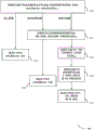
Fig. 3 illustrates an example of a slot (7 OFDM symbols) for a downlink narrowband assignment with a single antenna port, along with relative EPRE values for resource elements of different OFDM symbols of a wireless resource for narrowband wireless communication, in accordance with various aspects of the present disclosure. In some cases, time slot 300 may represent an aspect of a communication by a UE115 or a base station 105 as described with reference to fig. 1-2. In this example, slot 300 is an example of an in-band NB communication and has 12 frequency tones and spans seven OFDM symbols. In the example slot 300, the CRS 330 may be transmitted in the first and fifth symbols, and the NB-RS 315 may be transmitted in the sixth and seventh symbols.
For intra-band NB transmission, there may be four power offsets based on the presence or absence of NB-RS and CRS within an OFDM symbol. First ratio ρ NA305 may be the ratio of N-PDSCH EPRE 310 to NB-RS EPRE 315 within an OFDM symbol that contains neither legacy CRS nor NB-RS (i.e., symbols 2, 3, and 4 in the example of slot 300). Second ratio ρ B320 may be the ratio of N-PDSCH EPRE 325 to CRS EPRE 330 within an OFDM symbol containing CRS (i.e., symbols 1 and 5 in the example of slot 300). Third ratio ρ C335 may be a ratio of NB-RS EPRE 315 to CRS EPRE 330. The fourth ratio 340 may be based on p NA305、ρ B320 and ρ C335, and may be the ratio of N-PDSCH EPRE345 to NB-RS EPRE 315 within an OFDM symbol containing NB-RS. In some examples, for NB transmission, similar to legacy LTE, OFDM symbols that do not contain CRS (e.g., symbols 2, 3, 6, and 7 within a slot of slot 300) have equal power within the NB transmission. Thus, all power offsets between EPREs of different REs may be by configuring three relative powers ρNA305、ρ B320 and ρ C335.
In some examples, one or more of the power offsets may be based on the number of antenna ports for NB transmission. In some examples, the first ratio ρNAThe value of 305 or the fourth ratio 340 may be determined as a first value for NB transmissions with a single antenna port and a second value for NB transmissions with two antenna ports. Additionally or alternatively, the number of antenna ports and ρ may be basedNA305 to determine a fourth ratio 340 of N-PDSCH EPRE345 to NB-RS EPRE 315 within an OFDM symbol containing NB-RS. In some examples, the values may be according to Max (0,1.5 ρ) for two antenna portsNA0.5), and Max (0,1.2 ρ for a single antenna portNA0.2) to determine the fourth ratio 340.
In some examples, a base station may signal p to an NB-IoT UE NA305 and ρ B320, e.g., by providing a signal that can be used to determine ρ NA305 and ρ B320. In some examples, the base station may provide the first parameter PNASaid P isNAMay be UE-specific parameters and signaled to the UE through RRC signaling. In some examples, PNAMay be equal to p NA305. The base station may additionally or alternatively provide the second parameter PBSaid P isBMay be cell-specific parameters that may be signaled by the base station in system information (e.g., in SIB 2). In some examples, ρBMay be equal to pAPBIn which P isBIs determined based on the number of antenna ports for NB transmissions in the time slot 300. In some examples, ρCMay be configured by the base station and may be provided explicitly, e.g., through RRC signaling, or in a DL grant. In some examples, ρCMay be implicitly determined, e.g., based on the CE level of the NB UE. For example, the UE may assume, for normal coverage, N-PDSs within each OFDM symbol containing NB-RSsThe fourth ratio 340 of CH EPRE to NB-RS EPRE is 0dB and the fourth ratio 340 is assumed to be-3 dB for extended coverage. In some examples, a UE may be configured with a plurality of different fourth ratios that will be implicitly determined based on the CE level associated with the UE.
Although the time slot 300 of fig. 3 shows an example within a band, similar power ratios may be used in guard band deployments and standalone deployments. In a guard band deployment, CRS transmissions will not be present in NB RBs, but may be present during a particular symbol in the adjacent wideband system bandwidth, which may result in the EPRE for the NB transmission during that symbol being adjusted to comply with the power limit associated with that particular symbol. In some examples, to determine the relative power adjustments used in different REs of an NB transmission, the base station may provide two power offsets, i.e., ρNAAnd ρBAs defined above with respect to the in-band deployment. As mentioned above, although NB transmissions in a guard band deployment may not have CRS transmissions, to determine the power borrowed from an in-band RB in an OFDM symbol containing CRS in the wideband system bandwidth, a UE may still need to know ρB. Similar to the examples in the frequency band discussed above, for ρNAAnd ρBMay be determined by comparing the parameter P to a guard band ratioAAnd PBIs configured for NB UEs that can use the PAAnd PBTo determine pNAAnd ρB. Further, similar to the in-band deployment example discussed above, the ratio of N-PDSCH EPRE to NB-RS EPRE within an OFDM symbol containing NB-RSs may be based on the number of antenna ports. In some examples, the ratio may be determined as a first value for a single antenna port and a second value for two antenna ports. Additionally or alternatively, may depend on the number of antenna ports and pNAThe ratio is determined. In some examples, the values may be according to Max (0,1.5 ρ) for two antenna portsNA-0.5) and Max (0,1.2 ρ for a single antenna portNA0.2) to determine the ratio of N-PDSCH EPRE to NB-RS EPRE within an OFDM symbol containing NB-RS.
In some examples, an independent deployment may have NB transmissions with one power ratio that may need to be identified. The one power ratio may be pNAThe p is similar to that indicated aboveNAMay be the ratio of N-PDSCH EPRE to NB-RS EPRE within OFDM symbols that contain neither NB-RS nor legacy CRS (i.e., symbols 2, 3, and 4 within the slot). In some examples, ρNAMay be configured using similar methods as discussed above for in-band and guard band deployments (e.g., ρNAMay depend on the number of antenna ports). Further, similar to the in-band and guard-band deployment examples discussed above, the ratio of N-PDSCH EPRE to NB-RS EPRE within an OFDM symbol containing NB-RS may be based on the number of antenna ports, and may be in accordance with Max (0,1.5 ρ) for two antenna portsNA-0.5) and Max (0,1.2 ρ for a single antenna portNA-0.2).
The UE receives signaling corresponding to power adjustment as discussed above and uses the relative power of the different REs to provide enhanced demodulation of the received NB transmissions. In some examples, knowledge of different power ratios may allow NB UEs to enhance channel estimation, e.g., by allowing UEs to perform channel estimation based on both CRS and NB-RS. Additionally or alternatively, different power ratios may allow the UE to improve LLR calculations across different OFDM symbols.
Fig. 4 illustrates an example of a method 400 for downlink power adjustment in narrowband wireless communications, in accordance with various aspects of the disclosure. In some cases, the method 400 may represent aspects of a technique performed by a UE115 or a base station 105 as described with reference to fig. 1-2. The method 400 may be performed by a wireless device (e.g., a UE or a base station as discussed above with respect to fig. 1-3).
At block 405, the wireless device may identify p as a ratio of N-PDSCH EPRE to NB-RS EPRE within an OFDM symbol that contains neither legacy CRS nor NB-RSNA. For example, the base station may identify ρ based on a configured power for the NB-RS and an available power for OFDM symbols that contain neither legacy CRS nor NB-RSNA. The base station may signal ρ to the UENAAssociated parameters, the UE may identify p based at least in part on the signaled parametersNA. In some examples, the signaled parameter may be a ratio ρNA. In other examples, the signaled parameter may relate to ρ through a defined relationship that may be configured at the UENAAnd (4) correlating.
The wireless device may perform other operations based on the type of deployment used for NB communication. If the wireless device is performing NB communication in a standalone deployment, at block 410, the device may base the identified ρNAThe ratio to determine N-PDSCH EPRE and NB-RS EPRE. For example, the device may identify N-PDSCH EPRE, and based on the identified pNARatio to determine NB-RS EPRE. Similarly, the device may identify the NB-RS EPRE and based on the identified ρNAThe ratio to determine N-PDSCH EPRE. In some examples, the UE may determine the received power on the OFDM symbol and may be based on the identified ρNARatios to determine NB-RS EPRE and N-PDSCH EPRE.
In an example of a wireless device operating in a guard band deployment, at block 415, the device may identify ρ as a ratio of N-PDSCH EPRE to CRS EPRE within an OFDM symbol containing legacy CRSB. For example, the base station may identify ρ based on the configured power for CRS and the available power for OFDM symbols containing CRSB. The base station may signal ρ to the UEBAssociated parameters, the UE may identify p based at least in part on the signaled parametersB. In some examples, the signaled parameter is a value of: when it is related to the ratio ρNAMultiplication provides rhoB。
At block 420, a wireless device operating in a guard band deployment may be based on the identified ρNAAnd ρBThe ratio to determine N-PDSCH EPRE and NB-RS EPRE. For example, the device may be based on ρNAAnd ρBTo identify N-PDSCH EPRE for CRS-containing OFDM symbols in adjacent wideband system bandwidths, and to identify N-PDSCH EPRE for CRS-containing OFDM symbols in adjacent wideband system bandwidthsN-PDSCH EPRE of the OFDM symbol containing the NB-RS, and may identify the NB-RS EPRE.
If the wireless device is performing NB communication in an in-band deployment, the device may perform the operations of block 415 as discussed above to identify ρB. At block 425, the device may identify ρ as a ratio of NB-RS EPRE to CRS EPREC。ρCThe value of (c) may be identified and signaled as discussed above with respect to fig. 3, or may be given by a default value (e.g., 0dB) if not identified in the signaling. At block 430, a device operating in an in-band deployment may identify a ratio of N-PDSCH EPRE to NB-RS EPRE within an OFDM symbol containing an NB-RS. Such identification may be based on explicit signaling or implicit determination (e.g., based on CE level or number of antenna ports), as discussed above with respect to fig. 3. At block 435, the device may base on ρNA、ρBAnd ρCTo determine N-PDSCH EPRE, CRS EPRE and NB-RS EPRE, as discussed above with respect to fig. 3.
Fig. 5 illustrates an example of a process flow 500 for downlink power adjustment in narrowband wireless communications in accordance with various aspects of the disclosure. Process flow 500 may include a base station 105-b and a UE 115-b, which base station 105-b and UE 115-b may be examples of corresponding devices described with reference to fig. 1-2.
At block 505, the base station 105-b may identify a reference to p in a manner similar to that discussed aboveNA、ρBAnd ρCThe power ratio of (a). In an example where base station 105-b and UE 115-b are deployed within a frequency band, base station 105-b may identify each of the ratios for UE 115-b. In the example of a base station 105-b and a UE 115-b in a guard band deployment, the base station 105-b may identify p for the UE 115-bNAAnd ρB. In an example where the base station 105-b and the UE 115-b are in separate deployments, the base station 105-b may identify p for the UE 115-bNA。
At block 510, the base station 105-b may identify a cell-specific parameter for the power ratio. Such cell-specific parameters may include: for example, within an OFDM symbol that may be used to determine the inclusion of CRSParameter of the ratio of N-PDSCH EPRE to CRS EPRE. The base station 105-b may identify the cell-specific parameters in a manner as discussed above, e.g., by identifying parameters that may be used to determine ρNAMay be used to determine pBThe second parameter of (1). In some examples, it may be identified that may be used to determine ρCBut in some examples, pCMay be determined implicitly as similarly discussed above (e.g., based on a default value, based on a number of antenna ports, based on a CE level, etc.).
The base station 105-b may send the cell-specific parameters in the SIB transmission 515. In some examples, the cell-specific parameters may be sent to multiple different UEs in a SIB2 transmission.
At block 520, the base station 105-b may identify a UE-specific parameter for the power ratio. Such UE-specific parameters may include: for example, parameters may be used to determine the ratio of N-PDSCH EPRE to NB-RS EPRE within an OFDM symbol that contains neither NB-RS nor legacy CRS. The base station 105-b may send the UE-specific parameters in an RRC transmission 525.
At block 530, the UE 115-b may identify an EPRE ratio and an EPRE value based at least in part on the parameters signaled in the SIB transmission 515 and the RRC transmission 525. The identification of the EPRE ratio and EPRE values may be performed in accordance with techniques as discussed above with respect to fig. 2-4. In some examples, the UE 115-b may assume a power ratio in the absence of active signaling from the base station 105-b. For example, the UE 115-b may determine the EPRE ratio based on the number of antenna ports. If the number of NB-RS antenna ports is one, the UE 115-b may assume that the NB-RS EPRE and the EPRE for all NB DL channels are the same. In another example, if the number of NB-RS antenna ports is two, the UE 115-b assumes that the NB-RS EPRE per antenna port is 3dB greater than the EPRE per antenna port for all NB DL channels.
The base station 105-b may transmit a DL grant 535 and the UE 115-b may receive the DL grant 535. DL grant 535 may include information related to downlink resources for an NB transmission to be received at UE 115-b, and DL grant 535 may be followed by DL transmission 540. The DL transmission may be an NB transmission of an RB occupying one of the DL resources.
At block 545, the UE 115-b may determine N-PDSCH EPRE and NB-RS EPRE based on the number of antenna ports, EPRE ratio, coverage enhancement level, measured NB-RS level, or any combination thereof, similar to that discussed above with respect to fig. 2-4. In some examples, as discussed above, the UE 115-b may determine certain EPRE values and EPRE ratios based on the deployment of the UE 115-b and the base station 105-b (e.g., based on independent, in-band, or guard band deployments).
At block 550, the UE 115-b may demodulate the DL transmission using a demodulation technique that may be enhanced by the determined EPRE and EPRE ratio. In some examples, UE 115-b may perform channel estimation based on the relative EPRE values and may compute LLRs associated with one or more received REs based on the one or more EPRE values. The channel estimates and LLR determinations may be used to demodulate and decode DL transmission 540.
Fig. 6 illustrates a block diagram of a wireless device 600 that supports downlink power adjustment in narrowband wireless communications, in accordance with various aspects of the disclosure. The wireless device 600 may be an example of aspects of the UE115 described with reference to fig. 1, 2, and 5. Wireless device 600 may include a receiver 605, a transmitter 610, and a UE DL power adjustment manager 615. Wireless device 600 may also include a processor. Each of these components may communicate with each other.
UE DL power adjustment manager 615 may receive signal 612, which signal 612 may be a representation of signal 607 and may include NB-RS, CRS, or NB DL channels. The UE DL power adjustment manager 615 may identify a number of antenna ports for narrowband transmissions and identify a first power ratio between the first EPRE and the NB-RS EPRE based at least in part on the number of antenna ports. The first EPRE may be an EPRE for two or more OFDM symbols that contain neither NB-RS nor CRS. The UE DL power adjustment manager 615 may also identify a first EPRE or NB-RS EPRE based on the first power ratio. The UE DL power adjustment manager 615 may demodulate at least a portion of the N-PDSCH transmissions received in two or more OFDM symbols based on the identification. In some cases, the UE DL power adjustment manager 615 may communicate information 617 to the transmitter 610. The UE DL power adjustment manager 615 may also be an example of aspects of the UE DL power adjustment manager 905 described with reference to fig. 9.
Fig. 7 illustrates a block diagram of a wireless device 700 that supports downlink power adjustment in narrowband wireless communications, in accordance with various aspects of the disclosure. The wireless device 700 may be an example of aspects of the wireless device 600 or UE115 as described with reference to fig. 1, 2, and 5-6. Wireless device 700 may include a receiver 705, a UE DL power adjustment manager 710, and a transmitter 730. The wireless device 700 may also include a processor. Each of these components may communicate with each other.
The UE DL power adjustment manager 710 may be an example of aspects of the UE DL power adjustment manager 615 described with reference to fig. 6. The UE DL power adjustment manager 710 may include a demodulation component 715, an EPRE identification component 720, and a power ratio component 725. The UE DL power adjustment manager 710 may be an example of aspects of the UE DL power adjustment manager 905 described with reference to fig. 9.
The power ratio component 725 may identify factors for determining one or more power ratios for NB transmissions. For example, the power ratio component 725 may identify cell-specific or UE-specific parameters transmitted in the signal 712 from the base station. In some examples, power ratio component 725 may identify a number of antenna ports for NB transmission. The power ratio component 725 may determine one or more power ratios for NB transmissions based on the parameters and/or the number of antenna ports. For example, a first power ratio between an EPRE for two or more OFDM symbols in which CRS and NB-RS are absent, and an NB-RS EPRE may be determined. In certain examples, power ratio component 725 may identify a second power ratio between the CRS EPRE and a second EPRE for REs containing downlink shared channel transmissions within OFDM symbols that include the CRS. In some examples, power ratio component 725 may identify a third power ratio between the NB-RS EPRE and the CRS EPRE, and may determine a fourth power ratio between the NB-RS EPRE and the third EPRE for REs containing downlink shared channel transmissions within OFDM symbols including the NB-RS based on the first power ratio, the second power ratio, the third power ratio, or any combination thereof. In some examples, the power ratio component 725 may communicate the identified power ratio 740 to the EPRE identification component 720.
A demodulation component 715 may receive the signaling 712 and demodulate at least a portion of the N-PDSCH transmission received in two or more OFDM symbols based on the identified power ratio and relative EPRE value 742. In some cases, demodulation component 715 may perform channel estimation based on the relative EPRE values and may compute LLRs associated with one or more received REs based on one or more EPRE values. In some examples, demodulation component 715 may transmit demodulated symbols 744 (e.g., LLRs, etc.) of the N-PDSCH transmission to other components (e.g., decoders, etc.) within wireless device 700 for further processing. Demodulation component 715 may transmit the channel estimate to transmitter 730 via signal 717 for channel feedback.
Fig. 8 illustrates a block diagram of a UE DL power adjustment manager 800 (which may be an example of corresponding components of wireless device 600 or wireless device 700) in accordance with various aspects of the disclosure. That is, the UE DL power adjustment manager 800 may be an example of aspects of the UE DL power adjustment manager 615 or the UE DL power adjustment manager 710 described with reference to fig. 6 and 7. The UE DL power adjustment manager 800 may also be an example of aspects of the UE DL power adjustment manager 905 described with reference to fig. 9.
UE DL power adjustment manager 800 may include RRC component 805, antenna port component 810, demodulation component 815, EPRE identification component 820, power ratio component 825, CE level component 830, and SIB component 835. Each of these modules may communicate with each other directly or indirectly (e.g., via one or more buses).
The SIB component 835 may identify SIB communications from the base station 105. In some examples, SIB component 835 may receive the second power parameter in SIB communication 803. SIB component 835 can receive first ratio 807 from RRC component 805. In some cases, identifying the second power ratio includes: the second power parameter is received in SIB communication 803 and the second power ratio is determined based on the second power parameter and the first power ratio 807. RRC component 805 can communicate second power ratio 850 to power ratio component 825.
The CE level component 830 can determine a CE level for communication. In some cases, CE level component 830 may determine the third power ratio based on the configured CE level. In some examples, the CE level component 830 may communicate the third power ratio 852 to the power ratio component 825.
The power ratio component 825 can receive the first power ratio and/or the first power parameter 840 from the RRC component 805. In some examples, power ratio component 825 may receive number of antenna ports 842 from antenna port component 810. In some examples, power ratio component 825 may receive second power ratio 850 from SIB component 835. In some examples, the power ratio component 825 may receive the third power ratio 852 from the CE level component 830. The power ratio component 825 may determine the first power ratio based on the first power parameter 840, and in some examples, based on additional parameters (e.g., the number of antenna ports 842). In some cases, power ratio component 825 may identify one or more of the other power ratios as discussed herein. In some examples, the power ratio component 825 may communicate the identified power ratio 860 to the EPRE identification component 820.
A demodulation component 815 can receive signaling 814 (e.g., from receiver 605 or 705) and demodulate at least a portion of the N-PDSCH transmission received in the signaling 814. For example, demodulation component 815 may demodulate two or more OFDM symbols in the N-PDSCH transmission based on the identified power ratio and relative EPRE value 862. In some cases, demodulating at least a portion of the N-PDSCH transmission may include: channel estimation is performed based on the relative EPREs, and LLR calculations for one or more received REs are performed based on the one or more EPREs. In some examples, demodulation component 815 may transmit demodulated symbols 844 (e.g., LLRs, etc.) of the N-PDSCH transmission to other components (e.g., decoders, etc.) within wireless device 800 for further processing.
Fig. 9 illustrates a diagram of a system 900 that includes an apparatus that supports downlink power adjustment in narrowband wireless communications, in accordance with various aspects of the disclosure. For example, system 900 may include UE115-c, which UE115-c may be an example of wireless device 600, wireless device 700, or UE115 as described with reference to fig. 1, 2, and 5-8.
The UE115-c may include a UE DL power adjustment manager 905, a memory 910, a processor 920, a transceiver 925, an antenna 930, and an ECC module 935. Each of these modules may communicate with each other directly or indirectly (e.g., via one or more buses). The UE DL power adjustment manager 905 may be an example of a UE DL power adjustment manager as described with reference to fig. 6 to 8.
The memory 910 may include Random Access Memory (RAM) and Read Only Memory (ROM). Memory 910 may store computer-readable, computer-executable software comprising instructions that, when executed, cause a processor to perform various functions described herein (e.g., downlink power adjustment in narrowband wireless communications, etc.). In some cases, the software 915 may not be directly executable by the processor, but may cause the computer (e.g., when compiled and executed) to perform functions described herein. Processor 920 may include intelligent hardware devices (e.g., Central Processing Unit (CPU), microcontroller, Application Specific Integrated Circuit (ASIC), etc.).
The transceiver 925 may communicate bi-directionally with one or more networks via one or more antennas, wired or wireless links, as described above. For example, the transceiver 925 may be in bidirectional communication with a base station 105 or a UE 115. The transceiver 925 may also include a modem to modulate packets and provide the modulated packets to an antenna for transmission and to demodulate packets received from the antenna. In some cases, the wireless device may include a single antenna 930. However, in some cases, a device may have more than one antenna 930, the antennas 930 being capable of concurrently transmitting or receiving multiple wireless transmissions.
The ECC module 935 may enable operations using ECCs, such as communications using shared or unlicensed spectrum, using reduced TTI or subframe durations, or using a large number of component carriers.
Fig. 10 illustrates a block diagram of a wireless device 1000 that supports downlink power adjustment in narrowband wireless communications, in accordance with various aspects of the disclosure. The wireless device 1000 may be an example of aspects of the base station 105 described with reference to fig. 1 and 2. Wireless device 1000 may include a receiver 1005, a base station DL power adjustment manager 1010, and a transmitter 1015. The wireless device 1000 may also include a processor. Each of these components may communicate with each other.
Base station DL power adjustment manager 1010 may receive signal 1012, which signal 1012 may be representative of signal 1007. The base station DL power adjustment manager 1010 may identify a first N-PDSCH EPRE for two or more OFDM symbols in which CRS and NB-RS are not present, identify a first power ratio between the first N-PDSCH EPRE and NB-RS EPRE, and signal the first power ratio to one or more receivers. The base station DL power adjustment manager 1010 may transmit a signal 1017 to the transmitter 1015, the signal 1017 indicating the first N-PDSCH EPRE and a first power ratio between the first N-PDSCH EPRE and the NB-RS EPRE. The base station DL power adjustment manager 1010 may also be an example of aspects of the base station DL power adjustment manager 1305 described with reference to fig. 13.
The transmitter 1015 may transmit signals 1022 received from other components of the wireless device 1000. A signal 1022 including a first power ratio between the first N-PDSCH EPRE and the NB-RS EPRE may be transmitted to the other device. In some examples, the transmitter 1015 may be collocated with a receiver in a transceiver module. For example, the transmitter 1015 may be an example of aspects of the transceiver 1325 described with reference to fig. 13. The transmitter 1015 may include a single antenna, or it may include multiple antennas.
Fig. 11 illustrates a block diagram of a wireless device 1100 that supports downlink power adjustment in narrowband wireless communications, in accordance with various aspects of the disclosure. The wireless device 1100 may be an example of aspects of the wireless device 1000 or the base station 105 described with reference to fig. 1, 2, 5, and 10. Wireless device 1100 may include a receiver 1105, a base station DL power adjustment manager 1110, and a transmitter 1130. Wireless device 1100 may also include a processor. Each of these components may communicate with each other.
Base station DL power adjustment manager 1110 may be an example of aspects of base station DL power adjustment manager 1010 described with reference to fig. 10. The base station DL power adjustment manager 1110 may include an EPRE component 1115, a power ratio component 1120, and a power ratio signaling component 1125. Base station DL power adjustment manager 1110 may be an example of aspects of base station DL power adjustment manager 1305 described with reference to fig. 13.
The EPRE identification component 1115 may identify a first N-PDSCH EPRE for two or more OFDM symbols in which CRS and NB-RS are not present. The EPRE identification component 1115 may communicate EPRE 1140 (e.g., N-PDSCH EPRE) to the power ratio component 1120.
The power ratio component 1120 may receive EPRE 1140 from the EPRE component 1115. Power ratio component 1120 may identify a first power ratio between the first N-PDSCH EPRE and the NB-RS EPRE, identify a second power ratio between the CRS EPRE and the second EPRE for REs containing N-PDSCH transmissions within OFDM symbols that include CRS, identify a third power ratio between the NB-RS EPRE and the CRS EPRE, and determine a fourth power ratio between the NB-RS EPRE and the third EPRE for REs containing N-PDSCH transmissions within OFDM symbols that include NB-RS based on the first power ratio, the second power ratio, the third power ratio, or any combination thereof. In some examples, power ratio component 1120 may apply a power ratio to an NB transmission signal to be transmitted via transmitter 1130 in accordance with the received EPRE 1140. In some examples, the power ratio component 1120 may transmit the identified power ratio 1142 to the power ratio signaling component 1125.
The power ratio signaling component 1125 may receive the identified power ratio 1142 from the power ratio component 1120. The power ratio signaling component 1125 may signal a first power ratio to one or more receivers, a second power ratio to one or more receivers, and a third power ratio to one or more receivers. The power ratio signaling component 1125 may transmit a power ratio applied to a transmission signal to one or more receivers. The power ratio signaling component 1125 may transmit the signal 1117 to the transmitter 1130. In some examples, signal 1117 may include one or more power ratios for signaling to one or more receivers.
The transmitter 1130 may transmit signals 1122 received from other components of the wireless device 1100. For example, base station DL power adjustment manager 1110 can communicate information 1117 to transmitter 1130. In some examples, the transmitter 1130 may be collocated with a receiver in a transceiver module. For example, the transmitter 1130 may be an example of aspects of the transceiver 1325 described with reference to fig. 13. The transmitter 1130 may utilize a single antenna, or it may utilize multiple antennas.
Fig. 12 illustrates a block diagram of a base station DL power adjustment manager 1200 (which may be an example of corresponding components of wireless device 1000 or wireless device 1100) in accordance with various aspects of the disclosure. That is, base station DL power adjustment manager 1200 may be an example of aspects of base station DL power adjustment manager 1010 or base station DL power adjustment manager 1110 described with reference to fig. 10 and 11. The base station DL power adjustment manager 1200 may also be an example of aspects of the base station DL power adjustment manager 1305 described with reference to fig. 13.
The base station DL power adjustment manager 1200 may include an RRC component 1205, an EPRE component 1210, a power ratio component 1215, and a power ratio signaling component 1220. Each of these modules may communicate with each other directly or indirectly (e.g., via one or more buses).
The EPRE identifying component 1210 may identify a first N-PDSCH EPRE for two or more OFDM symbols in which CRS and NB-RS are not present. The EPRE identification component 1210 may transmit the EPRE 1240 to the power ratio component 1215.
The power ratio component 1215 may receive the EPRE 1240 from the EPRE component 1210. The power ratio component 1215 may identify a first power ratio between the first N-PDSCH EPRE and the NB-RS EPRE, identify a second power ratio between the CRS EPRE and the second EPRE for REs containing N-PDSCH transmissions within OFDM symbols that include CRS, identify a third power ratio between the NB-RS EPRE and the CRS EPRE, and determine a fourth power ratio between the NB-RS EPRE and the third EPRE for REs containing N-PDSCH transmissions within OFDM symbols that include NB-RS based on the first power ratio, the second power ratio, the third power ratio, or any combination thereof. The power ratio component 1215 may communicate a power ratio 1242 to the power ratio component 1215.
The RRC component 1205 can receive the power ratio 1242 from the power ratio component 1215. RRC component 1205 can manage RRC communications. In some cases, signaling the first power ratio includes: a first parameter associated with a first power ratio is included in RRC signaling sent to one or more receivers. RRC component 1205 may communicate a first parameter associated with the first power ratio included in RRC signaling 1250 to power ratio signaling component 1220.
The power ratio signaling component 1220 may signal a first power ratio to one or more receivers, a second power ratio to one or more receivers, or a third power ratio to one or more receivers. In some cases, signaling the power ratio may include: one or more parameters associated with the power ratio are signaled in a SIB or RRC transmission to one or more receivers. In some examples, power ratio signaling component 1220 may communicate signal 1217 to a transmitter. In some examples, signal 1217 may include one or more power ratios to be signaled.
Fig. 13 illustrates a diagram of a wireless system 1300 that includes an apparatus that supports downlink power adjustment in narrowband wireless communications, in accordance with various aspects of the disclosure. For example, system 1300 may include base station 105-d, which base station 105-d may be an example of wireless device 1000, wireless device 1100, or base station 105 as described with reference to fig. 1, 2, and 10-12. The base station 105-d may also include components for two-way voice and data communications, including components for transmitting communications and components for receiving communications. For example, a base station 105-d may be in bidirectional communication with one or more UEs 115.
The base station 105-d may include a base station DL power adjustment manager 1305, memory 1310, processor 1320, transceiver 1325, antenna 1330, base station communications module 1335, and network communications module 1340. Each of these modules may communicate with each other directly or indirectly (e.g., via one or more buses). The base station DL power adjustment manager 1305 may be an example of a base station DL power adjustment manager as described with reference to fig. 10 to 12.
The transceiver 1325 may communicate bi-directionally with one or more networks via one or more antennas, wired or wireless links, as described above. For example, the transceiver 1325 may communicate bi-directionally with the base station 105 or the UE 115. The transceiver 1325 can also include a modem to modulate packets and provide the modulated packets to the antenna for transmission and to demodulate packets received from the antenna. In some cases, the wireless device may include a single antenna 1330. However, in some cases, a device may have more than one antenna 930, the antennas 930 being capable of concurrently transmitting or receiving multiple wireless transmissions.
The base station communication module 1335 may manage communications with other base stations 105 and may include a controller or scheduler for controlling communications with UEs 115 in cooperation with other base stations 105. For example, the base station communication module 1335 may coordinate scheduling for transmissions to the UE115 for various interference mitigation techniques, such as beamforming or joint transmission. In some examples, the base station communication module-95 may provide an X2 interface within LTE/LTE-a wireless communication network technology to provide communication between base stations 105.
The network communication module 1340 may manage communication with a core network (e.g., via one or more wired backhaul links). For example, the network communication module 1340 may manage the transmission of data communications for client devices (e.g., one or more UEs 115).
Fig. 14 shows a flow diagram illustrating a method 1400 for downlink power adjustment in narrowband wireless communications, in accordance with various aspects of the disclosure. The operations of method 1400 may be implemented by a device (e.g., UE115 or a component thereof) as described with reference to fig. 1 and 2. For example, the operations of method 1400 may be performed by a UE DL power adjustment manager as described herein. In some examples, the UE115 may execute a set of codes to control the functional elements of the device to perform the functions described below. Additionally or alternatively, the UE115 may perform aspects of the functions described below using dedicated hardware.
At block 1405, the UE115 may identify a first power ratio between a first EPRE and an NB-RS EPRE, wherein the first EPRE is forFor two or more OFDM symbols in which CRS and NB-RS are not present, as described above with reference to fig. 2 to 5. In some examples, the first power ratio between the first EPRE and the NB-RS EPRE may be based on a number of antenna ports. In some examples, the UE115 may receive the first power parameter in RRC signaling and determine the first power ratio based at least in part on the first power parameter. In some examples, the operations of block 1405 may be performed by a power ratio component as described with reference to fig. 7 and 8. In some examples, the UE115 may identify p as a ratio of N-PDSCH EPRE to NB-RS EPRE within an OFDM symbol that contains neither legacy CRS nor NB-RSNA. In some examples, the base station may signal ρ to the UENAAssociated parameters, the UE may identify p based at least in part on the signaled parametersNA. In some examples, the signaled parameter may be a ratio ρNA. In other examples, the signaled parameter may relate to ρ through a defined relationship that may be configured at the UENAAnd (4) correlating.
At block 1410, the UE115 may identify one from the group consisting of the first EPRE and the NB-RS EPRE based on the first power ratio, as described above with reference to fig. 2-5. In some examples, the UE115 may identify the first EPRE based on the first power ratio. In some examples, the operations of block 1410 may be performed by an EPRE identification component as described with reference to fig. 7 and 8. In some examples, the UE115 may be based on the identified ρNAThe ratio to determine N-PDSCH EPRE and NB-RS EPRE. For example, the UE115 may identify N-PDSCH EPRE and based on the identified pNARatio to determine NB-RS EPRE. Similarly, the UE115 may identify NB-RS EPRE and based on the identified ρNAThe ratio to determine N-PDSCH EPRE. In some examples, the UE115 may determine the received power on the OFDM symbol and may be based on the identified ρNARatios to determine NB-RS EPRE and N-PDSCH EPRE.
At optional block 1415, UE115 may identify a second power ratio between N-PDSCH EPRE and CRS EPRE for an OFDM symbol containing CRS, as described above with reference to fig. 2-5. In thatIn an example where UE115 operates in a guard band deployment, UE115 may identify ρ as a ratio of N-PDSCH EPRE to CRS EPRE within an OFDM symbol containing legacy CRSB. In some examples, the base station 105 may identify ρ based on the configured power for CRS and the available power for OFDM symbols containing CRSB. The base station 105 may signal ρ to the UE115BAssociated parameters, the UE115 may identify p based at least in part on the signaled parametersB。
In some examples, the UE115 may identify a third power ratio between the NB-RS EPRE and the CRS EPRE. In some examples, the UE115 may receive the third power ratio. In some examples, the UE115 may determine the third power ratio based at least in part on the configured coverage enhancement level. In some examples, the UE115 may determine a fourth power ratio between the NB-RS EPRE and the third EPRE for resource elements containing downlink shared channel transmissions within OFDM symbols including the NB-RS based at least in part on the first power ratio, the second power ratio, the third power ratio, or any combination thereof. In some examples, the operations of block 1415 may be performed by a power ratio component as described with reference to fig. 7 and 8. In some examples, the UE115 may identify ρ as a ratio of NB-RS EPRE to CRS EPREC。ρCMay be identified and signaled as discussed above with respect to fig. 3. In some examples, a UE115 operating in an in-band deployment may identify a fourth ratio of N-PDSCH EPRE to NB-RS EPRE within an OFDM symbol containing NB-RS. In some examples, such identification may be based on explicit signaling or implicit determination (e.g., based on CE level), as discussed above with respect to fig. 3 and 4.
At optional block 1420, the UE115 may identify a CRS EPRE based at least in part on one or more other power ratios, as described above with reference to fig. 2-5. In some examples, the operations of block 1420 may be performed by an EPRE identification component as described with reference to fig. 7 and 8. In some examples, the UE115 may be based on pNA、ρBAnd ρCTo determine N-PDSCH EPRE, CRS EPRE and NB-RS EPRE, as described above with respect to FIG. 3 and4, discussed above.
At block 1425, the UE115 may demodulate at least a portion of the downlink shared channel transmission received in two or more OFDM symbols based on the identifying, as described above with reference to fig. 2-5. In some examples, the UE115 may demodulate at least a portion of the downlink shared channel transmission received in the two or more OFDM symbols based at least in part on the identification of the first EPRE. In some examples, the operations of block 1425 may be performed by a demodulation component as described with reference to fig. 7 and 8. In some examples, a UE receiving signaling corresponding to one or more power adjustments may use the relative power of different REs to provide enhanced demodulation of received NB transmissions.
Fig. 15 shows a flow diagram illustrating a method 1500 for downlink power adjustment in narrowband wireless communications, in accordance with various aspects of the present disclosure. The operations of method 1500 may be implemented by an apparatus (e.g., base station 105 or a component thereof) as described with reference to fig. 1 and 2. For example, the operations of method 1500 may be performed by a base station DL power adjustment manager as described herein. In some examples, the base station 105 may execute sets of codes to control the functional elements of the device to perform the functions described below. Additionally or alternatively, the base station 105 may use dedicated hardware to perform aspects of the functions described below.
At block 1505, the base station 105 may identify a first downlink shared channel, EPRE, for two or more OFDM symbols in which CRS and NB-RS are not present, as described above with reference to fig. 2-5. In some examples, the operations of block 1505 may be performed by an EPRE component as described with reference to fig. 11 and 12.
At block 1510, the base station 105 may identify a first power ratio between the first downlink shared channel EPRE and the NB-RS EPRE, as described above with reference to fig. 2-5. In some examples, the base station 105 may identify the first power ratio based on a number of antenna ports used for NB DL transmissions. In some examples, the base station 105 may include a first parameter associated with a first power ratio in RRC signaling sent to one or more receivers. At a certain pointIn some examples, the operations of block 1510 may be performed by a power ratio component as described with reference to fig. 11 and 12. In some examples, base station 105 may identify ρ based on a configured power for NB-RS and an available power for OFDM symbols that contain neither legacy CRS nor NB-RSNA. The base station may signal ρ to the UENAAssociated parameters, the UE may identify p based at least in part on the signaled parametersNA. In some examples, the signaled parameter may be a ratio ρNA. In other examples, the signaled parameter may relate to ρ through a defined relationship that may be configured at the UENAAnd (4) correlating.
At an optional block 1515, the base station 105 may identify a CRS EPRE for an OFDM symbol in which the CRS is present, as described above with reference to fig. 2-5. In some examples, the operations of block 1515 may be performed by an EPRE component as described with reference to fig. 11 and 12.
At optional block 1520, the base station 105 may identify a second power ratio between the first N-PDSCH EPRE and the CRS EPRE, as described above with reference to fig. 2-5. In an example, the base station 105 may identify ρ based on the configured power for CRS and the available power for OFDM symbols containing CRSB. The base station 105 may signal ρ to the UE115BAssociated parameters, the UE115 may identify p based at least in part on the signaled parametersB。
In some examples, the base station 105 may identify a third power ratio between the NB-RS EPRE and the CRS EPRE. In some examples, the base station 105 may signal the third power ratio to one or more receivers. In some examples, the base station 105 may signal the third power ratio to the UE 115. In some examples, the base station 105 may determine a fourth power ratio between the NB-RS EPRE and the third EPRE for resource elements containing downlink shared channel transmissions within OFDM symbols including the NB-RS based at least in part on the first power ratio, the second power ratio, the third power ratio, or any combination thereof. In some examples, the operations of block 1520 may be performed by a power ratio component as described with reference to fig. 11 and 12.
At block 1525, the base station 105 may signal the first power ratio to one or more receivers, as described above with reference to fig. 2-5. In some examples, the base station 105 may include a second parameter associated with a second power ratio in a SIB transmitted to the one or more receivers. In some examples, the operations of block 1525 may be performed by a power ratio signaling component as described with reference to fig. 11 and 12. In some examples, the base station may provide the second parameter PBSaid P isBMay be cell-specific parameters that may be signaled by the base station at the SIB. In some examples, ρBMay be equal to pAPBIn which P isBIs determined based on the number of antenna ports.
At optional block 1530, the base station 105 may signal the second power ratio to one or more receivers, as described above with reference to fig. 2-5. In some examples, the operations of block 1525 may be performed by a power ratio signaling component as described with reference to fig. 11 and 12.
It should be noted that the methods describe possible implementations and that the operations and steps may be rearranged or otherwise modified such that other implementations are possible. In some examples, aspects from two or more of the methods may be combined. For example, aspects of each of the methods may include steps or aspects of the other methods, or other steps or techniques described herein. Accordingly, aspects of the present disclosure may provide for downlink power adjustment in narrowband wireless communications.
The description herein is provided to enable any person skilled in the art to make or use the present disclosure. Various modifications to the disclosure will be readily apparent to those skilled in the art, and the generic principles defined herein may be applied to other variations without departing from the scope of the disclosure. Thus, the disclosure is not intended to be limited to the examples and designs described herein but is to be accorded the widest scope consistent with the principles and novel features disclosed herein.
The functions described herein may be implemented in hardware, software executed by a processor, firmware, or any combination thereof. If implemented in software executed by a processor, the functions may be stored on or transmitted over as one or more instructions or code on a computer-readable medium. Other examples and implementations are within the scope and spirit of the present disclosure and appended claims. For example, due to the nature of software, the functions described above may be implemented using software executed by a processor, hardware, firmware, hard wiring, or a combination of any of these. Features that perform a function may be physically located at various locations, including being distributed such that some of the function is performed at different physical locations. As used herein (including in the claims), when the term "and/or" is used in a list having two or more items, it means that any one of the listed items may be employed by itself, or any combination of two or more of the listed items may be employed. For example, if a composition is described as containing component A, B and/or C, the composition may contain: a alone; b alone; c alone; a combination of A and B; a combination of A and C; a combination of B and C; or a combination of A, B and C. Further, as used herein (including in the claims), a "or" as used in a list of items (e.g., a list of items prefaced by a phrase such as "at least one of" or "one or more of") indicates an inclusive list such that, for example, a phrase referring to at least one of the list of items refers to any combination of those items, including a single member. By way of example, "A, B or at least one of C" is intended to cover A, B, C, A-B, A-C, B-C and A-B-C, as well as any combination of multiples of the same element (e.g., any other ordering of A-AA-A-A, A-A-B, A-A-C, A-B-B, A-C-C, B-B, B-B-B, B-B-C, C-C and C-C-C or A, B and C). As used herein, the phrase "based on" should not be construed as a reference to a closed set of conditions. For example, an exemplary step described as "based on condition a" may be based on both condition a and condition B without departing from the scope of the present disclosure. In other words, as used herein, the phrase "based on" should be interpreted in the same manner as the phrase "based at least in part on" is interpreted.
Computer-readable media includes both non-transitory computer storage media and communication media including any medium that facilitates transfer of a computer program from one place to another. A non-transitory storage medium may be any available medium that can be accessed by a general purpose or special purpose computer. By way of example, and not limitation, non-transitory computer-readable media can comprise RAM, ROM, electrically erasable programmable read-only memory (EEPROM), Compact Disk (CD) ROM or other optical disk storage, magnetic disk storage or other magnetic storage devices, or any other non-transitory medium that can be used to carry or store desired program code means in the form of instructions or data structures and that can be accessed by a general-purpose or special-purpose computer or a general-purpose or special-purpose processor. Also, any connection is properly termed a computer-readable medium. For example, if the software is transmitted from a website, server, or other remote source using a coaxial cable, fiber optic cable, twisted pair, Digital Subscriber Line (DSL), or wireless technologies such as infrared, radio, and microwave, then the coaxial cable, fiber optic cable, twisted pair, DSL, or wireless technologies such as infrared, radio, and microwave are included in the definition of medium. Disk and disc, as used herein, includes CD, laser disc, optical disc, Digital Versatile Disc (DVD), floppy disk and blu-ray disc where disks usually reproduce data magnetically, while discs reproduce data optically with lasers. Combinations of the above are also included within the scope of computer-readable media.
The techniques described herein may be used for various wireless communication systems such as CDMA, TDMA, FDMA, OFDMA, single-carrier frequency division multiple access (SC-FDMA), and other systems. The terms "system" and "network" are often used interchangeably. A CDMA system may implement a radio technology such as CDMA2000, Universal Terrestrial Radio Access (UTRA), and so on. CDMA2000 covers IS-2000, IS-95 and IS-856 standards. IS-2000 releases 0 and A may be referred to generally as CDMA 20001X, 1X, etc. IS-856(TIA-856) IS commonly referred to as CDMA 20001 xEV-DO, High Rate Packet Data (HRPD), etc. UTRA includes wideband CDMA (wcdma) and other variants of CDMA. TDMA systems may implement wireless technologies such as global system for mobile communications (GSM). The OFDMA system may implement wireless technologies such as Ultra Mobile Broadband (UMB), evolved UTRA (E-UTRA), IEEE802.11, IEEE 802.16(WiMAX), IEEE 802.20, flash OFDM, etc. UTRA and E-UTRA are part of the Universal Mobile Telecommunications System (UMTS). 3GPP LTE and LTE-advanced (LTE-A) are new versions of UMTS that use E-UTRA. UTRA, E-UTRA, UMTS, LTE-a, and GSM are described in documents from an organization entitled "third Generation partnership project" (3 GPP). CDMA2000 and UMB are described in documents from an organization named "third generation partnership project 2" (3GPP 2). The techniques described herein may be used for the systems and wireless techniques mentioned above, as well as other systems and wireless techniques. Although the description describes an LTE system for purposes of example, and LTE terminology is used in much of the description above, the techniques are applicable beyond LTE applications.
In LTE/LTE-a networks (including the networks described herein), the term eNB may be used generally to describe a base station. One or more wireless communication systems described herein may include heterogeneous LTE/LTE-a networks, where different types of enbs provide coverage for various geographic areas. For example, each eNB or base station may provide communication coverage for a macro cell, a small cell, or other type of cell. The term "cell" may be used to describe a base station, a carrier or Component Carrier (CC) associated with a base station, or a coverage area (e.g., sector, etc.) of a carrier or base station, depending on the context.
A base station may include, or may be referred to by those skilled in the art as, a base transceiver station, a wireless base station, an Access Point (AP), a wireless transceiver, a node B, an evolved node B (enb), a home node B, a home evolved node B, or some other suitable terminology. The geographic coverage area for a base station can be divided into sectors that form only a portion of the coverage area. One or more wireless communication systems described herein may include different types of base stations (e.g., macro cell base stations or small cell base stations). The UEs described herein are capable of communicating with various types of base stations and network devices, including macro enbs, small cell enbs, relay base stations, and the like. For different technologies, there may be overlapping geographic coverage areas. In some cases, different coverage areas may be associated with different communication technologies. In some cases, the coverage area for one communication technology may overlap with a coverage area associated with another technology. Different technologies may be associated with the same base station or with different base stations.
A macro cell typically covers a relatively large geographic area (e.g., several kilometers in radius) and may allow unrestricted access by UEs with service subscriptions with the network provider. A small cell is a lower power base station than a macro cell, which may operate in the same or different (e.g., licensed, unlicensed, etc.) frequency band as the macro cell. According to various examples, the small cells may include pico cells, femto cells, and micro cells. For example, a pico cell may cover a small geographic area and may allow unrestricted access by UEs with service subscriptions with the network provider. A femto cell may also cover a small geographic area (e.g., a home) and may provide restricted access by UEs having an association with the femto cell (e.g., UEs in a Closed Subscriber Group (CSG), UEs for users in the home, etc.). An eNB for a macro cell may be referred to as a macro eNB. An eNB for a small cell may be referred to as a small cell eNB, pico eNB, femto eNB, or home eNB. An eNB may support one or more (e.g., two, three, four, etc.) cells (e.g., CCs). The UE is capable of communicating with various types of base stations and network devices, including macro enbs, small cell enbs, relay base stations, and the like.
One or more of the wireless communication systems described herein may support synchronous or asynchronous operation. For synchronous operation, the base stations may have similar frame timing, and transmissions from different base stations may be approximately aligned in time. For asynchronous operation, the base stations may have different frame timing, and transmissions from different base stations may not be aligned in time. The techniques described herein may be used for synchronous operations or asynchronous operations.
The DL transmissions described herein may also be referred to as forward link transmissions, while the UL transmissions may also be referred to as reverse link transmissions. Each of the communication links described herein (including, for example, the wireless communication systems 100 and 200 of fig. 1 and 2) may include one or more carriers, where each carrier may be a signal made up of multiple subcarriers (e.g., waveform signals of different frequencies). Each modulated signal may be transmitted on a different subcarrier and may carry control information (e.g., reference signals, control channels, etc.), overhead information, user data, and so on. It is described herein that a communication link (e.g., communication link 125 of fig. 1) may transmit bi-directional communications using Frequency Division Duplex (FDD) operation (e.g., using paired spectrum resources) or TDD operation (e.g., using unpaired spectrum resources). A frame structure for FDD (e.g., frame structure type 1) and a frame structure for TDD (e.g., frame structure type 2) may be defined.
Accordingly, aspects of the present disclosure may provide for downlink power adjustment in narrowband wireless communications. It should be noted that the methods describe possible implementations and that the operations and steps may be rearranged or otherwise modified such that other implementations are possible. In some examples, aspects from two or more of the methods may be combined.
The various illustrative blocks and modules described in connection with the disclosure herein may be implemented or performed with a general purpose processor, a Digital Signal Processor (DSP), an ASIC, a Field Programmable Gate Array (FPGA) or other programmable logic device, discrete gate or transistor logic, discrete hardware components, or any combination thereof designed to perform the functions described herein. A general purpose processor may be a microprocessor, but in the alternative, the processor may be any conventional processor, controller, microcontroller, or state machine. A processor may also be implemented as a combination of computing devices (e.g., a combination of a DSP and a microprocessor, a plurality of microprocessors, one or more microprocessors in conjunction with a DSP core, or any other such configuration). Thus, the functions described herein may be performed by one or more other processing units (or cores), on at least one Integrated Circuit (IC). In various examples, different types of ICs (e.g., structured/platform ASICs, FPGAs, or other semi-custom ICs) may be used that may be programmed in any manner known in the art. The functions of each unit may also be implemented, in whole or in part, with instructions embodied in a memory, formatted to be executed by one or more general or special purpose processors.
Claims (60)
1. A method at a wireless device for wireless communication, comprising:
identifying a number of antenna ports for narrowband transmission over a narrowband downlink shared channel;
identifying a first ratio between an Energy Per Resource Element (EPRE) of downlink shared channel resources of the narrowband downlink shared channel and an EPRE of a narrowband reference signal (NB-RS) based at least in part on the number of antenna ports;
identifying that the narrowband downlink shared channel is configured in accordance with an in-band deployment within a wideband downlink shared channel;
identifying a second ratio between an EPRE of the NB-RS and an EPRE of a cell-specific reference signal (CRS) of the wideband downlink shared channel based at least in part on identifying that the narrowband downlink shared channel is configured pursuant to the in-band deployment; and
demodulate the downlink shared channel resources based at least in part on the first ratio and the second ratio, wherein the narrowband downlink shared channel comprises the NB-RS and a CRS of the wideband downlink shared channel.
2. The method of claim 1, wherein identifying the first ratio comprises:
identifying a first value of the first ratio, or
Identifying a second value of the first ratio in a case that the number of antenna ports is two.
3. The method of claim 1, further comprising:
identifying a third ratio between an EPRE of the CRS and a second EPRE comprising resource elements of a narrowband transmission within an orthogonal frequency division multiplexing, OFDM, symbol comprising the CRS; and
identifying one of the EPRE or the second EPRE of the CRS based at least in part on the third ratio.
4. The method of claim 1, wherein identifying the second ratio comprises:
determining the second ratio based at least in part on the configured coverage enhancement level, or
Implicitly determining the second ratio based on a default value.
5. The method of claim 1, wherein identifying the second ratio comprises receiving the second ratio.
6. The method of claim 3, further comprising:
determining a fourth ratio between the EPRE of the NB-RS and a third EPRE within an OFDM symbol comprising resource elements of a narrowband transmission based at least in part on the first ratio, the second ratio, the third ratio, or any combination thereof, the OFDM symbol comprising the NB-RS.
7. The method of claim 6, wherein demodulating the downlink shared channel resources comprises:
performing channel estimation based at least in part on the EPRE of the CRS, the EPRE of the NB-RS, the EPRE of the downlink shared channel resource, the second EPRE, the third EPRE, or any combination thereof; and
calculating a log-likelihood ratio (LLR) associated with one or more received resource elements based at least in part on the EPRE of the CRS, the EPRE of the NB-RS, the EPRE of the downlink shared channel resource, the second EPRE, the third EPRE, or any combination thereof.
8. The method of claim 3, wherein identifying the third ratio comprises:
receiving parameters in a System Information Block (SIB); and
determining the third ratio based at least in part on the parameter and the first ratio.
9. The method of claim 1, wherein identifying the first ratio comprises:
receiving a parameter in Radio Resource Control (RRC) signaling; and
determining the first ratio based at least in part on the parameter.
10. The method of claim 9, further comprising:
determining the first ratio based at least in part on the parameter and the number of antenna ports.
11. A method at a wireless device for wireless communication, comprising:
identifying a number of antenna ports for narrowband transmission over a narrowband downlink shared channel;
identifying a first ratio between an Energy Per Resource Element (EPRE) of downlink shared channel resources of the narrowband downlink shared channel and an EPRE of a narrowband reference signal (NB-RS) based at least in part on the number of antenna ports;
identifying that the narrowband downlink shared channel is configured in accordance with an in-band deployment within a wideband downlink shared channel;
identifying a second ratio between an EPRE of the NB-RS and an EPRE of a cell-specific reference signal (CRS) of the wideband downlink shared channel based at least in part on identifying that the narrowband downlink shared channel is configured pursuant to the in-band deployment;
signaling the second ratio to one or more receivers; and
transmitting the narrowband transmission to the one or more receivers according to the identified EPRE of the downlink shared channel resources and the second ratio, wherein the narrowband downlink shared channel comprises the NB-RS and a CRS of the wideband downlink shared channel.
12. The method of claim 11, further comprising:
identifying a third ratio between an EPRE of the CRS and a second EPRE comprising resource elements of a narrowband transmission within an orthogonal frequency division multiplexing, OFDM, symbol comprising the CRS; and
signaling the third ratio to the one or more receivers,
wherein the transmitting the narrowband transmission to the one or more receivers comprises transmitting the CRS and the resource elements according to the third ratio.
13. The method of claim 12, wherein signaling the third ratio comprises:
include a parameter associated with the third ratio in a System Information Block (SIB) transmitted to the one or more receivers.
14. The method of claim 12, further comprising:
determining a fourth ratio between the EPRE of the NB-RS and a third EPRE comprising resource elements of a narrowband transmission within an OFDM symbol based at least in part on the first ratio, wherein the OFDM comprises the NB-RS.
15. The method of claim 11, wherein signaling the first ratio comprises:
include a parameter associated with the first ratio in Radio Resource Control (RRC) signaling sent to the one or more receivers.
16. An apparatus for wireless communication, comprising:
means for identifying a number of antenna ports for narrowband transmission over a narrowband downlink shared channel;
means for identifying a first ratio between an Energy Per Resource Element (EPRE) of downlink shared channel resources of the narrowband downlink shared channel and an EPRE of a narrowband reference signal (NB-RS) based at least in part on the number of antenna ports;
means for identifying that the narrowband downlink shared channel is configured in accordance with an in-band deployment within a wideband downlink shared channel;
means for identifying a second ratio between an EPRE of the NB-RS and an EPRE of a cell-specific reference signal (CRS) of the wideband downlink shared channel based at least in part on identifying that the narrowband downlink shared channel is configured pursuant to the in-band deployment;
means for demodulating the downlink shared channel resources based at least in part on the first ratio and the second ratio, wherein the narrowband downlink shared channel comprises the NB-RS and a CRS of the wideband downlink shared channel.
17. The apparatus of claim 16, wherein means for identifying the first ratio comprises:
means for identifying a first value of the first ratio if the number of antenna ports is one, or
Means for identifying a second value of the first ratio if the number of antenna ports is two.
18. The apparatus of claim 16, further comprising:
means for identifying a third ratio between an EPRE of the CRS and a second EPRE comprising resource elements of a narrowband transmission within an orthogonal frequency division multiplexing, OFDM, symbol, wherein the OFDM symbol comprises the CRS; and
means for identifying one of an EPRE or the second EPRE of the CRS based at least in part on the third ratio.
19. The apparatus of claim 16, wherein means for identifying the second ratio comprises:
means for determining the second ratio based at least in part on the configured coverage enhancement level, or
Means for implicitly determining the second ratio based on a default value.
20. The apparatus of claim 16, wherein means for identifying the second ratio comprises means for receiving the second ratio.
21. The apparatus of claim 18, further comprising:
means for determining a fourth ratio between the EPRE of the NB-RS and a third EPRE within an OFDM symbol comprising resource elements of a narrowband transmission based at least in part on the first ratio, the second ratio, the third ratio, or any combination thereof, the OFDM symbol comprising the NB-RS.
22. The apparatus of claim 21, wherein means for demodulating the downlink shared channel resource comprises:
means for performing channel estimation based at least in part on the EPRE of the CRS, the EPRE of the NB-RS, the EPRE of the downlink shared channel resource, the second EPRE, the third EPRE, or any combination thereof; and
means for calculating a log-likelihood ratio (LLR) associated with one or more received resource elements based at least in part on the EPRE of the CRS, the EPRE of the NB-RS, the EPRE of the downlink shared channel resource, the second EPRE, the third EPRE, or any combination thereof.
23. The apparatus of claim 18, wherein means for identifying the third ratio comprises:
means for receiving parameters in a System Information Block (SIB); and
means for determining the third ratio based at least in part on the parameter and the first ratio.
24. The apparatus of claim 16, wherein means for identifying the first ratio comprises:
means for receiving a parameter in Radio Resource Control (RRC) signaling; and
means for determining the first ratio based at least in part on the parameter.
25. The apparatus of claim 24, further comprising:
means for determining the first ratio based at least in part on the parameter and the number of antenna ports.
26. An apparatus for wireless communication, comprising:
means for identifying a number of antenna ports for narrowband transmission over a narrowband downlink shared channel;
means for identifying a first ratio between an Energy Per Resource Element (EPRE) of downlink shared channel resources of the narrowband downlink shared channel and an EPRE of a narrowband reference signal (NB-RS) based at least in part on the number of antenna ports;
means for identifying that the narrowband downlink shared channel is configured in accordance with an in-band deployment of a wideband downlink shared channel;
means for identifying a second ratio between an EPRE of the NB-RS and an EPRE of a cell-specific reference signal, CRS, of the wideband downlink shared channel based at least in part on the narrowband downlink shared channel being configured pursuant to the in-band deployment;
means for signaling the second ratio to one or more receivers; and
means for transmitting the narrowband transmission to the one or more receivers according to the EPRE of the identified downlink shared channel resources and the second ratio, wherein the narrowband downlink shared channel comprises the NB-RS and a CRS of the wideband downlink shared channel.
27. The apparatus of claim 26, further comprising:
means for identifying a third ratio between the EPRE of the CRS and an EPRE comprising resource elements of a narrowband transmission within an orthogonal frequency division multiplexing, OFDM, symbol comprising the CRS; and
means for signaling the third ratio to the one or more receivers,
wherein the means for transmitting the narrowband transmission to the one or more receivers transmits the CRS and the resource elements according to the third ratio.
28. The apparatus of claim 27, wherein means for signaling the third ratio comprises:
means for including a parameter associated with the third ratio in a System Information Block (SIB) transmitted to the one or more receivers.
29. The apparatus of claim 28, further comprising:
means for determining a fourth ratio between the EPRE of the NB-RS and an EPRE of resource elements comprising a narrowband transmission within an OFDM symbol based at least in part on the first ratio, wherein the OFDM symbol comprises the NB-RS.
30. The apparatus of claim 26, wherein means for signaling the first ratio comprises:
means for including a parameter associated with the first ratio in radio resource control, RRC, signaling sent to the one or more receivers.
31. An apparatus for wireless communication, comprising:
a processor; and
a memory in electronic communication with the processor, wherein the processor is configured to cause the apparatus to:
identifying a number of antenna ports for narrowband transmission over a narrowband downlink shared channel;
identifying a first ratio between an Energy Per Resource Element (EPRE) of downlink shared channel resources of the narrowband downlink shared channel and an EPRE of a narrowband reference signal (NB-RS) based at least in part on the number of antenna ports;
identifying that the narrowband downlink shared channel is configured in accordance with an in-band deployment within a wideband downlink shared channel;
identifying a second ratio between an EPRE of the NB-RS and an EPRE of a cell-specific reference signal (CRS) of the wideband downlink shared channel based at least in part on identifying that the narrowband downlink shared channel is configured pursuant to the in-band deployment; and
demodulate the downlink shared channel resources based at least in part on the first ratio and the second ratio, wherein the narrowband downlink shared channel comprises the NB-RS and a CRS of the wideband downlink shared channel.
32. The apparatus of claim 31, wherein the processor is configured to cause the apparatus to:
identifying a first value of the first ratio, or
Identifying a second value of the first ratio in a case that the number of antenna ports is two.
33. The apparatus of claim 31, wherein the processor is configured to cause the apparatus to:
identifying a third ratio between an EPRE of the CRS and a second EPRE comprising resource elements of a narrowband transmission within an orthogonal frequency division multiplexing, OFDM, symbol comprising the CRS; and
identifying one of the CRS EPRE or the second EPRE based at least in part on the third ratio.
34. The apparatus of claim 31, wherein the processor is configured to cause the apparatus to receive the second ratio.
35. The apparatus of claim 33, the processor configured to cause the apparatus to:
determining a fourth ratio between the EPRE of the NB-RS and a third EPRE within an OFDM symbol comprising resource elements of a narrowband transmission based at least in part on the first ratio, the second ratio, the third ratio, or any combination thereof, the OFDM symbol comprising the NB-RS.
36. The apparatus of claim 35, wherein the processor is configured to cause the apparatus to:
performing channel estimation based at least in part on the EPRE of the CRS, the EPRE of the NB-RS, the EPRE of the downlink shared channel resource, the second EPRE, the third EPRE, or any combination thereof; and
calculating a log-likelihood ratio (LLR) associated with one or more received resource elements based at least in part on the EPRE of the CRS, the EPRE of the NB-RS, the EPRE of the downlink shared channel resource, the second EPRE, the third EPRE, or any combination thereof.
37. The apparatus of claim 33, wherein the processor is configured to cause the apparatus to:
receiving parameters in a System Information Block (SIB); and
determining the third ratio based at least in part on the parameter and the first ratio.
38. The apparatus of claim 31, wherein the processor is configured to cause the apparatus to:
receiving a parameter in Radio Resource Control (RRC) signaling; and
determining the first ratio based at least in part on the parameter.
39. The apparatus of claim 38, wherein the processor is configured to cause the apparatus to:
determining the first ratio based at least in part on the parameter and the number of antenna ports.
40. The apparatus of claim 31, wherein the processor is configured to cause the apparatus to:
determining the second ratio based at least in part on the configured coverage enhancement level, or
Implicitly determining the second ratio based on a default value.
41. An apparatus for wireless communication, comprising:
a processor; and
a memory in electronic communication with the processor, wherein the processor is configured to cause the apparatus to:
identifying a number of antenna ports for narrowband transmission over a narrowband downlink shared channel;
identifying a first ratio between an Energy Per Resource Element (EPRE) of downlink shared channel resources of the narrowband downlink shared channel and an EPRE of a narrowband reference signal (NB-RS) based at least in part on the number of antenna ports;
identifying that the narrowband downlink shared channel is configured in accordance with an in-band deployment within a wideband downlink shared channel;
identifying a second ratio between an EPRE of the NB-RS and an EPRE of a cell-specific reference signal (CRS) of the wideband downlink shared channel based at least in part on identifying that the narrowband downlink shared channel is configured pursuant to the in-band deployment;
signaling the second ratio to one or more receivers; and
transmitting the narrowband transmission to the one or more receivers according to the identified EPRE of the downlink shared channel resources and the second ratio, wherein the narrowband downlink shared channel comprises the NB-RS and a CRS of the wideband downlink shared channel.
42. The apparatus of claim 41, wherein the processor is configured to cause the apparatus to:
identifying a third ratio between an EPRE of the CRS and a second EPRE comprising resource elements of a narrowband transmission within an orthogonal frequency division multiplexing, OFDM, symbol comprising the CRS; and
signaling the third ratio to the one or more receivers,
transmitting the CRS and the resource elements according to the third ratio.
43. The apparatus of claim 42, wherein the processor is configured to cause the apparatus to:
include a parameter associated with the third ratio in a System Information Block (SIB) transmitted to the one or more receivers.
44. The apparatus of claim 42, further comprising:
determining a fourth ratio between the EPRE of the NB-RS and a third EPRE comprising resource elements of a narrowband transmission within an OFDM symbol based at least in part on the first ratio, wherein the OFDM comprises the NB-RS.
45. The device of claim 41, wherein signaling the first ratio comprises:
include a parameter associated with the first ratio in Radio Resource Control (RRC) signaling sent to the one or more receivers.
46. A non-transitory computer-readable medium storing code for performing wireless communications by a wireless device, the code comprising instructions executable by a processor to:
identifying a number of antenna ports for narrowband transmission over a narrowband downlink shared channel;
identifying a first ratio between an Energy Per Resource Element (EPRE) of downlink shared channel resources of the narrowband downlink shared channel and an EPRE of a narrowband reference signal (NB-RS) based at least in part on the number of antenna ports;
identifying that the narrowband downlink shared channel is configured in accordance with an in-band deployment within a wideband downlink shared channel;
identifying a second ratio between an EPRE of the NB-RS and an EPRE of a cell-specific reference signal (CRS) of the wideband downlink shared channel based at least in part on identifying that the narrowband downlink shared channel is configured pursuant to the in-band deployment; and
demodulate the downlink shared channel resources based at least in part on the first ratio and the second ratio, wherein the narrowband downlink shared channel comprises the NB-RS and a CRS of the wideband downlink shared channel.
47. The non-transitory computer readable medium of claim 46, wherein the instructions executable by the processor to identify the first ratio comprise instructions executable by the processor to:
identifying a first value of the first ratio, or
Identifying a second value of the first ratio in a case that the number of antenna ports is two.
48. The non-transitory computer readable medium of claim 46, wherein the instructions are further executable by the processor to:
identifying a third ratio between an EPRE of the CRS and a second EPRE comprising resource elements of a narrowband transmission within an orthogonal frequency division multiplexing, OFDM, symbol comprising the CRS; and
identifying one of the EPRE or the second EPRE of the CRS based at least in part on the third ratio.
49. The non-transitory computer readable medium of claim 46, wherein the instructions executable by the processor to identify the second ratio comprise instructions executable by the processor to receive the second ratio.
50. The non-transitory computer readable medium of claim 48, wherein the instructions are further executable by the processor to:
determining a fourth ratio between the EPRE of the NB-RS and a third EPRE within an OFDM symbol comprising resource elements of a narrowband transmission based at least in part on the first ratio, the second ratio, the third ratio, or any combination thereof, the OFDM symbol comprising the NB-RS.
51. The non-transitory computer-readable medium of claim 50, wherein the instructions executable by the processor to demodulate the downlink shared channel resources comprise instructions executable by the processor to:
performing channel estimation based at least in part on the EPRE of the CRS, the EPRE of the NB-RS, the EPRE of the downlink shared channel resource, the second EPRE, the third EPRE, or any combination thereof; and
calculating a log-likelihood ratio (LLR) associated with one or more received resource elements based at least in part on the EPRE of the CRS, the EPRE of the NB-RS, the EPRE of the downlink shared channel resource, the second EPRE, the third EPRE, or any combination thereof.
52. The non-transitory computer readable medium of claim 48, wherein the instructions executable by the processor to identify the third ratio comprise instructions executable by the processor to:
receiving parameters in a System Information Block (SIB); and
determining the third ratio based at least in part on the parameter and the first ratio.
53. The non-transitory computer readable medium of claim 46, wherein the instructions executable by the processor to identify the first ratio comprise instructions executable by the processor to:
receiving a parameter in Radio Resource Control (RRC) signaling; and
determining the first ratio based at least in part on the parameter.
54. The non-transitory computer readable medium of claim 53, wherein the instructions are further executable by the processor to:
determining the first ratio based at least in part on the parameter and the number of antenna ports.
55. The non-transitory computer readable medium of claim 46, wherein the instructions executable by the processor to identify the second ratio comprise instructions executable by the processor to:
determining the second ratio based at least in part on the configured coverage enhancement level, or
Implicitly determining the second ratio based on a default value.
56. A non-transitory computer-readable medium storing code for performing wireless communications by a wireless device, the code comprising instructions executable by a processor to:
identifying a number of antenna ports for narrowband transmission over a narrowband downlink shared channel;
identifying a first ratio between an Energy Per Resource Element (EPRE) of downlink shared channel resources of the narrowband downlink shared channel and an EPRE of a narrowband reference signal (NB-RS) based at least in part on the number of antenna ports;
identifying that the narrowband downlink shared channel is configured in accordance with an in-band deployment within a wideband downlink shared channel;
identifying a second ratio between an EPRE of the NB-RS and an EPRE of a cell-specific reference signal (CRS) of the wideband downlink shared channel based at least in part on identifying that the narrowband downlink shared channel is configured pursuant to the in-band deployment;
signaling the second ratio to one or more receivers; and
transmitting the narrowband transmission to the one or more receivers according to the identified EPRE of the downlink shared channel resources and the second ratio, wherein the narrowband downlink shared channel comprises the NB-RS and a CRS of the wideband downlink shared channel.
57. The non-transitory computer readable medium of claim 56, wherein the instructions are further executable by the processor to:
identifying a third ratio between an EPRE of the CRS and a second EPRE comprising resource elements of a narrowband transmission within an orthogonal frequency division multiplexing, OFDM, symbol comprising the CRS; and
signaling the third ratio to the one or more receivers,
transmitting the CRS and the resource elements according to the third ratio.
58. The non-transitory computer readable medium of claim 57, wherein the instructions executable by the processor to signal the third ratio comprise instructions executable by the processor to:
include a parameter associated with the third ratio in a System Information Block (SIB) transmitted to the one or more receivers.
59. The non-transitory computer readable medium of claim 57, wherein the instructions are further executable by the processor to:
determining a fourth ratio between the EPRE of the NB-RS and a third EPRE comprising resource elements of a narrowband transmission within an OFDM symbol based at least in part on the first ratio, wherein the OFDM comprises the NB-RS.
60. The non-transitory computer readable medium of claim 56, wherein the instructions executable by the processor to signal the first ratio comprise instructions executable by the processor to:
include a parameter associated with the first ratio in Radio Resource Control (RRC) signaling sent to the one or more receivers.
Applications Claiming Priority (5)
| Application Number | Priority Date | Filing Date | Title |
|---|---|---|---|
| US201662308581P | 2016-03-15 | 2016-03-15 | |
| US62/308,581 | 2016-03-15 | ||
| US15/447,914 US11057837B2 (en) | 2016-03-15 | 2017-03-02 | Downlink power adjustment in narrowband wireless communications |
| US15/447,914 | 2017-03-02 | ||
| PCT/US2017/020776 WO2017160513A1 (en) | 2016-03-15 | 2017-03-03 | Downlink power adjustment in narrowband wireless communications |
Publications (2)
| Publication Number | Publication Date |
|---|---|
| CN108781153A CN108781153A (en) | 2018-11-09 |
| CN108781153B true CN108781153B (en) | 2021-10-01 |
Family
ID=58361110
Family Applications (1)
| Application Number | Title | Priority Date | Filing Date |
|---|---|---|---|
| CN201780017079.0A Active CN108781153B (en) | 2016-03-15 | 2017-03-03 | Method and apparatus for communication |
Country Status (9)
| Country | Link |
|---|---|
| US (1) | US11057837B2 (en) |
| EP (1) | EP3430760B1 (en) |
| JP (1) | JP6961606B2 (en) |
| KR (1) | KR102319217B1 (en) |
| CN (1) | CN108781153B (en) |
| BR (1) | BR112018068505A2 (en) |
| ES (1) | ES2893325T3 (en) |
| RU (1) | RU2733210C2 (en) |
| WO (1) | WO2017160513A1 (en) |
Families Citing this family (16)
| Publication number | Priority date | Publication date | Assignee | Title |
|---|---|---|---|---|
| WO2018030682A1 (en) * | 2016-08-08 | 2018-02-15 | 엘지전자(주) | Method for transmitting reference signal in nb-iot system, and device therefor |
| WO2018208054A1 (en) * | 2017-05-06 | 2018-11-15 | 엘지전자 주식회사 | Method for d2d operation of terminal in wireless communication system and terminal using said method |
| US10560237B2 (en) * | 2017-05-30 | 2020-02-11 | Qualcomm Incorporated | Cell-specific reference signal transmissions for evolved machine type communication |
| CN111586825B (en) | 2017-08-09 | 2021-11-16 | 维沃移动通信有限公司 | Power control method, receiving method, power distribution method and related equipment |
| US11218350B2 (en) * | 2017-10-09 | 2022-01-04 | Qualcomm Incorporated | Downlink demodulation reference signal sharing for short transmission time intervals |
| CN107959517B (en) * | 2017-11-09 | 2020-08-25 | 武汉邮电科学研究院 | Wireless power clouding method and system based on large-scale antenna array |
| WO2019148433A1 (en) * | 2018-02-01 | 2019-08-08 | Qualcomm Incorporated | Enhanced four port narrowband reference signal (nrs) |
| CN110474698B (en) * | 2018-05-11 | 2022-03-01 | 中兴通讯股份有限公司 | Power ratio determination method and device |
| CN110708756B (en) * | 2018-07-09 | 2023-01-31 | 成都鼎桥通信技术有限公司 | Resource allocation method and equipment based on channel power |
| CN111224698B (en) | 2018-11-23 | 2021-03-26 | 上海朗帛通信技术有限公司 | Method and device used in user equipment and base station for wireless communication |
| WO2020199066A1 (en) * | 2019-03-30 | 2020-10-08 | 华为技术有限公司 | Power control method and related device |
| CN112153738A (en) * | 2019-06-26 | 2020-12-29 | 中国移动通信有限公司研究院 | Configuration method, configuration device, network side equipment and computer readable storage medium |
| US11632751B2 (en) * | 2020-01-31 | 2023-04-18 | Qualcomm Incorporated | Determining an energy per resource element for a symbol including a cell-specific reference signal |
| CN111901280A (en) * | 2020-02-20 | 2020-11-06 | 中兴通讯股份有限公司 | Modulation coding strategy, power configuration method, device, equipment and storage medium |
| WO2021253395A1 (en) * | 2020-06-19 | 2021-12-23 | Lenovo (Beijing) Limited | Downlink power allocation for nbiot |
| WO2022086426A1 (en) * | 2020-10-23 | 2022-04-28 | Telefonaktiebolaget Lm Ericsson (Publ) | Method and apparatus for downlink power allocation for 16 qam modulation scheme in nb-iot system |
Citations (1)
| Publication number | Priority date | Publication date | Assignee | Title |
|---|---|---|---|---|
| CN104025673A (en) * | 2012-01-03 | 2014-09-03 | Lg电子株式会社 | Method for setting downlink transmission power in wireless access system, and apparatus therefor |
Family Cites Families (23)
| Publication number | Priority date | Publication date | Assignee | Title |
|---|---|---|---|---|
| US7046694B2 (en) * | 1996-06-19 | 2006-05-16 | Digital Radio Express, Inc. | In-band on-channel digital broadcasting method and system |
| WO2008145800A1 (en) * | 2007-05-25 | 2008-12-04 | Nokia Corporation | Interference mitigation |
| US8238455B2 (en) | 2008-01-07 | 2012-08-07 | Samsung Electronics Co., Ltd. | Methods and apparatus for downlink PDSCH power setting |
| TW200947953A (en) * | 2008-05-15 | 2009-11-16 | Ralink Technology Corp | Method and apparatus for enhancing the efficiency of a wireless local area network |
| CN102111893B (en) * | 2009-12-23 | 2013-05-15 | 富士通株式会社 | Method and device for transmitting downlink scheduling singling |
| CN103262617B (en) | 2010-10-09 | 2016-05-04 | 中兴通讯股份有限公司 | The method of downlink power allocation |
| JP5383725B2 (en) * | 2011-02-10 | 2014-01-08 | シャープ株式会社 | Base station apparatus, mobile station apparatus, transmission method, reception method, and integrated circuit |
| CN103733560B (en) * | 2011-08-12 | 2017-08-11 | 交互数字专利控股公司 | Downlink resource allocations for flexible bandwidth operation in wireless system |
| GB2499222A (en) | 2012-02-08 | 2013-08-14 | Nec Corp | Generating a measurement report comprising information calculated from a power ratio of a non-zero power almost blank sub-frame |
| WO2013119052A1 (en) * | 2012-02-10 | 2013-08-15 | 엘지전자 주식회사 | Method for providing transmission power in wireless communication system and apparatus for same |
| WO2013122433A1 (en) * | 2012-02-17 | 2013-08-22 | Lg Electronics Inc. | Method and apparatus for transmitting and receiving signals in wireless communication system |
| US9407405B2 (en) * | 2012-04-06 | 2016-08-02 | Lg Electronics Inc. | Method of receiving downlink data and wireless device using the method |
| US9591646B2 (en) * | 2012-06-12 | 2017-03-07 | Qualcomm Incorporated | Reference signal power impact determination in new carrier type in LTE |
| US8890609B2 (en) * | 2012-11-20 | 2014-11-18 | Telefonaktiebolaget L M Ericsson (Publ) | Systems and methods for band-limited adaptation for PA linearization |
| US9306646B2 (en) * | 2013-01-02 | 2016-04-05 | Lg Electronics Inc. | Method and apparatus for receiving downlink radio signal |
| US10904039B2 (en) | 2013-03-29 | 2021-01-26 | Nec (China) Co., Ltd. | Methods and apparatuses for data transmission in a wireless communication system |
| US10404442B2 (en) * | 2013-07-02 | 2019-09-03 | Texas Instruments Incorporated | Inter-point parameter signaling in coordinated multi-point (CoMP) networks |
| GB201316165D0 (en) | 2013-09-11 | 2013-10-23 | Neul Ltd | Communication bandwidth |
| RU2573243C2 (en) * | 2013-10-28 | 2016-01-20 | Общество с ограниченной ответственностью "Топкон Позишионинг Системс" | Method and device for measuring current signal-to-noise ratio when decoding ldpc codes (versions) |
| KR20150107490A (en) * | 2014-03-14 | 2015-09-23 | 삼성전자주식회사 | Method and Device Transmitting Control Information for Interference Cancellation and Suppression in Wireless Communication Systems |
| US9571228B2 (en) | 2014-12-02 | 2017-02-14 | Cisco Technology, Inc. | Link adaptation based on neighboring cell transmission information |
| JP6599561B2 (en) * | 2015-12-18 | 2019-10-30 | テレフオンアクチーボラゲット エルエム エリクソン(パブル) | Narrowband sync signal transmission and reception |
| EP3414955B1 (en) * | 2016-03-14 | 2021-10-13 | Samsung Electronics Co., Ltd. | Method and apparatus for synchronization operation in cellular internet of things networks |
-
2017
- 2017-03-02 US US15/447,914 patent/US11057837B2/en active Active
- 2017-03-03 EP EP17712306.4A patent/EP3430760B1/en active Active
- 2017-03-03 KR KR1020187026617A patent/KR102319217B1/en active IP Right Grant
- 2017-03-03 ES ES17712306T patent/ES2893325T3/en active Active
- 2017-03-03 RU RU2018132449A patent/RU2733210C2/en active
- 2017-03-03 JP JP2018548197A patent/JP6961606B2/en active Active
- 2017-03-03 WO PCT/US2017/020776 patent/WO2017160513A1/en active Application Filing
- 2017-03-03 CN CN201780017079.0A patent/CN108781153B/en active Active
- 2017-03-03 BR BR112018068505A patent/BR112018068505A2/en unknown
Patent Citations (1)
| Publication number | Priority date | Publication date | Assignee | Title |
|---|---|---|---|---|
| CN104025673A (en) * | 2012-01-03 | 2014-09-03 | Lg电子株式会社 | Method for setting downlink transmission power in wireless access system, and apparatus therefor |
Also Published As
| Publication number | Publication date |
|---|---|
| EP3430760B1 (en) | 2021-09-01 |
| US11057837B2 (en) | 2021-07-06 |
| KR20180124044A (en) | 2018-11-20 |
| BR112018068505A2 (en) | 2019-01-22 |
| RU2018132449A3 (en) | 2020-07-23 |
| RU2733210C2 (en) | 2020-09-30 |
| KR102319217B1 (en) | 2021-10-28 |
| US20170273026A1 (en) | 2017-09-21 |
| WO2017160513A1 (en) | 2017-09-21 |
| EP3430760A1 (en) | 2019-01-23 |
| RU2018132449A (en) | 2020-04-15 |
| CN108781153A (en) | 2018-11-09 |
| ES2893325T3 (en) | 2022-02-08 |
| JP6961606B2 (en) | 2021-11-05 |
| JP2019510414A (en) | 2019-04-11 |
Similar Documents
| Publication | Publication Date | Title |
|---|---|---|
| CN108781153B (en) | Method and apparatus for communication | |
| CN107710666B (en) | Broadcast channel repetition | |
| EP3353938B1 (en) | Common synchronization channel design for narrowband communications | |
| KR102487565B1 (en) | System Information for Enhanced Machine Type Communication | |
| CN108541377B (en) | Narrowband related subframe availability for MTC | |
| CN107683579B (en) | Wireless communication method, system and device for use in contention-based spectrum | |
| EP3378183B1 (en) | Back-to-back reference signals | |
| EP3427453B1 (en) | Noise and interference estimation in wireless systems using multiple transmission time intervals | |
| JP2018532298A (en) | Downlink and synchronization techniques for narrowband wireless communication | |
| CN111988123A (en) | Method, apparatus, and computer readable medium for narrowband control channel decoding |
Legal Events
| Date | Code | Title | Description |
|---|---|---|---|
| PB01 | Publication | ||
| PB01 | Publication | ||
| SE01 | Entry into force of request for substantive examination | ||
| SE01 | Entry into force of request for substantive examination | ||
| GR01 | Patent grant | ||
| GR01 | Patent grant |