CN108780648B - Audio processing for time mismatched signals - Google Patents
Audio processing for time mismatched signals Download PDFInfo
- Publication number
- CN108780648B CN108780648B CN201780017113.4A CN201780017113A CN108780648B CN 108780648 B CN108780648 B CN 108780648B CN 201780017113 A CN201780017113 A CN 201780017113A CN 108780648 B CN108780648 B CN 108780648B
- Authority
- CN
- China
- Prior art keywords
- signal
- encoded
- value
- shift
- audio signal
- Prior art date
- Legal status (The legal status is an assumption and is not a legal conclusion. Google has not performed a legal analysis and makes no representation as to the accuracy of the status listed.)
- Active
Links
- 238000012545 processing Methods 0.000 title description 15
- 230000005236 sound signal Effects 0.000 claims abstract description 558
- 238000000034 method Methods 0.000 claims description 212
- 230000004044 response Effects 0.000 claims description 113
- 230000008859 change Effects 0.000 claims description 108
- 238000004891 communication Methods 0.000 claims description 18
- 230000007423 decrease Effects 0.000 claims description 7
- 238000010295 mobile communication Methods 0.000 claims description 4
- 229920001690 polydopamine Polymers 0.000 claims 1
- 230000000875 corresponding effect Effects 0.000 description 113
- 230000007774 longterm Effects 0.000 description 56
- 230000001364 causal effect Effects 0.000 description 49
- 238000012937 correction Methods 0.000 description 47
- 238000009499 grossing Methods 0.000 description 37
- 230000002123 temporal effect Effects 0.000 description 27
- 238000010586 diagram Methods 0.000 description 22
- 230000006870 function Effects 0.000 description 22
- 238000012952 Resampling Methods 0.000 description 21
- 230000003111 delayed effect Effects 0.000 description 17
- 230000007704 transition Effects 0.000 description 16
- 230000008569 process Effects 0.000 description 14
- 238000005070 sampling Methods 0.000 description 10
- 230000009977 dual effect Effects 0.000 description 7
- 230000000694 effects Effects 0.000 description 4
- 238000001914 filtration Methods 0.000 description 4
- 238000007781 pre-processing Methods 0.000 description 4
- 230000003595 spectral effect Effects 0.000 description 4
- 230000002596 correlated effect Effects 0.000 description 3
- 238000005314 correlation function Methods 0.000 description 3
- 230000003247 decreasing effect Effects 0.000 description 3
- 238000005516 engineering process Methods 0.000 description 3
- 238000012986 modification Methods 0.000 description 3
- 230000004048 modification Effects 0.000 description 3
- 238000013459 approach Methods 0.000 description 2
- 230000005284 excitation Effects 0.000 description 2
- 238000005457 optimization Methods 0.000 description 2
- 238000012546 transfer Methods 0.000 description 2
- 230000001131 transforming effect Effects 0.000 description 2
- 230000006978 adaptation Effects 0.000 description 1
- 230000003139 buffering effect Effects 0.000 description 1
- 239000000969 carrier Substances 0.000 description 1
- 230000001413 cellular effect Effects 0.000 description 1
- 230000003750 conditioning effect Effects 0.000 description 1
- 230000001934 delay Effects 0.000 description 1
- 230000001419 dependent effect Effects 0.000 description 1
- 238000013461 design Methods 0.000 description 1
- 238000001514 detection method Methods 0.000 description 1
- 238000013213 extrapolation Methods 0.000 description 1
- 238000009432 framing Methods 0.000 description 1
- 230000009467 reduction Effects 0.000 description 1
- 238000007670 refining Methods 0.000 description 1
- 230000001629 suppression Effects 0.000 description 1
- 230000001052 transient effect Effects 0.000 description 1
Images


Classifications
-
- G—PHYSICS
- G10—MUSICAL INSTRUMENTS; ACOUSTICS
- G10L—SPEECH ANALYSIS TECHNIQUES OR SPEECH SYNTHESIS; SPEECH RECOGNITION; SPEECH OR VOICE PROCESSING TECHNIQUES; SPEECH OR AUDIO CODING OR DECODING
- G10L19/00—Speech or audio signals analysis-synthesis techniques for redundancy reduction, e.g. in vocoders; Coding or decoding of speech or audio signals, using source filter models or psychoacoustic analysis
- G10L19/002—Dynamic bit allocation
-
- G—PHYSICS
- G10—MUSICAL INSTRUMENTS; ACOUSTICS
- G10L—SPEECH ANALYSIS TECHNIQUES OR SPEECH SYNTHESIS; SPEECH RECOGNITION; SPEECH OR VOICE PROCESSING TECHNIQUES; SPEECH OR AUDIO CODING OR DECODING
- G10L19/00—Speech or audio signals analysis-synthesis techniques for redundancy reduction, e.g. in vocoders; Coding or decoding of speech or audio signals, using source filter models or psychoacoustic analysis
- G10L19/008—Multichannel audio signal coding or decoding using interchannel correlation to reduce redundancy, e.g. joint-stereo, intensity-coding or matrixing
-
- G—PHYSICS
- G10—MUSICAL INSTRUMENTS; ACOUSTICS
- G10L—SPEECH ANALYSIS TECHNIQUES OR SPEECH SYNTHESIS; SPEECH RECOGNITION; SPEECH OR VOICE PROCESSING TECHNIQUES; SPEECH OR AUDIO CODING OR DECODING
- G10L19/00—Speech or audio signals analysis-synthesis techniques for redundancy reduction, e.g. in vocoders; Coding or decoding of speech or audio signals, using source filter models or psychoacoustic analysis
- G10L19/02—Speech or audio signals analysis-synthesis techniques for redundancy reduction, e.g. in vocoders; Coding or decoding of speech or audio signals, using source filter models or psychoacoustic analysis using spectral analysis, e.g. transform vocoders or subband vocoders
- G10L19/022—Blocking, i.e. grouping of samples in time; Choice of analysis windows; Overlap factoring
- G10L19/025—Detection of transients or attacks for time/frequency resolution switching
-
- G—PHYSICS
- G10—MUSICAL INSTRUMENTS; ACOUSTICS
- G10L—SPEECH ANALYSIS TECHNIQUES OR SPEECH SYNTHESIS; SPEECH RECOGNITION; SPEECH OR VOICE PROCESSING TECHNIQUES; SPEECH OR AUDIO CODING OR DECODING
- G10L19/00—Speech or audio signals analysis-synthesis techniques for redundancy reduction, e.g. in vocoders; Coding or decoding of speech or audio signals, using source filter models or psychoacoustic analysis
- G10L19/04—Speech or audio signals analysis-synthesis techniques for redundancy reduction, e.g. in vocoders; Coding or decoding of speech or audio signals, using source filter models or psychoacoustic analysis using predictive techniques
- G10L19/16—Vocoder architecture
- G10L19/18—Vocoders using multiple modes
- G10L19/22—Mode decision, i.e. based on audio signal content versus external parameters
Landscapes
- Engineering & Computer Science (AREA)
- Physics & Mathematics (AREA)
- Health & Medical Sciences (AREA)
- Signal Processing (AREA)
- Audiology, Speech & Language Pathology (AREA)
- Human Computer Interaction (AREA)
- Computational Linguistics (AREA)
- Acoustics & Sound (AREA)
- Multimedia (AREA)
- Mathematical Physics (AREA)
- Spectroscopy & Molecular Physics (AREA)
- Compression, Expansion, Code Conversion, And Decoders (AREA)
- Stereophonic System (AREA)
- Reduction Or Emphasis Of Bandwidth Of Signals (AREA)
Abstract
A device includes a processor and a transmitter. The processor is configured to determine a first mismatch value indicative of a first amount of time mismatch between a first audio signal and a second audio signal. The processor is also configured to determine a second mismatch value indicative of a second amount of time mismatch between the first audio signal and the second audio signal. The processor is further configured to determine a valid mismatch value based on the first mismatch value and the second mismatch value. The processor is also configured to generate at least one encoded signal having a bit allocation. The bit allocation is based at least in part on the valid mismatch value. The transmitter is configured to transmit the at least one encoded signal to a second device.
Description
Priority claiming
This application claims the priority benefits of the following commonly owned applications: U.S. provisional patent application No. 62/310,611, entitled "audio processing for time shifted signals (AUDIO PROCESSING FOR TEMPORALLY OFFSET SIGNALS)" filed on day 2016, 3, 18, and U.S. non-provisional patent application No. 15/461,356, entitled "audio processing for time mismatched signals (AUDIO PROCESSING FOR TEMPORALLY MISMATCHED SIGNALS)", filed on 2017, 3, 16, each of which is expressly incorporated herein by reference in their entirety.
Technical Field
The present invention relates generally to audio processing.
Background
Advances in technology have led to smaller and more powerful computing devices. For example, there are currently a variety of portable personal computing devices, including wireless telephones (e.g., mobile phones and smart phones), tablet computers, and laptop computers, which are small, lightweight, and easily carried by users. Such devices may communicate voice and data packets over wireless networks. In addition, many such devices incorporate additional functionality, such as digital cameras, digital video cameras, digital recorders, and audio file players. Moreover, such devices may process executable instructions including software applications, such as web browser applications, that may be used to access the internet. As such, such devices may include significant computing capabilities.
The computing device may include a plurality of microphones to receive the audio signal. In general, the sound source is closer to the first microphone than to the second microphone of the plurality of microphones. Thus, the second audio signal received from the second microphone may be delayed relative to the first audio signal received from the first microphone. In stereo encoding, an audio signal from a microphone may be encoded to generate a center channel signal and one or more side channel signals. The intermediate channel signal may correspond to a sum of the first audio signal and the second audio signal. The side channel signal may correspond to a difference between the first audio signal and the second audio signal. The first audio signal may not be aligned in time with the second audio signal due to a delay in receiving the second audio signal relative to the first audio signal. Misalignment (or "temporal offset") of the first audio signal relative to the second audio signal may increase the magnitude of the side channel signal. As the magnitude of the side channel increases, a greater number of bits may be required to encode the side channel signal.
In addition, different frame types may cause the computing device to generate different temporal offset or shift estimates. For example, the computing device may determine that a voiced frame of the first audio signal is offset by a particular amount relative to a corresponding voiced frame in the second audio signal. However, due to the relatively high amount of noise, the computing device may determine that transition frames (or unvoiced frames) of the first audio signal are offset by different amounts relative to corresponding transition frames (or corresponding unvoiced frames) of the second audio signal. Variations in the shift estimates may lead to sample repetition and artifact skipping at frame boundaries. In addition, variations in the shift estimates may lead to higher side channel energy, which may reduce coding efficiency.
Disclosure of Invention
In accordance with one implementation of the techniques disclosed herein, a device for communication includes a processor and a transmitter. The processor is configured to determine a first mismatch value indicative of a first amount of time mismatch between a first audio signal and a second audio signal. The first mismatch value is associated with a first frame to be encoded. The processor is also configured to determine a second mismatch value indicative of a second amount of time mismatch between the first audio signal and the second audio signal. The second mismatch value is associated with a second frame to be encoded. The second frame to be encoded follows the first frame to be encoded. The processor is further configured to determine a valid mismatch value based on the first mismatch value and the second mismatch value. The second frame to be encoded includes a first sample of the first audio signal and a second sample of the second audio signal. The second sample is selected based at least in part on the valid mismatch value. The processor is also configured to generate at least one encoded signal having a bit allocation based at least in part on the second frame to be encoded. The bit allocation is based at least in part on the valid mismatch value. The transmitter is configured to transmit the at least one encoded signal to a second device.
According to another implementation of the techniques disclosed herein, a method of communication includes determining, at a device, a first mismatch value indicative of a first amount of time mismatch between a first audio signal and a second audio signal. The first mismatch value is associated with a first frame to be encoded. The method also includes determining, at the device, a second mismatch value. The second mismatch value is indicative of a second amount of time mismatch between the first audio signal and the second audio signal. The second mismatch value is associated with a second frame to be encoded. The second frame to be encoded follows the first frame to be encoded. The method further includes determining, at the device, a valid mismatch value based on the first mismatch value and the second mismatch value. The second frame to be encoded includes a first sample of the first audio signal and a second sample of the second audio signal. The second sample is selected based at least in part on the valid mismatch value. The method also includes generating at least one encoded signal having a bit allocation based at least in part on the second frame to be encoded. The bit allocation is based at least in part on the valid mismatch value. The method also includes sending the at least one encoded signal to a second device.
In accordance with another implementation of the technology disclosed herein, a computer-readable storage device stores instructions that, when executed by a processor, cause the processor to perform operations comprising: a first mismatch value is determined that indicates a first amount of time mismatch between the first audio signal and the second audio signal. The first mismatch value is associated with a first frame to be encoded. The operations also include determining a second mismatch value indicative of a second amount of time mismatch between the first audio signal and the second audio signal. The second mismatch value is associated with a second frame to be encoded. The second frame to be encoded follows the first frame to be encoded. The operations further include determining a valid mismatch value based on the first mismatch value and the second mismatch value. The second frame to be encoded includes a first sample of the first audio signal and a second sample of the second audio signal. The second sample is selected based at least in part on the valid mismatch value. The operations also include generating at least one encoded signal having a bit allocation based at least in part on the second frame to be encoded. The bit allocation is based at least in part on the valid mismatch value.
In accordance with another implementation of the techniques disclosed herein, a device for communication includes a processor configured to determine a shift value and a second shift value. The shift value indicates a shift of the first audio signal relative to the second audio signal. The second shift value is based on the shift value. The processor is also configured to determine a bit allocation based on the second shift value and the shift value. The processor is further configured to generate at least one encoded signal based on the bit allocation. The at least one encoded signal is based on a first sample of the first audio signal and a second sample of the second audio signal. The second sample is time shifted relative to the first sample by an amount based on the second shift value. The device also includes a transmitter configured to transmit the at least one encoded signal to a second device.
According to another implementation of the techniques disclosed herein, a method of communication includes determining, at a device, a shift value and a second shift value. The shift value indicates a shift of the first audio signal relative to the second audio signal. The second shift value is based on the shift value. The method also includes determining, at the device, a coding mode based on the second shift value and the shift value. The method further includes generating, at the device, at least one encoded signal based on the coding mode. The at least one encoded signal is based on a first sample of the first audio signal and a second sample of the second audio signal. The second sample is time shifted relative to the first sample by an amount based on the second shift value. The method also includes sending the at least one encoded signal to a second device.
In accordance with another implementation of the techniques described herein, a computer-readable storage device stores instructions that, when executed by a processor, cause the processor to perform operations including determining a shift value and a second shift value. The shift value indicates a shift of the first audio signal relative to the second audio signal. The second shift value is based on the shift value. The operations also include determining a bit allocation based on the second shift value and the shift value. The operations further include generating at least one encoded signal based on the bit allocation. The at least one encoded signal is based on a first sample of the first audio signal and a second sample of the second audio signal. The second sample is time shifted relative to the first sample by an amount based on the second shift value.
According to another implementation of the techniques described herein, an apparatus includes means for determining a bit allocation based on a shift value and a second shift value. The shift value indicates a shift of the first audio signal relative to the second audio signal. The second shift value is based on the shift value. The apparatus also includes means for transmitting at least one encoded signal generated based on the bit allocation. The at least one encoded signal is based on a first sample of the first audio signal and a second sample of the second audio signal. The second sample is time shifted relative to the first sample by an amount based on the second shift value.
Drawings
FIG. 1 is a block diagram of a particular illustrative example of a system including a device operable to encode a plurality of audio signals;
FIG. 2 is a diagram illustrating another example of a system including the device of FIG. 1;
FIG. 3 is a diagram illustrating a particular example of a sample that may be encoded by the device of FIG. 1;
FIG. 4 is a diagram illustrating a particular example of a sample that may be encoded by the device of FIG. 1;
FIG. 5 is a diagram illustrating another example of a system operable to encode a plurality of audio signals;
FIG. 6 is a diagram illustrating another example of a system operable to encode a plurality of audio signals;
FIG. 7 is a diagram illustrating another example of a system operable to encode a plurality of audio signals;
FIG. 8 is a diagram illustrating another example of a system operable to encode a plurality of audio signals;
fig. 9A is a diagram illustrating another example of a system operable to encode a plurality of audio signals;
fig. 9B is a diagram illustrating another example of a system operable to encode a plurality of audio signals;
fig. 9C is a diagram illustrating another example of a system operable to encode a plurality of audio signals;
FIG. 10A is a diagram illustrating another example of a system operable to encode a plurality of audio signals;
FIG. 10B is a diagram illustrating another example of a system operable to encode a plurality of audio signals;
FIG. 11 is a diagram illustrating another example of a system operable to encode a plurality of audio signals;
FIG. 12 is a diagram illustrating another example of a system operable to encode a plurality of audio signals;
FIG. 13 is a flow chart illustrating a particular method of encoding a plurality of audio signals;
fig. 14 is a diagram illustrating another example of a system operable to encode a plurality of audio signals;
FIG. 15 depicts a graph illustrating comparison values for voiced frames, transition frames, and unvoiced frames;
FIG. 16 is a flow chart illustrating a method of estimating a temporal offset between audio captured at a plurality of microphones;
FIG. 17 is a diagram for selectively expanding a search range of comparison values for shift estimation;
FIG. 18 is a chart depicting a selective expansion of a search range illustrating comparison values for shift estimation;
FIG. 19 is a block diagram of a particular illustrative example of a system including a device operable to encode a plurality of audio signals;
FIG. 20 is a flow chart of a method for distributing bits between a mid signal and a side signal;
FIG. 21 is a flow chart of a method for selecting different coding modes based on final and modified shift values;
FIG. 22 illustrates different coding modes in accordance with the techniques described herein;
FIG. 23 illustrates an encoder;
FIG. 24 illustrates different encoded signals in accordance with the techniques described herein;
FIG. 25 is a system for encoding a signal according to the techniques described herein;
FIG. 26 is a flow chart of a method for communication;
FIG. 27 is a flow chart of a method for communication;
FIG. 28 is a flow chart of a method for communication; and
Fig. 29 is a block diagram of a particular illustrative example of a device operable to encode a plurality of audio signals.
Detailed Description
Systems and apparatus operable to encode a plurality of audio signals are disclosed. A device may include an encoder configured to encode a plurality of audio signals. Multiple audio signals may be captured simultaneously in time using multiple recording devices (e.g., multiple microphones). In some examples, multiple audio signals (or multi-channel audio) may be generated synthetically (e.g., manually) by multiplexing several audio channels recorded simultaneously or non-simultaneously. As illustrative examples, simultaneous recording or multiplexing of audio channels may result in a 2-channel configuration (i.e., stereo: left and right), a 5.1-channel configuration (left, right, center, left surround, right surround, and low frequency accent (LFE) channel), a 7.1-channel configuration, a 7.1+4-channel configuration, a 22.2-channel configuration, or an N-channel configuration.
An audio capture device in a teleconferencing room (or telepresence room) may include multiple microphones that acquire spatial audio. Spatial audio may include speech as well as encoded and transmitted background audio. Depending on how the microphones are arranged and where the source (e.g., speaker) is located relative to the microphone and room size, speech/audio from a given source (e.g., speaker) may reach multiple microphones at different times. For example, a sound source (e.g., speaker) may be closer to a first microphone associated with the device than to a second microphone associated with the device. Therefore, sound emitted from the sound source can reach the first microphone earlier than the second microphone. The device may receive a first audio signal via a first microphone and may receive a second audio signal via a second microphone.
Mid-side (MS) coding and Parametric Stereo (PS) coding are stereo coding techniques that may provide improved efficiency over dual mono coding techniques. In dual mono coding, the left (L) channel (or signal) and the right (R) channel (or signal) are independently coded without utilizing inter-channel correlation. MS coding reduces redundancy between related L/R channel pairs by transforming left and right channels into sum and difference channels (e.g., side channels) prior to coding. The sum signal and the difference signal are waveforms decoded by MS decoding. The sum signal consumes relatively more bits than the side signal. PS coding reduces redundancy in each subband by transforming the L/R signal into a sum signal and a set of side parameters. The side parameters may indicate inter-channel intensity differences (IID), inter-channel phase differences (IPD), inter-channel time differences (ITD), etc. The sum signal is a coded waveform and is transmitted with side parameters. In a hybrid system, the side channels may be waveform coded in a lower frequency band (e.g., less than 2 kilohertz (kHz)) and PS coded in a higher frequency band (e.g., greater than or equal to 2 kHz), with channel phases kept perceptually less important.
MS coding and PS coding may be performed in the frequency domain or in the subband domain. In some examples, the left and right channels may not be correlated. For example, the left and right channels may include uncorrelated synthesized signals. When the left and right channels are uncorrelated, the coding efficiency of MS coding, PS coding, or both may be close to that of dual mono coding.
Depending on the recording configuration, there may be a time shift (or time mismatch) between the left and right channels, as well as other spatial effects such as echo and room reverberation. If the time shift and phase mismatch between the channels are not compensated, the sum and difference channels may contain a comparable energy that reduces coding gain associated with MS or PS technology. The reduction in coding gain may be based on an amount of time (or phase) shift. The comparable energy of the sum and difference signals may limit the use of MS coding in certain frames where the channels are shifted in time but highly correlated. In stereo coding, a center channel (e.g., sum channel) and a side channel (e.g., difference channel) may be generated based on the following formula:
m= (l+r)/2, s= (L-R)/2, equation 1
Where M corresponds to the center channel, S corresponds to the side channel, L corresponds to the left channel and R corresponds to the right channel.
In some cases, the center channel and the side channels may be generated based on the following formulas:
m=c (l+r), s=c (L-R), equation 2
Where c corresponds to a frequency dependent complex value. Generating the center channel and the side channels based on equation 1 or equation 2 may be referred to as performing a "downmix" algorithm. The process of inverting the left and right channels generated from the center and side channels based on equation 1 or equation 2 may be referred to as performing an "upmixing" algorithm.
A particular approach to selecting between MS coding or dual mono coding for a particular frame may include: generating a mid signal and a side signal, calculating energies of the mid signal and the side signal, and determining whether to perform MS coding based on the energies. For example, MS coding may be performed in response to determining that a ratio of energies of side signals to intermediate signals is less than a threshold. To illustrate, if the right channel is shifted for at least a first time (e.g., about 0.001 seconds or 48 samples at 48 kHz), the first energy of the intermediate signal (corresponding to the sum of the left and right signals) may be comparable to the second energy of the side signal (corresponding to the difference between the left and right signals) of the frame of the voiced speech. When the first energy is comparable to the second energy, a higher number of bits may be used to encode the side channel, thereby reducing the coding efficiency of MS coding relative to dual mono coding. When the first energy is comparable to the second energy (e.g., when the ratio of the first energy to the second energy is greater than or equal to a threshold), dual mono coding may thus be used. In an alternative approach, a decision between MS coding and dual mono coding for a particular frame may be made based on a comparison of a threshold value to normalized cross-correlation values for the left and right channels.
In some examples, the encoder may determine a time shift value indicative of a shift of the first audio signal relative to the second audio signal. The shift value may correspond to an amount of time delay between receipt of the first audio signal at the first microphone and receipt of the second audio signal at the second microphone. In addition, the encoder may determine the shift value on a frame-by-frame basis (e.g., on a per 20 millisecond (ms) utterance/audio frame basis). For example, the shift value may correspond to an amount of time that a second frame of the second audio signal is delayed relative to a first frame of the first audio signal. Alternatively, the shift value may correspond to an amount of time that a first frame of the first audio signal is delayed relative to a second frame of the second audio signal.
When the sound source is closer to the first microphone than the second microphone, the frames of the second audio signal may be delayed relative to the frames of the first audio signal. In this case, the first audio signal may be referred to as a "reference audio signal" or "reference channel", and the delayed second audio signal may be referred to as a "target audio signal" or "target channel". Alternatively, when the sound source is closer to the second microphone than the first microphone, the frames of the first audio signal may be delayed relative to the frames of the second audio signal. In this case, the second audio signal may be referred to as a reference audio signal or a reference channel, and the delayed first audio signal may be referred to as a target audio signal or a target channel.
The reference and target channels may change from one frame to another depending on the location of the sound source (e.g., speaker) within the conference room or telepresence room and how the sound source (e.g., speaker) location changes relative to the microphone; similarly, the time delay value may also change from one frame to another. However, in some implementations, the shift value may always be positive to indicate the amount of delay of the "target" channel relative to the "reference" channel. Further, the shift value may correspond to a "non-causal shift" value of the target channel that "pulls back" the delay in time, thereby aligning (e.g., maximally aligning) the target channel with the "reference" channel. The downmix algorithm to determine the center channel and the side channels may be performed on the reference channel and the non-causally shifted target channel.
The encoder may be based on the reference audio channel and applied to the target soundA plurality of shift values of the frequency channel are determined. For example, a first frame X of a reference audio channel may be recorded at a first time (m 1 ) And (5) receiving. The first particular frame Y of the target audio channel may correspond to a first shift value (e.g., shift1 = n 1 -m 1 ) Is (n) 1 ) And (5) receiving. Furthermore, the second frame of the reference audio channel may be at a third time (m 2 ) And (5) receiving. A second particular frame of the target audio channel may correspond to a second shift value (e.g., shift2 = n 2 -m 2 ) Is a fourth time (n) 2 ) And (5) receiving.
The device may perform a framing or buffering algorithm at a first sampling rate (e.g., a 32kHz sampling rate (i.e., 640 samples per frame)) to produce frames (e.g., 20ms samples). In response to determining that the first frame of the first audio signal and the second frame of the second audio signal arrive at the device simultaneously, the encoder may estimate a shift value (e.g., shift 1) to be equal to zero samples. The left channel (e.g., corresponding to the first audio signal) and the right channel (e.g., corresponding to the second audio signal) may be aligned in time. In some cases, the left and right channels, even when aligned, may differ in energy due to various reasons (e.g., microphone calibration).
In some examples, the left and right channels may be misaligned in time due to various reasons (e.g., a sound source (e.g., a speaker) may be closer to one of the microphones than the other of the microphones, and the two microphones may be separated by more than a threshold (e.g., 1-20 cm) distance). The position of the sound source relative to the microphone may introduce different delays in the left and right channels. In addition, there may be a gain difference, an energy difference, or a level difference between the left channel and the right channel.
In some examples, when multiple speakers speak alternately (e.g., without overlapping), the time at which the audio signals reach the microphone from multiple sound sources (e.g., speakers) may vary. In this case, the encoder may dynamically adjust the time shift value based on the speaker to identify the reference channel. In some other examples, multiple speakers may speak simultaneously, depending on which speaker is loudest, closest to the microphone, etc., which may result in varying time shift values.
In some examples, the first audio signal and the second audio signal may be synthesized or artificially generated when the two signals may exhibit little (e.g., no) correlation. It should be understood that the examples described herein are illustrative and may be instructive in determining the relationship between a first audio signal and a second audio signal in similar or different contexts.
The encoder may generate a comparison value (e.g., a difference value, a variance value, or a cross-correlation value) based on a comparison of a first frame of the first audio signal with a plurality of frames of the second audio signal. Each frame of the plurality of frames may correspond to a particular shift value. The encoder may generate a first estimated shift value based on the comparison value. For example, the first estimated shift value may correspond to a comparison value indicating a higher temporal similarity (or lower difference) between a first frame of the first audio signal and a corresponding first frame of the second audio signal.
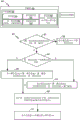
The encoder may determine the final shift value by optimizing a series of estimated shift values in multiple stages. For example, based on the comparison values generated by the stereo pre-processed and resampled versions of the first and second audio signals, the encoder may first estimate a "tentative" shift value. The encoder may generate interpolated comparison values associated with shift values that approximate the estimated "tentative" shift value. The encoder may determine a second estimated "interpolated" shift value based on the interpolated comparison value. For example, the second estimated "interpolated" shift value may correspond to a particular interpolated comparison value that indicates a higher temporal similarity (or smaller difference) than the remaining interpolated comparison value and the first estimated "tentative" shift value. If the second estimated "interpolated" shift value for the current frame (e.g., the first frame of the first audio signal) is different from the final shift value for the previous frame (e.g., the frame of the first audio signal that precedes the first frame), then the "interpolated" shift value for the current frame is further "modified" to improve the temporal similarity between the first audio signal and the shifted second audio signal. In particular, by searching around the second estimated "interpolated" shift value of the current frame and the final estimated shift value of the previous frame, the third estimated "revised" shift value may correspond to a more accurate measure of temporal similarity. The third estimated "correction" shift value is further adjusted to estimate the final shift value by limiting any spurious changes in shift values between frames, and further control is exercised to not switch the negative shift value to the positive shift value (or vice versa) in two consecutive (or consecutive) frames as described herein.
In some examples, the encoder may avoid switching between positive and negative shift values in consecutive frames or in neighboring frames, or vice versa. For example, based on an estimated "interpolate" or "correct" shift value for a first frame and a corresponding estimated "interpolate" or "correct" or final shift value in a particular frame preceding the first frame, the encoder may set the final shift value to a particular value (e.g., 0) indicating no time shift. To illustrate, in response to determining that one of the estimated "tentative" or "interpolated" or "corrected" shift values for the current frame is positive and the other of the estimated "tentative" or "interpolated" or "corrected" or "final" estimated shift values for the previous frame (e.g., the frame preceding the first frame) is negative, the encoder may set the final shift value for the current frame (e.g., the first frame) to indicate no time shift, i.e., shift1 = 0. Alternatively, in response to determining that one of the estimated "tentative" or "interpolated" or "corrected" shift values for the current frame is negative and the other of the estimated "tentative" or "interpolated" or "corrected" or "final" estimated shift values for the previous frame (e.g., the frame preceding the first frame) is positive, the encoder may also set the final shift value for the current frame (e.g., the first frame) to indicate no time shift, i.e., shift1 = 0.
The encoder may select a frame of the first audio signal or the second audio signal as a "reference" or "target" based on the shift value. For example, in response to determining that the final shift value is positive, the encoder may generate a reference channel or signal indicator having a first value (e.g., 0) indicating that the first audio signal is a "reference" signal and the second audio signal is a "target" signal. Alternatively, in response to determining that the final shift value is negative, the encoder may generate a reference channel or signal indicator having a second value (e.g., 1) that indicates that the second audio signal is a "reference" signal and the first audio signal is a "target" signal.
The encoder may estimate a relative gain (e.g., a relative gain parameter) associated with the reference signal and the non-causally shifted target signal. For example, in response to determining that the final shift value is positive, the encoder may estimate the gain value to normalize or equalize the energy or power level of the first audio signal relative to the second audio signal offset by a non-causal shift value (e.g., an absolute value of the final shift value). Alternatively, in response to determining that the final shift value is negative, the encoder may estimate the gain value to normalize or equalize the power level of the non-causal shifted first audio signal relative to the second audio signal. In some examples, the encoder may estimate the gain value to normalize or equalize the energy or power level of the "reference" signal relative to the non-causally shifted "target" signal. In other examples, the encoder may estimate the gain value (e.g., the relative gain value) based on a reference signal relative to the target signal (e.g., the non-shifted target signal).
The encoder may generate at least one encoded signal (e.g., a mid signal, a side signal, or both) based on the reference signal, the target signal, the non-causal shift value, and the relative gain parameter. The side signal may correspond to a difference between a first sample of a first frame of the first audio signal and a selected sample of a selected frame of the second audio signal. The encoder may select the selected frame based on the final shift value. Fewer bits are available to encode the side channel signal due to the reduced difference between the first sample and the selected sample as compared to other samples of the second audio signal corresponding to frames of the second audio signal (received by the device concurrently with the first frame). The transmitter of the device may transmit at least one encoded signal, a non-causal shift value, a relative gain parameter, a reference channel or signal indicator, or a combination thereof.
The encoder may generate at least one encoded signal (e.g., a mid signal, a side signal, or both) based on a reference signal, a target signal, a non-causal shift value, a relative gain parameter, a low band parameter of a particular frame of the first audio signal, a high band parameter of a particular frame, or a combination thereof. The particular frame may precede the first frame. Some low band parameters, high band parameters, or a combination thereof from one or more previous frames may be used to encode the mid signal, side signal, or both of the first frame. Encoding the mid signal, the side signal, or both based on the low band parameter, the high band parameter, or a combination thereof may improve the estimation of the non-causal shift value and the inter-channel relative gain parameter. The low band parameters, high band parameters, or combinations thereof may include pitch parameters, speech parameters, coder type parameters, low band energy parameters, high band energy parameters, tilt parameters, pitch gain parameters, FCB gain parameters, coding mode parameters, speech activity parameters, noise estimation parameters, signal-to-noise ratio parameters, formant parameters, speech/music decision parameters, non-causal shifts, inter-channel gain parameters, or combinations thereof. The transmitter of the device may transmit at least one encoded signal, a non-causal shift value, a relative gain parameter, a reference channel (or signal) indicator, or a combination thereof.
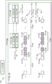
Referring to FIG. 1, a particular illustrative example of a system is disclosed and is generally designated 100. The system 100 includes a first device 104 communicatively coupled to a second device 106 via a network 120. Network 120 may include one or more wireless networks, one or more wired networks, or a combination thereof.
The first device 104 may include an encoder 114, a transmitter 110, one or more input interfaces 112, or a combination thereof. A first input interface of the input interfaces 112 may be coupled to a first microphone 146. A second input interface of the input interface 112 may be coupled to a second microphone 148. The encoder 114 may include the time equalizer 108 and may be configured to down-mix and encode a plurality of audio signals, as described herein. The first device 104 may also include a memory 153 configured to store analysis data 190. The second device 106 may include a decoder 118. The decoder 118 may include a time balancer 124 configured to up-mix and render multiple channels. The second device 106 may be coupled to the first speaker 142, the second speaker 144, or both.
During operation, the first device 104 may receive the first audio signal 130 from the first microphone 146 via the first input interface and may receive the second audio signal 132 from the second microphone 148 via the second input interface. The first audio signal 130 may correspond to one of a right channel signal or a left channel signal. The second audio signal 132 may correspond to the other of the right channel signal or the left channel signal. The sound source 152 (e.g., user, speaker, ambient noise, musical instrument, etc.) may be closer to the first microphone 146 than the second microphone 148. Thus, an audio signal from sound source 152 may be received at input interface 112 via first microphone 146 at an earlier time than via second microphone 148. This inherent delay in the acquisition of multi-channel signals via multiple microphones may introduce a time shift between the first audio signal 130 and the second audio signal 132.
The time equalizer 108 may be configured to estimate a temporal offset between audio captured at the microphones 146, 148. The temporal offset may be estimated based on a delay between a first frame of the first audio signal 130 and a second frame of the second audio signal 132, wherein the second frame includes substantially similar content as the first frame. For example, the time equalizer 108 may determine a cross-correlation between the first frame and the second frame. Cross-correlation may measure the similarity of two frames in terms of the lag of one frame relative to the other. Based on the cross-correlation, the time equalizer 108 may determine a delay (e.g., a lag) between the first frame and the second frame. The time equalizer 108 may estimate a temporal offset between the first audio signal 130 and the second audio signal 132 based on the delay and the historical delay data.
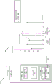
The historical data may include a delay between a frame retrieved from the first microphone 146 and a corresponding frame retrieved from the second microphone 148. For example, the time equalizer 108 may determine a cross-correlation (e.g., hysteresis) between a previous frame associated with the first audio signal 130 and a corresponding frame associated with the second audio signal 132. Each hysteresis may be represented by a "comparison value". That is, the comparison value may indicate a time shift (k) between a frame of the first audio signal 130 and a corresponding frame of the second audio signal 132. According to one implementation, the comparison value of the previous frame may be stored at the memory 153. Smoother 192 of time equalizer 108 may "smooth" (or average) the comparison values within the long term frame set and use the long term smoothed comparison values to estimate a temporal offset (e.g., "shift") between first audio signal 130 and second audio signal 132.
For purposes of illustration, if CompVal N (k) Representing the comparison value of frame N at shift k, frame N may have comparison values k=t_min (minimum shift) to k=t_max (maximum shift). Smoothing may be performed to enable long-term comparison of values By->
By-> To represent. The function f in the above equation may be a function of all past comparison values (or subsets) at shift (k). Long-term comparison value->
 An alternative representation of->
 The function f or g may be a simple finite impulse response (finite impulse response; FIR) filter or an infinite impulse response (infinite impulse response; IIR) filter, respectively. For example, the function g may be a single tap IIR filter, such that the long term comparison value +.>
 By->
By->
 Where α ε (0, 1.0). Thus, the long-term comparison value
 May be based on the instantaneous comparison value CompVal at frame N N (k) Long with one or more previous framesPhase comparison value
 Is included in the set of (a) and (b) is a weighted mix of (b) and (c). As the value of α increases, the amount of smoothing in the long-term comparison value increases. In a particular aspect, the function f may be an L tap FIR filter such that the long term comparison value +.>
 From the following components
 Wherein α1, α2, … …, and α0l correspond to weights. In a particular aspect, the particular weight of each of α11, α22, … …, and αl e (0, 1.0) and α1, α2, … …, and αl can be the same as or different from another weight of α1, α2, … …, and αl. Thus, long-term comparison value +. >
 May be based on the instantaneous comparison value CompVal at frame N N (k) CompVal compared with the comparison value in the previous (L-1) frames N-i (k) Is included in the set of (a) and (b) is a weighted mix of (b) and (c).
The smoothing techniques described above may substantially normalize shift estimates between voiced frames, unvoiced frames, and transition frames. The normalized shift estimation may reduce sample repetition and artifact skipping at frame boundaries. In addition, the normalized shift estimation may result in reduced side channel energy, which may improve coding efficiency.
The time equalizer 108 may determine a final shift value 116 (e.g., a non-causal shift value) that indicates a shift (e.g., a non-causal shift) of the first audio signal 130 (e.g., a "target") relative to the second audio signal 132 (e.g., a "reference"). The final shift value 116 may be based on the instantaneous comparison value CompVal N (k) Long term comparison For example, the smoothing operations described above may be performed on trial shift values, on interpolation shift values, on correction shift values, or combinations thereof, as described with respect to FIG. 5Description. The final shift value 116 may be based on the tentative shift value, the interpolated shift value, and the corrected shift value, as described with respect to fig. 5. A first value (e.g., a positive value) of the final shift value 116 may indicate that the second audio signal 132 is delayed relative to the first audio signal 130. A second value (e.g., a negative value) of the final shift value 116 may indicate that the first audio signal 130 is delayed relative to the second audio signal 132. A third value (e.g., 0) of the final shift value 116 may indicate no delay between the first audio signal 130 and the second audio signal 132.
In some implementations, a third value (e.g., 0) of the final shift value 116 may indicate that the delay between the first audio signal 130 and the second audio signal 132 has switched signs. For example, a first particular frame of the first audio signal 130 may precede the first frame. The first particular frame and the second particular frame of the second audio signal 132 may correspond to the same sound emitted by the sound source 152. The delay between the first audio signal 130 and the second audio signal 132 may be switched from delaying a first particular frame relative to a second particular frame to delaying the second frame relative to the first frame. Alternatively, the delay between the first audio signal 130 and the second audio signal 132 may be switched from delaying the second particular frame relative to the first particular frame to delaying the first frame relative to the second particular frame. In response to determining that the delay between the first audio signal 130 and the second audio signal 132 has switched signs, the time equalizer 108 may set the final shift value 116 to indicate a third value (e.g., 0).
The time equalizer 108 may generate the reference signal indicator 164 based on the final shift value 116. For example, in response to determining that the final shift value 116 indicates a first value (e.g., a positive value), the time equalizer 108 may generate the reference signal indicator 164 with a first value (e.g., 0) indicating that the first audio signal 130 is a "reference" signal. In response to determining that the final shift value 116 indicates a first value (e.g., a positive value), the time equalizer 108 may determine that the second audio signal 132 corresponds to a "target" signal. Alternatively, in response to determining that the final shift value 116 indicates a second value (e.g., a negative value), the time equalizer 108 may generate a reference signal indicator 164 having a second value (e.g., 1) that indicates that the second audio signal 132 is a "reference" signal. In response to determining that the final shift value 116 indicates a second value (e.g., a negative value), the time equalizer 108 may determine that the first audio signal 130 corresponds to a "target" signal. In response to determining that the final shift value 116 indicates a third value (e.g., 0), the time equalizer 108 may generate a reference signal indicator 164 having a first value (e.g., 0) indicating that the first audio signal 130 is a "reference" signal. In response to determining that the final shift value 116 indicates a third value (e.g., 0), the time equalizer 108 may determine that the second audio signal 132 corresponds to a "target" signal. Alternatively, in response to determining that the final shift value 116 indicates a third value (e.g., 0), the time equalizer 108 may generate a reference signal indicator 164 having a second value (e.g., 1) that indicates that the second audio signal 132 is a "reference" signal. In response to determining that the final shift value 116 indicates a third value (e.g., 0), the time equalizer 108 may determine that the first audio signal 130 corresponds to a "target" signal. In some implementations, in response to determining that the final shift value 116 indicates a third value (e.g., 0), the time equalizer 108 may leave the reference signal indicator 164 unchanged. For example, the reference signal indicator 164 may be the same as the reference signal indicator corresponding to the first particular frame of the first audio signal 130. The time equalizer 108 may generate a non-causal shift value 162 that indicates the absolute value of the final shift value 116.
The time equalizer 108 may generate gain parameters 160 (e.g., codec gain parameters) based on samples of the "target" signal and based on samples of the "reference" signal. For example, the time equalizer 108 may select samples of the second audio signal 132 based on the non-causal shift value 162. Alternatively, the time equalizer 108 may select samples of the second audio signal 132 independent of the non-causal shift value 162. In response to determining that the first audio signal 130 is a reference signal, the time equalizer 108 may determine gain parameters 160 for the selected samples based on the first samples of the first frame of the first audio signal 130. Alternatively, in response to determining that the second audio signal 132 is a reference signal, the time equalizer 108 may determine the gain parameter 160 for the first sample based on the selected sample. As an example, the gain parameter 160 may be based on one of the following equations:


wherein g D Corresponding to the relative gain parameter 160 for the downmix process, ref (N) corresponds to samples of the "reference" signal, N 1 A non-causal shift value 162 corresponding to the first frame, and Targ (n+n) 1 ) Corresponding to samples of the "target" signal. Gain parameter 160 (g) D ) Modifications may be made, for example, based on one of equations 1 a-1 f to incorporate long-term smoothing/hysteresis logic to avoid large jumps in gain between frames. When the target signal includes the first audio signal 130, the first samples may include samples of the target signal and the selected samples may include samples of the reference signal. When the target signal includes the second audio signal 132, the first samples may include samples of the reference signal, and the selected samples may include samples of the target signal.
In some implementations, the time equalizer 108 may generate gain parameters independent of the reference signal indicator 164 based on processing the first audio signal 130 as a reference signal and processing the second audio signal 132 as a target signal160. For example, ref (N) -based samples (e.g., first samples) corresponding to the first audio signal 130 and Targ (n+n) 1 ) The time equalizer 108 may generate the gain parameter 160 corresponding to one of equations 1a through 1f of samples (e.g., selected samples) of the second audio signal 132. In an alternative implementation, the time equalizer 108 may generate the gain parameter 160 independent of the reference signal indicator 164 based on treating the second audio signal 132 as a reference signal and treating the first audio signal 130 as a target signal. For example, ref (N) corresponds to a sample (e.g., a selected sample) of the second audio signal 132 and Targ (n+n) 1 ) The time equalizer 108 may generate the gain parameter 160 corresponding to one of equations 1a through 1f of a sample (e.g., a first sample) of the first audio signal 130.
Based on the first samples, the selected samples, and the relative gain parameters 160 for the downmix process, the time equalizer 108 may generate one or more encoded signals 102 (e.g., a center channel signal, a side channel signal, or both). For example, the time equalizer 108 may generate an intermediate signal based on one of the following equations:
M=Ref(n)+g D Targ(n+N 1 ) Equation 2a
M=Ref(n)+Targ(n+N 1 ) Equation 2b
M=DMXFAC*Ref(n)+(1-DMXFAC)*g D Targ(n+N 1 ) Equation 2c
M=DMXFAC*Ref(n)+(1-DMXFAC)*Targ(n+N 1 ) Equation 2d
Wherein M corresponds to the intermediate channel signal, g D Corresponding to the relative gain parameter 160 for the downmix process, ref (N) corresponds to samples of the "reference" signal, N 1 A non-causal shift value 162 corresponding to the first frame, and Targ (n+n) 1 ) Corresponding to samples of the "target" signal. Dmxfc may correspond to a downmix factor, as further described with reference to fig. 19.
For example, the time equalizer 108 may generate the side channel signal based on one of the following equations:
S=Ref(n)-g D Targ(n+N 1 ) Equation 3a
S=g D Ref(n)-Targ(n+N 1 ) Equation 3b
S=(1-DMXFAC)*Ref(n)-(DMXFAC)*g D Targ(n+N 1 ) Equation 3c
S=(1-DMXFAC)*Ref(n)-(DMXFAC)*Targ(n+N 1 ) Equation 3d
Wherein S corresponds to the side channel signal, g D Corresponding to the relative gain parameter 160 for the downmix process, ref (N) corresponds to samples of the "reference" signal, N 1 A non-causal shift value 162 corresponding to the first frame, and Targ (n+n) 1 ) Corresponding to samples of the "target" signal.
The transmitter 110 may transmit the encoded signal 102 (e.g., a center channel signal, a side channel signal, or both), a reference signal indicator 164, a non-causal shift value 162, a gain parameter 160, or a combination thereof, to the second device 106 via the network 120. In some implementations, the transmitter 110 may store the encoded signal 102 (e.g., a center channel signal, a side channel signal, or both), the reference signal indicator 164, the non-causal shift value 162, the gain parameter 160, or a combination thereof, at a device or local device of the network 120 for later further processing or decoding.
The system 100 may thus enable the time equalizer 108 to encode the side channel signal using fewer bits than the intermediate signal. The first sample of the first frame of the first audio signal 130 and the selected sample of the second audio signal 132 may correspond to the same sound emitted by the sound source 152, and thus, the difference between the first sample and the selected sample may be less than the differences between the first sample and other samples of the second audio signal 132. The side channel signal may correspond to a difference between the first sample and the selected sample.
Referring to FIG. 2, a particular illustrative example of a system is disclosed and is generally designated 200. The system 200 includes a first device 204 coupled to the second device 106 via the network 120. The first device 204 may correspond to the first device 104 of fig. 1. The system 200 differs from the system 100 of fig. 1 in that the first device 204 is coupled to more than two microphones. For example, the first device 204 may be coupled to the first microphone 146, the nth microphone 248, and one or more additional microphones (e.g., the second microphone 148 of fig. 1). The second device 106 may be coupled to the first speaker 142, the Y-th speaker 244, one or more additional speakers (e.g., the second speaker 144), or a combination thereof. The first device 204 may include an encoder 214. Encoder 214 may correspond to encoder 114 of fig. 1. The encoder 214 may include one or more time equalizers 208. For example, the time equalizer 208 may include the time equalizer 108 of fig. 1.
During operation, the first device 204 may receive more than two audio signals. For example, the first device 204 may receive the first audio signal 130 via the first microphone 146, the nth audio signal 232 via the nth microphone 248, and one or more additional audio signals (e.g., the second audio signal 132) via additional microphones (e.g., the second microphone 148).
The time equalizer 208 may generate one or more reference signal indicators 264, final shift values 216, non-causal shift values 262, gain parameters 260, the encoded signal 202, or a combination thereof. For example, the time equalizer 208 may determine that the first audio signal 130 is a reference signal and each of the nth audio signal 232 and the additional audio signal is a target signal. The time equalizer 208 may generate the reference signal indicator 164, the final shift value 216, the non-causal shift value 262, the gain parameter 260, and the encoded signal 202 corresponding to each of the first and nth audio signals 130, 232 and the additional audio signal.
The reference signal indicator 264 may include the reference signal indicator 164. The final shift value 216 may include a final shift value 116 indicating a shift of the second audio signal 132 relative to the first audio signal 130, a second final shift value indicating a shift of the nth audio signal 232 relative to the first audio signal 130, or both. The non-causal shift value 262 may include a non-causal shift value 162 corresponding to the absolute value of the final shift value 116, a second non-causal shift value corresponding to the absolute value of the second final shift value, or both. Gain parameters 260 may include gain parameters 160 of selected samples of second audio signal 132, second gain parameters of selected samples of nth audio signal 232, or both. The encoded signals 202 may include at least one of the encoded signals 102. For example, the encoded signal 202 may include a side channel signal corresponding to first samples of the first audio signal 130 and selected samples of the second audio signal 132, a second side channel corresponding to the first samples and selected samples of the nth audio signal 232, or both. The encoded signal 202 may include an intermediate channel signal corresponding to the first sample, the selected sample of the second audio signal 132, and the selected sample of the nth audio signal 232.
In some implementations, the time equalizer 208 may determine a plurality of reference signals and corresponding target signals, as described with reference to fig. 15. For example, the reference signal indicator 264 may include a reference signal indicator corresponding to each pair of a reference signal and a target signal. To illustrate, the reference signal indicator 264 may include the reference signal indicator 164 corresponding to the first audio signal 130 and the second audio signal 132. The final shift value 216 may include a final shift value corresponding to each pair of reference and target signals. For example, the final shift value 216 may include the final shift value 116 corresponding to the first audio signal 130 and the second audio signal 132. The non-causal shift value 262 may include a non-causal shift value corresponding to each pair of reference and target signals. For example, the non-causal shift value 262 may include a non-causal shift value 162 corresponding to the first audio signal 130 and the second audio signal 132. Gain parameters 260 may include gain parameters corresponding to each pair of reference and target signals. For example, the gain parameters 260 may include gain parameters 160 corresponding to the first audio signal 130 and the second audio signal 132. The encoded signal 202 may include a center channel signal and a side channel signal corresponding to each pair of reference and target signals. For example, the encoded signal 202 may include the encoded signal 102 corresponding to the first audio signal 130 and the second audio signal 132.
The transmitter 110 may transmit the reference signal indicator 264, the non-causal shift value 262, the gain parameter 260, the encoded signal 202, or a combination thereof, to the second device 106 via the network 120. Based on the reference signal indicator 264, the non-causal shift value 262, the gain parameter 260, the encoded signal 202, or a combination thereof, the decoder 118 may generate one or more output signals. For example, the decoder 118 may output the first output signal 226 via the first speaker 142, the Y output signal 228 via the Y speaker 244, one or more additional output signals (e.g., the second output signal 128) via one or more additional speakers (e.g., the second speaker 144), or a combination thereof.
The system 200 may thus enable the time equalizer 208 to encode more than two audio signals. For example, by generating the side channel signal based on the non-causal shift value 262, the encoded signal 202 may include a plurality of side channel signals encoded using fewer bits than a corresponding center channel.
Referring to FIG. 3, an illustrative example of a sample is shown and is designated generally 300. As described herein, at least a subset of the samples 300 may be encoded by the first device 104.
The samples 300 may include a first sample 320 corresponding to the first audio signal 130, a second sample 350 corresponding to the second audio signal 132, or both. The first sample 320 may include sample 322, sample 324, sample 326, sample 328, sample 330, sample 332, sample 334, sample 336, one or more additional samples, or a combination thereof. The second sample 350 may include sample 352, sample 354, sample 356, sample 358, sample 360, sample 362, sample 364, sample 366, one or more additional samples, or a combination thereof.
The first audio signal 130 may correspond to a plurality of frames (e.g., frame 302, frame 304, frame 306, or a combination thereof). Each of the plurality of frames may correspond to a subset of samples of the first sample 320 (e.g., to 20ms, such as 640 samples at 32kHz or 960 samples at 48 kHz). For example, frame 302 may correspond to sample 322, sample 324, one or more additional samples, or a combination thereof. Frame 304 may correspond to sample 326, sample 328, sample 330, sample 332, one or more additional samples, or a combination thereof. Frame 306 may correspond to sample 334, sample 336, one or more additional samples, or a combination thereof.
Sample 322 may be received at the input interface 112 of fig. 1 at approximately the same time as sample 352. Sample 324 may be received at the input interface 112 of fig. 1 at approximately the same time as sample 354. Sample 326 may be received at the input interface 112 of fig. 1 at approximately the same time as sample 356. Sample 328 may be received at the input interface 112 of fig. 1 at approximately the same time as sample 358. Sample 330 may be received at the input interface 112 of fig. 1 at approximately the same time as sample 360. Sample 332 may be received at the input interface 112 of fig. 1 at approximately the same time as sample 362. Sample 334 may be received at substantially the same time as sample 364 at input interface 112 of fig. 1. Sample 336 may be received at the input interface 112 of fig. 1 at approximately the same time as sample 366.
A first value (e.g., a positive value) of the final shift value 116 may indicate that the second audio signal 132 is delayed relative to the first audio signal 130. For example, a first value of the final shift value 116 (e.g., +x ms or +y samples, where X and Y include positive real numbers) may indicate that the frame 304 (e.g., samples 326-332) corresponds to samples 358-364. Samples 326-332 and samples 358-364 may correspond to the same sound emitted from sound source 152. Samples 358-364 may correspond to frame 344 of the second audio signal 132. The illustration of the samples with the mesh lines in one or more of fig. 1-15 may indicate that the samples correspond to the same sound. For example, samples 326-332 and samples 358-364 are illustrated in fig. 3 as having a mesh line to indicate that samples 326-332 (e.g., frame 304) and samples 358-364 (e.g., frame 344) correspond to the same sound emitted from sound source 152.
It should be appreciated that the temporal offset of Y samples, as shown in fig. 3, is illustrative. For example, the temporal offset may correspond to a number Y of samples that is greater than or equal to 0. In the first case of a temporal offset y=0 samples, samples 326-332 (e.g., corresponding to frame 304) and samples 356-362 (e.g., corresponding to frame 344) may exhibit high similarity without any frame offset. In the second case of a temporal offset y=2 samples, frames 304 and 344 may be offset by 2 samples. In this case, the first audio signal 130 may be received at the input interface 112 prior to the second audio signal 132 y=2 samples or x= (2/Fs) ms, where Fs corresponds to a sampling rate in kHz. In some cases, the temporal offset Y may include a non-integer value, e.g., y=1.6 samples, which corresponds to x=0.05 ms at 32 kHz.
The time equalizer 108 of fig. 1 may generate the encoded signal 102 by encoding the samples 326-332 and the samples 358-364, as described with reference to fig. 1. The time equalizer 108 may determine that the first audio signal 130 corresponds to a reference signal and the second audio signal 132 corresponds to a target signal.
Referring to FIG. 4, an illustrative example of a sample is shown and is designated generally as 400. The sample 400 differs from the sample 300 in that the first audio signal 130 is delayed relative to the second audio signal 132.
A second value (e.g., a negative value) of the final shift value 116 may indicate that the first audio signal 130 is delayed relative to the second audio signal 132. For example, a second value of the final shift value 116 (e.g., -X ms or-Y samples, where X and Y include positive real numbers) may indicate that the frame 304 (e.g., samples 326-332) corresponds to samples 354-360. Samples 354-360 may correspond to frame 344 of second audio signal 132. Samples 354-360 (e.g., frame 344) and samples 326-332 (e.g., frame 304) may correspond to the same sound emitted by sound source 152.
It should be understood that the temporal offset of-Y samples is illustrative, as shown in fig. 4. For example, the temporal offset may correspond to a number of samples-Y that is less than or equal to 0. In the first case of a temporal offset y=0 samples, samples 326-332 (e.g., corresponding to frame 304) and samples 356-362 (e.g., corresponding to frame 344) may exhibit high similarity without any frame offset. In the second case of a temporal offset y= -6 samples, frames 304 and 344 may be offset by 6 samples. In this case, the first audio signal 130 may be received at the input interface 112 after the second audio signal 132 by y= -6 samples or x= (-6/Fs) ms, where Fs corresponds to a sampling rate in kHz. In some cases, the temporal offset Y may include a non-integer value, e.g., y= -3.2 samples, which corresponds to x= -0.1ms at 32 kHz.
The time equalizer 108 of fig. 1 may generate the encoded signal 102 by encoding samples 354-360 and samples 326-332, as described with reference to fig. 1. The time equalizer 108 may determine that the second audio signal 132 corresponds to the reference signal and the first audio signal 130 corresponds to the target signal. In particular, the time equalizer 108 may estimate the non-causal shift value 162 from the final shift value 116, as described with reference to fig. 5. Based on the sign of the final shift value 116, the time equalizer 108 may identify (e.g., designate) one of the first audio signal 130 or the second audio signal 132 as a reference signal and the other of the first audio signal 130 or the second audio signal 132 as a target signal.
Referring to FIG. 5, an illustrative example of a system is shown and is generally designated 500. System 500 may correspond to system 100 of fig. 1. For example, the system 100, the first device 104, or both of fig. 1 may include one or more components of the system 500. The time equalizer 108 may include a resampler 504, a signal comparator 506, an interpolator 510, a shift optimizer 511, a shift change analyzer 512, an absolute shift generator 513, a reference signal designator 508, a gain parameter generator 514, a signal generator 516, or a combination thereof.
During operation, resampler 504 may generate one or more resampled signals, as further described with reference to fig. 6. For example, the resampler 504 may generate the first resampled signal 530 by resampling (e.g., downsampling or upsampling) the first audio signal 130 based on a resampling (e.g., downsampling or upsampling) factor (D) (e.g., 1). The resampler 504 may generate the second resampled signal 532 by resampling the second audio signal 132 based on the resampling factor (D). Resampler 504 may provide first resampled signal 530, second resampled signal 532, or both to signal comparator 506.
The signal comparator 506 may generate a comparison value 534 (e.g., a difference value, a variance value, a similarity value, a coherence value, or a cross-correlation value), a tentative shift value 536, or both, as further described with reference to fig. 7. For example, the signal comparator 506 may generate the comparison value 534 based on the first resampled signal 530 and a plurality of shift values applied to the second resampled signal 532, as further described with reference to fig. 7. The signal comparator 506 may determine a tentative shift value 536 based on the comparison value 534, as further described with reference to fig. 7. According to one implementation, the signal comparator 506 may retrieve the comparison value of the previous frame of the resampled signals 530, 532 and may modify the comparison value 534 based on long-term smoothing operations using the comparison value of the previous frame. For example, the comparison value 534 may include a long-term comparison value for the current frame (N)  And can be made of
 Where α ε (0, 1.0). Thus, long-term comparison value +.>
 May be based on the instantaneous comparison value CompVal at frame N N (k) Long-term comparison value +.>
 Is included in the set of (a) and (b) is a weighted mix of (b) and (c). As the value of α increases, the amount of smoothing in the long-term comparison value increases.
The first resampled signal 530 may include fewer samples or more samples than the first audio signal 130. The second resampled signal 532 may include fewer samples or more samples than the second audio signal 132. Determining the comparison value 534 based on fewer samples of the resampled signals (e.g., the first resampled signal 530 and the second resampled signal 532) may use fewer resources (e.g., time, number of operations, or both) than based on samples of the original signals (e.g., the first audio signal 130 and the second audio signal 132). Determining the comparison value 534 based on more samples of the resampled signal (e.g., the first resampled signal 530 and the second resampled signal 532) may increase accuracy compared to samples based on the original signal (e.g., the first audio signal 130 and the second audio signal 132). Signal comparator 506 may provide comparison value 534, tentative shift value 536, or both to interpolator 510.
The interpolator 510 may extend the tentative shift value 536. For example, the interpolator 510 may generate the interpolated shift value 538, as further described with reference to fig. 8. For example, interpolator 510 may generate an interpolated comparison value that corresponds to a shift value that is close to trial shift value 536 by interpolating comparison value 534. The interpolator 510 may determine the interpolation shift value 538 based on the interpolation comparison value and the comparison value 534. The comparison value 534 may be based on a coarser granularity of the shift value. For example, the comparison value 534 may be based on a first subset of the set of shift values such that a difference between a first shift value of the first subset and each second shift value of the first subset is greater than or equal to a threshold (e.g., 1). The threshold may be based on a resampling factor (D).
The interpolated comparison value may be based on a finer granularity of shift values that are close to the resampled tentative shift value 536. For example, the interpolated comparison value may be based on a second subset of the set of shift values such that the difference between the highest shift value of the second subset and the resampled tentative shift value 536 is less than the threshold (e.g., 1), and the difference between the lowest shift value of the second subset and the resampled tentative shift value 536 is less than the threshold. Determining the comparison value 534 based on a coarser granularity (e.g., a first subset) of the set of shift values may use fewer resources (e.g., time, operations, or both) than determining the comparison value 534 based on a finer granularity (e.g., all) of the set of shift values. Determining interpolated comparison values corresponding to the second subset of shift values may augment tentative shift values 536 based on finer granularity of smaller sets of shift values that are close to tentative shift values 536 without determining comparison values for each shift value corresponding to a set of shift values. Thus, determining tentative shift values 536 based on the first subset of shift values and determining interpolated shift values 538 based on the interpolated comparison values may balance resource usage and optimization of estimated shift values. The interpolator 510 may provide the interpolated shift value 538 to the shift optimizer 511.
According to one implementation, the interpolator 510 may retrieve interpolation shift values for a previous frame and may modify the interpolation shift values 538 based on a long-term smoothing operation using the interpolation shift values for the previous frame. For example, the interpolation shift value 538 may include a long-term interpolation shift value for the current frame (N) And can be made of
 Where α ε (0, 1.0). Thus, the long-term interpolation shift value +.>
 May be based on the instantaneous interpolated shift value InterVal at frame N N (k) Long-term interpolation shift value +_ from one or more previous frames>
 Is included in the set of (a) and (b) is a weighted mix of (b) and (c). As the value of α increases, the amount of smoothing in the long-term comparison value increases.
The shift optimizer 511 may generate the corrected shift value 540 by optimizing the interpolated shift value 538, as further described with reference to fig. 9A-9C. For example, the shift optimizer 511 may determine whether the interpolated shift value 538 indicates that the shift change between the first audio signal 130 and the second audio signal 132 is greater than a shift change threshold, as further described with reference to fig. 9A. The shift change may be indicated by interpolating a difference (e.g., a change) between the shift value 538 and the first shift value associated with the frame 302 of fig. 3. In response to determining that the difference is less than or equal to the threshold, the shift optimizer 511 may set the corrected shift value 540 to the interpolated shift value 538. Alternatively, in response to determining that the difference is greater than the threshold, the shift optimizer 511 may determine a plurality of shift values corresponding to differences less than or equal to a shift change threshold, as further described with reference to fig. 9A. The shift optimizer 511 may determine a comparison value based on the first audio signal 130 and a plurality of shift values applied to the second audio signal 132. The shift optimizer 511 may determine a correction shift value 540 based on the comparison value, as further described with reference to fig. 9A. For example, the shift optimizer 511 may select a shift value of the plurality of shift values based on the comparison value and the interpolated shift value 538, as further described with reference to fig. 9A. The shift optimizer 511 may set a correction shift value 540 to indicate the selected shift value. The non-zero difference between the first shift value corresponding to frame 302 and the interpolated shift value 538 may indicate that some samples of the second audio signal 132 correspond to two frames (e.g., frame 302 and frame 304). For example, some samples of the second audio signal 132 may be copied during encoding. Alternatively, a non-zero difference may indicate that some samples of the second audio signal 132 correspond to neither frame 302 nor frame 304. For example, some samples of the second audio signal 132 may be lost during encoding. Setting the modified shift value 540 to one of a plurality of shift values may prevent large shift changes between consecutive (or adjacent) frames, thereby reducing the amount of sample loss or sample duplication during encoding. The shift optimizer 511 may provide a corrected shift value 540 to the shift change analyzer 512.
According to one implementation, the shift optimizer may retrieve the correction shift value of the previous frame and may modify the correction shift value 540 based on the long-term smoothing operation using the correction shift value of the previous frame. For example, the correction shift value 540 may include a long term correction shift value for the current frame (N) And can be made of->
 Where α ε (0, 1.0). Thus, the long-term correction shift value +.>
 The shift value AmendVal may be corrected based on the instant at frame N N (k) Long term correction shift value +_ from one or more previous frames>
 Is included in the set of (a) and (b) is a weighted mix of (b) and (c). As the value of α increases, the amount of smoothing in the long-term comparison value increases.
In some implementations, the shift optimizer 511 may adjust the interpolated shift value 538, as described with reference to fig. 9B. The shift optimizer 511 may determine a correction shift value 540 based on the adjusted interpolated shift value 538. In some implementations, the shift optimizer 511 may determine a correction shift value 540, as described with reference to fig. 9C.
The shift change analyzer 512 may determine whether the corrected shift value 540 indicates a switch or reversal in timing between the first audio signal 130 and the second audio signal 132, as described with reference to fig. 1. In particular, a reversal or switch in timing may indicate: for frame 302, the first audio signal 130 is received at the input interface 112 before the second audio signal 132, and for a subsequent frame (e.g., frame 304 or frame 306), the second audio signal 132 is received at the input interface before the first audio signal 130. Alternatively, a reversal or switch in timing may indicate: for frame 302, the second audio signal 132 is received at the input interface 112 before the first audio signal 130, and for a subsequent frame (e.g., frame 304 or frame 306), the first audio signal 130 is received at the input interface before the second audio signal 132. In other words, a switch or reversal in timing may indicate: the final shift value corresponding to frame 302 has a first sign (e.g., a positive-to-negative transition, or vice versa) that is different than the second sign of the modified shift value 540 corresponding to frame 304. Based on the corrected shift value 540 and the first shift value associated with the frame 302, the shift change analyzer 512 may determine whether the delay between the first audio signal 130 and the second audio signal 132 has switched signs, as further described with reference to fig. 10A. In response to determining that the delay between the first audio signal 130 and the second audio signal 132 has switched signs, the shift change analyzer 512 may set the final shift value 116 to a value (e.g., 0) indicating no time shift. Alternatively, in response to determining that the delay between the first audio signal 130 and the second audio signal 132 has not switched signs, the shift change analyzer 512 may set the final shift value 116 to a modified shift value 540, as further described with reference to fig. 10A. The shift change analyzer 512 may generate an estimated shift value by optimizing the modified shift value 540, as further described with reference to fig. 10A, 11. The shift change analyzer 512 may set the final shift value 116 to an estimated shift value. Setting the final shift value 116 to indicate no time shift may reduce distortion at the decoder by avoiding time shifting of the first audio signal 130 and the second audio signal 132 in opposite directions for consecutive (or adjacent) frames of the first audio signal 130. The shift change analyzer 512 may provide the final shift value 116 to the reference signal designator 508, to the absolute shift generator 513, or both. In some implementations, the shift change analyzer 512 may determine the final shift value 116, as described with reference to fig. 10B.
By applying an absolute function to the final shift value 116, the absolute shift generator 513 may generate a non-causal shift value 162. The absolute shift generator 513 may provide the non-causal shift value 162 to the gain parameter generator 514.
The reference signal designator 508 may generate the reference signal indicator 164 as further described with reference to fig. 12-13. For example, the reference signal indicator 164 may have a first value indicating that the first audio signal 130 is a reference signal or a second value indicating that the second audio signal 132 is a reference signal. The reference signal designator 508 may provide the reference signal indicator 164 to the gain parameter generator 514.
The gain parameter generator 514 may select samples of the target signal (e.g., the second audio signal 132) based on the non-causal shift value 162. For example, in response to determining that the non-causal shift value 162 has a first value (e.g., +x ms or +y samples, where X and Y include positive real numbers), the gain parameter generator 514 may select samples 358-364. In response to determining that the non-causal shift value 162 has a second value (e.g., -X ms or-Y samples), the gain parameter generator 514 may select samples 354-360. In response to determining that the non-causal shift value 162 has a value (e.g., 0) indicating no time shift, the gain parameter generator 514 may select samples 356 through 362.
The gain parameter generator 514 may determine whether the first audio signal 130 is a reference signal or the second audio signal 132 is a reference signal based on the reference signal indicator 164. Based on samples 326-332 of frame 304 and selected samples (e.g., samples 354-360, samples 356-362, or samples 358-364) of second audio signal 132, gain parameter generator 514 may generate gain parameters 160, as described with reference to fig. 1. For example, gain parameter generator 514 may generate gain parameter 160 based on one or more of equations 1 a-1 f, where g D Corresponding to the gain parameter 160, ref (N) corresponds to samples of the reference signal, and Targ (n+N) 1 ) Corresponding to samples of the target signal. To illustrate, when the non-causal shift value 162 has a first value (e.g., +x ms or +y samples, where X and Y include positive real numbers), ref (n) may correspond to samples 326-332 of the frame 304, and Targ (n+tn) 1 ) Samples 358-364, which may correspond to frame 344. In some implementations, ref (N) may correspond to a sample of the first audio signal 130, and Targ (n+n) 1 ) May correspond to samples of the second audio signal 132 as described with reference to fig. 1. In an alternative implementation, ref (N) may correspond to a sample of the second audio signal 132, and Targ (n+n) 1 ) May correspond to samples of the first audio signal 130, as described with reference to fig. 1.
The gain parameter generator 514 may provide the gain parameter 160, the reference signal indicator 164, the non-causal shift value 162, or a combination thereof to the signal generator 516. The signal generator 516 may generate the encoded signal 102 as described with reference to fig. 1. For example, the encoded signal 102 may include a first encoded signal frame 564 (e.g., a middle channel frame), a second encoded signal frame 566 (e.g., a side channel frame), or both. Signal generator 516 may generate first encoded signal frame 564 based on equation 2a or equation 2b, where M corresponds to first encoded signal frame 564, g D Corresponding to the gain parameter 160, ref (N) corresponds to samples of the reference signal, and Targ (n+N) 1 ) Corresponding to samples of the target signal. The signal generator 516 may be based on equation 3a orEquation 3b produces a second encoded signal frame 566, where S corresponds to the second encoded signal frame 566, g D Corresponding to the gain parameter 160, ref (N) corresponds to samples of the reference signal, and Targ (n+N) 1 ) Corresponding to samples of the target signal.
The time equalizer 108 may store the following in the memory 153: the first resampled signal 530, the second resampled signal 532, the comparison value 534, the trial shift value 536, the interpolation shift value 538, the correction shift value 540, the non-causal shift value 162, the reference signal indicator 164, the final shift value 116, the gain parameter 160, the first encoded signal frame 564, the second encoded signal frame 566, or a combination thereof. For example, analysis data 190 may include first resampled signal 530, second resampled signal 532, comparison value 534, tentative shift value 536, interpolation shift value 538, correction shift value 540, non-causal shift value 162, reference signal indicator 164, final shift value 116, gain parameter 160, first encoded signal frame 564, second encoded signal frame 566, or a combination thereof.
The smoothing techniques described above may substantially normalize shift estimates between voiced frames, unvoiced frames, and transition frames. The normalized shift estimation may reduce sample repetition and artifact skipping at frame boundaries. In addition, the normalized shift estimation may result in reduced side channel energy, which may improve coding efficiency.
Referring to FIG. 6, an illustrative example of a system is shown and is generally designated 600. System 600 may correspond to system 100 of fig. 1. For example, the system 100, the first device 104, or both of fig. 1 may include one or more components of the system 600.
Resampler 504 may generate first samples 620 of first resampled signal 530 by resampling (e.g., downsampling or upsampling) first audio signal 130 of fig. 1. Resampler 504 may generate second samples 650 of second resampled signal 532 by resampling (e.g., downsampling or upsampling) second audio signal 132 of fig. 1.
The first audio signal 130 may be sampled at a first sampling rate (Fs) to produce the first samples 320 of fig. 3. The first sampling rate (Fs) may correspond to a first rate (e.g., 16 kilohertz (kHz)) associated with a Wideband (WB) bandwidth, a second rate (e.g., 32 kHz) associated with an ultra wideband (SWB) bandwidth, a third rate (e.g., 48 kHz) associated with a Full Band (FB) bandwidth, or another rate. The second audio signal 132 may be sampled at a first sampling rate (Fs) to produce the second samples 350 of fig. 3.
In some implementations, the resampler 504 may pre-process the first audio signal 130 (or the second audio signal 132) before resampling the first audio signal 130 (or the second audio signal 132). The resampler 504 may pre-process the first audio signal 130 (or the second audio signal 132) by filtering the first audio signal 130 (or the second audio signal 132) based on an Infinite Impulse Response (IIR) filter (e.g., a first order IIR filter). The IIR filter may be based on the following equation:
H pre (z)=1/(1-αz -1 ) Equation 4
Where α is positive, e.g., 0.68 or 0.72. Performing de-emphasis (de-emphasis) prior to resampling may reduce effects such as aliasing, signal conditioning, or both. The first audio signal 130 (e.g., the preprocessed first audio signal 130) and the second audio signal 132 (e.g., the preprocessed second audio signal 132) may be resampled based on a resampling factor (D). The resampling factor (D) may be based on a first sampling rate (Fs) (e.g., d=fs/8, d=2fs, etc.).
In alternative implementations, the first audio signal 130 and the second audio signal 132 may be low pass filtered or decimated using an anti-aliasing filter prior to resampling. The decimation filter may be based on a resampling factor (D). In a particular example, in response to determining that the first sampling rate (Fs) corresponds to a particular rate (e.g., 32 kHz), the resampler 504 may select a decimation filter having a first cutoff frequency (e.g., pi/D or pi/4). Reducing aliasing by de-emphasizing the plurality of signals (e.g., the first audio signal 130 and the second audio signal 132) may be less computationally expensive than applying a decimation filter to the plurality of signals.
First sample 620 may include sample 622, sample 624, sample 626, sample 628, sample 630, sample 632, sample 634, sample 636, one or more additional samples, or a combination thereof. The first samples 620 may include a subset (e.g., 1/8) of the first samples 320 of fig. 3. Sample 622, sample 624, one or more additional samples, or a combination thereof may correspond to frame 302. Sample 626, sample 628, sample 630, sample 632, one or more additional samples, or a combination thereof may correspond to frame 304. Sample 634, sample 636, one or more additional samples, or a combination thereof may correspond to frame 306.
The second sample 650 may include sample 652, sample 654, sample 656, sample 658, sample 660, sample 662, sample 664, sample 667, one or more additional samples, or a combination thereof. The second samples 650 may include a subset (e.g., 1/8) of the second samples 350 of fig. 3. Samples 654-660 may correspond to samples 354-360. For example, samples 654-660 may include a subset (e.g., 1/8) of samples 354-360. Samples 656 through 662 may correspond to samples 356 through 362. For example, samples 656 to 662 may include a subset (e.g., 1/8) of samples 356 to 362. Samples 658-664 may correspond to samples 358-364. For example, samples 658-664 may include a subset (e.g., 1/8) of samples 358-364. In some implementations, the resampling factor may correspond to a first value (e.g., 1), where samples 622-636 and samples 652-667 of fig. 6 may be similar to samples 322-336 and samples 352-366 of fig. 3, respectively.
Resampler 504 may store first sample 620, second sample 650, or both in memory 153. For example, the analysis data 190 may include the first sample 620, the second sample 650, or both.
Referring to FIG. 7, an illustrative example of a system is shown and is generally designated 700. The system 700 may correspond to the system 100 of fig. 1. For example, the system 100, the first device 104, or both of fig. 1 may include one or more components of the system 700.
Memory 153 may store a plurality of shift values 760. The shift value 760 may include a first shift value 764 (e.g., -X ms or-Y samples, where X and Y include positive real numbers), a second shift value 766 (e.g., + X ms or +y samples, where X and Y include positive real numbers), or both. The shift value 760 may range from a smaller shift value (e.g., a minimum shift value t_min) to a larger shift value (e.g., a maximum shift value t_max). The shift value 760 may indicate an expected time shift (e.g., a maximum expected time shift) between the first audio signal 130 and the second audio signal 132.
During operation, the signal comparator 506 may determine the comparison value 534 based on the first sample 620 and the shift value 760 applied to the second sample 650. For example, samples 626-632 may correspond to a first time (t). To illustrate, the input interface 112 of fig. 1 may receive samples 626-632 corresponding to the frame 304 at approximately a first time (t). The first shift value 764 (e.g., -X ms or-Y samples, where X and Y include positive real numbers) may correspond to a second time (t-1).
Samples 654-660 may correspond to a second time (t-1). For example, input interface 112 may receive samples 654-660 at approximately a second time (t-1). The signal comparator 506 may determine a first comparison value 714 (e.g., a difference value, a variance value, or a cross-correlation value) corresponding to the first shift value 764 based on the samples 626-632 and the samples 654-660. For example, the first comparison value 714 may correspond to an absolute value of the cross-correlation of samples 626-632 and samples 654-660. As another example, the first comparison value 714 may indicate a difference between samples 626-632 and samples 654-660.
The second shift value 766 (e.g., +x ms or +y samples, where X and Y include positive real numbers) may correspond to a third time (t+1). Samples 658-664 can correspond to a third time (t+1). For example, input interface 112 may receive samples 658-664 at approximately a third time (t+1). The signal comparator 506 may determine a second comparison value 716 (e.g., a difference value, a variance value, or a cross-correlation value) corresponding to the second shift value 766 based on the samples 626-632 and the samples 658-664. For example, the second comparison value 716 may correspond to an absolute value of the cross-correlation of samples 626-632 and samples 658-664. As another example, the second comparison value 716 may indicate a difference between samples 626-632 and samples 658-664. The signal comparator 506 may store the comparison value 534 in the memory 153. For example, the analysis data 190 may include the comparison value 534.
Signal comparator 506 may identify a selected comparison value 736 of comparison value 534 that has a value greater (or smaller) than other values of comparison value 534. For example, in response to determining that the second comparison value 716 is greater than or equal to the first comparison value 714, the signal comparator 506 may select the second comparison value 716 as the selected comparison value 736. In some implementations, the comparison value 534 may correspond to a cross-correlation value. In response to determining that second comparison value 716 is greater than first comparison value 714, signal comparator 506 may determine that samples 626-632 are more correlated with samples 658-664 than samples 654-660. The signal comparator 506 may select the second comparison value 716 indicative of a higher correlation as the selected comparison value 736. In other implementations, the comparison value 534 may correspond to a difference value (e.g., a change value). In response to determining that second comparison value 716 is less than first comparison value 714, signal comparator 506 may determine that samples 626-632 are more similar to samples 658-664 than samples 654-660 (e.g., the difference from samples 658-664 is less than the difference from samples 654-660). The signal comparator 506 may select the second comparison value 716 indicative of the smaller difference as the selected comparison value 736.
Selected comparison value 736 may indicate a higher degree of correlation (or smaller difference) than other values of comparison value 534. The signal comparator 506 may identify a tentative shift value 536 of the shift value 760 that corresponds to the selected comparison value 736. For example, in response to determining that the second shift value 766 corresponds to the selected comparison value 736 (e.g., the second comparison value 716), the signal comparator 506 may identify the second shift value 766 as the tentative shift value 536.
The signal comparator 506 may determine the selected comparison value 736 based on the following equation:

where maxcorr corresponds to the selected comparison value 736 and k corresponds to the shift value. w (n) l 'corresponds to the de-emphasized, resampled and windowed first audio signal 130, and w (n) r' corresponds to the de-emphasized, resampled and windowed second audio signal 132. For example, w (n) x l 'may correspond to samples 626-632, w (n-1) x r' may correspond to samples 654-660, w (n) x r 'may correspond to samples 656-662, and w (n+1) x r' may correspond to samples 658-664. K may correspond to a smaller shift value (e.g., a minimum shift value) of shift value 760, and K may correspond to a larger shift value (e.g., a maximum shift value) of shift value 760. In equation 5, w (n) ×l' corresponds to the first audio signal 130, regardless of whether the first audio signal 130 corresponds to a right (r) channel signal or a left (l) channel signal. In equation 5, w (n) ×r' corresponds to the second audio signal 132, regardless of whether the second audio signal 132 corresponds to a right (r) channel signal or a left (l) channel signal.
The signal comparator 506 may determine the tentative shift value 536 based on the following equation:

where T corresponds to trial shift value 536.
The signal comparator 506 may map the tentative shift value 536 from the resampled sample to the original sample based on the resampling factor (D) of fig. 6. For example, the signal comparator 506 may update the tentative shift value 536 based on the resampling factor (D). To illustrate, the signal comparator 506 may set the tentative shift value 536 to the product (e.g., 12) of the tentative shift value 536 (e.g., 3) and the resampling factor (D) (e.g., 4).
Referring to FIG. 8, an illustrative example of a system is shown and is generally designated 800. System 800 may correspond to system 100 of fig. 1. For example, the system 100, the first device 104, or both of fig. 1 may include one or more components of the system 800. Memory 153 may be configured to store shift value 860. The shift value 860 may include a first shift value 864, a second shift value 866, or both.
During operation, the interpolator 510 may generate a shift value 860 that is close to the tentative shift value 536 (e.g., 12), as described herein. The mapped shift value may correspond to a shift value 760 that maps from a resampled sample to an original sample based on a resampling factor (D). For example, a first mapped shift value of the mapped shift values corresponds to a product of the first shift value 764 and the resampling factor (D). The difference between the first mapped shift value of the mapped shift values and each second mapped shift value of the mapped shift values may be greater than or equal to a threshold value (e.g., a resampling factor (D), e.g., 4). The shift value 860 may have a finer granularity than the shift value 760. For example, the difference between the smaller of the shift values 860 (e.g., the minimum value) and the tentative shift value 536 may be less than a threshold value (e.g., 4). The threshold may correspond to the resampling factor (D) of fig. 6. The shift value 860 may be in a range of a first value (e.g., tentative shift value 536- (threshold-1)) to a second value (e.g., tentative shift value 536+ (threshold-1)).
The interpolator 510 may generate an interpolated comparison value 816 corresponding to the shift value 860 by performing interpolation on the comparison value 534, as described herein. Due to the lower granularity of the comparison values 534, the comparison values corresponding to one or more of the shift values 860 may not be included within the comparison values 534. Using the interpolated comparison values 816 may be able to search the interpolated comparison values corresponding to one or more of the shift values 860 to determine whether the interpolated comparison value corresponding to a particular shift value that is close to the tentative shift value 536 indicates a higher correlation (or smaller difference) than the second comparison value 716 of fig. 7.
Fig. 8 includes a chart 820 illustrating an example of interpolating a comparison value 816 and a comparison value 534 (e.g., a cross-correlation value). Interpolator 510 may perform hanning (hanning) -based windowed sinusoidal interpolation, IIR filter-based interpolation, spline interpolation, another form of signal interpolation, or a combination thereof. For example, interpolator 510 may perform hanning windowed sinusoidal interpolation based on the following equation:

wherein the method comprises the steps of b corresponds to a windowed sine function, +.>
 Corresponding to
 trial shift value 536. May correspond to a particular comparison value of comparison value 534. For example, the processing unit may be configured to, when i corresponds to 4,/is>
 A first comparison value of comparison value 534 corresponding to a first shift value (e.g., 8) may be indicated. When i corresponds to 0, < > >
 A second comparison value 716 corresponding to a tentative shift value 536 (e.g., 12) may be indicated. When i corresponds to-4, < >>
 A third comparison value corresponding to a third shift value (e.g., 16) of comparison value 534 may be indicated.
R(k) 32kHz May correspond to a particular interpolated value of the interpolated comparison value 816. Each interpolated value of the interpolated comparison value 816 may correspond to a sum of products of the windowed sine function (b) with each of the first comparison value, the second comparison value 716, and the third comparison value. For example, the interpolator 510 may determine a first product of the windowed sine function (b) and the first comparison value, a second product of the windowed sine function (b) and the second comparison value 716, and a third product of the windowed sine function (b) and the third comparison value. The interpolator 510 may determine a particular interpolation value based on a sum of the first product, the second product, and the third product. The first interpolated value of the interpolated comparison value 816 may correspond to a first shift value (e.g., 9). The windowed sine function (b) may have a first value corresponding to the first shift value. The second interpolated value of the interpolated comparison value 816 may correspond to a second shift value (e.g., 10). The windowed sine function (b) may have a second value corresponding to the second shift value. The first value of the windowed sine function (b) may be different from the second value. The first interpolation value may thus be different from the second interpolation value.
In equation 7, 8kHz may correspond to the first rate of the comparison value 534. For example, the first rate may indicate a number (e.g., 8) of comparison values corresponding to frames (e.g., frame 304 of fig. 3) included in comparison value 534. The 32kHz may correspond to a second rate of interpolation of the comparison value 816. For example, the second rate may indicate the number of interpolation comparison values (e.g., 32) corresponding to a frame (e.g., frame 304 of fig. 3) included in interpolation comparison values 816.
The interpolator 510 may select an interpolation comparison value 838 (e.g., a maximum or minimum value) of the interpolation comparison value 816. The interpolator 510 may select a shift value (e.g., 14) of the shift value 860 that corresponds to the interpolated comparison value 838. The interpolator 510 may generate an interpolated shift value 538 that indicates the selected shift value (e.g., the second shift value 866).
Using coarse methods to determine tentative shift values 536 and searching around tentative shift values 536 to determine interpolated shift values 538 may reduce search complexity without compromising search efficiency or accuracy.
Referring to FIG. 9A, an illustrative example of a system is shown and is generally designated 900. The system 900 may correspond to the system 100 of fig. 1. For example, the system 100, the first device 104, or both of fig. 1 may include one or more components of the system 900. The system 900 may include a memory 153, a shift optimizer 911, or both. Memory 153 may be configured to store a first shift value 962 corresponding to frame 302. For example, the analysis data 190 may include a first shift value 962. The first shift value 962 may correspond to a tentative shift value, an interpolated shift value, a modified shift value, a final shift value, or a non-causal shift value associated with the frame 302. Frame 302 may precede frame 304 in first audio signal 130. The shift optimizer 911 may correspond to the shift optimizer 511 of fig. 1.
Fig. 9A also includes a flowchart of an illustrative method of operation, generally designated 920. The method 920 may be performed by: the time equalizer 108, encoder 114, first device 104 of fig. 1; the time equalizer 208, encoder 214, first device 204 of fig. 2; shift optimizer 511 of fig. 5; a shift optimizer 911; or a combination thereof.
The method 920 includes, at 901, determining whether an absolute value of a difference between a first shift value 962 and an interpolated shift value 538 is greater than a first threshold. For example, the shift optimizer 911 may determine whether the absolute value of the difference between the first shift value 962 and the interpolated shift value 538 is greater than a first threshold (e.g., a shift change threshold).
The method 920 also includes, responsive to determining at 901 that the absolute value is less than or equal to the first threshold, setting at 902 a correction shift value 540 to indicate an interpolated shift value 538. For example, in response to determining that the absolute value is less than or equal to the shift change threshold, the shift optimizer 911 may set the correction shift value 540 to indicate the interpolated shift value 538. In some implementations, the shift change threshold may have a first value (e.g., 0) indicating that when the first shift value 962 is equal to the interpolated shift value 538, the modified shift value 540 will be set to the interpolated shift value 538. In an alternative implementation, the shift change threshold may have a second value (e.g.,. Gtoreq.1) indicating that the corrected shift value 540 is to be set to the interpolated shift value 538 at 902 with a greater degree of freedom. For example, for a series of differences between the first shift value 962 and the interpolated shift value 538, the corrected shift value 540 may be set to the interpolated shift value 538. For example, when the absolute value of the difference (e.g., -2, -1, 0, 1, 2) between the first shift value 962 and the interpolated shift value 538 is less than or equal to the shift change threshold (e.g., 2), the modified shift value 540 may be set to the interpolated shift value 538.
The method 920 further includes, responsive to determining that the absolute value is greater than a first threshold at 901, determining whether the first shift value 962 is greater than the interpolated shift value 538 at 904. For example, in response to determining that the absolute value is less than the shift change threshold, the shift optimizer 911 may determine whether the first shift value 962 is greater than the interpolated shift value 538.
The method 920 also includes, in response to determining that the first shift value 962 is greater than the interpolated shift value 538 at 904, setting the smaller shift value 930 as a difference between the first shift value 962 and the second threshold at 906, and setting the larger shift value 932 as the first shift value 962. For example, in response to determining that the first shift value 962 (e.g., 20) is greater than the interpolated shift value 538 (e.g., 14), the shift optimizer 911 may set the smaller shift value 930 (e.g., 17) as the difference between the first shift value 962 (e.g., 20) and the second threshold (e.g., 3). In addition, or in the alternative, the shift optimizer 911 may set the larger shift value 932 (e.g., 20) to the first shift value 962 in response to determining that the first shift value 962 is greater than the interpolated shift value 538. The second threshold may be based on a difference between the first shift value 962 and the interpolated shift value 538. In some implementations, the smaller shift value 930 may be set as the difference between the interpolated shift value 538 offset and a threshold (e.g., a second threshold), and the larger shift value 932 may be set as the difference between the first shift value 962 and the threshold (e.g., a second threshold).
The method 920 further includes, in response to determining that the first shift value 962 is less than or equal to the interpolated shift value 538 at 904, setting the smaller shift value 930 to the first shift value 962 and the larger shift value 932 to the sum of the first shift value 962 and the third threshold at 910. For example, in response to determining that the first shift value 962 (e.g., 10) is less than or equal to the interpolated shift value 538 (e.g., 14), the shift optimizer 911 may set the smaller shift value 930 to the first shift value 962 (e.g., 10). Additionally, or in the alternative, the shift optimizer 911 may set the larger shift value 932 (e.g., 13) to the sum of the first shift value 962 (e.g., 10) and the third threshold (e.g., 3) in response to determining that the first shift value 962 is less than or equal to the interpolated shift value 538. The third threshold may be based on a difference between the first shift value 962 and the interpolated shift value 538. In some implementations, the smaller shift value 930 may be set as the difference between the first shift value 962 and the threshold (e.g., the third threshold), and the larger shift value 932 may be set as the difference between the interpolated shift value 538 and the threshold (e.g., the third threshold).
The method 920 also includes, at 908, determining a comparison value 916 based on the first audio signal 130 and a shift value 960 applied to the second audio signal 132. For example, the shift optimizer 911 (or signal comparator 506) may generate the comparison value 916 based on the first audio signal 130 and the shift value 960 applied to the second audio signal 132, as described with reference to fig. 7. To illustrate, the shift value 960 may range from a smaller shift value 930 (e.g., 17) to a larger shift value 932 (e.g., 20). The shift optimizer 911 (or signal comparator 506) may generate a particular comparison value of the comparison values 916 based on the samples 326-332 and a particular subset of the second samples 350. A particular subset of the second samples 350 may correspond to a particular shift value (e.g., 17) of the shift values 960. The particular comparison value may be indicative of a difference (or correlation) between the samples 326-332 and a particular subset of the second samples 350.
The method 920 further includes, at 912, determining a correction shift value 540 based on the comparison value 916 (which is generated based on the first audio signal 130 and the second audio signal 132). For example, the shift optimizer 911 may determine the corrected shift value 540 based on the comparison value 916. For example, in a first case, when the comparison value 916 corresponds to a cross-correlation value, the shift optimizer 911 may determine that: the interpolated comparison value 838 of fig. 8, which corresponds to the interpolated shift value 538, is greater than or equal to the maximum comparison value of the comparison value 916. Alternatively, when the comparison value 916 corresponds to a difference value (e.g., a change value), the shift optimizer 911 may determine that: the interpolated comparison value 838 is less than or equal to the minimum comparison value of the comparison value 916. In this case, the shift optimizer 911 may set the modified shift value 540 to the smaller shift value 930 (e.g., 17) in response to determining that the first shift value 962 (e.g., 20) is greater than the interpolated shift value 538 (e.g., 14). Alternatively, the shift optimizer 911 may set the modified shift value 540 to the larger shift value 932 (e.g., 13) in response to determining that the first shift value 962 (e.g., 10) is less than or equal to the interpolated shift value 538 (e.g., 14).
In a second case, when the comparison value 916 corresponds to a cross-correlation value, the shift optimizer 911 may determine that the interpolated comparison value 838 is less than the maximum comparison value of the comparison value 916 and may set the modified shift value 540 to the particular shift value (e.g., 18) of the shift value 960 that corresponds to the maximum comparison value. Alternatively, when the comparison value 916 corresponds to a difference value (e.g., a change value), the shift optimizer 911 may determine that the interpolated comparison value 838 is greater than the minimum comparison value of the comparison value 916 and may set the modified shift value 540 to the particular shift value (e.g., 18) of the shift value 960 that corresponds to the minimum comparison value.
The comparison value 916 may be generated based on the first audio signal 130, the second audio signal 132, and the shift value 960. The modified shift value 540 may be generated based on the comparison value 916 using a similar process as performed by the signal comparator 506, as described with reference to fig. 7.
The method 920 may thus enable the shift optimizer 911 to limit shift value changes associated with consecutive (or adjacent) frames. Reduced shift value variations may reduce sample loss or sample duplication during encoding.
Referring to FIG. 9B, an illustrative example of a system is shown and is designated generally as 950. System 950 may correspond to system 100 of fig. 1. For example, the system 100, the first device 104, or both of fig. 1 may include one or more components of the system 950. The system 950 may include the memory 153, the shift optimizer 511, or both. The shift optimizer 511 may include an interpolation shift adjuster 958. The interpolation shift adjuster 958 may be configured to selectively adjust the interpolation shift value 538 based on the first shift value 962, as described herein. The shift optimizer 511 may determine a correction shift value 540 based on the interpolation shift value 538 (e.g., the adjusted interpolation shift value 538), as described with reference to fig. 9A, 9C.
FIG. 9B also includes a flowchart of an illustrative method of operation, generally designated 951. The method 951 may be performed by: the time equalizer 108, encoder 114, first device 104 of fig. 1; the time equalizer 208, encoder 214, first device 204 of fig. 2; shift optimizer 511 of fig. 5; shift optimizer 911 of fig. 9A; an interpolation shift adjuster 958; or a combination thereof.
The method 951 also includes, at 953, determining whether an absolute value of the offset 957 is greater than a threshold. For example, interpolation shift adjuster 958 may determine whether the absolute value of offset 957 meets a threshold. The threshold may correspond to an interpolation SHIFT limit max_shift_change (e.g., 4).
The method 951 may thus be capable of constraining the interpolated shift value 538 such that a change in the interpolated shift value 538 relative to the first shift value 962 satisfies the interpolated shift limit.
Referring to FIG. 9C, an illustrative example of a system is shown and is designated generally as 970. The system 970 may correspond to the system 100 of fig. 1. For example, the system 100, the first device 104, or both of fig. 1 may include one or more components of the system 970. The system 970 may include the memory 153, the shift optimizer 921, or both. The shift optimizer 921 may correspond to the shift optimizer 511 of fig. 5.
FIG. 9C also includes a flowchart of an illustrative method of operation, generally designated 971. The method 971 may be performed by: the time equalizer 108, encoder 114, first device 104 of fig. 1; the time equalizer 208, encoder 214, first device 204 of fig. 2; shift optimizer 511 of fig. 5; shift optimizer 911 of fig. 9A; shift optimizer 921; or a combination thereof.
The method 971 includes, at 972, determining whether a difference between the first shift value 962 and the interpolated shift value 538 is non-zero. For example, the shift optimizer 921 may determine whether the difference between the first shift value 962 and the interpolated shift value 538 is non-zero.
The method 971 includes, responsive to determining at 972 that the difference between the first shift value 962 and the interpolated shift value 538 is zero, setting the modified shift value 540 as the interpolated shift value 538 at 973. For example, in response to determining that the difference between the first shift value 962 and the interpolation shift value 538 is zero, the shift optimizer 921 may determine a correction shift value 540 (e.g., correction shift value 540 = interpolation shift value 538) based on the interpolation shift value 538.
The method 971 includes, responsive to determining at 972 that a difference between the first shift value 962 and the interpolated shift value 538 is non-zero, determining at 975 whether an absolute value of the offset 957 is greater than a threshold. For example, in response to determining that the difference between the first shift value 962 and the interpolated shift value 538 is non-zero, the shift optimizer 921 may determine whether the absolute value of the offset 957 is greater than a threshold. Offset 957 may correspond to the difference between first shift value 962 and unrestricted interpolation shift value 956, as described with reference to fig. 9B. The threshold may correspond to an interpolation SHIFT limit max_shift_change (e.g., 4).
The method 971 includes, responsive to determining at 972 that a difference between the first shift value 962 and the interpolated shift value 538 is non-zero or determining at 975 that an absolute value of the offset 957 is less than or equal to a threshold, setting at 976 the smaller shift value 930 as the difference between the first threshold and a minimum of the first shift value 962 and the interpolated shift value 538, and setting the larger shift value 932 as the sum of the second threshold and a maximum of the first shift value 962 and the interpolated shift value 538. For example, in response to determining that the absolute value of offset 957 is less than or equal to the threshold, shift optimizer 921 may determine a smaller shift value 930 based on the difference between the first threshold and the minimum of first shift value 962 and interpolated shift value 538. The shift optimizer 921 may also determine a larger shift value 932 based on the sum of the second threshold and the maximum of the first shift value 962 and the interpolated shift value 538.
The method 971 also includes, at 977, generating a comparison value 916 based on the first audio signal 130 and the shift value 960 applied to the second audio signal 132. For example, the shift optimizer 921 (or the signal comparator 506) may generate the comparison value 916 based on the first audio signal 130 and the shift value 960 applied to the second audio signal 132, as described with reference to fig. 7. The shift value 960 may range from a smaller shift value 930 to a larger shift value 932. Method 971 may proceed to 979.
The method 971 includes, responsive to determining at 975 that the absolute value of the offset 957 is greater than a threshold, generating at 978 a comparison value 915 based on the first audio signal 130 and an unrestricted interpolated shift value 956 applied to the second audio signal 132. For example, the shift optimizer 921 (or the signal comparator 506) may generate the comparison value 915 based on the first audio signal 130 and the unrestricted interpolated shift value 956 applied to the second audio signal 132, as described with reference to fig. 7.
The method 971 also includes, at 979, determining a correction shift value 540 based on the comparison value 916, the comparison value 915, or a combination thereof. For example, the shift optimizer 921 may determine the correction shift value 540 based on the comparison value 916, the comparison value 915, or a combination thereof, as described with reference to fig. 9A. In some implementations, the shift optimizer 921 may determine the corrected shift value 540 based on a comparison of the comparison value 915 to the comparison value 916 to avoid local maxima caused by shift changes.
In some cases, the inherent spacing of the first audio signal 130, the first resampled signal 530, the second audio signal 132, the second resampled signal 532, or a combination thereof may interfere with the shift estimation process. In such cases, pitch de-emphasis or pitch filtering may be performed to reduce pitch-induced interference and improve the reliability of the shift estimation between multiple channels. In some cases, background noise may occur in the first audio signal 130, the first newly resampled signal 530, the second audio signal 132, the second resampled signal 532, or a combination thereof, which may interfere with the shift estimation process. In such cases, noise suppression or noise cancellation may be used to improve the reliability of the shift estimation between multiple channels.
Referring to FIG. 10A, an illustrative example of a system is shown and is designated generally as 1000. System 1000 may correspond to system 100 of fig. 1. For example, the system 100, the first device 104, or both of fig. 1 may include one or more components of the system 1000.
FIG. 10A also includes a flowchart of an illustrative method of operation, generally designated 1020. The method 1020 may be performed by the shift change analyzer 512, the time equalizer 108, the encoder 114, the first device 104, or a combination thereof.
The method 1020 includes, at 1001, determining whether the first shift value 962 is equal to 0. For example, shift change analyzer 512 may determine whether first shift value 962 corresponding to frame 302 has a first value (e.g., 0) indicating no time shift. The method 1020 includes, in response to determining at 1001 that the first shift value 962 is equal to 0, advancing to 1010.
The method 1020 includes, responsive to determining that the first shift value 962 is non-zero at 1001, determining whether the first shift value 962 is greater than 0 at 1002. For example, the shift change analyzer 512 may determine whether the first shift value 962 corresponding to the frame 302 has a first value (e.g., a positive value) indicating that the second audio signal 132 is delayed in time relative to the first audio signal 130.
The method 1020 includes, responsive to determining that the first shift value 962 is greater than 0 at 1002, determining whether the modified shift value 540 is less than 0 at 1004. For example, in response to determining that the first shift value 962 has a first value (e.g., a positive value), the shift change analyzer 512 may determine whether the modified shift value 540 has a second value (e.g., a negative value) that indicates that the first audio signal 130 is delayed in time relative to the second audio signal 132. The method 1020 includes, in response to determining at 1004 that the correction shift value 540 is less than 0, proceeding to 1008. The method 1020 includes proceeding to 1010 in response to determining that the modified shift value 540 is greater than or equal to 0 at 1004.
The method 1020 includes, responsive to determining that the first shift value 962 is less than 0 at 1002, determining whether the modified shift value 540 is greater than 0 at 1006. For example, in response to determining that the first shift value 962 has a second value (e.g., a negative value), the shift change analyzer 512 may determine whether the modified shift value 540 has a first value (e.g., a positive value) that indicates that the second audio signal 132 is delayed in time relative to the first audio signal 130. The method 1020 includes, in response to determining that the correction shift value 540 is greater than 0 at 1006, advancing to 1008. The method 1020 includes advancing to 1010 in response to determining that the modified shift value 540 is less than or equal to 0 at 1006.
The method 1020 includes, at 1008, setting the final shift value 116 to 0. For example, the shift change analyzer 512 may set the final shift value 116 to a particular value (e.g., 0) that indicates no time shift.
The method 1020 includes, at 1010, determining whether the first shift value 962 is equal to the modified shift value 540. For example, the shift change analyzer 512 may determine whether the first shift value 962 and the modified shift value 540 indicate the same time delay between the first audio signal 130 and the second audio signal 132.
The method 1020 includes, responsive to determining that the first shift value 962 is equal to the modified shift value 540 at 1010, setting the final shift value 116 to the modified shift value 540 at 1012. For example, the shift change analyzer 512 may set the final shift value 116 to the corrected shift value 540.
The method 1020 includes, in response to determining that the first shift value 962 is not equal to the modified shift value 540 at 1010, generating an estimated shift value 1072 at 1014. For example, the shift change analyzer 512 may determine the estimated shift value 1072 by optimizing the modified shift value 540, as further described with reference to fig. 11.
The method 1020 includes, at 1016, setting the final shift value 116 to an estimated shift value 1072. For example, the shift change analyzer 512 may set the final shift value 116 to the estimated shift value 1072.
In some implementations, in response to determining that the delay between the first audio signal 130 and the second audio signal 132 is not switched, the shift change analyzer 512 may set the non-causal shift value 162 to indicate a second estimated shift value. For example, in response to determining that the first shift value 962 is equal to 0 at 1001, the correction shift value 540 is greater than or equal to 0 at 1004, or the correction shift value 540 is less than or equal to 0 at 1006, the shift change analyzer 512 may set the non-causal shift value 162 to indicate the correction shift value 540.
In response to determining that the delay between the first audio signal 130 and the second audio signal 132 switches between frames 304 and 302 of fig. 3, the shift change analyzer 512 may thus set the non-causal shift value 162 to indicate no time shift. Preventing the non-causal shift value 162 from switching direction (e.g., positive to negative or negative to positive) between consecutive frames may reduce distortion in the generation of the downmix signal at the encoder 114, avoid using additional delay for upmixing at the decoder, or both.
Referring to FIG. 10B, an illustrative example of a system is shown and is designated generally as 1030. System 1030 may correspond to system 100 of fig. 1. For example, the system 100, the first device 104, or both of fig. 1 may include one or more components of the system 1030.
Fig. 10B also includes a flow chart of an illustrative method of operation, generally designated 1031. The method 1031 may be performed by the shift change analyzer 512, the time equalizer 108, the encoder 114, the first device 104, or a combination thereof.
The method 1031 includes, at 1032, determining whether the first shift value 962 is greater than zero and the modified shift value 540 is less than zero. For example, the shift change analyzer 512 may determine whether the first shift value 962 is greater than zero and whether the modified shift value 540 is less than zero.
The method 1031 includes, responsive to determining that the first shift value 962 is greater than zero and the modified shift value 540 is less than zero at 1032, setting the final shift value 116 to zero at 1033. For example, in response to determining that the first shift value 962 is greater than zero and the modified shift value 540 is less than zero, the shift change analyzer 512 may set the final shift value 116 to a first value (e.g., 0) indicating no time shift.
The method 1031 includes, responsive to determining that the first shift value 962 is less than or equal to zero or the modified shift value 540 is greater than or equal to zero at 1032, determining whether the first shift value 962 is less than zero and the modified shift value 540 is greater than zero at 1034. For example, in response to determining that first shift value 962 is less than or equal to zero or that modified shift value 540 is greater than or equal to zero, shift change analyzer 512 may determine whether first shift value 962 is less than zero and modified shift value 540 is greater than zero.
The method 1031 includes, in response to determining that the first shift value 962 is less than zero and the modified shift value 540 is greater than zero, advancing to 1033. The method 1031 includes, in response to determining that the first shift value 962 is greater than or equal to zero or the modified shift value 540 is less than or equal to zero, setting the final shift value 116 to the modified shift value 540 at 1035. For example, in response to determining that first shift value 962 is greater than or equal to zero or that modified shift value 540 is less than or equal to zero, shift change analyzer 512 may set final shift value 116 to modified shift value 540.
Referring to FIG. 11, an illustrative example of a system is shown and is generally designated 1100. System 1100 may correspond to system 100 of fig. 1. For example, the system 100, the first device 104, or both of fig. 1 may include one or more components of the system 1100. FIG. 11 also includes a flow chart illustrating a method of operation, generally designated 1120. The method 1120 may be performed by the shift change analyzer 512, the time equalizer 108, the encoder 114, the first device 104, or a combination thereof. Method 1120 may correspond to step 1014 of fig. 10A.
The method 1120 includes, at 1104, determining whether the first shift value 962 is greater than the modified shift value 540. For example, the shift change analyzer 512 may determine whether the first shift value 962 is greater than the corrected shift value 540.
The method 1120 also includes, in response to determining that the first shift value 962 is greater than the corrected shift value 540 at 1104, setting the first shift value 1130 to a difference between the corrected shift value 540 and the first offset at 1106, and setting the second shift value 1132 to a sum of the first shift value 962 and the first offset. For example, in response to determining that first shift value 962 (e.g., 20) is greater than corrected shift value 540 (e.g., 18), shift change analyzer 512 may determine first shift value 1130 (e.g., 17) (e.g., corrected shift value 540—first offset) based on corrected shift value 540. Alternatively or additionally, the shift change analyzer 512 may determine a second shift value 1132 (e.g., 21) (e.g., the first shift value 962+the first offset) based on the first shift value 962. Method 1120 may proceed to 1108.
The method 1120 further includes, in response to determining that the first shift value 962 is less than or equal to the corrected shift value 540 at 1104, setting the first shift value 1130 as a difference between the first shift value 962 and the second offset, and setting the second shift value 1132 as a sum of the corrected shift value 540 and the second offset. For example, in response to determining that first shift value 962 (e.g., 10) is less than or equal to corrected shift value 540 (e.g., 12), shift change analyzer 512 may determine first shift value 1130 (e.g., 9) (e.g., first shift value 962-second offset) based on first shift value 962. Alternatively or additionally, the shift change analyzer 512 may determine a second shift value 1132 (e.g., 13) based on the corrected shift value 540 (e.g., corrected shift value 540+first offset). The first offset (e.g., 2) may be different from the second offset (e.g., 3). In some embodiments, the first offset may be the same as the second offset. Larger values of the first offset, the second offset, or both may improve the search range.
The method 1120 also includes, at 1108, generating a comparison value 1140 based on the first audio signal 130 and a shift value 1160 applied to the second audio signal 132. For example, as described with reference to fig. 7, the shift change analyzer 512 may generate the comparison value 1140 based on the first audio signal 130 and the shift value 1160 applied to the second audio signal 132. For example, the shift value 1160 may be in the range of a first shift value 1130 (e.g., 17) to a second shift value 1132 (e.g., 21). The shift change analyzer 512 may generate a particular comparison value of the comparison values 1140 based on the samples 326-332 and a particular subset of the second samples 350. A particular subset of the second samples 350 may correspond to a particular shift value (e.g., 17) of the shift values 1160. The particular comparison value may be indicative of a difference (or correlation) between the samples 326-332 and a particular subset of the second samples 350.
The method 1120 further includes, at 1112, determining an estimated shift value 1072 based on the comparison value 1140. For example, when the comparison value 1140 corresponds to a cross-correlation value, the shift change analyzer 512 may select the maximum comparison value of the comparison value 1140 as the estimated shift value 1072. Alternatively, when the comparison value 1140 corresponds to a difference value (e.g., a change value), the shift change analyzer 512 may select the minimum comparison value of the comparison values 1140 as the estimated shift value 1072.
The method 1120 may thus enable the shift change analyzer 512 to generate the estimated shift value 1072 by optimizing the corrected shift value 540. For example, the shift change analyzer 512 may determine the comparison values 1140 based on the original samples, and may select the estimated shift value 1072 corresponding to the comparison value of the comparison values 1140 that indicates the highest correlation (or smallest difference).
Referring to FIG. 12, an illustrative example of a system is shown and is generally designated 1200. System 1200 may correspond to system 100 of fig. 1. For example, the system 100, the first device 104, or both of fig. 1 may include one or more components of the system 1200. Fig. 12 also includes a flow chart illustrating a method of operation, generally indicated 1220. The method 1220 may be performed by the reference signal designator 508, the time equalizer 108, the encoder 114, the first device 104, or a combination thereof.
The method 1220 includes, responsive to determining that the final shift value 116 is non-zero at 1202, determining whether the final shift value 116 is greater than 0 at 1206. For example, in response to determining that the final shift value 116 has a particular value (e.g., a non-zero value) indicative of a time shift, the reference signal designator 508 may determine whether the final shift value 116 has a first value (e.g., a positive value) indicative of a delay of the second audio signal 132 relative to the first audio signal 130, or a second value (e.g., a negative value) indicative of a delay of the first audio signal 130 relative to the second audio signal 132.
The method 1220 includes, in response to determining that the final shift value 116 has a first value (e.g., a positive value), setting the reference signal indicator 164 to have a first value (e.g., 0) that indicates that the first audio signal 130 is a reference signal at 1208. For example, in response to determining that the final shift value 116 has a first value (e.g., a positive value), the reference signal designator 508 may set the reference signal indicator 164 to a first value (e.g., 0) that indicates that the first audio signal 130 is a reference signal. In response to determining that the final shift value 116 has a first value (e.g., a positive value), the reference signal designator 508 may determine that the second audio signal 132 corresponds to the target signal.
The method 1220 includes, responsive to determining that the final shift value 116 has a second value (e.g., a negative value), setting the reference signal indicator 164 to have a second value (e.g., 1) that indicates that the second audio signal 132 is a reference signal at 1210. For example, in response to determining that the final shift value 116 has a second value (e.g., a negative value) that indicates that the first audio signal 130 is delayed relative to the second audio signal 132, the reference signal designator 508 may set the reference signal indicator 164 to a second value (e.g., 1) that indicates that the second audio signal 132 is a reference signal. In response to determining that the final shift value 116 has a second value (e.g., a negative value), the reference signal designator 508 may determine that the first audio signal 130 corresponds to the target signal.
The reference signal designator 508 may provide the reference signal indicator 164 to the gain parameter generator 514. Gain parameter generator 514 may determine a gain parameter (e.g., gain parameter 160) for the target signal based on the reference signal, as described with reference to fig. 5.
The target signal may be delayed in time relative to the reference signal. The reference signal indicator 164 may indicate whether the first audio signal 130 or the second audio signal 132 corresponds to a reference signal. The reference signal indicator 164 may indicate whether the gain parameter 160 corresponds to the first audio signal 130 or the second audio signal 132.
Referring to FIG. 13, a flow chart illustrating a particular method of operation is shown and designated generally as 1300. The method 1300 may be performed by the reference signal designator 508, the time equalizer 108, the encoder 114, the first device 104, or a combination thereof.
The method 1300 includes, at 1302, determining whether the final shift value 116 is greater than or equal to zero. For example, the reference signal designator 508 may determine whether the final shift value 116 is greater than or equal to zero. The method 1300 also includes, in response to determining at 1302 that the final shift value 116 is greater than or equal to zero, advancing to 1208. The method 1300 further includes proceeding to 1210 in response to determining that the final shift value 116 is less than zero at 1302. The method 1300 differs from the method 1220 of fig. 12 in that, in response to determining that the final shift value 116 has a particular value (e.g., 0) indicating no time shift, the reference signal indicator 164 is set to a first value (e.g., 0) indicating that the first audio signal 130 corresponds to the reference signal. In some implementations, the reference signal designator 508 can perform the method 1220. In other implementations, the reference signal designator 508 may perform the method 1300.
When the final shift value 116 indicates no time shift, the method 1300 may thus be able to set the reference signal indicator 164 to a particular value (e.g., 0) indicating that the first audio signal 130 corresponds to a reference signal, regardless of whether the first audio signal 130 corresponds to a reference signal for the frame 302.
Referring to FIG. 14, an illustrative example of a system is shown and is generally designated 1400. The system 1400 includes the signal comparator 506 of fig. 5, the interpolator 510 of fig. 5, the shift optimizer 511 of fig. 5, and the shift change analyzer 512 of fig. 5.
The signal comparator 506 may generate a comparison value 534 (e.g., a difference value, a bias value, a similarity value, a coherence value, or a cross-correlation value), a tentative shift value 536, or both. For example, the signal comparator 506 may generate the comparison value 534 based on the first resampled signal 530 and the plurality of shift values 1450 applied to the second resampled signal 532. Signal comparator 506 may determine tentative shift value 536 based on comparison value 534. The signal comparator 506 includes a smoother 1410 configured to retrieve the comparison values of the previous frames of the resampled signals 530, 532, and the comparison values 534 can be modified based on long-term smoothing operations using the comparison values of the previous frames. For example, the comparison value 534 may include a long-term comparison value for the current frame (N) And can be made of->
 Where α ε (0, 1.0). Thus, long-term comparison value +.>
 Can be based on the instantaneous comparison value CompValN (k) at frame N and the long-term comparison value +.>
 Is included in the set of (a) and (b) is a weighted mix of (b) and (c). As the value of α increases, the amount of smoothing in the long-term comparison value increases. Signal comparator 506 may provide comparison value 534,
 tentative shift value 536, or both to interpolator 510.
The interpolator 510 may expand the trial shift values 536 to generate interpolated shift values 538. For example, interpolator 510 may generate an interpolated comparison value that corresponds to a shift value that is close to trial shift value 536 by interpolating comparison value 534. The interpolator 510 may determine the interpolation shift value 538 based on the interpolation comparison value and the comparison value 534. The comparison value 534 may be based on a coarser granularity of the shift value. The interpolated comparison value may be based on a finer granularity of shift values that are close to the resampled tentative shift value 536. Determining the comparison value 534 based on a coarser granularity (e.g., a first subset) of the set of shift values may use fewer resources (e.g., time, operations, or both) than determining the comparison value 534 based on a finer granularity (e.g., all) of the set of shift values. Determining interpolated comparison values corresponding to the second subset of shift values may augment tentative shift values 536 based on finer granularity of smaller sets of shift values that are close to tentative shift values 536 without determining comparison values for each shift value corresponding to a set of shift values. Thus, determining tentative shift values 536 based on the first subset of shift values and determining interpolated shift values 538 based on the interpolated comparison values may balance resource usage and optimization of estimated shift values. The interpolator 510 may provide the interpolated shift value 538 to the shift optimizer 511.
The interpolator 510 includes a smoother 1420 configured to retrieve interpolation shift values of previous frames and may enableThe interpolation shift value 538 is modified based on a long-term smoothing operation with the interpolation shift value of the previous frame. For example, the interpolation shift value 538 may include a long-term interpolation shift value for the current frame (N) And can be made of->
 Where α ε (0, 1.0). Thus, the shift value is interpolated over a long period
 May be based on the instantaneous interpolated shift value InterVal at frame N N (k) Long-term interpolation shift value +_ from one or more previous frames>
 Is included in the set of (a) and (b) is a weighted mix of (b) and (c). As the value of α increases, the amount of smoothing in the long-term comparison value increases.
The shift optimizer 511 may generate a modified shift value 540 by refining the interpolated shift value 538. For example, the shift optimizer 511 may determine whether the interpolated shift value 538 indicates that the shift change between the first audio signal 130 and the second audio signal 132 is greater than a shift change threshold. The shift change may be indicated by a difference between the interpolated shift value 538 and a first shift value associated with the frame 302 of fig. 3. In response to determining that the difference is less than or equal to the threshold, the shift optimizer 511 may set the corrected shift value 540 to the interpolated shift value 538. Alternatively, in response to determining that the difference is greater than the threshold, the shift optimizer 511 may determine a plurality of shift values corresponding to differences less than or equal to the shift change threshold. The shift optimizer 511 may determine a comparison value based on the first audio signal 130 and a plurality of shift values applied to the second audio signal 132. The shift optimizer 511 may determine a correction shift value 540 based on the comparison value. For example, the shift optimizer 511 may select a shift value of the plurality of shift values based on the comparison value and the interpolated shift value 538. The shift optimizer 511 may set a correction shift value 540 to indicate the selected shift value. The non-zero difference between the first shift value corresponding to frame 302 and the interpolated shift value 538 may indicate that some samples of the second audio signal 132 correspond to two frames (e.g., frame 302 and frame 304). For example, some samples of the second audio signal 132 may be copied during encoding. Alternatively, a non-zero difference may indicate that some samples of the second audio signal 132 correspond to neither frame 302 nor frame 304. For example, some samples of the second audio signal 132 may be lost during encoding. Setting the modified shift value 540 to one of a plurality of shift values may prevent large shift changes between consecutive (or adjacent) frames, thereby reducing the amount of sample loss or sample duplication during encoding. The shift optimizer 511 may provide a corrected shift value 540 to the shift change analyzer 512.
The shift optimizer 511 includes a smoother 1430 configured to retrieve the correction shift values of the previous frame and may use the correction shift values of the previous frame to modify the correction shift values 540 based on long-term smoothing operations. For example, the correction shift value 540 may include a long term correction shift value for the current frame (N) And can be made of
 Where α ε (0, 1.0). Thus, the long-term correction shift value +.>
 The shift value AmendVal may be corrected based on the instant at frame N N (k) Long term correction shift value +_ from one or more previous frames>
 Is included in the set of (a) and (b) is a weighted mix of (b) and (c). As the value of α increases, the amount of smoothing in the long-term comparison value increases.
The shift change analyzer 512 may determine whether the corrected shift value 540 indicates a switch or reversal in timing between the first audio signal 130 and the second audio signal 132. The shift change analyzer 512 may determine whether the delay between the first audio signal 130 and the second audio signal 132 has switched signs based on the corrected shift value 540 and the first shift value associated with the frame 302. In response to determining that the delay between the first audio signal 130 and the second audio signal 132 has switched signs, the shift change analyzer 512 may set the final shift value 116 to a value (e.g., 0) indicating no time shift. Alternatively, in response to determining that the delay between the first audio signal 130 and the second audio signal 132 has not switched signs, the shift change analyzer 512 may set the final shift value 116 to the modified shift value 540.
The shift change analyzer 512 may generate an estimated shift value by optimizing the modified shift value 540. The shift change analyzer 512 may set the final shift value 116 to an estimated shift value. Setting the final shift value 116 to indicate no time shift may reduce distortion at the decoder by avoiding time shifting of the first audio signal 130 and the second audio signal 132 in opposite directions for consecutive (or adjacent) frames of the first audio signal 130. The shift change analyzer 512 may provide the final shift value 116 to an absolute shift generator 513. By applying an absolute function to the final shift value 116, the absolute shift generator 513 may generate a non-causal shift value 162.
The smoothing techniques described above may substantially normalize shift estimates between voiced frames, unvoiced frames, and transition frames. The normalized shift estimation may reduce sample repetition and artifact skipping at frame boundaries. In addition, the normalized shift estimation may result in reduced side channel energy, which may improve coding efficiency.
As described with respect to fig. 14, smoothing may be performed at the signal comparator 506, the interpolator 510, the shift optimizer 511, or a combination thereof. If the interpolation shift is always different from the tentative shift at the input sample rate (FSin), then smoothing of the interpolation shift value 538 may be performed in addition to or instead of smoothing of the comparison value 534. During the estimation of the interpolation shift value 538, the interpolation process may be performed on: the smoothed long-term comparison value generated at the signal comparator 506, the unsmooth comparison value generated at the signal comparator 506, or a weighted mix of the interpolated smoothed comparison value and the interpolated unsmooth comparison value. If smoothing is performed at interpolator 510, interpolation may be extended to be performed near multiple samples other than the tentative shift estimated in the current frame. For example, interpolation may be performed near a shift of a previous frame (e.g., one or more of a previous tentative shift, a previous interpolation shift, a previous correction shift, or a previous final shift) and a tentative shift near a current frame. As a result, smoothing may be performed on additional samples of the interpolated shift value, which may improve the interpolated shift estimate.
Referring to fig. 15, a graph illustrating comparison values for voiced, transition frames, and unvoiced frames is shown. According to fig. 15, graph 1502 illustrates a comparison value (e.g., a cross correlation value) of voiced frames processed without using the described long-term smoothing technique, graph 1504 illustrates a comparison value of transition frames processed without using the described long-term smoothing technique, and graph 1506 illustrates a comparison value of unvoiced frames processed without using the described long-term smoothing technique.
The cross-correlations represented in each graph 1502, 1504, 1506 may be substantially different. For example, graph 1502 illustrates that peak cross-correlation between a voiced frame retrieved by first microphone 146 of fig. 1 and a corresponding voiced frame retrieved by second microphone 148 of fig. 1 occurs at approximately 17 sample shifts. However, graph 1504 illustrates that peak cross-correlation between the transition frame retrieved by first microphone 146 and the corresponding transition frame retrieved by second microphone 148 occurs at approximately a 4 sample shift. Further, graph 1506 illustrates that peak cross-correlation between the unvoiced frame retrieved by first microphone 146 and the corresponding unvoiced frame retrieved by second microphone 148 occurs at approximately a 3 sample shift. Thus, the shift estimation may be inaccurate for transition frames and unvoiced frames due to relatively high noise levels.
According to fig. 15, a graph 1512 illustrates comparison values (e.g., cross-correlation values) for voiced frames processed using the described long-term smoothing technique, a graph 1514 illustrates comparison values for transition frames processed using the described long-term smoothing technique, and a graph 1516 illustrates comparison values for unvoiced frames processed using the described long-term smoothing technique. The cross-correlation values in each graph 1512, 1514, 1516 may be substantially similar. For example, each graph 1512, 1514, 1516 illustrates that peak cross-correlation between a frame retrieved by the first microphone 146 of fig. 1 and a corresponding frame retrieved by the second microphone 148 of fig. 1 occurs at approximately 17 sample shifts. Thus, the shift estimates for transition frames (illustrated by graph 1514) and unvoiced frames (illustrated by graph 1516) may be relatively accurate (or similar) for the shift estimates of voiced frames, regardless of noise.
When the comparison value is estimated over the same shift range in each frame, the comparison value long-term smoothing process described with reference to fig. 15 may be applied. Smoothing logic (e.g., smoother 1410, 1420, 1430) may be performed based on the generated comparison values prior to estimating the shift between channels. For example, smoothing may be performed prior to estimating trial shifts, estimating interpolation shifts, or correcting shifts. To reduce adaptation of the comparison value during silent portions (or background noise that may cause shift estimation drift), the comparison value may be smoothed based on a large time constant (e.g., α=0.995); in addition, smoothing may be based on α=0.9. The determination of whether to adjust the comparison value may be based on whether the background energy or the long term energy is below a threshold.
Referring to FIG. 16, a flow chart illustrating a particular method of operation is shown and designated generally as 1600. The method 1600 may be performed by the time equalizer 108, the encoder 114, the first device 104 of fig. 1, or a combination thereof.
The method 1600 includes, at 1602, retrieving a first audio signal at a first microphone. The first audio signal may include a first frame. For example, referring to fig. 1, the first microphone 146 may retrieve the first audio signal 130. The first audio signal 130 may include a first frame.
At 1604, a second audio signal can be retrieved at a second microphone. The second audio signal may include a second frame, and the second frame may have substantially similar content as the first frame. For example, referring to fig. 1, the second microphone 148 may retrieve the second audio signal 132. The second audio signal 132 may include a second frame, and the second frame may have substantially similar content as the first frame. The first frame and the second frame may be one of a voiced frame, a transition frame, or a unvoiced frame.
At 1606, a delay between the first frame and the second frame may be estimated. For example, referring to fig. 1, the time equalizer 108 may determine a cross-correlation between a first frame and a second frame. At 1608, a temporal offset between the first audio signal and the second audio signal may be estimated based on the delay and based on the historical delay data. For example, referring to fig. 1, the time equalizer 108 may estimate a temporal offset between audio retrieved at the microphones 146, 148. The temporal offset may be estimated based on a delay between a first frame of the first audio signal 130 and a second frame of the second audio signal 132, wherein the second frame includes substantially similar content as the first frame. For example, the time equalizer 108 may use a cross-correlation function to estimate the delay between the first frame and the second frame. The cross-correlation function may be used to measure the similarity of two frames based on the hysteresis of one frame relative to another. Based on the cross-correlation function, the time equalizer 108 may determine a delay (e.g., a lag) between the first frame and the second frame. The time equalizer 108 may estimate a temporal offset between the first audio signal 130 and the second audio signal 132 based on the delay and the historical delay data.
The historical data may include a delay between a frame retrieved from the first microphone 146 and a corresponding frame retrieved from the second microphone 148. For example, the time equalizer 108 may determine a cross-correlation (e.g., hysteresis) between a previous frame associated with the first audio signal 130 and a corresponding frame associated with the second audio signal 132. Each hysteresis may be represented by a "comparison value". That is, the comparison value may indicate a time shift (k) between a frame of the first audio signal 130 and a corresponding frame of the second audio signal 132. According to one implementation, the comparison value of the previous frame may be stored at the memory 153. Smoother 192 of time equalizer 108 may "smooth" (or average) the comparison values within the long term frame set and use the long term smoothed comparison values to estimate a temporal offset (e.g., "shift") between first audio signal 130 and second audio signal 132.
Thus, historical delay data may be generated based on smoothed comparison values associated with the first audio signal 130 and the second audio signal 132. For example, the method 1600 may include smoothing comparison values associated with the first audio signal 130 and the second audio signal 132 to generate historical delay data. The smoothed comparison value may be based on a frame of the first audio signal 130 that is generated earlier in time than the first frame and on a frame of the second audio signal 132 that is generated earlier in time than the second frame. According to one implementation, the method 1600 may include shifting the second frame in time by a temporal offset.
For purposes of illustration, if CompVal N (k) Representing the comparison value of frame N at offset k, frame N may have a comparison value of k=t_min (minimum shift) to k=t_max (maximum shift). Smoothing may be performed to enable long-term comparison of values By->
By-> To represent. The function f in the above equation may be a function of all (or a subset) of the past comparison values at shift (k). An alternative representation of the above equation may be
 The function f or g may be a simple Finite Impulse Response (FIR) filter or an Infinite Impulse Response (IIR) filter, respectively. For example, the function g may be a single tap IIR filter, such that the long term comparison value +.>
 By->
By->
 Where α ε (0, 1.0). Thus, long-term comparison value +.>
 May be based on the instantaneous comparison value CompVal at frame N N (k) Long-term comparison value +.>
 Is included in the set of (a) and (b) is a weighted mix of (b) and (c). As the value of α increases, the amount of smoothing in the long-term comparison value increases.
According to one implementation, the method 1600 may include adjusting a range of comparison values used to estimate a delay between a first frame and a second frame, as described in more detail with reference to fig. 17-18. The delay may be associated with the comparison value having the highest cross-correlation within the comparison value range. Adjusting the range may include determining whether the comparison value at the boundary of the range monotonically increases, and expanding the boundary in response to a determination that the comparison value at the boundary monotonically increases. The boundaries may include left boundaries or right boundaries.
The method 1600 of fig. 16 may generally normalize shift estimates between voiced frames, unvoiced frames, and transition frames. The normalized shift estimation may reduce sample repetition and artifact skipping at frame boundaries. In addition, the normalized shift estimation may result in reduced side channel energy, which may improve coding efficiency.
Referring to fig. 17, a flow chart 1700 for selectively expanding the search range of comparison values for shift estimation is illustrated. For example, flowchart 1700 may be used to expand the search range of comparison values based on comparison values generated for a current frame, comparison values generated for a past frame, or a combination thereof.
According to flowchart 1700, the detector may be configured to determine whether the comparison value near the right or left boundary increases or decreases. Search range boundaries for future comparison value generation may be extrapolated based on the determination to accommodate more shift values. For example, when the comparison value regenerates, the search range boundary may be extrapolated for comparison values in subsequent frames or comparison values in the same frame. The detector may initiate search boundary expansion based on a comparison value generated for the current frame or based on a comparison value generated for one or more previous frames.
At 1702, the detector may determine whether the comparison value at the right boundary monotonically increases. As a non-limiting example, the search range may be extended from-20 to 20 (e.g., from 20 sample shifts in the negative direction to 20 sample shifts in the positive direction). As used herein, a shift in the negative direction corresponds to the first signal (e.g., the first audio signal 130 of fig. 1) being a reference signal and the second signal (e.g., the second audio signal 132 of fig. 1) being a target signal. The shift in the positive direction corresponds to the first signal being the target signal and the second signal being the reference signal.
If the comparison value at the right boundary monotonically increases at 1702, then the detector may adjust the right boundary outward to increase the search range at 1704. To illustrate, if the comparison value at sample shift 19 has a particular value and the comparison value at sample shift 20 has a greater value, the detector may expand the search range in the positive direction. As a non-limiting example, the detector may extend the search range from-20 to 25. The detector may expand the search range in increments of one sample, two samples, three samples, etc. According to one implementation, the determination at 1702 may be performed by detecting comparison values at a plurality of samples toward the right boundary based on spurious jumps at the right boundary to reduce the likelihood of expanding the search range.
If the comparison value at the right boundary does not monotonically increase at 1702, then at 1706 the detector may determine whether the comparison value at the left boundary monotonically increases. If the comparison value at the left boundary monotonically increases at 1706, then the detector may adjust the left boundary outward to increase the search range at 1708. To illustrate, if the comparison value at sample shift-19 has a particular value and the comparison value at sample shift-20 has a larger value, the detector may expand the search range in the negative direction. As a non-limiting example, the detector may extend the search range from-25 to 20. The detector may expand the search range in increments of one sample, two samples, three samples, etc. According to one implementation, the determination at 1702 may be performed by detecting comparison values at a plurality of samples toward the left boundary based on spurious jumps at the left boundary to reduce the likelihood of expanding the search range. If the comparison value at the left boundary does not monotonically increase at 1706, then the detector may leave the search range unchanged at 1710.
Thus, flowchart 1700 of FIG. 17 may initiate search range modifications for future frames. For example, if three consecutive frames in the past are detected as the comparison value monotonically increasing within the last ten shift values (e.g., increasing from sample shift 10 to sample shift 20, or from sample shift-10 to sample shift-20) before the threshold, the search range may be increased a certain number of samples outward. This outward increase in search range may be continuously implemented for future frames until the comparison value at the boundary no longer monotonically increases. Increasing the search range based on the comparison value of the previous frame may reduce the likelihood that the "true shift" may be very close to the boundary of the search range but only outside the search range. Reducing this possibility may lead to improved side channel energy minimization and channel coding.
Referring to fig. 18, a chart illustrating the selective expansion of the search range of comparison values for shift estimation is shown. The chart may operate in conjunction with the data in table 1.


Table 1: selective search scope expansion data
According to table 1, if a specific boundary increases in three or more consecutive frames, the detector can expand the search range. The first graph 1802 illustrates the comparison value for frame i-2. According to the first chart 1802, for one continuous frame, the left boundary does not monotonically increase and the right boundary monotonically increases. Thus, the search range remains unchanged for the next frame (e.g., frame i-1) and the boundary may be in the range of-20 to 20. The second graph 1804 illustrates the comparison value for frame i-1. According to the second graph 1804, for two consecutive frames, the left boundary does not monotonically increase and the right boundary monotonically increases. As a result, the search range remains unchanged for the next frame (e.g., frame i) and the boundary may be in the range of-20 to 20.
The third graph 1806 illustrates the comparison value of frame i. According to the third graph 1806, for three consecutive frames, the left boundary does not monotonically increase and the right boundary monotonically increases. Because the right boundary increases monotonically for three or more consecutive frames, the search range for the next frame (e.g., frame i+1) may be expanded and the boundary of the next frame may be in the range of-23 to 23. The fourth graph 1808 illustrates the comparison value of frame i+1. According to the fourth graph 1808, for four consecutive frames, the left boundary does not monotonically increase and the right boundary monotonically increases. Because the right boundary increases monotonically for three or more consecutive frames, the search range for the next frame (e.g., frame i+2) may be expanded and the boundary of the next frame may be in the range of-26 to 26. The fifth graph 1810 illustrates the comparison value for frame i+2. According to the fifth graph 1810, the left boundary does not monotonically increase and the right boundary monotonically increases for five consecutive frames. Because the right boundary increases monotonically for three or more consecutive frames, the search range for the next frame (e.g., frame i+3) may be expanded and the boundary of the next frame may be in the range of-29 to 29.
A sixth graph 1812 illustrates the comparison value for frame i+3. According to the sixth graph 1812, the left boundary does not monotonically increase and the right boundary does not monotonically increase. As a result, the search range remains unchanged for the next frame (e.g., frame i+4) and the boundary may be in the range of-29 to 29. The seventh graph 1814 illustrates the comparison value for frame i+4. According to the seventh graph 1814, the left boundary does not monotonically increase and the right boundary monotonically increases for one consecutive frame. As a result, the search range remains unchanged for the next frame and the boundary may be in the range-29 to 29.
According to fig. 18, the left boundary is enlarged together with the right boundary. In an alternative implementation, the left boundary may be interpolated to compensate for the extrapolation of the right boundary to maintain a constant number of shift values for which the comparison value is estimated for each frame. In another embodiment, the left boundary may remain constant when the detector indicates that the right boundary will expand outward.
According to one embodiment, when the detector indicates that the particular boundary is to be expanded outwardly, an amount of sample that the particular boundary expands outwardly may be determined based on the comparison value. For example, when the detector determines that the right boundary will expand outward based on the comparison values, a new set of comparison values may be generated over a wider shift search range, and the detector may use the newly generated comparison values and existing comparison values to determine the final search range. For example, for frame i+1, a set of comparison values over a wide range of shifts ranging from-30 to 30 may be generated. The final search range may be limited based on comparison values generated in a wider search range.
Although the example in fig. 18 indicates that the right boundary may expand outward, if the detector determines that the left boundary will expand, a similar similarity function may be performed to expand the left boundary outward. According to some embodiments, an absolute limit on the search range may be used to prevent the search range from infinitely increasing or decreasing. As a non-limiting example, the absolute value of the search range may not permit an increase of more than 8.75 milliseconds (e.g., prediction by the codec).
Referring to FIG. 19, a particular illustrative example of a system is disclosed and is designated generally as 1900. The system 1900 includes a first device 104 communicatively coupled to a second device 106 via a network 120.
The first device 104 includes similar components and may operate in a substantially similar manner as described with respect to fig. 1. For example, the first device 104 includes an encoder 114, a memory 153, an input interface 112, a transmitter 110, a first microphone 146, and a second microphone 148. In addition to final shift value 116, memory 153 may also include additional information. For example, memory 153 may include corrected shift value 540, first threshold 1902, second threshold 1904, first HB coding mode 1912, first LB coding mode 1913, second HB coding mode 1914, second LB coding mode 1915, first number of bits 1916, and second number of bits 1918 of fig. 5. In addition to the time equalizer 108 depicted in fig. 1, the encoder 114 may also include a bit allocator 1908 and a coding mode selector 1910.
The encoder 114 (or another processor at the first device 104) may determine the final shift value 116 and the modified shift value 540 according to the techniques described with respect to fig. 5. As described below, the modified shift value 540 may also be referred to as a "shift value" and the final shift value 116 may also be referred to as a "second shift value". The modified shift value may indicate a shift (e.g., a time shift) of the first audio signal 130 retrieved by the first microphone 146 relative to the second audio signal 132 retrieved by the second microphone 148. As described with respect to fig. 5, the final shift value 116 may be based on the corrected shift value 540.
The bit allocator 1908 may be configured to determine a bit allocation based on the final shift value 116 and the modified shift value 540. For example, the bit allocator 1908 may determine a change between the final shift value 116 and the corrected shift value 540. After determining the change, the bit allocator 1908 can compare the change to the first threshold 1902. As described below, if the change satisfies the first threshold 1902, the number of bits allocated to the intermediate signal and the number of bits allocated to the side signal may be adjusted during the encoding operation.
To illustrate, the encoder 114 may be configured to generate at least one encoded signal (e.g., the encoded signal 102) based on the bit allocation. The encoded signal 102 may include a first encoded signal and a second encoded signal. According to one implementation, the first encoded signal may correspond to a mid signal and the second encoded signal may correspond to a side signal. Encoder 114 may generate an intermediate signal (e.g., a first encoded signal) based on the sum of first audio signal 130 and second audio signal 132. The encoder 114 may generate a side signal based on a difference between the first audio signal 130 and the second audio signal 132. According to one implementation, the first encoded signal and the second encoded signal may comprise low band signals. For example, the first encoded signal may include a low-band intermediate signal and the second encoded signal may include a low-band side signal. The first encoded signal and the second encoded signal may include high-band signals. For example, the first encoded signal may include a high-band intermediate signal and the second encoded signal may include a high-band side signal.
If final shift value 116 (e.g., the amount of shift used to encode encoded signal 102) is different than modified shift value 540 (e.g., the amount of shift calculated to reduce side signal energy), then additional bits may be allocated to side signal coding as compared to a similar scenario for final shift value 116 and modified shift value 540. After additional bits are allocated to side signal coding, the remaining portion of the available bits may be allocated to intermediate signal coding and to side parameters. Having similar final shift values 116 and modified shift values 540 may substantially reduce the likelihood of sign reversals in successive frames, substantially reduce the occurrence of large shift jumps between audio signal 130 and audio signal 132, and/or may slowly shift the target signal from frame to frame in time. For example, the shift may evolve slowly (e.g., change) because the side channels are not completely decorrelated and because having the shift change in a large step change may create artifacts. In addition, increased side frame energy may occur if the shift change exceeds a certain amount from frame to frame and eventually the shift change is limited. Thus, additional bits may be allocated to side signal coding to account for increased side frame energy.
To illustrate, the bit allocator 1908 may allocate a first number of bits 1916 to a first encoded signal (e.g., a mid signal) and may allocate a second number of bits 1918 to a second encoded signal (e.g., a side signal). For example, the bit allocator 1908 may determine a change (or difference) between the final shift value 116 and the corrected shift value 540. After determining the change, the bit allocator 1908 can compare the change to the first threshold 1902. In response to the change between the corrected shift value 540 and the final shift value 116 meeting the first threshold 1902, the bit allocator 1908 may decrease the first number of bits 1916 and increase the second number of bits 1918. For example, the bit allocator 1908 may reduce the number of bits allocated to the middle signal and may increase the number of bits allocated to the side signal. According to one implementation, the first threshold 1902 may be equal to a relatively small value (e.g., zero or one) such that additional bits are allocated to the side signal if the final shift value 116 and the modified shift value 540 are not (substantially) similar.
As described above, encoder 114 may generate encoded signal 102 based on the bit allocation. Additionally, the encoded signal 102 may be based on a coding mode, and the coding mode may be based on the modified shift value 540 (e.g., the shift value) and the final shift value 116 (e.g., the second shift value). For example, encoder 114 may be configured to determine a coding mode based on corrected shift value 540 and final shift value 116. As described above, the encoder 114 may determine the difference between the corrected shift value 540 and the final shift value 116.
In response to the difference meeting the threshold, encoder 114 may generate a first encoded signal (e.g., a mid signal) based on the first coding mode and may generate a second encoded signal (e.g., a side signal) based on the second coding mode. Examples of coding modes will be further described with reference to fig. 21-22. To illustrate, according to one implementation, the first encoded signal includes a low-band intermediate signal and the second encoded signal includes a low-band side signal, and the first coding mode and the second coding mode include algebraic code-excited linear prediction (ACELP) coding modes. According to another implementation, the first encoded signal includes a high-band intermediate signal and the second encoded signal includes a high-band side signal, and the first coding mode and the second coding mode include bandwidth extension (BWE) coding modes.
According to one implementation, in response to the difference between the modified shift value 540 and the final shift value 116 failing to meet the threshold, the encoder 114 may generate an encoded low-band intermediate signal (e.g., a first encoded signal) based on the ACELP coding mode and may generate an encoded low-band side signal (e.g., a second encoded signal) based on the predictive ACELP coding mode. In this scenario, the encoded signal 102 may include an encoded low-band intermediate signal and one or more parameters corresponding to an encoded low-band side signal.
According to a particular implementation, the encoder 114 may set a shift change tracking flag based on at least determining that the second shift value (e.g., the corrected shift value 540 or the final shift value 116 of the frame 304) exceeds a particular threshold relative to the first shift value 962 (e.g., the final shift of the frame 302). Based on the shift change tracking flag, the gain parameter 160 (e.g., estimating the target gain), or both, the encoder 114 may estimate an energy ratio value or a downmix factor (e.g., dmxfc (as in equations 2 c-2 d)). Based on a downmix factor (dmxac) controlled by a shift variation, the encoder 114 may determine a bit allocation for the frame 304, as shown in the following pseudo code.
Pseudo code: generating shift change tracking flags

Pseudo code: the downmix factor is adjusted based on the shift change, the target gain.


Pseudo code: the bit allocation is adjusted based on the downmix factor.
sideChannel_bits=functionof(downmixFactor,coding mode);
HighBand_bits=functionof(coder_type,core samplerate,total_bitrate)
midChannel_bits=total_bits-sideChannel_bits-HB_bits;
The "side channel bits" may correspond to a second number 1918 of bits. "midchannel_bits" may correspond to a first number of bits 1916. According to a particular implementation, the side channel bits may be estimated based on a downmix factor (e.g., dmxfc), a coding mode (e.g., ACELP, TCX, INACTIVE, etc.), or both. The high band bit allocation (HighBand bits) may be based on the decoder type (ACELP, voiced, unvoiced), the core sampling rate (12.8 kHz or 16kHz core), the fixed total bit rate available for side channel coding intermediate channel coding and high band coding, or a combination thereof. The remaining number of bits after being allocated to side channel coding and high-band coding may be allocated for middle channel coding.
In a particular implementation, the final shift value 116 selected for target channel adjustment may be different than the proposed or actual correction shift value (e.g., correction shift value 540). In response to determining that the modified shift value 540 is greater than the threshold and will result in a large shift or adjustment in the target channel, the state machine (e.g., encoder 114) sets the final shift value 116 to an intermediate value. For example, encoder 114 may set final shift value 116 to an intermediate value between first shift value 962 (e.g., the final shift value of the previous frame) and correction shift value 540 (e.g., the suggested or correction shift value of the current frame). When the final shift value 116 is different from the modified shift value 540, the side channels may not be decorrelated to the maximum extent. Setting final shift value 116 to an intermediate value (i.e., a non-true or actual shift value, such as represented by modified shift value 540) may result in more bits being allocated to side channel coding. The side channel bit allocation may track the flag, target gain, downmix factor dmxac, or a combination thereof, directly based on the shift change, or indirectly based on the shift change.
According to another implementation, in response to the difference between the modified shift value 540 and the final shift value 116 failing to meet the threshold, the encoder 114 may generate an encoded high-band intermediate signal (e.g., a first encoded signal) based on the BWE coding mode and may generate an encoded high-band side signal (e.g., a second encoded signal) based on the blind BWE coding mode. In this scenario, the encoded signal 102 may include an encoded high-band intermediate signal and one or more parameters corresponding to an encoded high-band side signal.
The encoded signal 102 may be based on first samples of the first audio signal 130 and second samples of the second audio signal 132. The second sample may be time shifted relative to the first sample based on an amount of the final shift value 116 (e.g., the second shift value). The transmitter 110 may be configured to transmit the encoded signal 102 to the second device 106 via the network 120. Upon receiving the encoded signal 102, the second device 106 may operate in a substantially similar manner as described with respect to fig. 1 to output the first output signal 126 at the first speaker 142 and the second output signal 128 at the second speaker 144.
In the event that the final shift value 116 is different from the modified shift value 540, the system 1900 of fig. 19 may enable the encoder 114 to adjust (e.g., increase) the number of bits allocated to side channel coding. For example, the final shift value 116 may be limited (by the shift change analyzer 512 of fig. 5) to a value different from the modified shift value 540 to avoid sign reversals in successive frames, to avoid large shift jumps, and/or to slowly shift the target signal from frame to frame in time to align with the reference signal. In such cases, encoder 114 may increase the number of bits allocated to side channel coding to reduce artifacts. It should be appreciated that the final shift value 116 may be different from the modified shift value 540 based on other parameters, such as inter-channel preprocessing/analysis parameters (e.g., voicing, spacing, frame energy, voice activity, transient detection, speech/music classification, decoder type, noise level estimation, signal-to-noise ratio (SNR) estimation, signal entropy, etc.), based on cross-correlation between channels, and/or based on spectral similarity between channels.
Referring to fig. 20, a flow chart of a method 2000 for distributing bits between a mid signal and a side signal is shown. The method 2000 may be performed by the bit allocator 1908.
At 2052, method 2000 includes determining a difference 2057 between final shift value 116 and corrected shift value 540. For example, the bit allocator 1908 may determine the difference 2057 by subtracting the modified shift value 540 from the final shift value 116.
At 2053, method 2000 includes comparing difference 2057 (e.g., an absolute value of difference 2057) to first threshold 1902. For example, the bit allocator 1908 may determine if the absolute value of the difference is greater than the first threshold 1902. If the absolute value of the difference 2057 is greater than the first threshold 1902, then at 2054 the bit allocator 1908 may decrease the first number of bits 1916 and may increase the second number of bits 1918. For example, the bit allocator 1908 may reduce the number of bits allocated to the middle signal and may increase the number of bits allocated to the side signal.
If the absolute value of the difference 2057 is not greater than the first threshold 1902, then at 2055, the bit allocator 1908 may determine whether the absolute value of the difference 2057 is less than the second threshold 1904. If the absolute value of the difference 2057 is less than the second threshold 1904, then at 2056, the bit allocator 1908 may increase the first number of bits 1916 and may decrease the second number of bits 1918. For example, the bit distributor 1908 may increase the number of bits allocated to the intermediate signal and may decrease the number of bits allocated to the side channels. If the absolute value of the difference 2057 is not less than the second threshold 1904, then the first number of bits 1916 and the second number of bits 1918 may remain unchanged at 2057.
In the event that the final shift value 116 is different from the modified shift value 540, the method 2000 of fig. 20 may enable the bit allocator 1908 to adjust (e.g., increase) the number of bits allocated to side channel coding. For example, the final shift value 116 may be limited (by the shift change analyzer 512 of fig. 5) to a value different from the modified shift value 540 to avoid sign reversals in successive frames, to avoid large shift jumps, and/or to slowly shift the target signal from frame to frame in time to align with the reference signal. In such cases, encoder 114 may increase the number of bits allocated to side channel coding to reduce artifacts.
Referring to fig. 21, a flow diagram of a method 2100 for selecting a different coding mode based on a final shift value 116 and a modified shift value 540 is shown. Method 2100 may be performed by coding mode selector 1910.
At 2152, method 2100 includes determining a difference 2057 between final shift value 116 and corrected shift value 540. For example, bit allocator 1908 may determine difference 2057 by subtracting corrected shift value 540 from final shift value 2052.
At 2153, method 2100 includes comparing difference 2057 (e.g., an absolute value of difference 2057) to first threshold 1902. For example, the bit allocator 1908 may determine if the absolute value of the difference is greater than the first threshold 1902. In the event that the absolute value of the difference 2057 is greater than the first threshold 1902, at 2154, the coding mode selector 1910 may select a BWE coding mode as the first HB coding mode 1912, an ACELP coding mode as the first LB coding mode 1913, a BWE coding mode as the second HB coding mode 1914, and an ACELP coding mode as the second LB coding mode 1915. An illustrative coding implementation in accordance with this scenario is depicted as coding scheme 2202 in fig. 22. According to coding scheme 2202, the high frequency band may be encoded using a Time Division (TD) or Frequency Division (FD) BWE coding mode.
Referring back to fig. 21, where the absolute value of the difference 2057 is not greater than the first threshold 1902, at 2155, the coding mode selector 1910 may determine whether the absolute value of the difference 2057 is less than the second threshold 1904. In the event that the absolute value of the difference 2057 is less than the second threshold 1904, at 2156, the coding mode selector 1910 may select a BWE coding mode as the first HB coding mode 1912, an ACELP coding mode as the first LB coding mode 1913, a blind BWE coding mode as the second HB coding mode 1914, and a predictive ACELP coding mode as the second LB coding mode 1915. An illustrative coding implementation in accordance with this scenario is depicted as coding scheme 2206 in fig. 22. According to coding scheme 2206, a high band may be encoded using a TD or FD BWE coding mode for mid-channel coding and a high band may be encoded using a TD or FD blind BWE coding mode for side-channel coding.
Referring back to fig. 21, where the absolute value of the difference 2057 is not less than the second threshold 1904, at 2157, the coding mode selector 1910 may select a BWE coding mode as the first HB coding mode 1912, an ACELP coding mode as the first LB coding mode 1913, a blind BWE coding mode as the second HB coding mode 1914, and an ACELP coding mode as the second LB coding mode 1915. An illustrative coding implementation in accordance with this scenario is depicted as coding scheme 2204 in fig. 22. According to coding scheme 2204, a high band may be encoded using a TD or FD BWE coding mode for mid-channel coding and a high band may be encoded using a TD or FD blind BWE coding mode for side-channel coding.
Thus, according to method 2100, coding scheme 2202 may allocate a large number of bits for side channel coding, coding scheme 2204 may allocate a smaller number of bits for side channel coding, and coding scheme 2206 may allocate an even smaller number of bits for side channel coding. Where the signals 130, 132 are noise-like signals, the coding mode selector 1910 may encode the signals 130, 132 according to the coding scheme 2208. For example, the side channels may be encoded using residual or predictive coding. The high-band and low-band side channels may be encoded using a transform domain, such as Discrete Fourier Transform (DFT) or Modified Discrete Cosine Transform (MDCT) coding. In the event that the signals 130, 132 have reduced noise (e.g., music-like signals), the coding mode selector 1910 may encode the signals 130, 132 according to the coding scheme 2210. The coding scheme 2210 may be similar to the coding scheme 2208, however, the intermediate channel coding according to the coding scheme 2210 includes transform coded excitation (TCX) coding.
The method 2100 of fig. 21 may enable the coding mode selector 1910 to change the coding modes for the center channel and the side channels based on the difference between the final shift value 116 and the modified shift value 540.
Referring to fig. 23, an illustrative example of the encoder 114 of the first device 104 is shown. The encoder 114 includes a signal preprocessor 2302 coupled to an inter-frame shift variation analyzer 2306, to a reference signal designator 2309, or to both, via a shift estimator 2304. The signal preprocessor 2302 may be configured to receive the audio signals 2328 (e.g., the first audio signal 130 and the second audio signal 132) and process the audio signals 2328 to generate the first resampled signal 2330 and the second resampled signal 2332. For example, the signal preprocessor 2302 may be configured to downsample or resample the audio signal 2328 to generate the resampled signals 2330, 2332. The shift estimator 2304 may be configured to determine a shift value based on a comparison of the resampled signal 2330 and the resampled signal 2332. The inter-shift variation analyzer 2306 may be configured to identify the audio channel as a reference signal and a target signal. The inter-shift variation analyzer 2306 may also be configured to determine a difference between two shift values. The reference signal designator 2309 may be configured to select one audio signal as a reference signal (e.g., a signal that is not time shifted) and to select another audio signal as a target signal (e.g., a signal that is time shifted relative to the reference signal to time align the signal with the reference signal).
The inter-frame shift variation analyzer 2306 may be coupled to the gain parameter generator 2315 via a target signal adjuster 2308. The target signal adjuster 2308 may be configured to adjust the target signal based on a difference between the shift values. For example, the target signal adjuster 2308 may be configured to perform interpolation on a subset of the samples to generate estimated samples that are used to generate adjusted samples of the target signal. The gain parameter generator 2315 may be configured to determine a gain parameter of the reference signal that "normalizes" (e.g., equalizes) the power level of the reference signal relative to the power level of the target signal. Alternatively, the gain parameter generator 2315 may be configured to determine a gain parameter of the target signal that "normalizes" (e.g., equalizes) the power level of the target signal relative to the power level of the reference signal.
The reference signal designator 2309 may be coupled to the inter-frame shift variation analyzer 2306, to the gain parameter generator 2315, or to both. The target signal adjuster 2308 may be coupled to the mid-side generator 2310, to the gain parameter generator 2315, or to both. The gain parameter generator 2315 may be coupled to the mid-side generator 2310. The mid-side generator 2310 may be configured to perform encoding on the reference signal and the adjusted target signal to generate at least one encoded signal. For example, the mid-side generator 2310 may be configured to perform stereo encoding to generate the mid-channel signal 2370 and the side-channel signal 2372.
The mid-side generator 2310 may be coupled to a bandwidth extension (BWE) space balancer 2312, an intermediate BWE decoder 2314, a low-band (LB) signal regenerator 2316, or a combination thereof. The LB signal regenerator 2316 may be coupled to the LB-side core decoder 2318, the LB intermediate core decoder 2320, or both. The intermediate BWE decoder 2314 may be coupled to a BWE space balancer 2312, an LB intermediate core decoder 2320, or both. BWE space balancer 2312, intermediate BWE decoder 2314, LB signal regenerator 2316, LB side core decoder 2318, LB intermediate core decoder 2320 may be configured to perform bandwidth extension and additional coding, such as low band coding and mid band coding, on intermediate channel signal 2370, side channel signal 2372, or both. Performing bandwidth extension and additional coding may include performing additional signal encoding, generating parameters, or both.
During operation, the signal preprocessor 2302 may receive an audio signal 2328. The audio signal 2328 may include the first audio signal 130, the second audio signal 132, or both. In a particular implementation, the audio signal 2328 may include a left channel signal and a right channel signal. In other implementations, the audio signal 2328 may include other signals. The signal preprocessor 2302 may downsample (or resample) the first audio signal 130 and the second audio signal 132 to generate resampled signals 2330, 2332 (e.g., the downsampled first audio signal 130 and the downsampled second audio signal 132).
The shift estimator 2304 may generate shift values based on the resampled signals 2330, 2332. In a particular implementation, the SHIFT estimator 2304 may generate a non-causal SHIFT value (nc_shift_indx) 2361 after performing the absolute value operation. In a particular implementation, the shift estimator 2304 may prevent the next shift value from having a different sign (e.g., positive or negative) than the current shift value. For example, when the shift value of the first frame is negative and the shift value of the second frame is determined to be positive, the shift estimator 2304 may set the shift value of the second frame to zero. As another example, when the shift value of the first frame is positive and the shift value of the second frame is determined to be negative, the shift estimator 2304 may set the shift value of the second frame to zero. Thus, in this implementation, the shift value of the current frame has the same sign (e.g., positive or negative) as the shift value of the previous frame, or the shift value of the current frame is zero.
The reference signal designator 2309 may select one of the first audio signal 130 and the second audio signal 132 as a reference signal for a time period corresponding to the third frame and the fourth frame. The reference signal designator 2309 may determine the reference signal based on the final shift value 116 from the shift estimator 2304. For example, when the final shift value 116 is negative, the reference signal designator 2309 may identify the second audio signal 132 as a reference signal and the first audio signal 130 as a target signal. When the final shift value 116 is positive or zero, the reference signal designator 2309 may identify the second audio signal 132 as the target signal and the first audio signal 130 as the reference signal. The reference signal designator 2309 may generate a reference signal indicator 2365 having a value indicative of the reference signal. For example, the reference signal indicator 2365 may have a first value (e.g., a logical zero value) when the first audio signal 130 is identified as a reference signal, and the reference signal indicator 2365 may have a second value (e.g., a logical one value) when the second audio signal 132 is identified as a reference signal. The reference signal designator 2309 may provide a reference signal indicator 2365 to the inter-frame shift variation analyzer 2306 and the gain parameter generator 2315.
Based on final shift value 116, first shift value 2363, target signal 2342, reference signal 2340, and reference signal indicator 2365, inter-frame shift change analyzer 2306 may generate target signal indicator 2364. The target signal indicator 2364 indicates an adjusted target channel. For example, a first value (e.g., a logical zero value) of the target signal indicator 2364 may indicate that the first audio signal 130 is an adjusted target channel, and a second value (e.g., a logical one value) of the target signal indicator 2364 may indicate that the second audio signal 132 is an adjusted target channel. The inter-frame shift variation analyzer 2306 may provide the target signal indicator 2364 to the target signal adjuster 2308.
The target signal adjuster 2308 may correspond to samples of the adjusted target signal to generate adjusted samples (adjusted target signal 2352). The target signal adjuster 2308 may provide the adjusted target signal 2352 to the gain parameter generator 2315 and the mid-side generator 2310. The gain parameter generator 2315 may generate the gain parameter 261 based on the reference signal indicator 2365 and the adjusted target signal 2352. The gain parameter 261 may normalize (e.g., equalize) the power level of the target signal relative to the power level of the reference signal. Alternatively, the gain parameter generator 2315 may receive the reference signal (or a sample thereof) and determine a gain parameter 261 that normalizes the power level of the reference signal relative to the power level of the target signal. The gain parameter generator 2315 may provide the gain parameter 261 to a mid-side generator 2310.
The mid-side generator 2310 may generate a mid-channel signal 2370, a side-channel signal 2372, or both, based on the adjusted target signal 2352, the reference signal 2340, and the gain parameter 261. The mid-side generator 2310 may provide the side channel signal 2372 to the BWE space balancer 2312, the LB signal regenerator 2316, or both. The mid-side generator 2310 may provide the mid-channel signal 2370 to the mid BWE decoder 2314, the LB signal regenerator 2316, or both. The LB signal regenerator 2316 may generate an LB intermediate signal 2360 based on the intermediate channel signal 2370. For example, the LB signal regenerator 2316 may generate the LB intermediate signal 2360 by filtering the intermediate channel signal 2370. The LB signal regenerator 2316 may provide an LB intermediate signal 2360 to an LB intermediate core decoder 2320. The LB intermediate core coder 2320 may generate parameters (e.g., core parameters 2371, parameters 2375, or both) based on the LB intermediate signal 2360. Core parameters 2371, parameters 2375, or both may include excitation parameters, voicing parameters, and the like. The LB intermediate core decoder 2320 may provide core parameters 2371 to the intermediate BWE decoder 2314, parameters 2375 to the LB side core decoder 2318, or both. Core parameters 2371 may be the same as or different from parameters 2375. For example, core parameters 2371 may include one or more of parameters 2375, may not include one or more of parameters 2375, may include one or more additional parameters, or a combination thereof. Based on intermediate channel signal 2370, core parameters 2371, or a combination thereof, intermediate BWE decoder 2314 may generate a coded intermediate BWE signal 2373. Based on the intermediate channel signal 2370, the core parameters 2371, or a combination thereof, the intermediate BWE decoder 2314 may also generate a set of first gain parameters 2394 and LPC parameters 2392. Intermediate BWE decoder 2314 may provide a decoded intermediate BWE signal 2373 to BWE space balancer 2312. Based on the coded intermediate BWE signal 2373, the left HB signal 2396 (e.g., the high-band portion of the left channel signal), the right HB signal 2398 (e.g., the high-band portion of the right channel signal), or a combination thereof, the BWE spatial balancer 2312 may generate parameters (e.g., one or more gain parameters, spectral adjustment parameters, other parameters, or a combination thereof).
The LB signal regenerator 2316 may generate an LB side signal 2362 based on the side channel signal 2342. For example, the LB signal regenerator 2316 may generate the LB side signal 2362 by filtering the inter-side channel signal 2342. The LB signal regenerator 2316 may provide an LB-side signal 2362 to an LB-side core decoder 2318.
Thus, the system 2300 of fig. 23 generates an encoded signal based on the adjusted target channel (e.g., an output signal generated at the LB-side core decoder 2318, the LB middle core decoder 2320, the middle BWE decoder 2314, the BWE space balancer 2312, or a combination thereof). Adjusting the target channel based on the difference between the shift values may compensate (or conceal) for inter-frame discontinuities, which may reduce clicks or other audio sounds during playback of the encoded signal.
Referring to fig. 24, diagram 2400 illustrates different encoded signals in accordance with the techniques described herein. For example, an encoded HB intermediate signal 2102, an encoded LB intermediate signal 2104, an encoded HB side signal 2108, and an encoded LB side signal 2110 are shown.
The encoded intermediate signal 2102 includes a set of LPC parameters 2392 and first gain parameters 2394. The LPC parameters 2392 may indicate a high-band line spectral frequency (line spectral frequency, LSF) index. The set of first gain parameters 2394 may indicate a gain frame index, a gain shape index, or both. The encoded HB-side signal 2108 includes LPC parameters 2492 and a set of gain parameters 2494. The LPC parameters 2492 may indicate a high-band LSF index. The set 2494 of gain parameters may indicate a gain frame index, a gain shape index, or both. The encoded LB intermediate signal 2104 may comprise core parameters 2371 and the encoded LB side signal 2110 may comprise core parameters 2471.
Referring to fig. 25, a system 2500 for encoding a signal in accordance with the techniques described herein is illustrated. The system 2500 includes a down-mixer 2502, a preprocessor 2504, an intermediate decoder 2506, a first HB intermediate decoder 2508, a second HB intermediate decoder 2509, a side decoder 2510, and an HB side decoder 2512.
Audio signal 2528 may be provided to downmixer 2502. According to one implementation, the audio signal 2528 may include a first audio signal 130 and a second audio signal 132. The downmixer 2502 may perform a downmix operation to generate a center channel signal 2370 and a side channel signal 2372. The center channel signal 2370 may be provided to the preprocessor 2504 and the side channel signal 2372 may be provided to the side decoder 2510.
The preprocessor 2504 may generate the preprocessing parameters 2570 based on the intermediate channel signal 2370. The preprocessing parameters 2570 may include a first number of bits 1916, a second number of bits 1918, a first HB coding mode 1912, a first LB coding mode 1913, a second HB coding mode 1914, and a second LB coding mode 1915. The intermediate channel signal 2370 and the preprocessing parameters 2570 may be provided to an intermediate decoder 2506. Based on the coding mode, the intermediate decoder 2506 may be selectively coupled to the first HB intermediate decoder 2508 or to the second HB intermediate decoder 2509. Side decoder 2510 may be coupled to HB side decoder 2512.
Referring to fig. 26, a flow chart of a method 2600 for communication is shown. The method 2600 may be performed by the first device 104 of fig. 1 and 19.
The method 2600 includes, at 2602, determining a shift value and a second shift value. The shift value may indicate a shift of the first audio signal relative to the second audio signal, and the second shift value may be based on the shift value. For example, referring to fig. 19, the encoder 114 (or another processor at the first device 104) may determine the final shift value 116 and the corrected shift value 540 according to the techniques described with respect to fig. 5. With respect to method 2600, the modified shift value 540 may also be referred to as a "shift value" and the final shift value 116 may also be referred to as a "second shift value". The modified shift value may indicate a shift (e.g., a time shift) of the first audio signal 130 retrieved by the first microphone 146 relative to the second audio signal 132 retrieved by the second microphone 148. As described with respect to fig. 5, the final shift value 116 may be based on the corrected shift value 540.
The method 2600 also includes, at 2604, determining a bit allocation based on the second shift value and the shift value. For example, referring to fig. 19, the bit allocator 1908 may determine a bit allocation based on the final shift value 116 and the modified shift value 540. For example, the bit allocator 1908 may determine a difference between the final shift value 116 and the corrected shift value 540. In the event that final shift value 116 is different from modified shift value 540, additional bits may be allocated to side signal coding as compared to similar scenarios of final shift value 116 and modified shift value 540. After additional bits are allocated to side signal coding, the remaining portion of the available bits may be allocated to intermediate signal coding and to side parameters. Having similar final shift values 116 and modified shift values 540 may substantially reduce the likelihood of sign reversals in successive frames, substantially reduce the occurrence of large shift jumps between audio signal 130 and audio signal 132, and/or may slowly shift the target signal from frame to frame in time.
The method 2600 also includes, at 2606, generating at least one encoded signal based on a bit allocation at a device. The at least one encoded signal may be based on a first sample of a first audio signal and a second sample of a second audio signal. The second sample may be time shifted relative to the first sample by an amount based on the second shift value. For example, referring to fig. 19, encoder 114 may generate at least one encoded signal (e.g., encoded signal 102) based on the bit allocation. The encoded signal 102 may include a first encoded signal and a second encoded signal. According to one implementation, the first encoded signal may correspond to a mid signal and the second encoded signal may correspond to a side signal. The encoded signal 102 may be based on first samples of the first audio signal 130 and second samples of the second audio signal 132. The second sample may be time shifted relative to the first sample based on an amount of the final shift value 116 (e.g., the second shift value).
The method 2600 also includes, at 2608, sending at least one encoded signal to a second device. For example, referring to fig. 19, the transmitter 110 may transmit the encoded signal 102 to the second device 106 via the network 120. Upon receiving the encoded signal 102, the second device 106 may operate in a substantially similar manner as described with respect to fig. 1 to output the first output signal 126 at the first speaker 142 and the second output signal 128 at the second speaker 144.
According to one implementation, the method 2600 includes determining that the bit allocation has a first value in response to a difference between the shift value and the second shift value meeting a threshold. The at least one encoded signal may include a first encoded signal and a second encoded signal. The first encoded signal may correspond to a mid signal and the second encoded signal may correspond to a side signal. The bit allocation may indicate that a first number of bits are allocated to the first encoded signal and a second number of bits are allocated to the second encoded signal. The method 2600 may also include, in response to a difference between the shift value and the second shift value meeting a first threshold, decreasing a first number of bits and increasing a second number of bits.
According to one implementation, the method 2600 may include generating an intermediate signal based on a sum of the first audio signal and the second audio signal. The method 2600 may also include generating a side signal based on a difference between the first audio signal and the second audio signal. According to one implementation of method 2600, the first encoded signal includes a low band intermediate signal and the second encoded signal includes a low band side signal. According to another implementation of method 2600, the first encoded signal includes a high-band intermediate signal and the second encoded signal includes a high-band side signal.
According to one implementation, the method 2600 includes determining a coding mode based on the shift value and a second shift value. The at least one encoded signal may be based on a coding mode. The method 2600 may also include generating a first encoded signal based on the first coding mode and generating a second encoded signal based on the second mode in response to a difference between the shift value and the second shift value meeting a threshold. The at least one encoded signal may include a first encoded signal and a second encoded signal. According to one implementation, the first encoded signal may comprise a low-band intermediate signal and the second encoded signal may comprise a low-band side signal. The first coding mode and the second coding mode may include ACELP coding modes. According to a further implementation, the first encoded signal may comprise a high-band intermediate signal and the second encoded signal may comprise a high-band side signal. The first coding mode and the second coding mode may include BWE coding modes.
According to one implementation, the method 2600 includes generating an encoded low-band intermediate signal based on an ACELP coding mode and generating an encoded low-band side signal based on a predictive ACELP coding mode. The at least one encoded signal may include an encoded low band intermediate signal and one or more parameters corresponding to an encoded low band side signal.
According to one implementation, the method 2600 includes, in response to a difference between the shift value and the second shift value failing to satisfy a threshold, generating an encoded high-band intermediate signal based on the BWE coding mode. The method 2600 may also include, in response to the difference failing to meet a threshold, generating an encoded high-band side signal based on the blind BWE coding mode. The at least one encoded signal may include an encoded high-band intermediate signal and one or more parameters corresponding to an encoded high-band side signal.
In the event that the final shift value 116 is different from the modified shift value 540, the method 2600 of fig. 6 may enable the encoder 114 to adjust (e.g., increase) the number of bits allocated to side channel coding. For example, the final shift value 116 may be limited (by the shift change analyzer 512 of fig. 5) to a value different from the modified shift value 540 to avoid sign reversals in successive frames, to avoid large shift jumps, and/or to slowly shift the target signal from frame to frame in time to align with the reference signal. In such cases, encoder 114 may increase the number of bits allocated to side channel coding to reduce artifacts.
Referring to fig. 27, a flow chart of a method 2700 for communication is shown. The method 2700 may be performed by the first device 104 of fig. 1 and 19.
The method 2700 may include, at 2702, determining a shift value and a second shift value at a device. The shift value may indicate a shift of the first audio signal relative to the second audio signal, and the second shift value may be based on the shift value. For example, referring to fig. 19, the encoder 114 (or another processor at the first device 104) may determine the final shift value 116 and the corrected shift value 540 according to the techniques described with respect to fig. 5. With respect to method 2700, the corrected shift value 540 may also be referred to as a "shift value" and the final shift value 116 may also be referred to as a "second shift value". The modified shift value may indicate a shift (e.g., a time shift) of the first audio signal 130 retrieved by the first microphone 146 relative to the second audio signal 132 retrieved by the second microphone 148. As described with respect to fig. 5, the final shift value 116 may be based on the corrected shift value 540.
The method 2700 may also include, at 2704, determining a coding mode based on the second shift value and the shift value. The method 2700 may also include, at 2706, generating at least one encoded signal based on a coding mode at the device. The at least one encoded signal may be based on a first sample of a first audio signal and a second sample of a second audio signal. The second sample may be time shifted relative to the first sample by an amount based on the second shift value. For example, referring to fig. 19, encoder 114 may generate at least one encoded signal (e.g., encoded signal 102) based on the coding mode. The encoded signal 102 may include a first encoded signal and a second encoded signal. According to one implementation, the first encoded signal may correspond to a mid signal and the second encoded signal may correspond to a side signal. The encoded signal 102 may be based on first samples of the first audio signal 130 and second samples of the second audio signal 132. The second sample may be time shifted relative to the first sample based on an amount of the final shift value 116 (e.g., the second shift value).
The method 2700 may also include, at 2708, sending at least one encoded signal to a second device. For example, referring to fig. 19, the transmitter 110 may transmit the encoded signal 102 to the second device 106 via the network 120. Upon receiving the encoded signal 102, the second device 106 may operate in a substantially similar manner as described with respect to fig. 1 to output the first output signal 126 at the first speaker 142 and the second output signal 128 at the second speaker 144.
The method 2700 may also include generating a first encoded signal based on the first coding mode and generating a second encoded signal based on the second mode in response to a difference between the shift value and the second shift value meeting a threshold. The at least one encoded signal may include a first encoded signal and a second encoded signal. According to one implementation, the first encoded signal may comprise a low-band intermediate signal and the second encoded signal may comprise a low-band side signal. The first coding mode and the second coding mode may include ACELP coding modes. According to a further implementation, the first encoded signal may comprise a high-band intermediate signal and the second encoded signal may comprise a high-band side signal. The first coding mode and the second coding mode may include BWE coding modes.
According to one implementation, the method 2700 may also include generating an encoded low band intermediate signal based on the ACELP coding mode and generating an encoded low band side signal based on the predictive ACELP coding mode in response to a difference between the shift value and the second shift value failing to meet a threshold. The at least one encoded signal may include an encoded low band intermediate signal and one or more parameters corresponding to an encoded low band side signal.
According to another implementation, the method 2700 may also include generating an encoded high band intermediate signal based on the BWE coding mode and generating an encoded high band side signal based on the blind BWE coding mode in response to a difference between the shift value and the second shift value failing to meet a threshold. The at least one encoded signal may include an encoded high-band intermediate signal and one or more parameters corresponding to an encoded high-band side signal.
According to one implementation, in response to a difference between the shift value and the second shift value meeting a first threshold and failing to meet a second threshold, the method 2700 may include generating an encoded low band intermediate signal and an encoded low band side signal based on ACELP coding mode. Method 2700 may also include generating an encoded high band signal based on the BWE coding mode and generating an encoded high band side signal based on the blind BWE coding mode. The at least one encoded signal may include an encoded high-band intermediate signal, an encoded low-band side signal, and one or more parameters corresponding to the encoded high-band side signal.
According to one implementation, the method 2700 may include determining a bit allocation based on the second shift value and the shift value. At least one encoded signal may be generated based on the bit allocation. The at least one encoded signal may include a first encoded signal and a second encoded signal. The bit allocation may indicate that a first number of bits are allocated to the first encoded signal and a second number of bits are allocated to the second encoded signal. The method 2700 may also include, in response to a difference between the shift value and the second shift value meeting a first threshold, decreasing a first number of bits and increasing a second number of bits.
Referring to fig. 28, a flow chart of a method 2800 for communication is illustrated. The method 2800 may be performed by the first device 104 of fig. 1 and 19.
The method 2800 includes, at 2802, determining a first mismatch value indicating a first amount of time mismatch between a first audio signal and a second audio signal. For example, referring to fig. 9, the encoder 114 (or another processor at the first device 104) may determine the first shift value 962, as described with reference to fig. 9. With respect to method 2800, the first shift value 962 may also be referred to as a "first mismatch value". The first shift value 962 may indicate a first amount of time mismatch between the first audio signal 130 and the second audio signal 132 as described with reference to fig. 9. The first shift value 962 may be associated with a first frame to be encoded. For example, the first frame to be encoded may include samples 322-324 of frame 302 of fig. 3 and particular samples of second audio signal 132. The particular sample may be selected based on the first shift value 962, as described with reference to fig. 1.
The method 2800 also includes, at 2804, determining, at the device, a second mismatch value that indicates a second amount of time mismatch between the first audio signal and the second audio signal. For example, the encoder 114 (or another processor at the first device 104) may determine the tentative shift value 536, the interpolated shift value 538, the corrected shift value 540, or a combination thereof, as described with reference to fig. 5. With respect to method 2800, trial shift value 536, interpolation shift value 538, or correction shift value 540 may also be referred to as a "second mismatch value". One or more of the trial shift value 536, the interpolation shift value 538, or the correction shift value 540 may indicate a second amount of time mismatch between the first audio signal 130 and the second audio signal 132. The second mismatch value may be associated with a second frame to be encoded. For example, the second frame to be encoded may include samples 326-332 of the first audio signal 130 and samples 354-360 of the second audio signal 132, as described with reference to fig. 4. As another example, the second frame to be encoded may include samples 326-332 of the first audio signal 130 and samples 358-364 of the second audio signal 132, as described with reference to fig. 3.
The second frame to be encoded may follow the first frame to be encoded. For example, at least some samples associated with the second frame to be encoded may be in the first samples 320 of the first audio signal 130 or after at least some samples associated with the first frame to be encoded in the second samples 350 of the second audio signal 132. In a particular aspect, samples 326-332 of the second frame to be encoded may follow samples 322-324 of the first frame to be encoded in the first samples 320 of the first audio signal 130. To illustrate, each of samples 326-332 may be associated with a time stamp that indicates a time later than the time indicated by the time stamp associated with any of samples 322-324. In some aspects, samples 354-360 (or samples 358-364) of the second frame to be encoded may follow a particular sample of the first frame to be encoded in the second samples 350 of the second audio signal 132.
The method 2800 further includes, at 2806, determining, at the device, a valid mismatch value based on the first mismatch value and the second mismatch value. For example, the encoder 114 (or another processor at the first device 104) may determine the correction shift value 540, the final shift value 116, or both, according to the techniques described with respect to fig. 5. With respect to method 2800, the corrected shift value 540 or the final shift value 116 may also be referred to as a "valid mismatch value". The encoder 114 may identify one of the first shift value 962 or the second mismatch value as the first value. For example, in response to determining that the first shift value 962 is less than or equal to the second mismatch value, the encoder 114 identifies the first shift value 962 as the first value. The encoder 114 may identify the other of the first shift value 962 or the second mismatch value as the second value.
The encoder 114 (or another processor at the first device 104) may generate a valid mismatch value that will be greater than or equal to the first value and less than or equal to the second value. For example, in response to determining that the first shift value 962 is greater than 0 and the correction shift value 540 is less than 0 or that the first shift value 962 is less than 0 and the correction shift value 540 is greater than 0, the encoder 114 may generate the final shift value 116 equal to a particular value (e.g., 0) indicating no time shift, as described with reference to fig. 10A and 10B. In this example, the final shift value 116 may be referred to as the "effective mismatch value" and the corrected shift value 540 may be referred to as the "second mismatch value".
As another example, the encoder 114 may generate a final shift value 116 equal to the estimated shift value 1072, as described with reference to fig. 10A and 11. The estimated shift value 1072 may be greater than or equal to the difference between the corrected shift value 540 and the first offset and less than or equal to the sum of the first shift value 962 and the first offset. Alternatively, the estimated shift value 1072 may be greater than or equal to the difference between the first shift value 962 and the second offset and less than or equal to the sum of the corrected shift value 540 and the second offset, as described with reference to fig. 11. In this example, the final shift value 116 may be referred to as the "effective mismatch value" and the corrected shift value 540 may be referred to as the "second mismatch value".
In a particular aspect, the encoder 114 may generate the modified shift value 540 that will be greater than or equal to the smaller shift value 930 and less than or equal to the larger shift value 932, as described with reference to fig. 9. The smaller shift value 930 may be based on the smaller of the first shift value 962 or the interpolated shift value 538. The larger shift value 932 may be based on the other of the first shift value 962 or the interpolated shift value 538. In this aspect, the interpolated shift value 538 may be referred to as a "second mismatch value" and the corrected shift value 540 or the final shift value 116 may be referred to as a "valid mismatch value". Samples 358-364 (or samples 354-360) of the second sample 350 may be selected based at least in part on the valid mismatch value, as described with reference to fig. 1 and 3-5.
The method 2800 also includes generating at least one encoded signal having a bit allocation based at least in part on the second frame to be encoded. For example, the encoder 114 (or another processor at the first device 104) may generate the encoded signal 102 based on the second frame to be encoded, as described with reference to fig. 1. To illustrate, encoder 114 may generate encoded signal 102 by encoding samples 326-332 and samples 354-360, as described with reference to fig. 1 and 4. In an alternative aspect, encoder 114 may generate encoded signal 102 by encoding samples 326-332 and samples 358-364, as described with reference to fig. 1 and 3.
The encoded signal 102 may have a bit allocation as described with reference to fig. 9. For example, the bit allocation may indicate: a first number of bits 1916 is allocated to a first encoded signal (e.g., an intermediate signal), a second number of bits 1918 is allocated to a second encoded signal (e.g., a side signal), or both. The encoder 114 (or another processor at the first device 104) may generate a first encoded signal (e.g., an intermediate signal) having a first bit allocation corresponding to a first number 1916 of bits, a second encoded signal (e.g., a side signal) having a second bit allocation corresponding to a second number 1918 of bits, or both, as described with reference to fig. 9.
The method 2800 further includes, at 2810, sending at least one encoded signal to a second device. For example, referring to fig. 19, the transmitter 110 may transmit the encoded signal 102 to the second device 106 via the network 120. Upon receiving the encoded signal 102, the second device 106 may operate in a substantially similar manner as described with respect to fig. 1 to output the first output signal 126 at the first speaker 142 and the second output signal 128 at the second speaker 144.
The method 2800 may also include generating a first bit allocation associated with a first frame to be encoded, as described with reference to fig. 19. The first bit allocation may indicate that a second number of bits are allocated to the first encoded side signal. The bit allocation associated with the second frame to be encoded may indicate that a particular number is allocated to encoding encoded signal 102. The particular number may be greater than, less than, or equal to the second number. For example, encoder 114 may generate one or more first encoded signals having a first bit allocation based on first number of bits 1916, second number of bits 1918, or both, as described with reference to fig. 1. Encoder 114 may generate a first encoded signal by encoding selected ones of samples 322-324 and second sample 350, as described with reference to fig. 3. The encoder 114 may update the first number of bits 1916, the second number of bits 1918, or both, as described with reference to fig. 20. For example, the encoder 114 may generate the encoded signal 102 having a bit allocation corresponding to the first number of updated bits 1916, the second number of updated bits 1918, or both, as described with reference to fig. 20.
The method 2800 may further include determining a comparison value 534 of fig. 5, a comparison value 915, a comparison value 916 of fig. 9, a comparison value 1140 of fig. 11, a comparison value corresponding to the graph 1502, a comparison value corresponding to the graph 1504, a comparison value 1506 of fig. 15, or a combination thereof. For example, the encoder 114 may determine the comparison value based on a comparison of the samples 326-332 of the first audio signal 130 and the plurality of sets of samples of the second audio signal 132, as described with reference to fig. 3-4. Each set of the plurality of sets of samples may correspond to a particular mismatch value from a particular search range. For example, the particular search range may be greater than or equal to the smaller shift value 930 and less than or equal to the larger shift value 932, as described with reference to fig. 9. As another example, a particular search range may be greater than or equal to the first shift value 1130 and less than or equal to the second shift value 1132, as described with reference to fig. 9. The interpolated comparison value 838, the modified shift value 540, the final shift value 116, or a combination thereof may be based on the comparison values as described with reference to fig. 8, 9A, 9B, 10A, and 11.
The method 2800 may also include determining a boundary comparison value for the comparison value, as described with reference to fig. 17. For example, encoder 114 may determine a comparison value at the right boundary (e.g., 20 sample shifts/mismatches), a comparison value at the left boundary (-20 sample shifts/mismatches), or both, as described with reference to fig. 18. The boundary comparison value may correspond to a mismatch value within a threshold (e.g., 10 samples) of boundary mismatch values (e.g., -20 or 20) of a particular search range. In response to determining that the boundary comparison value monotonically increases or monotonically decreases, the encoder 114 can identify that the second frame to be encoded indicates a monotonic trend, as described with reference to fig. 17.
The encoder 114 may determine that a particular number of frames to be encoded (e.g., three frames) preceding the second frame to be encoded are identified as indicating a monotonic trend, as described with reference to fig. 17-18. In response to determining that the particular number is greater than the threshold, encoder 114 may determine a particular search range (e.g., -23 to 23) corresponding to the second frame to be encoded, as described with reference to fig. 17-18. The particular search range including the second boundary mismatch (e.g., -23) exceeds a first boundary mismatch value (e.g., -20) corresponding to a first search range (e.g., -20 to 20) of the first frame to be encoded. The encoder 114 may generate a comparison value based on a particular search range, as described with reference to fig. 18. The second mismatch value may be based on the comparison value.
The method 2800 may further include determining a coding mode based at least in part on the effective mismatch value. For example, the encoder 114 may determine the first LB coding mode 1913, the second LB coding mode 1915, the first HB coding mode 1912, the second HB coding mode 1914, or a combination thereof, as described with reference to fig. 19. The encoded signal 102 may be based on the first LB coding mode 1913, the second LB coding mode 1915, the first HB coding mode 1912, the second HB coding mode 1914, or a combination thereof, as described with reference to fig. 19. According to a particular implementation, the encoder 114 may generate an encoded HB intermediate signal based on the first HB coding mode 1912, an encoded HB side signal based on the second HB coding mode 1914, an encoded LB intermediate signal based on the first LB coding mode 1913, an encoded LB side signal based on the second LB coding mode 1915, or a combination thereof, as described with reference to fig. 19.
According to some implementations, the first HB coding mode 1912 may include a BWE coding mode, and the second HB coding mode 1914 may include a blind BWE coding mode, as described with reference to fig. 21. The encoded signal 102 may include an encoded HB intermediate signal, and one or more parameters corresponding to the encoded HB side signal.
According to some implementations, the first HB coding mode 1912 may include a BWE coding mode, and the second HB coding mode 1914 may include a BWE coding mode, as described with reference to fig. 21. The encoded signal 102 may include an encoded HB intermediate signal, and one or more parameters corresponding to the encoded HB side signal.
According to some implementations, the first LB coding mode 1913 may include an ACELP coding mode, the second LB coding mode 1915 may include an ACELP coding mode, the first HB coding mode 1912 may include a BWE coding mode, the second HB coding mode 1914 may include a blind BWE coding mode, or a combination thereof, as described with reference to fig. 21. The encoded signal 102 may include an encoded HB intermediate signal, an encoded LB side signal, and one or more parameters corresponding to the encoded HB side signal.
According to some implementations, the first LB coding mode 1913 may include an ACELP coding mode, the second LB coding mode 1915 may include a predictive ACELP coding mode, or both, as described with reference to fig. 21. The encoded signal 102 may include an encoded LB intermediate signal and one or more parameters corresponding to an encoded LB side signal.
Referring to fig. 29, a block diagram of a particular illustrative example of a device (e.g., a wireless communication device) is depicted and designated generally as 2900. In various implementations, the device 2900 may have fewer or more components than illustrated in fig. 29. In an illustrative implementation, the device 2900 may correspond to the first device 104 or the second device 106 of fig. 1. In an illustrative implementation, the device 2900 may perform one or more operations described with reference to the systems and methods of fig. 1-28.
In a particular implementation, the device 2900 includes a processor 2906 (e.g., a Central Processing Unit (CPU)). The device 2900 may include one or more additional processors 2910 (e.g., one or more Digital Signal Processors (DSPs)). The processor 2910 may include a media (e.g., speech and music) coder decoder (CODEC) 2908 and an echo canceller 2912. Media CODEC2908 may include decoder 118, encoder 114, or both of fig. 1. Encoder 114 may include a time equalizer 108, a bit allocator 1908, and a coding mode selector 1910.
The device 2900 may include a transmitter 110 coupled to an antenna 2942. The device 2900 may include a display 2928 coupled to a display controller 2926. One or more speakers 2948 may be coupled to the CODEC 2934. One or more microphones 2946 can be coupled to the CODEC 2934 via the input interface 112. In a particular implementation, the speakers 2948 may include the first speaker 142, the second speaker 144 of fig. 1, the Y-th speaker 244 of fig. 2, or a combination thereof. In a particular implementation, the microphone 2946 may include the first microphone 146, the second microphone 148 of fig. 1, the nth microphone 248 of fig. 2, the third microphone 1146, the fourth microphone 1148 of fig. 11, or a combination thereof. The CODEC 2934 can include a digital-to-analog converter (DAC) 2902 and an analog-to-digital converter (ADC) 2904.
Memory 153 may include instructions 2960 executable by processor 2906, processor 2910, CODEC 2934, another processing unit of device 2900, or a combination thereof to perform one or more operations described with reference to fig. 1-28. Memory 153 may store analysis data 190.
One or more components of the apparatus 2900 may be implemented via dedicated hardware (e.g., circuitry), by processor-executed instructions to perform one or more tasks, or a combination thereof. As an example, the memory 153 or one or more components of the processor 2906, the processor 2910, and/or the CODEC 2934 may be a memory device, such as a Random Access Memory (RAM), a Magnetoresistive Random Access Memory (MRAM), a spin-torque transfer MRAM (STT-MRAM), a flash memory, a read-only memory (ROM), a programmable read-only memory (PROM), an erasable programmable read-only memory (EPROM), an electrically erasable programmable read-only memory (EEPROM), a register, a hard disk, a removable magnetic disk, or a compact disc read-only memory (CD-ROM). The memory device can include instructions (e.g., instructions 2960) that, when executed by a computer (e.g., the processor in the CODEC 2934, the processor 2906, and/or the processor 2910), can cause the computer to perform one or more operations described with reference to fig. 1-28. As an example, the memory 153 or one or more components of the processor 2906, the processor 2910, and/or the CODEC 2934 may be a non-transitory computer-readable medium that includes instructions (e.g., instructions 2960) that, when executed by a computer (e.g., the processor in the CODEC 2934, the processor 2906, and/or the processor 2910), cause the computer to perform one or more operations described with reference to fig. 1-28.
In a particular implementation, the device 2900 may be included in a system-in-package or system-on-chip device (e.g., a Mobile Station Modem (MSM)) 2922. In a particular implementation, the processor 2906, the processor 2910, the display controller 2926, the memory 153, the CODEC 2934, and the transmitter 110 are included in a system-in-package or system-on-chip device 2922. In a particular implementation, an input device 2930, such as a touch screen and/or keypad, and a power supply 2944 are coupled to the system-on-chip device 2922. Moreover, in a particular implementation, as illustrated in FIG. 29, the display 2928, the input device 2930, the speaker 2948, the microphone 2946, the antenna 2942, and the power supply 2944 are external to the system-on-chip device 2922. However, each of the display 2928, input device 2930, speaker 2948, microphone 2946, antenna 2942, and power supply 2944 may be coupled to a component (e.g., an interface or controller) of the system-on-chip device 2922.
In a particular implementation, one or more components of the systems described herein and the device 2900 may be integrated in a decoding system or apparatus (e.g., an electronic device, a CODEC, or a processor therein), integrated in an encoding system or apparatus, or integrated in both. In other implementations, one or more components of the systems described herein and the device 2900 may be integrated in: wireless communication devices (e.g., wireless telephones), tablet computers, desktop computers, laptop computers, set-top boxes, music players, video players, entertainment units, televisions, gaming consoles, navigation devices, communications devices, personal Digital Assistants (PDAs), fixed location data units, personal media players, base stations, carriers, or another type of device.
It should be noted that the various functions performed by one or more components of the systems and the device 2900 described herein are described as being performed by certain components or modules. This division of components and modules is for illustration only. In alternative implementations, the functions performed by a particular component or module may be divided among multiple components or modules. Furthermore, in alternative implementations, two or more components or modules of the systems described herein may be integrated into a single component or module. Each component or module illustrated in the systems described herein may be implemented using hardware (e.g., field Programmable Gate Array (FPGA) devices, application Specific Integrated Circuits (ASICs), DSPs, controllers, etc.), software (e.g., instructions executable by a processor), or any combinations thereof.
In connection with the described implementations, an apparatus includes means for determining a bit allocation based on a shift value and a second shift value. The shift value may indicate a shift of the first audio signal relative to the second audio signal, and the second shift value may be based on the shift value. For example, the means for determining a bit allocation may include the bit allocator 1908 of fig. 19, one or more devices/circuits configured to determine bit allocation (e.g., processor-executable instructions stored at a computer-readable storage device), or a combination thereof.
The apparatus may also include means for transmitting at least one encoded signal generated based on the bit allocation. The at least one encoded signal may be based on a first sample of the first audio signal and a second sample of the second audio signal, and the second sample may be time-shifted relative to the first sample by an amount based on the second shift value. For example, the means for transmitting may include the transmitter 110 of fig. 1 and 19.
Also in connection with the described implementations, the apparatus includes means for determining a first mismatch value indicative of a first amount of time mismatch between the first audio signal and the second audio signal. The first mismatch value is associated with a first frame to be encoded. For example, the means for determining the first mismatch value may include the encoder 114 of fig. 1, the time equalizer 108, the time equalizer 208 of fig. 2, the signal comparator 506 of fig. 5, the interpolator 510, the shift optimizer 511, the shift change analyzer 512, the absolute shift generator 513, the processor 2910, the CODEC 2934, the processor 2906, one or more devices/circuits configured to determine the first mismatch value (e.g., a processor executing instructions stored at a computer-readable storage device), or a combination thereof.
The apparatus also includes means for determining a second mismatch value indicative of a second amount of time mismatch between the first audio signal and the second audio signal. The second mismatch value is associated with a second frame to be encoded. The second frame to be encoded follows the first frame to be encoded. For example, the means for determining the second mismatch value may include the encoder 114 of fig. 1, the time equalizer 108, the time equalizer 208 of fig. 2, the signal comparator 506 of fig. 5, the interpolator 510, the shift optimizer 511, the shift change analyzer 512, the absolute shift generator 513, the processor 2910, the CODEC 2934, the processor 2906, one or more devices/circuits configured to determine the second mismatch value (e.g., a processor executing instructions stored at a computer-readable storage device), or a combination thereof.
The apparatus further includes means for determining a valid mismatch value based on the first mismatch value and the second mismatch value. The second frame to be encoded includes a first sample of the first audio signal and a second sample of the second audio signal. The second sample is selected based at least in part on the valid mismatch value. For example, the means for determining the valid mismatch value may include the encoder 114 of fig. 1, the time equalizer 108, the time equalizer 208 of fig. 2, the signal comparator 506, the interpolator 510, the shift optimizer 511, the shift change analyzer 512, the processor 2910, the CODEC 2934, the processor 2906, one or more devices/circuits configured to determine the valid mismatch value (e.g., a processor executing instructions stored at a computer-readable storage device), or a combination thereof.
The apparatus also includes means for transmitting at least one encoded signal having a bit allocation based at least in part on the valid mismatch value. At least one encoded signal is generated based on a second frame to be encoded at least in part. For example, the means for transmitting may include the transmitter 110 of fig. 1 and 19.
Those of skill would further appreciate that the various illustrative logical blocks, configurations, modules, circuits, and algorithm steps described in connection with the implementations disclosed herein may be implemented as electronic hardware, computer software executed by a processing device, such as a hardware processor, or combinations of both. Various illustrative components, blocks, configurations, modules, circuits, and steps have been described above generally in terms of their functionality. Whether such functionality is implemented as hardware or executable software depends upon the particular application and design constraints imposed on the overall system. Skilled artisans may implement the described functionality in varying ways for each particular application, but such implementation decisions should not be interpreted as causing a departure from the scope of the present disclosure.
The steps of a method or algorithm described in connection with the embodiments disclosed herein may be embodied directly in hardware, in a software module executed by a processor, or in a combination of the two. The software modules may reside in a memory device such as Random Access Memory (RAM), magnetoresistive Random Access Memory (MRAM), spin torque transfer MRAM (STT-MRAM), flash memory, read-only memory (ROM), programmable read-only memory (PROM), erasable programmable read-only memory (EPROM), electrically erasable programmable read-only memory (EEPROM), registers, hard disk, removable disk, or compact disc read-only memory (CD-ROM). An exemplary memory device is coupled to the processor such that the processor can read information from, and write information to, the memory device. In the alternative, the memory device may be integral to the processor. The processor and the storage medium may reside in an Application Specific Integrated Circuit (ASIC). The ASIC may reside in a computing device or user terminal. In the alternative, the processor and the storage medium may reside as discrete components in a computing device or user terminal.
The previous description of the disclosed embodiments is provided to enable any person skilled in the art to make or use the disclosed embodiments. Various modifications to such implementations will be readily apparent to those skilled in the art, and the principles defined herein may be applied to other implementations without departing from the scope of the disclosure. Thus, the present disclosure is not intended to be limited to the implementations shown herein but is to be accorded the widest scope possible consistent with the principles and novel features as defined by the following claims.
Claims (43)
1. An apparatus for communication, comprising:
a processor configured to:
determining a first mismatch value indicative of a first amount of time mismatch between the first audio signal and the second audio signal, the first mismatch value being associated with a first frame to be encoded;
determining a second mismatch value indicative of a second amount of time mismatch between the first audio signal and the second audio signal, the second mismatch value being associated with a second frame to be encoded, wherein the second frame to be encoded follows the first frame to be encoded;
determining a valid mismatch value based on the first mismatch value and the second mismatch value, wherein the second frame to be encoded includes a first sample of the first audio signal and a second sample of the second audio signal, and wherein the second sample is selected based at least in part on the valid mismatch value;
Determining a change value based on the second mismatch value and the effective mismatch value;
generating a bit allocation for indicating a first number of bits based on the change value, wherein the bit allocation indicates that the first number of bits is allocated to the encoded downmix signal; and
Generating at least one encoded signal having the bit allocation based at least in part on the second frame to be encoded, wherein the at least one encoded signal comprises the encoded downmix signal; and
A transmitter configured to transmit the at least one encoded signal to a second device.
2. The apparatus of claim 1, wherein the effective mismatch value is greater than or equal to a first value and less than or equal to a second value, wherein the first value is equal to one of the first mismatch value or the second mismatch value, and wherein the second value is equal to the other of the first mismatch value or the second mismatch value.
3. The device of claim 1, wherein the processor is further configured to determine the valid mismatch value based on a change between the first mismatch value and the second mismatch value.
4. The apparatus of claim 1, wherein the encoded downmix signal comprises an encoded intermediate signal, wherein the at least one encoded signal further comprises an encoded side signal, and wherein the bit allocation indicates that a second number of bits are allocated to the encoded side signal.
5. The device of claim 1, wherein the processor is further configured to generate at least a first encoded signal having a first bit allocation based on the first frame to be encoded, and wherein the transmitter is further configured to transmit at least the first encoded signal.
6. The apparatus of claim 1, wherein,
the bit allocation is different from a first bit allocation associated with the first frame to be encoded.
7. The device of claim 1, wherein a particular number of bits are available for signal encoding, wherein a first bit allocation associated with the first frame to be encoded indicates a first ratio, and wherein the bit allocation indicates a second ratio.
8. The device of claim 1, wherein the encoded downmix signal comprises an encoded intermediate signal, wherein a first bit allocation associated with the first frame to be encoded indicates that a first particular number of bits are allocated to a first encoded intermediate signal, and wherein the first number is less than the first particular number.
9. The device of claim 1, wherein the encoded downmix signal comprises an encoded side signal, wherein a first bit allocation associated with the first frame to be encoded indicates that a second particular number of bits are allocated to a first encoded side signal, and wherein the first number is greater than the second particular number.
10. The apparatus of claim 1, wherein the encoded downmix signal comprises an encoded intermediate signal, wherein the bit allocation indicates that a second number of bits is allocated to an encoded side signal, wherein the processor is further configured to allocate a first specified number of bits as the first number of bits to the encoded intermediate signal and a second specified number of bits as the second number of bits to the encoded side signal in response to determining that the variance value is greater than a first threshold,
and wherein the at least one encoded signal also includes the encoded side signal.
11. The device of claim 10, wherein the processor is configured to, in response to determining that the change value is less than or equal to the first threshold and less than a second threshold, allocate a third particular number of bits as the first number of bits to the encoded intermediate signal and a fourth particular number of bits as the second number of bits to the encoded side signal, wherein the third particular number of bits is greater than the first particular number of bits and wherein the fourth particular number of bits is less than the second particular number of bits.
12. The device of claim 1, wherein the processor is further configured to determine a comparison value based on a comparison of a plurality of sets of first samples of the first audio signal and samples of the second audio signal,
wherein each set of the plurality of sets of samples corresponds to a particular mismatch value from a particular search range, and wherein the second mismatch value is based on the comparison value.
13. The device of claim 12, wherein the processor is further configured to:
determining a boundary comparison value of the comparison values, the boundary comparison value corresponding to a mismatch value within a threshold of boundary mismatch values of the particular search range; and
The second frame to be encoded is identified as indicating a monotonic trend in response to determining that the boundary comparison value monotonically increases.
14. The device of claim 12, wherein the processor is further configured to:
determining a boundary comparison value of the comparison values, the boundary comparison value corresponding to a mismatch value within a threshold of boundary mismatch values of the particular search range; and
The second frame to be encoded is identified as indicating a monotonic trend in response to determining that the boundary comparison value monotonically decreases.
15. The device of claim 1, wherein the processor is further configured to:
determining that a particular number of frames to be encoded preceding the second frame to be encoded is identified as indicating a monotonic trend;
in response to determining that the particular number is greater than a threshold, determining a particular search range corresponding to the second frame to be encoded, the particular search range including a second boundary mismatch value that exceeds a first boundary mismatch value corresponding to a first search range of the first frame to be encoded; and
A comparison value is generated based on the particular search range,
wherein the second mismatch value is based on the comparison value.
16. The device of claim 1, wherein the processor is further configured to:
generating an intermediate signal based on a sum of the first samples of the first audio signal and the second samples of the second audio signal;
generating a side signal based on a difference between the first sample of the first audio signal and the second sample of the second audio signal;
generating the encoded downmix signal by encoding the intermediate signal based on the bit allocation; and
An encoded side signal is generated by encoding the side signal based on the bit allocation,
Wherein the at least one encoded signal also includes the encoded side signal.
17. The device of claim 1, wherein the processor is further configured to determine a coding mode based at least in part on the effective mismatch value, and wherein the at least one encoded signal is based on the coding mode.
18. The device of claim 1, wherein the processor is further configured to:
selecting a first coding mode and a second coding mode based at least in part on the valid mismatch value;
generating the encoded downmix signal based on the first coding mode; and
A second encoded signal is generated based on the second coding mode,
wherein the at least one encoded signal also includes the second encoded signal.
19. The device of claim 18, wherein the encoded downmix signal comprises a low-band intermediate signal, wherein the second encoded signal comprises a low-band side signal, and wherein the first coding mode and the second coding mode comprise algebraic code-excited linear prediction (ACELP) coding modes.
20. The device of claim 18, wherein the encoded downmix signal comprises a high-band intermediate signal, wherein the second encoded signal comprises a high-band side signal, and wherein the first coding mode and the second coding mode comprise a bandwidth extended BWE coding mode.
21. The device of claim 1, wherein the processor is further configured to:
generating an encoded low-band intermediate signal based at least in part on the significant mismatch value based on algebraic code excited linear prediction ACELP coding mode, wherein the encoded downmix signal comprises the encoded low-band intermediate signal; and
Based at least in part on the significant mismatch value, an encoded low band side signal is generated based on a predictive ACELP coding mode,
wherein the at least one encoded signal also includes one or more parameters corresponding to the encoded low-band side signal.
22. The device of claim 1, wherein the processor is further configured to:
generating an encoded high-band intermediate signal based at least in part on the significant mismatch value based on a bandwidth extended BWE coding mode, wherein the encoded downmix signal comprises the encoded high-band intermediate signal; and
Based at least in part on the effective mismatch value, an encoded high-band side signal is generated based on a blind BWE coding mode,
wherein the at least one encoded signal also includes one or more parameters corresponding to the encoded high-band side signal.
23. The device of claim 1, further comprising an antenna coupled to the transmitter, wherein the transmitter is configured to transmit the at least one encoded signal via the antenna.
24. The device of claim 1, wherein the processor and the transmitter are integrated into a mobile communication device.
25. The device of claim 1, wherein the processor and the transmitter are integrated into a base station.
26. A method of communication, comprising:
determining, at a device, a first mismatch value indicative of a first amount of time mismatch between a first audio signal and a second audio signal, the first mismatch value being associated with a first frame to be encoded;
determining, at the device, a second mismatch value indicative of a second amount of time mismatch between the first audio signal and the second audio signal, the second mismatch value being associated with a second frame to be encoded, wherein the second frame to be encoded follows the first frame to be encoded;
at the device, determining a valid mismatch value based on the first mismatch value and the second mismatch value, wherein the second frame to be encoded includes a first sample of the first audio signal and a second sample of the second audio signal, and wherein the second sample is selected based at least in part on the valid mismatch value;
Determining, at the device, a change value based on the second mismatch value and the effective mismatch value;
generating a bit allocation for indicating a first number of bits based on the change value, wherein the bit allocation indicates that the first number of bits is allocated to the encoded downmix signal;
generating at least one encoded signal having the bit allocation based at least in part on the second frame to be encoded, wherein the at least one encoded signal comprises the encoded downmix signal; and
The at least one encoded signal is sent to a second device.
27. The method as recited in claim 26, further comprising:
selecting a first coding mode and a second coding mode based at least in part on the valid mismatch value;
generating the encoded downmix signal based on the first coding mode based on first samples of the first audio signal and second samples of the second audio signal, wherein the second samples are selected based on the valid mismatch value; and
Generating a second encoded signal based on the first samples and the second samples based on the second coding mode,
wherein the at least one encoded signal also includes the second encoded signal.
28. The method of claim 27, wherein the encoded downmix signal comprises a low-band intermediate signal, wherein the second encoded signal comprises a low-band side signal, and wherein the first coding mode and the second coding mode comprise algebraic code-excited linear prediction, ACELP, coding modes.
29. The method of claim 27, wherein the encoded downmix signal comprises a high-band intermediate signal, wherein the second encoded signal comprises a high-band side signal, and wherein the first coding mode and the second coding mode comprise a bandwidth extended BWE coding mode.
30. The method of claim 26, wherein the device comprises a mobile communication device.
31. The method of claim 26, wherein the device comprises a base station.
32. The method as recited in claim 26, further comprising:
generating an encoded high-band intermediate signal based at least in part on the significant mismatch value based on a bandwidth extended BWE coding mode, wherein the encoded downmix signal comprises the encoded high-band intermediate signal; and
Based at least in part on the effective mismatch value, an encoded high-band side signal is generated based on a blind BWE coding mode,
Wherein the at least one encoded signal also includes one or more parameters corresponding to the encoded high-band side signal.
33. The method as recited in claim 26, further comprising:
generating an encoded low-band intermediate signal and an encoded low-band side signal based at least in part on the significant mismatch value based on algebraic code excited linear prediction ACELP coding mode;
generating an encoded high-band intermediate signal based at least in part on the significant mismatch value based on a bandwidth extended BWE coding mode, wherein the encoded downmix signal comprises the encoded high-band intermediate signal; and
Based at least in part on the effective mismatch value, an encoded high-band side signal is generated based on a blind BWE coding mode,
wherein the at least one encoded signal also includes the encoded low-band intermediate signal, the encoded low-band side signal, and one or more parameters corresponding to the encoded high-band side signal.
34. The method of claim 26, wherein the at least one encoded signal further comprises a second encoded signal, and wherein the bit allocation indicates that a second number of bits are allocated to the second encoded signal.
35. The method of claim 34, wherein the first number of bits is less than a first particular number of bits indicated by a first bit allocation associated with the first frame to be encoded, wherein the second number of bits is greater than a second particular number of bits indicated by the first bit allocation.
36. A computer-readable storage device storing instructions that, when executed by a processor, cause the processor to perform operations comprising:
determining a first mismatch value indicative of a first amount of time mismatch between the first audio signal and the second audio signal, the first mismatch value being associated with a first frame to be encoded;
determining a second mismatch value indicative of a second amount of time mismatch between the first audio signal and the second audio signal, the second mismatch value being associated with a second frame to be encoded, wherein the second frame to be encoded follows the first frame to be encoded;
determining a valid mismatch value based on the first mismatch value and the second mismatch value, wherein the second frame to be encoded includes a first sample of the first audio signal and a second sample of the second audio signal, and wherein the second sample is selected based at least in part on the valid mismatch value;
Determining a change value based on the second mismatch value and the effective mismatch value;
generating a bit allocation for indicating a first number of bits based on the change value, wherein the bit allocation indicates that the first number of bits is allocated to the encoded downmix signal; and
At least one encoded signal having the bit allocation is generated based at least in part on the second frame to be encoded, wherein the at least one encoded signal comprises the encoded downmix signal.
37. The computer-readable storage device of claim 36, wherein the at least one encoded signal further comprises a second encoded signal, wherein the bit allocation indicates that a second number of bits are allocated to the second encoded signal.
38. The computer-readable storage device of claim 37, wherein the encoded downmix signal corresponds to a mid signal and the second encoded signal corresponds to a side signal.
39. The computer-readable storage device of claim 38, wherein the operations further comprise:
generating the intermediate signal based on a sum of the first audio signal and the second audio signal; and
The side signal is generated based on a difference between the first audio signal and the second audio signal.
40. An apparatus for communication, comprising:
means for determining a first mismatch value indicative of a first amount of time mismatch between a first audio signal and a second audio signal, the first mismatch value being associated with a first frame to be encoded;
means for determining a second mismatch value indicative of a second amount of time mismatch between the first audio signal and the second audio signal, the second mismatch value being associated with a second frame to be encoded, wherein the second frame to be encoded follows the first frame to be encoded;
means for determining a valid mismatch value based on the first mismatch value and the second mismatch value, wherein the second frame to be encoded includes a first sample of the first audio signal and a second sample of the second audio signal, and wherein the second sample is selected based at least in part on the valid mismatch value;
means for determining a change value based on the second mismatch value and the effective mismatch value;
means for generating a bit allocation indicating a first number of bits based on the change value, wherein the bit allocation indicates that the first number of bits is allocated to an encoded downmix signal; and
Means for transmitting at least one encoded signal having the bit allocation, the at least one encoded signal generated based at least in part on the second frame to be encoded, wherein the at least one encoded signal comprises the encoded downmix signal.
41. The apparatus of claim 40, wherein the means for determining the first mismatch value, the means for determining the second mismatch value, the means for determining the valid mismatch value, the means for determining the variation value, the means for generating the bit allocation, and the means for transmitting the at least one encoded signal are integrated into at least one of: mobile phones, communication devices, computers, music players, video players, entertainment units, navigation devices, personal digital assistants PDAs, decoders, or set-top boxes.
42. The apparatus of claim 40, wherein the means for determining the first mismatch value, the means for determining the second mismatch value, the means for determining the valid mismatch value, the means for determining the variation value, the means for generating the bit allocation, and the means for transmitting the at least one encoded signal are integrated into a mobile communication device.
43. The apparatus of claim 40, wherein the means for determining the first mismatch value, the means for determining the second mismatch value, the means for determining the valid mismatch value, the means for determining the variation value, the means for generating the bit allocation, and the means for transmitting the at least one encoded signal are integrated into a base station.
Priority Applications (1)
| Application Number | Priority Date | Filing Date | Title |
|---|---|---|---|
| CN202310879665.3A CN116721667A (en) | 2016-03-18 | 2017-03-17 | Audio processing for time mismatched signals |
Applications Claiming Priority (5)
| Application Number | Priority Date | Filing Date | Title |
|---|---|---|---|
| US201662310611P | 2016-03-18 | 2016-03-18 | |
| US62/310,611 | 2016-03-18 | ||
| US15/461,356 US10210871B2 (en) | 2016-03-18 | 2017-03-16 | Audio processing for temporally mismatched signals |
| US15/461,356 | 2017-03-16 | ||
| PCT/US2017/023026 WO2017161309A1 (en) | 2016-03-18 | 2017-03-17 | Audio processing for temporally mismatched signals |
Related Child Applications (1)
| Application Number | Title | Priority Date | Filing Date |
|---|---|---|---|
| CN202310879665.3A Division CN116721667A (en) | 2016-03-18 | 2017-03-17 | Audio processing for time mismatched signals |
Publications (2)
| Publication Number | Publication Date |
|---|---|
| CN108780648A CN108780648A (en) | 2018-11-09 |
| CN108780648B true CN108780648B (en) | 2023-07-14 |
Family
ID=59847109
Family Applications (2)
| Application Number | Title | Priority Date | Filing Date |
|---|---|---|---|
| CN202310879665.3A Pending CN116721667A (en) | 2016-03-18 | 2017-03-17 | Audio processing for time mismatched signals |
| CN201780017113.4A Active CN108780648B (en) | 2016-03-18 | 2017-03-17 | Audio processing for time mismatched signals |
Family Applications Before (1)
| Application Number | Title | Priority Date | Filing Date |
|---|---|---|---|
| CN202310879665.3A Pending CN116721667A (en) | 2016-03-18 | 2017-03-17 | Audio processing for time mismatched signals |
Country Status (10)
| Country | Link |
|---|---|
| US (2) | US10210871B2 (en) |
| EP (2) | EP3430621B1 (en) |
| JP (1) | JP6978425B2 (en) |
| KR (2) | KR102557066B1 (en) |
| CN (2) | CN116721667A (en) |
| BR (1) | BR112018068608A2 (en) |
| CA (1) | CA3014675A1 (en) |
| ES (1) | ES2837478T3 (en) |
| TW (1) | TWI743097B (en) |
| WO (1) | WO2017161309A1 (en) |
Families Citing this family (9)
| Publication number | Priority date | Publication date | Assignee | Title |
|---|---|---|---|---|
| ES2635027T3 (en) * | 2013-06-21 | 2017-10-02 | Fraunhofer-Gesellschaft zur Förderung der angewandten Forschung e.V. | Apparatus and method for improved signal fading for audio coding systems changed during error concealment |
| US10210871B2 (en) * | 2016-03-18 | 2019-02-19 | Qualcomm Incorporated | Audio processing for temporally mismatched signals |
| CN108269577B (en) | 2016-12-30 | 2019-10-22 | 华为技术有限公司 | Stereo encoding method and stereophonic encoder |
| US10304468B2 (en) * | 2017-03-20 | 2019-05-28 | Qualcomm Incorporated | Target sample generation |
| CN109859766B (en) * | 2017-11-30 | 2021-08-20 | 华为技术有限公司 | Audio coding and decoding method and related product |
| CN108428457B (en) * | 2018-02-12 | 2021-03-23 | 北京百度网讯科技有限公司 | Audio duplicate removal method and device |
| US20220148608A1 (en) * | 2018-12-27 | 2022-05-12 | Huawei Technologies Co., Ltd. | Method for Automatically Switching Bluetooth Audio Coding Scheme and Electronic Device |
| US10932122B1 (en) * | 2019-06-07 | 2021-02-23 | Sprint Communications Company L.P. | User equipment beam effectiveness |
| CN113870881B (en) * | 2021-09-26 | 2024-04-26 | 西南石油大学 | Robust Ha Mosi tam sub-band spline self-adaptive echo cancellation method |
Citations (4)
| Publication number | Priority date | Publication date | Assignee | Title |
|---|---|---|---|---|
| CN102292767A (en) * | 2009-01-22 | 2011-12-21 | 松下电器产业株式会社 | Stereo acoustic signal encoding apparatus, stereo acoustic signal decoding apparatus, and methods for the same |
| CN104641414A (en) * | 2012-07-19 | 2015-05-20 | 诺基亚公司 | Stereo audio signal encoder |
| KR20150069919A (en) * | 2013-12-16 | 2015-06-24 | 삼성전자주식회사 | Method and apparatus for encoding/decoding audio signal |
| CN104956438A (en) * | 2013-02-08 | 2015-09-30 | 高通股份有限公司 | Systems and methods of performing noise modulation and gain adjustment |
Family Cites Families (11)
| Publication number | Priority date | Publication date | Assignee | Title |
|---|---|---|---|---|
| US7508947B2 (en) * | 2004-08-03 | 2009-03-24 | Dolby Laboratories Licensing Corporation | Method for combining audio signals using auditory scene analysis |
| US7573912B2 (en) * | 2005-02-22 | 2009-08-11 | Fraunhofer-Gesellschaft Zur Foerderung Der Angewandten Forschunng E.V. | Near-transparent or transparent multi-channel encoder/decoder scheme |
| WO2007052612A1 (en) * | 2005-10-31 | 2007-05-10 | Matsushita Electric Industrial Co., Ltd. | Stereo encoding device, and stereo signal predicting method |
| US20080294446A1 (en) * | 2007-05-22 | 2008-11-27 | Linfeng Guo | Layer based scalable multimedia datastream compression |
| US9653088B2 (en) * | 2007-06-13 | 2017-05-16 | Qualcomm Incorporated | Systems, methods, and apparatus for signal encoding using pitch-regularizing and non-pitch-regularizing coding |
| CA2949616C (en) * | 2009-03-17 | 2019-11-26 | Dolby International Ab | Advanced stereo coding based on a combination of adaptively selectable left/right or mid/side stereo coding and of parametric stereo coding |
| CN102222505B (en) * | 2010-04-13 | 2012-12-19 | 中兴通讯股份有限公司 | Hierarchical audio coding and decoding methods and systems and transient signal hierarchical coding and decoding methods |
| LT3239979T (en) * | 2010-10-25 | 2024-07-25 | Voiceage Evs Llc | Coding generic audio signals at low bitrates and low delay |
| IL294836B1 (en) * | 2013-04-05 | 2024-06-01 | Dolby Int Ab | Audio encoder and decoder |
| US10074373B2 (en) | 2015-12-21 | 2018-09-11 | Qualcomm Incorporated | Channel adjustment for inter-frame temporal shift variations |
| US10210871B2 (en) * | 2016-03-18 | 2019-02-19 | Qualcomm Incorporated | Audio processing for temporally mismatched signals |
-
2017
- 2017-03-16 US US15/461,356 patent/US10210871B2/en active Active
- 2017-03-17 KR KR1020227037023A patent/KR102557066B1/en active IP Right Grant
- 2017-03-17 ES ES17714985T patent/ES2837478T3/en active Active
- 2017-03-17 WO PCT/US2017/023026 patent/WO2017161309A1/en active Application Filing
- 2017-03-17 CN CN202310879665.3A patent/CN116721667A/en active Pending
- 2017-03-17 CA CA3014675A patent/CA3014675A1/en active Pending
- 2017-03-17 EP EP17714985.3A patent/EP3430621B1/en active Active
- 2017-03-17 EP EP20184979.1A patent/EP3739579B1/en active Active
- 2017-03-17 KR KR1020187026626A patent/KR102461411B1/en active IP Right Grant
- 2017-03-17 BR BR112018068608A patent/BR112018068608A2/en unknown
- 2017-03-17 CN CN201780017113.4A patent/CN108780648B/en active Active
- 2017-03-17 TW TW106109042A patent/TWI743097B/en active
- 2017-03-17 JP JP2018548183A patent/JP6978425B2/en active Active
-
2018
- 2018-07-30 US US16/049,688 patent/US10204629B2/en active Active
Patent Citations (4)
| Publication number | Priority date | Publication date | Assignee | Title |
|---|---|---|---|---|
| CN102292767A (en) * | 2009-01-22 | 2011-12-21 | 松下电器产业株式会社 | Stereo acoustic signal encoding apparatus, stereo acoustic signal decoding apparatus, and methods for the same |
| CN104641414A (en) * | 2012-07-19 | 2015-05-20 | 诺基亚公司 | Stereo audio signal encoder |
| CN104956438A (en) * | 2013-02-08 | 2015-09-30 | 高通股份有限公司 | Systems and methods of performing noise modulation and gain adjustment |
| KR20150069919A (en) * | 2013-12-16 | 2015-06-24 | 삼성전자주식회사 | Method and apparatus for encoding/decoding audio signal |
Also Published As
| Publication number | Publication date |
|---|---|
| JP6978425B2 (en) | 2021-12-08 |
| KR102557066B1 (en) | 2023-07-18 |
| ES2837478T3 (en) | 2021-06-30 |
| CN108780648A (en) | 2018-11-09 |
| US10204629B2 (en) | 2019-02-12 |
| JP2019512735A (en) | 2019-05-16 |
| TWI743097B (en) | 2021-10-21 |
| EP3739579A1 (en) | 2020-11-18 |
| KR102461411B1 (en) | 2022-10-31 |
| TW201737243A (en) | 2017-10-16 |
| KR20180125963A (en) | 2018-11-26 |
| US20180336907A1 (en) | 2018-11-22 |
| EP3430621A1 (en) | 2019-01-23 |
| EP3739579C0 (en) | 2023-12-06 |
| CA3014675A1 (en) | 2017-09-21 |
| EP3430621B1 (en) | 2020-09-16 |
| WO2017161309A1 (en) | 2017-09-21 |
| US20170270934A1 (en) | 2017-09-21 |
| EP3739579B1 (en) | 2023-12-06 |
| CN116721667A (en) | 2023-09-08 |
| US10210871B2 (en) | 2019-02-19 |
| KR20220150996A (en) | 2022-11-11 |
| BR112018068608A2 (en) | 2019-02-05 |
Similar Documents
| Publication | Publication Date | Title |
|---|---|---|
| CN108701465B (en) | Audio signal decoding | |
| CN108780648B (en) | Audio processing for time mismatched signals | |
| CN108292505B (en) | Coding of multiple audio signals | |
| RU2762302C1 (en) | Apparatus, method, or computer program for estimating the time difference between channels | |
| US10714101B2 (en) | Target sample generation | |
| EP3391371B1 (en) | Temporal offset estimation |
Legal Events
| Date | Code | Title | Description |
|---|---|---|---|
| PB01 | Publication | ||
| PB01 | Publication | ||
| SE01 | Entry into force of request for substantive examination | ||
| SE01 | Entry into force of request for substantive examination | ||
| GR01 | Patent grant | ||
| GR01 | Patent grant |