CN108702830B - Peripheral device, system including peripheral device and method - Google Patents
Peripheral device, system including peripheral device and method Download PDFInfo
- Publication number
- CN108702830B CN108702830B CN201780008909.3A CN201780008909A CN108702830B CN 108702830 B CN108702830 B CN 108702830B CN 201780008909 A CN201780008909 A CN 201780008909A CN 108702830 B CN108702830 B CN 108702830B
- Authority
- CN
- China
- Prior art keywords
- peripheral device
- terminals
- host
- controlled device
- control
- Prior art date
- Legal status (The legal status is an assumption and is not a legal conclusion. Google has not performed a legal analysis and makes no representation as to the accuracy of the status listed.)
- Active
Links
Images


Classifications
-
- G—PHYSICS
- G06—COMPUTING; CALCULATING OR COUNTING
- G06F—ELECTRIC DIGITAL DATA PROCESSING
- G06F13/00—Interconnection of, or transfer of information or other signals between, memories, input/output devices or central processing units
- G06F13/10—Program control for peripheral devices
- G06F13/102—Program control for peripheral devices where the programme performs an interfacing function, e.g. device driver
-
- G—PHYSICS
- G06—COMPUTING; CALCULATING OR COUNTING
- G06F—ELECTRIC DIGITAL DATA PROCESSING
- G06F1/00—Details not covered by groups G06F3/00 - G06F13/00 and G06F21/00
- G06F1/26—Power supply means, e.g. regulation thereof
- G06F1/266—Arrangements to supply power to external peripherals either directly from the computer or under computer control, e.g. supply of power through the communication port, computer controlled power-strips
-
- H—ELECTRICITY
- H05—ELECTRIC TECHNIQUES NOT OTHERWISE PROVIDED FOR
- H05B—ELECTRIC HEATING; ELECTRIC LIGHT SOURCES NOT OTHERWISE PROVIDED FOR; CIRCUIT ARRANGEMENTS FOR ELECTRIC LIGHT SOURCES, IN GENERAL
- H05B47/00—Circuit arrangements for operating light sources in general, i.e. where the type of light source is not relevant
- H05B47/10—Controlling the light source
- H05B47/175—Controlling the light source by remote control
- H05B47/19—Controlling the light source by remote control via wireless transmission
-
- Y—GENERAL TAGGING OF NEW TECHNOLOGICAL DEVELOPMENTS; GENERAL TAGGING OF CROSS-SECTIONAL TECHNOLOGIES SPANNING OVER SEVERAL SECTIONS OF THE IPC; TECHNICAL SUBJECTS COVERED BY FORMER USPC CROSS-REFERENCE ART COLLECTIONS [XRACs] AND DIGESTS
- Y02—TECHNOLOGIES OR APPLICATIONS FOR MITIGATION OR ADAPTATION AGAINST CLIMATE CHANGE
- Y02B—CLIMATE CHANGE MITIGATION TECHNOLOGIES RELATED TO BUILDINGS, e.g. HOUSING, HOUSE APPLIANCES OR RELATED END-USER APPLICATIONS
- Y02B20/00—Energy efficient lighting technologies, e.g. halogen lamps or gas discharge lamps
- Y02B20/40—Control techniques providing energy savings, e.g. smart controller or presence detection
Abstract
The present invention relates to a peripheral device for communicating with a host and for controlling a controlled device, to a system comprising such a peripheral device and at least said controlled device, and to a corresponding method comprising communication and control. In order to allow the possibility to upgrade a controlled device to have additional functionality during its lifetime at low initial cost or effort on the controlled device side, an interconnection between one part of a system using a complex standard and another part of a system not using such a standard by means of a peripheral device having the dual purpose of being a peripheral device of a standard compliant host and a control device of the controlled device is provided. In both cases, however, power is provided to the peripheral device from either the host or the controlled device.
Description
Technical Field
The present invention relates to a peripheral device for communicating with a host and for controlling a controlled device, to a system comprising said peripheral device and at least said controlled device, and to a method comprising communication between a host and the peripheral device and controlling a controlled device by the peripheral device.
Background
US 2009/0234977 a1 discloses an apparatus comprising: a single memory device of a data storage apparatus, a controller for controlling the transfer of data to and from the data storage apparatus, and first and second bus connector plugs are provided, wherein each plug has contacts for connection with power, ground and data contacts of a port of a host system. The power and ground contacts of the first and second plugs are coupled together to provide power to the device through either or both plugs. Data from either or both plugs is communicated to the controller depending on which plugs are coupled to the port. The controller is responsible for controlling read and write operations of the data storage device. The apparatus may be any type of external memory device such as a flash drive or a peripheral device with a high data transfer rate such as a digital video camera.
In a system like a lighting system, where a plurality of components like luminaires are to be mounted, it will usually be decided when mounting the components what functionality the components should exhibit. Deciding on functionality requirements can be a difficult and complex process, as additional functionality typically increases initial costs, and it is not always clear which of such additional functionality may be needed later during the lifetime of the system. Later upgrades to the system may incur additional costs, or may not even be possible or at least impractical.
One conceivable method in this regard may include: equipping the element allows the element to be remotely controlled. However, providing additional equipment for remote controllability also imposes additional costs, which may even be exceeded for certain optional functions.
Another conceivable method may include: the elements are provided with an interface like a USB (host) port, so that additional equipment can be plugged into the USB port if required.
A typical USB host port would require a large hardware and firmware footprint to integrate them into an element like a luminaire. For example, a lamp driver would need to have a microcontroller capable of executing the full uPnP protocol as required by the USB standard. The USB standard introduces this as it allows automatic detection of new devices connected to the USB port and automatic selection/download of appropriate driver software. However, the circuitry of low cost components (e.g. the lamp driver) will typically use a low profile microcontroller that may not perform such a function, or will even be completely free of a microcontroller. Thus, the default availability of USB ports in elements like luminaires would be economically impractical.
Disclosure of Invention
It is an object of the present invention to provide a peripheral device for communicating with a host and for controlling a controlled device, a system comprising a peripheral device and at least a controlled device and a method comprising communication between a host and a peripheral device and controlling a controlled device by a peripheral device, which allow the possibility to upgrade a controlled device to have further functionality during the lifetime of the controlled device at a low initial cost or effort on the controlled device side.
In a first aspect of the present invention, a peripheral device for communicating with a host and for controlling a controlled device is presented, comprising: a plurality of terminals including a first pair of terminals and a second pair of terminals, a communication unit coupled to the first pair of terminals, a control unit coupled to at least two of the first and second pairs of terminals, wherein the peripheral device is arranged to receive operating power via the second pair of terminals, wherein the peripheral device is further arranged to selectively operate in at least a first mode and a second mode, the first mode is a mode in which the communication unit is operable to communicate with the host according to a predetermined criterion and the peripheral device is arranged to receive the operating power from the host via the second pair of terminals, and the second mode is a mode in which the control unit is operable to control the controlled device, the control is not related to the operating power and the peripheral device is arranged to receive the operating power from the controlled device via the second pair of terminals.
In a second aspect of the invention a system is presented comprising a peripheral device according to the invention and a controlled device, wherein the controlled device comprises: a plurality of device terminals for coupling to the plurality of terminals of the peripheral device, a power supply unit for supplying operating power to the peripheral device via the second pair of terminals, and operating circuitry for coupling to and being controlled by the control unit of the peripheral device.
In a third aspect of the invention, a method is presented comprising communication between a host and a peripheral device and control of a controlled device by the peripheral device, the method comprising: a first coupling step of coupling the peripheral device and the host, wherein the peripheral device receives operating power from the host via a second pair of terminals of the plurality of terminals of the peripheral device and operates in a first mode, the first mode includes communication between the peripheral device and the host via a first pair of terminals of the plurality of terminals according to a predetermined criterion, a separation step of separating the peripheral device and the host, a second coupling step of coupling the peripheral device and the controlled device, and a control step in which the peripheral device receives operating power from the controlled device via the second pair of terminals and operates in a second mode, the second mode includes control of the controlled device via at least two terminals of the first and second pairs of terminals, the control being unrelated to the operating power.
The present invention gives the opportunity to delay the opportunity for investment: there is no need to decide on the control functionality when installing e.g. a lighting system according to the invention (thus maintaining full flexibility in system functionality), and there is also no cost penalty for the control functionality which may still be lacking in a commercial case when installed. At the moment such business cases occur, the system can be easily reconfigured to the required control functionality (connectivity, sensing, advanced algorithms) and then the resulting costs are covered by the specific business case.
In this way, even the functionality of the lighting driver can be upgraded: given a low cost, simple analog fixed output LED driver (itself or a lamp as one example of a controlled device), it can be made dimmable in response to local sensor signals (sensors embedded in the peripheral/USB module) or according to remote control commands received by a connectivity module (also embedded in the peripheral/USB module) like for example a ZigBee radio, by means of a simple 2-wire interface supplied through a USB socket.
If a host (using, for example, a USB protocol and following a standard) and a controlled device (not using a USB protocol and not following any USB standard) are compared, the present invention provides an interconnection between one part of a system using a complex (e.g., USB) standard and another part of a system not using such a standard by means of a peripheral device having the dual purpose of being a peripheral device of a standard compliant host and a control device of a controlled device. In both cases, however, power is provided to the peripheral device from either the host or the controlled device.
It should be noted that the control of the control unit is not necessarily provided via the terminals of only the first pair of terminals (although in practice it is possible that the control unit performs the control by means of the first pair of terminals, i.e. the same terminals that the communication unit uses for communication in the first mode). It is in fact possible that control is provided using a combination of terminals from both the first and second pairs of terminals and using only terminals of the second pair of terminals. The possibility of using (possibly only) both terminals of the second pair comprises a modulation of the current drawn from the power supply in a way that allows an easy detection of low or high currents, which at the same time is a simple way of transmitting e.g. a PWM signal.
Further, if, for example, the predetermined standard is to be the USB2 standard, the four terminals provided in the compatible connector may constitute a plurality of terminals. In other words, there may be cases where: the plurality of terminals consists of only the first and second pairs of terminals and no other terminals are involved in providing operating power to the peripheral, communication between the host and the peripheral, and control of the controlled device by the peripheral. It should be noted, however, that the present invention is not so limited. In particular, the plurality of terminals of the peripheral device may include additional terminals, which may also be involved in providing power, communication and control.
In a preferred embodiment, the control unit is arranged to output one of an analog signal, a pulse width modulated signal and a digital signal to the controlled device via the at least two terminals.
In the context of a lighting system, for example, the control provided by the peripheral device on the controlled device may include dimming, which may be provided by, for example, an analog signal provided by the peripheral device to circuitry in the controlled device or similarly by a Pulse Width Modulation (PWM) signal. Additionally, there may be a system for being used, for example, according to image I2A protocol or bus such as C (internal integrated circuit), UART (universal asynchronous receiver/transmitter) or DALI (digital addressable lighting interface) is used to send control information from the peripheral device to the microcontroller in the controlled device.
In a preferred embodiment, the peripheral device further comprises: a detection unit arranged to detect whether the peripheral device is connected to the host and/or to the controlled device, wherein the detection unit is arranged to control the peripheral device to perform a mode switch to the first or second mode based on a result of the detection.
By default, the peripheral device may be in the first mode or the second mode, so that the detection unit will only have to determine whether the current connection actually corresponds to such default mode, and may otherwise result in a mode switch. By default, the peripheral device may also be in the third mode at power up, and the detection unit affirmatively determines whether there is a connection to the host or to the controlled device, and then causes a switch to the appropriate mode.
In a preferred embodiment, the peripheral device further comprises: a switch for operating the peripheral device in the first mode when the switch is in a first state and for operating the peripheral device in the second mode when the switch is in a second state.
The switch allows the user to directly select a desired mode by operating the switch.
In a preferred modification of the above embodiment, the peripheral device further comprises: a detection unit arranged to detect whether the peripheral device is connected to the host and/or to the controlled device, wherein the detection unit is arranged to control the peripheral device to switch to the first or second mode based on the detection result when the switch is in the third state.
The additional option of the switch detecting the state provides an additional degree of freedom for the user who is using the peripheral device.
In a preferred embodiment, the peripheral device further comprises: a sensor and/or a communication interface coupled to the control unit, wherein the control unit is arranged to control the controlled device in accordance with input from the sensor and/or the communication interface.
Examples of sensors may be light sensors (detecting brightness in the area of the controlled device and peripheral devices) or proximity sensors (detecting the presence of a person in a particular area). The communication interface may provide the possibility of communication with, for example, a central control station. In a preferred modification of this embodiment, the communication interface is arranged for wireless communication, for example according to WiFi, bluetooth and/or ZigBee, although the communication is not limited to wireless communication. Further, the communication is not limited to only receiving control instructions or the like at the peripheral device side, but may (additionally or alternatively) include communication from a peripheral device (e.g., transmission of an operating state of a peripheral device and/or a controlled device).
In a preferred embodiment, the predetermined standard is the USB standard or the IEEE 1394 standard.
Standards such as the USB standard and the IEEE 1394 standard, including those named "FireWire", "i.link", and "Lynx", are used in a wide variety of contexts, and host devices conforming to such standards are widely spread.
With such USB standards, in a first mode of the peripheral device, the host will typically have a primary role with respect to communication, and the peripheral device has a role of slave; although in The context of USB, there are also known arrangements (e.g., USB-The-Go) in which such roles may be exchanged.
The USB1 or USB2 standard plug comprises four pins (V)ccData-, Data + and ground), even plugs that adhere to the usb3.x standard include such pins for downward compatibility. The four pins mentioned above may be used as first and second pairs of terminals, with Data-and Data + forming the first pair of terminals for communication with the host, while the operating power of the peripheral is set by VccAnd ground. Any of these pins may be used by the control controlled device.
Elements that are typically provided in or around the USB plug need not also be present in embodiments of the present invention, as long as these elements (such as the metallic shield around the connector) are not relevant to the functionality of the present invention.
In a preferred embodiment, the peripheral device further comprises: a receiving unit coupled to the plurality of terminals, wherein the receiving unit is arranged to receive information transmitted by the controlled device via the plurality of terminals.
In a preferred modification of the above embodiment, the receiving unit is coupled to the second pair of terminals and arranged to detect the transmission information in accordance with a change in the supplied operating power.
The controlled device may send information to the peripheral (possibly for further transmission by the peripheral or for storage in a memory of the peripheral) in a simple and efficient manner by modulating the power supply in terms of amplitude and/or frequency.
In a preferred embodiment, the system further comprises: a host arranged for communication with a peripheral device according to the USB standard.
In a preferred embodiment of the system, the peripheral device and the controlled device jointly comprise an operating circuit for operating an operating unit of the controlled device, wherein a first part of the operating circuit is provided in the peripheral device and a second part of the operating circuit is provided in the controlled device.
The controlled device may comprise a basic function (e.g. providing light) and a second part of the operating circuit which becomes operable only when completed by connecting the peripheral device (i.e. the first part thereof).
In a preferred embodiment of the system, the controlled device is a luminaire.
In a further aspect of the invention, a software product for a peripheral device is presented, the software product comprising program code means for causing a peripheral device according to the invention to carry out the steps of the method according to the invention when the software product is run on the peripheral device.
It shall be understood that the peripheral device of claim 1, the system of claim 10, the method of claim 14 and the computer program of claim 15 have similar and/or identical preferred embodiments, in particular as defined in the dependent claims.
It shall be understood that preferred embodiments of the invention may also be any combination of the dependent claims or the above embodiments with the respective independent claims.
These and other aspects of the invention are apparent from and will be elucidated with reference to the embodiments described hereinafter.
Drawings
In the following drawings:
figure 1 shows a conventional arrangement for controlling a luminaire,
figure 2 shows a peripheral device according to one embodiment of the invention,
FIG. 3 shows a system including a peripheral device, a controlled device, and a host, and
FIG. 4 shows a flow diagram illustrating a method including communication between a host and a peripheral device and control of a controlled device by the peripheral device, according to one embodiment of the present invention.
Detailed Description
Fig. 1 shows a conventional arrangement for controlling a luminaire.
A conventional luminaire arrangement with a driver 32 and a control device 42 is depicted in fig. 1. The arrangement comprises an optical part with light generating means 30, the light generating means 30 being operated by a lamp driver 32, the lamp driver 32 in turn being powered from the mains 10. The control means 42 (e.g. a processor) is powered via line 51 and controls, for example, the dimming level of the driver 32 via signal 52.
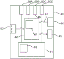
FIG. 2 illustrates a peripheral device according to one embodiment of the present invention.
The peripheral device 40 includes four terminals 50A, 50B, 50C, 50D (which may be provided in the form of a USB plug (see fig. 3)).
Two of the terminals 50B, 50C are coupled to the light controller 42 having the function of the communication unit and the function of the control unit. The other two terminals 50A, 50D are coupled to a power unit 41, the power unit 41 processing the operating power of the peripheral device 40.
The peripheral device 40 also includes a sensor 44 coupled to the light controller 42 via a sensor line 43. Additionally, the light controller 42 interacts with a communication interface 45 of the light controller 40 that provides wireless communication.
Still further, the peripheral device includes a switch 63 having three settings that is also coupled to the light controller 42.
The light controller 42 includes a detection unit 61, and the power unit 41 includes a reception unit 62.
In the first mode, the peripheral device 40 operates as a USB slave device when connected to a USB host (see fig. 3). The light controller 42 (communication unit) communicates with the USB host according to the USB protocol via the terminals 50B, 50C. The power unit 41 receives operating power of the peripheral device from the USB host.
In the second mode, the peripheral device 40 controls the controlled device (see fig. 3). Here, the light controller 42 functions as a control unit, provides a control signal to the controlled device via the terminals 50B, 50C, and the power unit 41 receives operating power from the controlled device.
The detection unit 61 is provided for switching between the first mode and the second mode depending on whether the peripheral device 40 is coupled to the controlled device or the host. Additionally, using the switch 63, the switch 63 covers (overrides) the detection by the detection unit in two of its three settings. One setting fixes the first mode, another sets the second mode, and the third setting allows the detection by the detection unit 61 to be decisive.
In at least the second mode, the receiving unit 62 of the power unit monitors the operating power provided by the controlled device and derives therefrom the information transmitted from the controlled device.
The light controller 42 uses information provided from the sensor 44 and/or the communication interface 45 to determine control of the controlled device.
Fig. 3 illustrates a system including a peripheral device, a controlled device, and a host according to another embodiment of the present invention.
The system 1 includes a peripheral device 40, a controlled device 20, and a host 70.
The peripheral device 40 is arranged to be connected to a data terminal (V)busAnd ground) of the USB compatible plug 50, where V isbusDeliver + 5V relative to ground. Two data pins are used for control signals and instead of using the typical phy and uPnP techniques of USB, simpler information and signal transmission techniques are used in the mode in which the controlled device is controlled.
In this embodiment, the peripheral generates a tone that is placed on the data pin (first pair of terminals)A light PWM signal (46). The PWM signal 46 is sent over the Data + pin 47. To ensure that any "normal" USB host will not recognize the peripheral device as a USB device in this mode, the Data pin Data-48 is pulled up to V by means of resistor 49bus。
The peripheral device 40 includes a light controller 42, the light controller 42 controlling the dimming level from 75% to 30% using, for example, an external signal 43 from a presence detector when no person is detected.
The entire circuitry of the peripheral device may be mounted on a PCB (not shown) that fits directly into a USB socket (see 34, 71) such as a conventional USB stick.
The controlled device 20 comprises an illumination means 30, the illumination means 30 being driven by a driver 32, the driver 32 being powered by the mains 10. The driver 32 is also coupled to the socket 34 with four lines 35. In the circuit of line 35, two resistors 36, 37 are provided between the data line and ground.
The host 70 is a conventional PC and further comprises a USB socket 71. In addition to PWM control, more sophisticated communications from peripheral device 40 to luminaire 20 may also be used in other implementations. For example, it is contemplated that the I2C signal is placed on two data pins of a connector, thus allowing multiple parameters to be transmitted and allowing for more complex control techniques.
Alternatively, a differential DALI signal may be placed on the data pins and a normal DALI lamp driver may be controlled.
In another embodiment, UART signaling is used, where instead of differential signaling (D +, D-) as in standard USB, the interface is mapped to a receive/transmit (RX, TX) signal pair. Such a signaling scheme is available in many low-cost microprocessors (with small RAM and flash memory sizes), allowing bi-directional data flow: commands to the driver of the controlled device and data to the peripheral device. In such a case, PWM control of dimming the light may be generated by the MCU in the driver as a response to the command.
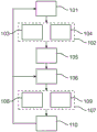
FIG. 4 shows a flow diagram illustrating a method including communication between a host and a peripheral device and control of a controlled device by the peripheral device, according to one embodiment of the present invention. The methods discussed herein are applicable, for example, to the system shown in fig. 3.
In the flow chart shown in fig. 4, the process starts with a first coupling step 101 of coupling the peripheral device and the host.
The communication step 102 follows. The communication step 102 includes a first power receiving step 103 in which the peripheral device receives operating power from the host via a second pair of terminals of the plurality of terminals of the peripheral device, in the first power receiving step 103. In this case, the peripheral device operates in a first mode, and the communicating step 102 further comprises a first operating step 104 of communicating between the peripheral device and the host according to a predetermined criterion via a first pair of terminals of the plurality of terminals.
After the communication step 102, a first separation step 105 of separating the peripheral device and the host follows.
This is in turn followed by a second coupling step 106 of coupling the peripheral device and the controlled device.
In one specific implementation, the coupling in the first and second coupling steps 101, 106, respectively, is provided by connecting a USB plug of the peripheral device to a corresponding USB socket of the host or controlled device.
After the coupling between the controlled device and the peripheral device, a control step 107 follows, in which the peripheral device receives operating power from the controlled device via the second pair of terminals in a second power receiving step 108. Further, the peripheral device now operates in a second mode comprising a second operation step in which a controlled device control via at least two of the first and second pairs of terminals is provided, the control being unrelated to operating power.
Finally, the coupling between the controlled device and the peripheral device is ended in a second separation step 110, so that the peripheral device can be coupled to the host (or another host or another controlled device) again.
The peripheral device does not necessarily have to be connected to the host first (e.g., for configuration) because the peripheral device can be commissioned during manufacture, although field configuration (initial or later) is still possible. Adding network functionality to existing lighting systems requires commissioning steps that ensure proper binding of physical luminaires with their representation in the network.
While the invention has been illustrated and described in detail in the drawings and foregoing description, such illustration and description are to be considered illustrative or exemplary and not restrictive; the invention is not limited to the disclosed embodiments.
Other variations to the disclosed embodiments can be understood and effected by those skilled in the art in practicing the claimed invention, from a study of the drawings, the disclosure, and the appended claims.
For example, it is possible to operate the invention in embodiments where the controlled device is a different device than (the operating device of) the luminaire, as the invention is not limited to the specific details of the controlled device.
For example, the present invention allows for the alternative use of a USB port (i.e., the physical configuration of the receptacle) that allows for the majority of the cost to be placed on the side of the USB module and not on the side of the controlled device. In this way, the USB port can be used as a cost-neutral (cost-neutral) addition to the lamp driver. Proper definition of the purpose of the pins of the USB port ensures that if a peripheral module is connected (e.g., in the wrong mode), the "normal" USB host will not be compromised. In the non-USB mode of the peripheral device, the USB host will typically not be able to identify the device and make full use of these modules. Vice versa, when inserted into a luminaire having a reverse USB architecture (as one example of a controlled device), the USB module will not be compromised, but such USB module will not have accessible functionality (other than the supply of USB power).
The benefit is a much simpler interface on the luminaire side. The peripheral device (e.g., USB module) gets power from the USB connector as is known from USB of the current art. The peripheral device may use, for example, a PWM signal on a data pin that directly controls the PWM input of a lamp driver in the luminaire (as one example of a controlled device).
The present invention provides interchangeability of the control device compared to the arrangement of fig. 1. Such interchangeability allows for easy upgrade of the illuminator (or other system in which the present invention is employed) and easy configuration of the platform with the application-related control device. This is done by placing the control device in a module which is mechanically and electrically connected by means of a socket/plug arrangement. However, the present invention not only provides interchangeability, as the peripheral device uses the same physical features of the plug for communicating with the host. Such a host (e.g., a computer) may configure the peripheral based on such communication according to, for example, the USB standard.
Implementations of the invention may be categorized into different classes, for example:
class A: the luminaire (or other device) provides power only to the peripheral device without providing additional functionality.
Class B1: the controlled device supports power for the peripheral device and accepts the analog dimming signal (e.g., via a data pin of the USB port).
Class B2: the controlled device supports power for the peripheral and allows PWM dimming (e.g., via the data pin of the USB port).
Class C: the controlled device supports power and bi-directional communication (e.g., according to I2C) for peripheral devices (e.g., via data pins of a USB port), and such an implementation is particularly advantageous for digital drivers with built-in microcontrollers.
In case the luminaire is a controlled device, the control signals provided by the peripheral devices (in case of class B) can be shared between different light engines (e.g. LED modules), wherein the light engines are controlled in the same way, while the addressing capability of e.g. the I2C bus in class C will allow to control the light engines in the luminaire even individually.
The peripheral device may be able to distinguish different lamp drivers (or generally controlled devices) to adapt the control signals on the (data) pins accordingly, e.g. by means of signature impedance (signature) or by configuration via an NFC interface. This allows the same peripheral device to be used for different controlled devices, automatically changing for example from PWM to I2C or DALI depending on the identified driver.
It is also contemplated that the managed "USB" power distribution may be used to ensure that incompatible USB devices do not draw power from the controlled device.
A simple interface is used to verify whether a plug-in device is allowed to communicate to the drive according to the invention and to interrupt power if the device is not a compatible device.
In one implementation, the verification process begins by checking whether the device is connected to a "USB" port via sensing the current drawn. After this, the driver of the controlled device checks for a special signature from the peripheral device that should come within a predefined interval from the moment the port connection is detected.
Another way of verifying is by checking whether the reply to the challenge produces a correct response.
The power disconnection may be accomplished by disabling the power regulator or disconnecting the "USB" power line using a power switch. The power reconnect may be achieved by checking whether the current drawn from the port has dropped below a certain threshold.
Instead of digital control methods, analog control techniques may also be used. For example, it is possible to use the voltage (reference GND pin) on one or two digital signal pins Data + (UPIN 2) and Data- (UPIN 3) for the signaling voltage. To this end, advantageously, the signal used to linearly control the driver is in the forbidden range of digital signals (e.g., 0.7V to 3.7V) and will be undefined for digital input.
It may for example be used to signal in such a way: UPIN2=0.7V means 0% light intensity (lamp off); UPIN2=1.7V means a light intensity of 33%; UPIN2=2.7V means 66% light intensity, and UPIN2=3.7V means 100% light intensity (lamp fully on). Such a mapping has the following benefits: a low level will keep the lamp off and a high level will set it to be fully on.
A resistor on the lamp driver side UPIN2 can be used to ensure that the voltage UPIN2 is above 3.7V if no peripheral device is connected, and thus the driver will always be fully on.
Different mappings of the voltages UPIN2 and UPIN3 to lamp control are possible. For example, these can be extended by exceeding the dimming levels for the colors listed above, or the color temperature can also be defined.
Even if the interface is not isolated, for example for size or cost reasons, it is assumed that the interface is mains-isolated to cope with safety standards. In such a case, it may be advantageous to derive only auxiliary power for the USB in an isolated manner.
This can be done more cost effectively by means of a pair of small Y capacitors (e.g., 10 to 100 pF) of connected drain and source (or collector and emitter) of the chopper of the driver or the switching transistor (or one) of the inverter, in addition to the conventional approach of using an isolation transformer. The concept applies to substantially all SMPS transformer types including single switch buck, boost, buck-boost and flyback.
Second, the setpoint signal(s) (e.g., PWM dimming pattern) received from the USB host or locally derived signals may be sent to the feedback controller of the driver in an isolated manner, e.g., via a light coupler.
It may be useful to provide a return channel from the controlled device to the peripheral device, e.g. for transmitting faults, type of drive or any address data (if present), configuration data, etc. Further, it is beneficial to send a measured control value (e.g., output current) or control error.
One method for implementing such a return channel-without utilizing the USB data pin-is referred to as capacitive powering as mentioned above. A small additional transistor (e.g., between ground and the second Y capacitor) may periodically interrupt auxiliary power transfer, which in conjunction with a filter on the isolation terminal causes modulation of the 5V supply that may be sensed by the peripheral. For driver-side simplicity, for example, the interrupt pulse width that controls the modulation amplitude (e.g., 50 … 500 mV 500) added to the 5V supply may be modulated. An interrupt frequency (e.g., 1Hz … 10 Hz) may also or additionally be used.
Examples of functionality that a peripheral device according to the present invention may bring to a controlled device (e.g., a luminaire) include (but are not limited to): wireless range extenders such as for WiFi, wireless bridges such as between WiFi and ZigBee; a sensing function for local control of the LED driver, a sensing and connection function as part of a sensor network, a control function enabling connectivity, a control and data retrieval function enabling connectivity, an IR receiver for luminaire control, a wireless speaker, a low bit rate (event based) wireless (e.g. WiFi) access point, utilization of network connectivity (which may be used to support a sensing function with a low data rate output), a wireless low power camera module; upgrade kit for converting a simple analog driver to a digital driver and wireless CodedLight module for upgrading an existing luminaire driver to enable a CodedLight driver.
In the claims, the word "comprising" does not exclude other elements or steps, and the indefinite article "a" or "an" does not exclude a plurality.
A single processor, device or other unit may fulfill the functions of several items recited in the claims. The mere fact that certain measures are recited in mutually different dependent claims does not indicate that a combination of these measures cannot be used to advantage.
Operations like communication, control, output, mode switching, detection, sensing, coupling, etc. may be implemented as program code means of a computer program and/or as dedicated hardware.
A computer program may be stored/distributed on a suitable medium, such as an optical storage medium or a solid-state medium supplied together with or as part of other hardware, but may also be distributed in other forms, such as via the internet or other wired or wireless telecommunication systems.
Any reference signs in the claims shall not be construed as limiting the scope.
Claims (13)
1. A peripheral device (40) for communicating with a host (70) and for controlling a controlled device (20), comprising:
a plurality of terminals (50, 50A-D) including a first pair of terminals and a second pair of terminals (50A, 50D),
a communication unit coupled to the first pair of terminals (50B, 50C),
a control unit coupled to at least two terminals of the first and second pairs of terminals (50, 50A-D),
a detection unit (61) arranged to detect whether the peripheral device (40) is connected to the host (70) or to the controlled device (20),
wherein the peripheral device (40) is arranged to receive operating power via the second pair of terminals (50A, 50D),
wherein the peripheral device (40) is further arranged to selectively operate in at least a first mode and a second mode,
-the first mode is a mode in which the communication unit is operable to communicate with the host (70) according to a predetermined criterion and the peripheral device (40) is arranged to receive the operating power from the host (70), and
-the second mode is a mode in which the control unit is operable to control the controlled device (20), the control is not related to the operating power and the peripheral device (40) is arranged to receive the operating power from the controlled device (20),
wherein the detection unit (61) is arranged to control the peripheral device (40) to switch between the first and second modes based on the detection result.
2. The peripheral device (40) according to claim 1, wherein the control unit is arranged to output one of an analog signal, a pulse width modulated signal and a digital signal to the controlled device via the at least two terminals.
3. The peripheral device (40) of claim 1, comprising:
a switch (63) for operating the peripheral device in the first mode when the switch (63) is in a first state, and for operating the peripheral device in the second mode when the switch (63) is in a second state; wherein
The detection unit (61) is arranged to detect whether the peripheral device (40) is connected to the host (70) or to the controlled device (20), wherein the detection unit (61) is arranged to control the peripheral device (40) for mode switching to the first or second mode based on the detection result when the switch (63) is in a third state.
4. The peripheral device (40) of claim 1, comprising:
a sensor (44) and/or a communication interface (45) coupled to the control unit, wherein the control unit is arranged for controlling the controlled device (20) in dependence of input from the sensor (44) and/or the communication interface (45).
5. The peripheral device (40) according to claim 1, wherein the predetermined standard is a USB standard or an IEEE 1394 standard.
6. The peripheral device (40) of claim 1, comprising:
a receiving unit (62) coupled to the plurality of terminals (50, 50A-D), wherein the receiving unit (62) is arranged to receive information transmitted by the controlled device (20) via the plurality of terminals (50, 50A-D).
7. The peripheral device (40) according to claim 6, wherein the receiving unit (62) is coupled to the second pair of terminals (50A, 50D) and arranged to detect transmission information according to a change in supplied operating power.
8. A system (1) comprising a peripheral device (40) according to claim 1 and a controlled device (20),
wherein the controlled device (20) comprises: a plurality of device terminals (34) for coupling to the plurality of terminals (50, 50A-50D) of the peripheral device (40), a power supply unit for supplying operating power to the peripheral device (40) via the second pair of terminals (50A, 50D), and operating circuitry for coupling to the control unit of the peripheral device (40) and controlled by the control unit of the peripheral device (40).
9. The system (1) according to claim 8, further comprising: a host (70) arranged for communicating with the peripheral device (40) according to the predetermined criterion.
10. The system (1) as defined in claim 8, wherein the peripheral device (40) and the controlled device (20) jointly comprise operating circuitry for operating an operating unit (30) of the controlled device (20), wherein a first part (42, 47, 48) of the operating circuitry is provided in the peripheral device (40) and a second part of the operating circuitry is provided in the controlled device (20).
11. The system (1) according to claim 8, wherein the controlled device (20) is a luminaire.
12. A method comprising communication between a host (70) and a peripheral device (40) and control of a controlled device (20) by the peripheral device (40), the method comprising:
-a first coupling step (101) of coupling the peripheral device (40) and the host (70),
-detecting, via a detection unit (61), that the peripheral device (40) is connected to the host (70),
-a communication step (102), wherein the peripheral device (40) receives (103) operating power from the host (70) via a second pair of terminals (50A, 50D) of a plurality of terminals (50, 50A-50D) of the peripheral device (40) and operates in a first mode comprising communication (104) between the peripheral device (40) and the host (70) via a first pair of terminals of the plurality of terminals (50, 50A-50D) according to a predetermined criterion,
-a separation step (105) of separating the peripheral device (40) and the host (70),
-a second coupling step (106) of coupling the peripheral device (40) and the controlled device (20),
-detecting, via the detection unit (61), that the peripheral device (40) is connected to the controlled device (20), and
-a control step, in which the peripheral device (40) receives operating power from the controlled device (20) via the second pair of terminals (50A, 50D), and operates in a second mode comprising a control (109) of the controlled device (20) via at least two terminals of the first and second pairs of terminals (50, 50A-D), the control being unrelated to the operating power.
13. A computer-readable storage medium for a peripheral device (40) having embodied thereon a computer program product comprising code for causing a peripheral device (40) as defined in claim 1 to carry out the steps of the method as defined in claim 12 when the code is run on the peripheral device (40).
Applications Claiming Priority (3)
| Application Number | Priority Date | Filing Date | Title |
|---|---|---|---|
| EP16152902 | 2016-01-27 | ||
| EP16152902.9 | 2016-01-27 | ||
| PCT/EP2017/051312 WO2017129517A1 (en) | 2016-01-27 | 2017-01-23 | Peripheral device, system including the peripheral device and method |
Publications (2)
| Publication Number | Publication Date |
|---|---|
| CN108702830A CN108702830A (en) | 2018-10-23 |
| CN108702830B true CN108702830B (en) | 2021-07-13 |
Family
ID=55262721
Family Applications (1)
| Application Number | Title | Priority Date | Filing Date |
|---|---|---|---|
| CN201780008909.3A Active CN108702830B (en) | 2016-01-27 | 2017-01-23 | Peripheral device, system including peripheral device and method |
Country Status (5)
| Country | Link |
|---|---|
| US (1) | US11397693B2 (en) |
| EP (1) | EP3409080B1 (en) |
| JP (1) | JP6779999B2 (en) |
| CN (1) | CN108702830B (en) |
| WO (1) | WO2017129517A1 (en) |
Families Citing this family (2)
| Publication number | Priority date | Publication date | Assignee | Title |
|---|---|---|---|---|
| US10320180B1 (en) * | 2018-04-24 | 2019-06-11 | Cypress Semiconductor Corporation | Current control and protection for universal serial bus type-C (USB-C) connector systems |
| CN114034979A (en) * | 2021-11-12 | 2022-02-11 | 昆明理工大学 | Alternating current transmission line distance measuring method and system |
Citations (2)
| Publication number | Priority date | Publication date | Assignee | Title |
|---|---|---|---|---|
| CN101021822A (en) * | 2007-03-13 | 2007-08-22 | 威盛电子股份有限公司 | USB peripheral equipment and mode detecting method thereof |
| CN104021101A (en) * | 2014-05-09 | 2014-09-03 | 深圳市汇川控制技术有限公司 | USB interface system and implementation method based on LPC1768 platform |
Family Cites Families (28)
| Publication number | Priority date | Publication date | Assignee | Title |
|---|---|---|---|---|
| US6357011B2 (en) | 1998-07-15 | 2002-03-12 | Gateway, Inc. | Bus-powered computer peripheral with supplement battery power to overcome bus-power limit |
| US6804727B1 (en) * | 2001-02-23 | 2004-10-12 | Lexmark International, Inc. | Method for communication from a host computer to a peripheral device |
| GB2375273B (en) | 2001-04-30 | 2004-07-07 | Nokia Mobile Phones Ltd | Communication interface for an electronic device |
| JP2002366284A (en) * | 2001-06-08 | 2002-12-20 | Alps Electric Co Ltd | Keyboard device for portable electronic equipment and charging equipment |
| US7126585B2 (en) | 2001-08-17 | 2006-10-24 | Jeffery Davis | One chip USB optical mouse sensor solution |
| KR100444702B1 (en) * | 2002-04-18 | 2004-08-16 | 삼성전자주식회사 | Dsl modem supporting high-speed usb interface |
| US6732218B2 (en) * | 2002-07-26 | 2004-05-04 | Motorola, Inc. | Dual-role compatible USB hub device and method |
| WO2004086363A2 (en) * | 2003-03-27 | 2004-10-07 | M-Systems Flash Disk Pioneers Ltd. | Data storage device with full access by all users |
| US7441053B2 (en) * | 2003-12-15 | 2008-10-21 | Nokia Corporation | Support of an interaction between a host device and a peripheral device |
| US8469808B2 (en) | 2004-01-15 | 2013-06-25 | Bgc Partners, Inc. | System and method for managing a game controller device for electronic trading |
| US20050170699A1 (en) * | 2004-02-03 | 2005-08-04 | Overtoom Eric J. | USB OTG adapter module for debugging USB OTG devices |
| TW200513865A (en) | 2004-09-17 | 2005-04-16 | Via Tech Inc | USB control circuit with function of switching between host mode and controlled mode and its operating method |
| KR101329307B1 (en) | 2007-01-25 | 2013-11-13 | 삼성전자주식회사 | Apparatus and method for controlling USB operation |
| US7717607B2 (en) * | 2007-10-30 | 2010-05-18 | General Dynamics Itronix Corporation | System and apparatus for keyboard illumination |
| US8296486B2 (en) | 2008-03-17 | 2012-10-23 | International Business Machines Corporation | Peripheral device enabling enhanced communication |
| US8421779B2 (en) | 2008-05-29 | 2013-04-16 | Himax Technologies Limited | Display and method thereof for signal transmission |
| US9208118B2 (en) * | 2008-06-10 | 2015-12-08 | Lg Electronics Inc. | Communication device, a method of processing signal in the communication device and a system having the communication device |
| US8330586B2 (en) | 2009-02-24 | 2012-12-11 | Marvell World Trade Ltd. | Systems and methods for programming of a cooling fan via a serial port communication mode |
| US20130191568A1 (en) | 2012-01-23 | 2013-07-25 | Qualcomm Incorporated | Operating m-phy based communications over universal serial bus (usb) interface, and related cables, connectors, systems and methods |
| US10219338B2 (en) * | 2012-07-01 | 2019-02-26 | Cree, Inc. | Modular lighting control |
| CN202791496U (en) | 2012-09-06 | 2013-03-13 | 昆明理工大学 | Dimmable universal serial bus (USB) lamp |
| US8909815B2 (en) * | 2012-11-07 | 2014-12-09 | Analogix Semiconductor, Inc. | Devices and methods for multiple data streams over USB 2.0 |
| KR101999660B1 (en) | 2012-11-08 | 2019-10-01 | 엘지이노텍 주식회사 | The lighting apparatus having the communication module |
| JP6377075B2 (en) * | 2012-12-18 | 2018-08-22 | クリー インコーポレイテッドCree Inc. | Lighting fixture for distributed control |
| US9244876B2 (en) * | 2012-12-20 | 2016-01-26 | Blackberry Limited | Method and apparatus pertaining to universal serial bus-based charging |
| CN103309308B (en) * | 2013-05-17 | 2016-08-10 | 华为技术有限公司 | A kind of device intelligence control method and device, system, PnP device |
| US9460037B2 (en) * | 2013-09-26 | 2016-10-04 | Delphi Technologies, Inc. | Flexible mobile device connectivity to automotive systems with USB hubs |
| JP2015095420A (en) * | 2013-11-13 | 2015-05-18 | パナソニックIpマネジメント株式会社 | Illumination control device and illumination system |
-
2017
- 2017-01-23 US US16/069,513 patent/US11397693B2/en active Active
- 2017-01-23 CN CN201780008909.3A patent/CN108702830B/en active Active
- 2017-01-23 WO PCT/EP2017/051312 patent/WO2017129517A1/en unknown
- 2017-01-23 JP JP2018531160A patent/JP6779999B2/en active Active
- 2017-01-23 EP EP17701684.7A patent/EP3409080B1/en active Active
Patent Citations (2)
| Publication number | Priority date | Publication date | Assignee | Title |
|---|---|---|---|---|
| CN101021822A (en) * | 2007-03-13 | 2007-08-22 | 威盛电子股份有限公司 | USB peripheral equipment and mode detecting method thereof |
| CN104021101A (en) * | 2014-05-09 | 2014-09-03 | 深圳市汇川控制技术有限公司 | USB interface system and implementation method based on LPC1768 platform |
Also Published As
| Publication number | Publication date |
|---|---|
| JP2019509582A (en) | 2019-04-04 |
| JP6779999B2 (en) | 2020-11-04 |
| EP3409080B1 (en) | 2019-08-21 |
| CN108702830A (en) | 2018-10-23 |
| EP3409080A1 (en) | 2018-12-05 |
| US20190012277A1 (en) | 2019-01-10 |
| US11397693B2 (en) | 2022-07-26 |
| WO2017129517A1 (en) | 2017-08-03 |
Similar Documents
| Publication | Publication Date | Title |
|---|---|---|
| US10694609B2 (en) | Wireless lighting control | |
| CN107148806B (en) | Apparatus, method and system for controlling a load device via a power line using a power negotiation protocol | |
| US8626318B2 (en) | Lamp device | |
| CN106465500B (en) | improved communication module | |
| US10561007B2 (en) | Inline wireless module | |
| US9356460B2 (en) | Method and apparatus of fast battery charging with universal high power input source | |
| CN109644533B (en) | Driver system for a light emitting device | |
| JP5383924B2 (en) | Method for controlling operation of electronic converter, corresponding electronic converter, lighting system and software product | |
| US9746138B1 (en) | Modular lighting and ancillary component apparatus and system | |
| CN107990221B (en) | Combined lamp and illumination system | |
| CN107994926A (en) | A kind of circuit and communication system that signal transmission is realized based on power carrier | |
| KR102069708B1 (en) | Accessory Device for supporting a hierarchical connection and System, and Supporting Method thereof | |
| CN108702830B (en) | Peripheral device, system including peripheral device and method | |
| WO2017129490A1 (en) | System and method for modular control | |
| AU2008355732A1 (en) | System and method for efficient association of a power outlet and device | |
| US20080157697A1 (en) | Apparatus for controlling lamp source and electric equipment and power socket therof | |
| CN104995802B (en) | Communication module adapter | |
| JP2009508411A (en) | System for monitoring cable interface connections in a network | |
| CN105633942A (en) | Low-voltage DC household intelligent power supply system | |
| CN203482464U (en) | LED lamp communication control bridge | |
| CN218974908U (en) | Wireless downloader suitable for Arduino | |
| CN209643046U (en) | A kind of DALI controller for supporting scene to extend | |
| CN104953394A (en) | Wireless intelligent socket and implementation method therefor | |
| CN103491686B (en) | A kind of LED lamp Control on Communication bridger and debugging collocation method thereof |
Legal Events
| Date | Code | Title | Description |
|---|---|---|---|
| PB01 | Publication | ||
| PB01 | Publication | ||
| SE01 | Entry into force of request for substantive examination | ||
| SE01 | Entry into force of request for substantive examination | ||
| CB02 | Change of applicant information | ||
| CB02 | Change of applicant information |
Address after: Eindhoven, the Netherlands Applicant after: Signify Holdings Ltd. Address before: Eindhoven, the Netherlands Applicant before: PHILIPS LIGHTING HOLDING B.V. |
|
| GR01 | Patent grant | ||
| GR01 | Patent grant |