CN108702199B - Apparatus and method for supporting unified wireless backhaul and access network in wireless communication system - Google Patents
Apparatus and method for supporting unified wireless backhaul and access network in wireless communication system Download PDFInfo
- Publication number
- CN108702199B CN108702199B CN201780011334.0A CN201780011334A CN108702199B CN 108702199 B CN108702199 B CN 108702199B CN 201780011334 A CN201780011334 A CN 201780011334A CN 108702199 B CN108702199 B CN 108702199B
- Authority
- CN
- China
- Prior art keywords
- time
- transmission over
- abs
- backhaul
- wireless backhaul
- Prior art date
- Legal status (The legal status is an assumption and is not a legal conclusion. Google has not performed a legal analysis and makes no representation as to the accuracy of the status listed.)
- Active
Links
Images


Classifications
-
- H—ELECTRICITY
- H04—ELECTRIC COMMUNICATION TECHNIQUE
- H04B—TRANSMISSION
- H04B7/00—Radio transmission systems, i.e. using radiation field
- H04B7/14—Relay systems
- H04B7/15—Active relay systems
- H04B7/155—Ground-based stations
-
- H—ELECTRICITY
- H04—ELECTRIC COMMUNICATION TECHNIQUE
- H04B—TRANSMISSION
- H04B7/00—Radio transmission systems, i.e. using radiation field
- H04B7/14—Relay systems
- H04B7/15—Active relay systems
- H04B7/155—Ground-based stations
- H04B7/15528—Control of operation parameters of a relay station to exploit the physical medium
- H04B7/15542—Selecting at relay station its transmit and receive resources
-
- H—ELECTRICITY
- H04—ELECTRIC COMMUNICATION TECHNIQUE
- H04W—WIRELESS COMMUNICATION NETWORKS
- H04W72/00—Local resource management
- H04W72/20—Control channels or signalling for resource management
-
- H—ELECTRICITY
- H04—ELECTRIC COMMUNICATION TECHNIQUE
- H04B—TRANSMISSION
- H04B7/00—Radio transmission systems, i.e. using radiation field
- H04B7/14—Relay systems
- H04B7/15—Active relay systems
- H04B7/155—Ground-based stations
- H04B7/15507—Relay station based processing for cell extension or control of coverage area
-
- H—ELECTRICITY
- H04—ELECTRIC COMMUNICATION TECHNIQUE
- H04B—TRANSMISSION
- H04B7/00—Radio transmission systems, i.e. using radiation field
- H04B7/14—Relay systems
- H04B7/15—Active relay systems
- H04B7/155—Ground-based stations
- H04B7/15528—Control of operation parameters of a relay station to exploit the physical medium
-
- H—ELECTRICITY
- H04—ELECTRIC COMMUNICATION TECHNIQUE
- H04B—TRANSMISSION
- H04B7/00—Radio transmission systems, i.e. using radiation field
- H04B7/24—Radio transmission systems, i.e. using radiation field for communication between two or more posts
- H04B7/26—Radio transmission systems, i.e. using radiation field for communication between two or more posts at least one of which is mobile
- H04B7/2603—Arrangements for wireless physical layer control
- H04B7/2606—Arrangements for base station coverage control, e.g. by using relays in tunnels
-
- H—ELECTRICITY
- H04—ELECTRIC COMMUNICATION TECHNIQUE
- H04B—TRANSMISSION
- H04B7/00—Radio transmission systems, i.e. using radiation field
- H04B7/24—Radio transmission systems, i.e. using radiation field for communication between two or more posts
- H04B7/26—Radio transmission systems, i.e. using radiation field for communication between two or more posts at least one of which is mobile
- H04B7/2643—Radio transmission systems, i.e. using radiation field for communication between two or more posts at least one of which is mobile using time-division multiple access [TDMA]
-
- H—ELECTRICITY
- H04—ELECTRIC COMMUNICATION TECHNIQUE
- H04L—TRANSMISSION OF DIGITAL INFORMATION, e.g. TELEGRAPHIC COMMUNICATION
- H04L1/00—Arrangements for detecting or preventing errors in the information received
-
- H—ELECTRICITY
- H04—ELECTRIC COMMUNICATION TECHNIQUE
- H04L—TRANSMISSION OF DIGITAL INFORMATION, e.g. TELEGRAPHIC COMMUNICATION
- H04L27/00—Modulated-carrier systems
- H04L27/26—Systems using multi-frequency codes
-
- H—ELECTRICITY
- H04—ELECTRIC COMMUNICATION TECHNIQUE
- H04L—TRANSMISSION OF DIGITAL INFORMATION, e.g. TELEGRAPHIC COMMUNICATION
- H04L5/00—Arrangements affording multiple use of the transmission path
- H04L5/003—Arrangements for allocating sub-channels of the transmission path
- H04L5/0032—Distributed allocation, i.e. involving a plurality of allocating devices, each making partial allocation
-
- H—ELECTRICITY
- H04—ELECTRIC COMMUNICATION TECHNIQUE
- H04L—TRANSMISSION OF DIGITAL INFORMATION, e.g. TELEGRAPHIC COMMUNICATION
- H04L5/00—Arrangements affording multiple use of the transmission path
- H04L5/003—Arrangements for allocating sub-channels of the transmission path
- H04L5/0053—Allocation of signaling, i.e. of overhead other than pilot signals
- H04L5/0055—Physical resource allocation for ACK/NACK
-
- H—ELECTRICITY
- H04—ELECTRIC COMMUNICATION TECHNIQUE
- H04L—TRANSMISSION OF DIGITAL INFORMATION, e.g. TELEGRAPHIC COMMUNICATION
- H04L5/00—Arrangements affording multiple use of the transmission path
- H04L5/003—Arrangements for allocating sub-channels of the transmission path
- H04L5/0078—Timing of allocation
- H04L5/0082—Timing of allocation at predetermined intervals
-
- H—ELECTRICITY
- H04—ELECTRIC COMMUNICATION TECHNIQUE
- H04L—TRANSMISSION OF DIGITAL INFORMATION, e.g. TELEGRAPHIC COMMUNICATION
- H04L5/00—Arrangements affording multiple use of the transmission path
- H04L5/0091—Signaling for the administration of the divided path
- H04L5/0092—Indication of how the channel is divided
-
- H—ELECTRICITY
- H04—ELECTRIC COMMUNICATION TECHNIQUE
- H04L—TRANSMISSION OF DIGITAL INFORMATION, e.g. TELEGRAPHIC COMMUNICATION
- H04L5/00—Arrangements affording multiple use of the transmission path
- H04L5/14—Two-way operation using the same type of signal, i.e. duplex
- H04L5/143—Two-way operation using the same type of signal, i.e. duplex for modulated signals
-
- H—ELECTRICITY
- H04—ELECTRIC COMMUNICATION TECHNIQUE
- H04L—TRANSMISSION OF DIGITAL INFORMATION, e.g. TELEGRAPHIC COMMUNICATION
- H04L5/00—Arrangements affording multiple use of the transmission path
- H04L5/14—Two-way operation using the same type of signal, i.e. duplex
- H04L5/16—Half-duplex systems; Simplex/duplex switching; Transmission of break signals non-automatically inverting the direction of transmission
-
- H—ELECTRICITY
- H04—ELECTRIC COMMUNICATION TECHNIQUE
- H04W—WIRELESS COMMUNICATION NETWORKS
- H04W40/00—Communication routing or communication path finding
- H04W40/02—Communication route or path selection, e.g. power-based or shortest path routing
- H04W40/22—Communication route or path selection, e.g. power-based or shortest path routing using selective relaying for reaching a BTS [Base Transceiver Station] or an access point
-
- H—ELECTRICITY
- H04—ELECTRIC COMMUNICATION TECHNIQUE
- H04W—WIRELESS COMMUNICATION NETWORKS
- H04W56/00—Synchronisation arrangements
-
- H—ELECTRICITY
- H04—ELECTRIC COMMUNICATION TECHNIQUE
- H04W—WIRELESS COMMUNICATION NETWORKS
- H04W72/00—Local resource management
- H04W72/20—Control channels or signalling for resource management
- H04W72/23—Control channels or signalling for resource management in the downlink direction of a wireless link, i.e. towards a terminal
-
- H—ELECTRICITY
- H04—ELECTRIC COMMUNICATION TECHNIQUE
- H04L—TRANSMISSION OF DIGITAL INFORMATION, e.g. TELEGRAPHIC COMMUNICATION
- H04L1/00—Arrangements for detecting or preventing errors in the information received
- H04L1/12—Arrangements for detecting or preventing errors in the information received by using return channel
- H04L1/16—Arrangements for detecting or preventing errors in the information received by using return channel in which the return channel carries supervisory signals, e.g. repetition request signals
- H04L1/1607—Details of the supervisory signal
- H04L1/1671—Details of the supervisory signal the supervisory signal being transmitted together with control information
-
- H—ELECTRICITY
- H04—ELECTRIC COMMUNICATION TECHNIQUE
- H04L—TRANSMISSION OF DIGITAL INFORMATION, e.g. TELEGRAPHIC COMMUNICATION
- H04L5/00—Arrangements affording multiple use of the transmission path
- H04L5/0001—Arrangements for dividing the transmission path
- H04L5/0003—Two-dimensional division
- H04L5/0005—Time-frequency
- H04L5/0007—Time-frequency the frequencies being orthogonal, e.g. OFDM(A), DMT
- H04L5/001—Time-frequency the frequencies being orthogonal, e.g. OFDM(A), DMT the frequencies being arranged in component carriers
-
- H—ELECTRICITY
- H04—ELECTRIC COMMUNICATION TECHNIQUE
- H04L—TRANSMISSION OF DIGITAL INFORMATION, e.g. TELEGRAPHIC COMMUNICATION
- H04L5/00—Arrangements affording multiple use of the transmission path
- H04L5/0001—Arrangements for dividing the transmission path
- H04L5/0014—Three-dimensional division
- H04L5/0023—Time-frequency-space
-
- H—ELECTRICITY
- H04—ELECTRIC COMMUNICATION TECHNIQUE
- H04W—WIRELESS COMMUNICATION NETWORKS
- H04W84/00—Network topologies
- H04W84/02—Hierarchically pre-organised networks, e.g. paging networks, cellular networks, WLAN [Wireless Local Area Network] or WLL [Wireless Local Loop]
- H04W84/04—Large scale networks; Deep hierarchical networks
- H04W84/042—Public Land Mobile systems, e.g. cellular systems
- H04W84/047—Public Land Mobile systems, e.g. cellular systems using dedicated repeater stations
-
- H—ELECTRICITY
- H04—ELECTRIC COMMUNICATION TECHNIQUE
- H04W—WIRELESS COMMUNICATION NETWORKS
- H04W88/00—Devices specially adapted for wireless communication networks, e.g. terminals, base stations or access point devices
- H04W88/02—Terminal devices
-
- H—ELECTRICITY
- H04—ELECTRIC COMMUNICATION TECHNIQUE
- H04W—WIRELESS COMMUNICATION NETWORKS
- H04W88/00—Devices specially adapted for wireless communication networks, e.g. terminals, base stations or access point devices
- H04W88/08—Access point devices
Abstract
The present disclosure relates to a first generation (5G) or 5G communication system that will provide for supporting higher data rates beyond a fourth generation (4G) communication system, such as Long Term Evolution (LTE). A relay node capable of supporting wireless backhaul in a wireless communication system comprises: a controller configured to identify a first time of a downlink transmission over the wireless backhaul and a second time of an uplink transmission over an access link, wherein the first time and the second time are substantially aligned; and a transceiver configured to receive at least one first symbol in a downlink transmission over the wireless backhaul from a base station and at least a second symbol in an uplink transmission over an access link from a terminal.
Description
Technical Field
The present disclosure relates generally to wireless communication systems. More particularly, the present disclosure relates to a unified wireless backhaul and access network.
Background
In order to meet the increasing demand for wireless data services since the deployment of fourth generation (4G) communication systems, efforts have been made to develop improved fifth generation (5G) or 5G pre-communication systems. Accordingly, the 5G or 5G pre-communication system is also referred to as a "super 4G network" or a "post Long Term Evolution (LTE) system".
It is believed that 5G communication systems will be implemented in the higher frequency (mmWave) band (e.g., the 60GHz band) in order to achieve higher data rates. In order to reduce propagation loss of radio waves and increase a transmission range, beam forming, massive multiple input multiple output (MI MO), full-size MI MO (FD-MI MO), array antenna, analog beam forming, massive antenna techniques are discussed in the 5G communication system.
In addition, in the 5G communication system, development of system network improvements based on advanced small cells, cloud Radio Access Networks (RANs), ultra-dense networks, device-to-device (D2D) communication, wireless backhaul, mobile networks, cooperative communication, coordinated multipoint (CoMP), receiver side interference cancellation, and the like is underway.
In 5G systems, hybrid Frequency Shift Keying (FSK) and quadrature amplitude modulation (FQAM) and Sliding Window Superposition Coding (SWSC) have been developed as Advanced Coding Modulation (ACM), and filter bank multi-carrier (FBMC), non-orthogonal multiple access (NOMA), and Sparse Code Multiple Access (SCMA) as advanced access techniques.
Communication systems, including 5G systems, employ a downlink, which communicates signals from a transmission point, such as a Base Station (BS) or eNodeB, to a User Equipment (UE), and an uplink, which communicates signals from the UE to a reception point, such as an eNodeB. A UE, also commonly referred to as a terminal or a mobile station, may be fixed or mobile and may be a cellular telephone, a personal computer device, or the like. An eNodeB, which is typically a fixed station, may also be referred to as an access point or other related terminology.
Disclosure of Invention
Technical problem
An aspect of the present disclosure provides an apparatus and method for supporting a unified wireless backhaul and access network in a wireless communication system.
Solution to the problem
According to an aspect of the present disclosure, a relay node capable of supporting wireless backhaul in a wireless communication system includes: a controller configured to identify a first time of a downlink transmission over a wireless backhaul and a second time of an uplink transmission over an access link, wherein the first time and the second time are substantially aligned; and a transceiver configured to receive at least one first symbol in a downlink transmission over a wireless backhaul from a base station and at least a second symbol in an uplink transmission over an access link from a terminal.
According to an aspect of the present disclosure, a base station capable of supporting wireless backhaul in a wireless communication system includes: a controller configured to substantially align a first time of a downlink transmission over a wireless backhaul with a second time of the downlink transmission over an access link; and a transceiver configured to transmit at least one first symbol in a downlink transmission over the wireless backhaul to the relay node and at least a second symbol in the downlink transmission over the access link to the terminal.
According to an aspect of the disclosure, a method for operating a relay node capable of supporting wireless backhaul in a wireless communication system comprises: identifying a first time of a downlink transmission over a wireless backhaul and a second time of an uplink transmission over an access link, wherein the first time and the second time are substantially aligned; and receiving at least one first symbol in a downlink transmission over the wireless backhaul from the base station and at least a second symbol in an uplink transmission over the access link from the terminal.
According to an aspect of the disclosure, a method for operating a base station capable of supporting wireless backhaul in a wireless communication system comprises: aligning a first time of a downlink transmission over a wireless backhaul with a second time of a downlink transmission over an access link; and transmitting at least one first symbol in a downlink transmission over the wireless backhaul to the relay node and at least a second symbol in the downlink transmission over the access link to the terminal.
Advantageous effects of the invention
Apparatus and methods according to embodiments of the present disclosure provide a unified wireless backhaul and access network and thus enable more flexible system operation.
Drawings
Fig. 1 illustrates an example wireless network in accordance with this disclosure;
fig. 2A and 2B illustrate exemplary wireless transmission and reception paths according to the present disclosure;
fig. 3A illustrates a block diagram of a terminal in a wireless communication system according to the present disclosure;
fig. 3B illustrates a block diagram of a base station in a wireless communication system according to the present disclosure;
fig. 4 is a diagram illustrating a structure of a downlink Transmission Time Interval (TTI) according to the present disclosure;
fig. 5 is a diagram illustrating an exemplary cellular network with a relay base station equipped with a wireless backhaul in accordance with the present disclosure;
fig. 6 is a diagram illustrating exemplary time division multiplexing of eNB-Relay Node (RN) and RN-User Equipment (UE) transmissions according to the present disclosure;
fig. 7 illustrates an example of a unified wireless backhaul and access network in accordance with the present disclosure;
fig. 8 illustrates an example of multiple backhaul links to multiple anchor base stations in accordance with the present disclosure;
fig. 9 illustrates an example of different anchor base station associations of a relay base station and a terminal according to the present disclosure;
fig. 10 illustrates frame structures of both a backhaul link and an access link according to the present disclosure;
fig. 11 illustrates an example of time division multiplexing between access frames and backhaul frames according to the present disclosure;
fig. 12 illustrates an exemplary frequency division multiplexing of backhaul and access frames according to the present disclosure;
fig. 13 illustrates an example of spatial multiplexing between backhaul and access links according to the present disclosure;
fig. 14 illustrates an example resource coordination process between an anchor base station and a relay base station in accordance with this disclosure;
fig. 15 illustrates an example of a resource coordination procedure between an anchor base station and a relay base station according to a third method of a spectrum sharing scheme according to the present disclosure;
fig. 16 illustrates exemplary spatial multiplexing of backhaul and access frames according to the present disclosure;
fig. 17A and 17B illustrate exemplary spatial multiplexing of backhaul and access frames based on relay base station groups according to the present disclosure;
fig. 18 illustrates an exemplary backhaul and access downlink/uplink resource allocation according to a spectrum sharing scheme;
fig. 19 illustrates another exemplary backhaul and access downlink/uplink resource allocation according to a spectrum sharing scheme;
fig. 20 illustrates an exemplary scenario in which a UE may increase downlink reception opportunities through association with multiple relay base stations in accordance with the present disclosure;
fig. 21 illustrates another example of improved spectrum utilization and scheduling flexibility for terminals associated with relay base stations from multiple relay Space Division Multiplexing (SDM) groups in accordance with the present disclosure;
fig. 22 shows an example cellular system consisting of a base station BS1 in accordance with this disclosure;
FIG. 23 illustrates the structure of a subframe according to the present disclosure;
fig. 24 illustrates a subframe with downlink and uplink transmission regions according to the present disclosure;
figures 25A and 25B illustrate ABS-to-RN Physical Downlink Control Channel (PDCCH) transmissions in a subframe period according to the present disclosure;
fig. 26A-26B illustrate example ABS-to-RN PDCCH transmissions in an SF period according to the present disclosure;
fig. 27 shows the structure of an RN downlink control region in this case according to the present disclosure;
fig. 28 shows parameters in a subframe to be indicated to a terminal in terminal association with an RN;
fig. 29A-29C illustrate exemplary operations in which an ABS transmits backhaul data to an RN according to the present disclosure;
fig. 30A and 30B illustrate another exemplary operation in which an ABS transmits backhaul data to an RN according to the present disclosure; and is
Fig. 31A-31C illustrate example operations in which an ABS receives backhaul data from an RN according to the present disclosure.
Detailed Description
The operational principles of the present disclosure will be described in detail below with reference to the accompanying drawings. In describing the present disclosure below, a detailed description of relevant known configurations or functions included herein will be omitted when it is determined that the detailed description thereof may unnecessarily obscure the subject matter of the present disclosure. The terms to be described below are terms defined in consideration of functions in the present disclosure, and may be different according to a user, a user's intention, or a habit. Therefore, the definition of the terms should be based on the contents of the entire specification.
Hereinafter, the present disclosure relates to an apparatus and method for supporting a unified wireless backhaul and access network. In particular, the present disclosure relates to techniques for supporting frame structure and signaling in an environment employing a unified wireless backhaul and access network.
For convenience of description, terms used in the following description, terms related to a channel, terms related to a control parameter, terms related to a network entity, terms related to a component of a device, and the like are exemplified. Accordingly, embodiments of the present disclosure are not limited to the terms set forth below, and another term having an equivalent technical meaning may be used.
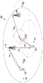
Fig. 1 illustrates an exemplary embodiment of a wireless communication network 100 according to the present disclosure.
As shown in fig. 1, the wireless network 100 includes an enodeb (eNB)101, an eNB102, and an eNB 103. The eNB 101 communicates with the eNB102 and the eNB 103. The eNB 101 also communicates with an Internet Protocol (IP) network 130, such as the internet, a private IP network, or other data network. In this example, eNB102 and eNB 103 are able to access network 130 through eNB 101. each of the enbs 101 to 103 may be referred to as a 'Base Station (BS)', 'Access Point (AP)', 'fifth generation node (5G node)', 'wireless point', 'transmission/reception point (TRP)' or another term having an equivalent technical meaning.
eNB102 provides wireless broadband access to network 130 (through eNB 101) to User Equipment (UEs) within coverage area 120 of eNB 102. Here, the UE includes a UE 111 that may be located in a small enterprise (SB); a UE 112 that may be located in enterprise (E); UE 113, which may be located in a WiFi Hotspot (HS); a UE 114 that may be located in a first residence (R); a UE 115 that may be located in a second residence (R); and a UE 116, which may be a mobile device (M) (such as a cell phone, wireless laptop, or wireless personal digital assistant). Each of the UEs 111 and 116 may represent a mobile device or a fixed device. eNB 103 provides wireless broadband access to network 130 (through eNB 101) to UEs within coverage area 125 of eNB 103. Here, the UE includes UE 115 and UE 116. In some embodiments, one or more of the eNBs 101-103 may communicate with each other and with the UE 111-116 using LTE or LTE-A technology. In addition, one or more of the enbs 101 and 103 may communicate using the inter-eNB coordination method as described herein. Each of the UEs 111-116 may be referred to as a 'terminal', 'Mobile Station (MS)', 'Subscriber Station (SS)', 'Remote Terminal (RT)', 'Wireless Terminal (WT)', 'user equipment' or another term with technical equivalents.
The dashed lines show the general extent of coverage areas 120 and 125, which are shown as being generally circular for purposes of illustration and explanation only. Coverage areas 120 and 125 may have other shapes, including irregular shapes, depending on factors such as the configuration of the eNB and variations in the radio environment associated with natural and man-made obstructions.
In some embodiments, the eNBs 101-103 may communicate with each other and with the UEs 111-116 using Orthogonal Frequency Division Multiplexing (OFDM) or Orthogonal Frequency Division Multiple Access (OFDMA) techniques. In addition, each eNB 101-103 may have a globally unique identifier, such as a unique Base Station Identifier (BSID). The BSID is often a Medium Access Control (MAC) identifier. Each eNB 101-103 may have multiple cells (such as when one sector represents one cell) and each cell may have a physical cell identifier or preamble sequence that is often carried in the synchronization channel.
Although fig. 1 illustrates one example of a wireless network 100, various changes may be made to fig. 1. For example, network 100 may include any number of enbs and any number of UEs in any suitable arrangement. In addition, the eNB 101 may communicate directly with any number of UEs and provide these UEs with wireless broadband access to the network 130. Further, the eNB 101 may provide access to other or additional external networks, such as an external telephone network. In addition, the construction and arrangement of the wireless network 100 is for illustration only.
In some embodiments, the enbs 101-103 and UEs 111-116 may transmit and receive signals over millimeter wave (mmWave) frequency bands (e.g., 28GHz, 30GHz, 38GHz, or 60 GHz). In addition, to improve channel gain, enbs 101 to 103 and UEs 111 to 116 may perform beamforming. Here, the beamforming includes at least one of transmission beamforming and reception beamforming. That is, the enbs 101 to 103 and UEs 111 to 116 may assign directivities to reception signals or transmission signals. To achieve this, the enbs 101 to 103 and UEs 111 to 116 may select at least one serving beam through a beam search procedure.
Fig. 2A and 2B illustrate exemplary embodiments of Orthogonal Frequency Division Multiple Access (OFDMA) transmission and reception paths according to the present disclosure. In fig. 2A, the transmission path 200 may be implemented in an eNB, such as eNB102 of fig. 1. In fig. 2B, receive path 250 may be implemented in a UE, such as UE 116 of fig. 1. However, it will be understood that the receive path 250 may be implemented in an eNB (such as eNB102 of fig. 1) and the transmit path 200 may be implemented in a UE. The transmission path 200 and the reception path 250 may be configured to implement an inter-eNB coordination method as described herein.
In some embodiments, at least some of the components in fig. 2A and 2B may be implemented in software, while other components may be implemented by configurable hardware or a mixture of software and configurable hardware. As a specific example, it should be noted that FFT block 270 and IFFT block 215 may be implemented as configurable software algorithms, where the value of size N may be modified depending on the implementation.
Furthermore, although described as using an FFT and IFFT, this is merely illustrative and should not be construed as limiting the scope of the disclosure. Other types of transforms may be used, such as Discrete Fourier Transform (DFT) and Inverse Discrete Fourier Transform (IDFT) functions. It should be understood that the value of the variable N may be any integer used for DFT and IDFT functions (such as 1, 2, 3, 4, etc.), while the value of the variable N may be any integer used for powers of 2 (such as 1, 2, 4, 8, 16, etc.) of FFT and IFFT functions.
In transmission path 200, a channel coding and modulation block 205 receives a set of information bits, applies coding, such as Turbo or LDPC coding, and modulates the input bits, such as with Quadrature Phase Shift Keying (QPSK) or Quadrature Amplitude Modulation (QAM), to produce a sequence of frequency domain modulation symbols. Serial-to-parallel block 210 converts (such as demultiplexes) the serial modulation symbols into parallel data to produce N parallel symbol streams, where N is the IFFT/FFT size used in BS 102 and UE 116. IFFT block 215 of size N performs IFFT operations on the N parallel symbol streams to produce a time domain output signal. Parallel-to-serial block 220 converts (such as multiplexes) the parallel time-domain output symbols from size N IFFT block 215 to produce a serial time-domain signal. Add cyclic prefix block 225 inserts a cyclic prefix to the time domain signal. Upconverter 230 modulates (such as upconverts) the output of add cyclic prefix block 225 to an RF frequency for transmission over a wireless channel. The signal may also be filtered at baseband before conversion to RF frequency.
The transmitted RF signal reaches the UE 116 after passing through the wireless channel and performs the reverse operation to the operation at the eNB 102. Downconverter 255 downconverts the received signal to baseband frequency and remove cyclic prefix block 260 removes the cyclic prefix to produce a serial time-domain baseband signal. Serial-to-parallel block 265 converts the time-domain baseband signal to parallel time-domain signals. An FFT block 270 of size N performs an FFT algorithm to produce N parallel frequency domain signals. Parallel-to-serial block 275 converts the parallel frequency-domain signals to a sequence of modulated data symbols. Channel decoding and demodulation block 280 demodulates and decodes the modulated symbols to recover the original input data stream.
Each of the eNBs 101-103 may implement a transmission path similar to the transmission to the UE 111-116 in the downlink and may implement a reception path similar to the reception from the UE 111-116 in the uplink. Similarly, each of the UEs 111 and 116 may implement a transmission path corresponding to an architecture for transmission in the uplink to the eNB 101 and 103 and may implement a reception path corresponding to an architecture for reception in the downlink from the eNB 101 and 103.
In some embodiments, an eNB may have one or more cells, and each cell may have one or more antenna arrays. In addition, each array within a cell may have a different frame structure, such as different uplink and downlink ratios in a Time Division Duplex (TDD) system. Multiple TX/RX (transmission/reception) chains may be applied in one array or one cell. One or more antenna arrays in a cell may have the same downlink control channel (such as a synchronization channel, a physical broadcast channel, etc.) transmissions, while other channels (such as data channels) may be transmitted in a frame structure specific to each antenna array.
Although fig. 2A and 2B show examples of OFDMA transmission paths and reception paths, various changes may be made to fig. 2A and 2B. For example, various components in fig. 2A and 2B may be combined, further subdivided, or omitted, and additional components may be added according to particular needs.
Fig. 3A illustrates a block diagram of a terminal in a wireless communication system according to the present disclosure. The structure of the terminal shown in fig. 3A may be understood as an example of the structure of any one of the UEs 111 and 115. The UE 111 and 115 of FIG. 1 may have the same or similar configuration: note, however, that the UE has a wide variety of configurations, and fig. 3A does not limit the disclosure to any particular implementation of the UE.
As shown in fig. 3A, the UE 116 includes an antenna 305, a Radio Frequency (RF) transceiver 310, Transmit (TX) processing circuitry 315, a microphone 320, and Receive (RX) processing circuitry 325. The UE 116 also includes a speaker 330, a processor 340, an input/output (I/O) Interface (IF)345, a keypad 350, a display 355, and a memory 360. The memory 360 includes an Operating System (OS) program 361 and a plurality of applications 362.
The RF transceiver 310 receives from the antenna 305 an incoming RF signal transmitted by an eNB of the network 100. The RF transceiver 310 downconverts the incoming RF signal to generate an Intermediate Frequency (IF) or baseband signal. The IF or baseband signal is sent to RX processing circuitry 325, which RX processing circuitry 325 generates a processed baseband signal by filtering, decoding, and/or digitizing the baseband or IF signal. The RX processing circuitry 325 transmits the processed baseband signal to a speaker 330 (such as voice data) or a processor 340 for further processing (such as web browsing).
TX processing circuitry 315 receives analog or digital voice data from microphone 320 or other outgoing baseband data (such as web data, email, or interactive video game data) from processor 340. TX processing circuitry 315 encodes, multiplexes, and/or digitizes the outgoing baseband data to produce a processed baseband or IF signal. RF transceiver 310 receives the output processed baseband or IF signal from TX processing circuitry 315 and upconverts the baseband or IF signal to an RF signal for transmission over antenna 305.
In some embodiments, processor 340 is a microprocessor or microcontroller. The memory 360 is coupled to the processor 340. A portion of memory 360 may include Random Access Memory (RAM) and another portion of memory 360 may include flash memory or other Read Only Memory (ROM).
The processor 340 may include one or more processors and executes the OS program 361 stored in the memory 360 in order to control the overall operation of the UE 116. In one such operation, processor 340 controls the reception of forward channel signals and the transmission of reverse channel signals by RF transceiver 310, RX processing circuitry 325, and TX processing circuitry 315 in accordance with well-known principles. Processor 340 may also include processing circuitry configured to allocate one or more resources. For example, the processor 340 may include allocator processing circuitry configured to allocate unique carrier indicators; and detector processing circuitry configured to detect a Physical Downlink Control Channel (PDCCH) that schedules a Physical Downlink Shared Channel (PDSCH) in one carrier to receive a Physical Uplink Shared Channel (PUSCH) transmission. Downlink Control Information (DCI) is used for several purposes and is conveyed through a DCI format in each PDCCH. For example, the DCI format may correspond to a downlink assignment for PDSCH reception or an uplink grant for PUSCH transmission.
The processor 340 may also be capable of executing other processes and programs resident in the memory 360, such as the operations of the inter-eNB coordination method for supporting inter-eNB carrier aggregation. It should be understood that inter-eNB carrier aggregation may also be referred to as dual connectivity. Processor 340 may move data into or out of memory 360 as needed to perform processes. In some embodiments, the processor 340 is configured to execute a plurality of applications 362, such as an application for a plurality of user-multiple input multiple output (MU-MI MO) communications, including obtaining a control channel element of a PDCCH. The processor 340 may operate a plurality of applications 362 based on the OS program 361 or in response to a signal received from the eNB. The processor 340 is also coupled to an I/O interface 345, which I/O interface 345 provides the UE 116 with the ability to connect to other devices, such as laptop computers and handheld computers. I/O interface 345 is the communication path between these accessories and controller 340.
Although fig. 3A shows one example of UE 116, various changes may be made to fig. 3. For example, various components in fig. 3A may be combined, further subdivided, or omitted, and additional components may be added according to particular needs. Additionally, although fig. 3A shows the UE 116 operating as a mobile phone, the UE may be configured to operate as other types of mobile or stationary devices.
Fig. 3B illustrates a block diagram of a base station in a wireless communication system according to the present disclosure. The structure of the base station shown in fig. 3B can be understood as an example of the structure of any one of the enbs 101 and 103. The embodiment of eNB102 shown in fig. 3B is for illustration only, and the other enbs 101 of fig. 1 may have the same or similar configurations. However, enbs have a wide variety of configurations, and fig. 3B does not limit the scope of the disclosure to any particular implementation of an eNB. Note that eNB 101 and eNB 103 may include the same or similar structure as eNB 102.
As shown in FIG. 3B, the eNB102 includes multiple antennas 370a-307n, multiple RF transceivers 372a-372n, Transmit (TX) processing circuitry 374, and Receive (RX) processing circuitry 376. In some embodiments, one or more of the plurality of antennas 370a-370n comprises a 2D antenna array. The eNB102 also includes a controller/processor 378, a memory 380, and a backhaul or network interface 382.
The RF transceivers 372a-372n receive incoming RF signals, such as signals transmitted by UEs or other enbs, from the antennas 370a-370 n. RF transceivers 372a-372n downconvert the incoming RF signals to generate IF or baseband signals. The IF or baseband signal is sent to RX processing circuitry 376, which RX processing circuitry 376 generates a processed baseband signal by filtering, decoding, and/or digitizing the baseband or IF signal. The RX processing circuitry 376 transmits the processed baseband signals to the controller/processor 378 for further processing.
TX processing circuitry 374 receives analog or digital data (such as voice data, web data, email, or interactive video game data) from controller/processor 378. TX processing circuitry 374 encodes, multiplexes, and/or digitizes the outgoing baseband data to generate a processed baseband or IF signal. RF transceivers 372a-372n receive the outgoing processed baseband or IF signals from TX processing circuitry 374 and upconvert the baseband or IF signals into RF signals for transmission over antennas 370a-370 n.
The controller/processor 378 may include one or more processors or other processing devices that control overall operation of the eNB 102. For example, the controller/processor 378 may control the reception of forward channel signals and the transmission of reverse channel signals by the RF transceivers 372a-372n, the RX processing circuitry 376, and the TX processing circuitry 315 in accordance with well-known principles. The controller/processor 378 may also support additional functions such as higher-level wireless communication functions. For example, the controller/processor 378 may perform a Blind Interference Sensing (BIS) process, such as that performed by a BIS algorithm, and decode the received signal subtracted by the interfering signal. The controller/processor 378 may support any of a variety of other functions in the eNB 102. In some embodiments, controller/processor 378 includes at least one microprocessor or microcontroller.
Controller/processor 378 is also capable of executing programs and other processes resident in memory 380, such as an OS. The controller/processor 378 can also support channel quality measurement and reporting for systems with 2D antenna arrays, as described in embodiments of the present disclosure. In some embodiments, the controller/processor 378 supports communication between entities, such as a web RTC. Controller/processor 378 may move data into and out of memory 380 as needed to perform processes.
Controller/processor 378 is also coupled to a backhaul or network interface 382. The backhaul or network interface 382 allows the eNB102 to communicate with other devices or systems over a backhaul connection or over a network. Interface 382 may support communication via any suitable wired or wireless connection. For example, when eNB102 is implemented as part of a cellular communication system (such as one supporting 5G, LTE or LTE-a), interface 382 may allow eNB102 to communicate with other enbs over a wired or wireless backhaul connection. When eNB102 is implemented as an access point, interface 382 may allow eNB102 to communicate over a wired or wireless local area network or over a wired or wireless connection to a larger network, such as the internet. Interface 382 includes any suitable structure that supports communication via a wired or wireless connection, such as an ethernet or RF transceiver.
As described in more detail below, the transmit and receive paths of the eNB102 (implemented using the RF transceivers 372a-372n, the TX processing circuitry 374, and/or the RX processing circuitry 376) support aggregated communication with FDD and TDD cells.
Although fig. 3B illustrates one example of an eNB102, various changes may be made to fig. 3B. For example, eNB102 may include any number of each of the components shown in fig. 3B. As a particular example, the access point may include multiple interfaces 382, and the controller/processor 378 may support routing functions to route data between different network addresses. As another particular example, although shown as including a single instance of TX processing circuitry 374 and a single instance of RX processing circuitry 376, eNB102 may include multiple instances of each (such as one for each RF transceiver).
DL signals include data signals conveying information content, control signals conveying DL Control Information (DCI), and Reference Signals (RS), also referred to as pilot signals. The eNodeB transmits data information or DCI through a corresponding Physical DL Shared Channel (PDSCH) or Physical DL Control Channel (PDCCH). Possible DCI formats for downlink assignment include DCI formats 1A, 1B, 1C, 1D, 2A, 2B, 2C, and 2D. The UE may be configured with a transmission mode that determines a downlink unicast reception method of the UE. For a given transmission mode, the UE may receive a unicast downlink assignment using DCI format 1A and one of DCI formats 1B, 1D, 2A, 2B, 2C, or 2D. The eNodeB transmits one or more of multiple types of RS including UE-common RS (crs), channel state information RS (CSI-RS), and demodulation RS (dmrs). CRS is transmitted over the DL system Bandwidth (BW) and may be used by UEs to demodulate data or control signals or perform measurements. To reduce CRS overhead, the eNodeB may transmit a lesser density of CSI-RSs than CRS in the time and/or frequency domains. For channel measurement, non-zero power CSI-RS (NZP CSI-RS) resources may be used. For Interference Measurement Resources (IMR), CSI interference measurement (CSI-IM) resources associated with zero power CSI-RS (ZP CSI-RS) may be used. The UE may determine the CSI-RS transmission parameters through higher layer signaling from the eNodeB. DMRSs are transmitted only in BW of the corresponding PDSCH, and the UE may demodulate information in the PDSCH using the DMRSs.
Fig. 4 is a diagram illustrating a structure of a DL Transmission Time Interval (TTI) according to the present disclosure.
Referring to fig. 4, DL signaling uses Orthogonal Frequency Division Multiplexing (OFDM) and DL TTI has a duration of 1 millisecond (ms) and includes N14 OFDM symbols in the time domain (or two slots) and K Resource Blocks (RBs) in the frequency domain. Control Channels (CCH) of a first type at a first N1Transmission (including no transmission, N) in one OFDM symbol 41010). Remaining N-N1One OFDM symbol is mainly used for transmitting PDSCH 420 and for transmitting a second type of cch (ecch)430 in some RBs of the TTI. Each RB is composed of Sub-carrier or Resource Element (RE) composition, and UE is allocated MPDSCHTotal RB used for PDSCH BW Transmission
 A unit of 1RB in frequency and 1 slot in time is referred to as a physical RB (prb).
The E-UTRAN supports relaying by having a Relay Node (RN) or relay Base Station (BS) wirelessly connected to an eNB serving the RN, referred to as a donor eNB (denb) or donor BS.
Fig. 5 is a diagram illustrating an example cellular network 500 with relay base stations equipped with wireless backhaul in accordance with the present disclosure.
Referring to fig. 5, RN 530 is wirelessly connected to an eNB serving the RN, referred to as donor eNB (denb) or donor BS 510, over a Un interface 513, which Un interface 513 is also referred to as the RN's backhaul. The RN supports eNB functionality, i.e. it terminates the radio protocol of the E-UTRA radio interface, as well as the S1 and X2 interfaces. In addition to eNB functionality, the RN also supports a subset of UE functionality, e.g., physical layer, layer 2, RRC, and NAS functionality, for wireless connectivity to the DeNB. The UE may be served directly by the DeNB (such as UE 520), or it may be served by the RN (such as UE 540). For in-band relay operation, the wireless backhaul link 513 for the RN and the wireless access links (511, 531) for the DeNB and the RN share the same frequency band.
For in-band relay operation, time-frequency resources are set aside for eNB-RN transmissions by time multiplexing the eNB-RN and RN-UE transmissions. The subframe in which eNB-RN transmission may occur is configured by higher layers. The downlink subframes configured for eNB-to-RN transmissions should be configured by the relay node as MBSFN subframes for its UEs. eNB-to-RN transmissions occur in downlink subframes and RN-to-eNB transmissions occur in uplink subframes.
Fig. 6 is a diagram illustrating an example time division multiplexing of eNB-RN and RN-UE transmissions 600 according to the present disclosure.
Referring to fig. 6, eNB-RN transmissions may occur in time slot t 1514, while RN-UE and eNB-UE transmissions occur in time slot t 2512. This may avoid interference between the eNB-RN link and the RN/eNB-UE link. In addition, further orthogonalization of resources is typically done between multiple RNs attached to the same eNB. In this example, the time-frequency resources corresponding to time slot t1 are further divided across multiple eNB-RN links (e.g., in the frequency or time domain) in order to avoid interference between backhaul links. If the inter-cell interference is small enough, resource reuse can be performed for cells of different RNs. However, due to orthogonal resource allocation between the backhaul link and the access link, such wireless relay systems do not easily scale with the number of RNs and UEs in the network, which limits their application in dense cell deployment scenarios.
The E-UTRAN also supports Dual Connectivity (DC) operation, whereby multiple Rx/Tx UEs in RRC _ CONNECTED are configured to utilize radio resources provided by two different schedulers located in two enbs CONNECTED by a non-ideal backhaul over the X2 interface. The enbs involved in the DC of a certain UE may assume two different roles: the eNB may act as a MeNB or as a SeNB. In DC, a UE is connected to one MeNB and one SeNB. A set of serving cells configured for a UE consists of two subsets: a Master Cell Group (MCG) of one or more serving cells containing the MeNB and a Secondary Cell Group (SCG) of one or more serving cells containing the SeNB.
Unified wireless backhaul and access network
In one embodiment, a Base Station (BS) may provide wireless access services to one or more UEs on one or more frequency bands. In addition, the BS may also provide wireless backhaul services to one or more relay BSs on all or a subset of the frequency bands used for the BS's wireless access services with no minimal or no performance impact on its serving UEs. Such a BS is called an anchor BS. The relay BS may also have a wired backhaul connection to the anchor BS. The relay BS provides wireless access services to a plurality of UEs on one or more frequency bands that serve as a backhaul between the anchor BS and the relay BS. In other words, the time-frequency resources of the frequency band are shared between the wireless access of the anchor BS, the wireless access of the relay BS, and the wireless backhaul of the relay BS. The relay BS supports the eNB function. From the UE perspective, the relay BS is considered to be an eNB. The disclosed invention may enable a new relay BS to be deployed and attached to an anchor BS or an idle relay BS to be activated without requiring installation of a wired backhaul connection between the anchor BS and the relay BS and with minimal or no negative performance impact on other relay BSs that are wirelessly attached or wired to the same anchor BS and UEs served by the anchor BS and other relay BSs. Such wireless systems are referred to as unified wireless backhaul and access networks.
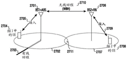
Fig. 7 illustrates an example of a unified wireless backhaul and access network 700 according to the present disclosure.
Referring to fig. 7, anchor B3S 710 is configured with two frequency bands (f1 and f2), where the coverage area 750 of f1 is larger than the coverage area 760 of f2 because the frequency of f1 (600MHz-2GHz) is lower than the frequency of f2 (e.g., 3GHz-300 GHz). The relay BS 730 is configured with one frequency band (f2) of the coverage area 770. A UE 720 located within the coverage of the anchor BS at f1, but not within the coverage of the anchor BS or the relay BS at f2, is served by the anchor BS over the access link 721. A UE 740 in coverage of the relay BS 730 at f2 may associate with the relay BS 730 at f2 over an access link 742. When the UE is also within coverage of the anchor BS at f1, the UE may also be associated with the anchor BS at f1 over access link 741 using dual connectivity or carrier aggregation configuration at the same time. In this case, control plane signaling (RRC and mobility handling) and/or high QoS data may be delivered to the UE through f1, and best effort traffic may be delivered to the UE through f 2. In case of dual connectivity, from the UE perspective, the anchor BS is MeNB and the relay BS is SeNB. In one alternative, both DL and UL support relay BS-UE communication. In another alternative, only DL is supported for relay BS-UE communication and UL is supported by UE-to-anchor BS communication.
Note that a stand-alone system based on frequency f2 is also possible. In this case, the frequency f1 in fig. 7 and the corresponding connection 721 between the UE to the anchor BS on f1 do not exist.
In one embodiment, a relay BS may be simultaneously attached to or associated with more than one anchor BS. This configuration may provide the following advantages. The multi-backhaul links to multiple anchor BSs increase the aggregate backhaul capacity, which enables more UEs to be served by the relay BS. Multiple backhaul links to different anchor BSs also avoid a single point of failure in the network, so that blocking of backhaul links does not result in service interruption for the entire cell provided by the relay BS. In one example, all or a subset of the backhaul links to different anchor BSs are active simultaneously. The set of active backhaul links may depend on factors such as the load of the relay BS cell, the load of the anchor BS, or the channel quality/status (e.g., outage) of the backhaul links. In another example, only one backhaul link is active at a time. Similarly, the active backhaul link may be selected depending on factors such as the load of the relay BS cell, the load of the anchor BS, or the channel quality/status (e.g., outage) of the backhaul link. In addition, when the relay BS is simultaneously attached to more than one anchor BS, the relay BS may be used to serve UEs connected to any one of the anchor BSs (within the coverage of the relay BS).
Fig. 8 illustrates an example of multiple backhaul links to multiple anchor BSs according to this disclosure. Referring to fig. 8, relay BS 830 is associated or attached with both anchor BS 710 (through backhaul link 731) and anchor BS 880 (through backhaul link 832). The relay BS is also used to serve (812) UE 810 (which is within the coverage of the relay BS) which is connected 811 to the anchor BS 880 on f1 with a corresponding coverage 850.
In one embodiment, the UE may be associated with more than one relay BS at the same time. This has the following advantages: blocking one relay BS does not cause service interruption for the UE because the UE can continue to be served from another relay BS. In one example, all or a subset of the access links to different relay BSs are active simultaneously. The set of active access links may depend on factors such as the load of the relay BS cell or the channel quality/status (e.g., outage) of the access links. In another example, only one access link is active at a time. Similarly, the active access link may be selected depending on factors such as the load of the relay BS cell or the channel quality/status (e.g., outage) of the access link.
In one embodiment, the UE may be associated with the first anchor BS at f1 and the relay BS at f2, but the anchor BS associated with or attached to the relay BS is a second anchor BS (i.e., not identical to the first anchor BS). This configuration is beneficial when the relay BS is not actually within the coverage of the first anchor BS at f2, or the backhaul link to the first anchor BS is not appropriate due to poor SINR conditions.
Fig. 9 illustrates an example of different anchor BS associations of a relay BS and a terminal according to the present disclosure.
Referring to fig. 9, the relay BS 930 is associated or attached (via backhaul link 932) with the anchor BS 980, while its serving UE 740 is associated with the anchor BS 710 at f 1.
In one embodiment, a relay BS may be associated or attached with another relay BS, which in turn may be associated with an anchor BS or with another relay BS.
In one embodiment, there may be a dedicated RF front end and antenna panel for the backhaul link and another dedicated RF front end and antenna panel for the access link at the relay BS. A similar arrangement may be made at the anchor BS. In addition, there may be another dedicated RF front end and antenna panel for the access link at the lower frequency f 1. In another embodiment, there may be a common RF front end and antenna panel at the relay BS that is shared between the backhaul link and the access link. A similar arrangement may be made at the anchor BS. In addition, there may be another dedicated RF front end and antenna panel for the access link at the lower frequency f 1.
In one embodiment, the backhaul and access sharing the same frequency band are based on the same radio access technology and modulation waveform (such as OFDM), but different OFDM symbol numerologies of the radio access technology used for backhaul and access, such as subcarrier spacing and/or OFDM symbol duration and/or cyclic prefix overhead, may be configured. This may be due to different radio channel properties of the backhaul link and the access link, different hardware and signal processing capabilities of transmitters and receivers of the backhaul link and the access link, different traffic patterns or loads of the backhaul link and the access link, different data rates, delay requirements and QoS requirements of the backhaul link and the access link, etc. An example of the differences between the backhaul link and the access link is given in table 1.
TABLE 1

In one example, to meet the low latency requirement of the backhaul link, the OFDM symbol duration of the backhaul link is shortened compared to the duration of the access link, but the subcarrier spacing of the backhaul link is increased compared to the subcarrier spacing of the access link. In another example, for a certain deployment scenario, when the channel delay spread of the backhaul link is large due to a large coverage area, the OFDM symbol duration of the backhaul link is large compared to the access link (in order to maintain the same or similar cyclic prefix overhead) and the subcarrier spacing is shortened to reduce the loss in data rate. In another example, for a certain deployment scenario, when the channel delay spread of the backhaul link is short due to dominant LOS channel conditions, the cyclic prefix overhead of the backhaul link may be smaller than the cyclic prefix overhead of the access link. In another example, when different numerologies are configured for the backhaul link and the access link, the subcarrier spacing or OFDM symbol duration of one numerologie is an integer multiple of the other. Such a configuration may be advantageous for certain spectrum sharing schemes between backhaul and access, such as time division multiplexing and space division multiplexing, to maximize resource utilization (as alignment of symbol or subframe or frame boundaries may be easier).
In one embodiment, backhaul and access sharing the same frequency band are based on the same radio access technology and modulation waveform (such as OFDM), but different slot/subframe/frame structure digital schemes (such as slot/subframe/frame duration or composition) are configured for the backhaul link and the access link. For example, a subframe for a backhaul link consists of X OFDM symbols, and a subframe for an access link consists of Y OFDM symbols, where X and Y may be different. Multiplexing data of different traffic types in a single transmission over the backhaul link is more efficient, whereas a single transmission over the access link may contain only one or a small subset of the data types that need to be delivered to the UE according to the corresponding QoS requirements. Thus, regardless of the traffic type, there may be a single delay requirement for the backhaul link, while the delay requirement for the access link differs depending on the type of data to be delivered. Shorter subframe durations may be configured for more stringent delay requirements.
In one embodiment, the backhaul and access sharing the same frequency band are based on the same radio access technology and modulation waveform (such as OFDM), but different system configurations of the radio access technology used for backhaul and access may be configured, such as system bandwidth, transmission power, transmission mode, DL/UL resource allocation scheme, modulation scheme. In one example, the backhaul link may be configured with a larger system bandwidth or a higher modulation order than that configured for the access link to achieve a higher data rate for the backhaul link. In another example, due to traffic aggregation over the backhaul link (which means that backhaul traffic is less dynamic or bursty), it is advantageous to configure the backhaul link with a DL/UL resource allocation/assignment scheme with reduced dynamic control signaling overhead. Examples of DL/UL resource allocation/assignment schemes include: a plurality of subframe schedules, whereby a single dynamic control channel schedules data transmission in a plurality of consecutive subframes; and semi-persistent scheduling whereby resources for data transmission are assigned in a semi-persistent manner, such as reserving subframe blocks for data transmission in a periodic manner. For the access link, dynamic scheduling or scheduling with reduced control overhead may be used for the UE, depending on the traffic type. In another example, due to the static nature of relay BSs, a closed loop transmission mode may be configured for the backhaul link. For the access link, both open-loop and closed-loop transmission modes may be configured for the UE, depending on the channel conditions and UE mobility.
In one embodiment, the waveforms for backhaul and access sharing the same frequency band are different. In one example, schemes that do not require CP overhead such as FBMC (filter bank multicarrier) are used for the backhaul link, while OFDM is used for the access link, where multipath channel conditions require robust inter-symbol interference (ISI) protection with large cyclic prefix duration. Another advantage of using such a backhaul scheme is that the receiver may be more complex than the UE and more complex or signal processing intensive interference cancellation techniques may be applied to mitigate ISI due to no CP addition at the transmitter.
Backhaul and access spectrum sharing scheme
In the following embodiments, a TDD frame structure as shown in fig. 10 is assumed. Referring to fig. 10, a frame 1000 includes one or more consecutive DL subframes 1010 followed by special subframes 1015 and one or more consecutive UL subframes 1020. The special subframe 1015 consists of a DL part 1011, a guard period 1012, and an UL part 1013. The assumed frame structure is for illustration only and should not be construed as limiting the scope of the present disclosure.
In the present disclosure, it is assumed that the backhaul link and the access link both have the same frame structure as shown in fig. 10. It is not excluded that the backhaul link and the access link may have different frame structures.
The backhaul link and the access link share the same frequency band. When a transmission on the access link interferes with backhaul link reception, the relay BS is unable to simultaneously receive (from the anchor BS) on the backhaul link and transmit (to the UE) on the access link. Similarly, when a transmission on the backhaul link interferes with the access link reception, the relay BS is not able to simultaneously transmit on the backhaul link (to the anchor BS) and receive on the access link (from the UE). This is known as the "half duplex" problem for relay BSs. Inter-link interference may be the result of insufficient isolation between the antennas of the backhaul link and the antennas of the access link. Therefore, a spectrum sharing scheme needs to be designed between the backhaul link and the access link.
In a first approach, backhaul frames and access frames are multiplexed in the time domain to avoid inter-link interference.
Fig. 11 illustrates an example of time division multiplexing between access frames 1110 and backhaul frames 1120 in accordance with the present disclosure.
In a second approach, fig. 12 illustrates an exemplary frequency division multiplexing of backhaul and access frames according to the present disclosure.
As shown in fig. 12, the backhaul frame and the access frame are multiplexed in the frequency domain. The backhaul frame is allocated in a first frequency sub-band 1210 and the access frame is allocated in a second frequency sub-band 1230. Guard band 1220 is needed to avoid inter-link interference. However, the guard band may be reduced by applying frequency domain filtering to each frequency sub-band. The second method has the following advantages over the first method: flexible scheduling or resource allocation in time is allowed for the backhaul link and the access link.
In a third approach, backhaul frames and access frames are multiplexed in the spatial domain. To overcome the "half-duplex" problem, the DL and UL of the backhaul link are spatially multiplexed with the UL and DL of the access link, respectively, on the same time-frequency resources. For a relay BS, the DL-to-UL switching point of the backhaul link and the UL-to-DL switching point of the access link are aligned; similarly, the UL-to-DL switching point of the backhaul link and the DL-to-UL switching point of the access link are aligned. It is assumed that the anchor BS, the relay BS and the UE are capable of high order transmission and/or reception beamforming, which is feasible when they are equipped with a large number of antennas. In addition, at high frequencies (such as 20GHz-300GHz), a reasonably small antenna panel form factor is feasible.
Fig. 13 illustrates an example of spatial multiplexing between backhaul and access links according to the present disclosure. In contrast to the first and second approaches, a maximum sharing of spectrum resources may be achieved between the backhaul link and the access link.
Referring to fig. 13, DL of backhaul link 1310 is spatially multiplexed with UL of access link 1320 on the same time-frequency resource such that the relay BS performs reception on the backhaul link and the access link only at a given time 1350. Similarly, the UL of backhaul link 1330 is spatially multiplexed with the DL of access link 1340 on the same time-frequency resources such that the relay BS performs transmission on the backhaul link and the access link only at a given time 1360.
In one embodiment, a combination of the above methods may be employed. For example, in order to achieve a greater data rate of the backhaul link, the backhaul link may be exclusively allocated with frequency subbands, and the remaining bandwidth may be shared between the backhaul link and the access link through time division multiplexing according to the first method or through space division multiplexing according to the third method.
In order to achieve spectrum sharing between the backhaul link and the access link, a coordination protocol or procedure is required between the anchor BS and the relay BS.
Fig. 14 illustrates an example resource coordination process between an anchor BS and a relay BS according to this disclosure.
Referring to fig. 14, in 1401, an anchor BS determines a backhaul resource or frame structure configuration and signals a relay BS (such as through a common control or broadcast channel). Another example of control signaling may be the time location of the backhaul DL-to-UL and UL-to-DL switching points.
In 1403, upon receiving the backhaul resource configuration, each relay BS may determine where/how to receive and transmit to the anchor BS and the time-frequency resources available for scheduling transmission and reception of its own UE.
Fig. 15 illustrates an example of a resource coordination procedure between an anchor BS and a relay BS according to a third method of a spectrum sharing scheme according to the present disclosure.
Referring to fig. 15, in 1501, an anchor BS determines backhaul DL time-frequency resources and backhaul UL time-frequency resources and signals a relay BS (such as through a common control or broadcast channel).
In 1503, upon receiving the backhaul DL time-frequency resource configuration, each relay BS may determine time-frequency resources to receive backhaul DL transmissions from the anchor BS and schedule and receive access UL transmissions from its own UE.
In 1505, upon receiving the backhaul UL time-frequency resource configuration, each relay BS may determine time-frequency resources to transmit backhaul UL information to the anchor BS and schedule and transmit access DL information to its own UE.
When there are time-frequency resources that are not indicated as being allocated for the backhaul, the relay BS may perform scheduling of access in a flexible manner (without being constrained by the backhaul resource configuration). In an alternative, the relay BS is not allowed to schedule/perform access transmission/reception for these resources. In another alternative, whether the relay BS is free to schedule/perform access transmission/reception for those resources is indicated by the anchor BS.
In another example, instead of signaling the backhaul resource configuration, the anchor BS signals the available access resource configuration to the relay BS. The relay BS then derives a backhaul resource configuration from the available access resource configurations according to a spectrum sharing scheme.
In one embodiment, the relay BS may indicate to the anchor BS the desired or required access resources to serve its UEs, so that the anchor BS may take this information into account when deciding on the backhaul resource configuration according to the employed spectrum sharing scheme.
Fig. 16 illustrates an exemplary spatial multiplexing of backhaul and access frames according to the present disclosure.
In one embodiment, to achieve efficient support of multiple relay BSs by an anchor BS, transmissions from the anchor BS to the multiple relay BSs may be performed simultaneously through spatial multiplexing. Spatial multiplexing interference can be mitigated by multi-user precoding algorithms that optimize certain performance metrics, such as signal-to-leakage-and-noise ratio (SLNR) maximization or zero forcing of multi-user interference. Spatial multiplexing of multiple relay BSs by an anchor BS is shown in fig. 16, where the anchor BS 1610 performs precoding and simultaneously transmits 1621 and 1631 to the relay BSs 1620 and 1630.
Fig. 17A and 17B illustrate two exemplary spatial multiplexes 1700a, 1700B of relay BS group based backhaul and access frames according to the present disclosure.
The relay BSs associated with the anchor BS are grouped such that backhaul transmission and/or reception to the relay BSs within the group is performed by space division multiplexing, while backhaul transmission and/or reception is orthogonalized between the groups by time division multiplexing/frequency division multiplexing. Such grouping is beneficial to minimize multi-user interference between relay BSs to an acceptable level when the number of associated relay BSs is greater than the number of antennas at the anchor BS. As shown in fig. 17A, relay BS a 1720 and relay BS B1730 belong to a first SDM group active at time 1; and as shown in fig. 17B, relay BS C1740 and relay BS D1750 belong to the second SDM group that is active at time 2. The relay BS group is active when the corresponding backhaul transmission/reception is ongoing. During the duration of relay BS group inactivity, the relay BSs belonging to the relay BS group may schedule/perform access transmission/reception for their own UEs in a flexible manner (without limitation by backhaul resource configuration). Under certain deployment conditions, full scheduling flexibility of relay BSs belonging to an inactive relay BS group may not always be possible if significant inter-relay BS interference may occur. In this case, further coordination between relay BSs to mitigate inter-relay BS interference may be advantageous. In the present disclosure, it should be assumed that relay BSs belonging to the inactive relay BS group have full scheduling flexibility, but should not be construed as limiting the scope of the present disclosure.
Fig. 18 illustrates exemplary backhaul and access DL/UL resource allocation according to a third method of a spectrum sharing scheme when there are multiple relay BS SDM groups according to the present disclosure. In this embodiment, relay BS SDM grouping (group I (G-I) and group II (G-II)) is performed for backhaul DL instead of backhaul UL. When the anchor BS is performing backhaul DL transmission to the group I1810, the relay BS belonging to the group I performs backhaul DL reception and access UL reception 1830. Meanwhile, the relay BS belonging to group II can perform flexible access scheduling/transmission/reception for its own UE 1850. Similarly, when the anchor BS is performing backhaul DL transmission to group II 1820, the relay BS belonging to group II performs backhaul DL reception and access UL reception 1860. Meanwhile, the relay BS belonging to the group I may perform flexible access scheduling/transmission/reception for its own UE 1840. When the anchor BS is performing backhaul UL reception, the relay BSs of group I and group II both perform backhaul UL transmission and access DL transmission 1880 and 1890.
Fig. 19 illustrates another exemplary backhaul and access DL/UL resource allocation according to a third method of a spectrum sharing scheme when there are multiple relay BS SDM groups according to the present disclosure. In this embodiment, relay BS SDM grouping (group I and group II) is performed for both backhaul DL and backhaul UL. Because it is similar to the description of fig. 18, a description of the backhaul DL duration is omitted. When the anchor BS is performing backhaul UL reception of group I1910, the relay BS belonging to group I performs backhaul UL transmission and access DL transmission 1950. Meanwhile, a relay BS belonging to group II may perform flexible access scheduling/transmission/reception for its own UE 1970. Similarly, when the anchor BS is performing backhaul UL reception of group II 1930, the relay BS belonging to group II performs backhaul UL transmission and access DL transmission 1981. Meanwhile, a relay BS belonging to group I may perform flexible access scheduling/transmission/reception for its own UE 1960.
In one embodiment, the SDM group specific backhaul resource configuration is signaled to the relay BS. In one example, the relay BS receives only backhaul resource configurations related to the group to which it belongs. From the relay BS perspective, time-frequency resources that are not part of the configured group-specific backhaul resources may be used for flexible access scheduling. An anchor BS-relay BS coordination procedure similar to that shown in fig. 15 may be applied. In another example, each relay BS is signaled with a group identity. In addition, the backhaul resource configuration of all relay BS SDM groups is signaled to the relay BSs. The relay BS identifies its own backhaul resources according to the indicated group identity. Backhaul time-frequency resources configured for other group identities may be used for flexible access scheduling.
In one embodiment, assuming the SDM scheme of the relay BS groups as shown in fig. 17 and the exemplary resource allocation scheme as shown in fig. 18 or fig. 19, the UE may benefit from additional scheduling flexibility and spectrum utilization improvements when the UE is associated with at least one relay BS in at least two relay BS SDM groups at the same time, which is not possible when the UE is associated with only one relay BS. For example, when one relay BS (of one SDM group) associated with the UE is performing backhaul DL reception and UL access reception, the UE may transmit to the relay BS in the UL, or it may receive from a second relay BS (of another SDM group) associated with the UE on the DL. The UE may also transmit to the second relay BS in the UL. In this case, the ability of the second relay BS to schedule in the DL or UL may enhance the spectrum utilization of the UE.
Fig. 20 illustrates an exemplary scenario in which a UE may increase DL reception opportunities through association with multiple relay BSs according to the present disclosure.
Referring to fig. 20, UE a 2040 is associated with relay BS I2020, UE B2060 is associated with relay BS II 2030, and UE C2050 is associated with relay BS I2020 and relay BS II 2030. At time 12000 a, anchor BS 2010 is transmitting to relay BS II 2030, and UE B is transmitting to relay BS II in UL. Meanwhile, the relay BS I may perform access stratum scheduling in a flexible manner; in this example, relay BS1 is transmitting in DL to both UE a and UE C. At time 22000 b, the anchor BS 2010 switches to transmitting in DL to the relay BS I2020 and UE a transmits in UL. Meanwhile, relay BS II transmits data to UE B and UE C in DL. In this example, unlike UE a and UE B, which may receive data in the DL only at a given time, UE C is given the flexibility to receive data in the DL at two times.
Fig. 21 illustrates another example of improved spectrum utilization and scheduling flexibility for terminals associated with relay BSs from multiple relay SDM groups in accordance with the present disclosure.
Referring to fig. 21, the SDM scheme is similar to the scheme shown in fig. 18. UE B is associated with relay BS II and UE C is associated with relay BS I and relay BS II. Initially, UE C is receiving and transmitting to relay BS II (such as 2120, 2121, 2122). However, unlike UE B, which cannot switch to receiving DL data throughout the DL backhaul reception period of relay BS II and must suspend DL and UL activities after all UL data has been transmitted, UE C may switch to receiving DL data from relay BS I (2132 and 2142, respectively) and transmitting UL data thereto. UE C may then switch back to communicating with relay BS II (2150).
Fig. 22 shows an example cellular system consisting of a base station BS1 according to the present disclosure. BS12701 provides radio access to UEs located in a particular geographic coverage area 2702. The group of UEs served by BS12701 is referred to as UE group 1; an exemplary UE that is a member of UE group 1, i.e., served by BS12701, is identified in fig. 22 as UE 2704. BS12701 transmits information to and receives information from UE group 1 over radio access link 2705. The BS-to-UE transmission direction is referred to as the Downlink (DL) of the radio access link 2705. The UE-to-BS transmission direction is referred to as the Uplink (UL) of the radio access link 2705. DL information intended for a particular UE in UE group 1 arrives at BS12701 from an information source over a wired backhaul 2703. As an example, the wired backhaul may include an optical fiber connecting the BS1 to the infrastructure of an Internet Service Provider (ISP) and thereafter to the internet, where the website accessed by the UE is the source of the information. UL information transmitted by a particular UE to BS12701 is conveyed over wired backhaul 2703 to the destination of the information. As in the previous example, a website on the internet accessed by the UE may be the destination of the information.
The cellular system shown in fig. 22 also comprises a base station BS 22706, which provides radio access to UEs located in a specific geographical coverage area 2707. As indicated by 2711, coverage areas 2702 and 2707 of BS 2701 and BS2706 may overlap. The group of UEs served by BS2706 is referred to as UE group 2; an exemplary UE that is a member of UE group 2, i.e., served by BS2706, is identified in fig. 22 as UE 2708. BS 22706 transmits information to UE group 2 and receives information from UE group 2 over radio access link 2709. The definition of DL and UL transmission directions with respect to the radio access link 2709 is the same as that with respect to the radio access link 2705.
Unlike BS12701, BS 22706 does not have a wired backhaul. In contrast, BS12701 provides service to BS 22706 over wireless backhaul link (WBH)2710, similar to the service provided to BS12701 by wired backhaul link 2703. DL information intended for a particular UE in UE group 2 arrives at BS12701 through wired backhaul 2703 from an information source and is then transmitted by BS12701 to BS 22706 over WBH link 2710. Similarly, UL information transmitted by a particular UE in UE group 2 to BS 22706 is transmitted by BS 22706 over WBH link 2710 to BS 2701 and then by BS12701 over wired backhaul 2703 to the destination of the information. The source and destination of information to and from the UEs in UE group 2, respectively, is similar to that described previously with respect to the source and destination of information to and from the UEs in UE group 1, respectively.
BS 22706 is a Relay Node (RN) with respect to BS12701, as shown at 2706 of fig. 22, since BS12701 relays information to and from UE group 2 served by BS 22706 over WBH 2710. The term "RN" as will be used hereinafter in the remainder of this disclosure will be understood in context. BS12701 may consider "anchor" BS2/RN 2706 by providing backhaul services thereto. The term "ABS", meaning "anchor BS", will be used in the remainder of this disclosure; it should be understood that it represents BS12701 in the context of fig. 22.
It may be noted that the cellular system, an example of which is depicted in fig. 22, may be composed of several ABSs and several RNs, each with a coverage area serving a certain group of UEs, where each RN is anchored by a subset of the ABSs. The communication between each ABS and RN and the group of UEs served by it is as described in the context of fig. 22, respectively. Similarly, the communication between each ABS and the RN anchored by it is as described in the context of fig. 22. Such a cellular system will be referred to as a unified wireless backhaul and access system in this disclosure.
Fig. 23 illustrates a subframe according to the present disclosure. In the following text, "SF" and "subframe" will be used interchangeably. In this figure, the horizontal dimension represents time, while the vertical dimension represents frequency. Fig. 23 shows SF 2801 consisting of a time-frequency grid comprising a number N of OFDM symbols in time, numbered from 1 to N, and a number S of subcarriers in frequency, numbered from 1 to S. In another explanation, SF 2801 consists of N OFDM symbols arranged sequentially in time, where each OFDM symbol consists of S Subcarriers (SC) in frequency.
In the context of fig. 22, with respect to ABS 2701, transmissions to and from UEs in UE group 1 are in units of time of SF. Some set of OFDM symbols in the SF may be used for DL transmissions from the ABS 2701 to the UEs in UE group 1, while some other set of OFDM symbols in the SF may be used for UL transmissions from the UEs in UE group 1 to the ABS 2701. Similar descriptions apply to RN 2706 in the context of fig. 7 with respect to transmissions to and from UEs in UE group 2.
Fig. 24 shows a subframe SF 2901 with DL and UL transmission regions according to the present disclosure. The following description relates to communication between a BS and a group of UEs; in the context of fig. 22, a BS may refer to an ABS 2701 or an RN 2706, while the group of UEs may refer to UEs in UE group 1 or UE group 2. SF 2901 consists of a time-frequency grid comprising a certain number (D + G + U) OFDM symbols in time and a certain number S subcarriers in frequency. In another interpretation, SF 2901 is composed of a plurality of (D + G + U) OFDM symbols arranged sequentially in time, where each OFDM symbol is composed of S subcarriers in frequency. SF 2901 consists of the following.
To the UE.
S in numberDCA subcarrier. The DL control region is used to transmit control information from the BS to the UE. Below is provided
The contents of the DL control area are further detailed in the description of (a).
The portion of the DL area 2902 outside the DL control area is referred to as the DL data area. DL number
The data region is used to transmit user information from the BS to the UE. Further details are set forth in the description below
Contents of the DL data area.
4. Gap region 2904 is composed of G sequential symbols in which no transmission occurs. BS and UE
Such gaps may be utilized to transition from transmitting and receiving information to receiving and transmitting information, respectively.
S in numberUCA subcarrier. The UL control region is used for transmission of control information from the UE to the BS. Below is provided
The contents of the UL control region are further specified in the description of (a).
The portion of UL region 2905 outside of the UL control region is referred to as the UL data region. The UL data region is used to transmit user information from the UE to the BS. The contents of the UL data region are explained in further detail in the following description.
Each symbol in the DL and UL regions may have a different number of occupied sub-carriers. In other words, each symbol in the DL region may have a different number of subcarriers on which the BS transmits to the UE, and likewise, each symbol in the UL region may have a different number of subcarriers on which any one of the UEs transmits to the BS.
9. In some embodiments, the temporal order of the regions in SF 2901 may be UL regions, followed by gaps, and followed by DL regions.
10. In some embodiments, the DL region may be composed of groups of non-contiguous symbols, where each such group may or may not contain another subset of symbols, containing a DL control region within the symbol group. Similarly, the UL region may be composed of multiple sets of non-contiguous symbols, where each such set may or may not contain another subset of symbols, containing the UL control region within the symbol set. There may also be multiple gaps in the SF.
11. In some embodiments, SF 2901 may consist of only DL regions, i.e., such that G ═ U ═ 0;
further, the DL region may or may not contain a DL control region. In some of the further embodiments, the first and second,
the SF 2901 may consist of only UL regions, i.e., such that D ═ G ═ 0; in addition, the UL region may be wrapped
With or without the UL control region.
12. In some embodiments, DL control area 2903 may occupy all SCs in DL area 2902. Similarly, in some embodiments, UL control region 2906 may occupy all SCs in UL region 2905.
The contents of the respective regions in SF 2901 are described below in a to F.
A.dl control region 2903 may contain several DL control channels. The DL control channel transmitted from the BS to the UE informs the UE of details about the DL data region, UL data and/or control region and/or additional DL control regions, such as a location in the SF and a Modulation and Coding Scheme (MCS) used to transmit the region. The time-frequency region corresponding to each DL control channel may include subcarrier locations with pilot or reference samples to help the UE obtain system timing and correct hardware impairments, such as mismatch between the oscillator frequencies of the UE and BS, and to perform channel estimation to help demodulation and decoding of the control channels.
B. The DL control channel in a particular SF may include Ack-Nack feedback for UL data transmission in a previous or current SF.
C. The term PDCCH (physical downlink control channel) will be used to refer to a specific DL control channel. Dl control region 2903 may be composed at least in part of a first set of PDCCHs, wherein each PDCCH of the set contains information that has a correlation with, i.e., may be recovered (may be demodulated, decoded and interpreted) by, a particular UE of the first set of UEs. Further, DL control region 2903 may be composed, at least in part, of a second set of PDCCHs, each of which has a correlation with each UE of a second set of UEs, which may or may not overlap with the first set. The first and second sets of PDCCHs are referred to as unicast and multicast PDCCHs, respectively. The location of the PDCCH in the time-frequency grid may be conveyed to the UE served by the PDCCH by semi-static RRC signaling. Alternatively, the PDCCH may recur at known frequency locations according to a schedule defined in the system specification. Alternatively, the location of the PDCCH may be indicated by a different control channel present in DL control region 2903. Similarly and additionally, the MCS used to encode and modulate the PDCCH is one of a set of MCSs defined in the system specification and known to the UE. The mapping of the UE to the time-frequency grid of the control region 903 of the modulation samples of the control information part related to the UE is also known. The ue can search for a PDCCH for it on the DL control region by using various hypotheses on the PDCCH information size in bits, the MCS used to encode the PDCCH information, and the position of the PDCCH within the DL control region. This process is called blind decoding.
D. On the uplink, Ack/Nack (a/N) or CSI feedback may be configured to be transmitted in UL control region 2906. The a/N refers to ack-nack feedback from the UE regarding the success or failure of reception of downlink data packets. As with the DL control region, the UL control region may include subcarrier locations with pilot or reference samples to help the BS correct for mismatches between the oscillator frequencies of the UE and the BS, and to perform channel estimation to help demodulation and decoding of the UL control channel.
The e.dl data region contains user information transmission from the BS to the UE. The term PDSCH (physical downlink shared channel) will be used in this disclosure to refer to a data channel transmitted by the BS to UEs in the DL data region. The time-frequency grid used to transmit PDSCH to a particular UE may contain subcarrier locations with pilot or reference samples to help the UE perform channel estimation to help demodulation and decoding of the PDSCH. The term UE-RS is used to refer to such UE-specific reference samples. i. A data packet (or transport block) carried by an SC in a data channel refers to a set of modulation symbols that are the result of a modulation and coding operation on a set of bits that consists of a set of information bits and a set of CRC bits appended to the set of information bits. Each CRC bit is a particular linear combination of information bits. After performing the decoding operation at the UE, the UE may determine whether the packet was received correctly by computing CRC bits from the decoded information bits and comparing them to the transmitted CRC bits. A match between the transmitted CRC bits and the CRC bits calculated from the received information bits results in the data packet being declared as having been correctly received. A data packet (or transport block) may be transmitted within an SF or a group of SFs. Both the BS and the UE for which the data packet is intended are aware of the mapping between data packet bits and SFs; this mapping may be indicated by the BS to the UE through the PDCCH.
The structure and associated operation of the ul data region are similar to the corresponding structure and operation with respect to the DL data region. The term PUSCH (physical uplink shared channel) will be used in this disclosure to refer to a data channel transmitted by a UE to a BS in the UL data region. The structure of a UL data packet (or transport block) is similar to that of a DL data packet.
In the context of the terms and definitions of fig. 22 and the terms and definitions in the context of using fig. 24, embodiments are described next that disclose the structure, information content, and corresponding processing of the ABS and RN SFs.
Prior to a detailed description of the embodiments, an overview of ABS and RN actions and results regarding the operation of a unified wireless backhaul and access system as described in the context of fig. 22 is as follows.
First, the ABS and RN SF have the same duration and are synchronized in time (depending on the signal propagation delay between the ABS and RN). Each ABS and RN SF start and end simultaneously (depending on the signal propagation delay between ABS and RN).
Next, the ABS (consider the RN as a similar logical entity to the UEs in UE group 1 that it serves) transmits the PDCCH to the RN using a region in the downlink control part of the ABS SF known to the RN. The PDCCH may inform the RN: whether the abs will transmit PDSCH to the RN during this or subsequent SFs (containing backhaul information for UE group 2 served by the RN), as well as details of PDSCH transmission, such as start and end SFs of transmission, resource allocation in the time-frequency grid in each SF, Modulation and Coding Scheme (MCS), number of streams, and precoder used. Whether the RN will transmit the PUSCH to the ABS during this or a subsequent SF (containing information from UE group 2 served by the RN to be transmitted over the ABS wireline backhaul to the information destination, and/or a resource request from the RN on the WBH) and details of the PUSCH transmission such as start and end SFs of the transmission, resource allocation in the time-frequency grid in each SF, Modulation and Coding Scheme (MCS), number of streams, and precoder used. A structure of ABS SFs or a subsequent sequence of ABS SFs, and information about the occurrence of the next ABS PDCCH pointing to the RN or the occurrence of the next ABS SF that should be monitored for potential ABS PDCCHs pointing to the RN. d. In future SFs, scheduling that the RN will follow with respect to PDSCH/PUSCH resource allocation grant for UE group 2. Thus, the ABS may indicate and drive resource allocation in the RN SF to allow better interference coordination between the ABS and the RN SF.
Thereafter, upon receiving the PDCCH from the ABS, the RN may perform the following actions driven by the control information in the PDCCH. The timeline for these actions may also be driven by the PDCCH. (a) The RN SF is configured for communication with the ABS and/or a subset of UEs in UE group 2, and details of the relevant subset of UEs in UE group 2 about upcoming communications are informed by PDCCH transmissions in the relevant RN SF. (b) Receiving backhaul data via PDSCH transmissions from the ABS may be accompanied by simultaneous reception of PUSCH transmissions from UEs in UE group 2. (c) The backhaul data is transmitted to the ABS by PUSCH transmission, possibly with simultaneous PDSCH transmission to UEs in UE group 2. d. PDSCH is transmitted to and/or received from UEs in UE group 2. e. Follow the command from ABS regarding future PDSCH/PUSCH resource allocation grants for UE group 2.
Example set 1: DL control region structure in SF cycle with ABS to RN PDCCHDL transmissions
This set of embodiments describes the DL control channel structure of ABS SF, the location and content of PDCCH that ABS transmits to RN, and the related RN SF structure and RN action for ABS SF that ABS transmits PDCCH to RN. In this set of embodiments, the disclosed RN actions are driven by the knowledge that the ABS may transmit PDCCH to it; a technique for the RN to acquire information about which ABS SFs may have PDCCH transmissions targeted to the RN is disclosed in embodiment group 2.
In this set of embodiments, for an ABS SF containing a PDCCH for an RN, the RN of the PDCCH receives a slot region corresponding to the RN SF. In addition, the PDCCH transmission region ensures that RN reception of PDCCH is as early as possible in the SF duration at the beginning of ABS SF. This allows the RN to use the RN SF as much as possible to serve its UE group.
Fig. 25A and 25B illustrate ABS-to-RN PDCCH transmission in an SF period according to the present disclosure.
As shown in fig. 25A, both the ABS SF 3001 and the RN SF3004 are OFDM symbols of number T within the duration, and are synchronized in time depending on the signal propagation delay between the ABS and the RN (which is the same as the propagation delay between the RN and the ABS). ABS SF 3001 occupies a maximum S in frequencyABSSC, and contains a DL control region 3002 that occupies S in frequencyDC,ABSA neighboring SC and occupying D in time from the start of the SFDC,ABSAnd (4) a symbol. The ABS may transmit PDCCH to its associated RN. All RN-targeted PDCCHs transmitted by the ABS are located within a region 3003, said region 3003 being a sub-region within the ABS downlink control region 3002, occupying the first D within the region 3002DC,ABS_to_RNA symbol.
Within the SF duration of ABS SF transmission PDCCH to RN, as shown in fig. 25A for ABS SF 3001, the maximum S over the SF occupied frequency of target RN as shown in RN SF3004RNSC, and at first (D) of SFDC,ABS_to_RN+ W) includes a gap area 3006 where the number W is zero or a positive integer. As explained in the context of fig. 22, no communication takes place in the gap region 1006 between the RN and UE group 2 of its serving UE group. The RN DL control region 3005 occupies D after the gap region in timeDC,RNSymbol, and S in frequencyDC,RNAnd (4) SC. As explained previously, the RN DL control region may contain the PDCCH transmitted by the RN to UE group 2. In some embodiments, the ABS DL control region with PDCCH for RN may be located in different parts of ABS SF 3001.
Actions of the ABS and RN with respect to PDCCH transmission and reception are described in detail in 3007 to 3009, respectively. As in 3008, ABS transmits PDCCH to RN in region 3003 of PDCCH SF, said region 3003 being a sub-portion of DL control region 3002 that contains all RN-targeted PDCCH transmissions of ABS. In 3009, RN uses symbol DDC,ABS_to_RN(during which the ABS can transmit PDCCH to the RN) and the frequency occupancy rate S of the PDCCHDC,ABSKnowledge of the SC to attempt PDCCH reception. Such reception would involve searching for the set of possible PDCCH packets in the time-frequency region of 3003Size and modulation and coding scheme defined in the operating specification. The RN will determine the success of PDCCH reception by a successful CRC check on the decoded PDCCH bits, as explained earlier in this disclosure. The absence of a successful CRC check on all PDCCH structure hypotheses for a reception attempt will indicate to the RN that PDCCH reception failed or that there is no PDCCH transmission to the RN for this SF duration.
Some embodiments may employ some or all of the following specific parameter value settings. 1.SDC,ABS=SABSThat is, the DL control region in the ABS SF occupies the first D of the SFDC,ABSAll SCs in the symbol. 2.SRN=SABSThat is, the RN SF occupies the same maximum number of SCs, i.e., the same bandwidth, as the ABS SF. 3.SDC,RN=SRNThat is, the DL control region in the RN SF occupies the first D of the SFDC,RNAll SCs in the symbol. 4. D DC,ABS1, 2 or 3 symbols, D DC,ABS_to_RN1 or 2 symbols, and W0 or 1 symbol. In other words, the DL control region of the ABS SF occupies up to 3 symbols, of which the 1 st or first 2 symbols (at D)DC,ABS>1) may contain a PDCCH targeting the RN, where the corresponding gap region in the RN SF has 2 or 3 symbol durations, respectively.
Fig. 25B shows two schemes of ABS-to-RN PDCCH transmission. In ALT 1, ABS and RN SF have the same duration and are synchronized in time (depending on the signal propagation delay between ABS and RN). In ALT 2, the RN is notified about the SF period in which the ABS may transmit PDCCH to the RN and/or the periodicity at which ABS SF occurs, which is described in embodiment group 2 below.
Example set 2: indication to RN with SF cycle of ABS to RN PDCCHDL transmission
This set of embodiments discloses various techniques by which the RN can learn the location of the ABS SF (during which the ABS can transmit PDCCH to the RN), and the ABS SF parameter D disclosed in the context of fig. 25A and 25B in embodiment set 1DC,ABS_to_RNSymbol and SDC,ABSThe value of SC.
According to this groupFor some embodiments, the system specification may define the SF period in which the ABS may transmit PDCCH to the RN and/or the periodicity of ABS SF occurrence, possibly by a formula with which such SF periods may be identified by knowledge of the system frame or SF index. The system specification may further define D applicable to these ABS SFsDC,ABS_to_RNAnd SDC,ABSA value or set of values of a parameter. As explained previously, the ABS may transmit PDCCH to the RN in such SF periods when initially associated with the RN. As described above, timing acquisition and synchronization of the system and association with the ABS by the RN at initial power-up may similarly search for and attempt to receive such PDCCH transmissions during such SF periods.
According to some embodiments of this group, the RN may be informed through higher layer signaling about the SF period in which the ABS may transmit PDCCH to the RN and/or the periodicity at which ABS SFs occur, and/or the D applicable to these ABS SFsDC,ABS_to_RNAnd SDC,ABSA value or set of values of a parameter that the higher layer signaling may be conveyed to the RN by PDSCH transmission from ABS to the RN over WBH, such as part of RRC configuration, or part of system information broadcast. In another option, the above information on the ABS PDCCH region for the RN may be broadcast in a common broadcast channel such as PBCH.
Fig. 26A-26B illustrate example ABS-to-RN PDCCH transmissions in an SF period according to the present disclosure.
According to some embodiments in this group, the PDCCH transmitted from the ABS to the RN may contain an indicator informing the RN about the occurrence of the next or next set of ABS SFs with possible PDCCH transmissions to the RN. This is shown in fig. 26A and 26B. In fig. 26A, ABS SF 3101 transmits PDCCH 3103 to RN using a portion of DL control region 2902; the structure of ABS SF 3101 and RN-targeted PDCCH portion 3102 is elaborated in the context of fig. 25 for entries 3001 and 3003, respectively. The RN attempts to receive PDCCH transmissions during the gap region 3105 of RN SF 3104. Both ABS SF 3101 and RN SF 3104 correspond to SF index # N in the SF period index sequence. In one example, the PDCCH containing the indicator is a common PDCCH, so it can be received by multiple RNs, such as when the CRC is addressed with a common RNTI known to multiple RNs. In another example, the indicator may be included in a PDCCH for DL assignment or a UL grant for RN.
As in 3106, PDCCH 3103 includes an indicator or a set of indicators and notifies RN of the following.
ABS SF # contains the next PDCCH transmission to RN; in the illustration of fig. 26A, this is shown as ABS SF # (N + K), where the value K is at least 1. In other words, the PDCCH in a particular ABS SF may indicate the position of the PDCCH in a future ABS SF to the RN in time order starting from the next SF.
Then DDC,ABS_to_RNAnd SDC,ABSParametrically, the structure of the ABS SF defines the symbol and subcarrier regions that the RN will need to search when attempting to receive the PDCCH.
In some embodiments, PDCCH 3103 may contain the following indicators for future PDCCH transmissions to the RN. (a) A set of P respective time indices of the future ABS SFs with a certain number P of PDCCH transmissions to the RN relative to the time index N of the ABS SF 3101, and the set of P respective DDC,ABS_to_RNAnd SDC,ABSA parameter defining the symbol and subcarrier regions that the RN will need to search when attempting to receive PDCCH on each of these ABS SFs. Alternatively, PDCCH may indicate DDC,ABS_to_RNAnd SDC,ABSValues of the parameters, and additionally indicates that these values apply to each of the P indicated future ABS. The value of P may be less than 1. (b) The periodic occurrence of future ABS SFs with PDCCH transmission to the RN has a certain periodicity P in the number of SF durations. In other words, a PDCCH in ABS SF 3101 may indicate that the next PDCCH transmission will occur in ABS SF # s (N + P), (N +2 × P), (N +3 × P), etc., with an additional indication of D applicable to these ABS SFsDC,ABS_to_RNAnd SDC,ABSThe value of the parameter. The period P may be as small as 1. In addition, PDCCH 3103 may indicate a number M of such periodic future ABS SF occurrences. In other words, a PDCCH in ABS SF 3101 may indicate that the next PDCCH transmission will occur in ABS SF # s (N + P), (N +2 × P), (N +3 × P) until the final occurrence according to the sequence indicated in ABS SF # (N + M × P). The number M of such ABS SF occurrences may be as small as 1 in the future.
Further, according to the instruction of PDCCH 3103 to RN 3106, ABS does not transmit PDCCH to RN in any of ABS SFs # s (N +1) to (N + K-1) as in 3107. It may be noted that the ABS may transmit the PDCCH to different RNs associated with ABS SFs # s (N +1) to (N + K-1) according to an indication of the ABS SF containing PDCCH transmission by the ABS to the RN.
According to the indication of PDCCH 3103 to RN 3106, RN does not attempt any PDCCH reception during SF duration indices # s (N +1) to (N + K-1) as in 3107. After SF # N, in SF duration index # (N + K), RN makes its next PDCCH reception attempt, as PDCCH 3103 indicates in SF duration index # N.
In case the RN cannot successfully receive the PDCCH transmission indicated by the previous ABS PDCCH, it may search for and attempt to receive the PDCCH during the SF period defined in the specification or as indicated to the RN by higher layer signaling, as described earlier in this section.
Fig. 26B shows ABS-to-RN PDCCH transmission in the same SF period as fig. 26A, except that the PDCCH occupies the entire OFDM symbol.
Example set 3: content of ABS to RN PDCCH
This set of embodiments discloses the content of PDCCH transmitted from ABS to RN, and the RN action in response to such PDCCH control information. In summary, the content of the PDCCH may be all or a subset of the following 1 to 8:
transmission _ Code parameter indicating to the RN whether there is an upcoming Transmission from the ABS, or a Transmission request from the RN to the ABS. The Transmission _ Code parameter may be implicitly indicated by a DCI format of a PDCCH for the RN. The Transmission _ Code parameter may also be explicitly indicated by an information bit in the PDCCH for the RN.
An Action _ Time _ Start parameter indicating to the RN the Start Time of the Transmission indicated by Transmission _ Code.
An Action _ Time _ End parameter indicating to the RN the End Time of the Transmission indicated by Transmission _ Code.
Resource _ Allocation parameter, which informs the RN about the resources to be used for the Transmission indicated by the Transmission _ Code parameter and in the SF by the Action _ Time _ Start and Action _ Time _ End parameters.
5. Parameters informing the RN about the next ABS SF or SF containing the next PDCH or PDCCH for the RN and the structure of the control region in these SFs. These parameters are as described in example set 2 of the present disclosure.
ABS _ SF _ DL _ UP _ Gap _ Struct parameter, which informs RN about the transmission structure of all ABS SFs, starting from the current one and until the next ABS SF containing PDCCH for RN. Specifically, for each of those ABS SFs, this parameter specifies the symbols within the SF used for DL or UL transmissions, as well as the gap symbols in the SF. This information helps the RN determine the DL, UL and gap regions of the RNSF with respect to communications with UEs in the UE group 2 it is serving. The RN may choose to align the structure of the RNSF with those of the corresponding simultaneously occurring ABSSF with respect to the components DL, UL and gap regions in order to minimize interference with its communication with the UEs in UE group 2.
RN _ SF _ DL _ UL _ Struct parameter, which informs RN about the transmission structure of some RNSFs. In particular, the ABS may use the parameter to control the traffic direction on the RNSF, e.g. for interference coordination purposes.
8. Other parameters for receiving PDSCH or for RN transmitting PUSCH, such as modulation and coding scheme, transport block size, HARQ related parameters (NDI, RV).
According to this set of embodiments, the detailed description of the contents of the PDCCH transmitted from the ABS to the RN is as follows.
In some embodiments, the contents of the PDCCH include a Transmission _ Code parameter indicating to the RN one of the following possibilities of the ABS and the RN's actions with respect to data communication between the two. (A) Upcoming PDSCH transmission from ABS on WBH. (B) Request for PUSCH transmission from RN to ABS on WBH. (C) There is no data communication between the ABS and the RN.
In some embodiments, Transmission _ Code may be a 2-bit parameter, where the values '00', '01', and '11' indicate the above possibilities (a), (B), or (C), respectively.
In some embodiments, the contents of the PDCCH include Action _ Time _ Start and Action _ Time _ End parameters, indicating to the RN the Start and End times, respectively, of the Transmission indicated by Transmission _ Code. In one example, the Action _ Time _ Start and Action _ Time _ End parameters may indicate a starting OFDM symbol and an ending OFDM symbol of PDSCH/PUSCH, respectively. In another example, the Action _ Time _ Start and Action _ Time _ End parameters may indicate a Start SF and an End SF of the PDSCH/PUSCH, respectively.
Referring to fig. 26A, a PDCCH 3103 corresponding to SF duration index # N in the ABSSF 3101 may indicate SF indexes corresponding to Action _ Time _ Start and Action _ Time _ End parameters with respect to index N of the ABSSF 3101 including PDCCH 1103. Thus, the PDCCH may indicate the Action _ Time _ Start and Action _ Time _ End parameters as specific values of Action _ Time _ Start _ Relative and Action _ Time _ End _ Relative, which means that transmission indicated by the transmission code starts and ends at SF Time indexes (N + Action _ Time _ Start _ Relative) and (N + Action _ Time _ End _ Relative), respectively. (i) Each of Action _ Time _ Start _ Relative and Action _ Time _ End _ Relative is 0 or a positive integer. (ii) Action _ Time _ End _ Relative is greater than or equal to Action _ Time _ Start _ Relative. (iii) Action _ Time _ Start _ Relative ═ 0 indicates that the Transmission indicated by the Transmission _ Code parameter begins in the current SF period.
Alternatively, the PDCCH may indicate SF indexes corresponding to Action _ Time _ Start and Action _ Time _ End as Absolute indexes, such as Action _ Time _ Start _ Absolute and Action _ Time _ End _ Absolute, which means that transmission indicated by the transmission code starts and ends at the SF Time indexes Action _ Time _ Start _ Absolute and Action _ Time _ End _ Absolute, respectively. (i) Each of the Action _ Time _ Start _ Absolute and the Action _ Time _ End _ Absolute is a positive integer greater than or equal to an Absolute index N of an ABSSF containing a PDCCH. (ii) Action _ Time _ End _ Absolute is greater than or equal to Action _ Time _ Start _ Absolute.
In case that the PDCCH indicates through the Transmission _ Code parameter that no data communication is forthcoming between the ABS and the RN, the Action _ Time _ Start and Action _ Time _ End parameters indicate to the RN Start and End SF indexes of a period in which no data communication is performed with the ABS.
In some embodiments, the RN may indicate its minimum processing time to the ABS, either as part of an initial association with the ABS, or in a subsequent exchange of information by transmission to the ABS. In some other embodiments, the RN may indicate that it belongs to a certain RN class, and the system specification then defines the processing delay associated with this RN class. In such a case, the ABS will set the Action _ Time _ Start and Action _ Time _ End parameters to account for processing delays at the RN, i.e., so that the RN has enough Time to receive, interpret and act on the information in the absdcch.
In some embodiments, the contents of the PDCCH include a Resource _ Allocation parameter, informing the RN about the resources to be used for Transmission indicated by the Transmission _ Code parameter and in the SF by the Action _ Time _ Start and Action _ Time _ End parameters. The indicated resources are OFDM symbols and SC indices that make up a time-frequency resource grid for each of the indicated SFs to be used for transmission.
In case that the PDCCH indicates that no data communication between the ABS and the RN is forthcoming through the Transmission _ Code parameter, the PDCCH may not include the Resource _ Allocation parameter. Alternatively, in the same case, the RN may ignore the Resource _ Allocation parameter if transmitted.
In some embodiments, the Resource _ Allocation parameter indicates a set of resources common to all indicated SFs. In other words, according to these embodiments, the same time-frequency Resource grid indicated by the Resource _ Allocation parameter is used for indication transmission in each indicated SF.
In some embodiments, the content of the PDCCH includes an ABS _ SF _ DL _ UP _ Gap _ Struct parameter that informs the RN about the transmission structure of all ABSSFs, starting from the current one and until the next ABSSF containing the PDCCH for the RN. Specifically, for each of those ABSSFs, this parameter specifies the symbols within the SF used for DL or UL transmissions, as well as the gap symbols in the SF. This information helps the RN to determine the transmission structure of the RNSF with respect to communications with UEs in the UE group 2 it is serving.
In some embodiments, ABS _ SF _ DL _ UP _ Gap _ Struct may specify a single set of numbers and symbol indices for DL, UL and Gap regions in ABS SF and apply to all ABS SFs until the next ABS SF containing PDCCH for RN. b) In some embodiments of DL, UL and Gap regions in the ABS SF composed of adjacent symbols, the ABS _ SF _ DL _ UP _ Gap _ Struct parameter may indicate, for each of the ABS SFs, a number and starting and ending symbol indices for each of the DL, UL and Gap regions.
Example set 4: RN DL control region structure in SF cycle without ABS to RN PDCCH transmission
Fig. 27 shows the structure of the RN DL control region in this case according to the present disclosure. Maximum S of occupied frequency of RN SF 3201RNSC and T symbols of time, where T symbols are also the time occupancy of the corresponding and ongoing ABS SF. RN SF 3201 includes DL control region 3202, which occupies D from the beginning of RN SF 3201DC,RNTime-frequency grid of symbols and SDC,RNAnd (4) SC. As explained previously, the RN DL control region may contain the PDCCH transmitted by the RN to UE group 2.
Some embodiments may employ some or all of the following specific parameter value settings: sDC,RN=SRNThat is, the DL control region in the RN SF occupies the first D of the SFDC,RNAll SCs in a symbol; and D DC,RN1, 2 or 3 symbols.
Compared to the structure of RN SF3004 in the case with ABS-to-RN PDCCH transmission, it can be seen that RN SF 3201 has no gap region at the beginning of RN SF for the current case. The gap region in RN SF3004 allows the RN to receive PDCCH from ABS; such gaps are not needed in the current case because there is no ABS PDCCH transmission to the RN in the RN SF 3201 period.
According to the previously described embodiments of the present invention, the position of the RN DL control region within the RN SF may vary across RN SFs. The RN transmits the PDCCH to UEs in UE group 2 served by the RN using the RN DL control region. Therefore, the UE should know the region in the RN SF to search for and attempt to receive RN PDCCH transmissions. The next set of embodiments disclose techniques used by UEs in UE group 2 to determine the location of the DL control region in the RN SF.
Example set 5: RN DL control region structure determination by UE group 2
In the following description related to the present embodiment group, UE refers to UE in UE group 2 of the UE group associated with RN.
Fig. 28 shows parameters in a subframe to be indicated to a terminal in a terminal association procedure with an RN.
According to some embodiments, the following parameters are defined in the system specification or indicated to the UE by the RN during the process of associating the UE with the RN. These parameters are shown in fig. 28. (1) The maximum length, symbolically indicated, of the gap region 3303 at the beginning of any RN SF is identified in 3304 as parameter GRN,Max. As disclosed in the context of embodiment group 1, the RN SF has a gap region at the beginning of the SF to allow the RN to receive ABS PDCCH transmissions. Parameter G RN,Max3304 defines its maximum value, which in some embodiments may be a constant value of the gap length. (2) Maximum time occupancy D over time of RN SF DL control region 3302DC_Max,RN Symbol 3305 and maximum occupancy S in frequencyDC_Max,RN SC 3306。
Subsequently, the UE may perform a search and attempt to receive a search result by (D)DC_Max,RN+GRN,Max) Symbol and SDC_Max,RNThe SC-defined time-frequency grid is transmitted to its possible PDCCHs. In other words, the UE may search for the maximum range of the time-frequency grid that may contain PDCCH transmissions for it.
System operation embodiments
Some illustrative examples of the operation of the unified wireless backhaul and access system implemented by the previously disclosed embodiments are presented next. These examples illustrate the operation of the specific settings with parameter values disclosed in the various embodiments. Specifically, in these examples, the Action _ Time _ Start and Action _ Time _ End parameters described above are set to 0, indicating that the RN will receive and interpret the PDCCH from the ABS and make the appropriate decision in the same SF. As described previously, the RN may not be able to process the ABS PDCCH in the same SF and may indicate its minimum processing time to the ABS. In this case, the ABS will set the Action _ Time _ Start and Action _ Time _ End parameters to account for processing delays at the RN. The numbers for this section will be generalized to include the processing gaps at the RN.
Note that in these examples, the ABS and RN do not transmit and receive simultaneously; at any given time, they are in either transmit or receive mode. This is known in the art as the half-duplex constraint. This operation prevents inter-antenna leakage interference that occurs at the same entity (ABS, RN or UE) and when one antenna transmits and the other receives at the same time; leakage of the signal transmitted from the transmit antenna may produce unacceptably high interference with respect to the received signal at the receive antenna.
Exemplary operational 1A backhaul data Transmission from ABS to RN
Fig. 29A to 29C illustrate an exemplary operation in which the ABS transmits backhaul data to the RN while transmitting data on the DL to UEs in UE group 1 of the UE group with which it is associated.
The duration of ABSSF 3401 is T symbols, where all symbols have the same frequency occupancy, and contains DL control region 3402 of duration 3 symbols. An RNSF 3405 also having a duration of T symbols (where all symbols have the same frequency occupancy of ABSSF symbols) contains a gap region 3406 at the beginning of an SF of 2 symbol duration followed in time by a DL control region 3407 of 1 symbol duration.
The ABS configures the remaining (T-3) symbols of the ABSSF 3401 as a DL data region 3404, i.e., a region in which it will transmit a PDSCH.
The ABS 3409 transmits PDCCH 3412 to a group of UEs (one of which is shown as 3413) in UE group 1 in a DL control region 3402 outside of a region 3403 for transmitting PDCCH to RN. This PDCCH informs the relevant UEs in UE group 1 about PDSCH transmission from the ABS in the DL data region 3404.
Subsequently, the ABS 3409 transmits PDSCH3415 containing backhaul data to RN 1411 and PDSCH 3414 containing UE data to UE 3413 in UE group 1 through resources of the DL data region 3404; PDSCH reception operations occur at the RN and individual UEs in UE group 1.
In this example, the ABS 3409 configures the DL data region 3404 for simultaneous PDSCH transmission to the RN and the UEs in UE group 1. Such transmission may be achieved, for example, by using an array of transmit antennas at the ABS, enabling simultaneous transmission to the UE and RN by exploiting spatial separation between them, while minimizing interference between transmissions and maintaining acceptable received signal quality at the UE and RN. In the absence of ABS capability for such simultaneous transmissions, ABS may transmit PDSCH to RN or UEs in UE group 1.
Fig. 29B shows an example of the same backhaul data transmission from ABS to RN as fig. 29A, in which a PDSCH corresponding to a scheduled PDCCH in ABS SF and a PUSCH corresponding to a scheduled PDCCH in RN SF are transmitted in the same SF.
Embodiment 1B backhaul data Transmission from ABS to RN
Fig. 30A-30B illustrate exemplary operations very similar to those in fig. 29A-29C, according to the present disclosure. In this example, in addition to receiving backhaul data from the ABS through PDSCH transmissions, the RN also receives UL PUSCH and Ack-Nack (a/N) transmissions from UEs in UE group 2 (the UE group it serves). Here, the a/N transmission carries ack/nack from the UE relative to the early DL transmission from the RN.
The ABS behavior in this example is the same as those in the previous example 1 a. Some RN actions are different and are detailed below.
In this example, after receiving PDCCH 3403 transmitted from ABS informing RN about PDSCH transmission in region 3404 of SF, RN 3411 configures region 3408 in the last (T-3) symbols in its SF 3405 as a UL region where it can receive PUSCH transmission from UEs in UE group 2. Then, it transmits PDCCH 3416 in its DL control region 3407 to exemplary UE 3418 in UE group 2; 3417 shows such an operation. PDCCH 3417 instructs UE 3418 to transmit PUSCH in region 3408.
In this example, RN 3411 receives PDSCH transmissions from ABS and PUSCH transmissions from UEs in UE group 2 simultaneously. As with simultaneous transmission of ABS to the RN and the UEs in UE group 1, this may be achieved, for example, by using a receive antenna array at the RN, achieving simultaneous reception from both by exploiting the spatial separation between ABS and UEs, while minimizing interference between the signals received at the RN from ABS and each UE.
Example 2: backhaul data transmission from RN to ABS
Fig. 31A to 31C illustrate an exemplary operation in which an ABS receives backhaul data from an RN while transmitting data on a DL to UEs in UE group 1 of its associated UE group. The structure of ABS and RN SF is as described previously with respect to fig. 30A and 30B.
The ABS 3509 transmits PDCCH 3512 to a group of UEs (one of which is shown as 3513) in UE group 1 in a DL control region 3502 outside a region 3503 for transmitting PDCCH to RN. This PDCCH informs the relevant UEs in UE group 1 that they will make PUSCH and/or Ack/Nack transmissions to the ABS in UL region 3504.
Subsequently, RN 3511 transmits PUSCH 3515 containing backhaul data to ABS 3509, while also simultaneously transmitting PDSCH to exemplary UEs 3518 in UE group 2 on SF resources 3504 and 3508. The UEs in UE group 1 (an example of which is UE 3513) transmit PUSCH and/or Ack/Nack to ABS 3509 over the UL region of ABSSF 3504.
In this example, ABS 3409 receives PUSCH transmissions from UEs in UE group 1 and RN simultaneously, while RN 3511 performs PUSCH transmissions and PDSCH transmissions to ABS and UEs in UE group 2 simultaneously. As explained in embodiments 1a and 1b, such simultaneous reception and transmission may be achieved, for example, by using receive and transmit antenna arrays at the ABS and RN, respectively.
Fig. 31B shows an example of ABS-to-RNPDCCH transmission identical to fig. 31A, in which a PUSCH corresponding to a scheduled PDCCH in an ABS SF and a PDSCH corresponding to a scheduled PDCCH in an RN SF are transmitted in the same SF.
In the absence of such simultaneous received ABS capability, the ABS may configure its SF so that it receives UL transmissions from the RN. In this case, ABS does not make any PDCCH transmission to UE group 1, thus effectively reserving the UL region in its SF for PUSCH reception from RN.
Similarly, in the absence of RN capability for such simultaneous transmission, it may transmit PUSCH only to the RN. In this case, the RN does not transmit PDCCH to any UE in UE group 2, thus effectively configuring the last (T-3) symbols in the RN SF as a gap region in which it can make PUSCH transmission to the ABS.
The embodiments of the present invention according to the claims and the description in the specification may be realized in hardware, software, or a combination of hardware and software.
Such software may be stored in a computer readable storage medium. The computer readable storage medium stores one or more programs (software modules) comprising instructions which, when executed by one or more processors in an electronic device, cause the electronic device to perform the methods of the invention.
Such software may be stored in the form of volatile or non-volatile memory, such as a storage device like Read Only Memory (ROM), or in the form of memory, such as Random Access Memory (RAM), a memory chip, a device or integrated circuit, or on an optically or magnetically readable medium, such as a Compact Disc (CD), a Digital Video Disc (DVD), a magnetic disk or tape, or the like. It will be understood that the storage devices and storage media are embodiments of machine-readable memory suitable for storing one or more programs comprising instructions which, when executed, implement embodiments of the present invention. Embodiments provide a program comprising code for implementing an apparatus or method as claimed in any one of the claims of the specification and a machine readable memory storing such a program. Further, such programs may be transmitted electronically over any medium, such as a communication signal carried over a wired or wireless connection, and embodiments suitably encompass the programs.
In the above detailed embodiments of the present disclosure, components included in the present disclosure are expressed in the singular or plural according to the presented detailed embodiments. However, the singular or plural forms are chosen for convenience in description as appropriate for the circumstances presented, and the various embodiments of the disclosure are not limited to a single element or multiple elements thereof. Further, a plurality of elements expressed in the specification may be configured as a single element, or a single element in the specification may be configured as a plurality of elements.
Although the embodiments have been described in the detailed description of the present disclosure, the present disclosure may be modified in various forms without departing from the scope of the present disclosure. Therefore, the scope of the present disclosure should not be limited to the embodiments, but should be defined by the appended claims and equivalents thereof.
Claims (14)
1. A relay node capable of supporting wireless backhaul in a wireless communication system, the relay node comprising:
a controller configured to identify a first time for a downlink transmission over the wireless backhaul, a second time for an uplink transmission over an access link, a third time for an uplink transmission over the wireless backhaul, and a fourth time for a downlink transmission over the access link; and
a transceiver configured to:
receiving from a base station at least one first symbol in a downlink transmission over the wireless backhaul and at least one second symbol in an uplink transmission over the access link from a terminal, an
Transmitting at least one third symbol in an uplink transmission over the wireless backhaul to the base station and at least one fourth symbol in a downlink transmission over the access link to the terminal,
wherein the first time and the second time are aligned, an
Wherein the third time and the fourth time are aligned,
wherein the first time and the third time do not overlap.
2. The relay node of claim 1, wherein the downlink transmission over the wireless backhaul comprises at least one transmission of at least one control channel informing a resource location of downlink data transmitted from the base station.
3. The relay node of claim 2, wherein the at least one control channel carries information about periodicity of occurrence of downlink transmissions over the wireless backhaul, wherein the base station is configured to transmit a next physical control channel to the relay node.
4. The relay node of claim 1, wherein the uplink transmission over the access link comprises acknowledgement/non-acknowledgement (ACK/NACK) feedback indicating a success or failure of reception of downlink data.
5. The relay node of claim 1, wherein the transceiver is further configured to transmit information to the base station regarding a minimum time to process a control channel, and
wherein a resource location for downlink data is determined based on the minimum time.
6. The relay node of claim 1, wherein the downlink transmission over the wireless backhaul comprises: transmitting a control channel comprising a downlink resource configuration, and
wherein the controller is further configured to determine a resource location to receive downlink data from the base station according to the downlink resource configuration.
7. A base station capable of supporting wireless backhaul in a wireless communication system, the base station comprising:
a controller configured to identify a first time for a downlink transmission over the wireless backhaul and a third time for an uplink transmission over the wireless backhaul; and
a transceiver configured to:
transmitting at least one first symbol in a downlink transmission over the wireless backhaul to a relay node, and,
receiving at least one third symbol in an uplink transmission over the wireless backhaul from the relay node,
wherein the first time is aligned with a second time for uplink transmission over the access link, an
Wherein the third time is aligned with a fourth time for downlink transmission over the access link,
wherein the first time and the third time do not overlap.
8. The base station of claim 7, wherein the downlink transmission over the wireless backhaul comprises at least one transmission of at least one control channel informing of a resource location of downlink data transmitted from the base station.
9. The base station of claim 8, wherein the at least one control channel carries information about periodicity of occurrence of backhaul downlink transmissions, wherein the base station is configured to transmit a next physical control channel.
10. The base station of claim 7, wherein uplink transmissions over the access link include acknowledgement/non-acknowledgement (ACK/NACK) feedback on the success or failure of receipt of downlink data.
11. The base station of claim 7, wherein the transceiver is further configured to receive information from the relay node regarding a minimum time to process a physical control channel, and
wherein a resource location of downlink data is determined based on the minimum time.
12. The base station of claim 7, wherein the downlink transmission over the wireless backhaul comprises: a control channel is transmitted that includes a downlink resource configuration.
13. A method of a relay node supporting wireless backhaul in a wireless communication system, the method comprising:
identifying a first time for downlink transmission over the wireless backhaul, a second time for uplink transmission over an access link, a third time for uplink transmission over the wireless backhaul, and a fourth time for downlink transmission over the access link; and
receiving from a base station at least one first symbol in a downlink transmission over the wireless backhaul and at least one second symbol in an uplink transmission over the access link from a terminal, an
Transmitting at least one third symbol in an uplink transmission over the wireless backhaul to the base station and at least one fourth symbol in a downlink transmission over the access link to the terminal,
wherein the first time and the second time are aligned, an
Wherein the third time and the fourth time are aligned,
wherein the first time and the third time do not overlap.
14. A method of a base station supporting wireless backhaul in a wireless communication system, the method comprising:
identifying a first time for a downlink transmission over the wireless backhaul and a third time for an uplink transmission over the wireless backhaul; and
transmitting at least one first symbol in a downlink transmission over the wireless backhaul to a relay node; and the number of the first and second electrodes,
receiving, from the relay node, at least one third symbol in an uplink transmission over the wireless backhaul;
wherein the first time is aligned with a second time for uplink transmission over the access link, an
Wherein the third time is aligned with a fourth time for downlink transmission over the access link,
wherein the first time and the third time do not overlap.
Applications Claiming Priority (9)
| Application Number | Priority Date | Filing Date | Title |
|---|---|---|---|
| US201662278594P | 2016-01-14 | 2016-01-14 | |
| US62/278,594 | 2016-01-14 | ||
| US201662334001P | 2016-05-10 | 2016-05-10 | |
| US62/334,001 | 2016-05-10 | ||
| US15/335,346 | 2016-10-26 | ||
| US15/335,346 US10440688B2 (en) | 2016-01-14 | 2016-10-26 | Frame structures and signaling techniques for a unified wireless backhaul and access network |
| KR1020170001977A KR102613675B1 (en) | 2016-01-14 | 2017-01-05 | Apparatus and method for supporting unified wireless backhaul and access network in wireless communication system |
| KR10-2017-0001977 | 2017-01-05 | ||
| PCT/KR2017/000276 WO2017122977A1 (en) | 2016-01-14 | 2017-01-09 | Apparatus and method for supporting unified wireless backhaul and access network in wireless communication system |
Publications (2)
| Publication Number | Publication Date |
|---|---|
| CN108702199A CN108702199A (en) | 2018-10-23 |
| CN108702199B true CN108702199B (en) | 2021-07-20 |
Family
ID=59314139
Family Applications (1)
| Application Number | Title | Priority Date | Filing Date |
|---|---|---|---|
| CN201780011334.0A Active CN108702199B (en) | 2016-01-14 | 2017-01-09 | Apparatus and method for supporting unified wireless backhaul and access network in wireless communication system |
Country Status (4)
| Country | Link |
|---|---|
| US (1) | US10440688B2 (en) |
| EP (1) | EP3403340A4 (en) |
| KR (1) | KR102613675B1 (en) |
| CN (1) | CN108702199B (en) |
Families Citing this family (49)
| Publication number | Priority date | Publication date | Assignee | Title |
|---|---|---|---|---|
| WO2017027520A1 (en) * | 2015-08-11 | 2017-02-16 | Kyocera Corporation | Time division duplex (tdd) communication configuration for unconnected base stations |
| US9986458B2 (en) * | 2015-08-27 | 2018-05-29 | Qualcomm Incorporated | Mitigating constrained backhaul availability between a radio access network (RAN) and core network |
| GB201520008D0 (en) * | 2015-11-12 | 2015-12-30 | Telensa Ltd | Methods and apparatus for transmitting data in a network |
| WO2017150944A1 (en) * | 2016-03-03 | 2017-09-08 | 엘지전자 주식회사 | Method and apparatus for transreceiving wireless signal in wireless communication system |
| US10681633B2 (en) * | 2016-04-05 | 2020-06-09 | Qualcomm Incorporated | Configurable subframe structures in wireless communication |
| US10873888B2 (en) * | 2016-07-04 | 2020-12-22 | Lg Electronics Inc. | Method for configuring synchronization for mobile relay node in next generation wireless communication system and device for same |
| US10728852B2 (en) * | 2016-07-18 | 2020-07-28 | Qualcomm Incorporated | Efficient power utilization for enhanced component carriers |
| US10631329B2 (en) * | 2016-08-12 | 2020-04-21 | Qualcomm Incorporated | Non-coherent joint transmission techniques |
| US10334533B2 (en) * | 2016-11-02 | 2019-06-25 | At&T Intellectual Property I, L.P. | Non-orthogonal design for channel state information reference signals for a 5G air interface or other next generation network interfaces |
| US11283575B2 (en) | 2016-11-10 | 2022-03-22 | Qualcomm Incorporated | Sequence generation for systems supporting mixed numerologies |
| US10098138B1 (en) * | 2016-12-06 | 2018-10-09 | Sprint Spectrum L.P. | Systems and methods for configuring a scheduler |
| US11601820B2 (en) * | 2017-01-27 | 2023-03-07 | Qualcomm Incorporated | Broadcast control channel for shared spectrum |
| IL270001B2 (en) * | 2017-04-20 | 2023-11-01 | Guangdong Oppo Mobile Telecommunications Corp Ltd | Method, apparatus and system for transmitting periodic uplink information/signals |
| CN108811097B (en) * | 2017-05-02 | 2021-02-23 | 华为技术有限公司 | Resource indication method and communication equipment |
| US11528749B2 (en) * | 2017-06-08 | 2022-12-13 | Qualcomm Incorporated | Techniques and apparatuses for random access procedure in a wireless backhaul network |
| US10727968B2 (en) * | 2017-09-15 | 2020-07-28 | Qualcomm Incorporated | Synchronization signal block and control resource set multiplexing |
| US10708854B2 (en) | 2017-10-12 | 2020-07-07 | Airspan Networks Inc. | Apparatus and method for providing network configurability in a wireless network |
| US11102785B2 (en) * | 2017-10-12 | 2021-08-24 | Airspan Ip Holdco Llc | Apparatus and method selecting a base station in a network |
| US10616824B2 (en) | 2017-11-03 | 2020-04-07 | Airspan Networks Inc. | Apparatus and method for providing network configurability in a wireless network |
| DE102017127469B4 (en) * | 2017-11-21 | 2019-09-05 | Hytera Mobilfunk Gmbh | Communication system, master base station, relay base station and wired interface unit for a digital radio network |
| US11523388B2 (en) * | 2017-11-30 | 2022-12-06 | Nokia Technologies Oy | Method and apparatus for backhaul in 5G networks |
| TWI661740B (en) * | 2017-12-01 | 2019-06-01 | 財團法人工業技術研究院 | Multi-cell coordination system and method |
| GB2568943B (en) * | 2017-12-01 | 2022-02-09 | Samsung Electronics Co Ltd | Improvements in and relating to integrated access and backhaul and non terrestrial networks |
| EP4236568A3 (en) * | 2018-02-22 | 2023-10-25 | KDDI Corporation | Control device for cellular communication network in which relayed communication is performed, base station device, terminal device, control methods therefor, and program |
| US11064392B2 (en) * | 2018-03-15 | 2021-07-13 | Qualcomm Incorporated | Resource partitioning between access and backhaul communication links |
| EP3780747A4 (en) * | 2018-04-06 | 2021-06-02 | Sony Corporation | Wireless communication device and wireless communication method |
| CN110418413B (en) * | 2018-04-28 | 2022-09-23 | 成都华为技术有限公司 | Signal transmission method applied to relay technology and related equipment |
| US10700775B2 (en) | 2018-05-11 | 2020-06-30 | At&T Intellectual Property I, L.P. | Resource coordination for integrated access and backhaul |
| WO2019222945A1 (en) * | 2018-05-23 | 2019-11-28 | Lenovo (Beijing) Limited | Method and apparatus for backhaul link selection |
| CN110691416B (en) * | 2018-07-05 | 2023-06-09 | 华为技术有限公司 | Resource scheduling method and device |
| US11197246B2 (en) | 2018-08-02 | 2021-12-07 | At&T Intellectual Property I, L.P. | Power control enhancements for multi-hop integrated access and backhaul |
| CN112235751A (en) * | 2018-08-31 | 2021-01-15 | 上海朗帛通信技术有限公司 | Method and apparatus in a node used for wireless communication |
| CN110876175B (en) * | 2018-08-31 | 2021-07-16 | 大唐移动通信设备有限公司 | Link interruption processing method, relay node and computer readable storage medium |
| KR20200032560A (en) * | 2018-09-18 | 2020-03-26 | 삼성전자주식회사 | Method and apparatus for transmitting and receiving data in a wireless communication system |
| CN112771953A (en) * | 2018-09-27 | 2021-05-07 | 诺基亚通信公司 | Method and apparatus for resource allocation |
| US10757700B2 (en) | 2018-10-07 | 2020-08-25 | At&T Intellectual Property I, L.P. | Frame structure coordination in wireless communication systems with integrated access and backhaul links in advanced networks |
| WO2020091650A1 (en) * | 2018-10-30 | 2020-05-07 | Telefonaktiebolaget Lm Ericsson (Publ) | Determining transmit timings |
| US11330639B2 (en) * | 2018-11-01 | 2022-05-10 | Qualcomm Incorporated | Modified backhaul random access channel |
| WO2020091540A1 (en) * | 2018-11-02 | 2020-05-07 | 엘지전자 주식회사 | Method for setting transmission and reception timing of integrated access and backhaul node in wireless communication system, and apparatus therefor |
| WO2020112811A1 (en) * | 2018-11-29 | 2020-06-04 | Intel Corporation | Resource allocation in iab networks |
| KR102177427B1 (en) * | 2018-12-28 | 2020-11-11 | 연세대학교 산학협력단 | Transmit power control appratus and method for non-orthogonal multiple access system |
| CN111432500B (en) * | 2019-01-10 | 2023-12-29 | 北京三星通信技术研究有限公司 | Uplink signal transmission method, user equipment and computer readable medium |
| CN111491387B (en) * | 2019-01-28 | 2023-05-09 | 中国移动通信有限公司研究院 | Data transmission method, device, related equipment and storage medium |
| US11910449B2 (en) | 2019-05-02 | 2024-02-20 | Sony Group Corporation | Methods, infrastructure equipment and wireless communications networks |
| US10805876B1 (en) * | 2019-05-24 | 2020-10-13 | Sprint Spectrum L.P. | Selecting a backhaul carrier for a relay node |
| CN112751593B (en) * | 2019-10-29 | 2022-08-09 | 上海华为技术有限公司 | Resource allocation method, device, communication system and storage medium |
| US11019542B1 (en) * | 2020-02-13 | 2021-05-25 | At&T Intellectual Property I, L.P. | Facilitation of dynamic spectrum aggregation for 5G or other next generation network |
| US20220046618A1 (en) * | 2020-08-04 | 2022-02-10 | Qualcomm Incorporated | Techniques for time and/or frequency domain reconfiguration of a forwarded signal using a repeater node |
| CN114244636A (en) * | 2020-09-09 | 2022-03-25 | 艾锐势企业有限责任公司 | Gateway device, wireless extender, method, apparatus and medium |
Citations (6)
| Publication number | Priority date | Publication date | Assignee | Title |
|---|---|---|---|---|
| CN102165728A (en) * | 2008-09-30 | 2011-08-24 | 高通股份有限公司 | Techniques for supporting relay operation in wireless communication systems |
| CN102318229A (en) * | 2009-02-16 | 2012-01-11 | Lg电子株式会社 | Method and apparatus for transmitting and receiving signal from relay station in radio communication system |
| CN102685755A (en) * | 2011-03-07 | 2012-09-19 | 中兴通讯股份有限公司 | Method and system for sharing and using frequency spectrum resources |
| CN102783053A (en) * | 2009-12-24 | 2012-11-14 | 三星电子株式会社 | Method and apparatus for defining transceiving timing of a physical channel in a TDD communication system which supports cross-carrier schedulin |
| CN103609056A (en) * | 2011-03-08 | 2014-02-26 | 阿尔卡特朗讯公司 | Method for mitigating outages in heterogeneous networks |
| KR20140064858A (en) * | 2011-08-11 | 2014-05-28 | 인터디지탈 패튼 홀딩스, 인크 | Multiple-input and multiple-output (mimo) enhancement for backhaul relays |
Family Cites Families (11)
| Publication number | Priority date | Publication date | Assignee | Title |
|---|---|---|---|---|
| EP2398161A4 (en) * | 2009-02-16 | 2017-05-10 | LG Electronics Inc. | Method and apparatus for transmitting and receiving signal from relay station in radio communication system |
| CN106411384B (en) | 2009-02-20 | 2019-10-18 | Lg电子株式会社 | The method of reference signal is received in wireless access system |
| US9356680B2 (en) * | 2010-03-11 | 2016-05-31 | Lg Electronics Inc. | Method of transceiving signal at relay node in wireless communication system and apparatus thereof |
| US8744340B2 (en) * | 2010-09-13 | 2014-06-03 | Qualcomm Incorporated | Method and apparatus of obtaining timing in a repeater |
| US9094119B2 (en) | 2011-07-06 | 2015-07-28 | Huei Meng Chang | Communications network for retransmission of signals |
| WO2013048196A1 (en) | 2011-09-29 | 2013-04-04 | 엘지전자 주식회사 | Method of transmitting control information for low-cost machine type communication, and apparatus for supporting same |
| BR112014019388A8 (en) * | 2012-02-09 | 2017-07-11 | Nfluids Inc | WELL FLUID CONTAINING NANOPARTICLES, USE OF WELL FLUID, AND METHOD |
| CN104219716B (en) * | 2013-05-31 | 2018-05-04 | 上海无线通信研究中心 | Disturbance coordination method based on ASA auxiliary in isomery TDD junction networks |
| US9722720B2 (en) * | 2014-07-29 | 2017-08-01 | Nec Corporation | Scaling wireless full duplex in multi-cell networks with spatial interference alignment |
| US9621294B2 (en) * | 2014-10-02 | 2017-04-11 | At&T Intellectual Property I, L.P. | Enhancement of inter-cell interference coordination with adaptive reduced-power almost blank subframes based on neighbor cell profile data |
| US10383136B2 (en) * | 2015-08-24 | 2019-08-13 | Qualcomm Incorporated | Methods an apparatus for backhaul and access link scheduling in integrated access and backhaul network and synchronized networks |
-
2016
- 2016-10-26 US US15/335,346 patent/US10440688B2/en active Active
-
2017
- 2017-01-05 KR KR1020170001977A patent/KR102613675B1/en active IP Right Grant
- 2017-01-09 EP EP17738606.7A patent/EP3403340A4/en active Pending
- 2017-01-09 CN CN201780011334.0A patent/CN108702199B/en active Active
Patent Citations (6)
| Publication number | Priority date | Publication date | Assignee | Title |
|---|---|---|---|---|
| CN102165728A (en) * | 2008-09-30 | 2011-08-24 | 高通股份有限公司 | Techniques for supporting relay operation in wireless communication systems |
| CN102318229A (en) * | 2009-02-16 | 2012-01-11 | Lg电子株式会社 | Method and apparatus for transmitting and receiving signal from relay station in radio communication system |
| CN102783053A (en) * | 2009-12-24 | 2012-11-14 | 三星电子株式会社 | Method and apparatus for defining transceiving timing of a physical channel in a TDD communication system which supports cross-carrier schedulin |
| CN102685755A (en) * | 2011-03-07 | 2012-09-19 | 中兴通讯股份有限公司 | Method and system for sharing and using frequency spectrum resources |
| CN103609056A (en) * | 2011-03-08 | 2014-02-26 | 阿尔卡特朗讯公司 | Method for mitigating outages in heterogeneous networks |
| KR20140064858A (en) * | 2011-08-11 | 2014-05-28 | 인터디지탈 패튼 홀딩스, 인크 | Multiple-input and multiple-output (mimo) enhancement for backhaul relays |
Non-Patent Citations (1)
| Title |
|---|
| Access uplink subframe timing alignment;Samsung;《3GPP TSG RAN WG1 Meeting #59bis R1-100136》;20100122;第1-5页 * |
Also Published As
| Publication number | Publication date |
|---|---|
| US20170208574A1 (en) | 2017-07-20 |
| CN108702199A (en) | 2018-10-23 |
| EP3403340A1 (en) | 2018-11-21 |
| KR20170085436A (en) | 2017-07-24 |
| US10440688B2 (en) | 2019-10-08 |
| KR102613675B1 (en) | 2023-12-14 |
| EP3403340A4 (en) | 2019-01-09 |
Similar Documents
| Publication | Publication Date | Title |
|---|---|---|
| CN108702199B (en) | Apparatus and method for supporting unified wireless backhaul and access network in wireless communication system | |
| US11849463B2 (en) | Method and apparatus for supporting multiple services in advanced MIMO communication systems | |
| US10659141B2 (en) | Relay communication system | |
| US10524237B2 (en) | Control signaling for supporting multiple services in advanced communication systems | |
| JP6254659B2 (en) | Method and apparatus for receiving or transmitting a downlink control signal in a wireless communication system | |
| US10200176B2 (en) | Method and apparatus for reducing inter-cell interference in radio communication system | |
| CN114614960B (en) | Method and apparatus for reference signal signaling for advanced wireless communication | |
| CN102804675B (en) | For method and the device of the resource mapping of multi-carrier operation | |
| KR101862331B1 (en) | Method and device for performing synchronization between terminals in wireless communication system | |
| EP3386243B1 (en) | Base station device, terminal device, and communication method | |
| CN104285405A (en) | Systems and methods for reduced overhead in wireless communication systems | |
| KR20130136932A (en) | The method of receiving control information in wireless communication system and apparatus thereof | |
| JP2014534701A (en) | Extension carrier as bandwidth extension | |
| WO2015080510A1 (en) | Method for transmitting discovery message in wireless communication system and apparatus for same | |
| JP2015535663A (en) | Control channel management for transit backhaul | |
| AU2018215307A1 (en) | User terminal and radio communication method | |
| JP2019054307A (en) | Base station device, terminal device, and communication method | |
| US11411791B2 (en) | Intra-symbol multiplexing with a single carrier waveform | |
| JPWO2018207296A1 (en) | User terminal and wireless communication method | |
| US20150358974A1 (en) | Resource allocation method for supporting interference removal, and serving cell base station | |
| KR20150146431A (en) | Method for operation of cancelling or mitigating interference and apparatus therefor | |
| EP3595252A1 (en) | User terminal and wireless communication method | |
| KR20190071736A (en) | Dedicated Reference Signal for Physical Broadcast Channel | |
| US11677521B2 (en) | User terminal, radio base station and radio communication method | |
| CN116996185A (en) | Apparatus in a wireless communication system and method performed thereby |
Legal Events
| Date | Code | Title | Description |
|---|---|---|---|
| PB01 | Publication | ||
| PB01 | Publication | ||
| SE01 | Entry into force of request for substantive examination | ||
| SE01 | Entry into force of request for substantive examination | ||
| GR01 | Patent grant | ||
| GR01 | Patent grant |