CN1086353C - flexible tape applicator and method of operation - Google Patents
flexible tape applicator and method of operation Download PDFInfo
- Publication number
- CN1086353C CN1086353C CN96121951A CN96121951A CN1086353C CN 1086353 C CN1086353 C CN 1086353C CN 96121951 A CN96121951 A CN 96121951A CN 96121951 A CN96121951 A CN 96121951A CN 1086353 C CN1086353 C CN 1086353C
- Authority
- CN
- China
- Prior art keywords
- plaster
- applying ointment
- head
- soft
- applicator
- Prior art date
- Legal status (The legal status is an assumption and is not a legal conclusion. Google has not performed a legal analysis and makes no representation as to the accuracy of the status listed.)
- Expired - Fee Related
Links
Images


Classifications
-
- E—FIXED CONSTRUCTIONS
- E06—DOORS, WINDOWS, SHUTTERS, OR ROLLER BLINDS IN GENERAL; LADDERS
- E06B—FIXED OR MOVABLE CLOSURES FOR OPENINGS IN BUILDINGS, VEHICLES, FENCES OR LIKE ENCLOSURES IN GENERAL, e.g. DOORS, WINDOWS, BLINDS, GATES
- E06B3/00—Window sashes, door leaves, or like elements for closing wall or like openings; Layout of fixed or moving closures, e.g. windows in wall or like openings; Features of rigidly-mounted outer frames relating to the mounting of wing frames
- E06B3/66—Units comprising two or more parallel glass or like panes permanently secured together
- E06B3/673—Assembling the units
- E06B3/67326—Assembling spacer elements with the panes
- E06B3/6733—Assembling spacer elements with the panes by applying, e.g. extruding, a ribbon of hardenable material on or between the panes
-
- B—PERFORMING OPERATIONS; TRANSPORTING
- B29—WORKING OF PLASTICS; WORKING OF SUBSTANCES IN A PLASTIC STATE IN GENERAL
- B29C—SHAPING OR JOINING OF PLASTICS; SHAPING OF MATERIAL IN A PLASTIC STATE, NOT OTHERWISE PROVIDED FOR; AFTER-TREATMENT OF THE SHAPED PRODUCTS, e.g. REPAIRING
- B29C65/00—Joining or sealing of preformed parts, e.g. welding of plastics materials; Apparatus therefor
- B29C65/48—Joining or sealing of preformed parts, e.g. welding of plastics materials; Apparatus therefor using adhesives, i.e. using supplementary joining material; solvent bonding
- B29C65/4855—Joining or sealing of preformed parts, e.g. welding of plastics materials; Apparatus therefor using adhesives, i.e. using supplementary joining material; solvent bonding characterised by their physical properties, e.g. being electrically-conductive
-
- B—PERFORMING OPERATIONS; TRANSPORTING
- B29—WORKING OF PLASTICS; WORKING OF SUBSTANCES IN A PLASTIC STATE IN GENERAL
- B29C—SHAPING OR JOINING OF PLASTICS; SHAPING OF MATERIAL IN A PLASTIC STATE, NOT OTHERWISE PROVIDED FOR; AFTER-TREATMENT OF THE SHAPED PRODUCTS, e.g. REPAIRING
- B29C66/00—General aspects of processes or apparatus for joining preformed parts
- B29C66/40—General aspects of joining substantially flat articles, e.g. plates, sheets or web-like materials; Making flat seams in tubular or hollow articles; Joining single elements to substantially flat surfaces
- B29C66/47—Joining single elements to sheets, plates or other substantially flat surfaces
- B29C66/472—Joining single elements to sheets, plates or other substantially flat surfaces said single elements being substantially flat
- B29C66/4722—Fixing strips to surfaces other than edge faces
-
- B—PERFORMING OPERATIONS; TRANSPORTING
- B29—WORKING OF PLASTICS; WORKING OF SUBSTANCES IN A PLASTIC STATE IN GENERAL
- B29C—SHAPING OR JOINING OF PLASTICS; SHAPING OF MATERIAL IN A PLASTIC STATE, NOT OTHERWISE PROVIDED FOR; AFTER-TREATMENT OF THE SHAPED PRODUCTS, e.g. REPAIRING
- B29C65/00—Joining or sealing of preformed parts, e.g. welding of plastics materials; Apparatus therefor
- B29C65/48—Joining or sealing of preformed parts, e.g. welding of plastics materials; Apparatus therefor using adhesives, i.e. using supplementary joining material; solvent bonding
- B29C65/4805—Joining or sealing of preformed parts, e.g. welding of plastics materials; Apparatus therefor using adhesives, i.e. using supplementary joining material; solvent bonding characterised by the type of adhesives
- B29C65/481—Non-reactive adhesives, e.g. physically hardening adhesives
- B29C65/4815—Hot melt adhesives, e.g. thermoplastic adhesives
-
- B—PERFORMING OPERATIONS; TRANSPORTING
- B29—WORKING OF PLASTICS; WORKING OF SUBSTANCES IN A PLASTIC STATE IN GENERAL
- B29C—SHAPING OR JOINING OF PLASTICS; SHAPING OF MATERIAL IN A PLASTIC STATE, NOT OTHERWISE PROVIDED FOR; AFTER-TREATMENT OF THE SHAPED PRODUCTS, e.g. REPAIRING
- B29C66/00—General aspects of processes or apparatus for joining preformed parts
- B29C66/01—General aspects dealing with the joint area or with the area to be joined
- B29C66/05—Particular design of joint configurations
- B29C66/10—Particular design of joint configurations particular design of the joint cross-sections
- B29C66/11—Joint cross-sections comprising a single joint-segment, i.e. one of the parts to be joined comprising a single joint-segment in the joint cross-section
- B29C66/112—Single lapped joints
- B29C66/1122—Single lap to lap joints, i.e. overlap joints
-
- E—FIXED CONSTRUCTIONS
- E06—DOORS, WINDOWS, SHUTTERS, OR ROLLER BLINDS IN GENERAL; LADDERS
- E06B—FIXED OR MOVABLE CLOSURES FOR OPENINGS IN BUILDINGS, VEHICLES, FENCES OR LIKE ENCLOSURES IN GENERAL, e.g. DOORS, WINDOWS, BLINDS, GATES
- E06B3/00—Window sashes, door leaves, or like elements for closing wall or like openings; Layout of fixed or moving closures, e.g. windows in wall or like openings; Features of rigidly-mounted outer frames relating to the mounting of wing frames
- E06B3/66—Units comprising two or more parallel glass or like panes permanently secured together
- E06B3/673—Assembling the units
- E06B3/67365—Transporting or handling panes, spacer frames or units during assembly
- E06B2003/67378—Apparatus travelling around the periphery of the pane or the unit
Abstract
An applicator for applying a flexible tape to a planar sheet having a base, a table, a cradle and an applicator head. The cradle and the applicator head are carried by a carriage with the cradle and applicator head being rigidly attached to one another such that they move together. A number of motors are provided to move the carriage and interconnected applicator head through the Cartesian coordinate system relative to the table, and a fourth motor rotates the applicator head relative to the carriage. Another motor feeds flexib le tape out from a spool, over a dancer arm and into the applicator head where a sixth motor drives the flexible tape adjacent the application zone. A sensor associated with the dancer arm measures the pressure or deflection in a cylinder connected to the dancer arm and forwards an analog signal to the fifth motor to increase the speed of the fifth motor if the dancer arm pressure is high, and decrease the speed of the fifth motor if dancer arm pressure is low.
Description
Technical field
The present invention relates generally to a kind of device of the soft band that is used on surface plate, applying ointment or plaster, especially, the present invention relates to a kind of device that is used at the deformable flexible glue band of on a surface plate, applying ointment or plaster under the constant-tension effect, particularly, the present invention relates to a kind of isolated device of being with that is used for applying ointment or plaster on a flat glass plate, the isolated band of applying ointment or plaster on a flat glass plate has constituted a step of the method for making of polylith pane glass.
Background technology
The demand of soft band of applying ointment or plaster on surface plate under various production environments constantly increases.For example, often use adhesive tape to make mechanical component bonding mutually, and well-known, applying ointment or plaster on multiple mechanical component and building element completely cut off with the shock insulation band so that or hold back liquids and gases or isolate pollutants.When cabinet will stand weather or abominable production environment and influence, elasticity flexible glue band was also often applied ointment or plaster at cabinet for example on the access panel on conditioning unit and the compressor.And when making isolated window and Men Shi, this soft band is often applied ointment or plaster between parallel pane.
Especially, making the glass assembly that is arranged in window and the doorframe needs some manufacturing steps, and heat-insulating monolithic and polylith pane glass and door assembly comprise some structural constituents: the wood of closed glass window, aluminium or vinyl frame; Between the polylith pane and along its peripheral metal separator of separating, muntin that is used to provide decorative appearance and the mullion bar between the glass board of polylith pane glass and in abutting connection with every glass board, arranged, and the tape sealant material on the periphery of the glass board of polylith pane assembly of applying ointment or plaster.
The last word of making heat insulation polylith pane glass comprises: suspending between pane scribbles the mylar of thermal insulation material, fill low heat conductivity air such as argon or krypton in the space betwixt, to form heat conducting barrier layere, be arranged in film between the glass board and form a barrier layere and conduct heat to outside environmental radiation to stop by window.
As everyone knows, when making monolithic or polylith pane glass assembly, the processing of described periphery and mode of construction are by the performance decision of window.In the time of in glass board being installed in isolated door or window assembly, the processing mode of the periphery of glass board has the influence of reduction to the performance of glass board.Colder on the limit of the periphery of glass board to the overall thermal performance of the isolated window glass that tremendous influence arranged so that the center of glass records higher calorific value.
The thermal behavior of the marginal portion of glass is subjected to carrying material apply ointment or plaster the mode on the periphery of pane and the influence of method especially.The tape sealant material of applying ointment or plaster on the periphery of glass can be made by the multiple material that goes out in the nozzle ejection near the periphery of glass board, this material comprises polyisobutene, or butyl hot-melt adhesives or polymerisable plastic material, give an example, sell with Swiggle board leakproofing material trade mark by so a kind of tape sealant that Tremao company makes.Confirm that when making double pane Swiggle board leakproofing material is a kind of product very easily.At room temperature this product has very strong adhesive property, and it is applied ointment or plaster on glass board so that in the zone of the periphery of frame applying glass board one hermetic barrier is set.Like this, the airtight bonding moisture that prevented by tape sealant and glass board permeates and heat conducting loss.And tape sealant has guaranteed that the argon of low heat conductivity and krypton seal up for safekeeping between pane.
In the polylith pane glass, the tape sealant material apply ointment or plaster on the periphery of a glass board so that between the edge of second glass board of this tape sealant top, provide gas and hydraulic seal in the glass board and the position of this tape sealant setting.The adhesive property of tape sealant material is designed to prevent make the mist formation problem serious owing to tape sealant leaks, this leakage or occur in tape sealant and the edge of one or two glass board between, perhaps occur between the wooden aluminium or vinyl frame assembly of tape sealant and sealing polylith pane glass.When the bonding damage of the sealing of tape sealant material, condensation in the space of airborne moisture between pane has formed mist.Like this, the quality of polylith pane glass is impaired owing to produce mist between glass board, and the heat-proof quality of polylith pane glass reduces owing to tape sealant leaks.
From the above mentioned, obvious applying ointment or plaster to being that the integral manufacturing and the thermal behavior of any glass assembly of monolithic or polylith pane glass all is a key issue of tape sealant material.
Prior art discloses the device of some tape sealant materials that are used for applying ointment or plaster on the periphery of glass board material.Some examples of prior art such as the US Patent No 3886113 of Bowzer, the U.S. Patent No. 3990570 of Meraier, the U.S. Patent No. 4088522 of Meraier, the U.S. Patent No. 4145237 of Meraier and the U.S. Patent No. 4546723. of Leopold.
In the past, Swiggle board sealing material use hand is applied ointment or plaster, particularly, described band comes rolling by a roller, by hand along a limit straightening of glass and press down so that and glass cementation, in case described band is after the whole periphery of first pane is applied ointment or plaster, second pane just is placed on the top of described band, and whole assembly is heated so that make described band and glass cementation, although this method may reach predetermined target, owing to described band is being difficult for alignment during with respect to the edge placement of pane, and because for arranging that accurately isolated being with needs time expand, this has brought inconvenience.
Because the difficulty of the manual isolated band of applying ointment or plaster, many equipment have made things convenient for application process after improving.The U.S. Patent No. 4756789 of Kolff discloses so a kind of patent.
Although this equipment also may reach predetermined target, the still relative waste of life period, and this device design becomes along the surface slip of glass to bring other problem when applying ointment or plaster isolated band, because many panes of applying ointment or plaster isolated band thereon scribble coating, for example scribble the mylar of thermal insulation material between pane, there is scratch in therefore a kind of equipment of the surface friction along glass or damages the possibility of coating.
Like this people wish applicator can be automatically at for example on pane, apply ointment or plaster isolated band and do not need to contact of the soft strip material of applying ointment or plaster on the surface plate with pane.And, wish applicator along the predefined paths isolated soft band of on pane, applying ointment or plaster, and guarantee that described band keeps accurately being positioned at the edge near pane, and form each angle accurately continuous band around the periphery of pane is provided like this.
Summary of the invention
Purpose of the present invention comprises the automatic applicator that a kind of soft strip material of applying ointment or plaster is provided on a surface plate.
Another object of the present invention provides a kind of applicator of the isolated soft band that is used for applying ointment or plaster on the periphery of a pane.
Another purpose of the present invention provides the applicator that a kind of marginal portion that is used for making a soft band contacts with a surface plate.
Another object of the present invention provides a kind of can locating near each angle of surface plate exactly with the crooked applicator of soft band.
And another object of the present invention provides a kind of applicator of the soft band of a Swiggle board leakproofing material that is used for applying ointment or plaster on a pane.
Another purpose of the present invention provide a kind of when applying ointment or plaster described with on keep constant-tension so that thereby this band neither can extend the applicator that also can not shorten the shape of cross section that guarantees that described band maintenance is definite.
Another purpose of the present invention provide a kind of when pane is applied ointment or plaster, apply on tape constant pressure and described band near with the applicator of the contacting points position direct drive of pane.
Another purpose of the present invention provides a kind of applicator that moves under cartesian coordinate system.
Thereby another purpose of the present invention provides a kind of applicator that reduces apply ointment or plaster a little the miles of relative movement of soft band on from spool to surface plate by the head mobile bar of applying ointment or plaster.
Another purpose of the present invention provides a kind of when applying ointment or plaster soft band to glass, and this glass remains on the applicator on the horizontal surface.
Another purpose of the present invention provide a kind of soft with on respect to the trellis of glass board mark muntin position sign rather than along the applicator of the equidistant sign of soft band.
The speed that another purpose of the present invention provides the soft band of a kind of motor driven directly according to soft with on tension force and the soft band quantity on the spool increase and decrease to guarantee that soft band keeps the applicator of constant tension force.
Another purpose of the present invention provide a kind of aloft soft with on form the angle and the angle that forms placed applicator on the surface plate.
Another purpose of the present invention provides a kind of head of applying ointment or plaster and is arranged in when placing on the transportation work flat-bed surface plate with the soft band of box lunch on a pair of transportation work platform, finishing the unit can leave away from the second transportation work platform, and a new surface plate is placed on it so that applied ointment or plaster by the head of applying ointment or plaster subsequently.
And another purpose of the present invention provides a kind of applicator of simple structure, and it reaches described purpose in mode simply, effectively and cheaply, and has solved the problems of the prior art, has satisfied people's demand.
The present invention also aims to provide a kind of method with the soft band of applying ointment or plaster of above-mentioned advantage.
For realizing that above-mentioned purpose of the present invention the invention provides a kind of being used for to the apply ointment or plaster applicator of soft band of a plate, it comprises: a base; One by this base support and have the head of applying ointment or plaster of a mobile route, and the path of a soft band to small part is passed this apply ointment or plaster a head and soft strip laying stuck district; Be suitable for remaining close to a workplatform of the plate of described base; Be used for predetermined speed along first actuating device of described mobile route with respect to the described head of applying ointment or plaster of movement of objects; Be used for ordering about second actuating device of soft band by what the described head of applying ointment or plaster carried along the path movement of soft band; Be used for collecting data-capture unit with the data of the velocity correlation of first actuating device; With the first control device that is rotationally connected with second actuating device, this first control device be used for accepting data-capture unit data, change the speed of second actuating device and make the speed of second actuating device operation and the speed of first actuating device operation keep a proportionate relationship according to the data of described collection, therefore the tension force of soft band keeps substantially constant on the whole mobile route of the head of applying ointment or plaster.
For realizing above-mentioned purpose of the present invention, the present invention also provides to the apply ointment or plaster method of soft band of plate, and it comprises the steps: the head of applying ointment or plaster that has soft belt path along predetermined path movement one, simultaneously with predetermined speed to the described plate soft band of applying ointment or plaster; Measurement along soft belt path soft with on tension force and produce a tension signal; Tension signal is sent to a control unit; One soft band actuating device is set to be used for ordering about described soft band when applying ointment or plaster described soft band to described plate and to move to the described head of applying ointment or plaster; And control the speed of soft band actuating device by control unit so that make the work speed of soft band actuating device keep a proportionate relationship in predetermined speed according to described tension signal, therefore, described soft with on tension force in the whole mobile route of the described head of applying ointment or plaster, keep substantially constant.
The preferred embodiments of the present invention are represented the best embodiment of the principle that the applicant plans to apply for, its statement and obviously point out in claims and state in specification sheets and the accompanying drawing below.
Description of drawings
Fig. 1 is the end elevational view of applicator of the present invention;
Fig. 2 is the end elevational view of the opposite end of Fig. 1;
Fig. 3 is the side elevation view of applicator shown in Figure 1;
Fig. 3 A is the side elevation view with Fig. 2 and the carriage and head rotation 180 degree of applying ointment or plaster;
Fig. 4 is the birds-eye view of carriage dismounting back applicator shown in Figure 1;
Fig. 5 is the local Zoom Side elevational view of circle segment shown in Figure 1 after the isolation of components;
Fig. 6 is the cross sectional view of 6-6 along the line after the isolation of components of Fig. 2;
Fig. 7 is the cross sectional view of 7-7 along the line after the isolation of components of Fig. 4;
Fig. 8 is the fragmentary sectional view of 8-8 along the line after the isolation of components of Fig. 5;
Fig. 9 is the cross sectional view that 9-9 along the line represents in long and short dash line after the isolation of components of Fig. 8;
Figure 10 is the cross sectional view that 10-10 along the line represents in long and short dash line after the isolation of components of Fig. 8;
Figure 11 looks the Zoom Side elevational view of the head of applying ointment or plaster of the present invention from Fig. 5 center line 11-11 direction;
Figure 12 is the Zoom Side elevational view of rotating 90 degree with the Figure 11 and the head of applying ointment or plaster;
Figure 13 is the amplification elevational view of looking from Fig. 5 center line 13-13 direction;
Figure 14 is the Zoom Side elevational view of rotating 90 degree with the Figure 13 and the head of applying ointment or plaster;
Figure 15 is the plane view of bottom of the head of applying ointment or plaster represented with long and short dash line after the isolation of components;
Figure 16 is the amplification elevational view of carriage of the present invention;
Figure 17 is the amplification elevational view that carriage turns 90 shown in Figure 16 is spent; And represent that with long and short dash line degree of tightness regulates the primary importance of support, solid line is represented the second place;
Figure 18 is that part cuts off the back when primary importance, the enlarged view of the head of applying ointment or plaster of the present invention;
Figure 19 is with the enlarged view of the head of applying ointment or plaster of Figure 18 when the second place;
Figure 20 is with the enlarged view of the head of applying ointment or plaster of Figure 19 when the 3rd position;
Figure 21 is with the enlarged view of the head of applying ointment or plaster of Figure 20 when the 4th position;
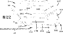
Figure 22 looks from Figure 21 center line 22-22 direction, with the enlarged view of the head of applying ointment or plaster of Figure 20;
Figure 23 is with the enlarged view of the head of applying ointment or plaster of Figure 21 when the 5th position;
Figure 24 is with the enlarged view of the head of applying ointment or plaster of Figure 23 when the 6th position;
Figure 25 is with the enlarged view of the head of applying ointment or plaster of Figure 24 when the 7th position;
Figure 26 is with the enlarged view of the head of applying ointment or plaster of Figure 25 when 8 positions;
Figure 27 is with the enlarged view of the head of applying ointment or plaster of Figure 26 when the 9th position;
Figure 28 is the birds-eye view of head second embodiment of the present invention when primary importance of applying ointment or plaster;
Figure 29 be apply ointment or plaster head when the second place with the birds-eye view of Figure 28;
Figure 30 be apply ointment or plaster head when the 3rd position with the birds-eye view of Figure 29;
The specific embodiment
The same in the accompanying drawings identical parts of number designation representative.
Improved flexible tape applicator of the present invention is labeled as 1, is mainly represented by Fig. 1-4.Applicator 1 comprises that a support 2, one workplatformes 3, one bases 4, a head 5 and of applying ointment or plaster is used for fixing the carriage 6 of a spool 7.
Referring to Fig. 1-4, support 2 is provided with pair of end walls 10 and a pair of vertical with end wall 10 basically sidewall 11.Every sidewall 11 is provided with stull 12 and a lower brace 13 on one and every end wall is provided with a lower brace 14.One vertical column 15 each angle of support 2 be in sidewall 11 on stretch in the middle of stull 12 and the lower brace 13.One additional vertical post 15 (Fig. 3 and 3A) is used for increasing supporting in the middle of being positioned at the two ends of sidewall 11 and going up stull 12 lower braces 13.One strut 16 extends to the position of close lower brace 13 of the post 15 of sidewall 11 ends downwards from the close last stull 12 of the post 15 at every sidewall 11 middle parts.Base 4 is being supported in the last stull 12 of every sidewall 11.
Still referring to Fig. 1-4, the end carriage 20 that workplatform 3 is provided with pair of parallel and separates.Every butt beam 20 is positioned in the middle of two posts 15 and is parallel with the lower brace 14 of end wall 10 and separate.Equally, open and make the curb girder 21 that platform 3 is provided with pair of parallel and separates.Curb girder 21 is fixed on the post 15 and is parallel with the last stull 12 of sidewall 11 and lower brace 13 and separate.A pair of permanent seat 22 is installed on every butt beam 20.
One rectangle roller member 23 is made of pair of parallel and the bar 24 that separates, one end of every bar is fixed on the permanent seat 22, and many parallel and equally spaced 25 centres that are positioned at two bars 24, many rollers that separate 26 are installed in and are used for supporting plane plate 27 on the every axle 25, surface plate 27 can have multiple size and dimension, in a preferred embodiment, it is a glass board, in the following manner by the head 5 of applying ointment or plaster to its effect.
Referring to Fig. 4, guide rail 30 is gone up stull 12 along every and is connected with it at extending longitudinally and by many bolts 31 especially.Similarly, the rack rails 32 with many wheels tooth 33 is gone up stull 12 at extending longitudinally and parallel with guide rail 30 along every.
Sliding beam 34 is supported in the stull 12 and perpendicular basically stretching, extension, and supporting seat 35 is parallel with stull 12 on basically with each end connection and each supporting seat 35 of sliding beam 34.Referring to Fig. 4 and Fig. 7, guide block 36 is installed on each supporting seat 35 by many bolts 37 especially.Each guide block 36 is provided with a groove 38, and this groove and guide rail 30 are complementary relationship, to allow sliding beam 34 in the directionally controlled slip of arrow A indication in Fig. 4 particularly on the guide rail 30.Still referring to Fig. 4 and Fig. 7, first actuating device that is used for moving the head 5 of applying ointment or plaster comprises one first motor 41, and this first motor 41 is supported by many brackets 42 by sliding beam 34.Motor 41 comprises that one has the axle drive shaft 43 (Fig. 6) of connected worm gear 44.
Referring to Fig. 2,4,6 and 7, driven gear 45 is connected with worm gear 44 movable engagements and with axle 46, and this axle 46 is substantially perpendicular to axle drive shaft 43 and stretches.Axle 46 is basically along the total length of sliding beam 34 and pass its two ends and stretch.Axle 46 is supported rotationally by the every end bonded assembly bearing seat 47 with sliding beam 34, and has a miniature gears 48 (Fig. 7) to be installed in each end of spools 46.Miniature gears 48 is installed on the position axle 46 in addition of bearing seat 47, so that bearing seat 47 is along close first motor 41 in position on the length direction of axle 46.In this manner, each miniature gears 48 with rack rails 32 movable engagements so that move sliding beam 34 by the direction of arrow A indication among Fig. 4.Particularly, motor 41 rotates worm gear 44 rotations that make axle drive shaft 43 and interconnection.When worm gear 44 rotated, driven gear 45 rotated the miniature gears 48 that causes axle 46 and interconnection and rotates.When each miniature gears 48 rotated, it produced the direction motion as the arrow A indication respectively with a rack rails 32 engagements.Simultaneously, guide block 36 so that support most of weight of sliding beam 34, and guarantees that sliding beam 34 moves in parallel with last stull 12 basically direction with guide rail 30 interlocks.
Referring to Fig. 1, pair of guide rails 51 is connected with sliding beam 34 by many bolts.Rack rails 52 with many teeth 53 also with sliding beam 34 bolted connections and parallel and in the middle of guide rail 51.Second motor 54 is connected with it by base 4 supportings and by plate 55.Comprise also that referring to Fig. 5 and 8, the first actuating devices one second motor, 54, the second motors 54 comprise an axle drive shaft 56 especially, this axle drive shaft 56 passes plate 55 stretching, extensions and has the miniature gears 57 that is installed on this axle drive shaft.Miniature gears 57 aligns with rack rails 52 and the two movable engagement so that by arrow B (Fig. 5) direction movable base 4.Many guide blocks 58 are installed on the plate 55 and every guide block is provided with a groove 59.Each groove 59 and a guide rail 51 be complementary relationship and with its activity interlock.
Just cause sliding beam 34 when the direction (Fig. 4) of arrow A indication goes up motion at first motor 41, the driving of second motor 54 causes that axle 56 and interconnection miniature gears 57 rotate.When interconnection miniature gears 57 rotates, thereby it meshes with the tooth 53 of rack rails 52 and causes that base 4 moves with respect to sliding beam 34 direction as arrow B indication in Fig. 5 and 9 of arrow A direction in perpendicular to Fig. 4.Similarly, when base 4 and by arrow B (Fig. 5 and 9) when direction moves, one of them interlock of a pair of guide block 58 and pair of guide rails 51 is with supplemental support base 4, and guarantees that base 4 moves in the direction that is parallel to rack rails 52.
Referring to Fig. 1,8 and 10, the first actuating devices also comprise one the 3rd motor 66, and base 4 comprises that one supports on second plate, 65, the three motors of the 3rd motor 66 axle drive shaft 67 and a miniature gears 68 are installed.Some vertical guide rails 69 are connected with second plate 65 with a rack rails 70 parallel with this vertical guide rail 69.A pair of guide block 71 is connected with plate 55.The groove 72 that is complementary relationship with a guide rail 69 is positioned at each guide block 71.
Referring to Figure 10, when the 3rd motor 66 rotated, axle drive shaft 67 and interconnection miniature gears 68 rotated.Like this, the rotation of the 3rd motor 66 causes miniature gears 68 and vertical rack rails 70 movable engagements so that come movable base 4 up and down with respect to workplatform 3 and sliding beam 34.Similarly, when the 3rd motor 66 during at vertical direction movable base 4, guide block 71 and guide rail 69 interlocks are to guarantee that base 4 moves in the direction that is arranged essentially parallel to rack rails 70.
Still referring to Figure 10, a pneumatic actuator 75 is connected with plate 55 at bolt 76 places, is connected with second plate 65 at bolt 77 places.Because base 4 is very heavy, pneumatic actuator 75 auxiliary the 3rd motors 66 are at vertical direction movable base 4, and in case the 3rd motor 66 base 4 has been moved on to and has been used for base for supporting 4 behind the position of selecting in advance.In this manner, the 3rd motor 66 can overload, and owing to recycling the wearing and tearing that produce on miniature gears 68 and the rack rails 70 has been alleviated basically.
As from the foregoing, first motor 41 is by the direction movable base 4 of arrow A indication among Fig. 4 and the head 5 of applying ointment or plaster, and second motor 54 be substantially perpendicular to the arrow A direction as Fig. 5 in the direction of arrow B indication drive.The vertical direction movable base 4 of the 3rd motor 66 arrow C indication in Fig. 5 and the head 5 of applying ointment or plaster are so that drive under cartesian coordinate system.
Referring to Fig. 5, the 4th motor 78 that is installed on the base 4 orders about rotation especially.The 4th motor 78 orders about the head 5 of applying ointment or plaster and rotates as the direction (Fig. 5) of arrow D indication with respect to workplatform 3 and base 4.Motor 78 is installed on the horizontal plate 79 that is supported by base 4 and comprises an axle drive shaft 80, at an end of this axle drive shaft 80 belt pulley 81 is installed.The head 5 of applying ointment or plaster is installed on the base 4 by one 82, and a belt pulley 83 is installed on this axle 82.Driving belt 84 stretches around belt pulley 81 and 83, is driven by motor 78 to cause that axle drive shaft and interconnection belt pulley 81 rotate.Because belt pulley 81 and driving belt 84 frictional connectiones, belt pulley 83 rotates, and causes that hollow shaft 82 and the interconnection head 5 of applying ointment or plaster rotates.
According to a principal feature of the present invention, flexible tape applicator 1 makes the head 5 of applying ointment or plaster move on all directions of cartesian coordinate system with respect to workplatform 3, and the 4th motor 78 is set the head 5 of applying ointment or plaster is rotated with respect to workplatform 3.Obviously know also that by last the present invention can be made under the condition that does not break away from invention essence that operated motor 41,54 and 66 comes mobile working platform 3 rather than the head 5 of applying ointment or plaster.
Referring to the detailed head 5 of applying ointment or plaster that shows of Figure 11-15, the head 5 of applying ointment or plaster is provided with a housing 90 especially.Referring to Figure 11, housing 90 is provided with a vertical the first side wall 91, pair of parallel and the end wall 92 that separates and one second sidewall 93 especially.This second sidewall 93 be provided with a vertical component effect 94 and from vertical component effect 94 to the first side wall 91 bevelled rakes 95.One top board 96 is mounted to and the first side wall 91, and end wall 92 and vertical component effect 94 are vertical and have a cylinder sleeve protruding 97 that is stretched upwards by top board.Belt pulley 83 is supported on the cylinder sleeve protruding 97.
First roller member 99 is installed near on the roof 96 of the first side wall 91, and comprises the L shaped bracket 100 (Figure 11,12 and 14) that pair of parallel separates and stretch downwards.Deflector roll 101 is installed on the axle of L shaped bracket 100 centres that separate on one.And pair of parallel and the last deflector roll 103 that separates are overhanging so that be with 144 to engage rotationally with soft to the first side wall 91 from L shaped bracket 100.Roller member tilts with respect to the first side wall 91.
One cylinder 111 is installed on the first side wall 91 and comprises a piston rod 112.A pair of swivel arm is installed in an end of piston rod 112, and every swivel arm 113 is installed in rotation on the scissors blade 115 by a rotational pin 114.
According to another characteristics of the present invention, a cylinder 120 (Figure 13) is installed on the inclination angle parts 95 of second sidewall 93 and comprises that one is installed in the cylinder piston rod 121 on the geometrical clamp 122.One printer 123 is installed in the geometrical clamp 122 and stretch for 144 times towards soft being with the working end, will describe this below.Printer 123 can have multiple size and structure, and it comprises heat-sensitive type printer and ink-jet printing device, and the ink-jet printing device uses in a preferred embodiment.One sliding bar 124 outwards stretches and parallel with inclination angle parts 95 basically and be incorporated in the hole in the sliding shoe 145 from geometrical clamp 122.Like this, cylinder 120 makes printer 123 shift to and move apart under sliding bar 124 and sliding shoe 125 engagement states and softly is with 144, and is parallel with the inclination angle parts 95 of second sidewall 93 basically to guarantee moving of printer 123.Control unit 119 is set so that drive printer 123 at the preset distance place of the stroke of the head 5 of applying ointment or plaster, its purpose will describe in detail below.
One second cylinder 126 is installed on the inclination angle parts 95 of second sidewall 93, and comprises one by pivot pin 128 and a permanent seat 129 bonded assembly piston rods 127.When second cylinder 126 is done the time spent, a sliding bar 131 moves in guide block 132 so that guiding permanent seat 129, and guide block 132 is installed on the inclination angle parts 95.Permanent seat 129 is supporting one and can keep vertical substantially driven voller or compress pin roll 130 from the outside stretching, extension of this permanent seat and when second cylinder 126 stretches.
One the 3rd cylinder 133 is installed on the inclination angle parts 95 of second sidewall 93 and comprises a piston rod 134.Piston rod 134 is connected with permanent seat 136 at pivot pin 135 places.Similar with permanent seat 129, when cylinder 133 is done the time spent, sliding bar 131 moves so that guide permanent seat 136 with guide block 132, and guide block 132 also is installed on the inclination angle parts 95.One servo-actuated or hold-down roller 137 are installed on the permanent seat 136.
Referring to Figure 13 and 15, many cylindrical shafts stretch downwards from the head 5 of applying ointment or plaster.The front is described and has been represented two flower wheels, driven voller 137 and driven voller 130 by the long and short dash line among Figure 15.Other roller is installed on the axle that passes lower plate 138 stretching, extension downwards, and lower plate 138 is provided with some interconnected pores 139 that pass it.Second actuating device comprises one second CD-ROM drive motor 140, and this second CD-ROM drive motor 140 (Figure 14) is installed on the lower plate 138 and comprises an axle drive shaft 141 (Figure 15), and a gear 142 and a roller 143 are installed on this axle drive shaft 141.Roller 143 and softly be with 144 to fit.Driven gear 142 and ring gear 150 engagements that are installed on one 151, so driven gear 142 anticlockwise direction rotation causing ring gear 150 clockwise directions rotate.Ring gear 150 that clockwise direction rotates and first roller-dear, 152 engagements that are installed on one 153.The ring gear 150 that anticlockwise direction rotates causes that first roller-dear 152 rotates at anticlockwise direction.Thereby first roller-dear 152 be installed in second ring gear 155 on one 156 and be rotationally connected and cause that second ring gear 155 rotates at anticlockwise direction.Second ring gear 155 be installed on one 158 and second roller-dear 157 that rotates at anticlockwise direction is rotationally connected.Driven voller 159 is installed on the axle 153 and 158 so that roller 143 and 159 all rotates (Figure 15) at anticlockwise direction.From Figure 13 and 15, see too clearly, gear 142,150,152,155 and 157 are contained in the interconnected pores 139 of lower plate 138.From Figure 15, also can see too clearly, non-driven voller 130 and 137 and the spacing of driven voller 159 equal soft with 144 width.
Still referring to Figure 13 and 15, vertical pressure roller 162 is installed in non-driven voller 130 and 137 and the centre of driven voller 159 and equal soft with 144 height with the spacing of surface plate 27.Vertical pressure roller 162 to soft with 144 apply a downward power with the district 145 that guarantees to apply ointment or plaster in and surface plate 27 evenly paste.Particularly pressure roller 162 is installed in the sliding bar driven member 108 that engages with a pair of sliding bar 109.Cylinder 160 also be installed on the first side wall 91 and comprise one with pressure roller 162 bonded assembly piston rods 161.Constant Pneumatic pipe cleaner cross cylinder 160 and piston rod 161 be applied on the pressure roller 162 with guarantee in the district 145 of applying ointment or plaster to soft with 144 apply a constant downward power with guarantee soft be with 144 and surface plate 27 firmly paste.And, being provided with when regulating blocking device 110 and moving with respect to sliding bar 109 by cylinder 160 with convenient sliding bar driven member 108, it may be locked in needs the position.
According to a principal feature of the present invention, carriage 6 is installed in the top of base 4, particularly on the hollow shaft 82, so that carriage 6 is installed in the top of axle 82.And the head 5 of applying ointment or plaster is installed in the bottom of axle 82.Because the axle drive shaft 82 of the 4th motor 78 rotates, cause that like this apply ointment or plaster head 5 and carriage 6 all rotate.
Referring to Figure 16 and 17, the plate 163 that carriage 6 is provided with pair of parallel and separates, it also is included in a preceding backing roll 164 and a back backing roll 165 that stretches between this plate.Backing roll 164 and 165 is supporting be provided with a pair of end plate 176 soft with 144 spool 166.Second actuating device also comprises one first CD-ROM drive motor 167, and this first CD-ROM drive motor 167 is connected with a plate 163 and stretches in the middle of spool 166 upper plates 163.Motor 167 comprises that one is equipped with the axle drive shaft 168 (Figure 17) of a driving pulley 169 on it.Driven pulley 172 and back support that roller 165 is connected and with driving pulley 169 on a plane.First assembly pulley 173 be connected with plate 163 and with driving pulley 169 and driven pulley 172 on a plane.One first feed belt 174 stretches around driving pulley 169 and driven pulley 172, and the power that applies by first assembly pulley 173 keeps tension force.The driving of motor 167 makes axle drive shaft 168 and interconnection driving pulley 169 rotate.When driving pulley 169 rotated, first feed belt 174 made driven pulley 172 and interconnection back backing roll 165 rotate with driven pulley 172 frictional connectiones.Back backing roll 165 engages with the end plate 176 of spool 166 and has caused that spool 166 rotates.One bearing set 177 is installed on the plate 163 and comprises that one is installed in rotation on the axle 178 in it.One driven pulley 179 and a negative pulley wheel 180 are installed on one 178 and separate to allow a plate 181 to be placed on therebetween.One second groove that second feed belt 182 forms on belt pulley 172 and driven pulley 179 stretches, and second feed belt 182 is by keeping tension force with assembly pulley 183 mutual actions.Like this, the rotation of driven pulley 172 causes that belt pulley 179 is that axle 178 and interconnection negative pulley wheel 180 rotate then.
The 3rd feed belt 188 stretches with negative pulley wheel 180 frictional connectiones and around a bearing seat 189 and a belt pulley 190.Belt pulley 190 is installed on the take-up spool 191 (Figure 16) and is used for reeling from soft with the paper gasket band of peeling off 192.Obviously as can be known, the driving of motor 167 makes driven pulley 172 and interconnection back backing roll 165 rotate from Figure 16 and 17.Because end plate 176 frictional connectiones of back backing roll 165 and spool 166, the driving of motor 167 makes spool 166 rotate, similarly, by motor 167, first feed belt 174, the interconnection of second feed belt 182 and the 3rd feed belt 188, the driving of motor 167 also make take-up spool 191 to rotate with the proportional speed of the rotating speed of spool 166, guaranteed that therefore paper tape 192 is wound on the take-up spool 191 with the proportional speed of peeling off from spool 166 with soft band of speed.
Once back deflector roll 200 soft be positioned at before entering in the hollow shaft 82 with 144 soft with 144 two.Back deflector roll 200 also is with 144 to import in the hollow shaft 82 with soft.And a sensor 201 is installed near cylinder 196 places and is used for measuring piston rod 197 mutually in the side-play amount of cylinder 196.Particularly, softly be with 144 under tension force, to involve and cross bearing roller 198 and middle deflector roll 199 from spool 166.Tension force is big more, and the pressure that is applied to piston rod 197 more ambassador's piston rod 197 deeper inserts in the air cylinder 196.
When soft with 144 carriages 6 of packing on the spool 166 in the time, soft path with 144 starts from flexible tape applicator 1.Soft then band is pulled out from spool 166, and paper gasket band 192 separates with soft band and is wrapped in separately on the take-up spool 191.Then, softly be with 144 by between the deflector roll 199 and cross bearing roller 198.Soft band passes back deflector roll 200 then vertically downward and enters the inside (Fig. 1,5,16 and 17) of hollow shaft 82.Softly come out from the inside of hollow shaft 182, walk around the centre (Figure 11 and 12) of deflector roll 101 and top roll 103 again with 144.Softly rotate so that soft Width with 144 contacts (Figure 11-14) with last deflector roll 101 around its longitudinal axis with 144.Softly pass lower guide roll 107 then so that soft edge with 144 contacts with the outside face of deflector roll 107 with 144.When passing lower guide roll 107, soft engage with lower guide roll 106 and spend in the scopes of 20 degree with 144 10 rotate, be preferably in 25 and spend and rotate in the scopes of 60 degree so that soft, and the edge of soft band contacts (Figure 11-14) with surface plate 27 with 144 the wideest surperficial perpendicular.
Referring to Figure 12,13 and 15, softly be with 144 to walk around roller 143, and driven voller 130 and 137 and the centre of driven voller 159.Driven voller 159 and driven voller 130 position intermediate in the district of applying ointment or plaster softly are with 144 to place on the surface plate 27.In order to help to be with 144 to apply ointment or plaster on surface plate 27 with soft, pressure roller 162 places the centre of driven voller 130 and driven voller 159.The spacing distance of pressure roller 162 and surface plate 27 equal substantially soft with 144 height so that apply a downward power with 144 and evenly paste with surface plate guaranteeing to soft at the pressure roller 162 of applying ointment or plaster.From Figure 15 and 16, can recognize, softly drive along its whole circuitous mobile route by carriage 6 with 144.And motor 140 is by interconnection gear 142,150,152, thus 155 and 157 come driven roller 143 and 159 drive soft with 144 near with the applying ointment or plaster a little of surface plate 27.Since soft be with 144 driven voller 130 and 137 with driven voller 159 between be squeezed, roller 143 and 159 has guaranteed softly to be with 144 to drive in the district of applying ointment or plaster and the edge makes a circulation mobile route by the head 5 of applying ointment or plaster.
As mentioned above, carriage 6 is installed in the top of axle 82, and the head 5 of applying ointment or plaster is installed in the bottom of axle 82 so that first motor 41, the second motors, 54, the three motors 66 and the 4th motor 78 drive apply ointment or plaster head 5 and carriage 6 under cartesian coordinate system.Like this, soft with 144 path keep constant and soft be with 144 with higher rate consistently and under effective control to surface plate 27 feeds.
According to another characteristics of the present invention, the applying ointment or plaster district between driven voller 130 and the driven voller 159 with apply ointment or plaster head 5 and carriage 6 with respect to the center shaft of the rotation of base 4 in line, this rotates by the 4th motor 78 and drives.Apply ointment or plaster head 5 center of turn and soft can not produce when guaranteeing applying ointment or plaster a little in line on the surface plate 27 with 144 because the head 5 of applying ointment or plaster rotates with respect to surface plate 27 in work soft with 144 angular variation.
Now described softly with 144 mobile routes by flexible tape applicator 1, its method of operation will be described referring to Fig. 1-4 and 18-28 especially.At first referring to Fig. 1-4, motor 41 drives base 4 and moves with the head 5 arrow A direction in Fig. 4 of applying ointment or plaster, second motor 54 drives base 4 and moves with the head 5 arrow B direction in the Fig. 5 that is substantially perpendicular to the arrow A direction of applying ointment or plaster, and the 3rd motor 66 drives base 4 and the head 5 of applying ointment or plaster moves to the direction perpendicular to workplatform 3 and surface plate 27.The 4th motor 78 drives the head 5 of applying ointment or plaster especially as shown in Figure 5 and rotates with respect to base 4.
Referring to Figure 18, in the starting position, the head 5 of applying ointment or plaster is positioned at the top of surface plate 27, in this position, soft be with 144 with surface plate 27 separate a bit of distance.Then, the 3rd motor 66 orders about the head 5 of applying ointment or plaster and moves vertically to a position among Figure 19 in Figure 18 arrow D direction, this position be soft with 144 place driven voller 130 and 137 and driven voller 159 between the position of glass top.Then, first motor 41 drives the head 5 arrow E direction in Figure 20 particularly of applying ointment or plaster and moves.When applying ointment or plaster head 5 when the arrow E direction moves, motor 140 continuous handling driven vollers 143 and 159, at this moment, motor 167 rotates spool 166.Similarly, pressure roller 162 between driven pin roll 130 and the driven voller 159 soft with 144 apply ointment or plaster a little on exert pressure with guarantee soft be with 144 with surface plate 27 bonding.
When arriving the 4th angle, softly place on the surface plate 27 so that provide an envelope band around the whole periphery of surface plate 27 with 144 positions by the alphabetical A indication in Figure 19 and 20.Yet, because driven voller 137 is with 144 to contact with driven pin roll 130 with soft, so they must place the inside of the continuous hoop member of soft band.Therefore, if the head of applying ointment or plaster moves continuously in the direction of Figure 23 indication particularly, roller 130 and 137, and printer 123 will contact with soft first with 144, and disengaging surface plate 27.
Especially referring to Figure 24, cylinder 133 orders about piston rod 134 retractions, when piston rod 134 retractions, sliding bar 131 moves in the groove of the complementary shape that forms on the guide shoe 132, to guarantee that permanent seat 136 moves being parallel to piston rod 134 travels direction keeping under the vertical substantially state, piston rod 134, the permanent seat 136 of interconnection and driven voller 137 move so that promote above with 144 upper limb soft fully in vertical direction, and this can be especially referring to Figure 24.
When driven voller 137 arrived position shown in Figure 24, second motor 54 drove the head 5 arrow G direction in Figure 25 particularly of applying ointment or plaster and moves.After this, piston rod 134 is from cylinder 133 retractions, thereby sliding bar 131 outwards stretches permission deflector roll 137 arrival position shown in Figure 25 from guide shoe 132 thus.After this, second cylinder 126 upwards promotes piston rod 127, interconnection permanent seat 129 and pin roll 130 in a kind of essentially identical mode, and this pushing course finishes when cylinder 133 drives driven voller 137.When second air cylinder 126 drove once more, sliding bar 131 moved in the guide shoe 132 so that guiding permanent seat 129 and the driven pin roll 130 of interconnection move to position shown in Figure 25 along suitable mobile route.
In case after the driving of driven voller 130 by second cylinder 126 moved to position shown in Figure 25, second motor 54 drove the head 5 arrow G direction in Figure 26 of applying ointment or plaster once more and moves.In case driven pin roll 130 moves to soft with below 144 the edge, driven pin roll 130 promptly moves to position shown in Figure 26.After this, second motor 54 drives the head 5 arrow G direction in Figure 27 of applying ointment or plaster once more and moves and move to the just in time position below the edge of surface plate 27 of blade 115.After this, thus cylinder 111 piston rod 112 and interconnection pivot arm 113 make blade near and cut off and softly be with 144, this is illustrated among special Figure 27.After this, motor 140 and 167 counter-rotatings move on to starting position shown in Figure 180 until soft with 144, and the head 5 of applying ointment or plaster in this position can move once more so that restart is with 144 to be placed on the surface plate 27 soft.The effect of printer 123 by cylinder 120 be same removable to be left and softly is with 144.
With 144 in the application process of surface plate 27, printer 123 is along the equidistant printing mark in soft the inside with 144 soft.One of them of these signs is illustrated in especially among Figure 27 and with Reference numeral 203 and refers to, and the some position of arranging muntin when dividing optical window is made in its representative.By driving printer 123 soft the applying ointment or plaster when identifying 203 of passing the head 5 of applying ointment or plaster, this plaster application method can produce different signs with being with 144 equal intervals when only.Particularly, owing to utilize one section softly to be with 144 to form each angle, this soft quantity with 144 will be offset equidistant sign 203 so that the signs that are used on each angle will be offset owing to this soft quantity with 144 of generation.Therefore, printer 123 can not come mark according to the quantity of the soft band that passes a unit, but comes mark moving one before being with the sign 203 of applying ointment or plaster on 144 and determine distance to soft to guarantee printer according to surface plate.By this way, on soft all four limits that will be arranged in surface plate 27 with the mark 203 that forms on 144 accurately to guarantee that muntin placed on it accurately at interval.Control unit 119 receives the information of moving distance about the preliminary election of the miles of relative movement of the head 5 of applying ointment or plaster, and order about printer 123 and move with predetermined interval along the mobile route of the head 5 of applying ointment or plaster, also note that various out of Memory can be applicable to soft being with, for example under the prerequisite that does not break away from essence of the present invention from the producer and client's information.And, should be noted that trellis sign can apply ointment or plaster on workplatform 3, under the prerequisite that does not break away from essence of the present invention, use a sensor to read trellis sign and along the trellis sign that forms on the workplatform 3 by the desired location to soft 144 signs 103 of applying ointment or plaster of being with.
Owing to some incidents, need to change the speed of motor 167.Particularly, with every pull-up of 144 during from spool 166, the girth of spool has also reduced when soft.When soft girth with every circle of 144 diminished, the spool 166 soft band quantity that breaks away from that whenever turns around also reduced.Thereby thereby the speed of motor 167 must increase so that change from spool 166 more and breaks away from the soft band of multiturn more to reach each given soft strip length.On the other hand, when the head 5 of applying ointment or plaster changeed an angle, motor 167 was answered feed soft band seldom, only needed soft band seldom and needed a large amount of time because form this angle.
Like this, dancer arm device 195 has produced a pressure incoming signal that is read by sensor 201, when dancer arm device 195 is positioned at position shown in Figure 17 long and short dash line, promptly when being with 144 more for a long time from spool 166 the soft of expansion than common motor 167 near the motor 140 of applying ointment or plaster a little, soft bigger with the pressure on 144, this moment, described pressure incoming signal was used for increasing soft with 144 supply by motor 167 feeds.On the other hand, dancer arm device 195 can produce a signal that is read by sensor 201, and many soft bands of these signal indication motor 167 feeds and motor 140 do not use the soft band that launches from spool 166.To the slow down speed of motor 167 of this pressure incoming signal is identical with 140 speed until motor 167.
Second embodiment of the present invention is typically expressed as 250, and identical with flexible tape applicator 1, and it comprises the base 252 identical with base 2, workplatform 253, one bases 4 identical with workplatform 3, the head 5 of applying ointment or plaster, carriage 6 and spool 7.Yet base 252 and workplatform 253 and sliding beam 254 are bases 2, the twice of the width of workplatform 3 and sliding beam 34.Referring to Figure 28, workplatform 253 have two supply units 253 ', just first conveyer and second conveyer, each supply unit 253 ' support a pane respectively, A and A ', just first plate and second plate.Figure 28 represents softly to be with 144 to apply ointment or plaster on surface plate A and the head 5 of applying ointment or plaster is being applied ointment or plaster to surface plate A ' and softly is with 144.Apply ointment or plaster softly when being with 144 to surface plate A ' when the head 5 of applying ointment or plaster, surface plate A removes and surface plate A ' moves on to correct position soft 144 (Figure 29) that are with that apply ointment or plaster subsequently from workplatform 253.Soft applied ointment or plaster on surface plate A ' with 144 after it again in Figure 30 particularly the direction shown in the arrow A remove and the head 5 of applying ointment or plaster moves to surface plate A that " go up work, this surface plate A " moves to correct position in advance at soft band when surface plate A ' applies ointment or plaster." when applying ointment or plaster, a plate A who replenishes moves to correct position to replace A ' and the applying ointment or plaster of the head 5 of accepting to apply ointment or plaster to be with 144 to surface plate A soft.
Can see from second embodiment of the present invention, when surface plate can move into and shift out flexible tape applicator 250 and the head 5 of applying ointment or plaster is applied ointment or plaster softly when being with 144 continuously to a surface plate, surface plate moves into the speed that shifts out flexible tape applicator 1 and has reduced with comparing basically from first embodiment of the present invention on workplatform 253.
In a word, flexible tape applicator 1 is provided with a base 2, one workplatformes 3, apply ointment or plaster a head 5 and a carriage 6.Apply ointment or plaster head 5 and carriage 6 all supported and is connected to each other together by a base 4 and move.Be provided with that some motors are used for ordering about bearing 6 and the head 5 of applying ointment or plaster moves under cartesian coordinate system with respect to workplatform 3, the 4th motor 78 makes the head 5 of applying ointment or plaster rotate with respect to base 4.Order about close soft the 5th motors 167 of applying ointment or plaster a little at the 6th motor 140 and be used for rotating a spool 166 with 144 settings when surface plate moves.Soft band is walked around the data-capture unit that comprises dancer arm device 195 with a cylinder bonded assembly.Or the pressure on the cylinder or piston rod form one and act on the relevant simulation signal of force value on the dancer arm device with soft band through measuring with respect to the position of cylinder, and this analog signal is sent to a first control device or control unit from a sensor 201 and makes the speed increase of when the pressure on the dancer arm device 195 increases the 5th motor 167 to control the 5th motor 167.On the contrary, if the speed of the 5th motor 167 reduces when the pressure on the dancer arm device 195 reduces, like this, the pressure that is applied on the dancer arm device 195 is directly related with the soft quantity with 144 of applying ointment or plaster on surface plate 27.
When applying ointment or plaster a continuous soft band to a surface plate, some cylinders order about roller and move on both sides can not make unintentionally with the head that guarantees to apply ointment or plaster and softly be with 144 to separate with surface plate 27.
In an alternative embodiment, the width of the workplatform of setting is enough to make an independent head of the applying ointment or plaster polylith plate 27 of applying ointment or plaster on this workplatform, and when the head of applying ointment or plaster was worked on an original plate, a new surface plate moved to suitable position.
Therefore, improved flexible tape applicator is simple in structure, and it provides one feasible, safety, low cost and equipment efficiently, and this equipment has reached all purposes of enumerating, has overcome the difficulty that existing equipment runs into, and has solved these problems, and has obtained some new effects.
In describing in front, used the succinct wording of knowing and being convenient to understand, but it is not limited in the scope of prior art, so therefore these wording are tending towards briefly explaining just in order to describe.
And the present invention describes and illustrates by embodiment, and scope of the present invention is not limited in the description of details.
Characteristics of the present invention, discovery and the principle described proposed in claims, the mode that improved flexible tape applicator is set up and used, architectural feature and advantage, the new suitable effect that obtains, the new structure, device, parts, layout and the combination that are suitable for.
Claims (38)
1. one kind is used for to the apply ointment or plaster applicator of soft band of a plate, and it comprises:
One base;
One by this base support and have the head of applying ointment or plaster of a mobile route, and the path of a soft band to small part is passed this apply ointment or plaster a head and soft strip laying stuck district;
Be suitable for remaining close to a workplatform of the plate of described base;
Be used for predetermined speed along first actuating device of described mobile route with respect to the described head of applying ointment or plaster of movement of objects;
Be used for ordering about second actuating device of soft band by what the described head of applying ointment or plaster carried along the path movement of soft band;
Be used for collecting data-capture unit with the data of the velocity correlation of first actuating device; With
The first control device that is rotationally connected with second actuating device, this first control device be used for accepting data-capture unit data, change the speed of second actuating device and make the speed of second actuating device operation and the speed of first actuating device operation keep a proportionate relationship according to the data of described collection, therefore the tension force of soft band keeps substantially constant on the whole mobile route of the head of applying ointment or plaster.
2. applicator as claimed in claim 1 is characterized in that bracing or strutting arrangement comprises pair of parallel and the stull that separates and a sliding beam that is supported by this stull; The head of wherein applying ointment or plaster is supported by described sliding beam.
3. applicator as claimed in claim 2 is characterized in that workplatform is positioned at the centre of stull and below the head of applying ointment or plaster.
4. applicator as claimed in claim 3 is characterized in that workplatform is level basically.
5. applicator as claimed in claim 2, it is characterized in that first actuating device comprises is used for making first motor that head moves in the direction that is parallel to stull of applying ointment or plaster, be used for making second motor that head moves in the direction perpendicular to stull and be used for making three motor of head of applying ointment or plaster of applying ointment or plaster with respect to the workplatform vertical shifting.
6. applicator as claimed in claim 5 is characterized in that at least one rack rails is parallel to stull and stretches; Wherein first motor comprises an axle drive shaft; One miniature gears link to each other with this axle drive shaft and with the movable engagement of described rack rails so that be used for making the head of applying ointment or plaster to move in the direction that is parallel to described stull; At least one rack rails stretches perpendicular to stull, and wherein second motor comprises an axle drive shaft; One miniature gears link to each other with this axle drive shaft and with the movable engagement of described rack rails so that be used for making the head of applying ointment or plaster to move in direction perpendicular to described stull.
7. applicator as claimed in claim 1 is characterized in that second actuating device comprises and is fit to first CD-ROM drive motor of the soft band of head feed of applying ointment or plaster and drives second CD-ROM drive motor of soft band along soft belt path.
8. applicator as claimed in claim 7 is characterized in that it also comprises a carriage of the spool that is used for supporting soft band; Wherein first CD-ROM drive motor by described bearing bracket second CD-ROM drive motor by the described head supporting of applying ointment or plaster.
9. applicator as claimed in claim 8 is characterized in that base is by the described head supporting of applying ointment or plaster.
10. applicator as claimed in claim 7, it is characterized in that described data-capture unit comprises a dancer arm and is used to refer to the position control that described dancer arm departs from, this dancer arm be fit to contact with soft band and with soft with on tension variation be offset; Described first control device is got in touch with described position control activity so that receive with described dancer arm and is departed from relevant data, therefore described dancer arm causes that in departing from of a direction described control setup increases the speed of second actuating device operation, and described dancer arm causes that in departing from of other direction first control device reduces the speed of second actuating device operation.
11. applicator as claimed in claim 10 is characterized in that first control device is electrically connected so that increase and reduce the speed of first CD-ROM drive motor with first CD-ROM drive motor of second actuating device.
12. applicator as claimed in claim 11 is characterized in that dancer arm is loaded on the head of applying ointment or plaster along soft belt path.
13. applicator as claimed in claim 12, it is characterized in that described position control comprises a cylinder and a piston, therefore cylinder is connected with dancer arm with one of piston, and departing from of described dancer arm causes described cylinder and piston one of them moves with respect to cylinder and piston one of other so that change pressure in the cylinder; And described position control comprises that also the device for pressure measurement that is used for measuring the pressure that produces in the cylinder is to determine the deviation value of described dancer arm.
14. applicator as claimed in claim 12, it is characterized in that described position control comprises a cylinder and a piston, cylinder and one of piston and degree of tightness are regulated support and are connected, and therefore described degree of tightness is regulated departing from of support and caused described cylinder and piston one of them cylinder and piston mobile with respect to other; And described position control comprises that also the measurement mechanism that is used for measuring the accurate distance that piston moves regulates the deviation value of support to determine described degree of tightness.
15. applicator as claimed in claim 7 is characterized in that some rollers are positioned at the front portion near the district of applying ointment or plaster.
16. applicator as claimed in claim 15, at least one roller that it is characterized in that distinguishing near applying ointment or plaster is by second drive motor.
17. applicator as claimed in claim 16, it is characterized in that at least one roller be used for bouncing back described soft with on a restoring device of described roller link to each other.
18. applicator as claimed in claim 17 is characterized in that described restoring device is a cylinder; Described cylinder have the piston rod that links to each other with a roller at least be used for bouncing back described soft with on a roller.
19. applicator as claimed in claim 18, it is characterized in that a hold-down roller be positioned near and with each driven voller position spaced, described soft band is between driven voller and hold-down roller.
20. applicator as claimed in claim 19 is characterized in that a pressure roll device is used for adding a downward power to described soft band application between driven voller and hold-down roller.
21. applicator as claimed in claim 20 is characterized in that being provided with a pressure apparatus and is used for applying a downward power to pressure roll.
22. applicator as claimed in claim 15 is characterized in that a printing device is used for to described soft strip laying stuck one muntin sign by the described head loading of applying ointment or plaster.
23. applicator as claimed in claim 22 is characterized in that therefore described printing device is loaded by the described head of applying ointment or plaster after some rollers that described printer prints after described soft band passes described roller on this soft being with.
24. applicator as claimed in claim 23 is characterized in that described printer is adapted at the described soft printing of being with when described soft band is positioned on the described surface plate.
25. applicator as claimed in claim 24 is characterized in that it also comprises to be used for measuring the described head of applying ointment or plaster with respect to the miles of relative movement of described workplatform and be used for ordering about the second control device that described printer moves on respect to the preset movement distance of described workplatform at the described head of applying ointment or plaster.
26. applicator as claimed in claim 25 is characterized in that described restoring device is connected with described printer so that make described printer shift to and shift out described surface plate.
27. applicator as claimed in claim 9 is characterized in that one is stretched between the head at described base and described applying ointment or plaster; This rotation makes described base and the described head of applying ointment or plaster rotate; One motor and the collaborative work of described axle are in order to rotate this axle.
28. applicator as claimed in claim 27 is characterized in that described soft band passes described axle from described carriage and arrives the described head of applying ointment or plaster.
29. applicator as claimed in claim 10 is characterized in that described soft belt path lasts till the described district of applying ointment or plaster from described dancer arm.
30. to the apply ointment or plaster method of soft band of plate, it comprises the steps:
The head of applying ointment or plaster that has soft belt path along predetermined path movement one, simultaneously with predetermined speed to the described plate soft band of applying ointment or plaster;
Measurement along soft belt path soft with on tension force and produce a tension signal;
Tension signal is sent to a control unit;
One soft band actuating device is set to be used for ordering about described soft band when applying ointment or plaster described soft band to described plate and to move to the described head of applying ointment or plaster; And
Control the speed of soft band actuating device by control unit so that make the work speed of soft band actuating device keep a proportionate relationship according to described tension signal in predetermined speed, therefore, described soft with on tension force in the whole mobile route of the described head of applying ointment or plaster, keep substantially constant.
31. method as claimed in claim 30, it is characterized in that it also comprise the following steps: to determine when described soft band is walked around a dancer arm described soft with on tension force; Determine the side-play amount of described dancer arm; And the direct speed that changes described soft band actuating device according to the side-play amount of described dancer arm.
32. method as claimed in claim 31 is characterized in that it also comprises the following steps: to provide a motor as soft band actuating device to be used for rotating the spool of soft band; Described dancer arm is placed motor and the applying ointment or plaster between the district that is used for driving described spool along soft belt path; And the speed of revolution spool increases when the side-play amount that records increases, when the offset minus that the records speed minimizing of revolution spool after a little while.
33. method as claimed in claim 32 is characterized in that its step also is included in soft band and print muntin by a printer on described soft being with after placing on the described plate and identify.
34. method as claimed in claim 33 is characterized in that it also comprises the following steps: to determine and have the miles of relative movement of head with respect to described plate of applying ointment or plaster of a mobile route; And order about printer and print muntin sign with respect to described plate with preset distance along the mobile route of the head of applying ointment or plaster.
35. method as claimed in claim 34 is characterized in that it also comprises the following steps: to be provided with some rollers of distinguishing near applying ointment or plaster; Retraction one of them described roller at least passes through described soft band to allow this roller.
36. method as claimed in claim 35 is characterized in that its step also comprises the driving roller in one of them close district of applying ointment or plaster at least.
37. method as claimed in claim 31 is characterized in that it also comprises the following steps: to promote the described head of applying ointment or plaster before forming one jiao on described soft being with; When the part of described soft band is supported on described surface plate top by the described head of applying ointment or plaster, form one jiao; Replace established angle by falling the described head of applying ointment or plaster.
38. method as claimed in claim 31 is characterized in that it also comprises the following steps: to be provided with first conveyer and one second conveyer below the described head of applying ointment or plaster; First plate and second plate are set on described first conveyer and second conveyer; The soft band of applying ointment or plaster on one of them of first plate and second plate is removed wherein another piece of first plate and second plate simultaneously from corresponding conveyer; Wherein another piece of described first plate and second plate is replaced with the 3rd plate, continue simultaneously on described first plate and second plate to paste soft band so that subsequently by the described head of the applying ointment or plaster soft band of applying ointment or plaster.
Applications Claiming Priority (3)
| Application Number | Priority Date | Filing Date | Title |
|---|---|---|---|
| US547,589 | 1990-06-29 | ||
| US54758995A | 1995-10-24 | 1995-10-24 | |
| US547589 | 1995-10-24 |
Publications (2)
| Publication Number | Publication Date |
|---|---|
| CN1154327A CN1154327A (en) | 1997-07-16 |
| CN1086353C true CN1086353C (en) | 2002-06-19 |
Family
ID=24185265
Family Applications (1)
| Application Number | Title | Priority Date | Filing Date |
|---|---|---|---|
| CN96121951A Expired - Fee Related CN1086353C (en) | 1995-10-24 | 1996-10-24 | flexible tape applicator and method of operation |
Country Status (7)
| Country | Link |
|---|---|
| EP (1) | EP0770754B1 (en) |
| JP (1) | JPH09290956A (en) |
| CN (1) | CN1086353C (en) |
| AU (1) | AU7039296A (en) |
| CA (1) | CA2188624C (en) |
| DE (1) | DE69629345T2 (en) |
| MX (1) | MX9605080A (en) |
Families Citing this family (15)
| Publication number | Priority date | Publication date | Assignee | Title |
|---|---|---|---|---|
| US6868884B2 (en) * | 2001-11-01 | 2005-03-22 | Ged Integrated Solutions, Inc. | Method and apparatus for applying optical film to glass |
| US7063757B2 (en) | 2004-01-08 | 2006-06-20 | Ged Integrated Solutions, Inc. | Method and apparatus for applying optical film to glass |
| US7343953B2 (en) * | 2004-05-28 | 2008-03-18 | United Parcel Service Of America, Inc. | Method and application for applying labels on surfaces of selected surfaces of varying orientations |
| US7105068B2 (en) | 2004-08-20 | 2006-09-12 | Ged Integrated Solutions, Inc. | Method and apparatus for applying aligned tape patterns |
| US7195824B2 (en) | 2004-08-20 | 2007-03-27 | Ged Integrated Solutions, Inc. | Decorative tape |
| ITTV20040117A1 (en) * | 2004-10-20 | 2005-01-20 | For El Base Di Vianello Fortun | AUTOMATIC MACHINE FOR THE APPLICATION OF SPACER PROFILE ON GLASS SHEET AND AUTOMATIC PROCEDURE FOR THE APPLICATION OF SPACER PROFILE ON GLASS SHEET. |
| EP2011757A1 (en) * | 2008-04-02 | 2009-01-07 | Lemuth GmbH | Placing unit and method for fitting a band |
| EP2291574B1 (en) * | 2008-06-19 | 2015-05-20 | Rolf Broszat | System for gluing glass panes into frame profiles |
| US9765564B2 (en) | 2013-03-14 | 2017-09-19 | Ged Integrated Solutions, Inc. | Automated spacer frame fabrication and method |
| CN103662224B (en) * | 2013-12-30 | 2015-06-17 | 青岛汇益包装彩印有限公司 | Automatic labelling device |
| CN110092236B (en) * | 2019-04-23 | 2024-03-08 | 苏州领裕电子科技有限公司 | Keyboard glue aluminum foil transfer device |
| CN110353891B (en) * | 2019-07-19 | 2021-07-30 | 四川大学华西医院 | A device of applying ointment or plaster for transparent applying ointment or plaster |
| CN111013901B (en) * | 2019-12-10 | 2021-07-13 | 深圳先进技术研究院 | Flexible sensor manufacturing equipment and manufacturing method of flexible sensor |
| CN112896669A (en) * | 2021-01-13 | 2021-06-04 | 广东友力智能科技有限公司 | Mattress cornerite rigging machine |
| CN113800314B (en) * | 2021-09-26 | 2022-08-30 | 浙江大华技术股份有限公司 | Membrane paper compounding method and system |
Citations (3)
| Publication number | Priority date | Publication date | Assignee | Title |
|---|---|---|---|---|
| US4328061A (en) * | 1977-10-25 | 1982-05-04 | Haggar Company | Apparatus for depositing adhesive strips |
| US4557783A (en) * | 1983-12-05 | 1985-12-10 | Cincinnati Milacron Inc. | Composite tape laying machine and method |
| US5045146A (en) * | 1989-06-08 | 1991-09-03 | Tremco, Inc. | Tape applicator with corner forming device |
Family Cites Families (13)
| Publication number | Priority date | Publication date | Assignee | Title |
|---|---|---|---|---|
| US3886113A (en) | 1972-09-01 | 1975-05-27 | Air Prod & Chem | Metal-amine complex accelerator for polyester resin curing |
| FR2287278A1 (en) | 1974-10-10 | 1976-05-07 | Saint Gobain | PROCESS AND DEVICE FOR COATING THE SLICES OF A MULTIPLE GLAZING |
| FR2287400A1 (en) | 1974-10-11 | 1976-05-07 | Saint Gobain | SUPPORT DEVICE FOR THE SIDE EDGES OF A GLASS AND APPLICATION OF THIS DEVICE |
| FR2288069A1 (en) | 1974-10-15 | 1976-05-14 | Saint Gobain | DEVICE FOR COATING THE FOUR AREAS OF A MULTIPLE GLAZING WITH A PLASTIC MASTIC |
| US4546723A (en) | 1984-04-19 | 1985-10-15 | Glass Equipment Development, Inc. | Method and apparatus for applying sealant to insulating glass panel spacer frames |
| DE3637561A1 (en) * | 1985-11-18 | 1987-05-21 | Lisec Peter | Device for fitting flexible spacers on glass panels |
| FR2599465B1 (en) * | 1986-05-29 | 1989-05-05 | Barrat Marie Claire | AUTOMATIC LAYING MACHINE FOR A COMPOSITE TAPE FOR OBTAINING INSULATING GLAZING |
| AT390433B (en) * | 1986-09-01 | 1990-05-10 | Lisec Peter | DEVICE FOR APPLYING FLEXIBLE SPACERS |
| CA1234682A (en) | 1987-05-26 | 1988-04-05 | John C. Kolff | Tool for applying glass insulating strips |
| FR2618843B1 (en) * | 1987-07-28 | 1989-12-01 | Alberto Antoine | MACHINE FOR POSITIONING THE CORD FORMING A SEAL BETWEEN THE TWO GLASS PLATES OF A DOUBLE RECTANGULAR OR SQUARE GLAZING |
| FR2636380B3 (en) * | 1988-09-09 | 1990-12-14 | Quelen Andre | MACHINE FOR THE AUTOMATIC LAYING OF A FLEXIBLE SPACING CORD AT THE PERIPHERY OF THE FRONT OF A GLASS PLATE FOR CONSTITUTING A DOUBLE WINDOW ELEMENT |
| FR2648179B1 (en) * | 1989-06-12 | 1991-09-20 | Pont Audemer Vitrages Isolants | METHOD AND MACHINE FOR AUTOMATICALLY LAYING INSERTION JOINTS BETWEEN THE ELEMENTS OF A MULTIPLE GLAZING |
| DE4335673C1 (en) * | 1993-10-20 | 1995-05-11 | Lenhardt Maschinenbau | Method and device for assembling insulating glass panes with frame-shaped spacers from a plastic mass |
-
1996
- 1996-10-23 CA CA002188624A patent/CA2188624C/en not_active Expired - Fee Related
- 1996-10-24 DE DE69629345T patent/DE69629345T2/en not_active Expired - Fee Related
- 1996-10-24 CN CN96121951A patent/CN1086353C/en not_active Expired - Fee Related
- 1996-10-24 MX MX9605080A patent/MX9605080A/en not_active IP Right Cessation
- 1996-10-24 EP EP96117049A patent/EP0770754B1/en not_active Expired - Lifetime
- 1996-10-24 JP JP8282693A patent/JPH09290956A/en active Pending
- 1996-10-24 AU AU70392/96A patent/AU7039296A/en not_active Abandoned
Patent Citations (3)
| Publication number | Priority date | Publication date | Assignee | Title |
|---|---|---|---|---|
| US4328061A (en) * | 1977-10-25 | 1982-05-04 | Haggar Company | Apparatus for depositing adhesive strips |
| US4557783A (en) * | 1983-12-05 | 1985-12-10 | Cincinnati Milacron Inc. | Composite tape laying machine and method |
| US5045146A (en) * | 1989-06-08 | 1991-09-03 | Tremco, Inc. | Tape applicator with corner forming device |
Also Published As
| Publication number | Publication date |
|---|---|
| CN1154327A (en) | 1997-07-16 |
| MX9605080A (en) | 1997-08-30 |
| DE69629345D1 (en) | 2003-09-11 |
| JPH09290956A (en) | 1997-11-11 |
| CA2188624A1 (en) | 1997-04-25 |
| AU7039296A (en) | 1997-05-01 |
| CA2188624C (en) | 2004-03-02 |
| EP0770754B1 (en) | 2003-08-06 |
| EP0770754A1 (en) | 1997-05-02 |
| DE69629345T2 (en) | 2004-06-03 |
Similar Documents
| Publication | Publication Date | Title |
|---|---|---|
| CN1086353C (en) | flexible tape applicator and method of operation | |
| CN1121312C (en) | Soft strip laying stuck machine and operation method | |
| CN1871170A (en) | Device for laying a flexible material web | |
| EP1650396B1 (en) | Automatic machine for applying a spacer tape made of flexible material to flat glass panes, particularly glass panes for manufacturing double-glazing units | |
| CA2436031A1 (en) | Composite spar drape forming machine | |
| CN107053824B (en) | Screen printing integrated machine for multicolor overprinting on surface of fire extinguisher | |
| CN1452546A (en) | Steered vacuum-assisted laminating apparatus and method of use | |
| GB2116089A (en) | Apparatus for forming a profile frame | |
| CN113777114B (en) | Flexible circuit board rechecking equipment | |
| CN113401403B (en) | Automatic edge bonding machine for plates | |
| CN1093033C (en) | Method and device for applying a pattern onto a support means | |
| MXPA96005080A (en) | Flexible tape applicator and operating method | |
| CN211109447U (en) | Transmission device | |
| CN210362486U (en) | Large-size glass film laminating device | |
| CN116971256A (en) | Truss type concrete pavement joint cutting device and construction method thereof | |
| CN2933862Y (en) | Composite apparatus moving type double-width wallpaper seam compounding machine | |
| CN115744416A (en) | Device for full-automatic film covering of glass cover plate | |
| CN110406202A (en) | A kind of lightweight aluminium-plastic panel that intensity is high | |
| CN210417072U (en) | Automatic change biax winding equipment for packing | |
| CN111874394A (en) | Assembly line is puted up to ceramic packaging container label | |
| CN113601823A (en) | Silicone tube production equipment | |
| CN112453226A (en) | Metal processing mechanical equipment | |
| CN216807436U (en) | Single-side net-covering unreeling machine | |
| CN214055421U (en) | Edge cutting device for adhesive product | |
| CN220861988U (en) | Efficient glitter powder screening device |
Legal Events
| Date | Code | Title | Description |
|---|---|---|---|
| C06 | Publication | ||
| PB01 | Publication | ||
| C10 | Entry into substantive examination | ||
| SE01 | Entry into force of request for substantive examination | ||
| C14 | Grant of patent or utility model | ||
| GR01 | Patent grant | ||
| C19 | Lapse of patent right due to non-payment of the annual fee | ||
| CF01 | Termination of patent right due to non-payment of annual fee |