Detailed Description
In order to achieve the purpose of the application, the embodiment of the application provides a method, a device and a drone for tracking shooting, wherein the method is applied to the drone, and comprises the following steps: after a target object to be tracked is determined in a preset state, the unmanned aerial vehicle is converted into a zooming tracking state from the preset state, wherein the preset state represents an initial state of the unmanned aerial vehicle; in the zooming and tracking state, zooming a camera, and in the zooming and tracking process, tracking and shooting the target object to be tracked by adopting a first tracking algorithm, wherein the camera is positioned in the unmanned aerial vehicle; after the zooming of the camera is completed, converting the unmanned aerial vehicle from the zooming tracking state to a continuous tracking state; and in the continuous tracking state, tracking and shooting the target object to be tracked by adopting a second tracking algorithm, wherein the second tracking algorithm is different from the first tracking algorithm.
After the unmanned aerial vehicle determines a target object to be tracked in the preset bit state, the unmanned aerial vehicle is converted into a zooming tracking state from the preset bit state, and in the zooming tracking state, zooming the camera in the unmanned aerial vehicle, tracking and shooting the target object to be tracked by adopting a first tracking algorithm in the zooming process, transitioning the drone from the zoom tracking state to a continuous tracking state when the camera zoom is complete, and a second tracking algorithm different from the first tracking algorithm is adopted to track and shoot the target object to be tracked, different tracking algorithms can be adopted in the zooming tracking state and the continuous tracking state to perform tracking shooting on the target object to be tracked, so that the accuracy of tracking shooting is ensured, and the robustness of tracking shooting is effectively improved.
The technical solutions of the present application will be described clearly and completely below with reference to the specific embodiments of the present application and the accompanying drawings. It should be apparent that the described embodiments are only some of the embodiments of the present application, and not all of the embodiments. All other embodiments, which can be derived by a person skilled in the art from the embodiments given herein without making any creative effort, shall fall within the protection scope of the present application.
The technical solutions provided by the embodiments of the present application are described in detail below with reference to the accompanying drawings.
Example 1
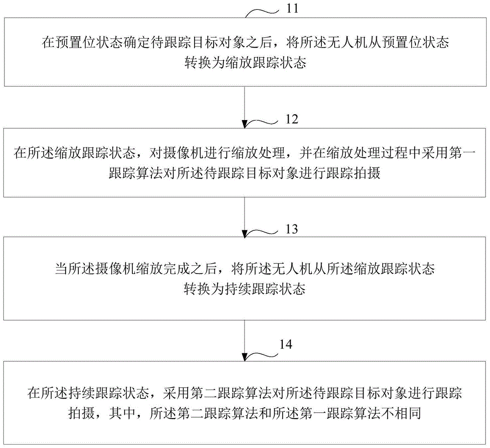
Fig. 1 is a schematic flowchart of a method for tracking shooting according to an embodiment of the present disclosure. The method is applied to the unmanned aerial vehicle, and can be as follows.
Step 11: and after the target object to be tracked is determined in the preset state, the unmanned aerial vehicle is converted into a zooming tracking state from the preset state.
Wherein the preset bit state represents an initial state of the drone.
In step 11, after the drone determines the target object to be tracked in the preset bit state, the state of the drone is switched from the preset bit state to the zoom tracking state.
In an alternative embodiment of the present application, the method further comprises:
and in the preset bit state, determining the target object to be tracked.
Specifically, the first step: and detecting and marking a trackable target object set in the video frame sequence shot in the preset position state by adopting a preset detection algorithm.
Wherein, the trackable target object set comprises the target object to be tracked.
And for the video frame sequence shot by the unmanned aerial vehicle in the preset state, detecting a plurality of moving targets in the video frame sequence shot by the unmanned aerial vehicle in the preset state by adopting a preset detection algorithm, determining the moving targets as a plurality of trackable target objects to obtain the trackable target object set, and marking a target frame containing the trackable target objects in any video frame of the video frame sequence shot by the unmanned aerial vehicle in the preset state.
It should be noted that the preset detection algorithm may be a background modeling algorithm, a motion analysis algorithm, a detector detection algorithm, or other algorithms capable of achieving moving object detection, and is not specifically limited herein.
After detecting the set of trackable target objects, the method further comprises:
setting corresponding identification codes for all trackable target objects in the trackable target object set;
in the preset position state, tracking shooting each trackable target object by adopting a third tracking algorithm;
setting corresponding identification codes for the respective trackable target objects in the set of trackable target objects so that the respective trackable target objects are distinguished from each other.
In the preset position state, the third tracking algorithm is adopted to track and shoot each trackable target object, that is, the third tracking algorithm is adopted to detect each trackable target object in the video frames shot by the camera in the preset position state, so as to obtain a video frame sequence marked with a target frame containing each trackable target object, and therefore, according to the video frame sequence marked with the target frame containing each trackable target object, the motion track information of each trackable target object can be obtained.
It should be noted that the third tracking algorithm is a multi-target tracking algorithm.
The second step is that: and sending the video frame sequence marked with the trackable target object set to a terminal device.
The terminal equipment is used for displaying a video frame sequence obtained by shooting of the camera.
The unmanned aerial vehicle sends the video frame sequence marked with the trackable target object set to the terminal equipment which is in communication connection with the unmanned aerial vehicle on the ground, so that a user can check each trackable target object and the motion state of each trackable target object in the video frame sequence marked with the trackable target object set through the terminal equipment.
It should be noted that the terminal device may be a smart phone, a tablet computer, a personal computer, or other terminal devices, which is not limited herein.
Fig. 2 is a video frame marked with a trackable target object according to an embodiment of the present application.
As shown in fig. 2, the trackable target objects marked in the video frame include four objects: the identification code of the first trackable target object is 001, the identification code of the second trackable target object is 002, the identification code of the third trackable target object is 003, and the identification code of the fourth trackable target object is 004.
The third step: and determining the coordinates of the tracking point returned from the terminal equipment.
Wherein the tracking point coordinates represent coordinates of the target object to be tracked in a certain video frame in the video frame sequence.
And the user checks each trackable target object in the video frame sequence marked with the trackable target object set through the terminal equipment, clicks and selects the target object to be tracked in a certain video frame currently displayed by the terminal equipment, the unmanned aerial vehicle determines the position clicked by the user as a tracking point, and determines the coordinate of the tracking point in the video frame clicked and selected by the user to the target object to be tracked.
The fourth step: and determining the target object to be tracked in the preset position state according to the tracking point coordinates.
The video frame sequence marked with the trackable target object set and shot by the unmanned aerial vehicle is transmitted to the terminal equipment on the ground with a certain time delay, so that the video frame of the target object to be tracked, which is clicked and selected by a user, is different from the current video frame shot by the unmanned aerial vehicle, and at the moment, the target object to be tracked can be accurately determined in the preset position state according to the tracking point coordinate.
Specifically, firstly, the identification code of the target object to be tracked is determined according to the tracking point coordinates and the video frame sequence obtained by tracking and shooting each trackable target object by the third tracking method in the preset position state.
Matching the coordinates of the tracking point with the motion trail information of each trackable target object in the video frame sequence marked with the trackable target object set acquired in the preset state, finding the trackable target object matched with the coordinates of the tracking point from the motion trail information through a related matching algorithm, determining the trackable target object as the target object to be tracked, and further determining the identification code of the target object to be tracked.
And then, determining the target object to be tracked in the preset position state according to the identification code of the target object to be tracked.
And in the preset state, determining a trackable target object corresponding to the identification code, and further determining the trackable target object as the trackable target object.
And matching the coordinates of the tracking points with the motion trail information of each trackable target object, determining the identification code of the target object to be tracked, and further determining the target object to be tracked in the preset state, so that the problem of inaccurate matching of the target object to be tracked caused by video frame transmission delay can be avoided.
After the target object to be tracked is determined in the preset bit state, for any video frame of a video frame sequence tracked and shot by the camera, a target frame containing the target object to be tracked can be tracked and detected by adopting a related tracking algorithm, so that the motion trail information of the target object to be tracked can be checked according to the video frame sequence.
Step 12: and in the zooming and tracking state, zooming the camera, and adopting a first tracking algorithm to track and shoot the target object to be tracked in the zooming and tracking process.
Wherein the camera is located in the drone.
In step 12, after the unmanned aerial vehicle is converted from the preset state to the zoom tracking state, zooming the camera, and adjusting an image state of the target object to be tracked in the camera, so that the target object to be tracked can be better tracked and shot, and tracking and shooting the target object to be tracked by using a first tracking algorithm in the zooming process, that is, tracking and detecting the target object to be tracked in a video frame obtained by shooting with the camera by using the first tracking algorithm, so as to obtain a video frame sequence marked with a target frame including the target object to be tracked.
In the zooming and tracking state, operations such as focal length zooming, position translation and the like need to be performed on the camera, so that the target object to be tracked keeps a proper image size and an image position in the camera, and the target object to be tracked can be better tracked and shot.
Specifically, first, the camera is translated so that the image position of the target object to be tracked in the camera reaches a preset position.
The method comprises the steps of adjusting an airborne cloud deck for placing a camera, translating the camera, and adjusting the image position of a target object to be tracked in the camera, so that the position of the target object to be tracked in the camera reaches a preset position.
It should be noted that the preset position may be determined according to actual situations, and is not specifically limited herein.
And then, adjusting the focal length of the camera to a preset focal length, so that the size of the image of the target object to be tracked in the camera reaches a preset size.
And amplifying or reducing the size of the target object to be tracked in the camera by adjusting the focal length of the camera, wherein when the focal length of the camera is adjusted to the preset focal length, the size of the image of the target object to be tracked in the camera reaches the preset size.
It should be noted that the preset size may be determined according to actual situations, and is not specifically limited herein.
In the process of zooming the camera, the target object to be tracked can have a large change in the image position and the image size in the camera along with operations such as translation, focal length adjustment and the like of the camera, so that the target object to be tracked has a problem of image blurring in a video frame obtained by shooting with the camera.
In order to accurately track and detect the target object to be tracked in the state of image blurring, in the zooming process, a first tracking algorithm is adopted to track and shoot the target object to be tracked, that is, the first tracking algorithm is adopted to track and detect the target object to be tracked in a video frame shot in the zooming process of the camera, so as to obtain a video frame sequence marked with a target frame of the target object to be tracked.
Preferably, the first tracking algorithm is a single-point optical flow tracking algorithm.
It should be noted that the first tracking algorithm may be other tracking algorithms besides the single-point optical flow tracking algorithm, and is not limited in this respect.
Step 13: after the camera zoom is complete, transitioning the drone from the zoom tracking state to a continuous tracking state.
In step 13, after zooming of the camera is completed, so that the image position of the target object to be tracked in the camera is at a preset position and the image size is at a preset size, the unmanned aerial vehicle is switched from the zooming tracking state to the continuous tracking state, so that continuous tracking shooting can be performed on the target object to be tracked.
Step 14: and in the continuous tracking state, tracking and shooting the target object to be tracked by adopting a second tracking algorithm.
Wherein the second tracking algorithm is different from the first tracking algorithm.
In step 14, after the unmanned aerial vehicle is converted from the zoom tracking state to the continuous tracking state, a second tracking algorithm is used to perform continuous tracking shooting on the target object to be tracked, that is, the target object to be tracked in the video frame shot by the camera is tracked and detected by using the second tracking algorithm, so as to obtain a video frame sequence marked with a target frame including the target object to be tracked.
And storing the video frame sequence marked with the target frame containing the target object to be tracked in the unmanned aerial vehicle, which is obtained in the continuous tracking state, and transmitting the video frame sequence marked with the target frame containing the target object to be tracked to the terminal equipment on the ground, so that a user can play the video frame sequence according to the terminal equipment and check the motion trail information of the target object to be tracked.
Preferably, the second tracking algorithm is a particle filter tracking algorithm.
It should be noted that the second tracking algorithm may be a particle filter tracking algorithm, and may also be other tracking algorithms capable of performing continuous tracking shooting on the target object to be tracked, which is not specifically limited herein.
In the continuous tracking state, tracking shooting is carried out on the target object to be tracked by adopting a tracking algorithm different from the zooming tracking state, so that the accuracy of the tracking shooting process can be ensured, and the robustness of tracking shooting is ensured.
In an alternative embodiment of the present application, the method further comprises:
judging whether the target object to be tracked is lost in the continuous tracking state;
when the target object to be tracked is determined to be lost, the target object to be tracked is searched again in the continuous tracking state.
When judging whether the continuous tracking state loses the target object to be tracked, specifically:
firstly, a video frame sequence obtained by tracking and shooting the target object to be tracked by adopting the second tracking algorithm in the continuous tracking state is obtained.
Then, when the target object to be tracked is not contained in the video frames which are continuous and exceed the preset frame number in the video frame sequence, it is determined that the target object to be tracked is lost in the continuous tracking state.
By acquiring a video frame sequence obtained by tracking and shooting the target object to be tracked by adopting the second tracking algorithm in the continuous tracking state, when the target object to be tracked is not contained in the video frames which are continuous and exceed the preset frame number in the video frame sequence, namely when the target object to be tracked cannot be detected by the second tracking algorithm in the video frames which are continuous and exceed the preset frame number, the unmanned aerial vehicle can be determined to lose the target object to be tracked in the continuous tracking state.
For example: and when the target object to be tracked cannot be detected in the continuous 50 frames of video frames of the video frame sequence by the second tracking algorithm, determining that the unmanned aerial vehicle loses the target object to be tracked in the continuous tracking state.
When it is determined that the target object to be tracked has been lost, re-searching the target object to be tracked in the continuous tracking state, specifically:
firstly, in the continuous tracking state, extracting first characteristic information of the target object to be tracked from a video frame sequence obtained by tracking and shooting the target object to be tracked by adopting the second tracking algorithm.
Secondly, extracting second characteristic information of a motion area in a video frame sequence shot after the continuous tracking state is determined to lose the target object to be tracked.
In a video frame sequence obtained by shooting after the continuous tracking state is determined to have lost the target object to be tracked, a motion area in the video frame sequence is searched, and second characteristic information of the motion area is extracted.
Then, the similarity of the first feature information and the second feature information is compared.
And finally, judging whether the target object to be tracked is found in the continuous tracking state or not according to the comparison result.
When the similarity of the first characteristic information and the second characteristic information is larger than a preset value, determining that the target object to be tracked is found again in the continuous tracking state;
when the similarity of the first characteristic information and the second characteristic information is not larger than the preset value, the target object to be tracked is searched again in the continuous tracking state;
and when the duration of re-searching the target object to be tracked in the continuous tracking state is longer than the preset duration, determining that the target object to be tracked is not re-searched in the continuous tracking state.
It should be noted that the preset value may be determined according to actual situations, and is not specifically limited herein.
It should be noted that the preset time period may be determined according to actual situations, and is not specifically limited herein.
In an optional embodiment of the present application, when the number of times of searching for the target object to be tracked again in the continuous tracking state is greater than a preset number of times, it is determined that the target object to be tracked is not found again in the continuous tracking state.
It should be noted that the preset number of times may be determined according to actual situations, and is not specifically limited herein.
In an optional embodiment of the present application, after determining that the target object to be tracked is found again in the continuous tracking state, tracking shooting is performed on the target object to be tracked by using the second tracking algorithm.
In an optional embodiment of the present application, after it is determined that the target object to be tracked is not found again in the continuous tracking state, the drone is switched from the continuous tracking state to the preset bit state.
After the unmanned aerial vehicle determines that the target object to be tracked is not found again in the continuous tracking state, the unmanned aerial vehicle can be switched to the preset bit state from the continuous tracking state by restarting the unmanned aerial vehicle, so that the camera returns to the predefined shooting angle and the predefined focal length again, and then the tracking shooting of the target object to be tracked is performed again.
It should be noted that, by restarting the unmanned aerial vehicle, after the unmanned aerial vehicle is converted from the continuous tracking state to the preset state, the shooting angle and the focal length of the camera may be reset according to actual needs, which is not specifically limited herein.
In an optional embodiment of the present application, after the unmanned aerial vehicle determines that the target object to be tracked has been lost in the continuous tracking state, the unmanned aerial vehicle may enter a hovering state, wait for a user to resend an instruction through the terminal device on the ground, and then perform corresponding operations according to the instruction.
In an optional embodiment of the present application, it may also be avoided that the target object to be tracked is lost in the continuous tracking state by a detector, specifically, first, for any video frame in a sequence of video frames captured in the continuous tracking state, the target object to be tracked is detected by the detector, and the target object to be tracked detected by the detector is compared with the target object to be tracked detected by tracking the video frame by the second tracking algorithm.
Secondly, when the detection result is matched with the tracking result, namely the target object to be tracked detected by the detector is matched with the target object to be tracked detected by the second tracking algorithm, the unmanned aerial vehicle is determined not to lose the target object to be tracked in the video frame.
When the detection result is not matched with the tracking result, namely the target object to be tracked detected by the detector is not matched with the target object to be tracked detected by the second tracking algorithm, and when a difference exists, the image of the target object to be tracked in the camera is adjusted by adjusting the state of the camera, so that the situation that the target object to be tracked is lost in the continuous tracking state is avoided.
The video frame sequence shot in the continuous tracking state is detected by the detector, so that the situation that the target object to be tracked is lost in the continuous tracking state can be avoided, and the robustness of tracking shooting is ensured.
Meanwhile, the embodiment of the application also provides the unmanned aerial vehicle, and the unmanned aerial vehicle adopts the tracking shooting method to perform tracking shooting on the target object to be tracked.
Example 2
Based on the same inventive concept, fig. 3 is a schematic diagram of a workflow of the unmanned aerial vehicle in a preset state according to the embodiment of the present application.
As shown in fig. 3, the unmanned aerial vehicle is in a preset state, the unmanned aerial vehicle performs target detection on a video frame sequence obtained by shooting the unmanned aerial vehicle in the preset state by using a preset detection algorithm, detects a set of trackable target objects in the video frame sequence, and sends the video frame sequence marked with each trackable target object in the set of trackable target objects to a terminal device.
And after the unmanned aerial vehicle determines the trackable target object set, tracking and shooting each trackable target object by adopting a multi-target tracking algorithm.
The method comprises the steps that a user views each trackable target object in a video frame sequence marked with each trackable target object in a trackable target object set through the terminal equipment, the target object to be tracked is clicked and selected in a certain video frame currently displayed by the terminal equipment, the unmanned aerial vehicle determines the position clicked by the user as a tracking point, and the coordinate of the tracking point in the video frame where the user clicks and selects the target object to be tracked is determined.
Matching the tracking point coordinates with motion trail information of each trackable target object in a video frame sequence obtained by tracking and shooting each trackable target object by adopting a multi-target tracking algorithm, and further determining the target object to be tracked in the preset position state.
Example 3
Based on the same inventive concept, fig. 4 is a schematic view of a workflow of the unmanned aerial vehicle in a tracking shooting state provided by the embodiment of the present application.
As shown in fig. 4, when the unmanned aerial vehicle is in a zoom tracking state, zooming is performed on a camera in the unmanned aerial vehicle, and a first tracking algorithm is adopted to perform tracking shooting on a target object to be tracked in the zooming process.
As shown in fig. 4, when the unmanned aerial vehicle is in a continuous tracking state, a second tracking algorithm is adopted to perform tracking shooting on the target object to be tracked.
And detecting the target object to be tracked by adopting a detector for the video frame sequence shot in the continuous tracking state, comparing the detection result obtained by the detector with the tracking result obtained by the second tracking algorithm, judging whether the target object to be tracked is lost in the continuous tracking state, and searching the target object to be tracked again in the continuous tracking state when the target object to be tracked is determined to be lost.
Example 4
Based on the same inventive concept, fig. 5 is a schematic diagram of a workflow for re-finding a target object to be tracked in a continuous tracking state according to an embodiment of the present application.
As shown in fig. 5, when it is determined that the target object to be tracked has been lost in the continuous tracking state, extracting first feature information of the target object to be tracked from a video frame sequence obtained by performing tracking shooting on the target object to be tracked by using the second tracking algorithm in the continuous tracking state.
And performing image rectification on the video frame sequence shot after the continuous tracking state is determined to lose the target object to be tracked, searching a motion area in the video frame sequence, and extracting second characteristic information of the motion area.
And comparing the similarity of the first characteristic information and the second characteristic information.
When the similarity of the first characteristic information and the second characteristic information is larger than a preset value, determining that the target object to be tracked is found again in the continuous tracking state;
when the similarity of the first characteristic information and the second characteristic information is not larger than the preset value, skipping to execute the operation of searching the target object to be tracked again in the continuous tracking state;
and when the duration of re-searching the target object to be tracked in the continuous tracking state is longer than the preset duration, determining that the target object to be tracked is not re-searched in the continuous tracking state.
Example 5
Fig. 6 is a schematic structural diagram of a device for tracking shooting according to an embodiment of the present application. The apparatus 60 comprises: a conversion module 601, a first tracking module 602, and a second tracking module 603, wherein:
the conversion module 601 is configured to convert the unmanned aerial vehicle from a preset state to a zooming tracking state after the target object to be tracked is determined in the preset state, where the preset state represents an initial state of the unmanned aerial vehicle;
a first tracking module 602, configured to, in the zoom tracking state, perform zoom processing on a camera, and perform tracking shooting on the target object to be tracked by using a first tracking algorithm in the zoom processing process, where the camera is located in the unmanned aerial vehicle;
the conversion module 601 is further configured to convert the drone from the zoom tracking state to the continuous tracking state after the camera zoom is completed;
and a second tracking module 603, configured to perform tracking shooting on the target to be tracked by using a second tracking algorithm in the continuous tracking state, where the second tracking algorithm is different from the first tracking algorithm.
It should be noted that the first tracking algorithm may be other tracking algorithms besides the single-point optical flow tracking algorithm, and is not limited in this respect.
It should be noted that the second tracking algorithm may be a particle filter tracking algorithm, and may also be other tracking algorithms capable of performing continuous tracking shooting on the target object to be tracked, which is not specifically limited herein.
Preferably, the apparatus 60 further comprises: a scaling module, wherein:
the zooming module is used for translating the camera to enable the image position of the target object to be tracked in the camera to reach a preset position;
the zooming module is further configured to adjust the focal length of the camera to a preset focal length, so that the size of the image of the target object to be tracked in the camera reaches a preset size.
It should be noted that the preset position may be determined according to actual situations, and is not specifically limited herein.
It should be noted that the preset size may be determined according to actual situations, and is not specifically limited herein.
Preferably, the apparatus 60 further comprises: a decision block and re-seek block 608, wherein:
the judging module is used for judging whether the target object to be tracked is lost in the continuous tracking state;
and the re-searching module is used for re-searching the target object to be tracked in the continuous tracking state when the target object to be tracked is determined to be lost.
Preferably, the determining module determines whether the target object to be tracked is lost in the continuous tracking state, including:
acquiring a video frame sequence obtained by tracking and shooting the target object to be tracked by adopting the second tracking algorithm in the continuous tracking state;
when the continuous video frames which exceed the preset frame number in the video frame sequence do not contain the target object to be tracked, determining that the target object to be tracked is lost in the continuous tracking state.
Preferably, the re-finding module re-finds the target object to be tracked in the continuous tracking state, including:
extracting first characteristic information of the target object to be tracked from a video frame sequence obtained by tracking and shooting the target object to be tracked by adopting the second tracking algorithm in the continuous tracking state;
extracting second characteristic information of a motion area from a video frame sequence shot after the continuous tracking state is determined to lose the target object to be tracked;
comparing the similarity of the first characteristic information and the second characteristic information;
and judging whether the target object to be tracked is found in the continuous tracking state or not according to the comparison result.
Preferably, the re-finding module determines whether to re-find the target object to be tracked in the continuous tracking state according to the comparison result, including:
when the similarity of the first characteristic information and the second characteristic information is larger than a preset value, determining that the target object to be tracked is found again in the continuous tracking state;
when the similarity of the first characteristic information and the second characteristic information is not larger than the preset value, the target object to be tracked is searched again in the continuous tracking state;
and when the duration of re-searching the target object to be tracked in the continuous tracking state is longer than the preset duration, determining that the target object to be tracked is not re-searched in the continuous tracking state.
It should be noted that the preset value may be determined according to actual situations, and is not specifically limited herein.
It should be noted that the preset time period may be determined according to actual situations, and is not specifically limited herein.
Preferably, the second tracking module 603 is further configured to perform tracking shooting on the target object to be tracked by using the second tracking algorithm after determining that the target object to be tracked is found again in the continuous tracking state.
Preferably, the conversion module 601 is further configured to convert the drone from the continuous tracking state to the preset bit state after determining that the target object to be tracked is not found again in the continuous tracking state.
Preferably, the apparatus 60 further comprises: a determination module, wherein:
the determining module is configured to determine the target object to be tracked in the preset bit state.
Preferably, the apparatus 60 further comprises: detection module and sending module, wherein:
the detection module is used for detecting and marking a trackable target object set in a video frame sequence obtained by shooting in the preset position state by adopting a preset detection algorithm, wherein the trackable target object set comprises the target object to be tracked;
the sending module is configured to send a video frame sequence marked with the trackable target object set obtained in the preset state to a terminal device, where the terminal device is configured to display the video frame sequence obtained by shooting with the camera;
the determining module is further configured to determine a tracking point coordinate returned by the terminal device, where the tracking point coordinate represents a coordinate of the target object to be tracked in a certain video frame of the sequence of video frames;
the determining module is further configured to determine the target object to be tracked in the preset position state according to the tracking point coordinates.
It should be noted that the preset detection algorithm may be a background modeling algorithm, a motion analysis algorithm, a detector detection algorithm, or other algorithms capable of achieving moving object detection, and is not specifically limited herein.
It should be noted that the terminal device may be a smart phone, a tablet computer, a personal computer, or other terminal devices, which is not limited herein.
Preferably, the apparatus 60 further comprises: a setup module and a third tracking module, wherein:
the setting module is used for setting corresponding identification codes for all trackable target objects in the trackable target object set;
the third tracking module is used for tracking and shooting each trackable target object by adopting a third tracking algorithm in the preset position state;
the determining module is further configured to determine an identification code of the target object to be tracked according to the tracking point coordinates and a video frame sequence obtained by tracking and shooting each trackable target object in the preset bit state by using the third tracking method;
the determining module is further configured to determine the target object to be tracked in the preset bit state according to the identification code of the target object to be tracked.
It should be noted that the third tracking algorithm is a multi-target tracking algorithm.
Through the tracking shooting device, a conversion module is used for converting the unmanned aerial vehicle from a preset state to a zooming tracking state after a target object to be tracked is determined in the preset state, wherein the preset state represents an initial state of the unmanned aerial vehicle; the first tracking module is used for zooming the camera in the zooming and tracking state and tracking and shooting the target object to be tracked by adopting a first tracking algorithm in the zooming and tracking process, wherein the camera is positioned in the unmanned aerial vehicle; the conversion module is further configured to convert the unmanned aerial vehicle from the zoom tracking state to a continuous tracking state after zooming of the camera is completed; the second tracking module is used for tracking and shooting the target object to be tracked by adopting a second tracking algorithm in the continuous tracking state, wherein the second tracking algorithm is different from the first tracking algorithm, so that the target object to be tracked can be tracked and shot by adopting different tracking algorithms in the zooming tracking state and the continuous tracking state, the tracking and shooting accuracy is ensured, and the tracking and shooting robustness is effectively improved.
As will be appreciated by one skilled in the art, embodiments of the present application may be provided as a method, system, or computer program product. Accordingly, the present application may take the form of an entirely hardware embodiment, an entirely software embodiment or an embodiment combining software and hardware aspects. Furthermore, the present application may take the form of a computer program product embodied on one or more computer-usable storage media (including, but not limited to, disk storage, CD-ROM, optical storage, and the like) having computer-usable program code embodied therein.
The present application is described with reference to flowchart illustrations and/or block diagrams of methods, apparatus (systems), and computer program products according to embodiments of the application. It will be understood that each flow and/or block of the flow diagrams and/or block diagrams, and combinations of flows and/or blocks in the flow diagrams and/or block diagrams, can be implemented by computer program instructions. These computer program instructions may be provided to a processor of a general purpose computer, special purpose computer, embedded processor, or other programmable data processing apparatus to produce a machine, such that the instructions, which execute via the processor of the computer or other programmable data processing apparatus, create means for implementing the functions specified in the flowchart flow or flows and/or block diagram block or blocks.
These computer program instructions may also be stored in a computer-readable memory that can direct a computer or other programmable data processing apparatus to function in a particular manner, such that the instructions stored in the computer-readable memory produce an article of manufacture including instruction means which implement the function specified in the flowchart flow or flows and/or block diagram block or blocks.
These computer program instructions may also be loaded onto a computer or other programmable data processing apparatus to cause a series of operational steps to be performed on the computer or other programmable apparatus to produce a computer implemented process such that the instructions which execute on the computer or other programmable apparatus provide steps for implementing the functions specified in the flowchart flow or flows and/or block diagram block or blocks.
In a typical configuration, a computing device includes one or more processors (CPUs), input/output interfaces, network interfaces, and memory.
The memory may include forms of volatile memory in a computer readable medium, Random Access Memory (RAM) and/or non-volatile memory, such as Read Only Memory (ROM) or flash memory (flash RAM). Memory is an example of a computer-readable medium.
Computer-readable media, including both non-transitory and non-transitory, removable and non-removable media, may implement information storage by any method or technology. The information may be computer readable instructions, data structures, modules of a program, or other data. Examples of computer storage media include, but are not limited to, phase change memory (PRAM), Static Random Access Memory (SRAM), Dynamic Random Access Memory (DRAM), other types of Random Access Memory (RAM), Read Only Memory (ROM), Electrically Erasable Programmable Read Only Memory (EEPROM), flash memory or other memory technology, compact disc read only memory (CD-ROM), Digital Versatile Discs (DVD) or other optical storage, magnetic cassettes, magnetic tape magnetic disk storage or other magnetic storage devices, or any other non-transmission medium that can be used to store information that can be accessed by a computing device. As defined herein, a computer readable medium does not include a transitory computer readable medium such as a modulated data signal and a carrier wave.
It should also be noted that the terms "comprises," "comprising," or any other variation thereof, are intended to cover a non-exclusive inclusion, such that a process, method, article, or apparatus that comprises a list of elements does not include only those elements but may include other elements not expressly listed or inherent to such process, method, article, or apparatus. Without further limitation, an element defined by the phrase "comprising an … …" does not exclude the presence of other like elements in a process, method, article, or apparatus that comprises the element.
As will be appreciated by one skilled in the art, embodiments of the present application may be provided as a method, system, or computer program product. Accordingly, the present application may take the form of an entirely hardware embodiment, an entirely software embodiment or an embodiment combining software and hardware aspects. Furthermore, the present application may take the form of a computer program product embodied on one or more computer-usable storage media (including, but not limited to, disk storage, CD-ROM, optical storage, and the like) having computer-usable program code embodied therein.
The above description is only an example of the present application and is not intended to limit the present application. Various modifications and changes may occur to those skilled in the art. Any modification, equivalent replacement, improvement, etc. made within the spirit and principle of the present application should be included in the scope of the claims of the present application.