CN108474397B - Connector with a locking member - Google Patents
Connector with a locking member Download PDFInfo
- Publication number
- CN108474397B CN108474397B CN201680062004.XA CN201680062004A CN108474397B CN 108474397 B CN108474397 B CN 108474397B CN 201680062004 A CN201680062004 A CN 201680062004A CN 108474397 B CN108474397 B CN 108474397B
- Authority
- CN
- China
- Prior art keywords
- connector
- connector according
- cage
- locking element
- locking elements
- Prior art date
- Legal status (The legal status is an assumption and is not a legal conclusion. Google has not performed a legal analysis and makes no representation as to the accuracy of the status listed.)
- Active
Links
- 230000000717 retained effect Effects 0.000 claims abstract description 10
- 238000000034 method Methods 0.000 claims description 23
- 239000003351 stiffener Substances 0.000 claims description 14
- 230000007704 transition Effects 0.000 claims description 6
- 238000005452 bending Methods 0.000 claims description 4
- 230000001419 dependent effect Effects 0.000 claims 1
- 238000003780 insertion Methods 0.000 description 4
- 230000000007 visual effect Effects 0.000 description 4
- 238000012423 maintenance Methods 0.000 description 3
- 238000012986 modification Methods 0.000 description 3
- 230000004048 modification Effects 0.000 description 3
- IJGRMHOSHXDMSA-UHFFFAOYSA-N Atomic nitrogen Chemical compound N#N IJGRMHOSHXDMSA-UHFFFAOYSA-N 0.000 description 2
- 230000006835 compression Effects 0.000 description 2
- 238000007906 compression Methods 0.000 description 2
- 230000007423 decrease Effects 0.000 description 2
- 230000037431 insertion Effects 0.000 description 2
- 238000005096 rolling process Methods 0.000 description 2
- 208000033999 Device damage Diseases 0.000 description 1
- 210000000988 bone and bone Anatomy 0.000 description 1
- 230000001066 destructive effect Effects 0.000 description 1
- 239000007789 gas Substances 0.000 description 1
- 229910052757 nitrogen Inorganic materials 0.000 description 1
Images


Classifications
-
- F—MECHANICAL ENGINEERING; LIGHTING; HEATING; WEAPONS; BLASTING
- F16—ENGINEERING ELEMENTS AND UNITS; GENERAL MEASURES FOR PRODUCING AND MAINTAINING EFFECTIVE FUNCTIONING OF MACHINES OR INSTALLATIONS; THERMAL INSULATION IN GENERAL
- F16L—PIPES; JOINTS OR FITTINGS FOR PIPES; SUPPORTS FOR PIPES, CABLES OR PROTECTIVE TUBING; MEANS FOR THERMAL INSULATION IN GENERAL
- F16L5/00—Devices for use where pipes, cables or protective tubing pass through walls or partitions
-
- F—MECHANICAL ENGINEERING; LIGHTING; HEATING; WEAPONS; BLASTING
- F16—ENGINEERING ELEMENTS AND UNITS; GENERAL MEASURES FOR PRODUCING AND MAINTAINING EFFECTIVE FUNCTIONING OF MACHINES OR INSTALLATIONS; THERMAL INSULATION IN GENERAL
- F16B—DEVICES FOR FASTENING OR SECURING CONSTRUCTIONAL ELEMENTS OR MACHINE PARTS TOGETHER, e.g. NAILS, BOLTS, CIRCLIPS, CLAMPS, CLIPS OR WEDGES; JOINTS OR JOINTING
- F16B7/00—Connections of rods or tubes, e.g. of non-circular section, mutually, including resilient connections
- F16B7/04—Clamping or clipping connections
- F16B7/0406—Clamping or clipping connections for rods or tubes being coaxial
- F16B7/0413—Clamping or clipping connections for rods or tubes being coaxial for tubes using the innerside thereof
- F16B7/042—Clamping or clipping connections for rods or tubes being coaxial for tubes using the innerside thereof with a locking element, e.g. pin, ball or pushbutton, engaging in a hole in the wall of at least one tube
-
- F—MECHANICAL ENGINEERING; LIGHTING; HEATING; WEAPONS; BLASTING
- F03—MACHINES OR ENGINES FOR LIQUIDS; WIND, SPRING, OR WEIGHT MOTORS; PRODUCING MECHANICAL POWER OR A REACTIVE PROPULSIVE THRUST, NOT OTHERWISE PROVIDED FOR
- F03D—WIND MOTORS
- F03D1/00—Wind motors with rotation axis substantially parallel to the air flow entering the rotor
-
- F—MECHANICAL ENGINEERING; LIGHTING; HEATING; WEAPONS; BLASTING
- F03—MACHINES OR ENGINES FOR LIQUIDS; WIND, SPRING, OR WEIGHT MOTORS; PRODUCING MECHANICAL POWER OR A REACTIVE PROPULSIVE THRUST, NOT OTHERWISE PROVIDED FOR
- F03D—WIND MOTORS
- F03D80/00—Details, components or accessories not provided for in groups F03D1/00 - F03D17/00
-
- F—MECHANICAL ENGINEERING; LIGHTING; HEATING; WEAPONS; BLASTING
- F16—ENGINEERING ELEMENTS AND UNITS; GENERAL MEASURES FOR PRODUCING AND MAINTAINING EFFECTIVE FUNCTIONING OF MACHINES OR INSTALLATIONS; THERMAL INSULATION IN GENERAL
- F16B—DEVICES FOR FASTENING OR SECURING CONSTRUCTIONAL ELEMENTS OR MACHINE PARTS TOGETHER, e.g. NAILS, BOLTS, CIRCLIPS, CLAMPS, CLIPS OR WEDGES; JOINTS OR JOINTING
- F16B7/00—Connections of rods or tubes, e.g. of non-circular section, mutually, including resilient connections
- F16B7/10—Telescoping systems
- F16B7/14—Telescoping systems locking in intermediate non-discrete positions
- F16B7/1409—Telescoping systems locking in intermediate non-discrete positions with balls or rollers urged by an axial displacement of a wedge or a conical member
-
- F—MECHANICAL ENGINEERING; LIGHTING; HEATING; WEAPONS; BLASTING
- F16—ENGINEERING ELEMENTS AND UNITS; GENERAL MEASURES FOR PRODUCING AND MAINTAINING EFFECTIVE FUNCTIONING OF MACHINES OR INSTALLATIONS; THERMAL INSULATION IN GENERAL
- F16L—PIPES; JOINTS OR FITTINGS FOR PIPES; SUPPORTS FOR PIPES, CABLES OR PROTECTIVE TUBING; MEANS FOR THERMAL INSULATION IN GENERAL
- F16L1/00—Laying or reclaiming pipes; Repairing or joining pipes on or under water
- F16L1/12—Laying or reclaiming pipes on or under water
- F16L1/123—Devices for the protection of pipes under water
-
- F—MECHANICAL ENGINEERING; LIGHTING; HEATING; WEAPONS; BLASTING
- F16—ENGINEERING ELEMENTS AND UNITS; GENERAL MEASURES FOR PRODUCING AND MAINTAINING EFFECTIVE FUNCTIONING OF MACHINES OR INSTALLATIONS; THERMAL INSULATION IN GENERAL
- F16L—PIPES; JOINTS OR FITTINGS FOR PIPES; SUPPORTS FOR PIPES, CABLES OR PROTECTIVE TUBING; MEANS FOR THERMAL INSULATION IN GENERAL
- F16L1/00—Laying or reclaiming pipes; Repairing or joining pipes on or under water
- F16L1/12—Laying or reclaiming pipes on or under water
- F16L1/20—Accessories therefor, e.g. floats, weights
-
- F—MECHANICAL ENGINEERING; LIGHTING; HEATING; WEAPONS; BLASTING
- F16—ENGINEERING ELEMENTS AND UNITS; GENERAL MEASURES FOR PRODUCING AND MAINTAINING EFFECTIVE FUNCTIONING OF MACHINES OR INSTALLATIONS; THERMAL INSULATION IN GENERAL
- F16L—PIPES; JOINTS OR FITTINGS FOR PIPES; SUPPORTS FOR PIPES, CABLES OR PROTECTIVE TUBING; MEANS FOR THERMAL INSULATION IN GENERAL
- F16L37/00—Couplings of the quick-acting type
- F16L37/22—Couplings of the quick-acting type in which the connection is maintained by means of balls, rollers or helical springs under radial pressure between the parts
- F16L37/23—Couplings of the quick-acting type in which the connection is maintained by means of balls, rollers or helical springs under radial pressure between the parts by means of balls
-
- H—ELECTRICITY
- H02—GENERATION; CONVERSION OR DISTRIBUTION OF ELECTRIC POWER
- H02G—INSTALLATION OF ELECTRIC CABLES OR LINES, OR OF COMBINED OPTICAL AND ELECTRIC CABLES OR LINES
- H02G1/00—Methods or apparatus specially adapted for installing, maintaining, repairing or dismantling electric cables or lines
- H02G1/06—Methods or apparatus specially adapted for installing, maintaining, repairing or dismantling electric cables or lines for laying cables, e.g. laying apparatus on vehicle
- H02G1/10—Methods or apparatus specially adapted for installing, maintaining, repairing or dismantling electric cables or lines for laying cables, e.g. laying apparatus on vehicle in or under water
-
- H—ELECTRICITY
- H02—GENERATION; CONVERSION OR DISTRIBUTION OF ELECTRIC POWER
- H02G—INSTALLATION OF ELECTRIC CABLES OR LINES, OR OF COMBINED OPTICAL AND ELECTRIC CABLES OR LINES
- H02G9/00—Installations of electric cables or lines in or on the ground or water
- H02G9/02—Installations of electric cables or lines in or on the ground or water laid directly in or on the ground, river-bed or sea-bottom; Coverings therefor, e.g. tile
- H02G9/025—Coverings therefor, e.g. tile
-
- H—ELECTRICITY
- H02—GENERATION; CONVERSION OR DISTRIBUTION OF ELECTRIC POWER
- H02G—INSTALLATION OF ELECTRIC CABLES OR LINES, OR OF COMBINED OPTICAL AND ELECTRIC CABLES OR LINES
- H02G9/00—Installations of electric cables or lines in or on the ground or water
- H02G9/12—Installations of electric cables or lines in or on the ground or water supported on or from floats, e.g. in water
-
- F—MECHANICAL ENGINEERING; LIGHTING; HEATING; WEAPONS; BLASTING
- F16—ENGINEERING ELEMENTS AND UNITS; GENERAL MEASURES FOR PRODUCING AND MAINTAINING EFFECTIVE FUNCTIONING OF MACHINES OR INSTALLATIONS; THERMAL INSULATION IN GENERAL
- F16B—DEVICES FOR FASTENING OR SECURING CONSTRUCTIONAL ELEMENTS OR MACHINE PARTS TOGETHER, e.g. NAILS, BOLTS, CIRCLIPS, CLAMPS, CLIPS OR WEDGES; JOINTS OR JOINTING
- F16B2/00—Friction-grip releasable fastenings
- F16B2/02—Clamps, i.e. with gripping action effected by positive means other than the inherent resistance to deformation of the material of the fastening
- F16B2/16—Clamps, i.e. with gripping action effected by positive means other than the inherent resistance to deformation of the material of the fastening using rollers or balls
-
- Y—GENERAL TAGGING OF NEW TECHNOLOGICAL DEVELOPMENTS; GENERAL TAGGING OF CROSS-SECTIONAL TECHNOLOGIES SPANNING OVER SEVERAL SECTIONS OF THE IPC; TECHNICAL SUBJECTS COVERED BY FORMER USPC CROSS-REFERENCE ART COLLECTIONS [XRACs] AND DIGESTS
- Y02—TECHNOLOGIES OR APPLICATIONS FOR MITIGATION OR ADAPTATION AGAINST CLIMATE CHANGE
- Y02E—REDUCTION OF GREENHOUSE GAS [GHG] EMISSIONS, RELATED TO ENERGY GENERATION, TRANSMISSION OR DISTRIBUTION
- Y02E10/00—Energy generation through renewable energy sources
- Y02E10/70—Wind energy
- Y02E10/72—Wind turbines with rotation axis in wind direction
Landscapes
- Engineering & Computer Science (AREA)
- General Engineering & Computer Science (AREA)
- Mechanical Engineering (AREA)
- Life Sciences & Earth Sciences (AREA)
- Sustainable Development (AREA)
- Sustainable Energy (AREA)
- Chemical & Material Sciences (AREA)
- Combustion & Propulsion (AREA)
- Quick-Acting Or Multi-Walled Pipe Joints (AREA)
- Details Of Connecting Devices For Male And Female Coupling (AREA)
- Other Liquid Machine Or Engine Such As Wave Power Use (AREA)
- Processing Of Terminals (AREA)
- Connector Housings Or Holding Contact Members (AREA)
- Electric Cable Installation (AREA)
- Laying Of Electric Cables Or Lines Outside (AREA)
- Mutual Connection Of Rods And Tubes (AREA)
Abstract
An elongated connector for underwater connection of cables and the like to a wind vortex generator has a plurality of locking elements disposed on a ramp surface and retained in a plurality of retainers on the connector. The cage is movable to move the locking element along the ramp surface between an engaged position and a disengaged position, and the plurality of cages are movable independently of one another. A release collar is provided which can move all of the retainers simultaneously to the disengaged position to allow removal of the connector.
Description
Technical Field
The present invention relates to connectors, in particular to subsea connectors, in particular subsea connectors for connecting cables to power generating equipment, such as offshore wind turbines. The invention also relates to a method for connecting and removing such a connector.
Background
Electric power is collected from the offshore wind driven turbine generator by means of a cable. One end of the cable is connected to the support column of the generator and exits to the seabed through a hole or "pile" in the wall of the support column. The cables tend to pass at an oblique angle through the (substantially vertical) wall of the pile. An exemplary connector for connecting a cable to a wind turbine is disclosed in WO2010/038056, the connector having a series of wedge latches which latch onto inclined inside edges of the holes through support posts. In the arrangement of WO2010/038056, the latch is resiliently biased outwardly towards the engaged position. Because they are wedge-shaped and properly positioned, they will pivot inwardly as the connector is pushed/pulled through the hole, and then the resilient bias will cause them to pivot outwardly to the engaged position once each entire latch passes through the hole. This results in a secure connection.
Although it is easier to install the device of WO2010/038056, there is no mechanism for disassembling the connection device, such as that required for disassembly/maintenance. Disconnection would require divers (with associated costs and risks) and cause damage to the device.
The present invention seeks to improve upon the apparatus of WO2010/038056, however, it will be appreciated that the connector of the present invention is applicable to connecting other subsea elements, such as umbilicals and riser cables (risers), particularly but not exclusively, at an inclined angle. The invention may also have application outside of a subsea environment.
Disclosure of Invention
According to a first aspect of the invention, there is provided an elongated connector having a longitudinal axis, a plurality of locking elements disposed on a ramp surface and retained in a plurality of retainers (cages) on the connector, whereby the retainers are movable to move the locking elements along the ramp surface between an engaged position and a disengaged position; wherein the plurality of holders are movable independently of each other.
Providing the locking element to move between an engaged position and a disengaged position based on movement of the cage allows manipulation of the cage to move the locking element between a locked position and an unlocked position. Thus, retraction of the cage may move the locking element to a disengaged position, allowing disconnection of the connector without the use of a diver or device damage.
The ramp surface may comprise a transition surface from a lower region of the locking element in the disengaged position to an upper region of the locking element in the engaged position. The upper region and/or the lower region may be inclined, or the upper region and/or the lower region may be a flat surface parallel to the cage. As a further alternative, the upper region and/or the lower region may be formed as a recess. In particular forming the upper region as a flat surface, or in particular as a depression, reduces the likelihood of accidental movement from the engaged position to the disengaged position.
The cage is axially movable.
The ramp surface may taper axially so as to be deeper at the rear than at the front.
The plurality of ramp surfaces may be provided by a single ramp extending circumferentially around the connector.
The locking element may be a rolling element, for example a ball (balls). Alternatively, rollers (rollers) may be used as rolling elements, for example.
The locking element is movable radially outward from the disengaged position to the engaged position. The locking element may move axially upward on the ramp surface as the locking element moves radially. The connector may be a male part which in use is inserted into a female part. The female part may take the form of an aperture such that the locking element engages with an edge of the aperture.
Alternatively, the connector may be a female component and the locking element may be movable inwardly from the disengaged position to the engaged position.
The cage may be resiliently biased towards the engaged position.
The resilient bias may be provided by a spring, such as a coil spring or rubber spring, or a gas strut, such as a nitrogen strut.
The retainers may be independently resiliently biased.
The plurality of locking elements and the plurality of cages may include at least three locking elements and at least three cages; and at least two of the holders are operatively connected for simultaneous movement, but independently of at least one other holder.
The plurality of locking elements and the plurality of cages may comprise at least four locking elements and at least four cages; and at least two of the holders may be operatively connected holders that move simultaneously but independently of at least two other independent holders, and the at least two other independent holders may move independently of each other and independently of the operatively connected holders.
The plurality of locking elements and the plurality of cages may comprise at least six locking elements and at least six cages; and at least three of the holders may be operatively connected holders that move simultaneously but independently of at least three other individual holders that may move independently of each other and independently of the operatively connected holders.
The plurality of locking elements and the plurality of cages may comprise at least eight locking elements and at least eight cages; and at least four of the holders may be operatively connected holders that move simultaneously but independently of at least four other individual holders that may move independently of each other and independently of the operatively connected holders.
The arrangement of operatively connected cages and individual cages may alternate around the connector.
The locking elements may be arranged in at least one row spaced circumferentially around the connector.
The connector may have a front and a rear. The locking elements may be arranged in a front row and a rear row. The cage is extendable forward and rearward and is axially movable.
The locking elements in each row may be circumferentially offset, which may be such that there is an element in the trailing row circumferentially between each locking element in the leading row and the next element in this row.
The resilient bias may bias the cage forward.
The arrangement of operatively connected cages and individual cages may alternate around the connector in this way: the locking elements retained in the operatively connected cages form a front row and the locking elements retained in the individual cages form a rear row.
When the angling enters the hole, the one or more locking elements in the rear row may be arranged in abutment with the inner surface of the hole, i.e. neither beyond its outer edge nor beyond its inner edge. An element confined against the inner surface of the bore remains in the disengaged position and cannot move along the ramp to the engaged position. The independence of the cage holding the locking elements is therefore of utmost importance in the case of the rear row of locking elements, which are more likely to catch the inner surface.
The connector may include a release device operatively connected to the cage and operable to move the cage from the engaged position to the disengaged position.
The release means may be a collar (collar). The collar may be connected to the cage by pins. The collar may be provided at a rear portion of the cage, the pin may extend through the rear portion of the collar. The pin may be provided with an extension, for example a flange (flanges), such that moving the collar rearwardly moves the pin rearwardly, thereby moving the cage rearwardly and thus moving the locking element into the disengaged position, but rearward movement of the cage simply causes the pin to extend through the release collar without moving the release collar.
The release device may be operated by an ROV (remotely operated vehicle). Alternatively, the connector may be provided with a mechanism for remotely operating the release means, for example a hydraulically operated ram, a horseshoe clamp, or another actuator (such as a screw and thread) which is operable (when turned by an ROV or diver) to move the collar rearwardly.
The operatively connected holder may be operatively connected to the release device by a fixed attachment (fixed attachment). Thus, a visual indication of the movement of the operatively connected holder may be determined from outside the connector by looking at the movement of the release means. Additional flanges may be provided on the pins of the operatively connected retainer that interact with the front portion of the collar to move the collar simultaneously with the operatively connected retainer.
As an alternative to having the holders operatively connected to each other by being connected to the release means, the holders may each be independently movable, but at least one holder may be fixedly connected to the release means. Thus, the same visual indication can be seen as a particular cage moves back and forth.
The connector may comprise a hollow body on which the holder and the locking element are mounted. The collar, pin, and/or resilient biasing means may also be mounted on the hollow body. The ramp may be formed in the hollow body.
The connector may include a nose portion (nose section) including means for connecting to an elongate member (e.g. a bend stiffener or bend limiter) to prevent excessive bending of a cable extending through and out of the hollow body.
The connector may include an elongated member, such as a bend stiffener or a bend limiter, connected to the nose.
The connector may include a tail portion including means for connecting to a bend stiffener to avoid over bending of cables extending to the rear of and through the hollow body.
The connector may include a housing having a frustoconical stop surface (frustoconical stop face) disposed adjacent to the support post. The housing may house the resilient biasing means. The holder is slidable into and out of the housing. The pin may extend through a rear portion of the housing.
The connector may be a subsea connector.
The connector may be a subsea connector for connecting a subsea cable to a generator (e.g. a wind turbine generator).
According to a second aspect of the invention, there is provided an elongate connector having a plurality of locking elements disposed on a ramp surface and retained in at least one cage on the connector, whereby the at least one cage is movable to move the locking elements along the ramp surface between an engaged position and a disengaged position; characterized in that a sleeve is arranged in the radial direction of the holder and has a groove, whereby the locking element is moved in the radial direction from the disengagement position through the groove to the engagement position.
The provision of a sleeve on the movable holder prevents resistance between the holder and a hole (or the like) in which the connector is engaged from moving against the holder to the engaged position.
The slot may extend in an axial direction and the locking element may move in the axial direction when moving radially through the slot.
The slot may be shaped to retain the locking element in the connector.
At least a portion of the groove (e.g., a radially outer region of the groove) may have a width less than a width of the locking element. This arrangement separates the function of limiting radial movement from the function of the cage determining axial movement of the locking element.
A third aspect of the invention provides an elongate connector having a plurality of locking elements disposed on a ramp surface and retained in at least one cage on the connector, whereby the at least one cage is movable to move the locking elements along the ramp surface from a disengaged position to an engaged position; the locking element is movable in the at least one cage to another disengaged position.
This arrangement of the additional "disengaged" position allows a permanent disengagement which does not move back to the disengaged position, which can be achieved more easily, for example, by using a pull-in and/or a retraction head (retraction head), rather than an ROV.
The locking element is movable in the same radial direction from the engaged position to the disengaged position and from the engaged position to the disengaged position.
The locking element is movable radially inwardly from the engaged position to the disengaged position and from the engaged position to the disengaged position.
The locking element is movable in the same axial direction from the disengaged position to the engaged position and from the disengaged position to the disengaged position.
The at least one retainer is operatively connected to a portion of the connector to limit movement of the locking element to the engaged and disengaged positions, such operative connection being disconnectable to allow movement to the disengaged position.
The at least one cage is operably connected to the release collar.
The operative connection may be frangible. A predetermined force may be required to break the operative connection. The predetermined force may be at least 50000N or at least 100000N.
Tension bolts (tension bolts), tension pins (tension pins), shear bolts (shear bolts), shear pins (shear pins), etc. may provide the breakable operative connection.
It will be apparent that embodiments may include features of the first and second, first and third, second and third, or first to third aspects of the invention, including any combination of optional features.
According to a fourth aspect of the present invention there is provided a method of connecting a submarine cable to a generator, the method comprising: attaching a cable to the connector according to the first aspect of the invention and pulling the cable through a hole in the post or into a female connector having a ridge behind which the locking element can engage such that the locking element within the holder moves from the disengaged position to the engaged position.
In the method, the female connector may be a lead cone in a J-shaped tube having an edge with at least one internal flange (flare). The flange presents a "false edge" corresponding to the edge of the hole behind which the locking element engages.
In the method, the holes may be inclined at an angle.
The locking elements may be arranged such that at least one element of the front row and at least one element of the rear row engage at an oblique angle with an edge of the aperture in the support post.
The locking element may be arranged such that two elements of the front row and one element of the rear row engage with the edge of the aperture, or two elements of the rear row and one element of the front row engage with the edge of the aperture. This arrangement with three contact points all the time on the inner edge of the hole results in a stable connection.
A fifth aspect of the invention comprises a method of disconnecting a submarine cable connected to a generator with a connector according to the first aspect of the invention; the method comprises the following steps: moving the cage to move the locking element from the engaged position to the disengaged position.
Preferably, the connector comprises a release collar and the method comprises: moving the release collar to move the cage to move the locking element from the engaged position to the disengaged position.
A sixth aspect of the invention provides a method of disconnecting a submarine cable connected to a generator with a connector according to the third aspect of the invention, the method comprising: applying a predetermined force to force the connector out of the aperture, thereby forcing the locking element to move from the engaged position to the disengaged position.
Drawings
In order that the invention may be more clearly understood, embodiments thereof will now be described, by way of example only, with reference to the accompanying drawings, in which:
fig. 1 is a transverse cross-sectional view of a connector according to a first embodiment of the present invention;
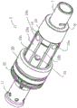
FIG. 2 is a rear isometric view of the connector of FIG. 1;
FIG. 3 is a front isometric view of the connector of FIGS. 1 and 2;
FIG. 4 is a rear isometric view of the connector of FIGS. 1-3 inserted into a hole of a support post with the support post portion shown cut away;
FIG. 5 is a front isometric view of the connector of FIGS. 1-3 inserted into a hole of a support post with the support post portion shown cut away;
FIG. 6 is a front isometric view of the connector of FIGS. 1-3 attached to a bend limiter at the front and a bend stiffener at the rear and inserted into a hole of a support column, with the support column portion shown cut away;
FIG. 7 is a rear isometric view of the connector of FIGS. 1-3 attached to a bend limiter at the front and a bend stiffener at the rear and inserted into a hole of a support column, with the support column portion shown cut away;
fig. 8 is a rear isometric view of the connector of fig. 1-3 with some of the locking elements in a disengaged position;
fig. 9 is a front isometric view of the connector of fig. 1-3 with some of the locking elements in a disengaged position;
fig. 10 is a rear isometric view of the connector of fig. 1-3 with all of the locking elements in a disengaged position;
fig. 11 is a front isometric view of the connector of fig. 1-3 with all of the locking elements in a disengaged position;
FIG. 12 is a transverse cross-sectional view of the connector of FIG. 1 shown at a different angle;
FIG. 13 is a cross-sectional view of a connector according to a second embodiment of the present invention, with the locking element in the engaged position, the cross-section being taken at an angle offset 45 degrees from the lower half of FIG. 17 toward line A-A of FIG. 17;
FIG. 14 is a cross-sectional view of the connector of FIG. 13 shown at the same angle with the locking element in a disengaged position;
fig. 15 is a cross-sectional view of the connector of fig. 13 and 14 shown at the same angle with some of the locking elements in the engaged position and others in the disengaged position;
fig. 16 is a cross-sectional view of the connector of fig. 13-15 shown at the same angle with the locking element in a disengaged position;
fig. 17 is a rear isometric view of the connector of fig. 13-16 with the locking element in an engaged position;
fig. 18 is a front isometric view of the connector of fig. 13-16 with the locking element in an engaged position;
figure 19 is a rear isometric view of the connector of figures 13-16 inserted into the hole of the support post with the support post shown partially cut away;
figure 20 is a front isometric view of the connector of figures 13-16 inserted into the hole of the support post with the support post shown partially cut away;
FIG. 21 is a front isometric view of the connector of FIGS. 13-16 attached to the bend limiter at the front and to the bend stiffener at the rear and inserted into a hole of a support post, the support post shown partially cut away;
FIG. 22 is a rear isometric view of the connector of FIGS. 13-16 attached to the bend limiter at the front and to the bend stiffener at the rear and inserted into a hole of a support post, the support post shown partially cut away;
fig. 23 is a rear isometric view of the connector of fig. 13-16 with all of the locking elements in a disengaged position;
fig. 24 is a rear isometric view of the connector of fig. 13-16 with some locking elements in a disengaged position and some locking elements in an engaged position;
fig. 25 is a rear isometric view of the connector of fig. 13-16, with the locking element in a disengaged position; and
fig. 26 is a rear isometric view of the connector of fig. 13-16, with the sleeve not shown.
Detailed Description
Referring to fig. 1 to 12, there is shown a subsea connector 1 of a first embodiment for connecting a cable (not shown) to a support column 3 (as shown in fig. 4-7) of a wind turbine generator.
The connector 1 is a male part arranged to be inserted into a female part in the form of a bore 4 extending through the support column 3 at an oblique angle. In the alternative (not shown), the connector may extend into a specially adapted J-shaped tube formed with a flange (inwardly) behind the guide cone, the flange acting as the bore.
The connector 1 comprises a hollow load bearing mandrel 5 through which a cylindrical bore 6 extends axially along a main (longitudinal) axis X of the connector 1. The hole 6 is intended to receive the cable (not shown) so that the connector 1 can connect the cable (not shown) to the support column 3. It will be appreciated by those skilled in the art that other subsea elements, such as riser cables (risers) or umbilicals, may be connected with the same type of connector 1 by varying the size of the bore 6.
The mandrel 5 may have a front and a rear. At the rear, a connection device 11 is provided for connection to a bend stiffener 12 or the like. At the front, a nose cone (nose cone)7 is attached to the spindle 6, the front of the nose cone 7 extending forwardly from the spindle 5 into the continuation hole 6, through which hole 6 a cable (not shown) extends in use. A pair of slots 8 are formed on the outside of this forward extending portion of the nose cone. A forwardly extending bend limiter 9 (shown in figures 6 and 7) is attached to guide the cable within the support column 3.
The rear of the nose cone 7 comprises a sleeve 10, which sleeve 10 is concentric with the mandrel 5 towards the front of the mandrel 5 and is radially spaced from the outside of the mandrel 5. Thus, an annular gap is provided between the sleeve 10 of the nose cone 7 and the outer cylindrical surface of the mandrel 5. The annular gap provides a guide into which the forward end of the cage (or ball cage segments) 13 extends. The cages 13 are formed as segments (segments) of a cylindrical tube, are arranged side by side around the mandrel 5, and each cage extends along a longitudinal axis.
The front end of the cage 13 is stepped to form a protrusion 2 extending into the annular gap and has a reduced thickness relative to the body of the cage, so that overall the array of cages 13 has an inner diameter corresponding to the outer diameter of the mandrel and the outer diameter of the array of cages corresponds to the outer diameter of the sleeve 10 of the nose cone. On the other hand, the projection 2 at the front end of the holder has an inner diameter equal to that of the body, but has an outer diameter corresponding to the inner diameter of the sleeve. Therefore, these holders 13 can freely slide back and forth, being restricted by the sleeve 10. In this embodiment, eight cages 13 are provided, each having a bore 14 therethrough. Each aperture 14 is sized and shaped to capture a locking element in the form of a locking ball 15 in this manner: a portion of the ball 15 may extend radially outward from the aperture 14 but may not completely escape from the aperture 14. This is achieved by slightly reducing the diameter of the bore 14 in its radially outer region.
The holders 13 are divided into two types, a first type 13a (shown in fig. 12) having holes 14 toward the front of the holder 13 a; the second type 13b (shown in fig. 1) has a hole 14 towards the rear of the cage 13 b. These types of cages 13a, 13b alternate around the connector 1 so that one ball 15 is in the hole 14 towards the front of the cage 13a and its adjacent ball is in the hole towards the rear of the cage 13 b. Thus, two rows of circumferential balls 15 are formed; a row of front balls 15a and a row of rear balls 15 b.
Because these types of cages 13a, 13b are arranged alternately, the balls 15a in the front row are longitudinally offset with respect to the balls 15b in the rear row, except that the two rows of balls 15a, 15b are longitudinally spaced.
In order to extend the balls 15a, 15b to their engaged/deployed position projecting radially from the hole 14 and to retract to their disengaged/stowed position not projecting, the mandrel on which the cage 13 is mounted is provided with ramps 16 formed in grooves 17 on its outer surface, having an axially tapered surface along which the balls 15 can roll. In the present embodiment, a single groove 17 is provided for each ball 15. Alternatively, however, a pair of circumferentially extending grooves 17 may be formed around the entire circumference of the spindle 5, one for the rear set of balls 15b and one for the front row of balls 15 a. The recess 17 is formed with a ramp 16 in the form of a transition surface from a lower region 18 (with a smaller diameter) to an upper region 19 (with a larger diameter), wherein, in the lower region 18, the locking element is in the disengaged position; in the upper region 19, the locking element is in the engaged position. The upper region 19 of the groove 17 is formed as a flat surface parallel to the cage 13 but may take the form of a depression to assist in retaining the deployed balls 15 in the engaged position.
The rear portion of the holder 13 is retained within a tubular housing 20 having a frusto-conical front end or "stop" 32. A series of cavities 21 are formed around the connector 1 between the tubular housing 20 and the mandrel 5, one cavity 21 being aligned with each of the holders 15. The cavity 21 is formed by a recess (recess) in the tubular housing 20 and a corresponding recess/groove (groove) in the spindle 5. Each cage 15 can slide back into its corresponding cavity 21. A hole 22 is provided at the rear of each cavity 21 and a rod/pin 23 connected to the rear of each respective cage 15 may extend through the hole 22. Around the rod 23 near its front end a spring element in the form of a helical compression spring 24 is connected. The stop surface 25 is provided by a radially outwardly extending flange 26 formed on the spindle 5, which flange 26 forms part of the rear wall of the cavity 21. A coil spring 24 is also secured in place at its rear portion by attachment to the tubular housing 20.
Each spring element 24 resiliently biases the corresponding rod 23 (and thus the corresponding holder 13) forward. The bias will thus force the ball 15 to move up the ramp surface 16 to an engaged position on the upper region 19 of the recess 17. To the rear of the flange 26, a release means in the form of a release collar 27 is slidably mounted on the mandrel 5. The release collar 27 is provided with apertures (apertures/boris) 28 corresponding to the apertures 22, the rod 23 extending through the apertures 28. The bore 28 through the release collar 27 is provided with a counter/counter bore at its rear and the stem 23 is provided with extensions in the form of flares at its rear which extend into a counter/counter bore 30. In this embodiment, the rear located expansion is provided by attaching a countersunk screw/bolt 29 to the rod 23.
This arrangement means that when the resilient bias of the spring elements 24 is overcome and the respective holders 13 can move rearwardly independently of one another, and in so doing, the rods 23 moving the holders 13 will slide out of the rear of the release collar 27.
As shown in fig. 12, the connection of the rod/pin 23a at the rear of the first type of cage 13a is slightly different. Again spring elements 24 are provided to bias the respective levers 23a forwardly and apertures (apertures/balls) 28 corresponding to the apertures 22 through which the levers 23a extend are provided through the release collar. Again, a bore 28 through the release collar 27 is countersunk at its rear and a countersunk screw/bolt 29 is attached to the rods 23a so that rearward movement of the release collar can move the rods 23a rearward (and thus the cage 13a rearward). However, the forward end of the bore 28 through the release collar 27 is also provided with a counter bore 34, and the stem 23a is provided with an integral flange 35 which engages the counter bore 34. Thus, the release collar 27 is effectively clamped between the flange 35 and the expanded portion of the countersink/grub screw/bolt 29, enabling the release collar 27 and the retainer 13a to move simultaneously; the rearward movement of the retainer 13a forces the release collar to move rearwardly in the same manner as the rearward movement of the release collar moves the retainers 13a, 13b rearwardly. .
In the operative position, the release collar 27 is mounted adjacent the rear of the flange 26 and is held in the operative position by the resilient bias of the spring 24. However, as mentioned above, the collar 27 is mounted so as to be able to slide on the mandrel 5. The release collar 27 is provided with gripping means 31 in the form of a circumferential groove, and similar gripping means 33 in the form of a circumferential groove are formed on the tubular housing 20. Thus, a hydraulic horseshoe clamp (not shown) or similar actuator mounted to the gripping device by an ROV (remotely operated vehicle) may be connected. Thus, the actuator may pull the release collar 27 back against the resilient bias to the release position. Pulling the release collar 27 rearwardly pulls the pin/rod 23 rearwardly (and therefore the expanded end of the screw/bolt 29) thereby pulling the cage 13 rearwardly and allowing the balls 15 to move to the disengaged/stowed position.
In use, a cable (not shown) is passed through the bore (bore)6 of the mandrel 5 and attached to the machine 1 by conventional means. The bend limiter 9 is then attached to the nose cone and the bend stiffener 12 is attached to the rear of the connector 1.
The front of the cable (not shown) extending out of the front of the connector is then pulled into the support column 3 of the wind turbine generator (or the like) through a hole 4 extending through the support column 3 at an oblique angle (e.g. 60 degrees). As shown in fig. 1, 2, 3 and 5, when the cable is pulled in, the resilient spring element 25 will push the cage 13 forward and thus the balls 15 (radially outward) into said engaged position. Once the nose cone 7 begins to enter the hole, one or both of the balls 15a in the previous row will contact the outer edge of the hole 4 because the hole is at an oblique angle. The holes 4 are typically inclined downwardly so that the lowermost balls 15a will contact the outer edge of the holes 4 first.
When the cable (not shown) is continued to be pulled into the support leg 3, pulling the connector 1 inwards, the balls 15a abutting the edge will be pushed backwards, thereby forcing the cage 13a to which they are attached to move backwards against the resilient bias of their respective springs 24. Since the cages 13a are operatively interconnected by the release collar, the spring bias of all cages must be overcome at once to move the release collar rearwardly as the balls 15a moving through the apertures 4 move rearwardly and inwardly down the ramps 16.
As the connector 1 continues to move through the aperture, the balls 15a in the upper region of the front row will contact the outer edge of the aperture 4 and move inwardly. Once all the balls in the front row have passed through the aperture 4, the resilient bias of the helical spring 24 will force the cage 13a to move forwardly, thereby moving the balls 15a forwardly, up the ramps 16 and outwardly to the engaged position shown in figures 8 and 9. This forward movement of all the cages 13a with the front row of balls 15a also causes the release collar to move forward, providing a visual indication outside the support post 3 that the first row of balls 15a has all passed the inner edge of the aperture.
Fig. 8 and 9 show such a connector: all of its balls 15a are in the engaged position, having passed through the holes 4; its rear ball is visible in the disengaged position, as is the case when the front ball 15a has passed the inner edge of the hole 4, while the rear ball 15b is about to pass the hole, having been pushed backwards (and inwards) by the rear edge of the hole 4. Some of the balls 15b in the rear row may remain in the bore 4 (between its inner and outer edges) depending on the angle of the bore 4 even if the connector 1 has been pulled into its maximum extent at which the tubular housing 20 (in particular its frusto-conical front surface 32) will abut against the wall of the support column 3 to prevent over-insertion.
With the support columns 3 appropriately angled and of appropriate thickness and the rows of balls 15 appropriately spaced, full insertion of the connector 1 will result in three balls 15 engaging the inner edge thereof inside the hole in the engaged position, with the other balls 15a inside the connector but not engaging the edge, and the other balls 15b outside the hole 4, not participating in the engagement. Depending on the direction in which the connector 1 is pulled through, the three balls 15 will be two balls from the front row of balls 15a and one ball from the rear row of balls 15b, or two balls 15b from the rear row of balls 15b and one ball from the front row of balls 15 a. This creates three points of contact on the inner edge of the hole, providing a strong and stable connection as shown in fig. 6 and 7.
Once the balls 15 engage inside the inner edge of the hole 4, the connector cannot be pulled out. This is because pulling on the connector pulls the balls against the inner edge, creating a downward (i.e., radially inward) and longitudinally forward force on the balls. However, the groove 17 is tapered such that the diameter of the transition surface of the ramp 16 decreases in the longitudinally rearward direction. Therefore, the balls 15 cannot be forced down the ramps 16, and the connector is firmly connected to the support column 3.
The connector 1 may be connected to another female part, e.g. a J-tube (not shown), as mentioned above, provided that appropriate modifications are made, e.g. providing a flange (flange) to replicate the (reproduction) bore 4. The connector 1 may even be connected to a J-tube with flanges which are not necessarily angled but perpendicular to the rows of balls 15. Either or both of the front or rear rows of balls 15 may engage behind the flange.
To remove the connector 1 from the aperture 4 (or other female component) in the support post 3, the release collar 27 is pulled back (e.g., by an actuator such as a horseshoe clamp) as shown in fig. 10 and 11. This rearward movement overcomes the resilient bias of all the springs 24 and pulls all the rods 23 and the cages 13a, 13b rearward-which in turn forces the balls 15 to move rearward and radially inward along the ramps 16 down to the lower region 18 of the recess 17. As the balls 15 move into the disengaged/stowed position (in which the balls 15 are no longer forced radially outwardly), the connector 1 can be pulled out of engagement with the bore 4 for maintenance/replacement or the like. Once the release collar is no longer pulled away from the tubular housing 20, the resilient bias of the spring 24 will return it into the operative position adjacent the flange 26.
Referring to fig. 13 to 25, a second embodiment of a subsea connector 201 for connecting a cable (not shown) to a support column 203 (as shown in fig. 19 to 22) of a wind turbine generator is shown.
The connector 201 is a male part arranged to be inserted into a female part in the form of a bore 204 extending through the support 203 at an oblique angle. In the alternative (not shown), the connector may extend into a specially adapted J-shaped tube formed with a flange (inwardly) behind the guide cone, the flange acting as the bore.
The connector 201 comprises a hollow load bearing mandrel 205, a cylindrical bore 206 extending axially through the hollow load bearing mandrel 5 along a main (longitudinal) axis X of the connector 201. The aperture 206 is intended to receive a cable (not shown) so that the connector 201 can connect the cable (not shown) to the support column 203. It will be appreciated by those skilled in the art that other subsea elements, such as riser cables (risers) or umbilicals, may be connected with the same type of connector 201 by varying the size of the bore 206.
The mandrel 205 has a front and a rear. At the rear, a connection device 211 is provided for connection to a bend stiffener 212 or the like. At the front, a nose cone 207 is formed at the front of the mandrel 206. The nose cone 207 extends forwardly to a bore 206 in continuation of the mandrel 205, through which bore 206 the cable (not shown) extends in use. A pair of slots 208 are formed on the outside of this forward extending portion of the nose cone. A forwardly extending bend limiter 209 (shown in fig. 21 and 22) is attached to guide the cable in the support column 203.
The rear of the nose cone 207 is defined by a radially outwardly extending annular stop surface 250. A sleeve 210 concentric with the spindle 205 and spaced radially outwardly therefrom is provided extending rearwardly from the annular stop surface. Thus, an annular gap is provided between the sleeve 210 and the outer cylindrical surface of the mandrel 205. The annular gap provides a guide in which the cage (or ball cage segment) 213 extends. As shown in fig. 26, the front retainer 213a positioned toward the front of the connector 201 is provided as a cylindrical tube; while the rear retainers 213b are formed as segments of a cylindrical tube, arranged side-by-side around the spindle 205, and each extending along a longitudinal axis.
The array of holders 213 has an inner diameter corresponding to the outer diameter of the mandrel 205 and the outer diameter of the array of holders corresponds to the inner diameter of the sleeve 210 for movement within the annular gap between the mandrel 205 and the sleeve 210. In this embodiment, a single forward holder 213a is provided, and four rearward holders 213b are provided; the single forward cage 213a includes four circumferentially spaced apertures 214, and each rearward cage 213b has a single aperture 214 therethrough. The holes are evenly spaced around the front cage 213a, and the rear cage 213b is similarly evenly spaced, positioned such that its holes 214 are disposed at an oblique angle of 45 degrees to those of the front cage 213 a. Thus, in the case where one ball 215 is located in the hole 214 toward the front of the connector 201, its adjacent ball is located in the hole 214 toward the rear of the connector 201. Thus, two rows of circumferential balls 215 are formed; a row of front balls and a row of rear balls. Of course, other angles of the balls are conceivable by those skilled in the art, or indeed additional rows at other angles.
In addition to longitudinally spacing the rows of balls 215a, 215b, the balls 215a in the front row are longitudinally offset relative to the balls 215b in the rear row.
Each aperture 214 is sized and shaped to capture a locking element in the form of a locking ball 215 in this manner: a portion of the balls 215 may extend radially outward from the bore 214 and be free to move radially inward and outward, but be constrained in a circumferential (fore-aft) direction. The sleeve 210 is provided with a plurality of grooves (slots)251, the plurality of grooves 251 corresponding in position to the region over which the balls extend. The grooves 251 extend axially so as to allow the balls to move freely in the axial direction (forward and backward) simultaneously (in tandem) with the cages 213a, 213 b. However, the grooves are shaped and sized to limit movement in the radial direction so that the balls 215 cannot escape completely from the sleeve 210. This is achieved by slightly reducing the width of the groove 251 in its radially outer region.
As described above, the holder 213 is divided into two types, the first type 213a having the hole 214 toward the front of the holder 213 a; the second type 213b has a hole 214 towards the rear of the holder 213 b. A plurality of second type of retainers 213b are spaced around the connector 201 and the first type of retainer is located in front of it.
In addition to longitudinally spacing the rows of balls 215, the balls 215a in the front row are longitudinally offset from the balls 215b in the rear row. Since the balls in the front cage 213a are axially restrained by the same member, the balls move simultaneously with each other when the cage 213a moves back and forth. On the other hand, the balls 215 in the second type of cage 213b can move independently.
In order to extend the balls 215a, 215b into an engaged/deployed position, in which the balls 215a, 215b protrude radially from the hole 214 and the slot 251, and to retract into a disengaged/stowed position, in which the balls 215a, 215b do not protrude from the slot 251, the spindle 205, on which the cage 213 is mounted, is provided with a ramp 216 formed in a groove 217 on the outer surface of the spindle 205, the ramp 216 having an axially tapered surface along which the balls 215 can roll. In this embodiment, one groove 217 is provided for each ball 215. Alternatively, however, a pair of circumferentially extending grooves 217 may be formed around the entire circumference of the spindle 205, one for each set of rear balls 215b and one for each set of front balls 215 a.
The groove 217 is formed with a ramp 216 in the form of a transition surface from a rear lower region 218 (with a smaller diameter) to an upper region 219 (with a larger diameter), wherein in this rear lower region 218 the locking element 215 is in the disengaged position; in this upper region 219, the locking element is in the engaged position. The upper region 219 of the groove 217 is formed as a flat surface parallel to the cage 213, but may take the form of a depression to assist in retaining the deployed balls 215 in the engaged position.
Each groove 217 of the second embodiment is provided with a second lower region 252 compared to the first embodiment, the second lower region 252 having a smaller diameter than the upper region 219 and being located in front of the upper region 219, the balls 215 being movable in the "disengaged" position to the second lower region 252 (as shown in figure 16).
The rear of the cage 213 is attached to a rod/pin 223, each rear cage 213b connected to a single rod/pin 223, and a front cage connected by a series of rods/pins 223, each of which extends into a tubular housing 220 having a frusto-conical front end or "stop" 232.
The drawing is simplified, but again a series of cavities 221 are formed around the connector 201 between the tubular housing 220 and the mandrel 205, one cavity 221 being aligned with each cage bar/pin 223. As the cage 213 slides rearward, each rod/pin 223 may slide rearward into its corresponding cavity. At the rear of each cavity 221 there is provided a hole 222 through which a rod/pin 223 connected to the rear of each respective cage 213 may extend.
A spring element in the form of a helical compression spring (not shown) is attached around each rod 223 near its front end in the same manner as in the first embodiment. The stop surface (not shown) is provided by a radially outwardly extending flange 226 formed on the spindle 205, which flange 226 forms part of the rear wall of the cavity 221. A coil spring (not shown) is fixed in place at its rear portion by being connected to the tubular housing 220.
Each spring element (not shown) resiliently biases the corresponding rod 223 (and thus the corresponding holder 213) forward. Thus, the bias will force the ball 215 to move up the ramp surface 216 to an engaged position on the upper region 219 of the recess 217. To the rear of the flange 226, a release means in the form of a release collar 227 is slidably mounted on the spindle 205. The release collar 227 is provided with apertures (apertures/bones) 228 corresponding to the apertures 222, the rods 223 extending through the apertures 228. The hole 228 through the release collar 227 is provided with a counter/counter bore at the rear and the rod 223 is attached to the release collar 227 by means of countersunk screws/bolts 229, which countersunk screws/bolts 229 are provided at their rear with an extension in the form of a flare that extends into the counter/counter bore 230.
The rod/pin 223 connected to the rear cage 213a is connected via a pair of countersunk bolts, one of which is connected at its head to the other, and which is disposed in a counterbore/counterbore 253 (the counterbore/counterbore 253 being disposed forward of the release collar 227) thereby tethering the release collar to the front cage so that under normal conditions the rod/pin follows as the balls 215 of the front cage 213a move between the engaged and disengaged positions.
On the other hand, the connection between the rods 223 attached to the rear retainers 213b is such that the respective retainers 213b can move backwards independently of each other when the spring bias of the spring elements is overcome, and in doing so, the rods 223 of the moving retainers 213 slide out of the rear of the release collar 227.
In the engaged position, the release collar 227 is mounted adjacent the rear of the flange 226 and is held in the operative position by the resilient bias of the spring. However, as mentioned above, the collar 227 is mounted to be able to slide over the mandrel 205. The release collar 227 is provided with gripping means 231 in the form of a circumferential groove, and similar gripping means 233 in the form of a circumferential groove are formed on the tubular housing 220. Thus, a hydraulic horseshoe clamp (not shown) or similar actuator mounted to the gripping device by an ROV (remotely operated vehicle) may be connected. Thus, the actuator can pull the release collar 227 back against the resilient bias to the release position. Pulling back on release collar 227 (due to the expanded end of screw/bolt 229) pulls back on pin/rod 223, thereby pulling back on cage 213 and allowing balls 215 to move to the disengaged/stowed position.
This enables non-destructive removal. However, to achieve that removal can be done without the use of an ROV, the bolts 229 connecting the rod to the release collar are tension bolts (which can break under a certain load (e.g. 10 tons). Thus, a pull head can be used to pull/push the connector 201 out of the support 203 and, provided sufficient force is applied to overcome the pull limit of the bolt, the balls 215 move forwardly and radially inwardly to the disengaged position shown in fig. 16 and 25.
In use, a cable (not shown) is passed through the bore 206 of the mandrel 205 and attached to the linking machine 201 by conventional means. The bend limiter 209 is then attached to the nose cone and the bend stiffener 212 is connected to the rear of the connector 201.
The front of the cable (not shown) extending out of the front of the connector is then pulled into the support column 203 of the wind turbine generator (or the like) through a hole 204 extending through the support column 203 at an oblique angle (e.g. 60 degrees). When the cable is pulled in, the resilient spring element 25 pushes the cage 213 forward and thus the balls 215 (radially outward) into the engaged position, but not beyond, as shown in fig. 13, 17, 18, 19 and 20. Once the nose cone 207 begins to enter the hole, one or both of the ball front rows 215a will contact the outer edge of the hole 204 because the hole is at an oblique angle. The holes 204 are generally sloped downward so that the lowermost balls 215a will contact the outer edge of the holes 204 first.
As the cable (not shown) continues to be pulled into the support column 203, pulling the connector 201 inwardly, the balls 215a abutting the edge will be pushed rearwardly, forcing the cage 213a to which they are attached to move rearwardly against the resilient bias of their respective springs (not shown) to move the release collar 227 rearwardly as the balls 215a moving through the aperture 204 move rearwardly and inwardly down the ramp 216.
As the connector 201 continues to move through the hole, the balls 215a in the upper region of the front row will contact the outer edge of the hole 204 and move inwardly. Once all of the balls 215 in the front row have passed through the apertures 204, the resilient bias of the helical spring will force the cage 213a forwardly, thereby moving the balls 215a forwardly, up the ramps 216 and outwardly to the engaged position. This forward movement of the cage 213a with the balls 215a in the forward row also causes the release sleeve to move forward, providing a visual indication outside the support column 203 that the first row of balls 215a has all passed through the inner edge of the aperture.
Fig. 15 shows such a connector: its front ball 215a in the engaged position, having passed through the hole 204; its rear ball 215b is visible in the disengaged position, as is the case when the front ball 215a has passed the inner edge of the hole 204, and the rear ball 215b is about to pass the hole, having been pushed rearward (and inward) by the rear edge of the hole 204. Even once the connector 201 has been pulled to its maximum extent at which the tubular housing 220, and in particular its frusto-conical front surface 232, will abut against the wall of the support column 203 to prevent over-insertion, some of the balls 215b in the rear row may remain in the bore 204 (between its inner and outer edges), depending on the angle of the bore 204.
With the support posts 203 appropriately angled and of appropriate thickness and the rows of balls 215 appropriately spaced, full insertion of the connector 201 will result in three balls 215 being located inside the hole in the engaged position, engaging the inner edge thereof, and the other balls 215a being located inside the connector but not engaging the edge, and the other balls 215b being located outside the hole 204 and not participating in the engagement. Depending on the direction in which the connector 201 is pulled through, the three balls 215 will be two balls from the front row of balls 215a and one ball from the back row of balls 215b, or two balls 215b from the back row of balls 215b and one ball from the front row of balls 215 a. This creates three contact points on the inner edge of the hole, providing a secure and stable connection.
Once the balls 215 engage within the inner edge of the bore 204, the connector cannot be accidentally pulled out. This is because pulling on the connector pulls the balls against the inner edge, creating a downward (i.e., radially inward) and longitudinally forward force on the balls. However, the balls 215 are located on the platform surface 219 and cannot move onto the grooves 217, the grooves 217 being tapered such that the diameter of the transition surface of the ramp 216 decreases in a longitudinally rearward direction. Thus, the balls 215 cannot be forced down the ramps 216 and the connector is securely connected to the support 203.
Under normal conditions (including relatively extreme subsea conditions) where relatively low outward forces may be applied to the connector 201, the balls 215 cannot move forward onto the lower region 252 (the disengaged position) because the cage is operatively connected to the release collar 227 in a manner that cannot move beyond the predetermined forward position (i.e., the position where the expanded portion of the bolt 229 abuts the counterbore of the release collar).
However, as described above, if it is desired to permanently remove the connector 201, a pull-in head (not shown) may be connected to the connector and the connector may be pulled/pushed out of the post by using a very large force (e.g., greater than 50000N, such as 10 tons) to break the connection between the cage 213 and the release collar 227 and allow the balls 215a, 215b to move forward and radially inward into the disengaged position 252.
The connector 201 may be connected to another female component (e.g., a J-tube (not shown)), as mentioned above, with appropriate modifications, e.g., providing a flange to replicate the aperture 204. The connector 201 may even be connected to a J-tube with flanges that are not necessarily angled, but are perpendicular to the rows of balls 215. Either or both of the front or rear rows of balls 215 may engage behind the flange.
To temporarily remove the connector 201 from the aperture 204 (or other female component) in the support post 203, the release collar 227 is pulled back (e.g., by an actuator, such as a horseshoe clamp), as shown in fig. 14 and 23. This rearward movement overcomes the resilient bias of all the springs and pulls all the rods 223 and cages 213a, 13b rearward-which in turn forces the balls 215 to move rearward and radially inward along the ramps 216 down to the lower region 218 of the recess 217. As the balls 215 move to the disengaged/stowed position (where the balls 215 are no longer forced radially outward), the connector 201 may be pulled out of engagement with the bore 204 for maintenance/replacement, etc. Once the release collar is no longer pulled away from the tubular housing 220, the resilient bias of the spring (not shown) will return it to the operative position adjacent the flange 226.
The above embodiments are described by way of example only. Various modifications are possible without departing from the scope of the invention as defined in the appended claims.
Claims (63)
1. An elongated connector having a plurality of locking elements disposed on a ramp surface and retained in at least one cage on the connector, whereby the at least one cage is movable to move the locking elements along the ramp surface between an engaged position and a disengaged position; characterized in that a sleeve is covered on the radial outside of the holder and has a groove thereon, which groove corresponds in position to the region over which the locking element extends, whereby the locking element is moved from the disengaged position to the engaged position radially through the groove.
2. The elongated connector according to claim 1 wherein said slot extends axially and said locking element moves axially when moved radially through said slot.
3. The elongated connector according to claim 1 or 2 wherein said slot is shaped to retain said locking element in said connector.
4. The elongated connector according to claim 3, wherein at least a portion of said slot has a width less than a width of said locking element.
5. An elongated connector having a plurality of locking elements disposed on a ramp surface and retained in at least one cage on the connector, whereby the at least one cage is movable to move the locking elements along the ramp surface from a disengaged position to an engaged position; the locking element is movable in the at least one cage to another disengaged position.
6. The elongated connector according to claim 5 wherein said locking elements move in the same radial direction from said engaged position to said disengaged position and from said engaged position to said disengaged position.
7. The elongated connector according to claim 6 wherein said locking element moves radially inwardly from said engaged position to said disengaged position and from said engaged position to said disengaged position.
8. The elongated connector according to claims 5, 6 or 7 wherein the locking elements are moved in the same axial direction from the disengaged position to the engaged position and from the disengaged position to the disengaged position.
9. The elongated connector according to any one of claims 5 to 7 wherein the at least one retainer is operatively connected to a portion of the connector to limit movement of the locking element to the engaged and disengaged positions, this operative connection being disconnectable to allow movement to the disengaged position.
10. The elongated connector of claim 9, wherein the at least one retainer is operatively connected to a release collar.
11. The elongated connector according to claim 9 wherein a predetermined force is required to break said operative connection.
12. The elongated connector according to claim 11 wherein a tension bolt, a tension pin, a shear bolt or a shear pin provides said breakable operative connection.
13. The elongated connector according to any one of claims 5 to 7 covered on a radially outer side of the holder with a sleeve having a groove thereon corresponding in position to an area over which the locking element extends, whereby the locking element moves radially through the groove from the disengaged position to the engaged position.
14. A method of disconnecting a submarine cable connected to a generator with a connector according to claim 5 or any claim dependent thereon, the method comprising: applying a predetermined force to force the connector out of the aperture to force the locking element to move from the engaged position to the disengaged position.
15. An elongated connector having a longitudinal axis, a plurality of locking elements disposed on a ramp surface and retained in a plurality of retainers on the connector, whereby the retainers are movable to move the locking elements along the ramp surface between an engaged position and a disengaged position; wherein the plurality of holders are movable independently of each other.
16. The connector of claim 15, a sleeve covering a radially outer side of the retainer, the sleeve having a slot therein corresponding in position to an area over which the locking element extends, whereby the locking element moves radially through the slot from the disengaged position to the engaged position.
17. A connector according to claim 15 or 16, wherein the ramp surface comprises a transition surface from a lower region of the locking element in the disengaged position to an upper region of the locking element in the engaged position.
18. The connector of claim 17, wherein the upper region and/or the lower region is a ramp surface, or a flat surface parallel to the cage, or formed as a depression.
19. The connector of claim 17, wherein the ramp surface tapers axially such that the lower region is toward a rear of the connector and the upper region is toward a front.
20. A connector according to claim 15 or 16, wherein the cage is axially movable.
21. A connector according to claim 15 or 16, wherein the plurality of ramp surfaces are provided by a single ramp extending circumferentially around the connector.
22. A connector according to claim 15 or 16, wherein the locking element is a ball.
23. A connector according to claim 15 or 16, wherein the locking element is arranged to move radially outwardly from the disengaged position to the engaged position, the locking element moving axially upwardly on the ramp surface as the locking element moves radially.
24. A connector according to claim 15 or 16, which is a male part which in use is inserted into a female part in the form of a bore such that the locking element engages with an edge of the bore.
25. A connector according to claim 15 or 16, wherein the or each cage is resiliently biased towards the engaged position.
26. A connector according to claim 25, wherein the resilient bias is provided by a spring or a gas strut.
27. A connector according to claim 15 or 16, wherein the plurality of cages are independently resiliently biased.
28. The connector of claim 15 or 16, wherein the plurality of locking elements and the plurality of cages comprise at least three locking elements and at least three cages; and at least two of the holders are operatively connected for simultaneous movement, but independently of at least one other holder.
29. The connector of claim 15 or 16, wherein the plurality of locking elements and the plurality of cages comprise at least four locking elements and at least four cages; and at least two of the holders are operatively connected holders that move simultaneously but independently of at least two other independent holders, and the at least two other independent holders can move independently of each other and independently of the operatively connected holders.
30. The connector of claim 15 or 16, wherein the plurality of locking elements and the plurality of cages comprise at least six locking elements and at least six cages; and at least three of the holders are operatively connected holders that move simultaneously but independently of at least three other individual holders, and the at least three other individual holders are movable independently of each other and independently of the operatively connected holders.
31. The connector of claim 15 or 16, wherein the plurality of locking elements and the plurality of cages comprise at least eight locking elements and at least eight cages; and at least four of the holders are operatively connected holders that move simultaneously but independently of at least four other individual holders, and the at least four other individual holders are movable independently of each other and independently of the operatively connected holders.
32. A connector according to claim 15 or 16, wherein the locking elements are arranged such that some locking elements are operatively connected by one or more cages and others are moved independently, wherein the independent locking elements and operatively connected elements alternate around the connector.
33. A connector according to claim 25, wherein the locking elements are arranged in at least one row spaced circumferentially around the connector.
34. The connector of claim 33, having a front and a rear, wherein the locking elements are arranged in a front row and a rear row.
35. A connector according to claim 34, wherein the or each cage extends fore and aft and is axially moveable.
36. A connector according to claim 34 or 35, wherein the locking elements in the front row are axially offset relative to the locking elements in the rear row.
37. The connector of any one of claims 25, 34 to 35, wherein the resilient bias biases the cage forward.
38. A connector according to claim 15 or 16, wherein the locking elements are arranged such that the locking elements in the front row are operatively connected and move simultaneously, while the locking elements in the rear row are independently movable.
39. The connector of claim 15 or 16, comprising a release device operatively connected to the cage and operable to move the cage from the engaged position to the disengaged position.
40. A connector according to claim 39, wherein the release means is a release collar.
41. A connector according to claim 40, wherein the collar is provided at a rear of the cage and is connected thereto by a pin which extends through a rear of the collar and is provided with an extension such that rearward movement of the collar moves the pin rearwardly thereby moving the cage rearwardly and hence the locking element to the disengaged position, but rearward movement of the cage only moves the pin through the release collar but not the release collar.
42. A connector according to claim 41, wherein the pin is detachably connected to the release means.
43. A connector according to claim 39, wherein the release means is operable by an ROV.
44. A connector according to claim 39, wherein the connector is provided with a mechanism for remotely operating the release means.
45. A connector according to claim 39, wherein at least one of the holders or a plurality of holders is fixedly attached to the release means to move simultaneously with the release means.
46. A connector according to claim 45, wherein at least one cage or a plurality of cages are fixedly attached to the release device by frangible fasteners.
47. A connector according to claim 46, wherein a flange is provided on a pin attached to the operatively connected cage, the flange being arranged to interact with a front portion of the release means to move the release means simultaneously with the operatively connected cage.
48. A connector according to claim 15 or 16, comprising a hollow body on which the cage and locking element are mounted.
49. The connector of claim 48, wherein the ramp is formed on the hollow body.
50. The connector of claim 48, comprising a nose comprising means for connecting to a bend stiffener to prevent excessive bending of a cable extending through and out of the hollow body.
51. The connector of claim 50, including a bend stiffener connected to the nose.
52. A connector according to claim 48, comprising a tail portion comprising means for connecting to a bend stiffener to prevent excessive bending of a cable extending to the rear of the hollow body and through the hollow body.
53. A connector according to claim 15 or 16, comprising a housing having a frusto-conical stop surface arranged to abut a support post.
54. A connector according to claim 15 or 16, which is a subsea connector.
55. A connector according to claim 15 or 16, which is a subsea connector for connecting a subsea cable to a wind turbine generator.
56. A method of connecting a submarine cable to a generator, the method comprising: attaching a cable to a connector according to any of claims 1 to 52 and 54-55 and pulling the cable through a hole in a post or into a female connector having a ridge behind which the locking element is engageable such that the locking element within the holder moves from a disengaged position to an engaged position.
57. The method of claim 56, wherein the female connector is a guide cone in a J-shaped tube having a rim with at least one internal flange.
58. The method of claim 56, wherein the holes are at an oblique angle.
59. The method of claim 56, wherein the connector includes a housing having a frustoconical stop surface disposed adjacent a support post, the locking elements being disposed in a front row and a back row, and such that at least one element of the front row and at least one element of the back row engage an edge of the hole in the support post at an oblique angle.
60. The method according to claim 59, wherein the locking element is arranged such that two elements of the front row and one element of the back row engage with the edge of the hole or two elements of the back row and one element of the front row engage with the edge of the hole.
61. A method of disconnecting a submarine cable connected to a generator with a connector according to any one of claims 1 to 55; the method comprises the following steps: moving the cage to move the locking element from the engaged position to the disengaged position.
62. The method of claim 61, wherein the connector comprises a release collar, and the method comprises: moving the release collar to move the cage to move the locking element from the engaged position to the disengaged position.
63. A method of connecting and disconnecting a connector, wherein the connecting is performed according to any one of claims 56 to 60 and the disconnecting is performed according to any one of claims 14, 61 and 62.
Applications Claiming Priority (5)
| Application Number | Priority Date | Filing Date | Title |
|---|---|---|---|
| GB1518829.5A GB2543574B (en) | 2015-10-23 | 2015-10-23 | Connector with independently movable cages |
| GB1518829.5 | 2015-10-23 | ||
| GB1601087.8 | 2016-01-20 | ||
| GB1601087.8A GB2543588B (en) | 2015-10-23 | 2016-01-20 | Connector |
| PCT/GB2016/053247 WO2017068343A1 (en) | 2015-10-23 | 2016-10-19 | Connector |
Publications (2)
| Publication Number | Publication Date |
|---|---|
| CN108474397A CN108474397A (en) | 2018-08-31 |
| CN108474397B true CN108474397B (en) | 2021-08-13 |
Family
ID=55130164
Family Applications (1)
| Application Number | Title | Priority Date | Filing Date |
|---|---|---|---|
| CN201680062004.XA Active CN108474397B (en) | 2015-10-23 | 2016-10-19 | Connector with a locking member |
Country Status (10)
| Country | Link |
|---|---|
| US (1) | US11846314B2 (en) |
| EP (2) | EP3365563B1 (en) |
| JP (3) | JP6889168B2 (en) |
| KR (1) | KR102666426B1 (en) |
| CN (1) | CN108474397B (en) |
| AU (1) | AU2016342549B2 (en) |
| BR (1) | BR112018007941A2 (en) |
| DK (1) | DK3365563T3 (en) |
| GB (3) | GB2543574B (en) |
| WO (1) | WO2017068343A1 (en) |
Families Citing this family (14)
| Publication number | Priority date | Publication date | Assignee | Title |
|---|---|---|---|---|
| GB2543574B (en) | 2015-10-23 | 2017-12-20 | Balltec Ltd | Connector with independently movable cages |
| GB2546066B (en) * | 2015-12-01 | 2022-03-16 | Crp Subsea Ltd | Protection assembly for an elongate member deployed underwater |
| GB201715211D0 (en) * | 2017-09-20 | 2017-11-01 | Tekmar Energy Ltd | Protection device, assembly and method |
| GB2569533B (en) * | 2017-12-15 | 2021-01-27 | Trelleborg Offshore Uk Ltd | Protection assembly for an elongate member deployed underwater |
| CN107906289A (en) * | 2017-12-22 | 2018-04-13 | 新乡平原航空液压设备有限公司 | Adapter assembly and its female connector, pin end |
| GB2570651B (en) * | 2018-01-30 | 2022-04-06 | First Subsea Ltd | Mounting device for an elongate flexible member |
| GB2573264B (en) * | 2018-03-12 | 2022-01-12 | First Subsea Ltd | Pull head connector |
| US10681834B1 (en) * | 2019-03-26 | 2020-06-09 | Quanta Computer Inc. | Removable cable arm bracket |
| CN111668777B (en) * | 2020-07-01 | 2022-04-05 | 广东电网有限责任公司 | Cable conduit |
| CN114687344A (en) * | 2020-12-25 | 2022-07-01 | 连云港华云桩业有限公司 | Seawater corrosion resistant internal clamping type mechanical locking device |
| US20220316512A1 (en) * | 2021-03-30 | 2022-10-06 | Yoke Industrial Corp. | Expansion anchoring device |
| GB202104953D0 (en) * | 2021-04-07 | 2021-05-19 | Advanced Insulation Ltd | Locating method |
| GB202104947D0 (en) * | 2021-04-07 | 2021-05-19 | Advanced Insulation Ltd | Retaining element |
| GB202104952D0 (en) * | 2021-04-07 | 2021-05-19 | Advanced Insulation Ltd | Removal method |
Family Cites Families (26)
| Publication number | Priority date | Publication date | Assignee | Title |
|---|---|---|---|---|
| GB579838A (en) * | 1944-05-18 | 1946-08-16 | Reginald Arthur William Spoone | Improvements relating to pipe and cable couplings |
| DE1115998B (en) * | 1958-03-10 | 1961-10-26 | Otto Bilz | Plug-in coupling for hose lines under pressure |
| US3019502A (en) | 1958-07-23 | 1962-02-06 | Henry J Frost | Locking device for oil well drill rods or pipes |
| US3266825A (en) * | 1963-10-16 | 1966-08-16 | Seaton Wilson Mfg Co | Quick-connect pipe coupling |
| US3267963A (en) * | 1963-11-26 | 1966-08-23 | Metro Hydraulics Inc | Hydraulic coupler |
| DE1529088A1 (en) * | 1966-09-12 | 1969-12-18 | Metallwerk Gaebler & Co Gmbh | Safety gas connection fitting for plug connection |
| GB8406580D0 (en) * | 1984-03-13 | 1984-04-18 | Walmsley O | Pipe connector |
| FR2618862B1 (en) * | 1987-07-27 | 1989-10-27 | Hassid Jean Pierre | DEVICE FOR ASSEMBLING TUBES OR THE LIKE HAVING A HOLLOW HOUSING OF CYLINDRICAL OR SIMILAR FORM |
| JPH04105295A (en) | 1990-08-23 | 1992-04-07 | Fujitsu Ltd | Semiconductor storage device |
| JP2536574Y2 (en) * | 1991-02-20 | 1997-05-21 | 株式会社ハーマン | Gas fittings |
| DE9204570U1 (en) | 1992-04-03 | 1992-06-11 | Erwin Halder Kg, 7958 Laupheim, De | |
| JP2909020B2 (en) * | 1996-06-11 | 1999-06-23 | ナスコフィッティング株式会社 | Pipe fittings |
| JPH10299968A (en) * | 1997-04-18 | 1998-11-13 | Bridgestone Flowtech Corp | Pipe joint structure |
| GB0229424D0 (en) * | 2002-12-18 | 2003-01-22 | Bsw Ltd | A connector |
| JP4255274B2 (en) * | 2002-12-19 | 2009-04-15 | 東亜高級継手バルブ製造株式会社 | Pipe fitting |
| FR2876775B1 (en) * | 2004-10-14 | 2006-12-08 | Staubli Faverges Sca | MALE PART OF A QUICK COUPLING, THIS QUICK CONNECTION AND SET OF TWO SUCH QUICK COUPLINGS |
| GB0506406D0 (en) | 2005-03-30 | 2005-05-04 | Crp Group Ltd | Connector |
| GB0507518D0 (en) * | 2005-04-14 | 2005-05-18 | Balltec Ltd | A connector |
| JP2006307972A (en) * | 2005-04-28 | 2006-11-09 | Ntn Corp | Direct acting one-way clutch |
| US7552764B2 (en) | 2007-01-04 | 2009-06-30 | Nabors Global Holdings, Ltd. | Tubular handling device |
| GB2463940C (en) * | 2008-10-03 | 2012-07-18 | Tekmar Energy Ltd | Protection assembly for elongate flexible member and method of installation of such member |
| GB2505901A (en) | 2012-09-13 | 2014-03-19 | Infastech Ip Pte Ltd | Lockbolt |
| GB201321725D0 (en) * | 2013-12-09 | 2014-01-22 | First Subsea Ltd | Cable connection assembly |
| CN203822783U (en) * | 2013-12-30 | 2014-09-10 | 李亚骏 | Telescopic pipe fitting |
| GB201502424D0 (en) | 2015-02-13 | 2015-04-01 | First Subsea Ltd | Mounting device for an elongate flexible member |
| GB2543574B (en) | 2015-10-23 | 2017-12-20 | Balltec Ltd | Connector with independently movable cages |
-
2015
- 2015-10-23 GB GB1518829.5A patent/GB2543574B/en active Active
-
2016
- 2016-01-20 GB GB1601087.8A patent/GB2543588B/en active Active
- 2016-01-20 GB GB1705584.9A patent/GB2546204B/en active Active
- 2016-10-19 DK DK16801002.3T patent/DK3365563T3/en active
- 2016-10-19 EP EP16801002.3A patent/EP3365563B1/en active Active
- 2016-10-19 US US15/770,168 patent/US11846314B2/en active Active
- 2016-10-19 WO PCT/GB2016/053247 patent/WO2017068343A1/en active Application Filing
- 2016-10-19 EP EP22150784.1A patent/EP4001672A1/en active Pending
- 2016-10-19 CN CN201680062004.XA patent/CN108474397B/en active Active
- 2016-10-19 AU AU2016342549A patent/AU2016342549B2/en active Active
- 2016-10-19 KR KR1020187014082A patent/KR102666426B1/en active IP Right Grant
- 2016-10-19 JP JP2018540226A patent/JP6889168B2/en active Active
- 2016-10-19 BR BR112018007941A patent/BR112018007941A2/en not_active Application Discontinuation
-
2021
- 2021-05-20 JP JP2021084991A patent/JP7395109B2/en active Active
-
2023
- 2023-11-01 JP JP2023187755A patent/JP2024020277A/en active Pending
Also Published As
| Publication number | Publication date |
|---|---|
| AU2016342549A1 (en) | 2018-05-17 |
| WO2017068343A1 (en) | 2017-04-27 |
| US20180306222A1 (en) | 2018-10-25 |
| GB2543574A (en) | 2017-04-26 |
| CN108474397A (en) | 2018-08-31 |
| GB201705584D0 (en) | 2017-05-24 |
| US11846314B2 (en) | 2023-12-19 |
| EP3365563B1 (en) | 2022-02-23 |
| DK3365563T3 (en) | 2022-05-23 |
| JP2024020277A (en) | 2024-02-14 |
| GB2543574B (en) | 2017-12-20 |
| JP6889168B2 (en) | 2021-06-18 |
| GB2543588A (en) | 2017-04-26 |
| EP4001672A1 (en) | 2022-05-25 |
| JP2021121764A (en) | 2021-08-26 |
| JP2018538499A (en) | 2018-12-27 |
| EP3365563A1 (en) | 2018-08-29 |
| GB2546204A (en) | 2017-07-12 |
| KR20180073619A (en) | 2018-07-02 |
| BR112018007941A2 (en) | 2018-10-30 |
| KR102666426B1 (en) | 2024-05-14 |
| GB201601087D0 (en) | 2016-03-02 |
| JP7395109B2 (en) | 2023-12-11 |
| AU2016342549B2 (en) | 2020-10-08 |
| GB201518829D0 (en) | 2015-12-09 |
| GB2543588B (en) | 2017-12-20 |
| GB2546204B (en) | 2017-12-20 |
Similar Documents
| Publication | Publication Date | Title |
|---|---|---|
| CN108474397B (en) | Connector with a locking member | |
| EP3475157B1 (en) | A mooring connector | |
| US10164418B2 (en) | Mounting device for an elongate flexible member | |
| AU2006201299B2 (en) | Connector | |
| JP2018538499A5 (en) | ||
| US11362500B2 (en) | Mounting device for an elongate flexible member | |
| US20190181623A1 (en) | Weak Link Latch | |
| WO2004055394A1 (en) | A connector | |
| US20230313826A1 (en) | Anchor | |
| JP2009007739A (en) | Construction method for lining, and fixing device for use in it | |
| EP3077616B1 (en) | Apparatus and method for disconnecting male and female subsea connectors |
Legal Events
| Date | Code | Title | Description |
|---|---|---|---|
| PB01 | Publication | ||
| PB01 | Publication | ||
| SE01 | Entry into force of request for substantive examination | ||
| SE01 | Entry into force of request for substantive examination | ||
| GR01 | Patent grant | ||
| GR01 | Patent grant |