CN108432225B - Device comprising a multi-aperture imaging device, method for manufacturing the same and method for detecting a full field of view - Google Patents
Device comprising a multi-aperture imaging device, method for manufacturing the same and method for detecting a full field of view Download PDFInfo
- Publication number
- CN108432225B CN108432225B CN201680075298.XA CN201680075298A CN108432225B CN 108432225 B CN108432225 B CN 108432225B CN 201680075298 A CN201680075298 A CN 201680075298A CN 108432225 B CN108432225 B CN 108432225B
- Authority
- CN
- China
- Prior art keywords
- light
- deflecting member
- beam deflecting
- channels
- optical
- Prior art date
- Legal status (The legal status is an assumption and is not a legal conclusion. Google has not performed a legal analysis and makes no representation as to the accuracy of the status listed.)
- Active
Links
Images


Classifications
-
- G—PHYSICS
- G03—PHOTOGRAPHY; CINEMATOGRAPHY; ANALOGOUS TECHNIQUES USING WAVES OTHER THAN OPTICAL WAVES; ELECTROGRAPHY; HOLOGRAPHY
- G03B—APPARATUS OR ARRANGEMENTS FOR TAKING PHOTOGRAPHS OR FOR PROJECTING OR VIEWING THEM; APPARATUS OR ARRANGEMENTS EMPLOYING ANALOGOUS TECHNIQUES USING WAVES OTHER THAN OPTICAL WAVES; ACCESSORIES THEREFOR
- G03B5/00—Adjustment of optical system relative to image or object surface other than for focusing
-
- G—PHYSICS
- G02—OPTICS
- G02B—OPTICAL ELEMENTS, SYSTEMS OR APPARATUS
- G02B13/00—Optical objectives specially designed for the purposes specified below
- G02B13/001—Miniaturised objectives for electronic devices, e.g. portable telephones, webcams, PDAs, small digital cameras
- G02B13/0055—Miniaturised objectives for electronic devices, e.g. portable telephones, webcams, PDAs, small digital cameras employing a special optical element
- G02B13/0065—Miniaturised objectives for electronic devices, e.g. portable telephones, webcams, PDAs, small digital cameras employing a special optical element having a beam-folding prism or mirror
-
- G—PHYSICS
- G02—OPTICS
- G02B—OPTICAL ELEMENTS, SYSTEMS OR APPARATUS
- G02B13/00—Optical objectives specially designed for the purposes specified below
- G02B13/06—Panoramic objectives; So-called "sky lenses" including panoramic objectives having reflecting surfaces
-
- G—PHYSICS
- G02—OPTICS
- G02B—OPTICAL ELEMENTS, SYSTEMS OR APPARATUS
- G02B26/00—Optical devices or arrangements for the control of light using movable or deformable optical elements
- G02B26/08—Optical devices or arrangements for the control of light using movable or deformable optical elements for controlling the direction of light
- G02B26/0816—Optical devices or arrangements for the control of light using movable or deformable optical elements for controlling the direction of light by means of one or more reflecting elements
-
- G—PHYSICS
- G02—OPTICS
- G02B—OPTICAL ELEMENTS, SYSTEMS OR APPARATUS
- G02B27/00—Optical systems or apparatus not provided for by any of the groups G02B1/00 - G02B26/00, G02B30/00
- G02B27/10—Beam splitting or combining systems
- G02B27/106—Beam splitting or combining systems for splitting or combining a plurality of identical beams or images, e.g. image replication
-
- G—PHYSICS
- G02—OPTICS
- G02B—OPTICAL ELEMENTS, SYSTEMS OR APPARATUS
- G02B27/00—Optical systems or apparatus not provided for by any of the groups G02B1/00 - G02B26/00, G02B30/00
- G02B27/10—Beam splitting or combining systems
- G02B27/1066—Beam splitting or combining systems for enhancing image performance, like resolution, pixel numbers, dual magnifications or dynamic range, by tiling, slicing or overlapping fields of view
-
- G—PHYSICS
- G02—OPTICS
- G02B—OPTICAL ELEMENTS, SYSTEMS OR APPARATUS
- G02B27/00—Optical systems or apparatus not provided for by any of the groups G02B1/00 - G02B26/00, G02B30/00
- G02B27/10—Beam splitting or combining systems
- G02B27/14—Beam splitting or combining systems operating by reflection only
- G02B27/143—Beam splitting or combining systems operating by reflection only using macroscopically faceted or segmented reflective surfaces
-
- G—PHYSICS
- G02—OPTICS
- G02B—OPTICAL ELEMENTS, SYSTEMS OR APPARATUS
- G02B5/00—Optical elements other than lenses
- G02B5/08—Mirrors
-
- G—PHYSICS
- G03—PHOTOGRAPHY; CINEMATOGRAPHY; ANALOGOUS TECHNIQUES USING WAVES OTHER THAN OPTICAL WAVES; ELECTROGRAPHY; HOLOGRAPHY
- G03B—APPARATUS OR ARRANGEMENTS FOR TAKING PHOTOGRAPHS OR FOR PROJECTING OR VIEWING THEM; APPARATUS OR ARRANGEMENTS EMPLOYING ANALOGOUS TECHNIQUES USING WAVES OTHER THAN OPTICAL WAVES; ACCESSORIES THEREFOR
- G03B13/00—Viewfinders; Focusing aids for cameras; Means for focusing for cameras; Autofocus systems for cameras
- G03B13/32—Means for focusing
-
- G—PHYSICS
- G03—PHOTOGRAPHY; CINEMATOGRAPHY; ANALOGOUS TECHNIQUES USING WAVES OTHER THAN OPTICAL WAVES; ELECTROGRAPHY; HOLOGRAPHY
- G03B—APPARATUS OR ARRANGEMENTS FOR TAKING PHOTOGRAPHS OR FOR PROJECTING OR VIEWING THEM; APPARATUS OR ARRANGEMENTS EMPLOYING ANALOGOUS TECHNIQUES USING WAVES OTHER THAN OPTICAL WAVES; ACCESSORIES THEREFOR
- G03B17/00—Details of cameras or camera bodies; Accessories therefor
- G03B17/02—Bodies
- G03B17/04—Bodies collapsible, foldable or extensible, e.g. book type
-
- G—PHYSICS
- G03—PHOTOGRAPHY; CINEMATOGRAPHY; ANALOGOUS TECHNIQUES USING WAVES OTHER THAN OPTICAL WAVES; ELECTROGRAPHY; HOLOGRAPHY
- G03B—APPARATUS OR ARRANGEMENTS FOR TAKING PHOTOGRAPHS OR FOR PROJECTING OR VIEWING THEM; APPARATUS OR ARRANGEMENTS EMPLOYING ANALOGOUS TECHNIQUES USING WAVES OTHER THAN OPTICAL WAVES; ACCESSORIES THEREFOR
- G03B17/00—Details of cameras or camera bodies; Accessories therefor
- G03B17/02—Bodies
- G03B17/17—Bodies with reflectors arranged in beam forming the photographic image, e.g. for reducing dimensions of camera
-
- G—PHYSICS
- G03—PHOTOGRAPHY; CINEMATOGRAPHY; ANALOGOUS TECHNIQUES USING WAVES OTHER THAN OPTICAL WAVES; ELECTROGRAPHY; HOLOGRAPHY
- G03B—APPARATUS OR ARRANGEMENTS FOR TAKING PHOTOGRAPHS OR FOR PROJECTING OR VIEWING THEM; APPARATUS OR ARRANGEMENTS EMPLOYING ANALOGOUS TECHNIQUES USING WAVES OTHER THAN OPTICAL WAVES; ACCESSORIES THEREFOR
- G03B3/00—Focusing arrangements of general interest for cameras, projectors or printers
- G03B3/10—Power-operated focusing
-
- H—ELECTRICITY
- H04—ELECTRIC COMMUNICATION TECHNIQUE
- H04N—PICTORIAL COMMUNICATION, e.g. TELEVISION
- H04N23/00—Cameras or camera modules comprising electronic image sensors; Control thereof
- H04N23/45—Cameras or camera modules comprising electronic image sensors; Control thereof for generating image signals from two or more image sensors being of different type or operating in different modes, e.g. with a CMOS sensor for moving images in combination with a charge-coupled device [CCD] for still images
-
- H—ELECTRICITY
- H04—ELECTRIC COMMUNICATION TECHNIQUE
- H04N—PICTORIAL COMMUNICATION, e.g. TELEVISION
- H04N23/00—Cameras or camera modules comprising electronic image sensors; Control thereof
- H04N23/50—Constructional details
- H04N23/55—Optical parts specially adapted for electronic image sensors; Mounting thereof
-
- H—ELECTRICITY
- H04—ELECTRIC COMMUNICATION TECHNIQUE
- H04N—PICTORIAL COMMUNICATION, e.g. TELEVISION
- H04N23/00—Cameras or camera modules comprising electronic image sensors; Control thereof
- H04N23/60—Control of cameras or camera modules
- H04N23/698—Control of cameras or camera modules for achieving an enlarged field of view, e.g. panoramic image capture
Abstract
The device according to the present invention includes a housing and a multi-aperture imaging device. The multi-aperture imaging device includes an array of adjacently arranged light channels and a beam deflection device for deflecting the beam path of the light channels. In a first operating state of the device, the housing encloses a housing volume. In a first operating state of the device, the beam deflection device has a first position within the housing volume, and in a second operating state of the device, the beam deflection device has a second position in which the beam deflection device is at least partially arranged outside the housing volume.
Description
Technical Field
The invention relates to an apparatus comprising a multi-channel imaging device, a method for manufacturing the same and a method for capturing a full field of view. Furthermore, the invention relates to a multi-aperture imaging system comprising a linear channel arrangement and an extendable housing.
Background
Conventional cameras deliver a full field of view in one channel and are limited in terms of miniaturization. In mobile devices (e.g. smart phones) two cameras are used, oriented in the sense of and opposite to the surface normal of the display. It has been proposed to include a multi-aperture camera exhibiting a linear channel arrangement of reduced build height. Here, a deflecting mirror is used, which is however limited in its extension and thus leads to an undesirable increase in the height of the construction or to a reduction in the brightness due to vignetting of the light path. Furthermore, when mounted to the housing of a smartphone, other parts (display, battery, electronics) may catch on the road, so that the beam deflecting member is not free to deflect the light path in different viewing directions.
Disclosure of Invention
Therefore, a concept that allows a miniaturized device for capturing a full field of view while guaranteeing high image quality would be desirable.
It is therefore an object underlying the present invention to provide a device and a method of manufacturing the same, which allow a compact implementation of the device and capture of high quality images.
This object is achieved by the subject matter of the independent claims.
The central idea of the invention is that it has been realized that the viewing direction of a multi-aperture imaging device is affected to a small extent qualitatively outside the housing. By deflecting the optical path of the optical channel outside the multi-aperture imaging device or outside the housing, a high quality image can be achieved. Furthermore, deflecting the optical path allows the orientation of the multi-aperture imaging device within the housing to be at least partially independent of the viewing direction of the multi-aperture imaging device. This is for example influenced or determined by the beam deflecting member. The independent orientation of the multi-aperture imaging device within the housing allows the enclosure to be miniaturized in at least one direction (e.g., thickness). The arrangement of the beam deflecting member within the housing additionally allows elements of the multi-aperture imaging device and possibly the illumination member to remain hidden in this operating state, resulting in a high degree of aesthetics of the overall device, since in this state the aperture, lens, LED or other device is not perceivable.
According to an embodiment, a device includes a housing and a multi-aperture imaging device. The multi-aperture imaging device includes an array of light channels arranged adjacent to each other, and a beam deflecting member for deflecting the optical paths of the light channels. In a first operational state of the device, the outer surface of the housing encloses a housing volume. The beam deflecting member comprises a first position within the housing volume in a first operational state of the device. In a second operating state of the device, the beam deflecting member comprises a second position in which at least the beam deflecting member is at least partially arranged outside the housing volume.
According to another embodiment, a method for providing a device includes providing a housing and disposing a multi-aperture imaging device in the housing. The multi-aperture imaging device includes an array of light channels arranged adjacent to each other and a beam deflecting member for deflecting the optical paths of the light channels. Arranging the multi-aperture imaging device is performed such that the outer surface of the housing encloses a housing volume in the first operational state of the device, and such that the beam deflecting member comprises a first position within the housing volume in the first operational state of the device. The multi-aperture imaging device is arranged such that in a second operational state of the device, the beam deflecting member comprises a second position in which at least the beam deflecting member is at least partially arranged outside the housing volume.
According to another embodiment, a method for capturing a full field of view comprises moving a beam deflecting member of a multi-aperture imaging device to a position in which at least the beam deflecting member is at least partially arranged outside a housing volume, the housing volume being enclosed by an outer surface of the housing in a first operational state of the device, and the beam deflecting member being arranged in the first position in the first operational state. The method includes capturing a full field of view using an array of optical channels of a multi-aperture imaging device arranged adjacent to each other, the optical channels having their light paths deflected by a beam deflecting member.
According to another embodiment, the at least one actuator in the image stabilizer and/or the focusing member is arranged such that it is arranged at least partially between two planes spanned or defined by the sides of the cuboid. The sides of the cuboid are aligned parallel to each other and to the line extension direction of the array and to the portion of the optical path of the optical channel between the image sensor and the beam deflecting member. The direction of the surface normal of the plane may be understood as the thickness direction of the device. The volume of the cuboid is minimal and in any case comprises the image sensor, the array and the beam deflection means. This allows the housing to be embodied flat. This allows the camera not to protrude from the rectangular parallelepiped volume of the housing in the thickness direction in any state, as compared with the existing method.
Further advantageous embodiments are the subject of the dependent claims.
Drawings
Preferred embodiments of the present invention will be described in detail later with reference to the attached drawings, in which:
fig. 1a is a schematic cross-sectional side view of a device according to an embodiment in a first operating state;
FIG. 1b is a schematic cross-sectional side view of the device of FIG. 1a in a second operational state;
fig. 2a is a schematic cross-sectional side view of a device according to another embodiment comprising a cover;
FIG. 2b is a schematic cross-sectional side view of the device of FIG. 2a in a second operational state;
FIG. 2c is a schematic cross-sectional side view of the device of FIG. 2a in a third position;
fig. 3a is a schematic cross-sectional side view of a device according to another embodiment in a first operational state comprising an at least partly transparent cover;
FIG. 3b is a schematic cross-sectional side view of the device of FIG. 3a in a second operational state;
FIG. 3c is a schematic cross-sectional side view of the apparatus of FIG. 3a in which the beam deflecting member is additionally movable in a translatory manner;
fig. 4a is a schematic cross-sectional side view of the device according to an embodiment in a first operational state comprising a translationally displaceable cover;
FIG. 4b is a schematic cross-sectional side view of the device of FIG. 4a in a second operational state;
fig. 5a is a schematic cross-sectional side view of an apparatus according to an embodiment in which the cover is arranged to be movable in a rotational manner;
FIG. 5b is a schematic cross-sectional side view of the device of FIG. 5a in which the displacement support is movable in a translational manner;
fig. 5c is a schematic cross-sectional side view of the device of fig. 5a in a second operational state.
Fig. 6a is a schematic cross-sectional side view of the device according to the embodiment in a first operational state, compared to the device of fig. 5, comprising an at least partially transparent cover.
FIG. 6b is a schematic cross-sectional view of the device of FIG. 6a wherein the beam deflecting member comprises an intermediate position between the first position and the second position;
FIG. 6c is a schematic cross-sectional view of the device of FIG. 6a with the beam deflecting member fully extended from the housing volume;
fig. 6d is a schematic cross-sectional view of the device of fig. 6a in which the distance between the at least partially transparent covers is increased compared to fig. 6a to 6 c;
FIG. 7 is a schematic perspective view of a device according to an embodiment including three multi-aperture imaging devices;
FIG. 8 is an enlarged perspective view of a portion of the device of FIG. 7;
fig. 9 is a schematic perspective view of a device according to an embodiment in which a beam deflecting member is connected to a multi-aperture imaging device by means of a mounting element;
fig. 10a is a schematic perspective view of a device according to an embodiment in a first operational state comprising an exemplarily shaped cover;
FIG. 10b is a schematic diagram of the apparatus of FIG. 10a in a second operational state, according to an embodiment;
FIG. 10c is an alternative schematic illustration of FIG. 10a, according to an embodiment;
11a-c are detailed illustrations of a multi-aperture imaging device according to an embodiment;
11d-f show an implementation of the multi-aperture imaging apparatus according to FIGS. 11a-c in the case of optics with light channels supported by a common support according to an embodiment;
FIG. 12 shows the multi-aperture imaging apparatus according to FIGS. 11a-c supplemented by additional means for effecting relative movement for optical image stabilization and for adapting focusing, according to an embodiment;
fig. 13a is a schematic diagram of a multi-aperture imaging device arranged in a flat housing, according to an embodiment;
FIG. 13b shows a schematic setup of a multi-aperture imaging apparatus for stereo capturing a full field of view;
fig. 14 is a schematic diagram of a 3D multi-aperture imaging device according to an embodiment;
FIG. 15a is a schematic view of another multi-aperture imaging device according to an embodiment supplemented by additional means for effecting relative movement for focus control and for optical image stabilization according to an embodiment;
15b-e are schematic side views of a beam deflection arrangement according to an embodiment;
fig. 16a is a schematic diagram of a multi-aperture imaging device including adjustment members for individually adjusting optical properties of channels according to an embodiment;
fig. 16b shows a variation of a multi-aperture imaging device including an adjustment member according to an embodiment;
FIG. 17 is a schematic view of the device of FIG. 15a supplemented with additional actuators, under an embodiment;
fig. 18 is a schematic diagram of an arrangement of actuators in a multi-aperture imaging device according to an embodiment; and
fig. 19a-19f show advantageous implementations of a beam deflecting member of an imaging device according to an embodiment.
Detailed Description
Before embodiments of the invention are discussed in more detail below with reference to the drawings, it should be noted that those of identical elements, objects and/or structures or equivalent functions or equivalent effects are provided with equal reference numerals in different drawings, so that the descriptions of these elements shown in the different embodiments are interchangeable or applicable to each other.
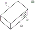
Fig. 1a shows a schematic cross-sectional side view of a device 10 according to an embodiment in a first operating state. The device 10 may be a mobile or non-mobile device, such as a mobile phone, a smart phone, a mobile computer (e.g., a tablet computer), and/or a mobile music playing means.
The apparatus 10 comprises a multi-aperture imaging device 11, the multi-aperture imaging device 11 comprising an image sensor 12, an array 14 of light channels 16 arranged adjacent to each other and a beam deflecting member 18. The beam deflecting member 18 is used to deflect the optical path 17 of the optical channel 16 and will be discussed in more detail below. The device 10 comprises a housing 22, the housing 22 comprising an outer surface 23 enclosing a housing volume 24. This means that the housing volume 24 may comprise the internal volume of the housing 22 and the volume of the housing 22. The housing volume thus also comprises the volume occupied by the housing wall and is thus enclosed by the outer surface 23 of the housing. The housing 22 may be formed to be transparent or opaque and illustratively includes a plastic material and/or a metal material. The beam deflecting member 18 comprises a first position within the housing volume 24. Holes or openings in the sides of the housing (e.g., acoustic channels for the microphone or electrical connections for the device 10) may be omitted when determining the housing volume 24. The housing 22 and/or the device arranged within the housing 22 may block the optical path 17 of the light channel 16 after being deflected by the beam deflecting member 18, such that a field of view 26 arranged outside the housing 22 to be captured by the multi-aperture imaging apparatus 11 cannot or only to a limited extent be captured. The device may be an accumulator, a plate, an opaque region of the housing 22, or the like. Expressed differently otherwise, another possible non-optical element may be arranged at the housing instead of the previous camera objective.
The housing 22 may include an aperture 28, with the housing volume 24 connected to the outer volume 25 of the housing 22 through the aperture 28. The aperture 28 may be temporarily fully or partially closed by a cover 32. The first operating state of the device 10 may be an inactive in-use operating state of the multi-aperture imaging device 11, in which the light channel 16 is deflected, for example, to the inside of the housing 22 or not.
In other words, the structural height of the arrangement of the multi-aperture imaging device is determined at least in part by the diameter of the optics (lens) of the light tunnel 16. In one (possibly optimal) case, the extension of the mirror (beam deflecting member) in the thickness direction is equal to the extension of the lens in this direction. However, the optical path of the optical channel 16 is constrained by the mirror 18. This results in a reduction in image brightness, which is dependent on the field angle. The present embodiment solves this problem by: a part or the whole of the multi-channel camera arrangement is moved so that in the operational state of the camera the arranged part protrudes beyond the housing of e.g. a smartphone compared to the state in which the camera is not used. The moving part (e.g. the beam deflecting member) may be performed in a rotational (folding), translational (extending) or hybrid manner. Similar to the zoom objective known from compact cameras, the additional movement of parts or the entire system allows a minimum configuration in the non-use mode of the camera and a larger configuration in the use mode of the camera which is optimal for the realization of the technical function.
Fig. 1b shows a schematic cross-sectional side view of the device 10 in a second operating state. In the second mode of operation, the beam deflecting member 18 comprises a second position outside the housing volume 24. This allows the beam deflecting member 18 to deflect the optical path 17 of the optical channel 16 outside the housing volume 24 and allows the field of view 26 outside the housing 22 to be capturable by the multi-aperture imaging device 11. The cover 32 may be moved out of the position shown in fig. 1a so that the beam deflecting member 18 may be moved out of the housing volume 24 through the aperture 28 of the housing 22. The beam deflecting member 18 may be moved in translation and/or rotation between the first and second positions. It is advantageous here that components in the housing 22 and/or the housing 22 do not block the deflected light path 17 of the light channel 16.
The multi-aperture imaging device 11 may be disposed within a camera housing, which in turn is disposed at least partially within the housing 22. The camera housing may for example be formed at least partly by a displacement bracket as described in connection with fig. 5. This differs from the concept in which the single-channel camera is oriented in different directions by means of a flipping mechanism in that in this case a rotation or tilting of the image sensor and/or the imaging optics can be avoided.
The full field of view may be captured by means of the apparatus 10 such that the beam deflecting member is moved from a first position to a second position in which the beam deflecting member is at least partially placed outside the housing volume. If the beam deflecting member is in the second position, the full field of view may be captured using an array of optical channels of the multi-aperture imaging device arranged adjacent to each other, the light of which is deflected by the beam deflecting member.
Fig. 2a shows a schematic cross-sectional side view of the device 20 according to another embodiment in a first operating state. The device 20 comprises a cover 23, which cover 23 is supported to be rotatable at the housing 22, for example via a connecting element 34a and/or via an optional connecting element 34 b. The connection elements 34a and/or 34b may be configured to allow tilting and thus rotational movement between the cover 23 of the beam deflecting member 18 relative to the housing 22 and be formed as hinges or roller bearings, for example.
The beam deflecting member 18 may form a cover of the housing or may be part thereof. One of the beam deflecting surfaces of the beam deflecting member 18 may be an outer edge of the housing. The beam deflecting member 18 comprises a first position and partially or completely closes the housing 22. The beam deflecting member 18 may for example comprise a reflective area for deflecting the light path 17 and may comprise a contact area for making mechanical contact with the housing 22 in the first position. In a simple way, the camera is invisible or almost invisible when not in use.
Fig. 2b shows a schematic cross-sectional side view of the device 20 in a second operating state. In the second operating state, the beam deflecting member 18 may be moved in a rotational manner (deployed) relative to the housing 22 in order to open the housing volume 24. The rotational tilting allows a tilted or inclined orientation of the beam deflecting member 18 with respect to the course of the optical path 17 of the optical channel 16 between the image sensor 12 and the beam deflecting member 18, so that the optical path 17 is deflected at the beam deflecting member 18 to a first direction 19 a.
Fig. 2c shows a schematic cross-sectional side view of the device 20 in a third position. The device 20 may exhibit a second operational state. Compared to the second position as shown in fig. 2b, the beam deflecting member 18 may deflect the optical path 17 of the optical channel 16 to another direction 19b, so that another field of view or a field of view located at a different position may be captured. This may be, for example, the light path 17 being deflected to a first side and an opposite side of the apparatus 20 and/or the user, such as a front side and a back side, a left side and a right side, or a top and a bottom. For example, the connection elements 34a and 34b may be connected to the frame structure and the beam deflecting member 18, so that the beam deflecting member 18 may alternately comprise the second or third position. The previous solution using two cameras with viewing directions towards the front and back can be replaced by a single structure, especially in smart phones, by means of switchable viewing directions of the multi-aperture imaging device.
Fig. 3a shows a schematic cross-sectional side view of a device 30 according to another embodiment in a first operating state. In contrast to the device 20 as described in fig. 2a-c, the device 30 comprises an at least partially transparent cover 36 arranged between the outer edge 23 of the housing 22 and the multi-aperture imaging device 11. An at least partially transparent cover is connected to the beam deflecting member 18 and is adapted to move based on the movement of the beam deflecting member 18. For example, the at least partially transparent cover 36 may include a polymer and/or glass material.
In other words, means may be provided which allow the encapsulation of the optical device for preventing contamination, while still possibly changing the volume of the encapsulation (movable cover glass), among other things.
Fig. 3b shows a schematic cross-sectional side view of the device 30 in a second operating state. In contrast to the device 20 in fig. 2b, the at least partially transparent cover is at least partially moved out of the housing volume 24. This may be done by a rotational movement of the beam deflecting member around the connecting element 34. The beam deflecting member 18 is used to deflect the light path 17 of the light tunnel 16 so that the light tunnel passes through the at least partially transparent cover. This 36 serves to reduce or prevent particles, dust and/or moisture from entering the housing volume 24. Thus, the cover 36 may be formed to be transparent to the light path 17 and/or implemented to be partially opaque. Illustratively, the cover 36 may be opaque to a particular range of wavelengths of electromagnetic radiation. The use of the cover 36 is advantageous in that due to the reduced amount of particles, dust and/or moisture, a long working time of the device and/or a long lasting high image quality can be obtained, due to the low contamination of the optics of the light tunnel.
Fig. 3c shows a schematic cross-sectional side view of the device 30, wherein the beam-deflecting member 18 is movable in translation by an optional actuator 38 along a direction y perpendicular to the direction x of the optical path 17 between the image sensor 12 and the light channel 16 and perpendicular to a direction z perpendicular to the line extension direction of the array of light channels 16. The beam deflecting member 18 may also be moved in a translational manner based on a rotational movement about the connecting element 34, e.g. using a guide, a rod, etc. The folding (rotational movement) may occur manually or using an actuator. An optional actuator 38 may be arranged at the beam deflecting member 18. Alternatively, the actuator 38 may be arranged between the housing 22 and the beam deflecting member 18. The actuator 38 may for example be arranged between the housing 22 and the connection element 34a and/or between the connection element 34a and the beam deflecting member 18. Here, advantageously, the shielding of the housing 22 from the field of view to be captured may be reduced by a translational movement of the beam deflection member in the x-direction of the housing.
Fig. 4a shows a schematic cross-sectional side view of the device 40 according to an embodiment in a first operating state. In the first position, the beam deflecting member 18 is arranged within the housing volume of the housing 22 and is configured to move from the first position to the second position based on a translational movement 42, as schematically shown in fig. 4 b. As shown in fig. 4a, in the first operational state, the housing may include a cover 32 or aperture therein that closes the housing 22. In the first operating state, the beam deflecting member 18 may be oriented such that it comprises a minimum extension perpendicular to the direction x defined by the optical path within the housing 22.
Fig. 4b shows a schematic cross-sectional side view of the device 40 in a second operating state. The beam deflecting member moves out of the housing volume 24 based on a translational movement 42, for example, in the x-direction. Here, the beam-deflecting member 18 may be moved through the aperture 28. The beam deflecting member 18 may be moved to be rotatable about the rotation axis 44. During the translational movement between the first and second operating states, the beam deflecting member 18 may perform a rotational movement about the rotational axis 44. The angular orientation of the beam deflecting member may be changed compared to the first operating state of fig. 4a, so that the area of the beam deflecting member used for the optical path of the multi-aperture imaging device is increased compared to the first operating state. The rotational movement 46 about the rotational axis 44 allows for a variable tilting of the beam deflecting member 18 relative to the optical path 17 between the optical channel 16 and the beam deflecting member 18 and thus allows the optical path 17 of the optical channel 16 to be deflected to a variable direction thereof. The light channel 16 may include optics 64 a-b.
In the second operating state, the optics 64a-b of the light channel 16 and/or the image sensor 12 may be arranged outside the housing volume 24, in addition to the beam deflecting member 18. Illustratively, the optics 64a-b of the light tunnel 16 and/or the image sensor 12 may move with the beam deflecting member 18, e.g., in a translational manner. This allows a small to minimal distance between the optics 64a-b of the light channel and the beam deflecting member 18, in particular in the second operating state. The small distance allows a small area of the beam deflecting member 18 to extend. Increasing the distance would require a larger area of beam deflecting member 18 and would require a greater distance of the light tunnel to fully deflect the light path of light tunnel 16 in order to achieve equal imaging parameters. Due to the small or minimal distance, the beam deflecting member 18 may also comprise a small area, which is advantageous in that in particular a minimal extension in the y-direction perpendicular to the x-direction in the viewing plane is achieved, and since smaller components have to be moved and by rotational movement, the thickness of the device has to be increased only slightly or not at all compared to the state without the beam deflecting member 18. The small size also has a favourable effect on the space required, for example, in the first or second operating state.
In other words, a multi-aperture camera having a linear channel arrangement includes several light channels arranged adjacent to each other and each transmitting a respective portion of a full field of view. Advantageously, the mirror is arranged in front of the imaging lens, which can be used for beam deflection and contributes to a reduction of the structural height. In combination with mirrors adapted to each channel (e.g. faceted mirrors, where the facets may be curved in a planar or any manner or provided with free-form surfaces), it is also possible in an advantageous manner to have substantially the same arrangement of the imaging optics of the light channels, while the viewing direction of the channels is predetermined by the individual facets of the mirror array. The surface of the beam-deflecting member is mirrored at least at the reflective facets associated with the light channels. It is also possible to have different configurations of the imaging optics of the channels so that different viewing directions result from the angles of the mirror facets and the design of the respective light channels. It is also possible to have several channels using the same area of the beam deflecting member and thus to have the number of facets smaller than the number of channels. The deflection mirror can be rotatably supported in this case, wherein the axis of rotation is, for example, parallel to the direction of extension of the channel. The deflection mirrors may be reflective on both sides, wherein a metal or dielectric layer (sequence) may be employed. The turning mirror can be performed in an analog or bistable or multistable manner. Based on the rotational movement, the beam deflecting member may be moved between at least a first position and a second position, wherein the optical paths are deflected to mutually different directions in each position. Similarly, the beam deflecting member may also be movable about the axis of rotation, as discussed for the positioning of the beam deflecting member 18 in fig. 2 a-c. In addition to the translational movement of the housing cover 32 and the beam deflecting member 18, part or all of the additional components of the multi-aperture imaging apparatus may also be moved in the same direction in a translational manner, wherein equal or different displacement paths are possible.
Fig. 5a shows a schematic sectional side view of the device 50, wherein the cover 32 is arranged at the housing side 22b of the housing 22 to be movable in a rotational manner via the moving element 34. The beam deflecting member 18 may be mechanically connected to the displacement support 47. The displacement support 47 may be understood as a mechanical transport means for moving at least the beam deflecting member 18. The device 50 may comprise an actuator for moving the displacement support 47 in a translational manner. The actuator may comprise any drive, such as a stepper motor, a piezoelectric drive or a voice coil drive. Alternatively or in addition to the actuator 33, the device 50 may comprise an actuator 33' for releasing a mechanical lock 35 locking the cover 32 and the housing to the at least one housing side 22 a. The beam deflecting member or displacement bracket 47 may be displaceable from the housing by means of a spring force, for example, when releasing the lock 33'. This means that the lock 35 may be used to hold the beam deflecting member 18 in the first position. A displacement bracket 47 may also be arranged in the device 40. This means that the displacement bracket 47 can also take up a translational movement of the cover 32.
Fig. 5b shows a schematic cross-sectional side view of the device 50, wherein the displacement support 47 is moved in the translational direction of the movement 42 so that the beam deflecting member 18 moves out of the housing volume 24. The image sensor 12 and/or the optics of the light channel 16 may also be mechanically connected to the displacement support 47 and may be movable to the same extent as the beam deflecting member 18. Alternatively, the image sensor 12 and/or optics of the light channel 16 may be movable to a lesser extent than the beam deflecting member 18 so that when moved out, the distance between the image sensor 12, optics and/or beam deflecting member 18 increases. Alternatively or additionally, the image sensor 12 and/or the optics of the light channel may be arranged at a fixed position relative to the housing, so that only the beam deflecting member 18 is moved by means of the displacement support 47. When removed, the increased distance between the image sensor 12, the optics, and/or the beam deflecting member 18 allows for a small distance of components in the first operating state so that the multi-aperture imaging device can be housed in a housing 22 that requires a small space requirement.
Fig. 5c shows a schematic cross-sectional side view of the device 50 in a second operating state. The beam deflecting member may be rotatably supported to perform a rotational movement 46 as described for the apparatus 40. As described in connection with fig. 4b, the angular orientation of the beam deflecting member 18 may be altered compared to the first operating state of fig. 5a or the state of fig. 5b, so that the area of the beam deflecting unit used by the optical path of the multi-aperture imaging device is increased compared to the first operating state. The side of the beam-deflecting member 18 facing the light channel 16 or the image sensor 12 may exhibit a dimension B (e.g. in the y-direction) perpendicular to the direction of translation of the movement 42. Dimension B is greater than dimension a of image sensor 12 or light channel 16 along this direction. The dimension B is for example perpendicular to the line extension direction of the array and parallel to the surface of the image sensor onto which the light channels impinge. The result of this may be that a high degree of light is deflectable by the beam deflecting member 18 and the brightness of the captured image is high. In the orientation shown in fig. 5a, the extension or dimension B is smaller than in the orientation shown in fig. 5c or in an orientation in which the beam deflecting member 18 directs the light path to a different viewing direction.
Fig. 6a shows a schematic cross-sectional side view of the device 60 according to an embodiment in a first operating state. The beam deflecting member 18 comprises a first position. In contrast to the device 40 and the device as described in fig. 4a and 4b, the device 50 comprises at least partially transparent covers 36a and 36b connected to the cover 32 and movable with respect to the cover 32 along the translation direction of the movement 42. At least partially transparent covers 36a and 36b may be arranged on mutually different sides of the beam deflecting member 18, between the beam deflecting member 18 and the housing 22, respectively. In the first operating state, the covers 36a and 36b may be arranged partially or fully within the housing volume 24. The covers 36a and 36b may for example be arranged at the displacement bracket 47 shown in fig. 5a-c or may be transparent areas of the displacement bracket 47.
Fig. 6b shows a schematic cross-sectional side view of the device 60 in which the beam-deflecting member 18 comprises an intermediate position between the first position and the second position. For example, the intermediate position of the beam deflecting member may be obtained when retracting the beam deflecting member 18 into the housing volume 24 or extending from the housing volume 24, respectively. The beam deflecting member 18 is partially moved out of the housing volume 24.
Fig. 6c shows a schematic cross-sectional side view of the apparatus 60 in which the beam deflecting member 18 comprises the second position (i.e. the beam deflecting member 18 is e.g. completely moved out of the housing volume 24). The at least partially transparent covers 36a and 36b comprise a mutual distance 48 which is smaller than the comparable distance between the side areas 22a and 22b of the housing.
Fig. 6d shows a schematic cross-sectional side view of the device 60 in which the distance of the at least partially transparent covers 36a and 36b is increased compared to fig. 6 a-c. The at least partially transparent covers 36a and/or 36b may be movable in a translational direction (e.g., in the positive or negative y-direction) away from the movements 52a and 52b of the respective other at least partially transparent covers 36a and 36 b. The state of the at least partially transparent covers 36a and 36b shown in fig. 6a-c may be understood as a retracted or collapsed state. The state shown in fig. 6d may be understood as an extended or unfolded state, wherein the distance 48' between the at least partially transparent covers 36a and 36b is changed (e.g. increased) compared to the distance 48. The distance 48' may be, for example, greater than or equal to the distance between comparable sides of the housing 22. The beam deflecting member 18 is used to deflect the light path of the light tunnel so that it passes through the at least partially transparent cover 36a and/or 36 b. As described in connection with fig. 4b, 5a and 5b, the angular orientation of the beam deflecting member 18 may be changed compared to the first operating state of fig. 6a or the state in fig. 6b or 6c, so that the area of the beam deflecting unit used by the optical path of the multi-aperture imaging device is increased compared to the first operating state. The increased distance 48' may alternatively or additionally allow for an increased degree of rotational movement 46. Using the rotational movement 46, the beam deflecting member 18 may be switchable between at least a first and a further position, wherein each position may be associated with a viewing direction of the multi-aperture imaging device. The rotating mirror can be performed in an analog or bistable or multistable manner. The rotational movement 46 for changing the viewing direction of the multi-aperture imaging device may be combined with the rotational movement of the beam deflecting member 18 for optical image stabilization, which is described in connection with fig. 12. The covers 36a and/or 36b may enclose other components of the multi-aperture imaging device.
The covers 36a and/or 36b or transparent regions thereof arranged opposite may comprise switchable apertures, so that the switchable apertures may for example be introduced above and/or below or in any other direction of the beam deflecting member. The aperture can be switched according to the operating state and the viewing direction of the camera. For example, the unused viewing direction of the multi-aperture imaging device may be at least partially closed by an aperture to reduce the amount of incoming stray light. For example, the aperture may be mechanically moved or may be electrochromic. The area affected by the aperture may additionally be equipped with a switchable aperture, which covers the optical structure if not being used. The aperture may be electrically controllable and comprise an electrochromic layer (sequence). The aperture may comprise a mechanically moving part. The movement may be generated using pneumatic, hydraulic, piezoelectric actuators, DC electrodes, stepper motors, thermal actuators, electrostatic actuators, electrostrictive and/or magnetostrictive actuators or drives. In one state of the multi-aperture imaging apparatus in which the viewing direction penetrates the aperture, the aperture may be switched to transmit the optical path of the optical channel. This means that the multi-aperture imaging device may comprise a first operating state and a second operating state. The beam deflecting member may deflect the light path of the light channel in the first operating state such that the light path passes through the first transparent region of the cover 36 a. In the second operating state, the light path of the light channel may be deflected such that the light path passes through the second transparent region of the cover 36 b. The first aperture 53a may be used to at least partially optically close the first transparent area in the second operational state. The second aperture 53b may be used to optically close the second transparent area at least partially or in the middle of the first operating state. Accordingly, stray light entering from a direction other than the current viewing direction of the multi-aperture imaging device can be reduced, which has a favorable effect on image quality. The first and/or second apertures 53a-b may be effective for at least one, for at least two or for all light channels. Illustratively, at least one, at least two, or all of the light channels of the multi-aperture imaging device may pass through the first aperture when the light path of the light channel is directed through the first transparent region and pass through the second aperture when the light path of the light channel is directed through the second transparent region.
It should be noted that the mechanism for unfolding the beam deflecting member according to fig. 2 and 3 may be combined with the mechanism for translational movement, i.e. there may be a mixture thereof. Unfolding the housing and/or extending the beam deflecting member may occur so that the imaging module (i.e. the light channel, its optics and/or the image sensor) may be moved out of the housing volume. The angular variation of the beam deflecting member may allow the extension of the multi-aperture imaging device to be large in the thickness direction and/or allow the beam deflecting member to deflect the optical path to the "front" and "back" in an unimpeded manner. The cover glass (e.g., cover 36) may also be fixed relative to the deployed or extended elements. The cover glass may include any planar or non-planar area.
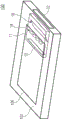
Fig. 7 shows a schematic perspective view of a device 70 according to an embodiment comprising three multi-aperture imaging devices 11 a-c. The multi-aperture imaging devices 11a-c may be movable in a translational manner along respective translational directions of the movements 42 a-c. The multi-aperture imaging devices 11a-c may be disposed in the secondary sides 22c-f of the housing 22. The housing may be formed flat, which means that the first extension of the housing 22 in the first housing direction or x-direction and the second extension of the housing 22 in the second housing direction (e.g. z-direction) may comprise at least three times, at least five times or at least seven times the dimension compared to the third extension of the housing 22 in the third housing direction (e.g. y-direction). The major sides 22a and/or 22b of the housing 22 may include first and second dimensions and may illustratively be arranged parallel to an x/z plane in space. The minor side surfaces 22c-f may be connected to or disposed between the major side surfaces 22a and 22 b.
The multi-aperture imaging devices 11a and 11b may be arranged in the housing 22 or at the same side 22d in the housing 22 and may for example comprise a mutual basic distance BA, for example for stereo purposes. More than two modules will also be conceivable. Thus, the full field of view may be captured stereoscopically or higher, for example, by using the multi-aperture imaging device 11c and at least one other multi-aperture imaging device 11a and/or 11 b. The multi-aperture imaging devices 11a, 11b and/or 11c may be individually movable. Alternatively, two or more modules may also be movable together as an entire system.
As will be described in more detail below, the apparatus 70 may be used to at least stereoscopically capture a full field of view. The full field of view may be arranged, for example, at one of the major sides 22a or 22b, but may also be arranged at the minor sides 22 c-f. The multi-aperture imaging devices 11a-c may, for example, each capture a full field of view. Although the multi-aperture imaging devices 11a-c are shown as being arranged spaced apart from each other in space, the multi-aperture imaging devices 11a, 11b and/or 11c may also be arranged spatially adjacent or arranged in combination. The array of imaging means 11a, 11b, which may for example be formed as a single line, may be arranged adjacent to each other or parallel to each other as for example described in connection with fig. 13 b. The arrays may form lines between each other, with each multi-aperture imaging device 11a and 11b comprising a single line array. The imaging devices 11a and 11b may comprise a common support for optics sharing a beam deflecting member and/or light channel and/or a common image sensor.
Fig. 8 shows an enlarged perspective view of a portion of the device 70 and the multi-aperture imaging devices 11a and 11 b. The device 70 has a second operational state. Illustratively, the multi-aperture imaging device 11a and/or 11b protrudes beyond the original housing side. The beam deflecting members 18a and 18b are moved at least partially outside the housing volume based on the direction of translation of the movements 42a and 42 b. Alternatively, in the second operating state, only portions of the beam deflecting members of the multi-aperture imaging devices 11a-c may be moved out of the housing volume of the housing 22.
The multi-aperture imaging devices 11a-b illustratively each include four light channels 16a-d and four light channels 16 e-h. Beam deflecting members 18a and 18b are each used to deflect the optical paths 17a-d and 17e-h of optical channels 16a-d and 17e-h, respectively. As will be described in more detail below, other multi-aperture imaging devices may include mutually different numbers of light channels. The multi-aperture imaging devices 11a-b may include equal or different numbers of light channels from each other.
The multi-aperture imaging devices 11a and 11b each include an illumination member 54a and 54b and 54c and 54d, respectively. The illumination members 54a-d are for at least partially illuminating the full field of view to be captured and may for example each be for illuminating the center (target area) of the full field of view to be captured. According to an embodiment, at least one of the illumination members 54a or 54b and 54c or 54d may be arranged such that it illuminates the full field of view along the average viewing direction of the light channels 16a-d and 16 e-h. The full field of view may include mutually different local fields of view each captured by at least one optical channel 16a-d and 16 e-h. The average viewing direction of the light channels 16a-d or 16e-h may for example be the geometric average of the viewing directions or the median of the viewing directions.
The illumination members 54a-b and 54c-d may be operated as flash lights of the respective multi-aperture imaging device 11a or 11b and include any light source. Advantageously, the light sources may be implemented as Light Emitting Diodes (LEDs), for example, since these exhibit a small space requirement and a low energy consumption. According to other embodiments, the multi-aperture imaging device may not include, include one or more than two illuminating members 54a-d, wherein the number of illuminating members 54a-d of the multi-aperture imaging device may be different from other multi-aperture imaging devices of the device, or may be equal. At least one of the illumination members 54a-d may be used to illuminate several target areas. Exemplarily, the light may optionally be emitted by the illumination member in one or several directions. The illuminating member may emit light in at least two viewing directions of the multi-aperture imaging device. Here, the illumination member may include at least two light sources. The light sources may emit light at opposite sides of the device. One light source each may for example be applied on the top or bottom side, the front and back side and/or the left and right side of the displacement support 47, wherein only the respective light source of that side corresponding to the selected orientation and thus the operating state of the beam deflecting member 18 and opposite to the target area to be captured in the direction of light emission is used. The above-mentioned front, back, top and bottom sides and the terms left or right are only used for illustrative purposes and are not to be construed as limiting, since they are interchangeable in connection with the respective orientation in space. This means that the light sources 54i may for example be arranged on the front and back side of the displacement support 47b and use corresponding light sources depending on the positioning of the beam deflecting member 18 b. The other, opposing light source may remain unused.
The illumination members 54a and 54b are arranged, for example, between the beam deflecting member 18a and the image sensor 12a of the multi-aperture imaging device 11 a. The beam deflecting member 18 may be used to deflect the illumination radiation emitted by the illumination members 54a and/or 54b (e.g., flash lamps). The illumination members 54a-b may be arranged in the housing volume in a first and a second operating state of the device 70. The illumination radiation may be at least partly part of the light path 17 a-d. As shown for the multi-aperture imaging device 11b, for example, the illumination members 54c and/or 54d may be arranged laterally adjacent to the beam deflecting member at the displacement support 47 b. The illumination members 54c and 54d may be moved into the housing 22 or out of the housing 22 using the translation movement 42 b. Although the illuminating member has been described in connection with the device 70, other devices or multi-aperture imaging devices described herein may also include the illuminating member.
The illumination members 54c and 54d may be mechanically connected to the displacement bracket 47a and arranged within the volume 24 in the first operating state, and thus arranged to be invisible to the user. The illumination members 54a and 54b may alternatively or additionally be arranged stationary in the housing 22. Moving the displacement bracket 47b may cause movement of the illumination members 54c and 54 d.
The optics 16a-d or 16e-f and possibly the image sensor 12a or 12b may be moved out of the housing volume together with the beam deflecting members 18a and 18b, respectively, by moving the displacement supports 47a and 47 b.
In other words, the LEDs may be applied to the movable part for enabling additional illumination (flash). The LEDs may be arranged so that they radiate in the average direction of the channel or the beam deflecting member may maintain other areas for deflecting radiation.
Fig. 9 shows a schematic perspective view of a device 90 according to an embodiment comprising a second operating state. The beam deflecting member 18 may be connected to the multi-aperture imaging device by means of mounting elements 56a and 56 b. The mounting elements 56a and 56b may be part of a displacement bracket.
Fig. 10a shows a schematic perspective view of the device 100 according to an embodiment in a first operating state. The cover 32 may form a plane with the housing major side and/or the housing minor side (e.g., housing minor side 22 c). There may be no gap, or only a small gap (e.g., less than or equal to 1mm, less than or equal to 0.5.mm, or less than or equal to 0.1mm) between the cover 32 and the housing side 22c so that the transition between the cover 32 and the housing side 22c may be imperceptible or difficult to perceive. In a simple manner, the cover 32 may not be visible.
Fig. 10b shows a schematic view of the device 100 in a second operating state. The beam deflecting member 18 comprises a second position outside the housing volume. The extended multi-aperture imaging device may be surrounded by a stationary housing frame on all sides and/or have the appearance of a button, as viewed from the outside. The device 100 may for example be configured to release a mechanical lock using mechanical pressure on the cover 32 according to fig. 10a, so that the beam deflecting member may be moved out of the housing 22, for example based on spring force. For example, the mechanical pressure may be generated by an actuator and/or a user, such as the pressure of a finger. From the second position, the beam-deflecting member can be moved again to the first position by means of an actuator or by means of mechanical pressure, and the lock is opened there. The actuator may for example be the actuator 33 or 33'. In other words, the movement can also be performed manually, so that the user extends or retracts or folds or unfolds part or the entire system by his or her own force. The movement may particularly be a combination of manual actuation and spring force effects. Thus, the user manually folds or pushes part or the entire system into the housing of the device (e.g., smartphone) for closing the camera, thus biasing the spring, and the locking mechanism maintains this position. When the camera is switched on, e.g. by means of suitable software on a smartphone, the switchable locking mechanism is released by a suitable controllable mechanism, such as a relay, and the spring force of the spring causes a part of or the entire system of the camera to extend or deploy. Furthermore, the cover forming part of the housing, the extendable and/or tiltable part and/or another mechanism located there can be implemented such that (finger) pressure on this cover releases the lock, part or the whole system is extended or deployed, and possibly the image capturing software on the device is turned on. The cover, which is also moved (which may form part of the housing at the minor surface), may be surrounded by a stationary housing on all sides, while still being visible from the outside, or truncating the minor surface in the overall height (in the thickness direction of the housing).
Fig. 10c shows an alternative schematic illustration of fig. 10a in which the cover 32 is formed such that a continuous gap is formed in the minor side 22c between the major sides of the housing 22. This allows only two posts to be perceptible in the housing 22, rather than the four posts shown in fig. 10 a. The extendable cover 32 and/or other covers may be formed as part of the housing 22 at one or several minor sides of the flat housing.
Subsequently, reference will be made to some possible embodiments of the multi-aperture imaging device, as may be used according to embodiments.
11a-c illustrate a multi-aperture imaging device 11 according to an embodiment of the invention. The multi-aperture imaging device 11 of fig. 11a-c comprises a single line array 14 of light channels 16a-d arranged adjacent to each other. Each optical channel 16a-d includes optics 64a-d for imaging a respective local field of view 74a-d of the full field of view 72 of the arrangement 11 onto a respective associated image sensor region 58a-d of the image sensor 12. The image sensor regions 58a-d may, for example, each be formed from a chip comprising a corresponding array of pixels, wherein the chips may be mounted on a common substrate or common plate 62 as indicated in fig. 11 a-c. Alternatively, of course, it would be possible for the image sensor regions 58a-d to each be formed by portions of a common pixel array that extends continuously over the image sensor regions 58a-d, where the common pixel array is formed, for example, on a single chip. In this case, only the pixel values of the common pixel array in the image sensor regions 58a-d are read out. Of course, different mixtures of these alternatives are also possible, e.g. one chip for two or several channels and another chip for yet different channels, etc. In the case of several chips of the image sensor 12, these are for example mounted on one or several boards, for example all together or grouped or the like.
In the embodiment of fig. 11a-c, four light channels 16a-d are arranged adjacent to each other in a single line in the line extension direction of the array 14, but the number four here is merely exemplary and may also be any other number larger than 1. In addition, the array 14 may also include other lines extending in a line extension direction.
The optical axes or paths 17a-d of the light channels 16a-d are parallel to each other between the image sensor areas 58a-d and the optics 64 a-d. Furthermore, the image sensor regions 58a-d are arranged, for example, in a common plane, as are the optical centers of the optics 64 a-d. The two planes are parallel to each other, i.e., parallel to a common plane of the image sensor regions 58 a-d. Furthermore, the optical centers of optics 64a-d coincide with the centers of image sensor regions 58a-d, in the case of being projected perpendicularly onto the plane of image sensor regions 58 a-d. In other words, in these parallel planes, optics 64a-d (on the one hand) and image sensor regions 58a-d are arranged along the line extension direction at equal repetition distances.
The image-side distance between the image sensor regions 58a-d and the respective optics 64a-d is adjusted so that the imaging to the image sensor regions 58a-d is adjusted to a desired object distance. The distance is, for example, in a region equal to or greater than the focal length of optics 64a-d, or, for example, in a range between one and two times (including both) the focal length of optics 64 a-d. The image-side distance along the optical axis 17a-d between the image sensor regions 58a-d and the optics 64a-d may also be adjustable, for example, manually by a user or automatically via an autofocus control.
Without additional measures, the local fields of view 74a-d of the optical channels 16a-d substantially completely overlap due to the parallelism of the optical paths or axes 17 a-d. The beam deflecting member 18 is provided to cover a larger full field of view 72 and to have the local fields of view 74a-d only partially overlap in space. The beam deflecting member 18 deflects the optical paths 17a-d or the optical axis with individual deviations of the channels into the full field of view direction 76. The full field of view direction 76 is for example parallel to a plane perpendicular to the line extension direction of the array 14 and parallel to the course of the optical axes 17a-d before beam deflection or in the case of no beam deflection. Illustratively, the full field of view direction 76 is derived from the optical axis 17a-d by rotating about the extension direction at an angle of >0 ° and <180 ° (e.g., between 80 and 100 °, and e.g., 90 °). The full field of view of the device 11, which corresponds to the full coverage of the partial fields of view 74a-d, is therefore not in the direction of extension connecting the image sensor 12 and the array 14 in series in the direction of the optical axes 17a-d, but is transverse to the image sensor 12 and the array 14 in the direction of the constructional height of the measuring device 11 (i.e. the transverse direction perpendicular to the line extension direction) due to the beam deflection. Additionally, the beam deflecting member 18 deflects the optical path of each optical path or each optical channel 16a-d using channel-individual deflection from the just-mentioned deflection resulting in direction 76. The beam deflecting member 18 thus comprises a reflective facet 68a-d for each channel 16 a-d. These are slightly inclined to each other. The mutual inclination of the facets 68a-d is chosen such that the local fields of view 74a-d are provided with a slight divergence when deflected by the beam deflecting member 18, so that the local fields of view 74a-d only partially overlap. Thus, as exemplarily indicated in fig. 11a, the respective deflections may also be such that the local fields of view 74a-d two-dimensionally cover the full field of view 72, i.e. are arranged to be two-dimensionally distributed in the full field of view 72.
It should be noted that many of the details described for the apparatus 11 are merely exemplary in choice. This is true for example for the number of optical channels mentioned earlier. The beam deflecting member 18 may also be formed differently than as presently described. For example, the beam deflecting member 18 does not have to be reflective. It may also be implemented differently than a faceted mirror, for example in the form of a transparent prism wedge. In this case, the average beam deflection may be, for example, 0 °, i.e. the direction 76 may be, for example, parallel to the optical paths 17a-d before or without any beam deflection, or in other words, the device 11 may still "look straight ahead" despite the presence of the beam deflecting member 18. The individual deflection of the channels of the beam-deflecting member 18 will again result in the local fields of view 74a-d only slightly overlapping each other, e.g. in pairs having an overlap of < 10% with respect to the solid angle area of the local fields of view 74 a-d.
Furthermore, the optical paths or axes may deviate from the parallelism described, and nevertheless, the parallelism of the optical paths of the optical channels may still be apparent, so that the local fields of view covered by the respective channels 16a-N or imaged to the respective image sensor regions 58a-d will overlap greatly without other measures (such as beam deflection), so that, in order to cover a larger full field of view by the multi-aperture imaging device 11, the beam deflecting member 18 provides optical paths with additional divergence so that the local fields of view of the N optical channels 16a-N overlap each other to a lesser extent. The beam deflecting member 18 is illustratively for a full field of view to exhibit an aperture angle that is greater than 1.5 times the aperture angle of each of the local fields of view of the optical channels 16 a-N. Using a kind of pre-divergence of the light paths 17a-d, it would also be possible that not all facets are chamfered, e.g. different, but some groups of channels comprise equally inclined facets. The latter may be formed integrally or continuously varying to each other, i.e. as one facet associated with the set of channels adjacent in the line extension direction. The divergence of the optical axes of the channels may then result from the divergence of these optical axes, as obtained by the lateral offset between the image sensor area of the channels and the optical center of the optics, or a prismatic structure or an eccentric lens portion. The pre-divergence may for example be limited to one plane. For example, before and/or without beam deflection, the optical axes may be in a common plane, but in a diverging manner, and the facets cause only additional divergence in other transverse planes, i.e. they are all parallel to the line extension direction and are inclined between each other in a different manner only to the common plane of the aforementioned optical axes, wherein again several facets exhibit the same inclination or are associated together to a group of channels whose optical axes are pairwise different, for example already in the common plane of the aforementioned optical axes before or without beam deflection.
When the beam deflecting member is omitted or implemented as a plane mirror or the like, the overall divergence can be obtained by a lateral offset between the optical center of the optical device on the one hand and the center of the image sensor area on the other hand or by a prism structure or an eccentric lens portion.
The pre-divergence that may be present and is mentioned before may for example be achieved by the optical centre of the optics lying on a straight line along the line extension direction, while the centre of the image sensor area is arranged to deviate from the projection of the optical centre along the normal of the plane of the image sensor area to a point on the straight line in the image sensor plane, for example at a point that deviates from the point on the straight line in the aforementioned image sensor plane in a channel-individual manner along the line extension direction and/or in a direction perpendicular to the extension direction and the image sensor normal. Alternatively, the pre-divergence may be obtained in such a way that the center of the image sensor lies on a straight line along the line extension direction, while the center of the optical device is arranged offset from the optical center of the image sensor along the projection of the normal of the plane of the optical center of the optical device to a point on the straight line in the optical center plane, for example at a point which is offset from the point on the straight line in the optical center plane in a channel-individual manner along the line extension direction and/or in a direction perpendicular to the line extension direction and the normal of the optical center plane. It is preferred that the aforementioned individual deviations of the channels of the respective projections only exist in the direction of the line extension, i.e. that only the optical axes lying in a common plane are provided with pre-divergence. The optical centre and the centre of the image sensor area then each lie on a straight line parallel to the line extension direction, but with a different distance between them. In contrast, a lateral offset between the lens and the image sensor in a lateral direction perpendicular to the line extension direction causes an increase in the structure height. A purely coplanar offset in the direction of the extension of the lines does not change the structure height, but the result may be that fewer facets and/or facets comprise only angularly oriented inclinations, making the arrangement simpler.
This is exemplarily illustrated in fig. 11d and 11e for the case of an optical device held on a common support, wherein the adjacent channels 16a and 16b on the one hand and the adjacent channels 16c and 16d on the other hand comprise optical axes 17a and 17b and 17c and 17d lying in the same plane, inclined with respect to each other (i.e. provided with pre-divergence). The facets 68a and 68b may be formed by facets and the facets 68c and 68d may be formed by another facet, as indicated by the dashed lines between the respective pairs of facets, with only two facets being slanted in only one direction and both being parallel to the line extension direction. It is also possible that the individual facets comprise only a tilt in the spatial direction.
Additionally, some light channels may be provided to be associated to the same local field of view, e.g. for the purpose of super resolution or for increasing the resolution used by the channels to scan the corresponding local field of view. For example, the optical channels in such a group are parallel before the beam deflection and will be faceted to the local field of view. Preferably, the pixel images of the image sensors of a channel of a group are located at intermediate positions between the pixel images of the image sensors of another channel of the group.
Instead of for super-resolution purposes but only for stereo purposes, implementations will for example also be conceivable in which one set of directly adjacent channels in the line extension direction completely covers the full field of view with their partial field of view, and the other set of directly adjacent channels in turn completely covers the full field of view and the optical paths of the two channel sets pass through the substrate or support 66. This means that the multi-aperture imaging device may comprise a first plurality of light channels for possibly fully capturing the full field of view. The second plurality of optical channels of the multi-aperture imaging device may be used to capture the full field of view as well, and possibly completely. Thus, the full field of view may be captured at least stereoscopically by the first plurality of optical channels and by the second plurality of optical channels. The first plurality of light channels and the second plurality of light channels may impinge on a common image sensor, be deflected using a common array (array optics) and/or by a common beam deflection member. In contrast to an array formed by individual cameras, it is advantageous to form a continuous array camera which as a whole is controllable as a device (e.g. with respect to focusing and/or image stabilization), since all channels are affected simultaneously and using the same actuator. Furthermore, the advantages result from the monolithic arrangement with regard to the mechanical stability of the overall arrangement (in particular with temperature variations). This is advantageous for synthesizing a full image from the sub-images of the individual channels and when used in a stereo, triple, quadruple, etc. system when three-dimensional object data is obtained when the full field of view is scanned multiple times by different multiple channels 16.
The following discussion relates to optics 64a-d whose lens planes are also parallel to the common plane of image sensor regions 58 a-d. As will be described below, the lenses of the optics 64a-d of the light channels 16a-d are mounted to the major side 66a of the substrate 66 using one or several lens holders and mechanically connected to each other using the substrate 66. In particular, the optical paths 17a-d of the plurality of optical channels 16a-d pass through the substrate 66. The base plate 66 is thus at least partially formed of a transparent material and has the shape of a plate or, for example, of a parallelepiped or another convex body having a planar main side 66a and, opposite thereto, a also planar main side 66 b. The major side is preferably positioned perpendicular to the light path 17-d. As will be described below, according to embodiments, there may be deviations from the true hexahedral shape that may result from a lens implemented as an optical device integrated with a substrate.
In the embodiment of fig. 11a-c, the flat support substrate 66 is for example a substrate made of glass or polymer. Illustratively, the support substrate 66 may comprise a glass plate. The material of substrate 66 may be selected for high optical transparency and low temperature coefficient or other mechanical properties such as hardness, elastic modulus or poisson's ratio.
The substrate 66 may be implemented as a simple planar portion of the optical path without any additional lenses directly accommodated thereon. Additionally, an aperture (e.g., an aperture or stray light aperture) and/or a filter layer (e.g., an IR-blocking filter) may be applied on the substrate surface, or may comprise a different substrate of several layers on which the aperture and filter layers may be applied, which in turn may be different for each channel, e.g., in spectral absorption.
The substrate 66 may comprise a material having different properties (particularly non-constant absorption) in different regions of the electromagnetic spectrum that may be detected by the image sensor.
In the embodiment of fig. 11a-c, each optic 64a-d includes three lenses. However, the number of lenses may be selected as desired. The number may be one, two or any other number. The lens may be convex, comprising only an optical imaging function region (e.g. spherical, aspherical, free-form region) or two regions (e.g. two mutually opposing regions), to result in e.g. a convex and a concave lens shape. Several optically effective lens areas are also possible, for example by forming the lens from several materials.
In the embodiment of fig. 11a-c, a first lens 78a-d of each light channel 16a-d or optic is formed on the major side 66 a. For example, the lenses 78a-d have been fabricated by molding on the major side 66a of the substrate 66 and are made of, for example, a polymer (e.g., a UV curable polymer). The molding is done, for example, by a molding tool and curing can be done, for example, using temperature and/or UV irradiation.
In the embodiment of fig. 11a-c, each optic 64a-d includes additional second and third lenses 82a-d and 84a-d, respectively. The lenses are fixed relative to each other within the respective lens holder, illustratively by means of axial tubular lens holders 86a-d, and to the lens holder at the primary side 66, for example by means of gluing or another bonding technique. The apertures 88a-d of the lens holders 86a-d are provided, for example, with circular cross-sections in the cylindrical inner walls of which the lenses 82a-d and 84a-d are mounted. Thus, for each optic 64a-d, the lens is coaxially located on a respective optical axis of the optical path 17 a-d. The lens holders 86a-d may also include a profile that varies over its length or along the respective optical axis. Here, the profile may exhibit increasing rectangular or square characteristics with decreasing distance from the image sensor 12. The outer shape of the lens holder may thus also differ from the shape of the aperture. The material of the lens holder may be light absorbing. The lens holder may also be implemented non-rotationally symmetric and/or non-coaxial corresponding to the tilted optics described above in connection with fig. 11d and 11 e.
Mounting using the aforementioned lens holder illustratively occurs so that the lens apexes of the lenses supported by these are spaced from the base plate 66.
As already mentioned above, the substrate 66 may be planar on both sides and therefore not exhibit a refractive power effect. However, the substrate 66 may also include mechanical structures (e.g., recesses or protrusions) that allow for simple positive and/or non-positive orientation of components such as connecting individual lenses or housing portions. In the embodiment of fig. 11a-c, on the major side 66b, the base plate 66 may, for example, include a structure that makes mounting or orientation simpler at the location of the respective end of the tube of the lens holder 86a-d on which the respective optics 64a-d is mounted. These structures may be, for example, circular recesses or differently shaped recesses into which the sides of the respective lens holders 84a-d may engage, corresponding to the shape of the sides of the respective lens holders facing the substrate. It should be pointed out again that different aperture profiles and thus correspondingly lens apertures which may differ from a circular aperture are possible.
Thus, the embodiment of FIGS. 11a-c preserves the classic structure of a camera module that includes a respective lens and includes a transparent housing support that completely surrounds the respective lens for holding it. While the above-described embodiment uses a transparent body 66 as the substrate support. Which extends over several adjacent light channels 16a-d so as not to be penetrated by the imaging light path of the light channels. It does not interfere with imaging nor increase the structural height.
However, various possibilities are indicated how the embodiment of fig. 11a-c may be varied. Illustratively, the substrate 66 need not extend over all of the channels 66a-d of the multi-aperture imaging device 11. In contrast to what has been described previously, each optic 64a-d may include a lens held on both sides 66a and 66b via a lens support, as shown in FIG. 11 f.
The presence of only lenses 82e-h on the major side 66a, i.e. no lenses 82a-d and/or 84a-d on the other side 66b, is also possible, since the lenses 82a-d and/or 84a-d are provided on the other side 66a (i.e. the side facing away from the substrate 66 of the image sensor 12, but not the side facing the image sensor 12, i.e. 66 a). Further, the number of lenses in the lens supports 86a-d may be selected as desired. Thus, there may be only one lens or more than two lenses may be provided in such supports 86 a-h. As shown in fig. 11f, the lenses may be mounted to both sides 66a and 66b via respective lens supports 86a-d and 86e-h on respective sides 66a and 66b, respectively.
Fig. 12 exemplarily shows that the multi-aperture imaging device of fig. 11a-c can be supplemented by one or several of the additional members described below.
Fig. 12 exemplarily shows that there may be a member 91 for turning the beam deflecting member 18 around a rotation axis 44 parallel to the line extension direction of the array 14. The axis of rotation 44 lies, for example, in the plane of the optical paths 17a-d or is spaced apart from it by less than one quarter of the diameter of the optics 64 a-d. Alternatively, the axis of rotation can, for example, of course also be less than the diameter of the optical component or less than four optical component diameters apart. For example, the member 92 may be provided to rotate the beam deflecting member 18 only within a small angular range (e.g., within less than 1 ° or less than 10 ° or less than 20 ° of span) with a short response time to compensate for, for example, shaking of the multi-aperture imaging device 11 by a user while taking a picture. In this case, the member 92 will be driven by the image stabilization controller, for example.
Alternatively or additionally, the member 92 may be used to vary the full field of view defined by the full coverage of the partial fields of view 74a-d (FIG. 11a) with a large angular offset in its direction. Thus, the deflection may be achieved by rotating the beam deflection member 18, wherein the full field of view is arranged in opposite directions with respect to the device 11, for example by implementing the beam deflection member 18 as a mirror array that is reflective on both sides.
Alternatively or additionally, the apparatus 11 may comprise means 94 for moving the optics 64a-d by means of the substrate 66 or for moving the substrate 66 itself and thus the optics 64a-d in a translational manner in the direction of the line extension. The member 94 may for example also be driven by the aforementioned image stabilization controller to achieve image stabilization transverse to that achieved by rotating the mirror deflection arrangement 18 by a movement 96 in the line extension direction.
Alternatively or additionally, the apparatus 11 may include means 98 for varying the image-side distance between the image sensor 12 and the optics 64a-d or between the image sensor 12 and the support 66 to effect depth of field adjustment. Member 98 may be driven by a manual user control or an autofocus control or a focusing member of device 11.
The members 94 thus serve to suspend the base plate 66 and are preferably arranged laterally adjacent to the base plate 66 along the line extension direction as indicated in fig. 12, so as not to increase the structural height. The following is also true for members 92 and 98: which is preferably arranged in the plane of the light path so as not to increase the structural height. Member 98 may also be connected to beam deflecting member 18 and move beam deflecting member 18 simultaneously or approximately simultaneously so that the distance between optics 64a-d and beam deflecting member 18 remains substantially constant or remains constant as the image-side distance between image sensor 12 and optics 64a-d is changed. Members 94, 92, and/or 98 may be implemented based on pneumatic, hydraulic, piezoelectric actuators, DC motors, stepper motors, thermal actuators, electrostatic actuators, electrostrictive and/or magnetostrictive actuators or drives.
It is pointed out that the optical devices 64a-d may be held in a constant relative position with respect to each other, for example not only using the aforementioned transparent substrates, but also with respect to the beam deflecting member, for example using a suitable frame, which preferably does not increase the structural height and thus preferably lies in the plane of the components 12, 14 and 18 or in the plane of the optical path. The stability of the relative position may be limited to the distance along the optical axis between the optics and the beam deflecting member, such that the member 98 may move the optics 64a-d in conjunction with the beam deflecting member, for example, in a translational manner along the optical axis. The distance of the optics to the beam deflecting member may also be set to a minimum distance so that the optical path of the channel is not laterally limited by the portion of the beam deflecting member 18, thereby reducing the construction height, since the portions 68a-d would otherwise have to be dimensioned with respect to the lateral extension for the largest distance of the optics to the beam deflecting member so as not to intersect the optical path. Additionally, the aforementioned stability of the relative position of the frame may rigidly hold the optics and beam deflecting member relative to each other along the x-axis so that the member 94 moves the optics 64a-d and beam deflecting member in a translational manner along the linear extension direction.
The beam deflecting member 18 for deflecting the optical path of the optical channel described above, in combination with the actuator 92 for generating the rotational movement of the beam deflecting member 18 of the optical image stabilization controller of the multi-aperture imaging apparatus 11, allows stabilization of the image or the full field of view in two dimensions, i.e. image stabilization along a first image axis substantially parallel to the line extension direction by the translational movement of the substrate 66 and image stabilization along a second image axis substantially parallel to the optical axis before or without beam deflection or perpendicular to the optical axis and the line extension direction when considering the deflected optical axis, by generating the rotational movement of the beam deflecting member 18. Furthermore, the described arrangement may cause translational movement of the array 14 and the beam deflecting member fixed in the mentioned frame perpendicular to the line extension direction, for example by the described actuator 98 which may be used to effect focus adjustment and thus an autofocus function.
Translational relative movement between the image sensor 12 and the array 14 may be implemented alternatively or in addition to rotational movement for achieving image stabilization along the second image axis. This relative movement may be provided, for example, by member 94 and/or member 98.
For completeness' sake, it is also noted with respect to the above discussion that when taking a picture, the apparatus captures one image of the scene per channel across the image sensor area (which has been imaged onto the image sensor area by the channel), and the apparatus may optionally include a processor which combines or fuses the images to form a full image corresponding to the scene in full field of view and/or provides additional data such as 3D image data and depth information for the subject scene used to generate the depth map, as well as for software implementations such as refocusing (the area in which sharpness is determined after the actual image capture), all in focus images, a virtual green screen therein (separation of foreground and background), and so on. The latter tasks may also be performed by any processor or externally. However, the processor may also be a component external to the multi-aperture imaging device.
Fig. 13a shows that the aforementioned alternative device 11 can be mounted, for example, in a flat housing of a portable device 130, such as a mobile telephone, a smartphone or a media player, in which case the plane of the image sensor 12 or of the image sensor region and the lens plane of the optics of the light channel 16 are oriented perpendicular to the flat direction of extension of the flat housing or parallel to the thickness direction. In this way, the beam deflecting member 18 positions the full field of view, for example providing the multi-aperture imaging device 11, in front of the front side 12 of the flat housing, which also comprises, for example, a screen. Alternatively, such a deflection would also be possible: the field of view is located in front of the back side of the flat housing opposite the front side 12. The housing 22 of the device 130 or the device itself can be flat, since the overall height of the device 11 parallel to the thickness of the housing can be kept small by the illustrated position of the device 11 in the housing. Switchability may also be provided by providing a window on the side opposite to the side 102 and for example by moving the beam deflecting member between two positions, for example when the beam deflecting member is implemented as a mirror that is specularly reflective on both the front side and the back side and is turned from one position to the other, or as a faceted mirror having one set of facets for one position and another set of facets for the other position, wherein the sets of facets are adjacent to each other in the direction of line extension, and switching between the positions takes place by moving the beam deflecting member back and forth in the direction of line extension in a translatory manner. It will of course also be possible to mount the apparatus 11 in another device, such as a car, which may not be portable.
It should still be mentioned that in alternative embodiments comparable to the embodiments described above, the beam deflecting member may also be absent. When only parts of the local fields of view need to overlap each other, this may be achieved, for example, by a mutual lateral offset between the center of the image sensor area and the optical center of the optics of the corresponding channel. Nevertheless, the actuator according to fig. 12 may be applied, wherein, as an alternative to the member 92, the actuator 94 may, for example, additionally be capable of performing a translational movement of the optics or the support 66.
In other words, the above embodiments show a multi-aperture imaging device having a single line array of light channels arranged adjacent to each other, wherein a substrate made of glass or polymer, for example, for enhanced stability, extending over the channels is located at any desired position in the optical path of the multi-aperture imaging device. The substrate may additionally comprise lenses on the front and/or back side. The lens may be made of the material of the substrate (e.g. formed by hot embossing) or molded thereon. There may also be other lenses in front and behind the substrate that are not located on the substrate and are mounted separately. There may be several substrates in the arrangement along and perpendicular to the line extension direction. It is thus also possible to connect several substrates in series with the lens along the light path, i.e. to additionally hold them in a predetermined positional relationship one after the other, for example using a frame (without joining). In this way twice as many main sides of the used support substrate will be available for providing or mounting lenses, e.g. a substrate 66 which may be provided with lenses according to the above example (here exemplarily according to fig. 11b) and a substrate which may also be provided with lenses according to the above example, i.e. a substrate in which there are lenses mounted to the main sides 66a and/or 66b via lens holders, however this is here exemplarily shown to be manufactured integrally, e.g. by injection moulding or the like, so that the lenses are formed on the sides 66a and 66b, wherein of course a moulded lens of other material than the material of the parallelepiped substrate 66 will be possible, such as a lens on only one of the sides 66a and 66 b. Both substrates are transparent and are penetrated by the light path through the major sides 66a and 66 b. The above-described embodiments may thus be implemented in the form of a multi-aperture imaging device having a single line channel arrangement, where each channel transmits a partial field of view of the full field of view and the partial fields of view partially overlap. Arrangements of several such multi-aperture imaging devices for stereo, triple, quadruple, etc. arrangements are possible for 3D image capture. Thus, the plurality of modules may be implemented as a continuous line. Successive lines may use the same actuator and a common beam-deflecting element. One or several mechanically enhanced substrates may be present in the light path, may extend over the entire line, which may form a stereo, triple, quadruple arrangement. A super-resolution approach can be employed in which several optical channels image the same local field of view. The optical axis may already diverge without the beam deflecting member, so that fewer facets are required on the beam deflecting unit. In this case, the facet advantageously comprises only a single angular component. The image sensor may comprise only one slice, only a continuous matrix of pixels or several interrupted matrices of pixels. The image sensor may be provided by a number of partial sensors arranged adjacent to each other, for example on a printed circuit board. The autofocus drive of the focusing member may be implemented such that the beam deflecting element moves synchronously with the optics, or is stationary. Embodiments provide for the optical path between the image sensor 12 and the beam deflecting member 18 to be substantially or completely parallel when there is no pre-divergence.
Fig. 13b shows a schematic setup comprising a first multi-aperture imaging device 11a and a second multi-aperture imaging device 11b, which may be arranged in the device 130, for example. The two multi-aperture imaging devices 11a and 11b may form a common multi-aperture imaging device 11 and include a common image sensor 12 and/or a common array 14. The single- wire arrays 14a and 14b illustratively form common wires in the common array 14. The image sensors 12a and 12b may form a common image sensor 12 and may, for example, be mounted on a common substrate or a common circuit support (e.g., a common board or a common flex board). Alternatively, the image sensors 12a and 12b may also include substrates different from each other. Different hybrids of these alternatives are of course possible, such as multi-aperture imaging devices comprising a common image sensor, a common array and/or a common beam-deflecting member 18, and other multi-aperture imaging devices comprising separate components. An advantage of having a common image sensor, a common single line array and/or a common beam deflection member is that by driving a small number of actuators it may be achieved to move the respective components with high accuracy and synchronization between the actuators may be reduced or avoided. Furthermore, high thermal stability can be achieved. Alternatively or additionally, other multi-aperture imaging devices may include a common array, a common image sensor, and/or a common beam-deflecting member. The arrangement of the multi-aperture imaging device 11 may for example be useful for capturing a full or partial field of view stereoscopically when the light channels of the different partial multi-aperture imaging devices 11a and 11b are directed onto the same partial field of view. Similarly, other multi-aperture imaging devices may be integrated into a common multi-aperture imaging device so that higher order capture is possible compared to stereo.
Fig. 14 illustrates a 3D multi-aperture imaging device 140 as may be used in accordance with embodiments described herein. Having a structure which can be divided into two parts 12 as indicated in fig. 141And 122(i.e., for the "right" optical channel 161A part 12 of1And for the "left" channel 162Another part 12 of2) The image sensor of (1). In the example of FIG. 14, the right and left light channels 161And 162Have the same settings but are laterally offset from each other by a substantial distance BA to obtain as much depth information as possible about the scene present in the field of view of the device 140. Illustratively, the 3D multi-aperture imaging device may be formed by two or more multi-aperture imaging devices 11. The element provided with the reference numeral of index 1 in the first position from the left thus belongs to the first component 1 or first module (module 1) of the device 140 for the right channel, and the element provided with the reference numeral of index 2 in the first position from the left thus belongs to the second component 2 or second module (module 2) of the device 140 for the left channel. Although the number of modules is 2 in fig. 14, the apparatus may also comprise more modules arranged at respective basic distances with respect to each other.
In the exemplary embodiment of FIG. 14In case of multiple ones each 161And 162Includes four light channels arranged adjacent to each other. The individual "right" lanes are distinguished from each other by the second subscript index. The channels are indexed from right to left. This means that the light channel 1611(not shown in fig. 14 due to the partial cross-sectional view chosen for clarity reasons) is exemplarily arranged at the rightmost edge in a basic distance direction 108 (in which direction the left and right channels are arranged offset from each other by a basic distance BA), i.e. from the plurality 162The left channel is furthest away, with the other right channels 1612To 1614Following in the base distance direction 108. Channel 1611To 1614Thus forming a light channel of the single-wire array whose wire extending direction corresponds to the basic distance direction 108. Left channel 162The same setup is shown. They are also distinguished from each other by the second subscript index. Left channel 1621To 1624Arranged adjacent to each other and following one another in the same direction, e.g. right channel 1611And 1614Also, the channels 16 are made in such a way21Closest to the right channel and channel 1624Furthest from the right channel.
In FIG. 14, the image sensor area 58 of the image sensor 1211To 5814Or a component 12 of an image sensor 121Is arranged in a plane parallel to the basic distance direction BA or to the line extension direction 108, wherein the light tunnel 1611To 1614The lens plane of the optical device of (1) is also parallel to this plane. In addition, the image sensor region 5811To 5814Arranged at a lateral interchannel distance 110 between each other, the light channels 1611To 1614Are also arranged at this distance from each other in said direction, so that the light channels 1611To 1614In the image sensor area 5811To 5814And an optical device 1611To 1614Are parallel to each other. Illustratively, the image sensor area 5811To 5814And the light channel 1611To 1614Is arranged perpendicular to the aforementioned image sensor area 5811To 5814On the respective optical axis of the common plane.
It should be noted that the optical paths or axes may also deviate from the parallelism described, but the parallelism of the optical paths of the optical channels may still be significant so as to be represented by the individual channels 1611To 1614Covered or projected onto respective image sensor areas 5811To 5814Will largely overlap without other measures (such as beam deflection) so that to cover a larger full field of view by the multi-aperture imaging device 140, the beam deflecting member 18 provides additional divergence to the optical path such that the channels 1611To 1614Overlap each other to a lesser extent. Beam deflecting member 181Exemplary providing a full field of view includes averaging aperture angles over all azimuthal angles or all transverse directions, the aperture angles being larger than the optical channel 1611To 1614Is 1.5 times larger than the corresponding average aperture angle of the local field of view.
In addition to the aforementioned components, the 3D multi-aperture imaging device includes a processor 112, the processor 112 having a right light tunnel 16 that merges into a beam that has been passed through the 3D multi-aperture imaging device 1011To 1614The task of capturing an image to form a first full image. The problems to be solved are as follows: due to the right channel 1611To 1614Between adjacent channels 110 in the image area 5811To 5814 Middle passage channel 1611To 1614The captured images cannot simply be shifted relative to each other or in a translational manner and cannot be placed one on top of the other. In other words, they cannot be simply combined. Image sensor regions 58 corresponding to each other but located in different images when capturing the same scene11To 5814This lateral offset in the direction B, 108 or 110 in the image of (a) is called disparity. The difference in the mutually corresponding image content in turn depends on the distance of said image content in the scene, i.e. the distance of the corresponding object from the device 140. Processor 112 may now attempt to evaluate image sensor region 58 itself11To 5814To merge these images with each other to form a first full image, i.e. the "right full image". Disadvantageously, however, there is an inter-channel distance 110 and therefore excitation problems, whereas on the other hand the inter-channel distance 110 is relatively small so that the depth resolution or estimation is only inaccurate. Thus, an attempt is made to determine the overlap region between the two images (for example the image sensor region 58), for example by means of a correlation11To 5814In the overlap region 114 between the images) of the image contents corresponding to each other is difficult.
Thus, the processor of FIG. 14, has a local field of view 7411And 7412In betweenThe differences in the paired images, one of which has passed through the left channel 16, are used in the overlap region 114 for merging21Or 1622A capture, left channel 1621Or 1622Of the second partial field of view (i.e. 74)21Or 7422) Overlapping with an overlap region 114. Illustratively, to merge image sensor regions 5811To 5812 Processor 112 evaluates the image (one of which has been passed by image sensor region 58)21Or 5822And the other is captured by one of the channels contributing to the overlap region 114, i.e., by the image sensor region 5811Or 5812One captured image). Such a pair would then include the base distance BA plus/minus one of the channel base distances 110 or a base distance that does not add/subtract the channel base distance 110. The subsequent base distance is much greater than the respective channel base distance 110, which is why the difference in the overlap region 86 is more easily determined by the processor 112. Thus, to merge the images of the right channels, the processor 112 evaluates the difference between the images of one of the right channels and one of the left channels, preferably not exclusively, caused by the images of the left channels.
More specifically, the processor 112 may also more or less directly from the image 5811Take over the local field of view 74 that does not overlap with any other local field of view of the right channel11And based on the image sensor area 5812To 5814To the local field of view 7412、7413And 7414Performs the same operation in the non-overlapping area of (1), in which the image sensor area 5811To 5814May have been captured simultaneously, for example. In adjacent local fields of view only (e.g. local field of view 74)11And 7412) In the overlap region, the processor 112 uses the difference from the image pair whose overlap overlaps in the overlap region in the full field of view 74, but primarily, but not exclusively, one of the image pair has been captured by one of the right channels and the other by one of the left channels (e.g., again at the same time).
However, according to an alternative procedure, the processor 112 may also warp all images of the right channel based on an evaluation of the difference between pairs of images for which a respective one image has been captured by the right channel and another image is captured by the left channel. Thus, for an image of the right channel, the full image computed by the processor 112 may, for example, not only be the local field of view 74 of the right channel11To 7414Is virtually "curved" in the overlapping region, e.g. also by the processor 85 also aligning the partial fields of view 74 which do not overlap with each other11To 7414Evaluates the differences from the image pair (where one image is captured by one of the right channels and the other image is captured by one of the left channels), is also virtually "warped" in non-overlapping regions to lie laterally to the right channel 1611To 1614On the viewpoint at the center between.
The 3D multi-aperture imaging device 140 of fig. 14 is not only capable of generating a full image from the image of the right channel, but the 3D multi-aperture imaging device 140 of fig. 14 is also capable of generating, at least in one mode of operation, a full image of the left channel in addition to the full image of the first channel from the taken picture and/or generating a depth map in addition to the full image of the right channel.
According to a first alternative, the processor 112 is for example adapted to combine the left light channel 1621To 1624Or image sensor area 5821To 5824Captured image to form a second full image (i.e., full image of the left channel) and a local field of view 74 at the left optical channel21To 7424In the overlap region of laterally adjacent local fields of view, pairs of images (primarily, but not exclusively, one of which has been passed through right light channel 16) are used11To 1614Local field of view 74 captured and paired with21To 7424Overlap and the other has been preferably captured by one of the left optical channels, the local field of view overlapping the respective overlap region).
According to a first alternative, the processor 112 outputs two full images, one of the right optical channels and the other of the left optical channels, for one picture taken. These two full images may be supplied to the eyes of the user separately, for example, and thus result in a three-dimensional impression of the captured scene.
According to another alternative mentioned previously, the processor 112 uses pairs of images (at least for the right channel 16) in addition to the full image of the right channel11To 1614Including at least one pair having an image captured by a respective right channel and another image captured by one of the left channels) to generate a depth map.
In embodiments where the depth map is generated by the processor 112, the aforementioned warping may also be performed on all images captured by the right channel based on the depth map. Since the depth map includes depth information across the full field of view 72, the entire image captured by the right channel (not only in its overlapping region but also in the non-overlapping region) can be curved to a virtual common aperture point or virtual optical center.
Two alternatives may also be processed by the processor 112: first, two full images can be generated, i.e. as already described, one full image of the right light channel and the other full image of the left light channel, by using the difference from the pair of images, one of which belongs to the image of the left channel, when merging the images of the right channel in the overlapping area between the images of the right channel, and by using the difference from the pair of images, one of which belongs to the image of the right channel, so that a full image comprising a matching depth map is then generated from the full image of the scene in the full field of view representing the different perspectives obtained in this way, such as a full image located between (but possibly not exclusively on) the optical centers of the optics of the right and left optical channels relative to a virtual vision or virtual optical center. To compute the depth map and to warp one of the two full images or to warp and merge the two full images into virtual vision, the processor 85 then uses the right and left full images, so to speak as intermediate results from the previous merging of the left and right individual images. Thus, the processor here evaluates the difference in the two intermediate resulting full images to obtain a depth map and performs a warping or warping/merging thereof.
It should be mentioned that the processor 112 evaluates the differences in the pairs of images by means of, for example, cross-correlation of image regions.
It should be mentioned that more than four pass-bands may also be covered with each other (whether they belong to the left or right channel) by a different coverage of the full field of view 72 of the partial field of view of the left channel on the one hand and the right channel on the other hand, for example also in case of mutual overlap between overlapping regions with the partial fields of view (adjacent in the line direction or column direction) of the above examples, wherein the partial fields of view of the right channel and the partial fields of view of the left channel are each arranged in columns and rows. Generally applied to the number of difference sources, N defines the number of local fields of view having mutual overlap.
In addition to the above description, it should be mentioned that the processor 112 may optionally also perform per-channel correction of perspective imaging errors of the respective channels.
It should be noted that the embodiment of fig. 14 is merely exemplary in many respects. This applies, for example, to the number of optical channels. Illustratively, the number of right optical channels is not 4, but is greater than 2 or any number between 2 and 10 (including 2 and 10), and when considered for each local field of view or each channel paired with a respective local field of view with maximum overlap, for all of these pairs, the overlap region of the local field of view of the right optical channel may be within the image region 5811To 5814Between 1/2 and 1/1000 of the average image size of the captured image (e.g., measured in the image plane, i.e., the plane of the image sensor area). For example, the same applies to the left channel. However, the number of right and left channels may be different. This means that the number of left optical channels NLAnd the number of right optical channels NRIt is not necessary to be equal and the partial field of view of the full field of view 72 divided into the left channel and the partial field of view divided into the right channel do not have to be approximately equal as in the case of fig. 14. Regarding the local field of view and its overlap, if 10m images are consideredThe distance or object distance, at least for all pairs with the largest overlap, the local fields of view may stand out from each other by, for example, at least 20 pixels, wherein this may apply to the right and left channels.
In contrast to what has been discussed above, it is additionally not required that the left and right channels are formed as a single line. The left and/or right channels may also form a two-dimensional array of light channels. Furthermore, the single-wire array does not necessarily have to comprise collinear wire extension directions. However, the arrangement of fig. 14 is advantageous in that it results in a minimum structural height perpendicular to the plane in which the optical axis of the light channel (i.e. both the right and left channels) is directed before or without beam deflection. As regards the image sensor 12, it has already been mentioned that it may be formed by one, two or several chips. Illustratively, there is a per image sensor area 5811To 5814And 5821To 5824One chip is provided, wherein in case of several chips these chips may be mounted on one or several boards, e.g. one board for the left channel or the image sensor of the left channel and one board for the image sensor of the right channel.
In the embodiment of fig. 14, it is also possible to place adjacent channels as densely as possible within the channel of the right or left channel, wherein the channel distance 110 corresponds in the optimum case to the lens diameter. The result here is a small channel distance and therefore a low difference. The right channel on the one hand and the left channel on the other hand may be arranged at an arbitrary distance BA with respect to each other, so that a large difference may be achieved. In summary, artifact-reduced or artifact-free image fusion and depth map formation using passive optical image systems becomes possible.
In contrast to the above embodiments, more than two sets of channels 16 are used1And 162It would be possible. The number of groups may be referred to by N. If in this case the number of channels per group is equal and the division of the full field of view into the partial field of view is equal for all groups, e.g. for each overlapping area of the partial field of view of the group 161 The source of the difference in the number of. However, different divisions of the full field of view are also possible for groups of channels, as mentioned above.
Finally, it should be noted that in the above description, only an exemplary case in which the processor 112 fuses images of the right channel has been discussed. The same process (as previously mentioned) may be performed by the processor 112 for both or all channel groups, or also for the left channel, etc.
Fig. 15a illustrates an embodiment of a multi-aperture imaging device 150. Preferably, the image sensors 58a-d are arranged in a common plane (i.e. the image plane of the light channel 16 or its optics). In fig. 15a, this plane is for example parallel to a plane spanned by the z-axis and the y-axis of a cartesian coordinate system (indicated in fig. 15 and provided with reference numeral 115 for simplicity of the following description).
With a linear array of light channels, the extension of the multi-aperture imaging device 150 along the direction of linear extension is greater than the diameter of the lens, as bounded downwardly by the image sensor 12 and optics 64. The minimum extension of the multi-aperture imaging device 150, as determined by the mutual arrangement of the image sensor 12 and the optics 64 along the z-axis (i.e. along the optical axis or optical path of the light channels 16a to d), is smaller than the minimum extension along the z-axis, but larger than the minimum extension of the multi-aperture imaging device in a transverse direction y perpendicular to the line extension direction z due to the implementation of the light channels 16a to d as a single line array. The latter is determined by the lateral extension of each individual light channel 16a to d, for example the extension of the optics 64a to d (possibly including the holder 66) along the y-axis.
As already described above, in the embodiment of fig. 15a, the optical axes 17a to d are, for example, parallel to one another, as shown in fig. 15a, or they are only slightly offset, before or without deflection by the beam deflection member 18 or at the optics 64a to d. The corresponding centering of the optical elements 64a to d and of the image sensor regions 58a to d is easy to produce and is suitable with regard to the minimization of the installation space. The parallelism of the optical paths of the light channels also causes the local fields of view covered by the individual channels 16a to d or imaged by the respective image sensor regions 58a to d to overlap approximately completely without further measures, such as beam deflection. In order to cover a larger full field of view by the multi-aperture imaging device 150, another function of the beam deflecting member 18 is to provide divergence to the optical paths so that the local fields of view of the channels 16a-d overlap each other to a lesser extent.
It is assumed that, for example before the beam deflection member 18 or without the beam deflection member 18, the optical axes 17a to d of the optical paths of the optical channels 16a to d are parallel to one another or deviate by less than a tenth of the local field of view of the optical channels 16a to d with respect to the minimum aperture angle of the parallel orientation along the orientation averaged over all channels. Without additional measures the local fields of view will largely overlap. The beam-deflecting member 18 of fig. 15a thus comprises, for each light channel 16a to d, a reflective facet 68a to d clearly associated with this channel, the reflective facets 68a to d each being optically planar and inclined with respect to each other, so that the partial fields of view of the light channels overlap to a lesser extent with respect to the solid angle and cover, for example, a full field of view comprising an aperture angle, the aperture angle being, for example, greater than 1.5 times the aperture angle of the respective partial field of view of the light channels 16a to d. In the exemplary case of fig. 15a, the mutual inclination of the reflective facets 68a to d provides, for example, light channels 16a to d which are arranged substantially linearly adjacent to each other along the z-axis to cover the full field of view 72 according to the two-dimensional arrangement of the local fields of view 74a to d.
When considering in the embodiment of fig. 15a the angular deflection of the optical axes 17a to d of the light channels 16a to d in a plane spanned by the average direction of the optical axes before and after deflection of the light beams on the one hand (i.e. in the zy-plane in the example of fig. 15a) and on the other hand in a plane perpendicular to the last-mentioned plane and parallel to the average direction of the optical axes after deflection of the light beams, the example of fig. 15a corresponds to the exemplary case in which the average direction after deflection of the light beams corresponds to the y-axis. On average, the optical path of the light channel is deflected by 90 ° about the z-axis in the yz plane, and the optical axis is on average not tilted from the yz plane.
For example, refers to the inclination of
 facet 68a relative to the xz plane measured in the xy planeOblique angle, i.e. the inclination of the face 68a about the z-axis relative to the xz-plane in which the optical axes 17a-d lie. Corresponding to the orientation of
 facet 68a parallel to the xz-plane. Therefore, application of Accordingly, the number of the first and second electrodes,
 defining the inclination of the
 facet 68a measured along the z-axis with respect to the plane including the xz-plane And the angle of inclination of the plane parallel to the z direction. Accordingly, the following applies:
 the same definition applies to the other channels:
 for each light channel, the set angle may be greater than the angle of inclination of the reflective facet associated with that channel relative to the angle of the support substrate through which the light channel passes. Here, the support substrate may be positioned parallel to a line extending direction of the
 array 14, and the setting angle may be in a plane perpendicular to the line extending direction.
Fig. 15b to 15e show side views of a beam deflecting member according to an embodiment for exemplary four light channels arranged linearly or in a single line. The beam deflecting members of fig. 15b to 15e may be used as the beam deflecting means of fig. 11a, wherein, however, in this case, the partial field of view does not cover the full field of view in a clockwise direction 3, 4, 2, 1 (as shown in fig. 11a) but in the order of 4, 2, 1, 3 in a clockwise direction. The inclination angles of the facets 68a to d are shown in fig. 15b to e. They are distinguished from each other by subscript indices 1 through 4 and are associated with respective channels. Is at an angle of 0 DEG,
 the same is true. The backside of the support substrate, i.e. the side opposite to the surface provided with the
 facets 68a to d, is indicated by 121 in fig. 15b to 15 e. The material forming the parallelepiped-shaped portion of the support base plate 123 is located below the imaginary line 125. It can be seen that the added additional material comprises a small volume, making the moulding easy.
The support substrate 123 is placed at a set angle with respect to the image sensor 12 Tilt, i.e. the axis on which the average direction of deflection around the optical axis of the light channel is based, i.e. the z-axis in fig. 15 a. This setting angle provides the surface of the beam deflection means 18 facing the
 image sensor 12, so that a "rough deflection" of the light path of the light channel has been caused.
For the deflection angle of the optical path of each light channel deflected by the beam deflection means 18, this means that these are each based on a setting angle And based on the respective inclination of the reflective facets associated with the light channels with respect to the
 support substrate 123. The individual inclinations of the facets mentioned 68a-d are, as just described, described by the inclination angle in the xy-plane and the inclination angle in the plane perpendicular to the support substrate 123 relative to the normal to the support substrate 123. Preferably, when for each corner, a corner is provided Greater than the inclination, i.e. for all channels,
 when is paired with
 Or even
 Even more preferred when said inequality has been satisfied. In other words, it is preferred that the setting angle is so large compared to the inclination angle of the
 facets 68a-d that there is less additional material compared to a pure parallelepiped shaped beam deflecting member. May for example be between 30 ° and 60 ° (including 30 ° and 60 °).
The fabrication of the beam deflecting device 18 of fig. 15b-e may be done, for example, by molding additional material onto the support substrate 123 by a molding tool. The support substrate 123 may here be, for example, glass, while the additional material of the mold thereon is a polymer. Another possibility for the beam deflection means 18 of fig. 15b-e would be to be integrally formed by injection moulding or the like. The result here is that the surface of the beam deflecting member facing the image sensor is mirrored at least at the reflecting facet associated with the light channel. The support substrate may be supported to be rotatably rotatable as described for example in connection with fig. 4 b.
For example, some aspects of the settings of the multi-aperture imaging devices described so far relate to desired or instantaneous adjustments prior to or at the time of capturing a full image. The multi-aperture imaging device 150 of fig. 15a includes a processor, such as, for example, processor 112, that combines images captured by the image sensors 58a-d, e.g., simultaneously with the aforementioned adjustments, to form a full image representing the scene in the full field of view 72. The algorithm used by the processor 112 for merging or fusing the images projected onto the image sensor regions 58a-d by the light channels 16a-d and already captured by the image sensor regions 58a-d to form a full image is, for example, designed such that assumptions that certain parameters of the devices of the multi-aperture imaging apparatus 150 described above are met are maintained in order to meet certain preconditions for the quality of the full image or to make the algorithm fully applicable. Illustratively, the algorithm assumes that one or several of the following assumptions hold:
1) the distance of the optics to the image sensor area along the x-axis is equal for all light channels 16 a-d;
2) the relative positions of the local fields of view 74a-d, and in particular the overlap between the local fields of view 74a-d, correspond to a predetermined default value or deviate from the latter by less than a predetermined maximum deviation.
However, for different reasons, one or several of the just mentioned hypotheses may not be maintained or not sufficiently maintained. The reason for not being maintained may be, for example, not to maintain manufacturing variations, such as inaccuracies in the relative positions of the optical devices 64a-d with respect to each other and with respect to the image sensor 12. Manufacturing inaccuracies may also include inaccuracies in mounting the mirror deflection means 18 and may include inaccuracies in the relative positions of the facets 68a-d with respect to each other when the beam deflection means 18 comprises the facets 68 a-d. Additionally or as an alternative to manufacturing-induced tolerances, temperature variations may cause one or several of the aforementioned assumptions to be inapplicable or insufficiently maintained.
To the extent that the algorithm executed by the processor 112 for merging or fusing the images of the image sensor regions 58a-d to form a full image can compensate for deviations from the optimal orientation and arrangement of the components, such as deviations from a set cluster of the positions of the local fields of view 74a-d within the full field of view 72 and the relative positions of the local fields of view with respect to each other. When merging or fusing images, the processor 112 may compensate for such deviations, for example, to some extent. However, when a certain deviation limit is exceeded (hypothesis 2 is not maintained), the processor 112 will, for example, not be able to compensate for the deviation.
The multi-aperture imaging device 150 is manufactured, for example, to maintain the just-mentioned assumptions throughout a temperature range, however, the manufacturing costs of the multi-aperture imaging device 150 tend to increase. To avoid this, the multi-aperture imaging device 150 of fig. 15a comprises an adjustment member 116 for channel-individually changing the relative position between the image sensor region 58i of the respective light channel 16i, the optics 64i of the respective light channel 16i and its beam deflection means 18 or corresponding portion 68i, or for channel-individually changing the optical properties 16i or the optical properties of the portion 68i of the beam deflection means 18 associated with deflecting the light path of the respective light channel. The adjustment member 116 is driven by and performs adjustment tasks according to the default values. These are provided by the memory 118 and/or the controller 122, as will be discussed below.
The apparatus 150 illustratively includes a memory 118 having stored default values for channels to individually drive the adjustment members 116. The default values may be predetermined by the manufacturer and stored in the memory 118. Additionally, the processor 112 may be capable of refining or updating the stored default values in the memory 118 using an evaluation of the captured images of the image sensor regions 58a-d (e.g., images that are merged or fused by the processor 112 to form a full image), for example, as indicated by the dashed line 124 in FIG. 15 a. Illustratively, the processor 112 captures a scene by adjusting the multi-aperture imaging device 150 with the currently stored default values using the adjustment means 116, as will be described in more detail below. Thus, the default values are read from the memory 118 and used by the adjustment component 116 for channel-individual adjustment. By analyzing the images of the image sensor regions 58a-d captured in this manner, the processor 112 obtains information about how the default values stored in the memory 118, which are used only for capture, are modified to result in the above-described assumptions being more accurately or in an improved manner maintained when later taking pictures using these improved or updated default values.
The stored default values may include a complete set of adjustment values, i.e., a set of adjustment values for completely adjusting the device 150. They are selected as described above and as discussed further below to reduce or remove certain individual channel deviations of the optical properties of the channels from the set properties.
The default values may comprise several sets of adjustment values, e.g. one set for each sequence of consecutive temperature intervals, so that at all times that set of adjustment values will be used for image capturing appropriate for the current situation. Thus, the controller 122 may, for example, perform a table that accesses or looks up correlations between sets of default values and different preset conditions in the memory 118. For the access, the controller 122 obtains sensor data reflecting the current situation, such as data relating to temperature, pressure, humidity, position of the device 150 in the space, and/or instantaneous acceleration or instantaneous rotational speed of the device 150, and determines from these data one of several sets of default values in the memory 118, i.e. the one associated with the closest preset situation to the current situation described by the sensor data. The sensor data may also have been obtained from image sensor data of the image sensor area. Illustratively, a set of the respective temperature intervals in which the current temperature is located is selected by the controller 122. The default values for the group selected from memory 118 used by adjustment means 116 for a particular image capture may then be updated again when optional feedback 124 is used.
The stored default values may for example be configured such that a discrete measurement of the distribution of one or several characteristics in the light channel is reduced by driving the adjusting means by means of the stored default values, i.e. the lateral deviation of the local field of view from the regular distribution of the local field of view, the focal length of the optics or the depth of field distance of the light channel.
Alternatively, the default values in the controller 122 may be determined without using the memory 118, for example, when the mapping of current sensor data to suitable default values is fixedly integrated in the controller 122. The mapping may be described by a functional relationship between the sensor data and a default value. The functional relationship may also be modifiable by a parameter. The parameters may be modified by means of feedback 124.
The memory 118 may be, for example, a non-volatile memory. It may for example be a read-only memory, but a rewritable memory is also possible. The controller 122 and the processor 112 may be implemented in software, hardware, or programmable hardware. Which may be programs executing on a common microprocessor. The sensor used to provide sensor data to the controller 122 may belong to the device 150, such as an image sensor area, or an external component, such as a component of the equipment in which the device is installed, as will be discussed below with reference to the following figures.
Possible implementations of the adjustment member 116 will be described below. The adjusting means 116 of fig. 15a can be applied here to one, several or all of the implementation variants described below. Specific combinations will also be discussed below.
In the variant shown, the adjustment member 116 illustratively comprises an actuator 126i for each channel 16i, the actuator 126i moving the optics 64i of the corresponding channel 16i transversely thereto in an axial direction along the optical axis 17i or along the optical path and/or along the z-axis and/or the y-axis. Alternatively, the actuator 126i may, for example, also move the image sensor 12 or the respective image sensor region 58 i. In general, the actuator 126i may cause relative movement of the image sensor region 58i, the optics 64i, and/or the corresponding portion 64i of the beam deflecting member 24.
According to a variant related to fig. 16a, the adjusting means 116 comprises for each channel 16i a phase-changing optical element or phase-changing element 128i, which as indicated in fig. 16a may be integrated into the respective optical device 64ai (128i "), into the portion 68i (128 i" "), positioned between the image sensor region 58i and the optical device 64i (128') or between the optical device 64i and the beam deflecting member portion 68i (128 i"'), wherein combinations of the aforementioned possibilities are also possible. The phase-changing optical element 128i may cause a position-dependent change in the refractive index, i.e. its areal distribution, for example by a liquid crystal. Alternatively or additionally, the phase-changing optical element 128i causes a change in the shape of the optically active surface, for example when using a piezo that mechanically acts on a flexible, solid, transparent material and causes a deformation, or by using the electrowetting effect. The phase-changing element 128i' may, for example, change the refractive index of the optical device 64 i. Alternatively, the phase-changing element 128i' may change the shape of the optical lens region of the optic 64i, and thus change the effective refractive power of the optic 64 i. The phase-altering elements 128i "" may, for example, generate a sinusoidal phase grid on the optically relevant surface (e.g., on the reflective facets) of the portion 68i to cause a virtual tilt of the corresponding surface. Similarly, the phase-changing element 128i' or the phase-changing element 128i ″ may deflect the optical path.
In other words, the phase change caused by the phase-changing optical element 128i may be largely rotationally symmetric, e.g. about the optical axis 17i, and thus cause a change in the focal length of the optical device 64i, e.g. in the case of 128i ″. However, the phase change caused by the element 128i may also be largely linear, for example along the z-axis or along the y-axis, to cause a change in the deflection angle or the deflection of the optical axis 17i in the corresponding direction.
Rotationally symmetric phase changes may be used for focusing, just as linear phase changes may be used to correct the position of the local field of view corresponding to optical channel 16 i.
According to another variant, illustrated in fig. 16, the adjustment member 116 comprises, for each channel 16i, an angular orientation (i.e. setting angle) thereof with respect to the optical axis 17i ) An actuator 132i that alters the portion 68i (e.g., the reflective facet of the respective channel 16 i). It should be mentioned here that the portion 68i is not limited to reflective facets. Each section 68i may also be implemented as a prism deflecting the direction of the optical axis 17i in the yz plane, while the optical path of the optical channel 16i passes through the prism.
Pneumatic, hydraulic, piezoelectric, thermal, electrostatic or electric drives or DC or stepper motors or voice coil drives may for example be used to effect relative movement by the actuators 126i and 132i, i.e. to generate movement (e.g. in a translational manner) of the optics 68i and to tilt the portion 68i by the actuator 132i and the z-axis.
Turning to fig. 15a, the dashed lines indicate that the multi-aperture imaging apparatus 150, in addition to the adjustment member 1116, may include one or several actuators 134 for producing channel global relative movement between the image sensor 12, the optics array 14 and the beam deflecting member 18 that is equal for all of the optical channels 16 a-d. Thus, as indicated in fig. 15a, the one or several additional actuators 134 may be part of an optional autofocus controller 136 (focusing member) and/or an optional image stabilization controller of the multi-aperture imaging device.
A specific example of the device 150 of fig. 15a supplemented by an additional actuator is shown in fig. 17. FIG. 17 shows the multi-aperture imaging device 150 of FIG. 15a, wherein the optics 64a-d of the light channels 16a-d are mechanically secured to each other via a common support 66. Using a common support, optics 64a-d may be subjected to global movement equal to all channels, for example, by translational movement of support 66 in the z-direction (i.e., along the line extension of array 14). Here, an actuator 134a is provided. The actuator 134a thus produces a translational movement of the optics 64a-d, which translational movement of the optics 64a-d is equal for all light channels 16a-d by the actuator 134a causing the common support 66 to undergo a translational movement along the z-axis. As to the type of actuator 134a, reference is made to the example mentioned with reference to fig. 16a and 16 b. Furthermore, the apparatus 150 comprises an actuator 134b for a channel global change of the distance between the image sensor 58i and the optical device 64i along the z-axis or along the optical axis 17i, which is equal for all light channels 16 a-d. As indicated in FIG. 17, actuator 134b does not cause optics 64a-d to undergo translational movement along the z-axis for changing the distance from the associated image sensor portion 58a-d using support 66 and using actuator 134a, actuator 134a thus also undergoes translational movement along the x-axis and thus serves as a suspension for support 66.
Furthermore, the apparatus 150 of FIG. 17 comprises an actuator 134c for rotating the beam deflecting member 18 about an axis parallel to z or lying in or not remote from the plane in which the optical axes 17a-d lie. As regards the actuators 134b and 134c, reference is made to the list of examples previously provided with reference to fig. 16a and 16b, with regard to possible implementation examples. The rotational movement applied to the beam deflecting member 18 by the actuator 134c has the same effect on the portions 68a-d of the beam deflecting member 18 for all channels 16a-d, i.e. is channel global.
Using the actuator 134b, the autofocus controller 136 can, for example, control the captured focus of the device 150 by way of the channels 16a-d in a channel-global sense. The image stabilization controller 138 can stabilize the full field of view 72 from the user's shake, for example, by means of the actuator 134c in a first direction 142 and by means of the actuator 134a in a direction 144 perpendicular to the first direction 142. The first direction 142 may result from a rotational movement about the rotational axis 44. Alternatively or additionally, a translational movement of the beam deflecting member 18 and/or the array 14 may be generated by the actuator 134, as indicated by the first direction 142'. The directions 142, 142', and 144 may thus be parallel to the image axis, in the plane of the directions, or correspond thereto. The image stabilizer described herein may be implemented to have a common effect on two, more, or all of the optical paths of the optical channel. This means that the image stabilization of the channel alone can be omitted, which is advantageous.
Illustratively, the apparatus 150 of FIG. 15a includes an actuator for each channel 16a-d, such as actuator 126i for each channel 16i, for example, to cause the image sensor regions 58a-d to undergo translational movement along the z-axis and/or along the y-axis in a channel-individual manner, for example, in order to compensate for manufacturing inaccuracies or temperature-induced drift of the local field of view within the full field of view. The apparatus 150 of FIG. 15a may alternatively or additionally include an actuator 128i' to compensate for the undesirable differences in focal length of the optics 64a-d caused by manufacturing. Additionally or alternatively, the apparatus 150 of fig. 15a may include an actuator 128i' "to compensate for deviations in the relative tilt of the portions 68a-d between each other caused by manufacturing or due to temperature, so that the relative tilt causes the desired coverage of the full field of view 72 through the local fields of view 74 a-d. Additionally or alternatively, the device 150 may ultimately include actuators of the 128i 'and/or 128i' "type.
In summary, the apparatus 150 may comprise an actuator 134c for rotating the beam deflecting member 18 about an axis parallel to the line extension direction z of the array 14. The axis of rotation lies, for example, in the plane of the optical axes 17a-d or is spaced therefrom by less than one quarter of the diameter of the optics 68 a-d. Alternatively, the axis of rotation can of course also be further away, for example with less than the optics diameter or less than four optics diameters. For example, the actuator 134c may be provided to rotate the beam deflecting member 18 only within a small angular range (e.g., within a span of less than 5 ° or less than 10 °) with a short response time to compensate for shaking of the multi-aperture imaging device 150 caused by the user, for example, when taking a picture. In this case, the actuator 134c will be driven by the image stabilization controller 138, for example.
Alternatively or additionally, the actuator 134c may be used to change the full field of view 72 (fig. 15a) defined by the full coverage of the partial fields of view 74a-d in its direction with a larger angular adjustment. Thus, deflection may also be achieved by rotating the beam deflecting member 18, wherein the full field of view is arranged in opposite directions with respect to the device 150 by, for example, implementing the beam deflecting member 18 as a mirror array reflecting on both sides.
Alternatively or additionally, the apparatus 150 may comprise an actuator 134a for moving the optics 64a-d by means of the substrate 66 or moving the substrate 66 itself and thus the optics 64a-d in a translational manner in the direction of the line extension. The actuator 134a may also be driven, for example by the aforementioned image stabilization controller, to achieve image stabilization transverse to that achieved by the movement 96 in the line extension direction, which is achieved by rotating the mirror deflection arrangement 18.
Further, the apparatus 150 may additionally or alternatively include an actuator 134b for changing the image-side distance between the image sensor 12 and the optics 64a-d or between the image sensor 12 and the body 66 to achieve adjustment of the depth of field (compare fig. 12). Member 98 may be actuated by manual user control or by autofocus control of device 150.
The actuator 134a also serves to suspend the substrate 66 and, as indicated in fig. 15a, is preferably disposed laterally adjacent the substrate 66 along the line extension direction so as not to increase the structural height. It also applies to the actuators 134b and 134c, the actuators 134b and 134c preferably being arranged in the plane of the optical path so as not to increase the structural height.
It should be noted that the optical devices 64a-d may be held in a constant relative position with respect to each other, not only for example via the transparent substrates already mentioned, but also with respect to the beam deflecting member, for example using a suitable frame, which preferably does not increase the structural height and thus preferably lies in the plane of the components 12, 14 and 66 or in the plane of the optical path. The stability of the relative position may be limited to the distance between the optics and the beam deflecting member along the optical axis, such that the actuator 134b illustratively moves the optics 64a-d and the beam deflecting member 18 together along the optical axis in a translational manner. The distance of the optics to the beam deflecting member can be adjusted to a minimum distance so that the optical path of the channel is not laterally limited by the portion of the beam deflecting member 18, thereby reducing the construction height, since the portion 68i would otherwise have to have a lateral extension with respect to the maximum optics to beam deflecting member distance dimensioned so as not to interrupt the optical path. Additionally, the stability of the relative position may mean that the aforementioned frame holds the optics and the beam deflecting member in a mutually rigid manner along the z-axis, so that the actuator 134a will move the optics 64a-d and the beam deflecting member together in a translational manner along the line extension direction.
In combination with the actuator 134c for generating a rotational movement of the beam deflecting member 18 and the actuator 134a of the optical image stabilization controller of the multi-aperture imaging device 150, the beam deflecting member 18 for deflecting the optical path of the optical channel described above allows image or full field stabilization in two dimensions, i.e. along a first image axis substantially parallel to the line extension direction by a translational movement of the substrate 66, and along a second image axis (substantially parallel to the optical axis before or without beam deflection, or perpendicular to the optical axis and the line extension direction when considering the deflected optical axis) by generating a rotational movement of the beam deflecting member 18. Furthermore, the arrangement described may cause translational movement of the beam deflecting member and the array 14 fixed in the mentioned frame, for example by the actuator 54 described which may be used to effect focus adjustment and thus an autofocus function.
Fig. 18 shows a schematic diagram illustrating an advantageous arrangement of actuators, such as a multi-aperture imaging device 180 for image stabilization and/or focus adjustment. The image sensor 12, array 14 and beam deflecting member 18 may span a cuboid in space. The cuboid may also be understood as a virtual cuboid and may for example comprise a minimum volume and a minimum vertical extension in particular in a direction parallel to the y-direction or thickness direction and comprise the image sensor 12, the single-wire array 14 and the beam deflection member 18. The minimum volume may also be understood as a cuboid spanned by the arrangement and/or operational movement of the image sensor 12, the array 14 and/or the beam deflecting member 18. Array 14 may include a line extension direction 146 along which light channels 16a and 16b are arranged adjacent to each other (may be parallel). The line extension direction 146 may be arranged at a fixed position in space.
The virtual cuboid may comprise two side faces oriented parallel opposite to each other, parallel to the line extension direction 146 of the single-line array 14, and parallel to portions of the optical paths 17a and/or 17b of the optical channels 16a and 16b between the image sensor 12 and the beam deflecting member 18. In a simplified manner, but without limiting effect, these may be, for example, the top and bottom sides of an imaginary cuboid. The two sides may span a first plane 148a and a second plane 148 b. This means that the two sides of the cuboid may each be part of the planes 148a and 148 b. Other components of the multi-aperture imaging apparatus may be disposed entirely, but at least partially, in the region between the planes 148a and 148b, so that the space requirements of the multi-aperture imaging apparatus 180 in a direction parallel to the surface normal of the planes 148a and/or 148b are small, which is advantageous. The volume of the multi-aperture imaging device may include a small or minimal structural space between planes 148a and 148 b. The installation space of the multi-aperture imaging device in the lateral direction for the extension direction of the planes 148a and/or 148b can be large or as large as desired. The volume of the virtual cuboid is influenced, for example, by the arrangement of the image sensor 12, the single-wire array 14 and the beam deflection member 18, wherein the arrangement of these components may, according to the embodiments described herein, be such that the structural space of these components in the direction perpendicular to the plane and thus the mutual distance between the planes 148a and 148b becomes small or minimal. The volume of the virtual cuboid and/or the distance of the other sides may be increased compared to other arrangements of components.
The multi-aperture imaging device 180 includes an actuator member 152 for producing relative movement between the image sensor 12, the single-wire array 14 and the beam deflecting member 18. The actuator member 152 is at least partially disposed between the planes 148a and 148 b. The actuator member 142 may be configured to move at least one of the image sensor 12, the single line array 14, or the beam deflecting member 18 in one or several directions in a rotational manner about at least one axis and/or in a translational manner. Here, the actuator member 152 may include at least one actuator (e.g., actuator 128i, 132i, and/or 134) for channel-individually changing the relative positions between the image sensor region 58i of the respective light channel 16i, the optics 64i of the respective light channel 16i, and the beam deflecting member 18 or its corresponding portion 68i, or for channel-individually changing the optical properties 16i or the portion 68i of the beam deflecting member 18 associated with deflecting the optical path of the respective light channel. Alternatively or additionally, the actuator member may implement autofocus and/or optical image stabilization, as already described above.
The actuator member 152 may include a dimension or extension 154 parallel to the thickness direction. A portion of up to 50%, up to 30%, or up to 10% of dimension 154 may protrude from the area between planes 148a and 148b beyond planes 184a and/or 184b, or from an area. This means that the actuator member 152 projects at most inconsequentially beyond the plane 148a and/or 148 b. According to an embodiment, the actuator member 152 does not protrude beyond the planes 148a and 148 b. It is advantageous that the extension of the multi-aperture imaging device 180 in the thickness direction is not increased by the actuator member 152.
A preferred implementation of the beam deflecting member 18 will be described with reference to fig. 19a to f. The implementations illustrate a number of advantages that can be performed individually or in any combination, but are not limiting.
Fig. 19a shows a schematic cross-sectional side view of a beam deflecting element 172 as may be used for the beam deflecting member described herein, such as the beam deflecting member 18 of fig. 4, 5 or 6. The beam-deflecting element 172 may be operative for one, more or all of the optical channels 16a to d and comprise a polygon-like sequence of profiles. Although a triangular cross-section is shown, it may exhibit any other polygonal shape. Alternatively or additionally, the profile may also comprise at least one curved surface, wherein in particular an implementation with a reflective surface, at least in parts being planar, may be advantageous to avoid imaging errors.
For example, beam-deflecting element 172 includes a first side 174a, a second side 174b, and a third side 174 c. At least two sides, such as sides 174a and 174b, are implemented to be reflective, such that beam-deflecting element 172 is implemented to be reflective on both sides. Sides 174a and 174n may be major sides of beam-deflecting element 172, i.e., sides having a larger area than side 174 c.
In other words, the beam-deflecting element 172 may be formed in a wedge shape and be reflective on both sides. Opposite area 174c, i.e., between areas 174a and 174b, there may be another area, however, much smaller than area 174 c. In other words, the wedge formed by areas 174a, b and c does not taper to a point, but is provided with an area, and is therefore flat at the sharp sides.
Fig. 19b shows a schematic cross-sectional side view of the beam-deflecting element 172 in which the suspension or displacement axis 176 of the beam-deflecting element 172 is depicted. The displacement axis 176 about which the beam deflecting element 172 can be moved in a rotational and/or translational manner in the beam deflecting member 18 can be eccentrically offset with respect to the center of mass 178 of the cross-section. The centroid may alternatively be a point that describes half the dimension of the beam-deflecting element 172 in the thickness direction 182 and in the direction 184 perpendicular thereto.
For example, the displacement axis may be constant along the thickness direction 182 and exhibit any offset in a direction perpendicular thereto. Alternatively, an offset in the thickness direction 182 is also possible. For example, a displacement may occur in order to obtain a higher actuation path with a rotation of the beam-deflecting element 172 about the displacement axis 176 than when rotating about the center of mass 178. Thus, by displacing the displacement axis 176, the path covered in rotation by the edge between the sides 174a and 174b may be increased by an equal angle of rotation as compared to rotation about the center of mass 178. Preferably, the beam-deflecting element 172 is arranged such that the edge between the sides 174a and 174b (i.e. the sharp side of the wedge-shaped cross-section) faces the image sensor. The respective other side 174a or 174b can deflect the light path of the light tunnel with a small rotational movement. It becomes clear that the rotation may be performed such that the space consumption of the beam deflecting member in the thickness direction 182 is small due to the movement of the beam deflecting element 172, so that it is not necessary that the main side is perpendicular to the image sensor.
The beam deflecting element 72 may be formed of glass, ceramic, glass-ceramic, plastic, metal, or a combination of these materials and/or other materials.
In other words, the beam deflecting element 172 may be arranged such that the tip (i.e., the edge between the major sides 174a and 174b) faces the image sensor. The holding of the beam-deflecting element can be done so that it is done only on the back side or within the beam-deflecting element, i.e. the main side is not hidden. The common retaining or connecting elements may extend on the back side 174 c. The axis of rotation of the beam deflecting element 172 may be arranged to be eccentric.
Fig. 19c shows a schematic perspective view of a multi-aperture imaging device 190 comprising an image sensor 12 and a single line array 14 of light channels 16a to d arranged adjacent to each other. The beam deflecting member 18 includes a plurality of beam deflecting elements 172a to d corresponding to the number of optical channels. Alternatively, a smaller number of beam deflecting elements may be arranged, for example when at least one beam deflecting element is used by two optical channels. Alternatively, a higher number may be arranged, for example, when the deflection direction of the beam deflecting member 18 is switched by a translational movement. Each beam deflecting element 172 a-d may be associated with a light channel 16 a-d. The beam deflecting elements 172a to d may be shown as a plurality of elements 172 according to fig. 11. Alternatively, at least two, several or all beam deflecting elements 172a to d may be integrally formed.
Fig. 19d shows a schematic cross-sectional side view of a beam-deflecting element 172 whose cross-section is formed into a free-form shape. Thus, the side 174c may comprise a recess 186 allowing the mounting of the holding element, wherein the recess 186 may also be formed as a protruding element, such as a groove of a tongue and groove system. The profile additionally includes a fourth side 174d, which fourth side 174d includes an area less than the major sides 174a and 174b and connects the major sides 174a and 174b to each other.
Fig. 19e shows a schematic cross-sectional side view of the first beam-deflecting element 172a and the second beam-deflecting element 172b behind it in the direction shown. The recesses 186a and 186b may thus be arranged such that they substantially coincide, so that it is possible to arrange the connecting elements in the recesses.
Fig. 19f shows a schematic perspective view of beam-deflecting member 18, which illustratively comprises four beam-deflecting elements 172a to d connected to a connecting element 188. The connecting element may be available so as to be movable in translation and/or rotation by the actuator. The connecting element 188 may be integrally formed and located at or within the beam deflecting elements 172 a-d in the direction of extension (e.g., y-direction in fig. 5 c). Alternatively, the connecting element 188 may also be connected to only at least one side of the beam deflecting member 18, as when the beam deflecting elements 172 a-d are integrally formed. Alternatively, the connection to the actuator and/or to the beam-deflecting elements 172a to d may take place in any other way, for example by means of gluing, twisting or welding.
Although some aspects have been described in connection with an apparatus, it should be understood that these aspects also represent a description of the corresponding method, so that blocks or elements of the apparatus are also understood as corresponding method steps or features of method steps. Analogously, aspects that have been described in connection with or as method steps also represent details or features of the corresponding block or of the corresponding apparatus.
The above-described embodiments are merely illustrative of the principles of the present invention. It is to be understood that modifications and variations of the arrangements and details described herein will be apparent to others skilled in the art. Therefore, it is intended that the invention be limited only by the scope of the following claims and not by the specific details that have been presented herein using the description and discussion of the embodiments.
Claims (68)
1. A device (10; 20; 30; 40; 50; 60; 70; 90; 100; 130) comprising a multi-aperture imaging device, comprising:
a housing (22); and
multi-aperture imaging apparatus (11; 140; 150; 180) comprising:
an array (14) of light channels (16 a-d; 16N) arranged adjacent to each other; and
a beam deflection member (18) for deflecting the optical paths (17a-d) of the optical channels (16 a-d; 16N);
wherein an outer surface (23) of the housing (22) encloses a housing volume (24) in a first operational state of the apparatus, wherein the beam deflecting member (18) comprises a first position within the housing volume (24) in the first operational state of the apparatus,
wherein the beam deflecting member (18) comprises, in a second operating state of the apparatus, a second position in which the beam deflecting member (18) is at least partially arranged outside the housing volume (24); and
wherein in a transition from the first to the second operating state the optics (64a-b) and the image sensor (12) of the light channel (16 a-d; 16N) move in a translational manner together with the beam deflecting member (18);
and at least one of:
wherein the beam deflecting member (18) is mechanically connected to a displacement support (47), the displacement support (47) being movable in a translation direction of movement (x) to move the beam deflecting member (18) between the first position and the second position;
wherein the lenses (82a-h, 84a-d) of the optics (64a-d) of the light channels (16 a-d; 16N) are mounted by one or several lens holders to a main side (66a-b) of at least one substrate (66) and are mechanically connected via the at least one substrate (66), wherein the light paths (17a-d) of a plurality of light channels (16 a-d; 16N) pass through the at least one substrate (66);
wherein the beam deflecting member (18) comprises a first location and a second location, the beam deflecting member (18) being movable between the first location and the second location, wherein the beam deflecting member (18) is adapted to deflect the light path (17a-d) of each light channel into mutually different directions (19a-b) in the first location and the second location; and wherein the beam deflecting member (18) comprises a third location in the first location, wherein the beam deflecting member (18) comprises an extension (B) in the third location, which extension (B) is perpendicular to a line extension direction (z, 146) to the array (14) and parallel to a surface of an image sensor (12) onto which the light channels (16 a-d; 16N) impinge, wherein the extension (B) is smaller in the third location than in the first and second locations;
wherein a distance (48, 48') between the at least one transparent region (36a) of the displacement support (47) and a side face (36b) of the displacement support (47) opposite to the transparent region (36a) is variable, and wherein the distance (48, 48') is smaller in the first position of the beam deflecting member (18) than in the second position of the beam deflecting member (18); wherein the beam-deflecting member (18) is formed as an array of facets (68 a-d; 68i) arranged along a line extension direction (z; 146) of the array (14) of light channels (16 a-d; 16N); wherein the deflection angle of deflecting the optical path (17a-d) of each light channel is based on the setting angle of the support substrate (123) of the beam deflection member (18) with respect to the image sensor (12) on which the light channel (16 a-d; 16N) impinges And on the basis of the inclination of a reflecting facet (68i) associated with a light channel (16i) facing the surface of the beam-deflecting member (18) of the image sensor (12) with respect to the supporting substrate (123)
 The inclination
 Varies between the optical channels (16 a-d; 16N); and
comprising an adjustment member (116) for channel-individually changing the relative position between the image sensor area (58a-d) of the respective light channel (16 a-d; 16i), the at least one optical device (64a-d) of the respective light channel and the beam deflection member (18), or for channel-individually changing the optical properties of the at least one optical device (64a-d) of the respective light channel (16 a-d; 16i) or of a portion (68 a-d; 68i) of the beam deflection member (18) associated with deflecting the light path (17a-d) of the respective light channel; and a memory (118) having stored default values for the adjustment members and/or a controller (122) for converting sensor data reflecting the current situation of the device into default values for channels individually driving the adjustment members (116).
2. The apparatus of claim 1, wherein each optical channel (16 a-d; 16N) includes optics 64a-d for imaging a respective local field of view, and a group of optical channels covers a full field of view; wherein the apparatus comprises a processor configured to merge or fuse images of the optical channels to form a full image corresponding to a scene in the full field of view.
3. The device according to claim 1, wherein a connecting element (34a, 34b) is connected to the frame structure and the beam deflecting member (18) so that the beam deflecting member (18) can alternately comprise the second position or the third position.
4. The device of claim 1, wherein different locations are arranged at different major sides of the housing.
5. The device of claim 1, comprising an at least partially transparent cover (36) disposed between one of the outer surfaces (23) of the housing (22) and the multi-aperture imaging device (11; 140; 150; 180), wherein the at least partially transparent cover (36) is connected to the beam deflecting member (18) and is adapted to move based on movement of the beam deflecting member (18) so that the at least partially transparent cover at least partially moves out of the housing volume (24) in the second position.
6. The device according to claim 1, wherein the multi-aperture imaging device deflects the optical paths (17a-d) of the optical channels (16 a-d; 16N) outside the housing volume (24) in the second position.
7. The device according to claim 1, wherein the beam deflecting member (18) is connected to the housing (22) via connecting elements (34a, 34b) at different positions and is adapted to alternately comprise, in the second operating state, the second and third positions in which the beam deflecting member (18) deflects the light channels (16 a-d; 16N) in different directions.
8. The device of claim 1, wherein the multi-aperture imaging device is movable between the first position and the second position in a translational movement (42), wherein the beam deflecting member (18) moves through the aperture (28) of the housing (22) during the translational movement (42).
9. The device according to claim 8, wherein optics (64a-d) of the light channel (16 a-d; 16N) and an image sensor (12) of the multi-aperture imaging device are arranged within the housing volume (24) in the first operational state of the device, and wherein the optics (64a-d) of the light channel (16 a-d; 16N) or the image sensor (12) are arranged at least partially outside the housing volume (24) in the second operational state of the device.
10. The device according to claim 1, wherein the aperture (28) of the housing (22) through which the beam deflecting member (18) is movable is closed by a cover (32) in the first position of the beam deflecting member (18).
11. The device according to claim 1, wherein the displacement support (47) comprises at least one transparent area (36a-b), and wherein the beam deflecting member (18) is adapted to deflect the light path (17a-d) of the light channel (16 a-d; 16N) such that the light path (17a-d) passes through the at least one transparent area (36 a-b).
12. The device according to claim 1, comprising at least one actuator (33), said at least one actuator (33) being adapted to move said beam deflecting member (18) from said first position to said second position, or to release a lock (35) holding said beam deflecting member (18) in said first position.
13. The device according to claim 12, wherein the beam deflecting member (18) is movable between the first position and the second position, and wherein the beam deflecting member (18) closes the housing (22) in the first position and deflects the light paths (17a-d) of the light channels (16 a-d; 16N) in the second position.
14. The device according to claim 13, wherein the beam deflecting member (18) is adapted to move between the first position and the second position when performing a rotational movement in which the housing is swung open.
15. The device according to claim 13, wherein the beam deflecting member (18) is movable between the first position, the second position and a third position, wherein the beam deflecting member (18) deflects the light paths (17a-d) of the light channels (16 a-d; 16N) in a first direction (19a) in the second position and deflects the light paths (17a-d) of the light channels (16 a-d; 16N) in a second direction (19b) in the third position.
16. The apparatus of claim 1, wherein the first and second electrodes are disposed on opposite sides of the housing,
wherein the beam deflecting member (18) is movable between the first position and the second position by a translational movement (42), and wherein the beam deflecting member (18) closes the housing (22) in the first position and deflects the light paths (17a-d) of the light channels (16 a-d; 16N) in the second position;
wherein the beam deflecting member (18) is connected to a transparent cover (36), wherein the transparent cover (36) is at least partially moved out of the housing (22) when the beam deflecting member (18) is moved from the first position to the second position, wherein the beam deflecting member (18) is adapted to deflect the light path (17a-d) of the light channel (16 a-d; 16N) such that the light channel (16 a-d; 16N) passes through the transparent cover (36).
17. The device according to claim 1, wherein the multi-aperture imaging device comprises an illumination member (54a-c), the illumination member (54a-c) for illuminating an object region to be captured.
18. The device according to claim 17, wherein the illuminating member (54a-c) comprises at least one light emitting diode.
19. The device according to claim 17, wherein the illumination member (54a-c) is adapted to emit light along a mean viewing direction of the light channel (16 a-d; 16N).
20. The device according to claim 17, wherein the illumination member (54c-d) is arranged within the housing volume (24) in the first position of the beam deflecting member (18) and outside the housing volume (24) in the second position of the beam deflecting member (18).
21. The device according to claim 20, wherein the illumination member (54a-c) is mechanically connected to a displacement support (47), the displacement support (47) being movable along a translation direction of movement (x) to move the illumination member (54a-c) between the first position and the second position.
22. The device according to claim 17, wherein the beam deflecting member (18) is adapted to deflect, together with the optical path (17a-d) of the optical channel (16 a-d; 16N), the illumination radiation emitted by the illumination member (54 a-b).
23. The device of claim 17, for capturing at least two object regions along at least two viewing directions of the multi-aperture imaging device (11; 140; 150; 180), and wherein the illumination means is for emitting light along the at least two viewing directions.
24. The device according to claim 1, wherein the array (14) is formed in a single line.
25. The device of claim 1, wherein the lenses (82a-h, 84a-d) of the optics (64a-d) of the light channels (16 a-d; 16N) are mounted to the major side (66a-b) of the at least one substrate (66) by one or more lens holders (86a-h) such that lens apexes of the lenses (82a-h, 84a-d) are spaced apart from the substrate (66).
26. The device according to claim 1, wherein the optics (64a-d) of the light channel (16 a-d; 16N) additionally comprise a further lens (82e-h), the further lens (82e-h) being mounted at a further main side (66b) of the substrate (66) opposite to the main side (66a) of the substrate (66) via a further lens holder (86e-h) and being mechanically connected via the substrate (66).
27. The device as recited in claim 1, wherein the substrate (66) includes a glass plate.
28. The device of claim 1, wherein the lenses (82a-h, 84a-d) of the optics of the light channels (16 a-d; 16N) are formed of a polymer.
29. The device according to claim 1, wherein the substrate (66) is suspended in a line extension direction (z; 146) of the array adjacent to the substrate (66).
30. The device according to claim 1, wherein the beam deflecting member (18) is movable in a rotational manner about a rotational axis (44) between the first and second positions.
31. The device of claim 30, comprising an actuator (92; 132 i; 134; 152) for moving the beam deflecting member (18) in an analog, bistable or multistable manner about the axis of rotation (44).
32. The device according to claim 1, wherein the beam deflecting member (18) comprises a first and a second reflective main side, wherein in a first position the first reflective main side is arranged to face an image sensor (12) and in a second position the second reflective side is arranged to face the image sensor (12).
33. The device according to claim 1, wherein for each light channel (16 a-d; 16 i; 16N) the setting angle is A tilt angle greater than the tilt of the reflecting facet (68i) associated with this channel (16i) with respect to the tilt with the support substrate (123)
34. The device according to claim 33, wherein the beam deflecting member (18) is formed as an array of facets (68 a-d; 68i) arranged along a line extension direction (z; 146) of the array (14) of light channels (16 a-d; 16N);
wherein the deflection angle of deflecting the optical path (17a-d) of each light channel is based on the setting angle of the support substrate (123) of the beam deflection member (18) with respect to the image sensor (12) on which the light channel (16 a-d; 16N) impinges And on the basis of the inclination of a reflecting facet (68i) associated with a light channel (16i) facing the surface of the beam-deflecting member (18) of the image sensor (12) with respect to the supporting substrate (123)
 The inclination
 Varies between the optical channels (16 a-d; 16N);
wherein the support substrate (123) is positioned parallel to a line extension direction (z; 146) of the array (14) and the setting angle is In a plane perpendicular to the direction of extension (z; 146) of the line.
35. The device according to claim 1, wherein a surface of the beam deflecting member (18) facing the image sensor (12) is mirrored at least at a reflective facet (68 a-d; 68i) associated with the light channel (16 a-d; 16N).
36. The device according to claim 1, wherein the support substrate (123) and the reflective facets (68 a-d; 68i) associated with the light channels (16 a-d; 16N) are integrally formed in a surface facing the image sensor (12).
37. The device according to claim 36, wherein a plurality of optical channels (16 a-d; 16N) form a single wire array (14) and the support substrate (123) is supported to be rotatable around a rotation axis (44), the rotation axis (44) being parallel to a wire extension direction (z; 146) of the single wire array (14).
38. The device of claim 1, further comprising an optical image stabilizer (94; 134; 138; 152), the optical image stabilizer (94; 134; 138; 152) being effective for two, more or all of the optical paths (17a-d) of the optical channels (16 a-d; 16N) together for effecting image stabilization along a first image axis (144) and a second image axis (142) by producing a translational relative movement (96) between an image sensor (12) and the array (14) or beam deflecting member (18), wherein the translational movement is parallel to the first image axis (144) and the second image axis (142) of images captured by the multi-aperture imaging device.
39. The apparatus of claim 1, further comprising an optical image stabilizer (94; 134; 138; 152), the optical image stabilizer (94; 134; 138; 152) being effective for two, more or all of the optical paths (17a-d) of the optical channels (16 a-d; 16N) together for image stabilization along a first image axis (144) by generating a translational relative movement (96) between an image sensor (12) and the array (14) and for image stabilization along a second image axis (142) by generating a rotational movement of the beam deflecting member (18).
40. The device according to claim 38, wherein the optical image stabilizer (94; 134; 138; 152) comprises at least one actuator (134) and is arranged so as to be at least partially arranged between two planes (148a-b) spanned by the sides of a cuboid, wherein the sides of the cuboid are oriented parallel to each other and to the line extension direction (z; 146) of the array (14) and to the portions of the optical paths (17a-d) of the optical channels (16 a-d; 16N) between the image sensor (12) and the beam deflection member (18), and the volume of the cuboid is minimal and comprises the image sensor (12), the array (14) and the beam deflection member (18).
41. The device of claim 40, wherein the image stabilizer (94; 134, 138; 152) protrudes at most 50% from an area between the planes (148 a-b).
42. The apparatus of claim 40, wherein the at least one actuator (134) of the image stabilizer (94; 134, 138; 152) comprises at least one of a pneumatic actuator, a hydraulic actuator, a piezoelectric actuator, a DC motor, a stepper motor, a voice coil motor, an electrostatic actuator, an electrostrictive actuator, a magnetostrictive actuator, and a thermal actuator.
43. The device of claim 1, further comprising a focusing member (98; 134b, 136) comprising at least one actuator (134b) for adjusting a focal length of the multi-aperture imaging device, the at least one actuator (134b) for providing relative movement between at least the optics (64a-d) of one of the light channels (16 a-d; 16N) and the image sensor (12).
44. Apparatus according to claim 42, wherein the focusing means (98; 134b, 136) is arranged such that it is at least partially arranged between two planes (148a-b) spanned by the sides of a cuboid which are oriented parallel to each other and to the line extension direction (z; 146) of the array (14) and to the portions of the optical paths (17a-d) of the optical channels (16 a-d; 16N) between the image sensor (12) and the beam deflecting means (18), and the volume of which is minimal and comprises the image sensor (12), the array (14) and the beam deflecting means (18).
45. The device according to claim 43 or 44, wherein the focusing member (98; 134b, 136) is adapted to adjust the focal length equally for all light channels (16 a-d; 16N).
46. The device according to claim 43, wherein the focusing member (98; 134b, 136) is adapted to perform a relative movement between the at least one optical device (98; 134b, 136) of one of the light channels (16 a-d; 16N) and the image sensor (12) while performing a movement of the beam deflecting member (18) simultaneous with the relative movement when adjusting the focal length.
47. Apparatus according to claim 44, wherein the focusing members (98; 134b, 136) are arranged such that they protrude at most 50% from the area between the planes (148 a-b).
48. The apparatus of claim 43 wherein the at least one actuator (134b) of the focusing member (98; 134b, 136) comprises at least one of a pneumatic actuator, a hydraulic actuator, a piezoelectric actuator, a DC motor, a stepper motor, a voice coil motor, an electrostatic actuator, an electrostrictive actuator, a magnetostrictive actuator, and a thermal actuator.
49. The device according to claim 1, wherein the adjustment member (116) comprises:
a first actuator (134a-b) for moving the optics (64a-d) of the respective channel (16 a-d; 16i) transversely and/or longitudinally to the optical path (17a-d) of the respective light channel (16 a-d; 16i), for at least one channel, for at least two channels or for each channel (16 a-d; 16 i).
50. The device according to claim 1, wherein the adjustment member (116) comprises:
a phase-changing element (128 i; 128i '; 128i "; 128 i'"; 128i "") for changing, for at least one channel, for at least two channels, or for each channel (16 a-d; 16i), the optical surface of the optics (64a-d) of the respective light channel (16 a-d; 16i) or the area distribution of the refractive index or the shape of the portion (68 a-d; 68i) of the beam-deflecting member (18) associated with deflecting the light path (17a-d) of the respective light channel (16 a-d; 16 i).
51. The device according to claim 1, wherein the adjustment member (116) comprises:
a second actuator (132i) for tilting, for at least one channel, for at least two channels or for each channel (16 a-d; 16i), a portion (68 a-d; 68i) of the beam deflecting member (18) associated with deflecting the optical path (17a-d) of the respective optical channel (16 a-d; 16 i).
52. The device according to claim 1, wherein the default value or the controller (122) is configured such that the discrete measurement of the distribution of one or several characteristics in the light channel (16 a-d; 16i) is reduced by driving the adjustment member (116) by means of the stored default values:
a lateral deviation of the local field of view (74a-d) of the full field of view (72) from a conventional distribution of the local field of view (74a-d),
a focal length of the optics (64a-d),
a depth of field distance of the light channels (16 a-d; 16N).
53. The device of claim 1, wherein the default value or the transition of the controller (122) comprises a dependence on image sensor data on an image sensor area (58a-d) of an image sensor (12) of a multi-aperture imaging device and/or on sensor data related to a temperature, a pressure, a humidity and a spatial position of the multi-aperture imaging device and/or an acceleration of the multi-aperture imaging device and/or a rotational speed of the multi-aperture imaging device.
54. The device according to claim 1, wherein the housing (22) is embodied flat, wherein a first extension of the housing (22) in a first housing direction (x) and a second extension of the housing (22) in a second housing direction (z) comprise a dimension which is at least three times as large as a dimension of a third extension of the housing (22) in a third housing direction (y).
55. The device of claim 54, wherein the beam deflecting member (18) at least partially protrudes from the housing volume (24) in the second position at a minor side (22c-f) of the housing (22) comprising the third housing direction.
56. The device according to claim 1, wherein the beam deflecting member (18) deflects the light paths (17a-d) of the light channels (16 a-d; 16N) in a first position such that the light paths (17a-d) pass through a first transparent area (36a), and deflects the light paths (17a-d) of the light channels (16 a-d; 16N) in a second position such that the light paths (17a-d) pass through a second transparent area (36 b); and
wherein a first aperture (53a) is used for at least partially optically closing the first transparent area in the second position, and wherein a second aperture (53b) is used for at least partially optically closing the second transparent area (36b) in the first position.
57. The device according to claim 56, wherein the first aperture (53a) and/or the second aperture (53b) are formed as electrochromic apertures.
58. The device of claim 56, wherein the first aperture (53a) and the second aperture (53b) are effective for at least two light channels (16 a-d; 16N) of the multi-aperture imaging device.
59. The device of claim 58, wherein all light channels (16 a-d; 16N) of the multi-aperture imaging device pass through the first aperture (53a) when the light paths (17a-d) of the light channels (16 a-d; 16N) are directed through the first transparent region, and wherein all light channels (16 a-d; 16N) of the multi-aperture imaging device pass through the second aperture (53a) when the light paths (17a-d) of the light channels (16 a-d; 16N) are directed through the second transparent region.
60. The device according to claim 56, wherein the first transparent area (36a) and the second transparent area (36b) are arranged opposite to each other.
61. The device according to claim 1, comprising at least one other multi-aperture image device (11; 140; 150; 180), wherein said device is adapted to capture at least the full field of view (72) stereoscopically.
62. The device of claim 1, wherein the multi-aperture imaging device (11; 140; 150; 180) comprises a first plurality of light channels (16 a-d; 16N) for capturing a full field of view (72) and comprises a second plurality of light channels (16 a-d; 16N) for capturing the full field of view (72), wherein the full field of view is at least stereoscopically captured by the first plurality of light channels (16 a-d; 16N) and the second plurality of light channels (16 a-d; 16N).
63. The apparatus of claim 62, wherein the first plurality of optical channels (16 a-d; 16N) and the second plurality of optical channels (16 a-d; 16N) satisfy at least one of the following conditions:
the first plurality of light channels (16 a-d; 16N) and the second plurality of light channels (16 a-d; 16N) impinge on a common image sensor (12);
said first plurality of light channels (16 a-d; 16N) and said second plurality of light channels (16 a-d; 16N) are deflected by a common beam-deflecting member (18);
the first plurality of optical channels (16 a-d; 16N) and the second plurality of optical channels (16 a-d; 16N) use the array (14) together.
64. The device of claim 1, embodied as a portable device.
65. The apparatus of claim 64, embodied as a mobile phone, a smartphone, a tablet, or a monitor.
66. The apparatus of claim 49, comprising:
a first plurality of optical channels (16)11-1614) For superimposing the first partial fields of view (74) of the full field of view (72) on one another14-7414) Imaging a first image sensor region (58) of an image sensor (12) of the multi-aperture imaging device11-58-14) On the upper part(ii) a And
a second plurality of optical channels (16)21-1624) For coupling also to the first local field of view (74)14-7414) Mutually overlapping second partial fields of view (74) of the overlapping full field of view (72)24-7424) A second image sensor area (58) imaged to the image sensor (12)21-5824) Wherein the first and second plurality of light channels (16 a-d; 16N) are arranged laterally offset from each other by a basic distance (BA).
67. A method of providing a device (10; 20; 30; 40; 50; 60; 70; 90; 100; 130) comprising a multi-aperture imaging device, comprising:
providing a housing (22); and
arranging a multi-aperture imaging device (11; 140; 150; 180) within the housing (22), the multi-aperture imaging device comprising:
an array (14) of light channels (16 a-d; 16N) arranged adjacent to each other; and
a beam deflection member (18) for deflecting the optical paths (17a-d) of the optical channels (16 a-d; 16N);
wherein arranging the multi-aperture imaging device is performed such that an outer surface (23) of the housing (22) encloses a housing volume (24) in a first operational state of the device, such that the multi-aperture imaging device (18) comprises a first position within the housing volume (24) in the first operational state of the device; and
so that the beam-deflecting member (18) comprises, in a second operative state of the device, a second position in which the beam-deflecting member (18) is at least partially arranged outside the housing volume (24); and
so that in a transition from the first to the second operating state the optics (64a-b) and the image sensor (12) of the light channel (16 a-d; 16N) move in a translational manner together with the beam deflecting member (18);
and at least one of:
so that the beam-deflecting member (18) is mechanically connected to a displacement support (47), said displacement support (47) being movable along a translation direction of movement (x) to move the beam-deflecting member (18) between the first and second positions;
such that the lenses (82a-h, 84a-d) of the optics (64a-d) of the light channels (16 a-d; 16N) are mounted by one or several lens holders to a main side (66a-b) of at least one substrate (66) and are mechanically connected via the at least one substrate (66), wherein the light paths (17a-d) of a plurality of light channels (16 a-d; 16N) pass through the at least one substrate (66);
such that the beam deflecting member (18) comprises a first location and a second location, the beam deflecting member (18) being movable between the first location and the second location, wherein the beam deflecting member (18) is adapted to deflect the optical path (17a-d) of each optical channel into mutually different directions (19a-b) in the first location and the second location; and such that the beam deflecting member (18) comprises a third location in the first location, wherein the beam deflecting member (18) comprises an extension (B) in the third location, which extension (B) is perpendicular to a line extension direction (z, 146) to the array (14) and parallel to a surface of an image sensor (12) onto which the light channels (16 a-d; 16N) impinge, wherein the extension (B) is smaller in the third location than in the first and second locations;
so that a distance (48, 48') between the at least one transparent area (36a) of the displacement support (47) and a side face (36b) of the displacement support (47) opposite to the transparent area (36a) is variable, and wherein the distance (48, 48') is smaller in the first position of the beam deflecting member (18) than in the second position of the beam deflecting member (18);
so that the beam-deflecting member (18) is formed as an array of facets (68 a-d; 68i) arranged along a line extension direction (z; 146) of the array (14) of light channels (16 a-d; 16N); so that the deflection angle of the optical path (17a-d) of each optical channel is based on the setting angle of the supporting substrate (123) of the beam deflection member (18) with respect to the image sensor (12) on which the optical channel (16 a-d; 16N) impinges And on the basis of the inclination of a reflecting facet (68i) associated with a light channel (16i) facing the surface of the beam-deflecting member (18) of the image sensor (12) with respect to the supporting substrate (123)
 The inclination
 Varies between the optical channels (16 a-d; 16N); and
so as to comprise adjustment means (116) for channel-individually changing the relative position between the image sensor area (58a-d) of the respective light channel (16 a-d; 16i), the at least one optical device (64a-d) of the respective light channel and said beam deflection means (18), or for channel-individually changing the optical properties of the at least one optical device (64a-d) of the respective light channel (16 a-d; 16i) or of a portion (68 a-d; 68i) of said beam deflection means (18) associated with deflecting the light path (17a-d) of said respective light channel; and a memory (118) having stored default values for the adjustment members and/or a controller (122) for converting sensor data reflecting the current situation of the device into default values for channels individually driving the adjustment members (116).
68. A method for capturing a full field of view (74), comprising:
moving a beam deflecting member (18) of a multi-aperture imaging device (11; 140; 150; 180) to a position in which the beam deflecting member (18) is arranged at least partially outside a housing volume (24), such that optics (64a-b) and an image sensor (12) of a light channel (16 a-d; 16N) move in a translational manner together with the beam deflecting member (18), the housing volume (24) being enclosed by an outer surface (23) of a housing (22) in a first operating state of the device, and the beam deflecting member (18) being arranged in a first position in the first operating state of the device; and
wherein the multi-aperture imaging device is adapted for at least one of:
wherein the beam deflecting member (18) is mechanically connected to a displacement support (47), the displacement support (47) being movable in a translation direction of movement (x) to move the beam deflecting member (18) between the first position and the second position;
wherein the lenses (82a-h, 84a-d) of the optics (64a-d) of the light channels (16 a-d; 16N) are mounted by one or several lens holders to a main side (66a-b) of at least one substrate (66) and are mechanically connected via the at least one substrate (66), wherein the light paths (17a-d) of a plurality of light channels (16 a-d; 16N) pass through the at least one substrate (66);
wherein the beam deflecting member (18) comprises a first location and a second location, the beam deflecting member (18) being movable between the first location and the second location, wherein the beam deflecting member (18) is adapted to deflect the light path (17a-d) of each light channel into mutually different directions (19a-b) in the first location and the second location; and wherein the beam deflecting member (18) comprises a third location in the first location, wherein the beam deflecting member (18) comprises an extension (B) in the third location, which extension (B) is perpendicular to a line extension direction (z, 146) to the array (14) and parallel to a surface of an image sensor (12) onto which the light channels (16 a-d; 16N) impinge, wherein the extension (B) is smaller in the third location than in the first and second locations;
wherein a distance (48, 48') between the at least one transparent region (36a) of the displacement support (47) and a side face (36b) of the displacement support (47) opposite to the transparent region (36a) is variable, and wherein the distance (48, 48') is smaller in the first position of the beam deflecting member (18) than in the second position of the beam deflecting member (18);
wherein the beam-deflecting member (18) is formed as a facet (68 a-d; 68i) arranged along a line extension direction (z; 146) of the array (14) of light channels (16 a-d; 16N)An array; wherein the deflection angle of deflecting the optical path (17a-d) of each light channel is based on the setting angle of the support substrate (123) of the beam deflection member (18) with respect to the image sensor (12) on which the light channel (16 a-d; 16N) impinges And on the basis of the inclination of a reflecting facet (68i) associated with a light channel (16i) facing the surface of the beam-deflecting member (18) of the image sensor (12) with respect to the supporting substrate (123)
 The inclination
 Varies between the optical channels (16 a-d; 16N); and
comprising an adjustment member (116) for channel-individually changing the relative position between the image sensor area (58a-d) of the respective light channel (16 a-d; 16i), the at least one optical device (64a-d) of the respective light channel and the beam deflection member (18), or for channel-individually changing the optical properties of the at least one optical device (64a-d) of the respective light channel (16 a-d; 16i) or of a portion (68 a-d; 68i) of the beam deflection member (18) associated with deflecting the light path (17a-d) of the respective light channel; and a memory (118) having stored default values for the adjustment members and/or a controller (122) for converting sensor data reflecting the current situation of the device into default values for channels individually driving the adjustment members (116);
the method further comprises the following steps:
a full field of view (74) is captured using an array of light channels (16 a-d; 16N) of the multi-aperture imaging device arranged adjacent to each other, the light paths (17a-d) of the light channels (16 a-d; 16N) being deflected by the beam deflecting member (18).
Priority Applications (1)
| Application Number | Priority Date | Filing Date | Title |
|---|---|---|---|
| CN202110937180.6A CN114338971A (en) | 2015-10-21 | 2016-10-19 | Device comprising a multi-aperture imaging device, method for manufacturing the same and method for detecting a full field of view |
Applications Claiming Priority (3)
| Application Number | Priority Date | Filing Date | Title |
|---|---|---|---|
| DE102015220566.5 | 2015-10-21 | ||
| DE102015220566.5A DE102015220566B4 (en) | 2015-10-21 | 2015-10-21 | Device with a multi-aperture imaging device, method for providing the same and method for capturing an entire field of view |
| PCT/EP2016/075083 WO2017067977A1 (en) | 2015-10-21 | 2016-10-19 | Device comprising a multi-aperture imaging device, method for producing same, and method for detecting a total field of vision |
Related Child Applications (1)
| Application Number | Title | Priority Date | Filing Date |
|---|---|---|---|
| CN202110937180.6A Division CN114338971A (en) | 2015-10-21 | 2016-10-19 | Device comprising a multi-aperture imaging device, method for manufacturing the same and method for detecting a full field of view |
Publications (2)
| Publication Number | Publication Date |
|---|---|
| CN108432225A CN108432225A (en) | 2018-08-21 |
| CN108432225B true CN108432225B (en) | 2021-09-03 |
Family
ID=57218864
Family Applications (2)
| Application Number | Title | Priority Date | Filing Date |
|---|---|---|---|
| CN202110937180.6A Pending CN114338971A (en) | 2015-10-21 | 2016-10-19 | Device comprising a multi-aperture imaging device, method for manufacturing the same and method for detecting a full field of view |
| CN201680075298.XA Active CN108432225B (en) | 2015-10-21 | 2016-10-19 | Device comprising a multi-aperture imaging device, method for manufacturing the same and method for detecting a full field of view |
Family Applications Before (1)
| Application Number | Title | Priority Date | Filing Date |
|---|---|---|---|
| CN202110937180.6A Pending CN114338971A (en) | 2015-10-21 | 2016-10-19 | Device comprising a multi-aperture imaging device, method for manufacturing the same and method for detecting a full field of view |
Country Status (9)
| Country | Link |
|---|---|
| US (2) | US11016273B2 (en) |
| EP (1) | EP3366032B1 (en) |
| JP (2) | JP6962573B2 (en) |
| KR (1) | KR102233890B1 (en) |
| CN (2) | CN114338971A (en) |
| DE (1) | DE102015220566B4 (en) |
| ES (1) | ES2749711T3 (en) |
| TW (1) | TWI642975B (en) |
| WO (1) | WO2017067977A1 (en) |
Families Citing this family (22)
| Publication number | Priority date | Publication date | Assignee | Title |
|---|---|---|---|---|
| DE102016200287A1 (en) | 2016-01-13 | 2017-07-13 | Fraunhofer-Gesellschaft zur Förderung der angewandten Forschung e.V. | Multi-aperture imaging devices, methods of making same, and imaging system |
| US10295817B2 (en) * | 2016-06-01 | 2019-05-21 | General Electric Company | Stereo imaging system |
| DE102017204035B3 (en) | 2017-03-10 | 2018-09-13 | Fraunhofer-Gesellschaft zur Förderung der angewandten Forschung e.V. | A multi-aperture imaging apparatus, imaging system, and method of providing a multi-aperture imaging apparatus |
| DE102017206442B4 (en) | 2017-04-13 | 2021-01-28 | Fraunhofer-Gesellschaft zur Förderung der angewandten Forschung e.V. | Device for imaging partial fields of view, multi-aperture imaging device and method for providing the same |
| DE102017206429A1 (en) | 2017-04-13 | 2018-10-18 | Fraunhofer-Gesellschaft zur Förderung der angewandten Forschung e.V. | A multi-aperture imaging apparatus, imaging system, and method of providing a multi-aperture imaging apparatus |
| DE102017208709B3 (en) | 2017-05-23 | 2018-10-25 | Fraunhofer-Gesellschaft zur Förderung der angewandten Forschung e.V. | A multi-aperture imaging apparatus and method for providing a multi-aperture imaging apparatus |
| DE102017211586A1 (en) | 2017-07-06 | 2019-01-10 | Fraunhofer-Gesellschaft zur Förderung der angewandten Forschung e.V. | MULTI-PAPER IMAGING DEVICE WITH LOW FALSE SENSITIVITY, PICTURE SYSTEM AND METHOD FOR PROVIDING A MULTI-PAPER IMAGING DEVICE |
| DE102017216172A1 (en) | 2017-09-13 | 2019-03-14 | Fraunhofer-Gesellschaft zur Förderung der angewandten Forschung e.V. | MULTI-PAPER IMAGING DEVICE WITH LOW HEIGHT AND SWITCHING VISIBILITY, PICTURE SYSTEM AND PROCESS FOR PROVIDING A MULTI-PAPER IMAGING DEVICE |
| WO2019116364A1 (en) * | 2017-12-12 | 2019-06-20 | B.G. Negev Technologies And Applications Ltd., At Ben-Gurion University | Partial aperture imaging system |
| US11448886B2 (en) | 2018-09-28 | 2022-09-20 | Apple Inc. | Camera system |
| US11187914B2 (en) | 2018-09-28 | 2021-11-30 | Apple Inc. | Mirror-based scene cameras |
| JP7267414B2 (en) * | 2018-10-30 | 2023-05-01 | ホアウェイ・テクノロジーズ・カンパニー・リミテッド | Imaging device and information terminal |
| DE102018222830A1 (en) * | 2018-12-10 | 2020-06-10 | Fraunhofer-Gesellschaft zur Förderung der angewandten Forschung e.V. | MULTI-CHANNEL IMAGING DEVICE AND DEVICE WITH A MULTI-APERTURE IMAGING DEVICE |
| DE102018222865A1 (en) * | 2018-12-21 | 2020-06-25 | Fraunhofer-Gesellschaft zur Förderung der angewandten Forschung e.V. | Device with a multi-aperture imaging device for generating a depth map |
| DE102018222861A1 (en) | 2018-12-21 | 2020-06-25 | Fraunhofer-Gesellschaft zur Förderung der angewandten Forschung e.V. | Device with a multi-aperture imaging device for accumulating image information |
| DE102019204075B4 (en) * | 2019-03-25 | 2022-03-31 | Fraunhofer-Gesellschaft zur Förderung der angewandten Forschung e.V. | Device with a multi-aperture imaging device for generating a depth map |
| JP7324301B2 (en) * | 2019-05-27 | 2023-08-09 | 華為技術有限公司 | Imaging device and information terminal |
| TWI693559B (en) * | 2019-06-03 | 2020-05-11 | 雷科股份有限公司 | Method for applying non-coaxial optical system to measure the upper and lower alignment of object |
| WO2021021073A1 (en) * | 2019-07-26 | 2021-02-04 | Hewlett-Packard Development Company, L.P. | Adjustable camera systems for displays |
| DE102020210001A1 (en) | 2020-08-06 | 2022-02-10 | Fraunhofer-Gesellschaft zur Förderung der angewandten Forschung eingetragener Verein | ARRANGEMENT FOR GENERATION OF AN OPTICAL IMAGE AND CAMERA SYSTEM |
| CN113749764A (en) * | 2021-09-10 | 2021-12-07 | 深圳市恒天伟焱科技股份有限公司 | Multi-line laser control method and device and depilating instrument |
| US20230115144A1 (en) * | 2021-10-08 | 2023-04-13 | Dell Products L.P. | Information handling system and display monitor camera with adjustable tilt coverage mirror |
Citations (7)
| Publication number | Priority date | Publication date | Assignee | Title |
|---|---|---|---|---|
| JP2005051419A (en) * | 2003-07-31 | 2005-02-24 | Kyocera Corp | Mobile terminal device and imaging unit |
| US6992699B1 (en) * | 2000-08-02 | 2006-01-31 | Telefonaktiebolaget Lm Ericsson (Publ) | Camera device with selectable image paths |
| WO2006030644A1 (en) * | 2004-09-14 | 2006-03-23 | Konica Minolta Holdings, Inc. | Camera and image display device in which the camera is assembled |
| JP2008180773A (en) * | 2007-01-23 | 2008-08-07 | Nikon Corp | Digital camera and optical equipment |
| JP2011239207A (en) * | 2010-05-11 | 2011-11-24 | Fujifilm Corp | Imaging apparatus, imaging control method, and imaging control program |
| WO2015005056A1 (en) * | 2013-07-11 | 2015-01-15 | コニカミノルタ株式会社 | Imaging device |
| DE102014213371B3 (en) * | 2014-07-09 | 2015-08-06 | Fraunhofer-Gesellschaft zur Förderung der angewandten Forschung e.V. | DEVICE AND METHOD FOR DETECTING AN OBJECT AREA |
Family Cites Families (31)
| Publication number | Priority date | Publication date | Assignee | Title |
|---|---|---|---|---|
| KR890005738Y1 (en) * | 1986-08-19 | 1989-08-26 | 고경환 | Cake box of an under board |
| DE19736675A1 (en) * | 1997-08-22 | 1999-02-25 | Siemens Ag | Mobile video telephone |
| US6532035B1 (en) * | 2000-06-29 | 2003-03-11 | Nokia Mobile Phones Ltd. | Method and apparatus for implementation of close-up imaging capability in a mobile imaging system |
| JP2003163824A (en) * | 2001-11-28 | 2003-06-06 | Minolta Co Ltd | Foldable mobile device with camera |
| TWM242705U (en) * | 2003-01-09 | 2004-09-01 | Benq Corp | Electronic device with photographic camera |
| JP2005037548A (en) * | 2003-07-17 | 2005-02-10 | Konica Minolta Opto Inc | Photographic lens device and camera |
| TWI231050B (en) * | 2003-09-29 | 2005-04-11 | Primax Electronics Ltd | Moveable mirror module for an image capturing apparatus capable of taking multi angle pictures |
| JP2006064958A (en) * | 2004-08-26 | 2006-03-09 | Canon Inc | Imaging apparatus |
| JP2006115474A (en) * | 2004-09-14 | 2006-04-27 | Konica Minolta Holdings Inc | Camera and image display device incorporating the camera |
| US20070041723A1 (en) * | 2005-08-22 | 2007-02-22 | Gutierrez Roman C | Elongated camera system for cellular telephones |
| JP4640641B2 (en) * | 2005-09-09 | 2011-03-02 | 富士フイルム株式会社 | Imaging device |
| JP2007116361A (en) * | 2005-10-19 | 2007-05-10 | Sony Ericsson Mobilecommunications Japan Inc | Mobile terminal with camera, and imaging apparatus |
| TWI375848B (en) * | 2005-11-18 | 2012-11-01 | Hon Hai Prec Ind Co Ltd | Portable electron apparatus having an image capture unit |
| US20080266443A1 (en) * | 2007-04-30 | 2008-10-30 | Jung Yul Lee | Camera Module |
| CN101465891B (en) * | 2007-12-19 | 2012-05-30 | 鸿富锦精密工业(深圳)有限公司 | Mobile communication equipment |
| TWI396429B (en) * | 2007-12-31 | 2013-05-11 | Hon Hai Prec Ind Co Ltd | Portable communication device |
| KR100958369B1 (en) * | 2008-02-01 | 2010-05-17 | 유창산업기계(주) | Image photographing apparatus having a vibration correction function |
| US7964846B2 (en) * | 2008-08-01 | 2011-06-21 | Gatan, Inc. | Retractable lens-coupled electron microscope camera with image sensor in electron microscope vacuum chamber |
| JP5361357B2 (en) * | 2008-12-10 | 2013-12-04 | キヤノン株式会社 | Optical element driving mechanism of imaging apparatus, and imaging apparatus |
| US8194138B2 (en) * | 2008-12-17 | 2012-06-05 | Getac Technology Corporation | Portable electronic device and camera module thereof |
| JP5415820B2 (en) * | 2009-05-12 | 2014-02-12 | オリンパスイメージング株式会社 | Imaging device |
| JP2012027202A (en) * | 2010-07-22 | 2012-02-09 | Nikon Corp | Mirror unit and imaging apparatus |
| US9172856B2 (en) * | 2011-03-29 | 2015-10-27 | Microsoft Technology Licensing, Llc | Folded imaging path camera |
| SG11201401363UA (en) * | 2011-10-11 | 2014-05-29 | Pelican Imaging Corp | Lens stack arrays including adaptive optical elements |
| US20140055624A1 (en) * | 2012-08-23 | 2014-02-27 | Microsoft Corporation | Switchable camera mirror apparatus |
| US8830337B2 (en) * | 2012-09-04 | 2014-09-09 | Himax Imaging Limited | Electronic device with camera functions |
| US9398264B2 (en) * | 2012-10-19 | 2016-07-19 | Qualcomm Incorporated | Multi-camera system using folded optics |
| WO2014170722A1 (en) * | 2013-04-19 | 2014-10-23 | Othmar Bruehwiler | A casing with mirror for handheld electronic devices with camera function |
| US9325906B2 (en) * | 2013-10-18 | 2016-04-26 | The Lightco Inc. | Methods and apparatus relating to a thin camera device |
| WO2016081567A1 (en) * | 2014-11-19 | 2016-05-26 | Orlo James Fiske | Thin optical system and camera |
| US9507241B1 (en) * | 2015-11-17 | 2016-11-29 | Lenovo (Singapore) Pte, Ltd. | Adjustable camera field of view |
-
2015
- 2015-10-21 DE DE102015220566.5A patent/DE102015220566B4/en active Active
-
2016
- 2016-10-19 KR KR1020187014218A patent/KR102233890B1/en active IP Right Grant
- 2016-10-19 EP EP16788651.4A patent/EP3366032B1/en active Active
- 2016-10-19 CN CN202110937180.6A patent/CN114338971A/en active Pending
- 2016-10-19 WO PCT/EP2016/075083 patent/WO2017067977A1/en active Application Filing
- 2016-10-19 JP JP2018520420A patent/JP6962573B2/en active Active
- 2016-10-19 ES ES16788651T patent/ES2749711T3/en active Active
- 2016-10-19 CN CN201680075298.XA patent/CN108432225B/en active Active
- 2016-10-20 TW TW105133875A patent/TWI642975B/en active
-
2018
- 2018-04-20 US US15/958,694 patent/US11016273B2/en active Active
-
2020
- 2020-11-09 JP JP2020186791A patent/JP2021043455A/en not_active Ceased
-
2021
- 2021-05-07 US US17/314,726 patent/US11474331B2/en active Active
Patent Citations (7)
| Publication number | Priority date | Publication date | Assignee | Title |
|---|---|---|---|---|
| US6992699B1 (en) * | 2000-08-02 | 2006-01-31 | Telefonaktiebolaget Lm Ericsson (Publ) | Camera device with selectable image paths |
| JP2005051419A (en) * | 2003-07-31 | 2005-02-24 | Kyocera Corp | Mobile terminal device and imaging unit |
| WO2006030644A1 (en) * | 2004-09-14 | 2006-03-23 | Konica Minolta Holdings, Inc. | Camera and image display device in which the camera is assembled |
| JP2008180773A (en) * | 2007-01-23 | 2008-08-07 | Nikon Corp | Digital camera and optical equipment |
| JP2011239207A (en) * | 2010-05-11 | 2011-11-24 | Fujifilm Corp | Imaging apparatus, imaging control method, and imaging control program |
| WO2015005056A1 (en) * | 2013-07-11 | 2015-01-15 | コニカミノルタ株式会社 | Imaging device |
| DE102014213371B3 (en) * | 2014-07-09 | 2015-08-06 | Fraunhofer-Gesellschaft zur Förderung der angewandten Forschung e.V. | DEVICE AND METHOD FOR DETECTING AN OBJECT AREA |
Also Published As
| Publication number | Publication date |
|---|---|
| US11474331B2 (en) | 2022-10-18 |
| KR102233890B1 (en) | 2021-03-31 |
| US20210263289A1 (en) | 2021-08-26 |
| JP2018536892A (en) | 2018-12-13 |
| DE102015220566B4 (en) | 2021-03-18 |
| WO2017067977A1 (en) | 2017-04-27 |
| CN114338971A (en) | 2022-04-12 |
| US11016273B2 (en) | 2021-05-25 |
| CN108432225A (en) | 2018-08-21 |
| US20180241920A1 (en) | 2018-08-23 |
| EP3366032A1 (en) | 2018-08-29 |
| KR20180072767A (en) | 2018-06-29 |
| TW201727315A (en) | 2017-08-01 |
| JP2021043455A (en) | 2021-03-18 |
| ES2749711T3 (en) | 2020-03-23 |
| DE102015220566A1 (en) | 2017-04-27 |
| TWI642975B (en) | 2018-12-01 |
| JP6962573B2 (en) | 2021-11-05 |
| EP3366032B1 (en) | 2019-07-31 |
Similar Documents
| Publication | Publication Date | Title |
|---|---|---|
| CN108432225B (en) | Device comprising a multi-aperture imaging device, method for manufacturing the same and method for detecting a full field of view | |
| TWI651544B (en) | Multi-aperture imaging device, imaging system, and method for photographing a target area | |
| JP6678360B2 (en) | Multi-aperture imaging device, imaging system, and method for capturing a region of interest | |
| CN108781249B (en) | Multi-aperture imaging device, method for manufacturing multi-aperture imaging device, and imaging system | |
| TWI665469B (en) | 3d multi-aperture imaging devices, multi-aperture imaging device, device for processing an input signal, image signal, method for providing an output signal of a 3d multi-aperture imaging device and method for capturing a total field of view | |
| US10732377B2 (en) | Multi-aperture imaging device having channel-specific adjustability | |
| KR20180053644A (en) | Multi-aperture imaging device with a beam deflection device including a reflective surface |
Legal Events
| Date | Code | Title | Description |
|---|---|---|---|
| PB01 | Publication | ||
| PB01 | Publication | ||
| SE01 | Entry into force of request for substantive examination | ||
| SE01 | Entry into force of request for substantive examination | ||
| GR01 | Patent grant | ||
| GR01 | Patent grant |