CN108398773B - Zoom lens and image pickup apparatus having the same - Google Patents
Zoom lens and image pickup apparatus having the same Download PDFInfo
- Publication number
- CN108398773B CN108398773B CN201810109508.3A CN201810109508A CN108398773B CN 108398773 B CN108398773 B CN 108398773B CN 201810109508 A CN201810109508 A CN 201810109508A CN 108398773 B CN108398773 B CN 108398773B
- Authority
- CN
- China
- Prior art keywords
- lens
- lens unit
- zoom
- zooming
- unit
- Prior art date
- Legal status (The legal status is an assumption and is not a legal conclusion. Google has not performed a legal analysis and makes no representation as to the accuracy of the status listed.)
- Active
Links
Images


Classifications
-
- G—PHYSICS
- G02—OPTICS
- G02B—OPTICAL ELEMENTS, SYSTEMS OR APPARATUS
- G02B15/00—Optical objectives with means for varying the magnification
- G02B15/14—Optical objectives with means for varying the magnification by axial movement of one or more lenses or groups of lenses relative to the image plane for continuously varying the equivalent focal length of the objective
- G02B15/145—Optical objectives with means for varying the magnification by axial movement of one or more lenses or groups of lenses relative to the image plane for continuously varying the equivalent focal length of the objective having five groups only
- G02B15/1451—Optical objectives with means for varying the magnification by axial movement of one or more lenses or groups of lenses relative to the image plane for continuously varying the equivalent focal length of the objective having five groups only the first group being positive
- G02B15/145117—Optical objectives with means for varying the magnification by axial movement of one or more lenses or groups of lenses relative to the image plane for continuously varying the equivalent focal length of the objective having five groups only the first group being positive arranged +---+
-
- G—PHYSICS
- G02—OPTICS
- G02B—OPTICAL ELEMENTS, SYSTEMS OR APPARATUS
- G02B15/00—Optical objectives with means for varying the magnification
- G02B15/14—Optical objectives with means for varying the magnification by axial movement of one or more lenses or groups of lenses relative to the image plane for continuously varying the equivalent focal length of the objective
- G02B15/16—Optical objectives with means for varying the magnification by axial movement of one or more lenses or groups of lenses relative to the image plane for continuously varying the equivalent focal length of the objective with interdependent non-linearly related movements between one lens or lens group, and another lens or lens group
- G02B15/163—Optical objectives with means for varying the magnification by axial movement of one or more lenses or groups of lenses relative to the image plane for continuously varying the equivalent focal length of the objective with interdependent non-linearly related movements between one lens or lens group, and another lens or lens group having a first movable lens or lens group and a second movable lens or lens group, both in front of a fixed lens or lens group
- G02B15/167—Optical objectives with means for varying the magnification by axial movement of one or more lenses or groups of lenses relative to the image plane for continuously varying the equivalent focal length of the objective with interdependent non-linearly related movements between one lens or lens group, and another lens or lens group having a first movable lens or lens group and a second movable lens or lens group, both in front of a fixed lens or lens group having an additional fixed front lens or group of lenses
- G02B15/17—Optical objectives with means for varying the magnification by axial movement of one or more lenses or groups of lenses relative to the image plane for continuously varying the equivalent focal length of the objective with interdependent non-linearly related movements between one lens or lens group, and another lens or lens group having a first movable lens or lens group and a second movable lens or lens group, both in front of a fixed lens or lens group having an additional fixed front lens or group of lenses arranged +--
-
- G—PHYSICS
- G02—OPTICS
- G02B—OPTICAL ELEMENTS, SYSTEMS OR APPARATUS
- G02B9/00—Optical objectives characterised both by the number of the components and their arrangements according to their sign, i.e. + or -
- G02B9/60—Optical objectives characterised both by the number of the components and their arrangements according to their sign, i.e. + or - having five components only
Abstract
The present invention relates to a zoom lens and an image pickup apparatus having the zoom lens. The zoom lens includes, in order from an object side: a positive first lens unit that does not move for zooming; a negative second lens unit that moves for zooming; a negative third lens unit that moves for zooming; an intermediate lens group including a lens unit and moving for zooming; and a rear lens group including lens units, a lens unit closest to an object side of the zoom lens not moving for zooming, an aperture stop being placed at the object side or in the rear lens group, a distance between each pair of adjacent lens units changing for zooming, and a distance between the second lens unit and the third lens unit at a wide-angle end, a distance between the second lens unit and the third lens unit at a telephoto end, and a maximum distance between the second lens unit and the third lens unit within a certain zoom range being appropriately set.
Description
Technical Field
The invention relates to a zoom lens and an image pickup apparatus.
Background
In recent years, for image pickup apparatuses (such as television cameras, movie cameras, digital still cameras, and cameras for silver halide photography), zoom lenses having a wide angle of view, a high zoom ratio, and high optical performance are required. An image pickup device (such as a CCD or CMOS) used in a professional video photographing system (such as a television or a movie camera) has a substantially uniform resolution over the entire image pickup range. A zoom lens used with such an image pickup apparatus is required to have substantially uniform resolution from the center to the periphery of an image.
As a zoom lens having a wide angle of view and a high zoom ratio, there is known a positive-lead type zoom lens including, in order from an object side, a first lens unit having a positive refractive power and a second lens unit for zooming having a negative refractive power. For example, japanese patent application laid-open No. 2015-161693 and international publication No. wo2013/031203 disclose a zoom lens including, in order from an object side, a first lens unit having positive refractive power, second, third, and fourth lens units each having negative refractive power, and a fifth lens unit having positive refractive power, three of which are configured to move for zooming. In the zoom lens of international publication No. wo2013/031203, the lens units move such that the distance between the second lens unit and the third lens unit is always widened for zooming from the wide-angle end to the telephoto end.
In order to make the positive guide type zoom configured as aboveThe lens achieves both high optical performance and size reduction, and it is important to appropriately set the refractive power of the lens and the movement locus of the lens unit. When a wider angle of view, a higher zoom ratio and a smaller size are simultaneously realized, particularly for zooming from the middle position (fw × Z)0.7) In the focal length range to the telephoto end, aberration increases, resulting in performance degradation in the periphery of the image.
However, in the zoom lens disclosed in japanese patent application laid-open No. 2015-161693, the variation in distance between the second lens unit and the third lens unit for zooming from the wide-angle end to the zoom intermediate position is small, and no effective measures are taken to correct aberrations for the zoom intermediate position. Further, international publication No. wo2013/031203 does not disclose moving from the zoom intermediate position (fw × Z)0.7) The moving locus of the mobile unit in the focal length range to the telephoto end where the aberration increases, and no effective measures are taken to correct the aberration.
Disclosure of Invention
The present invention provides a zoom lens advantageous in, for example, its wide angle of view, high zoom ratio, reduced size and weight, and high optical performance over its entire zoom range.
To achieve the object of the present invention, a zoom lens includes, in order from an object side to an image side thereof: a first lens unit having a positive refractive power and configured not to move for zooming; a second lens unit having a negative refractive power and configured to move for zooming; a third lens unit having a negative refractive power and configured to move for zooming; an intermediate lens group including at least one lens unit and configured to move for zooming; and a rear lens group including at least one lens unit, a lens unit closest to an object side of the zoom lens in the rear lens group being configured not to move for zooming, wherein the zoom lens includes an aperture stop placed at the object side or in the rear lens group with respect to the rear lens group, wherein a distance between each pair of adjacent lens units changes for zooming, and wherein the zoom lens satisfies conditional expressions
1.3< L2max/L2w <3.0, and
0.8<L2max/L2t<4.0,
where L2w is a distance between the second lens unit and the third lens unit at the wide-angle end, L2t is a distance between the second lens unit and the third lens unit at the telephoto end, and L2max is a maximum distance between the second lens unit and the third lens unit in a zoom range from a focal length ftm1 to a focal length ftm2, ftm1 and ftm2 being defined as ftm1 and ftm 3538, respectively
ftm1=fw×Z0.7And an
ftm2=fw×Z0.9,
Where fw is a focal length of the zoom lens at the wide-angle end, and Z is a zoom ratio of the zoom lens.
Other features of the present invention will become apparent from the following description of exemplary embodiments with reference to the attached drawings.
Drawings
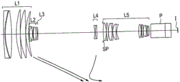
Fig. 1 is a lens cross-sectional view of a zoom lens according to numerical embodiment 1, which is focused on infinity at a wide-angle end.
Fig. 2A is an aberration diagram of a zoom lens according to numerical embodiment 1 focused on infinity at the wide-angle end.
Fig. 2B is an aberration diagram of a zoom lens according to numerical embodiment 1 focused at infinity at f-145.5 mm.
Fig. 2C is an aberration diagram of a zoom lens according to numerical embodiment 1 focused at infinity at f-304.3 mm.
Fig. 2D is an aberration diagram of a zoom lens according to numerical embodiment 1 focused at infinity at a telephoto end.
Fig. 3 is a lens cross-sectional view of a zoom lens according to numerical embodiment 2, which is focused on infinity at a wide-angle end.
Fig. 4A is an aberration diagram of a zoom lens according to numerical embodiment 2 focused on infinity at the wide-angle end.
Fig. 4B is an aberration diagram of a zoom lens according to numerical embodiment 2 focused at infinity at f-145.5 mm.
Fig. 4C is an aberration diagram of a zoom lens according to numerical embodiment 2 focused at infinity at f-304.3 mm.
Fig. 4D is an aberration diagram of a zoom lens according to numerical embodiment 2 focused at infinity at a telephoto end.
Fig. 5 is a lens cross-sectional view of a zoom lens according to numerical embodiment 3, which is focused on infinity at a wide-angle end.
Fig. 6A is an aberration diagram of a zoom lens according to numerical embodiment 3 focused on infinity at the wide-angle end.
Fig. 6B is an aberration diagram of a zoom lens according to numerical embodiment 3 focused at infinity at f-145.5 mm.
Fig. 6C is an aberration diagram of a zoom lens according to numerical embodiment 3 focused at infinity at f-304.3 mm.
Fig. 6D is an aberration diagram of a zoom lens according to numerical embodiment 3 focused at infinity at a telephoto end.
Fig. 7 is a lens cross-sectional view of a zoom lens according to numerical embodiment 4, which is focused on infinity at a wide-angle end.
Fig. 8A is an aberration diagram of a zoom lens according to numerical embodiment 4 focused on infinity at the wide-angle end.
Fig. 8B is an aberration diagram of a zoom lens according to numerical embodiment 4 focused at infinity at f-145.5 mm.
Fig. 8C is an aberration diagram of a zoom lens according to numerical embodiment 4 focused at infinity at f-200.5 mm.
Fig. 8D is an aberration diagram of a zoom lens according to numerical embodiment 4 focused at infinity at f-304.3 mm.
Fig. 8E is an aberration diagram of a zoom lens according to numerical embodiment 4 focused at infinity at a telephoto end.
Fig. 9 is a lens cross-sectional view of a zoom lens according to numerical embodiment 5, which is focused on infinity at the wide-angle end.
Fig. 10A is an aberration diagram of a zoom lens according to numerical embodiment 5 focused on infinity at the wide-angle end.
Fig. 10B is an aberration diagram of a zoom lens according to numerical embodiment 5 focused at infinity at f-58.1 mm.
Fig. 10C is an aberration diagram of a zoom lens according to numerical embodiment 5 focused at infinity at f 102.4 mm.
Fig. 10D is an aberration diagram of a zoom lens according to numerical embodiment 5 focused at infinity at a telephoto end.
Fig. 11 is a lens cross-sectional view of a zoom lens according to numerical embodiment 6, which is focused on infinity at the wide-angle end.
Fig. 12A is an aberration diagram of a zoom lens according to numerical embodiment 6 focused on infinity at the wide-angle end.
Fig. 12B is an aberration diagram of a zoom lens according to numerical embodiment 6 focused at infinity at f-233.6 mm.
Fig. 12C is an aberration diagram of a zoom lens according to numerical embodiment 6 focused at infinity at f-586.8 mm.
Fig. 12D is an aberration diagram of a zoom lens according to numerical embodiment 6 focused at infinity at a telephoto end.
Fig. 13A is a diagram illustrating an optical path at the wide-angle end in a zoom lens of numerical embodiment 1.
Fig. 13B is a diagram showing an optical path at f ═ 145.5mm in the zoom lens of numerical embodiment 1.
Fig. 13C is a diagram showing an optical path of the zoom lens of numerical embodiment 1 at the telephoto end.
Fig. 14 is a schematic diagram showing a main part of an image pickup apparatus of the present invention.
Detailed Description
Preferred embodiments of the present invention will now be described in detail based on the accompanying drawings.
First, the characteristics of the zoom lens of the present invention are described based on conditional expressions. The movement loci of the second lens unit and the third lens unit of the zoom lens of the present invention are defined such that the zoom lens can achieve a wide angle of view, a high zoom ratio, a reduction in size and weight, and high optical performance over the entire zoom range.
The zoom lens and the image pickup apparatus having the zoom lens of the present invention include, in order from an object side to an image side, a first lens unit having a positive refractive power, a second lens unit having a negative refractive power, a third lens unit having a negative refractive power, an intermediate lens group including at least one lens unit, and a rear lens group including at least one lens unit. The aperture stop is placed either on the object side of the rear lens group or inside the rear lens group. The first lens unit is configured not to move for zooming, the second lens unit is configured to move for zooming, the third lens unit is configured to move for zooming, and the intermediate lens group is configured to move for zooming. The lens unit closest to the object side in the rear lens group is configured not to move for zooming. This means that if the rear lens group includes only one lens unit, the rear lens group is configured not to move for zooming, and if the rear lens group includes more than one lens unit, the lens unit closest to the object in the rear lens group is configured not to move for zooming. In addition, the zoom lens is configured such that a distance between adjacent lens units changes for zooming.
The zoom lens satisfies the following expression:
1.3< L2max/L2w <3.0, and (1)
0.8<L2max/L2t<4.0,···(2)
Where L2w is a distance between the second lens unit and the third lens unit at the wide-angle end, L2t is a distance between the second lens unit and the third lens unit at the telephoto end, and L2max is a maximum distance between the second lens unit and the third lens unit in a zoom range between a focal length ftm1 and a focal length ftm2, ftm1 and ftm2 being defined as follows, respectively:
ftm1=fw×Z0.7and (a) and
ftm2=fw×Z0.9,···(b)
where fw is a focal length of the zoom lens at the wide-angle end, and Z is a zoom ratio.
Fig. 13A, 13B, and 13C are diagrams illustrating zoom lenses of numerical embodiment 1 of the present invention at the wide-angle end, 145.5mm (fw × Z) at f, respectively (fw × Z)0.7) And a view of the optical path at the telephoto end. "L1" to "L5" respectively represent the first to the thirdFive lens units. In the present invention, the moving loci of the second lens and the third lens are set so that the distance between the second lens unit and the third lens unit can be from the wide-angle end to the zooming intermediate range (fw × Z)0.7To fwxZ0.9) Is widened and becomes a predetermined distance for zooming from the zoom intermediate range to the telephoto end. Such an optical effect is described.
In the positive-lead type zoom lens, the beam height of the principal ray among the off-axis rays passing through the first lens unit is particularly in the zoom intermediate range (fwxZ)0.7To fwxZ0.9) Starts to fall off, and thus field curvature tends to occur in the direction of overcorrection (toward the image side). As can be seen in fig. 13A, 13B, and 13C, by moving the third lens unit away from the second lens unit toward the image side, the beam height of the off-axis rays passing through the third lens unit is reduced, which reduces curvature of field in the overcorrection direction occurring in the third lens unit. Therefore, it is possible to favorably correct the curvature of field in the overcorrected direction that tends to occur in the zoom intermediate range.
Expressions (1) and (2) are defined in the zoom intermediate range (fw × Z)0.7To fwxZ0.9) Is between the second lens unit and the third lens unit. By satisfying expression (1), the zoom lens can favorably correct curvature of field in the zoom intermediate range, thereby achieving high optical performance over the entire zoom range. When the zoom lens does not satisfy the upper limit of expression (1), the distance between the second lens unit and the third lens unit becomes so long that it becomes difficult to correct axial chromatic aberration in the zoom intermediate range. When the zoom lens does not satisfy the lower limit of expression (1), the distance between the second lens unit and the third lens unit is not sufficiently long with respect to the distance at the wide-angle end, and the above-described effect of curvature of field correction becomes so small that it becomes difficult to achieve high optical performance over the entire zoom range.
In addition, by satisfying expression (2), the zoom lens realizes both size reduction and high optical performance. When the zoom lens does not satisfy the upper limit of expression (2), the distance between the second lens unit and the third lens unit becomes so long that it becomes difficult to correct axial chromatic aberration in the zoom intermediate range. When the zoom lens does not satisfy the lower limit of expression (2), the distance between the second lens unit and the third lens unit at the telephoto end becomes too long with respect to the distance in the zoom intermediate range. Therefore, the combined focal length of the second lens unit and the third lens unit becomes short, and the zooming action assigned to the second lens unit and the third lens unit becomes small. As a result, the zoom ratio is reduced, making it difficult to reduce the size of the zoom lens. It is preferable when the values in expressions (1) and (2) are set as follows:
1.32< L2max/L2w <2.20, and (1a)
0.9<L2max/L2t<3.0。···(2a)
As an additional mode of the zoom lens of the present invention, the rear lens group has at least two convex lenses and at least one concave lens, and is configured not to move for zooming.
As an additional mode of the zoom lens of the present invention, the rear lens group has at least two convex lenses and at least one concave lens. The lens unit LRR, which is one lens unit in the rear lens group, is configured to move for zooming. The zoom lens satisfies the following expression:
|mrr/drr|<0.1···(3)
where mrr is a maximum movement amount of the lens unit LRR in the entire zoom range, and drr is a distance between a surface of the lens unit LRR closest to the object side and a surface of the lens unit LRR closest to the image side. The lens unit LRR may be moved for zooming in a range satisfying expression (3) to correct off-axis aberration. In addition, by moving the lens unit LRR in conjunction with the zoom operation, defocus caused by zooming can be corrected.
As an additional mode of the zoom lens of the present invention, the zoom lens satisfies the following expression:
-10.0<f1×(f2+f3)/(f2×f3)<-2.0···(4)
where f1, f2, and f3 are the focal length of the first lens unit, the focal length of the second lens unit, and the focal length of the third lens unit, respectively. The numerical value of (f2 xf 3)/(f2+ f3) corresponds to the combined focal length of the second lens unit and the third lens unit. By satisfying expression (4), the zoom lens realizes both size reduction and high optical performance. When the zoom lens does not satisfy the upper limit of expression (4), the first lens unit has too strong refractive power with respect to the second lens unit, which makes it difficult to correct distortion at the wide-angle end or axial chromatic aberration at the telephoto end. When the zoom lens does not satisfy the lower limit of expression (4), the first lens unit has too weak refractive power with respect to the second lens unit, which particularly increases the size of the first lens unit, making size reduction difficult. It is preferable when the values in expression (4) are set as follows:
-8.5<f1×(f2+f3)/(f2×f3)<-3.5。···(4a)
as an additional mode of the zoom lens of the present invention, the zoom lens satisfies the following expression:
0.1<f2/f3<10.0···(5)
where f2 and f3 are the focal length of the second lens unit and the focal length of the third lens unit, respectively. When the zoom lens does not satisfy the upper limit of expression (5), the third lens unit has too strong refractive power with respect to the second lens unit, and the third lens unit becomes more sensitive to manufacturing errors at the telephoto end. In particular, curvature of field and coma occur more, thereby deteriorating manufacturability. When the zoom lens does not satisfy the lower limit of expression (5), the second lens unit has too strong refractive power with respect to the third lens unit, which increases aberrations occurring in the second lens unit, making it difficult to achieve high optical performance over the entire zoom range. It is preferable when the values in expression (5) are set as follows:
0.15<f2/f3<6.00.···(5a)
as an additional mode of the zoom lens of the present invention, the second lens unit and the third lens unit collectively include at least one convex lens and at least two concave lenses. This lens configuration enables the lenses constituting the second lens unit and the third lens unit to have appropriate refractive powers so that aberrations in the zoom intermediate range and axial chromatic aberration at the telephoto end can be favorably corrected.
As an additional mode of the zoom lens of the present invention, the second lens unit or the third lens unit has at least one aspherical surface. This enables effective correction of curvature of field and spherical aberration in the intermediate range of zooming.
As an additional mode of the zoom lens of the present invention, the zoom lens satisfies the following expression:
-2<(R2+R3)/(R2-R3)<30···(6)
where R2 is a radius of curvature of a surface of the second lens unit closest to the image side, and R3 is a radius of curvature of a surface of the third lens unit closest to the object side. When the zoom lens does not satisfy the upper limit of expression (6), the difference between the radius of curvature of the surface of the second lens unit closest to the image side and the radius of curvature of the surface of the third lens unit closest to the object side becomes small, making it difficult to favorably correct aberrations in the zoom intermediate range and the telephoto end. When the zoom lens does not satisfy the lower limit of expression (6), the difference between the radius of curvature of the surface of the second lens unit closest to the image side and the radius of curvature of the surface of the third lens unit closest to the object side becomes large, which makes the distance between the second lens unit and the third lens unit sensitive to manufacturing errors. It is preferable when the values in expression (6) are set as follows:
-1<(R2+R3)/(R2-R3)<20.···(6a)
in addition, the image pickup apparatus of the present invention is characterized by including the zoom lens of any of the embodiments and a solid-state image pickup element having a predetermined effective image pickup range for receiving an optical image formed by the zoom lens.
A specific configuration of a zoom lens of the present invention is described based on the features of the lens configurations of numerical embodiments 1 to 6 corresponding to embodiments 1 to 6.
[ example 1]
Fig. 1 is a lens cross-sectional view of a zoom lens of embodiment 1 (numerical embodiment 1) of the present invention focusing on infinity at the wide-angle end. FIGS. 2A, 2B, 2C and 2D are, at the wide angle end, a focal length of 145.5mm (fw × Z), respectively, of the zoom lens of numerical embodiment 10.7) Focal length 304.3mm (fw × Z)0.9) And longitudinal aberration diagrams of the telephoto end. In all longitudinal aberration diagrams, the zoom lens is focused at infinity. The value of the focal length is a value in a numerical example given later expressed in millimeters. This also applies to the rest of the numerical embodiments. The focal length of 145.5mm is from fw × Z0.7To fwxZ0.9In a zoom position in which the distance between the second lens unit and the third lens unit is maximum.
The zoom lens in fig. 1 includes, in order from the object side, a first lens unit L1 for focusing having a positive refractive power, a second lens unit L2 for zooming and a third lens unit L3 having a negative refractive power and moving to the image side for zooming from the wide-angle end to the telephoto end, a fourth lens unit L4 having a negative refractive power and nonlinearly moving on the optical axis in conjunction with the movement of the second lens unit L2 and the third lens unit L3 to correct an image plane displacement caused by zooming, and a fifth lens unit L5 configured not to move for zooming and to perform an imaging action. In the present embodiment, the fourth lens unit L4 forms an intermediate lens group.
In the present embodiment, the second lens unit L2, the third lens unit L3, and the fourth lens unit L4 constitute a zoom system. "SP" denotes an aperture stop and is placed between the fourth lens unit L4 and the fifth lens unit L5. The aperture stop does not move in the optical axis direction for zooming. "P" denotes a glass block corresponding to an optical filter or a color separation optical system disposed inside an image pickup apparatus to which the zoom lens of the present invention is connected. "I" is the image plane. When the zoom lens is used as an image pickup optical system for a broadcast television camera, a video camera, or a digital still camera, the image plane I is, for example, an image pickup surface of a solid-state image pickup element (photoelectric conversion element) that receives an optical image formed by the zoom lens and photoelectrically converts it. When the zoom lens is used as an image pickup optical system of a film camera, the image plane I is a film plane sensitive to an optical image formed by the zoom lens.
In the longitudinal aberration diagram, a solid line and a two-dot chain line in a portion showing spherical aberration indicate an e line and a g line, respectively. In the portion showing astigmatism, broken lines and solid lines denote a meridional image plane and a sagittal image plane, respectively. In the portion showing the lateral chromatic aberration, the two-dot chain line indicates a g-line. Further, "ω" represents a half view angle, and "Fno" represents an f-number. In the longitudinal aberration diagram, spherical aberration is expressed on a scale in the range of-0.4 mm to 0.4mm, astigmatism is expressed on a scale in the range of-0.4 mm to 0.4mm, distortion is expressed on a scale in the range of-10% to 10%, and lateral chromatic aberration is expressed on a scale in the range of-0.05 mm to 0.05 mm. In the following embodiments, the wide-angle end and the telephoto end refer to zoom positions of available ends of a zoom range in which the second lens unit L2 for zooming can mechanically move on the optical axis.
Next, a description is given of a lens configuration of the lens unit of the present embodiment. The first lens unit L1 corresponds to the 1 st to 10 th surfaces, the second lens unit L2 corresponds to the 11 th to 16 th surfaces, the third lens unit L3 corresponds to the 17 th to 18 th surfaces, the fourth lens unit L4 corresponds to the 19 th to 21 th surfaces, and the fifth lens unit L5 corresponds to the 23 rd to 42 th surfaces. The second lens unit L2 includes a total of three lenses (including a convex lens and a concave lens), and the third lens unit L3 includes one concave lens.
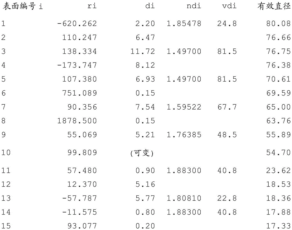
A description is given of numerical example 1 corresponding to example 1. In not only numerical embodiment 1, but also all numerical embodiments, "i" denotes the number of surfaces (optical surfaces) from the object side, "ri" denotes a radius of curvature of the i-th surface from the object side, and "di" denotes a distance (on the optical axis) between the i-th surface and the (i +1) -th surface from the object side. In addition, "ndi" and "vdi" denote a refractive index and an abbe number of the medium (optical member) between the i-th surface and the (i +1) -th surface, respectively, and "BF" denotes a back focus in air. Note that abbe number ν is expressed as follows:
ν=(Nd-1)/(NF-NC)
wherein NF, Nd and NC are the refractive indices of F-line (486.1nm), d-line (587.6nm) and C-line (656.3nm), respectively, of Fraunhofer (Fraunhofer). When the X axis is the optical axis direction, the H axis is perpendicular to the optical axis, and the traveling direction of light is positive, the aspherical shape is expressed as:

where R is the paraxial radius of curvature, k is the conic constant, and a4, a6, A8, a10, a12, a14, and a16 are each aspheric coefficients. Further, "e-Z" indicates "X10-Z”。
Table 1 shows numerical values in the conditional expressions used in the present embodiment. The present embodiment satisfies expressions (1), (2), (4) to (6). Since the movement loci of the second lens unit and the third lens unit are appropriately set, the zoom lens of the present embodiment favorably corrects aberrations over the entire zoom range, thereby achieving both high optical performance and reductions in size and weight. The zoom lens of the present invention must satisfy expressions (1) and (2), but does not necessarily satisfy expressions (3) to (6). Nevertheless, when at least one of expressions (3) to (6) is satisfied, a better effect is produced. The same is true for the remaining embodiments.
Fig. 14 is a schematic diagram of an image pickup apparatus (television camera system) using the zoom lens of any of the embodiments as its image pickup optical system. In fig. 14, reference numeral "101" denotes the zoom lens of any one of embodiments 1 to 6, and "124" denotes a camera. The zoom lens 101 may be attached to the camera 124 and detached from the camera 124. Reference numeral "125" denotes an image pickup apparatus formed by attaching the zoom lens 101 to the camera 124. The zoom lens 101 has a first lens unit F, a zoom part LZ, and a rear lens group R for forming an image. The first lens unit F includes a lens unit for focusing. The zoom part LZ includes a second lens unit and a third lens unit that move on the optical axis for zooming, and a fourth lens unit that moves on the optical axis for correcting an image plane displacement caused by zooming. "SP" denotes an aperture stop. Reference numerals "114" and "115" denote driving mechanisms (such as a screw or a cam) that drive the first lens unit F and the zoom part LZ in the optical axis direction, respectively. Reference numerals "116" to "118" are motors (driving means) that electrically drive the driving mechanism 114, the driving mechanism 115, and the aperture stop SP, respectively. Reference numerals "119" to "121" are detectors (such as encoders, potentiometers, or photosensors) that detect the position of the first lens unit F on the optical axis, the position of the zoom part LZ on the optical axis, and the aperture of the aperture stop SP, respectively. In the camera 124, "109" denotes a glass block corresponding to an optical filter or a color separation optical system in the camera 124, and "110" denotes a solid-state image pickup element (photoelectric conversion element) such as a CCD or CMOS sensor that receives an optical image of an object formed by the zoom lens 101. Further, "111" and "122" are CPUs that control driving of the camera 124 and the zoom lens 101, respectively.
When the zoom lens of the present invention is thus applied to an image pickup apparatus, or applied in the example of the television camera described above, the image pickup apparatus can achieve high optical performance.
[ example 2]
Fig. 3 is a lens cross-sectional view of a zoom lens of embodiment 2 (numerical embodiment 2) of the present invention focusing on infinity at the wide-angle end. FIGS. 4A, 4B, 4C and 4D are numerical values of a zoom lens of example 2 at a wide angle end and a focal length of 145.5mm (fw × Z), respectively0.7) Focal length 304.3mm (fw × Z)0.9) And a longitudinal aberration map of the telephoto end. In all longitudinal aberration diagrams, the zoom lens is focused at infinity. The focal length of 304.3mm is from fw × Z0.7To fwxZ0.9In a zoom position in which the distance between the second lens unit and the third lens unit is maximum.
The zoom lens in fig. 3 includes, in order from the object side, a first lens unit L1 for focusing having a positive refractive power, a second lens unit L2 for zooming and a third lens unit L3 having a negative refractive power and moving to the image side for zooming from the wide-angle end to the telephoto end, a fourth lens unit L4 having a negative refractive power and nonlinearly moving on the optical axis in conjunction with the movement of the second lens unit L2 and the third lens unit L3 to correct an image plane displacement caused by zooming, and a fifth lens unit L5 configured not to move for zooming and to perform an imaging action. In the present embodiment, the fourth lens unit L4 forms an intermediate lens group. The lens configuration of the lens unit is the same as that in numerical embodiment 1.
Table 1 shows numerical values in the conditional expressions used in the present embodiment. The present embodiment satisfies expressions (1), (2), (4) to (6). Since the movement loci of the second lens unit and the third lens unit are appropriately set, the zoom lens of the present embodiment favorably corrects aberrations over the entire zoom range, thereby achieving both high optical performance and reductions in size and weight.
[ example 3]
Fig. 5 is a lens cross-sectional view of a zoom lens of embodiment 3 (numerical embodiment 3) of the present invention focusing on infinity at the wide-angle end. Fig. 6A, 6B, 6C, and 6D are numerical examples 3 of a zoom lens at a wide angle end and a focal length of 145.5mm (fwxz), respectively (fw × Z)0.7) Focal length 304.3mm (fw × Z)0.9) And a longitudinal aberration map of the telephoto end. In all longitudinal aberration diagrams, the zoom lens is focused at infinity. The focal length of 145.5mm is from fw × Z0.7To fwxZ0.9In a zoom position in which the distance between the second lens unit and the third lens unit is maximum.
The zoom lens in fig. 5 includes, in order from the object side, a first lens unit L1 for focusing having a positive refractive power, a second lens unit L2 for zooming and a third lens unit L3 having a negative refractive power and moving to the image side for zooming from the wide-angle end to the telephoto end, a fourth lens unit L4 and a fifth lens unit L5 having a negative refractive power and a positive refractive power, respectively, and moving nonlinearly on the optical axis in conjunction with the movement of the second lens unit L2 and the third lens unit L3, and a sixth lens unit L6 configured not to move for zooming and to perform an imaging action. In the present embodiment, the fourth lens unit L4 and the fifth lens unit L5 form an intermediate lens group.
Next, a description is given of a lens configuration of the lens unit of the present embodiment. The first lens unit L1 corresponds to the 1 st to 10 th surfaces, the second lens unit L2 corresponds to the 11 th to 16 th surfaces, the third lens unit L3 corresponds to the 17 th to 18 th surfaces, the fourth lens unit L4 corresponds to the 19 th to 21 th surfaces, the fifth lens unit L5 corresponds to the 22 th to 25 th surfaces, and the sixth lens unit L6 corresponds to the 27 th to 42 th surfaces. The second lens unit L2 includes a total of three lenses of a convex lens and a concave lens, and the third lens unit L3 includes one concave lens.
Table 1 shows numerical values in the conditional expressions used in the present embodiment. The present embodiment satisfies expressions (1), (2), (4) to (6). Since the movement loci of the second lens unit and the third lens unit are appropriately set, the zoom lens of the present embodiment favorably corrects aberrations over the entire zoom range, thereby achieving both high optical performance and reductions in size and weight.
[ example 4]
Fig. 7 is a lens cross-sectional view of a zoom lens of embodiment 4 (numerical embodiment 4) of the present invention focusing on infinity at the wide-angle end. Fig. 8A, 8B, 8C, 8D, and 8E are numerical examples 4 of a zoom lens at a wide angle end and a focal length of 145.5mm (fwxz), respectively (fw × Z)0.7) Focal length 200.5mm (at from fw × Z)0.7To fwxZ0.9A zoom position where the distance between the second lens unit and the third lens unit is maximum), a focal length of 304.3mm (fwxz)0.9) And a longitudinal aberration map of the telephoto end. In all longitudinal aberration diagrams, the zoom lens is focused at infinity. The focal length of 200.5mm is from fw × Z0.7To fwxZ0.9In a zoom position in which the distance between the second lens unit and the third lens unit is maximum.
The zoom lens in fig. 7 includes, in order from the object side, a first lens unit L1 for focusing having a positive refractive power, a second lens unit L2 for zooming, and a third lens unit L3 having a negative refractive power and moving to the image side for zooming from the wide-angle end to the telephoto end, a fourth lens unit L4 and a fifth lens unit L5 having a negative refractive power and a positive refractive power, respectively, and moving nonlinearly on the optical axis in conjunction with the movement of the second lens unit L2 and the third lens unit L3, a sixth lens unit L6 configured not to move for zooming, and a seventh lens unit L7 configured to move for zooming. In the present embodiment, the fourth lens unit L4 and the fifth lens unit L5 form an intermediate lens group, and the sixth lens unit L6 and the seventh lens unit L7 form a rear lens group. In addition, the seventh lens unit L7 corresponds to a lens unit LRR that is a part of the rear lens group.
Next, a description is given of a lens configuration of the lens unit of the present embodiment. The first lens unit L1 corresponds to the 1 st to 10 th surfaces, the second lens unit L2 corresponds to the 11 th to 12 th surfaces, the third lens unit L3 corresponds to the 13 th to 18 th surfaces, the fourth lens unit L4 corresponds to the 19 th to 21 th surfaces, the fifth lens unit L5 corresponds to the 22 th to 25 th surfaces, the sixth lens unit L6 corresponds to the 27 th to 32 th surfaces, and the seventh lens unit L7 corresponds to the 33 th to 42 th surfaces. The second lens unit L2 includes one concave lens, and the third lens unit L3 includes a total of three lenses of a convex lens and a concave lens.
Table 1 shows numerical values in the conditional expressions used in the present embodiment. The present embodiment satisfies expressions (1) to (6). Since the movement loci of the second lens unit and the third lens unit are appropriately set, the zoom lens of the present embodiment favorably corrects aberrations over the entire zoom range, thereby achieving both high optical performance and reductions in size and weight.
[ example 5]
Fig. 9 is a lens cross-sectional view of a zoom lens of embodiment 5 (numerical embodiment 5) of the present invention focusing on infinity at the wide-angle end. Fig. 10A, 10B, 10C, and 10D are numerical examples 5 of a zoom lens at a wide-angle end and a focal length of 58.1mm (fw × Z), respectively0.7) Focal length 102.44mm (fw × Z)0.9) And a longitudinal aberration map of the telephoto end. In all longitudinal aberration diagrams, the zoom lens is focused at infinity. The focal length of 102.44mm is from fw × Z0.7To fwxZ0.9In a zoom position in which the distance between the second lens unit and the third lens unit is maximum.
The zoom lens in fig. 9 includes, in order from the object side, a first lens unit L1 for focusing having a positive refractive power, a second lens unit L2 for zooming and a third lens unit L3 having a negative refractive power and moving to the image side for zooming from the wide-angle end to the telephoto end, a fourth lens unit L4 and a fifth lens unit L5 having a negative refractive power and a positive refractive power, respectively, and moving nonlinearly on the optical axis in conjunction with the movement of the second lens unit L2 and the third lens unit L3, and a sixth lens unit L6 configured not to move for zooming and to perform an imaging action. In the present embodiment, the fourth lens unit L4 and the fifth lens unit L5 form an intermediate lens group.
Next, a description is given of a lens configuration of the lens unit of the present embodiment. The first lens unit L1 corresponds to the 1 st to 10 th surfaces, the second lens unit L2 corresponds to the 11 th to 17 th surfaces, the third lens unit L3 corresponds to the 18 th to 19 th surfaces, the fourth lens unit L4 corresponds to the 20 th to 22 th surfaces, the fifth lens unit L5 corresponds to the 23 th to 26 th surfaces, and the sixth lens unit L6 corresponds to the 28 th to 40 th surfaces. The second lens unit L2 includes a total of four lenses of a convex lens and a concave lens, and the third lens unit L3 includes one concave lens.
Table 1 shows numerical values in the conditional expressions used in the present embodiment. The present embodiment satisfies expressions (1), (2), (4) to (6). Since the movement loci of the second lens unit and the third lens unit are appropriately set, the zoom lens of the present embodiment favorably corrects aberrations over the entire zoom range, thereby achieving both high optical performance and reductions in size and weight.
[ example 6]
Fig. 11 is a lens cross-sectional view of a zoom lens of embodiment 6 (numerical embodiment 6) of the present invention focusing on infinity at the wide-angle end. Fig. 12A, 12B, 12C, and 12D are numerical examples 6 of a zoom lens at the wide angle end, a focal length 233.61mm (fw × Z), respectively0.7) Focal length 586.8mm (fw × Z)0.9) And a longitudinal aberration map of the telephoto end. In all longitudinal aberration diagrams, the zoom lens is focused at infinity. The focal length of 233.61mm is from fw × Z0.7To fwxZ0.9In a zoom position in which the distance between the second lens unit and the third lens unit is maximum.
The zoom lens in fig. 11 includes, in order from the object side, a first lens unit L1 for focusing having a positive refractive power, a second lens unit L2 for zooming and a third lens unit L3 having a negative refractive power and moving to the image side for zooming from the wide-angle end to the telephoto end, a fourth lens unit L4 and a fifth lens unit L5 having a positive refractive power and moving nonlinearly on the optical axis in conjunction with the movement of the second lens unit L2 and the third lens unit L3, and a sixth lens unit L6 configured not to move for zooming and to perform an imaging action. In the present embodiment, the fourth lens unit L4 and the fifth lens unit L5 form an intermediate lens group.
Next, a description is given of a lens configuration of the lens unit of the present embodiment. The first lens unit L1 corresponds to the 1 st to 10 th surfaces, the second lens unit L2 corresponds to the 11 th to 15 th surfaces, the third lens unit L3 corresponds to the 16 th to 18 th surfaces, the fourth lens unit L4 corresponds to the 19 th to 25 th surfaces, the fifth lens unit L5 corresponds to the 26 th to 27 th surfaces, and the sixth lens unit L6 corresponds to the 29 th to 49 th surfaces. The second lens unit L2 includes a total of three lenses of a convex lens and a concave lens, and the third lens unit L3 includes a total of two lenses of a convex lens and a concave lens.
Table 1 shows numerical values in the conditional expressions used in the present embodiment. The present embodiment satisfies expressions (1), (2), (4) to (6). Since the movement loci of the second lens unit and the third lens unit are appropriately set, the zoom lens of the present embodiment favorably corrects aberrations over the entire zoom range, thereby achieving both high optical performance and reductions in size and weight.
Numerical example 1
[ unit: mm ]
Surface data


Aspheric data
18 th surface
K=6.06641e+001
A4=1.21406e-006
A6=1.81961e-009
A8=1.60180e-012
Various data

Zoom lens unit data

[ numerical example 2]
[ unit: mm ]
Surface data


Aspheric data
18 th surface
K=3.88016e+001
A4=-4.96524e-006
A6=-5.02500e-009
A8=2.51247e-013
Various data


Zoom lens unit data

[ numerical example 3]
[ unit: mm ]
Surface data


Aspheric data
18 th surface
K=1.10614e+001
A4=-1.04495e-007
A6=1.49273e-009
A8=-2.78561e-012
Various data


Zoom lens unit data

[ numerical example 4]
[ unit: mm ]
Surface data


Aspheric data
Eleventh surface
K=2.34652e+001
A4=1.00780e-006
A6=-2.02900e-009
A8=8.13926e-012
Various data

Zoom lens unit data

[ numerical example 5]
[ unit: mm ]
Surface data

Aspheric data
Surface No. 26
K=-3.55603e+006
A4=4.90701e-007
A6=4.39091e-009
A8=-4.52046e-011
A10=2.10063e-013
A12=-3.56390e-016
Various data

Zoom lens unit data


Numerical example 6
[ unit: mm ]
Surface data


Aspheric data
18 th surface
K=-3.28820e+004
A4=2.40636e-008
A6=-2.71419e-010
A8=3.15903e-013
No. 20 surface
K=-2.02027e+013
A4=3.75968e-007
A6=1.77693e-011
A8=-2.46630e-015
Surface No. 26
K=1.07280e+002
A4=-3.52261e-007
A6=-4.00314e-012
A8=-3.41561e-015
Various data


Zoom lens unit data

TABLE 1


While the present invention has been described with reference to exemplary embodiments, it is to be understood that the invention is not limited to the disclosed exemplary embodiments. The scope of the following claims is to be accorded the broadest interpretation so as to encompass all such modifications and equivalent structures and functions.
Claims (8)
1. A zoom lens comprising, in order from an object side to an image side thereof:
a first lens unit having a positive refractive power and configured not to move for zooming;
a second lens unit having a negative refractive power and configured to move at the time of zooming;
a third lens unit having a negative refractive power and configured to move at the time of zooming;
an intermediate lens group including at least one lens unit and configured to move upon zooming; and
a rear lens group including at least one lens unit, a lens unit closest to the object side in the rear lens group being configured not to move for zooming,
wherein the zoom lens includes an aperture stop disposed on an object side with respect to the rear lens group or disposed in the rear lens group,
wherein a distance between each pair of adjacent lens units changes upon zooming, and
wherein the zoom lens satisfies a conditional expression
1.3<L2max/L2w<3.0,
0.8< L2max/L2t <4.0, and
0.1<f2/f3<6.0,
where L2w is a distance between the second lens unit and the third lens unit at the wide-angle end, L2t is a distance between the second lens unit and the third lens unit at the telephoto end, and L2max is a maximum distance between the second lens unit and the third lens unit in a zoom range from a focal length ftm1 to a focal length ftm2, f2 and f3 are a focal length of the second lens unit and a focal length of the third lens unit, respectively, and ftm1 and ftm2 are defined as ftm1 and ftm2, respectively
ftm1=fw×Z0.7And an
ftm2=fw×Z0.9,
Where fw is a focal length of the zoom lens at the wide-angle end, and Z is a zoom ratio of the zoom lens.
2. The variable focus lens of claim 1 wherein
The rear lens group includes two convex lenses and one concave lens, and is configured not to move for zooming.
3. The variable focus lens of claim 1 wherein
The rear lens group includes two convex lenses and a concave lens,
a lens unit LRR included in the rear lens group and arranged on the image side with respect to a lens unit closest to the object side included in the rear lens group is configured to move upon zooming, an
The zoom lens satisfies a conditional expression
|mrr/drr|<0.1,
Where mrr is a maximum movement amount of the lens unit LRR in the entire zoom range of the zoom lens, and drr is a distance on the optical axis between a surface of the lens unit LRR closest to the object side and a surface of the lens unit LRR closest to the image side.
4. The variable focus lens of claim 1 wherein
The zoom lens satisfies a conditional expression
-10.0<f1×(f2+f3)/(f2×f3)<-2.0,
Where f1, f2, and f3 are the focal length of the first lens unit, the focal length of the second lens unit, and the focal length of the third lens unit, respectively.
5. The variable focus lens of claim 1 wherein
The second lens unit and the third lens unit collectively include one convex lens and two concave lenses.
6. The variable focus lens of claim 1 wherein
The second lens unit and the third lens unit include aspherical surfaces.
7. The variable focus lens of claim 1 wherein
The zoom lens satisfies a conditional expression
-2<(R2+R3)/(R2-R3)<30,
Where R2 is a radius of curvature of a surface of the second lens unit closest to the image side, and R3 is a radius of curvature of a surface of the third lens unit closest to the object side.
8. An image pickup apparatus characterized by comprising:
a variable focus lens as claimed in any one of claims 1 to 7; and
an image pickup element configured to receive an image formed by the zoom lens.
Applications Claiming Priority (2)
| Application Number | Priority Date | Filing Date | Title |
|---|---|---|---|
| JP2017021499A JP6862203B2 (en) | 2017-02-08 | 2017-02-08 | Zoom lens and imaging device with it |
| JP2017-021499 | 2017-02-08 |
Publications (2)
| Publication Number | Publication Date |
|---|---|
| CN108398773A CN108398773A (en) | 2018-08-14 |
| CN108398773B true CN108398773B (en) | 2021-04-09 |
Family
ID=61131888
Family Applications (1)
| Application Number | Title | Priority Date | Filing Date |
|---|---|---|---|
| CN201810109508.3A Active CN108398773B (en) | 2017-02-08 | 2018-02-05 | Zoom lens and image pickup apparatus having the same |
Country Status (4)
| Country | Link |
|---|---|
| US (1) | US10670845B2 (en) |
| EP (1) | EP3361301B1 (en) |
| JP (1) | JP6862203B2 (en) |
| CN (1) | CN108398773B (en) |
Families Citing this family (10)
| Publication number | Priority date | Publication date | Assignee | Title |
|---|---|---|---|---|
| JP7039241B6 (en) * | 2017-10-12 | 2022-04-18 | キヤノン株式会社 | Zoom lens and image pickup device |
| JP7129178B2 (en) | 2018-02-28 | 2022-09-01 | キヤノン株式会社 | Zoom lens and imaging device |
| JP6772209B2 (en) | 2018-02-28 | 2020-10-21 | キヤノン株式会社 | Zoom lens and imaging device |
| JP7207854B2 (en) | 2018-02-28 | 2023-01-18 | キヤノン株式会社 | Zoom lens and imaging device |
| CN109164563B (en) * | 2018-09-17 | 2020-08-18 | 河北汉光重工有限责任公司 | Large-relative-aperture high-definition continuous zooming optical system with super-large image surface |
| JP2020085934A (en) * | 2018-11-15 | 2020-06-04 | キヤノン株式会社 | Zoom lens and imaging apparatus |
| JP7286341B2 (en) * | 2019-02-22 | 2023-06-05 | キヤノン株式会社 | Zoom lens and imaging device |
| JP7344714B2 (en) | 2019-08-16 | 2023-09-14 | キヤノン株式会社 | Zoom lenses and imaging devices |
| JP2022123453A (en) | 2021-02-12 | 2022-08-24 | キヤノン株式会社 | Zoom lens and imaging apparatus |
| JP2022123454A (en) | 2021-02-12 | 2022-08-24 | キヤノン株式会社 | Zoom lens and image capturing device |
Citations (2)
| Publication number | Priority date | Publication date | Assignee | Title |
|---|---|---|---|---|
| JP2016024341A (en) * | 2014-07-22 | 2016-02-08 | キヤノン株式会社 | Zoom lens and image capturing device having the same |
| JP2016173529A (en) * | 2015-03-18 | 2016-09-29 | キヤノン株式会社 | Zoom lens and imaging device mounted with the same |
Family Cites Families (20)
| Publication number | Priority date | Publication date | Assignee | Title |
|---|---|---|---|---|
| JPH03293613A (en) * | 1990-04-12 | 1991-12-25 | Konica Corp | Zoom lens |
| JP5009758B2 (en) * | 2007-11-26 | 2012-08-22 | 富士フイルム株式会社 | Projection zoom lens and projection display device |
| JP5675473B2 (en) * | 2011-04-15 | 2015-02-25 | キヤノン株式会社 | Zoom lens and imaging apparatus having the same |
| JP5721514B2 (en) * | 2011-04-15 | 2015-05-20 | キヤノン株式会社 | Zoom lens and imaging apparatus having the same |
| JP2013003384A (en) * | 2011-06-17 | 2013-01-07 | Konica Minolta Advanced Layers Inc | Large-diameter variable power optical system and image pickup apparatus |
| JP5809277B2 (en) * | 2011-08-30 | 2015-11-10 | 富士フイルム株式会社 | Magnification optical system and imaging device |
| JP6004829B2 (en) * | 2012-08-17 | 2016-10-12 | キヤノン株式会社 | Zoom lens and imaging apparatus having the same |
| CN104919355B (en) * | 2013-01-22 | 2017-05-03 | 富士胶片株式会社 | Zoom lens and image capturing device |
| JP6288916B2 (en) | 2013-01-23 | 2018-03-07 | キヤノン株式会社 | Zoom lens and imaging apparatus having the same |
| KR102001220B1 (en) * | 2013-03-12 | 2019-07-17 | 삼성전자주식회사 | Telephoto zoom lens system and photographing apparatus having the same |
| JP6418732B2 (en) | 2013-08-08 | 2018-11-07 | キヤノン株式会社 | Zoom lens and imaging apparatus having the same |
| JP2015094867A (en) | 2013-11-12 | 2015-05-18 | キヤノン株式会社 | Zoom lens and imaging apparatus including the same |
| JP6347590B2 (en) | 2013-11-12 | 2018-06-27 | キヤノン株式会社 | Zoom lens and imaging apparatus having the same |
| JP6529215B2 (en) | 2013-11-12 | 2019-06-12 | キヤノン株式会社 | Zoom lens and imaging device having the same |
| JP6251009B2 (en) | 2013-11-12 | 2017-12-20 | キヤノン株式会社 | Zoom lens and imaging apparatus having the same |
| JP6204852B2 (en) * | 2014-02-26 | 2017-09-27 | 富士フイルム株式会社 | Zoom lens and imaging device |
| JP2016109952A (en) | 2014-12-09 | 2016-06-20 | キヤノン株式会社 | Zoom lens and image capturing device having the same |
| JP6544957B2 (en) * | 2015-03-18 | 2019-07-17 | キヤノン株式会社 | Zoom lens and imaging device having the same |
| EP3159726A3 (en) | 2015-10-20 | 2017-07-05 | Canon Kabushiki Kaisha | Zoom lens and image pickup apparatus including the same |
| US9904043B2 (en) | 2015-10-20 | 2018-02-27 | Canon Kabushiki Kaisha | Zoom lens and image pickup apparatus including the same |
-
2017
- 2017-02-08 JP JP2017021499A patent/JP6862203B2/en active Active
-
2018
- 2018-01-31 EP EP18000080.4A patent/EP3361301B1/en active Active
- 2018-02-05 CN CN201810109508.3A patent/CN108398773B/en active Active
- 2018-02-06 US US15/889,520 patent/US10670845B2/en active Active
Patent Citations (2)
| Publication number | Priority date | Publication date | Assignee | Title |
|---|---|---|---|---|
| JP2016024341A (en) * | 2014-07-22 | 2016-02-08 | キヤノン株式会社 | Zoom lens and image capturing device having the same |
| JP2016173529A (en) * | 2015-03-18 | 2016-09-29 | キヤノン株式会社 | Zoom lens and imaging device mounted with the same |
Also Published As
| Publication number | Publication date |
|---|---|
| EP3361301A3 (en) | 2018-11-21 |
| JP2018128572A (en) | 2018-08-16 |
| US20180224640A1 (en) | 2018-08-09 |
| CN108398773A (en) | 2018-08-14 |
| EP3361301A1 (en) | 2018-08-15 |
| EP3361301B1 (en) | 2023-09-20 |
| US10670845B2 (en) | 2020-06-02 |
| JP6862203B2 (en) | 2021-04-21 |
Similar Documents
| Publication | Publication Date | Title |
|---|---|---|
| CN108398773B (en) | Zoom lens and image pickup apparatus having the same | |
| CN108535850B (en) | Zoom lens and image pickup apparatus including the same | |
| US11668899B2 (en) | Zoom lens, optical apparatus, and method for manufacturing zoom lens | |
| CN110244439B (en) | Zoom lens and image pickup apparatus | |
| CN108983404B (en) | Zoom lens and image pickup apparatus including the same | |
| US9726866B2 (en) | Zoom lens and image pickup device including the same | |
| US10670834B2 (en) | Zoom lens and image pickup apparatus | |
| CN109239896B (en) | Zoom lens and image pickup apparatus | |
| CN111796406B (en) | Zoom lens and imaging apparatus having the same | |
| CN113671674B (en) | Zoom lens and image pickup apparatus | |
| JP6545002B2 (en) | Zoom lens and imaging device having the same | |
| CN108700729B (en) | Zoom lens and imaging device | |
| JP2008225314A (en) | Zoom lens | |
| CN111751965B (en) | Zoom lens and imaging apparatus having the same | |
| WO2013031180A1 (en) | Zoom lens and imaging device | |
| US8964303B2 (en) | Zoom lens and image pickup apparatus having the same | |
| JP4833975B2 (en) | Zoom lens system and imaging optical apparatus having the same | |
| CN108279489B (en) | Zoom lens and image pickup apparatus | |
| US11703661B2 (en) | Optical system and optical apparatus | |
| CN112180575B (en) | Zoom lens and image pickup apparatus | |
| WO2013031181A1 (en) | Zoom lens and imaging device | |
| CN110850569A (en) | Zoom lens and imaging device | |
| JP6324000B2 (en) | Zoom lens and imaging apparatus having the same | |
| CN111983792B (en) | Zoom lens and imaging apparatus including the same | |
| CN111610619B (en) | Zoom lens and imaging device |
Legal Events
| Date | Code | Title | Description |
|---|---|---|---|
| PB01 | Publication | ||
| PB01 | Publication | ||
| SE01 | Entry into force of request for substantive examination | ||
| SE01 | Entry into force of request for substantive examination | ||
| GR01 | Patent grant | ||
| GR01 | Patent grant |