CN108377351B - Image processing apparatus and image processing method for laying out images on template - Google Patents
Image processing apparatus and image processing method for laying out images on template Download PDFInfo
- Publication number
- CN108377351B CN108377351B CN201810097547.6A CN201810097547A CN108377351B CN 108377351 B CN108377351 B CN 108377351B CN 201810097547 A CN201810097547 A CN 201810097547A CN 108377351 B CN108377351 B CN 108377351B
- Authority
- CN
- China
- Prior art keywords
- image
- images
- scene
- predetermined
- image groups
- Prior art date
- Legal status (The legal status is an assumption and is not a legal conclusion. Google has not performed a legal analysis and makes no representation as to the accuracy of the status listed.)
- Active
Links
Images


Classifications
-
- H—ELECTRICITY
- H04—ELECTRIC COMMUNICATION TECHNIQUE
- H04N—PICTORIAL COMMUNICATION, e.g. TELEVISION
- H04N5/00—Details of television systems
- H04N5/76—Television signal recording
- H04N5/91—Television signal processing therefor
-
- G—PHYSICS
- G06—COMPUTING; CALCULATING OR COUNTING
- G06F—ELECTRIC DIGITAL DATA PROCESSING
- G06F3/00—Input arrangements for transferring data to be processed into a form capable of being handled by the computer; Output arrangements for transferring data from processing unit to output unit, e.g. interface arrangements
- G06F3/12—Digital output to print unit, e.g. line printer, chain printer
- G06F3/1201—Dedicated interfaces to print systems
- G06F3/1223—Dedicated interfaces to print systems specifically adapted to use a particular technique
- G06F3/1237—Print job management
- G06F3/1242—Image or content composition onto a page
- G06F3/1243—Variable data printing, e.g. document forms, templates, labels, coupons, advertisements, logos, watermarks, transactional printing, fixed content versioning
-
- H—ELECTRICITY
- H04—ELECTRIC COMMUNICATION TECHNIQUE
- H04N—PICTORIAL COMMUNICATION, e.g. TELEVISION
- H04N1/00—Scanning, transmission or reproduction of documents or the like, e.g. facsimile transmission; Details thereof
- H04N1/00127—Connection or combination of a still picture apparatus with another apparatus, e.g. for storage, processing or transmission of still picture signals or of information associated with a still picture
- H04N1/00132—Connection or combination of a still picture apparatus with another apparatus, e.g. for storage, processing or transmission of still picture signals or of information associated with a still picture in a digital photofinishing system, i.e. a system where digital photographic images undergo typical photofinishing processing, e.g. printing ordering
- H04N1/00185—Image output
- H04N1/00196—Creation of a photo-montage, e.g. photoalbum
-
- G—PHYSICS
- G06—COMPUTING; CALCULATING OR COUNTING
- G06F—ELECTRIC DIGITAL DATA PROCESSING
- G06F18/00—Pattern recognition
- G06F18/20—Analysing
- G06F18/22—Matching criteria, e.g. proximity measures
-
- G—PHYSICS
- G06—COMPUTING; CALCULATING OR COUNTING
- G06F—ELECTRIC DIGITAL DATA PROCESSING
- G06F18/00—Pattern recognition
- G06F18/20—Analysing
- G06F18/24—Classification techniques
- G06F18/245—Classification techniques relating to the decision surface
-
- G—PHYSICS
- G06—COMPUTING; CALCULATING OR COUNTING
- G06F—ELECTRIC DIGITAL DATA PROCESSING
- G06F3/00—Input arrangements for transferring data to be processed into a form capable of being handled by the computer; Output arrangements for transferring data from processing unit to output unit, e.g. interface arrangements
- G06F3/12—Digital output to print unit, e.g. line printer, chain printer
- G06F3/1201—Dedicated interfaces to print systems
- G06F3/1223—Dedicated interfaces to print systems specifically adapted to use a particular technique
- G06F3/1237—Print job management
- G06F3/125—Page layout or assigning input pages onto output media, e.g. imposition
-
- G—PHYSICS
- G06—COMPUTING; CALCULATING OR COUNTING
- G06F—ELECTRIC DIGITAL DATA PROCESSING
- G06F3/00—Input arrangements for transferring data to be processed into a form capable of being handled by the computer; Output arrangements for transferring data from processing unit to output unit, e.g. interface arrangements
- G06F3/12—Digital output to print unit, e.g. line printer, chain printer
- G06F3/1201—Dedicated interfaces to print systems
- G06F3/1223—Dedicated interfaces to print systems specifically adapted to use a particular technique
- G06F3/1237—Print job management
- G06F3/126—Job scheduling, e.g. queuing, determine appropriate device
- G06F3/1263—Job scheduling, e.g. queuing, determine appropriate device based on job priority, e.g. re-arranging the order of jobs, e.g. the printing sequence
-
- G—PHYSICS
- G06—COMPUTING; CALCULATING OR COUNTING
- G06T—IMAGE DATA PROCESSING OR GENERATION, IN GENERAL
- G06T11/00—2D [Two Dimensional] image generation
- G06T11/60—Editing figures and text; Combining figures or text
-
- G—PHYSICS
- G06—COMPUTING; CALCULATING OR COUNTING
- G06V—IMAGE OR VIDEO RECOGNITION OR UNDERSTANDING
- G06V10/00—Arrangements for image or video recognition or understanding
- G06V10/70—Arrangements for image or video recognition or understanding using pattern recognition or machine learning
- G06V10/74—Image or video pattern matching; Proximity measures in feature spaces
- G06V10/75—Organisation of the matching processes, e.g. simultaneous or sequential comparisons of image or video features; Coarse-fine approaches, e.g. multi-scale approaches; using context analysis; Selection of dictionaries
-
- G—PHYSICS
- G06—COMPUTING; CALCULATING OR COUNTING
- G06V—IMAGE OR VIDEO RECOGNITION OR UNDERSTANDING
- G06V20/00—Scenes; Scene-specific elements
- G06V20/35—Categorising the entire scene, e.g. birthday party or wedding scene
-
- G—PHYSICS
- G06—COMPUTING; CALCULATING OR COUNTING
- G06V—IMAGE OR VIDEO RECOGNITION OR UNDERSTANDING
- G06V20/00—Scenes; Scene-specific elements
- G06V20/40—Scenes; Scene-specific elements in video content
- G06V20/41—Higher-level, semantic clustering, classification or understanding of video scenes, e.g. detection, labelling or Markovian modelling of sport events or news items
-
- G—PHYSICS
- G06—COMPUTING; CALCULATING OR COUNTING
- G06V—IMAGE OR VIDEO RECOGNITION OR UNDERSTANDING
- G06V40/00—Recognition of biometric, human-related or animal-related patterns in image or video data
- G06V40/10—Human or animal bodies, e.g. vehicle occupants or pedestrians; Body parts, e.g. hands
- G06V40/16—Human faces, e.g. facial parts, sketches or expressions
-
- H—ELECTRICITY
- H04—ELECTRIC COMMUNICATION TECHNIQUE
- H04N—PICTORIAL COMMUNICATION, e.g. TELEVISION
- H04N1/00—Scanning, transmission or reproduction of documents or the like, e.g. facsimile transmission; Details thereof
- H04N1/00127—Connection or combination of a still picture apparatus with another apparatus, e.g. for storage, processing or transmission of still picture signals or of information associated with a still picture
- H04N1/00132—Connection or combination of a still picture apparatus with another apparatus, e.g. for storage, processing or transmission of still picture signals or of information associated with a still picture in a digital photofinishing system, i.e. a system where digital photographic images undergo typical photofinishing processing, e.g. printing ordering
- H04N1/00185—Image output
-
- H—ELECTRICITY
- H04—ELECTRIC COMMUNICATION TECHNIQUE
- H04N—PICTORIAL COMMUNICATION, e.g. TELEVISION
- H04N1/00—Scanning, transmission or reproduction of documents or the like, e.g. facsimile transmission; Details thereof
- H04N1/32—Circuits or arrangements for control or supervision between transmitter and receiver or between image input and image output device, e.g. between a still-image camera and its memory or between a still-image camera and a printer device
- H04N1/32101—Display, printing, storage or transmission of additional information, e.g. ID code, date and time or title
- H04N1/32128—Display, printing, storage or transmission of additional information, e.g. ID code, date and time or title attached to the image data, e.g. file header, transmitted message header, information on the same page or in the same computer file as the image
-
- H—ELECTRICITY
- H04—ELECTRIC COMMUNICATION TECHNIQUE
- H04N—PICTORIAL COMMUNICATION, e.g. TELEVISION
- H04N21/00—Selective content distribution, e.g. interactive television or video on demand [VOD]
- H04N21/40—Client devices specifically adapted for the reception of or interaction with content, e.g. set-top-box [STB]; Operations thereof
- H04N21/43—Processing of content or additional data, e.g. demultiplexing additional data from a digital video stream; Elementary client operations, e.g. monitoring of home network or synchronising decoder's clock; Client middleware
- H04N21/431—Generation of visual interfaces for content selection or interaction; Content or additional data rendering
- H04N21/4312—Generation of visual interfaces for content selection or interaction; Content or additional data rendering involving specific graphical features, e.g. screen layout, special fonts or colors, blinking icons, highlights or animations
- H04N21/4316—Generation of visual interfaces for content selection or interaction; Content or additional data rendering involving specific graphical features, e.g. screen layout, special fonts or colors, blinking icons, highlights or animations for displaying supplemental content in a region of the screen, e.g. an advertisement in a separate window
-
- H—ELECTRICITY
- H04—ELECTRIC COMMUNICATION TECHNIQUE
- H04N—PICTORIAL COMMUNICATION, e.g. TELEVISION
- H04N23/00—Cameras or camera modules comprising electronic image sensors; Control thereof
- H04N23/60—Control of cameras or camera modules
- H04N23/62—Control of parameters via user interfaces
-
- H—ELECTRICITY
- H04—ELECTRIC COMMUNICATION TECHNIQUE
- H04N—PICTORIAL COMMUNICATION, e.g. TELEVISION
- H04N5/00—Details of television systems
- H04N5/76—Television signal recording
- H04N5/91—Television signal processing therefor
- H04N5/93—Regeneration of the television signal or of selected parts thereof
-
- G—PHYSICS
- G06—COMPUTING; CALCULATING OR COUNTING
- G06F—ELECTRIC DIGITAL DATA PROCESSING
- G06F2206/00—Indexing scheme related to dedicated interfaces for computers
- G06F2206/15—Indexing scheme related to printer interfaces for computers, indexing schema related to group G06F3/12
- G06F2206/1512—Print-to a presentation device other than a printer, e.g. e-reader, e-paper, tablet
-
- G—PHYSICS
- G06—COMPUTING; CALCULATING OR COUNTING
- G06T—IMAGE DATA PROCESSING OR GENERATION, IN GENERAL
- G06T2200/00—Indexing scheme for image data processing or generation, in general
- G06T2200/24—Indexing scheme for image data processing or generation, in general involving graphical user interfaces [GUIs]
-
- H—ELECTRICITY
- H04—ELECTRIC COMMUNICATION TECHNIQUE
- H04N—PICTORIAL COMMUNICATION, e.g. TELEVISION
- H04N2201/00—Indexing scheme relating to scanning, transmission or reproduction of documents or the like, and to details thereof
- H04N2201/32—Circuits or arrangements for control or supervision between transmitter and receiver or between image input and image output device, e.g. between a still-image camera and its memory or between a still-image camera and a printer device
- H04N2201/3201—Display, printing, storage or transmission of additional information, e.g. ID code, date and time or title
- H04N2201/3212—Display, printing, storage or transmission of additional information, e.g. ID code, date and time or title of data relating to a job, e.g. communication, capture or filing of an image
- H04N2201/3214—Display, printing, storage or transmission of additional information, e.g. ID code, date and time or title of data relating to a job, e.g. communication, capture or filing of an image of a date
-
- H—ELECTRICITY
- H04—ELECTRIC COMMUNICATION TECHNIQUE
- H04N—PICTORIAL COMMUNICATION, e.g. TELEVISION
- H04N2201/00—Indexing scheme relating to scanning, transmission or reproduction of documents or the like, and to details thereof
- H04N2201/32—Circuits or arrangements for control or supervision between transmitter and receiver or between image input and image output device, e.g. between a still-image camera and its memory or between a still-image camera and a printer device
- H04N2201/3201—Display, printing, storage or transmission of additional information, e.g. ID code, date and time or title
- H04N2201/3212—Display, printing, storage or transmission of additional information, e.g. ID code, date and time or title of data relating to a job, e.g. communication, capture or filing of an image
- H04N2201/3215—Display, printing, storage or transmission of additional information, e.g. ID code, date and time or title of data relating to a job, e.g. communication, capture or filing of an image of a time or duration
Abstract
The invention provides an image processing apparatus and an image processing method for laying out an image on a template. Provided is a technique for dividing a plurality of images into a plurality of image groups using a method that differs according to a predetermined condition. The image processing apparatus divides a plurality of images into a plurality of image groups according to time information corresponding to the plurality of images as candidates to be laid out on the template. Then, at least one image included in each of the plurality of image groups is laid out on a template corresponding to each of the plurality of image groups. In the segmentation, a plurality of images are segmented into a plurality of image groups by methods different according to predetermined conditions.
Description
Technical Field
The present invention relates to an image processing apparatus and an image processing method for laying out an image on a template.
Background
Images captured by image generating apparatuses such as digital cameras, digital video cameras, and scanners are output (displayed or printed) by various image output apparatuses such as monitors and printers. For example, there is a case where a plurality of images are output as an electronic album. Such an electronic album is generally output in a two-page spread unit in which a plurality of images are allocated to respective two-page spreads. For example, in the case of assigning images to a plurality of double page spreads, if the images are simply arranged on the double page spreads in the order in which the images are taken, the images on the respective double page spreads may lack a sense of unity. Japanese patent laid-open No. 2007-318461 discusses a method of differentiating images by time unit (e.g., day or month).
In the case where the number of the plurality of images is large and the case where the number of the plurality of images is small, the variation of the image capturing period and the feature of the plurality of images may be different.
Therefore, as discussed in japanese patent laid-open No. 2007-318461, in the case of distinguishing a plurality of images into a plurality of image groups, if the plurality of images are distinguished into the image groups by the same method regardless of the number of layout target candidate images, the plurality of images may not be appropriately distinguished into the plurality of image groups.
Disclosure of Invention
The present invention relates to a technique for determining a plurality of image groups using different processes corresponding to the number of images as layout target candidates.
According to an aspect of the present disclosure, an image processing method includes: dividing a plurality of images into a plurality of image groups according to time information corresponding to the plurality of images, the plurality of images being candidates to be laid out on a template; and laying out at least one image included in each of a plurality of divided image groups on a template corresponding to each of the plurality of divided image groups, wherein in the division, a predetermined first method in which division is performed based on a predetermined feature of an image included in the plurality of images in addition to time information or a predetermined second method in which a weight of the predetermined feature in the division is lower than that in the predetermined first method is selected as a method of dividing the plurality of images into the plurality of image groups, and wherein the division is performed by the selected division method.
Further features of the present disclosure will become apparent from the following description of exemplary embodiments with reference to the attached drawings.
Drawings
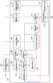
Fig. 1 is a block diagram illustrating a configuration of hardware of an image processing apparatus.
FIG. 2 is a software block diagram of an album creating application.
Fig. 3 illustrates a display screen provided by the album creating application.
Fig. 4 is a flowchart illustrating an automatic layout process.
Fig. 5 illustrates image analysis information.
Fig. 6A, 6B, and 6C illustrate the result of scene segmentation of an image data group.
Fig. 7 is a table illustrating the average values and standard deviations of the respective scenes.
Fig. 8A and 8B are tables illustrating the concept of the scoring axis (scoring axis).
Fig. 9A to 9I illustrate image data selection.
Fig. 10A to 10Q each illustrate a template group for image data layout.
Fig. 11 is a flowchart illustrating a process of sub-scene segmentation.
Fig. 12A to 12D are tables illustrating scene information on respective scenes.
Detailed Description
Various exemplary embodiments of the present invention will be described in detail below with reference to the accompanying drawings. It should be noted that the following exemplary embodiments are not intended to limit the scope of protection of the present invention, and each combination of features described in the following exemplary embodiments is not always necessary for the technical solution of the present invention. Similar components are given the same reference numerals, and the description thereof is omitted.
In the first exemplary embodiment, a process of causing an album creating application to operate on an image processing apparatus and generating a layout using an automatic layout function will be described.
Fig. 1 is a block diagram illustrating a configuration of hardware of an image processing apparatus. Examples of the image processing apparatus include a Personal Computer (PC) and a smartphone. In the present exemplary embodiment, a PC is used as the image processing apparatus. A Central Processing Unit (CPU)101 comprehensively controls the image processing apparatus 100, and, for example, reads a program stored on a Read Only Memory (ROM)102 onto a Random Access Memory (RAM)103 and executes the program to realize the operation of the present exemplary embodiment. Although a single CPU is illustrated in fig. 1, a plurality of CPUs may be used. The ROM102 is a general-purpose ROM, and stores, for example, a program to be executed by the CPU 101. The RAM 103 is a general-purpose RAM, and is used as, for example, a work memory for temporarily storing various types of information when the CPU 101 executes a program. A Hard Disk Drive (HDD)104 is a storage medium (storage unit) for storing a database including image files and processing results such as image analysis, templates used by the album creating application, and the like.
The display 105 displays a User Interface (UI) and an electronic album of the present exemplary embodiment to the user as an image layout result. The keyboard 106 and pointing device 107 receive command operations from a user. The display 105 may include touch sensor functionality. For example, the user inputs the number of double page spreads of an album that the user desires to create on the UI displayed on the display 105 using the keyboard 106. For example, the user clicks a button on a UI displayed on the display 105 using the pointing device 107.
The data communication unit 108 performs communication with an external device via a wired network or a wireless network. The data communication unit 108 transmits data laid out by the automatic layout function to, for example, a printer or a server capable of communicating with the image processing apparatus 100. The data bus 109 connects the blocks illustrated in fig. 1 so that the blocks can communicate with each other.
The album creating application in the present exemplary embodiment is saved in the HDD104, and is started if the user double-clicks an icon of an application displayed on the display 105 using the pointing device 107, as described below.
FIG. 2 is a software block diagram of an album creating application. Program modules respectively corresponding to the components of the configuration illustrated in fig. 2 are included in the above-described album creating application. Then, the CPU 101 executes the program modules to function as components of the configuration illustrated in fig. 2. Hereinafter, the components illustrated in fig. 2 will be described as components that perform various types of processing. Further, fig. 2 particularly illustrates a software block diagram of the automatic layout processing unit 216 configured to execute the automatic layout function.
The album creation condition specifying unit 201 determines an album creation condition according to a UI operation by the user using the pointing device 107 to be described below, and outputs the determined album creation condition to the automatic layout processing unit 216.
The image acquisition unit 202 acquires the image data group specified by the album creation condition specifying unit 201 from the HDD 104. The image conversion unit 203 converts image data for subsequent processing into image data having a desired number of pixels and color information. In the present exemplary embodiment, the image data is converted into analysis image data having a short side of 420 pixels and standard red, green, blue (sRGB) color information. The image analysis unit 204 performs feature amount acquisition, face detection, facial expression recognition, person recognition, and object recognition, which will be described below, from the analysis image data. Further, the image analysis unit 204 performs acquisition of data accompanying the image data acquired from the HDD104, for example, acquisition of image capturing date/time (time information) from exchangeable image file format (Exif) information. The plurality of images are segmented into image groups using temporal information, which will be described below. The image classification unit 205 performs scene segmentation and scene classification, which will be described below, on the image data group using image capturing date/time information, the number of captured images, detected face information, and the like. The term "scene" refers to an image-taking scene such as a travel, a usual scene, or a wedding. In the present exemplary embodiment, the plurality of images are divided into the plurality of image groups based on the time information. At this time, a plurality of images captured within one time block are included in the same image group, and thus the plurality of images included in the same image group are regarded as images captured in the same or similar image capturing scenes.
The image scoring unit 207 scores the respective image data so that an image suitable for the layout is given a high score. The image scoring unit 207 scores using the image analysis result information from the image analysis unit 204 and the classification information from the image classification unit 205. This will be described below.
The user information input unit 206 inputs an Identification (ID) (identification information) of the subject person specified by the album creation condition specifying unit 201 to the image scoring unit 207. The image scoring unit 207 is configured to give a higher score to the image data containing the subject person ID input from the user information input unit 206. Further, the user information input unit 206 inputs the priority mode specified by the album creation condition specifying unit 201 to the image scoring unit 207. The image scoring unit 207 is configured to add a higher score to image data containing at least one or more objects input from the user information input unit 206.
The two-page-spread allocation unit 209 divides a plurality of images into a plurality of image groups and allocates the plurality of divided image groups to a plurality of two-page spreads of the album, respectively. The double-page expansion number input unit 208 inputs the number of double-page expansions of the album specified by the album creating condition specifying unit 201 and the priority mode specified by the user to the double-page expansion allocating unit 209. The number of double page spreads of the album corresponds to the number of one or more templates in which a plurality of images are to be arranged.
The two-page spread allocation unit 209 divides a plurality of images into a plurality of image groups based on the input two-page spread number, and allocates some or all of the image groups to the two-page spread. Further, the two-page-spread allocation unit 209 divides or combines a plurality of image groups so that the number of image groups corresponds to the number of two-page spreads. In the present exemplary embodiment, the division of a plurality of image groups is also referred to as scene division, and the combination of a plurality of image groups is also referred to as scene combination. Further, in the present exemplary embodiment, the two-page extension allocating unit 209 divides or combines (scene division or scene combination) a plurality of image groups according to a priority mode specified by the user.
The image selecting unit 210 selects an image corresponding to the number of time slots specified by the album creating condition specifying unit 201 from each of the image groups respectively assigned to the two-page spread by the two-page spread assigning unit 209 based on the score given by the image scoring unit 207.
The image layout unit 212 determines the image data layout, for example, a time slot for laying out an image and an area of the image to be displayed in the time slot. The template input unit 211 inputs a plurality of templates corresponding to the template information specified by the album creation condition specifying unit 201 to the image layout unit 212. The image layout unit 212 selects a template suitable for the image selected by the image selection unit 210 from among the plurality of templates input by the template input unit 211 to determine the layout of the selected image. The layout information output unit 215 outputs layout information for display on the display 105 according to the layout of the selected image determined by the layout image unit 212. The layout information is, for example, bitmap data in which the image data of the image selected by the image selecting unit 210 is laid out on the selected template.
The image correction unit 214 performs various types of correction processing such as dodging correction (luminance correction), red-eye correction, and contrast correction. The image correction condition input unit 213 inputs an on/off (on/off) condition for image correction specified by the album creation condition specifying unit 201 to the image correction unit 214. The image correction unit 214 performs correction on the image data if the image correction condition is on. On the other hand, if the image correction condition is off, the image correction unit 214 does not perform correction on the image data. The image correction unit 214 performs correction on the image data input from the image conversion unit 203 based on whether the correction condition is on or off. The number of pixels of the image data input from the image conversion unit 203 to the image correction unit 214 may be changed according to the size of the layout determined by the image layout unit 212.
When the album creating application is installed in the image processing apparatus 100, a start icon is displayed on a top screen (desktop) of an Operating System (OS) running on the image processing apparatus 100. If the user double-clicks the start icon displayed on the display 105 with the pointing device 107, the program of the album creating application saved in the HDD104 is loaded on the ROM 102. The program loaded on the ROM102 is read into the RAM 103 and executed by the CPU 101 to start the album creating application.
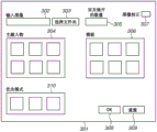
Fig. 3 illustrates an example of a display screen 301 provided by the album creating application. The display screen 301 is displayed on the display 105. The user sets an album creating condition to be described below via the display screen 301, and the album creating condition specifying unit 201 acquires details of the user setting.
The path box 302 on the display screen 301 displays storage locations (paths) of a plurality of images (for example, a plurality of image files) as album creation targets in the HDD 104. If the folder select button 303 is clicked by the user with the pointing device 107 to give an instruction, a folder selection screen is displayed. On the folder selection screen, folders set in the HDD104 are displayed in a tree configuration, and the user can select a folder containing an album creation target image with the pointing device 107. The folder path for the folder selected by the user is displayed in path box 302.
The subject person designation icon 304 is an icon in which the user designates a subject person, and a face image of the person is displayed as the subject person designation icon 304. A plurality of icons of different face images are arranged and displayed in the subject person designation icon 304, and the user can select an icon by clicking the icon with the pointing device 107. The double page spread number box 305 receives a setting of the double page spread number of the album from the user. The user may enter the quantity directly into the double page spread number box 305 via the keyboard 106 or from a list into the double page spread number box 305 using the pointing device 107.
The template designation icon 306 displays an explanatory image on a stylistic basis (popular, unique, etc.) of the template. A plurality of template icons are arranged and displayed in the template designation icon 306, and the user can select a template icon by clicking on the template icon with the pointing device 107. The check box 307 receives designation of the on/off condition of image correction from the user. The state in which the hook symbol is input in the check box 307 is a state in which the image correction is set to on, and the state in which the hook symbol is not input in the check box 307 is a state in which the image correction is set to off.
The priority mode designation icon 310 is an icon for designating a mode (subject of picture in the present exemplary embodiment) that the user desires to prioritize, and icons of characters, pets, and flowers are displayed. The user may select the priority mode designation icon 310 by clicking the priority mode designation icon 310 with the pointing device 107, and the priority mode designation icon 310 receives a user instruction regarding the type of important object. More specifically, the user can specify a person, a pet, or a flower as a subject type to be prioritized as a layout target by clicking the priority mode designation icon 310.
Further, in the present exemplary embodiment, a plurality of image groups into which a plurality of images are divided or combined so that the plurality of image groups correspond to the number of double page expansions. At this time, a plurality of image groups are divided or combined so that the subjects of the type designated with the priority mode designation icon 310 are included in the respective divided or combined image groups. More specifically, a plurality of image groups are divided or combined so that the divided or combined image groups are prevented from not including the priority subjects designated using the priority mode designation icon 310 and the priority subjects are included in the respective image groups. The details of which will be described below.
When the user presses the OK button 308, the album creation condition designating unit 201 acquires the setting content set on the display screen 301. The album creation condition specifying unit 201 outputs the acquired set contents to the automatic layout processing unit 216 of the album creating application. At this time, the path input to the path box 302 is sent to the image acquisition unit 202. The person ID of the subject person selected at the subject person designation icon 304 and the priority mode designated at the priority mode designation icon 310 are transmitted to the user information input unit 206, and also transmitted to the image scoring unit 207. The number of double page spreads input to the double page spread number box 305 and the priority mode designated at the priority mode designation icon 310 are sent to the double page spread number input unit 208, and also sent to the double page spread allocation unit 209.
The template information selected at the template designation icon 306 is transmitted to the template input unit 211. The designation of the on/off condition of the image correction at the check box 307 is sent to the image correction condition input unit 213. The reset button 309 on the display screen 301 is a button for resetting the setting information on the display screen 301.
Fig. 4 is a flowchart illustrating processing performed by the automatic layout processing unit 216 of the album creating application. For example, the CPU 101 reads a program stored on the HDD104 onto the ROM102 or the RAM 103 and executes the program to realize the flowchart illustrated in fig. 4. In the description of fig. 4, the CPU 101 executes an album creating application so that the components of the configuration illustrated in fig. 2 function and perform processing. The automatic layout process will be described below with reference to fig. 4.
In step S401, the image conversion unit 203 generates analysis image data. More specifically, the image conversion unit 203 identifies a plurality of image files stored in folders in the HDD104 and specified in the album creation condition specifying unit 201, and reads out the plurality of identified image files from the HDD104 to the RAM 103. Then, the image conversion unit 203 converts the image data of the read image file into analysis image data containing a desired number of pixels and color information. In the present exemplary embodiment, the image conversion unit 203 converts the image data into analysis image data having a short side of 420 pixels and containing sRGB color information.
In step S402, the image analysis unit 204 acquires image feature quantities. The image analysis unit 204 acquires the image capturing date/time from, for example, Exif information accompanying an image file as time information of an image contained in the image file read from the HDD 104. Further, the image analysis unit 204 acquires feature amounts from the analysis image data generated in step S401. Examples of the feature quantity include an in-focus (in-focus) level of a focus. In order to obtain the in-focus level of the focus, edge detection is performed. Sobel filters are well known edge detection methods. Edge detection is performed by a sobel filter, and the gradient of an edge is calculated by dividing the luminance difference between the start point and the end point of the edge by the distance between the start point and the end point. From the calculation of the average gradient of the image edges, an image with a large average gradient can be considered to be more focused than an image with a small average gradient. Then, if a plurality of thresholds of different values are set as the gradient, the resultant power evaluation value can be output by determining which threshold the gradient exceeds. In the present exemplary embodiment, two different thresholds are set in advance, and the degree of convergence is judged in three levels of "good", "normal", and "poor". For example, it is desirable that a focus gradient for an album is judged as "good", an allowable focus gradient is judged as "normal", an unallowable focus gradient is judged as "bad", and a threshold value is set in advance. For example, the setting of the threshold may be provided by a creator of the album creating application or the like, or the threshold may be set on a user interface.
In step S403, the image analysis unit 204 performs face detection on the analysis image data generated in step S401. A well-known method may be used in the face detection process, and, for example, adaptive boosting (AdaBoost) in which a strong classifier is generated by a plurality of weak classifiers is used. In the present exemplary embodiment, a strong classifier generated by AdaBoost detects a face image of a person (subject). The image analysis unit 204 extracts a face image, and acquires upper-left and lower-right coordinate values of the position of the detected face image. With these two coordinates, the image analysis unit 204 can acquire the position and size of the face image.
In step S404, the image analysis unit 204 performs person recognition by comparing the face image detected in step S403 in the processing target image based on the analysis image data with the representative face images held for the respective person IDs in the face dictionary database. The image analysis unit 204 identifies, from the plurality of representative face images, a representative face image having the highest similarity not lower than a threshold value with a face image in the processing target image. Then, the person ID corresponding to the identified representative face image is determined as the ID of the face image in the processing target image. If the degree of similarity of each of the plurality of representative face images to the face image in the processing target image is lower than the threshold value, the image analysis unit 204 registers the face image in the processing target image as a new representative face image associated with a new person ID in the face dictionary database.
In step S405, the image analysis unit 204 performs object recognition on the analysis image data generated in step S401. In the object recognition process, a known method can be used. In the present exemplary embodiment, the object is identified by a discriminator generated by deep learning. The image analysis unit 204 may acquire the type of the object, for example, a pet (dog or cat), a flower, food, a building, or a stationary item by recognizing the image of the object.
The image analysis unit 204 distinguishes the image analysis information acquired in steps S402 to S405 for each ID identifying each image as illustrated in fig. 5, and stores the image analysis information in a storage area such as the ROM 102. For example, as illustrated in fig. 5, the image capturing date/time information and the focus determination result acquired in step S402, the number of detected face images and the position information on the face images acquired in step S403, and the type of object identified in step S405 are stored in the form of a table. The position information on the face image is discriminated and stored for each person ID acquired in step S404. Further, if a plurality of types of objects are recognized from a single image, all of the objects of the plurality of types are stored in a row corresponding to the single image in the table illustrated in fig. 5.
In step S406, it is determined whether the execution of steps S401 to S405 on all the images stored in the designated folder in the HDD104 designated by the album creation condition designating unit 201 is completed. If it is determined that the execution of steps S401 to S405 for all the stored images is not completed (no in step S406), step S401 and the subsequent steps are repeatedly performed. On the other hand, if it is determined that the execution of steps S401 to S405 for all the stored images is completed (yes in step S406), the processing proceeds to step S407. In this way, steps S401 to S405 are repeatedly performed for all the images stored in the designated folder, creating a table containing information on the respective images, as illustrated in fig. 5.
In step S407, the image classification unit 205 performs scene division for dividing all the images stored in the specified folder into a plurality of image groups based on the time information. In the division, the number of image groups does not necessarily coincide with the number of two-page spreads, and the division is a provisional division process for the final division process. The image classification unit 205 calculates a difference in image capturing time between the plurality of images stored in the designated folder based on the image capturing date/time information (time information) acquired in step S402. Then, the image classification unit 205 divides the plurality of images stored in the designated folder into a plurality of image groups (a plurality of scenes) based on the difference in image capturing time.
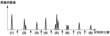
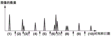
In the present exemplary embodiment, for example, the image sorting unit 205 sorts a plurality of images stored in a specified folder in order of image capturing date/time, and creates a list containing image names (e.g., image file names) and image capturing dates/times in the RAM 103. At this time, if the image capturing dates corresponding to two consecutive images in the list are not consecutive, the image sorting unit 205 assigns the two images to different image groups. Alternatively, the segmentation into image groups may be done based on any other criterion (criterion). For example, even if the image capturing dates corresponding to two images are consecutive, the two consecutive images in the list may be assigned to different image groups. In this case, for example, if the difference in image capturing time between two consecutive images in the list is 16 hours or more, the two images are assigned to different image groups. Further, even if the difference in image capturing time between two consecutive images in the list is less than 16 hours, if the time difference between the first image capturing time and the last image capturing time in each of two consecutive dates is less than 4 hours, the plurality of images captured on the two dates are divided into different image groups on a date-by-date basis. On the other hand, if the time difference between the first image capturing time and the last image capturing time in each of two consecutive dates is not less than 4 hours, the division is performed on a date basis when the number of images captured on each date is less than 50, and is not performed when the number of images captured on each date is 50 or more. Fig. 6A illustrates an example of a result of dividing (scene-dividing) a plurality of images contained in a designated folder into a plurality of image groups by the above-described scene-dividing method. In fig. 6A, the numbers (1) to (8) indicate each image group (scene), the vertical axis indicates the number of images of each image group, and the horizontal axis indicates the image capturing date/time of each image group.
In step S408, the image classification unit 205 performs scene classification. In the present exemplary embodiment, for example, the image classification unit 205 classifies the divided image data subjected to the scene division into one of a travel, an ordinary scene, and a ceremonial image capturing scene. Before the process illustrated in fig. 4 is started, the user collects and specifies a plurality of image data determined as an image data of a travel, a general scene, or a ceremony image capturing scene. The image classification unit 205 compares the image associated with each scene by the designation with the images included in the image group divided in step S407 to identify the type of the image capturing scene corresponding to each image group. The image capturing scene recognition processing will be described below.
First, the designation of image data corresponding to an image capturing scene by a user will be described below. For example, the album creation condition designating unit 201 receives designation of a plurality of image data of the image data determined as the travel scene by the user on a user interface screen (not illustrated). Further, the image analysis unit 204 acquires feature amounts of a plurality of image data. Examples of the feature amount to be acquired include an image capturing period, the number of captured images, and the number of persons to be captured. The image capturing period is a time difference between the first image capturing and the last image capturing of the plurality of specified image data as described above. The number of captured images is the number of captured images of the plurality of image data. The number of persons photographed is the number of faces photographed. As a result, the image capturing period, the number of captured images, and the number of persons captured of one image data group of a plurality of image data including the image data determined as the travel scene by the user are acquired as the feature quantities.
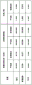
Then, the image analysis unit 204 further performs the acquisition of the image capturing period, the number of captured images, and the number of captured persons as the feature amounts as described above for the other image data group specified by the user. Then, the image analysis unit 204 calculates the average value and the standard deviation of the image capturing period, the average value and the standard deviation of the number of captured images, and the average value and the standard deviation of the number of captured persons, based on the feature amounts acquired from the plurality of image data groups. Fig. 7 illustrates the calculated average value and the calculated standard deviation, and the image analysis unit 204 stores these values in a storage area of the ROM102 in advance. Alternatively, these values may be embedded in advance in the program of the album creating application.
The process executed in step S408 of fig. 4 is described again here. After the album creating application is started, the image classification unit 205 calculates scores of each feature amount of the image capturing period, the number of captured images, and the number of persons captured for each section obtained by the scene division performed on the image data group specified by the user at the path box 302 in step S407. The image classification unit 205 calculates scores of the image capturing period, the number of captured images, and the number of persons captured for each section according to equation (1) using the average value and standard deviation of each scene illustrated in fig. 7.
Score 50- |10 × (mean-characteristic amount)/standard deviation | … (1)
Further, an average score of the scores is calculated using equation (2).
Average score (score of image capturing period + score of number of captured images + score of number of persons capturing)/number of feature amount items … (2)
As a result of the calculation, an average score is calculated for each of the travel scene, the ordinary scene, and the ceremony scene of the image data with respect to each of the partitions. Then, the image classification unit 205 classifies the image data of the partition into a scene corresponding to the highest score. If the scenes are given the same score, the image data is classified according to a predetermined order of priority of the scenes. For example, in the present exemplary embodiment, the priority order is determined as general scene > ceremonial > travel, and the highest priority is given to general scenes. For example, regarding the image group 5 in fig. 6A in which scene segmentation is performed, the image capturing period is 36 hours, the number of captured images is 300, and the number of captured persons is 1.7. The average scores for the travel scenario, the general scenario, and the ceremonial scenario calculated using equations (1) and (2) above were 45.32, 18.38, and-29.92, respectively. Thus, the image group 5 is classified as a travel scene. The image classification unit 205 provides the classified scenes with scene IDs to make the scenes recognizable, and manages the scenes.
In step S409, it is determined whether the execution of scene classification for all scenes divided in step S407 in step S408 is completed. If it is determined that the execution of scene classification for all the divided scenes in step S408 is not completed (no in step S409), step S408 and subsequent steps are repeatedly performed. On the other hand, if it is determined that the execution of scene classification for all the divided scenes in step S408 is completed (yes in step S409), the processing proceeds to step S410.
In step S410, the image scoring unit 207 performs subject person setting. The subject person setting is performed on a plurality of images contained in a folder designated by a user, and is performed using one of two setting methods, an automatic setting method and a manual setting method. In the manual setting method, the user selects a subject person by clicking an icon of a person displayed as the subject person designation icon 304 in fig. 3 with the pointing device 107. Further, the automatic setting method is performed as follows. The image scoring unit 207 may acquire the number of times the personal ID appears in the image data group, the number of times the personal ID appears in each scene, the number of scenes in which the personal ID appears, and the like from the result of the person recognition performed in step S404 and the result of the scene segmentation performed in step S406. The image scoring unit 207 automatically sets the subject person instead of the user specification according to these pieces of information. In the present exemplary embodiment, if there are a plurality of scenes, the image scoring unit 207 sets the personal ID that appears most frequently in the plurality of scenes, and if there is only a single scene, the image scoring unit 207 sets the personal ID that appears most frequently in the single scene.
Further, in the case where the subject person designation icon 304 is designated by the user, the user information input unit 206 transmits the designated person ID to the image scoring unit 207. In the case where the person ID is designated by the user, the image scoring unit 207 sets the person ID designated by the user as the subject person ID instead of the automatically set subject person ID as described above. This setting is called "manual setting".
In step S411, the image scoring unit 207 performs priority mode setting. The priority mode setting is performed for a plurality of images contained in a folder designated by a user, and one of two setting methods of an automatic setting method and a manual setting method is used. In the manual setting method, the user selects a desired priority mode (type of subject to be prioritized) by clicking a character icon, a pet icon, or a flower icon displayed as the priority mode designation icon 310 in fig. 3 with the pointing device 107. The automatic setting method is performed as follows. The image scoring unit 207 acquires the number of times of appearance in a plurality of images for each object type based on the result of the object recognition performed in step S405. Similarly, the image scoring unit 207 may acquire the number of times of occurrence in each image group (scene) for each object type. Further, the image scoring unit 207 may acquire, for each object type, the number of times the scene in which the object of the object type appears. The image scoring unit 207 automatically sets a priority mode according to these pieces of information, instead of being specified by the user. In the present exemplary embodiment, if a plurality of image groups (scenes) exist, the image scoring unit 207 sets a mode that prioritizes the object type that appears most frequently in the plurality of image groups. In addition, if only a single image group (scene) exists, the image scoring unit 207 sets a mode that prioritizes the object type that appears most frequently in the single image group.
In step S412, the image scoring unit 207 performs score calculation. The score calculation is to give scores (scores) evaluated for respective image data from viewpoints described below, and is referred to when selecting image data for layout as will be described below. Fig. 10A to 10Q illustrate template groups for image data layout. The plurality of templates included in the template group each correspond to a two-page spread. The template 1001 is a single template, and there is a main slot 1002 and sub slots 1003 and 1004. The main slot 1002 is a main slot (a frame in which an image is to be arranged) in the template 1001, and the size of the main slot 1002 is larger than the sizes of the sub slots 1003 and 1004. The image scoring unit 207 gives scores of both the main time slot and the sub time slot to each image data.
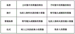
Fig. 8A illustrates the features of images to be used in the album of each image capturing scene of the travel scene, the ordinary scene, and the ceremony scene with respect to the main time slot and the sub time slot. Before the process illustrated in fig. 4 is started, the user collects and specifies in advance a plurality of image data determined to match the features of the main time slot and the sub time slot suitable for each scene illustrated in fig. 8A. The image scoring unit 207 compares the images associated with the main slot and the sub slot by the designation with the images included in the image group divided in step S407. By comparison, the matching degree of each image with respect to the main time slot and the sub time slot is calculated. The score calculation process will be described below.
First, the designation made in advance by the user will be described below. For example, the album creation condition specifying unit 201 receives, on a user interface screen (not illustrated), a specification by the user of a plurality of image data of the main time slot (or suitable for the sub time slot) determined to be suitable for the travel scene. The image analysis unit 204 acquires the number of faces, the face positions, and the face sizes in each of the designated image data as feature amounts. As a result, for example, the number of faces, the face positions, and the face sizes in each of the plurality of image data that the user has determined to be suitable for the main time slot (or suitable for the sub time slot) of the travel scene are acquired as the feature amounts. Then, the image analysis unit 204 calculates the average and standard deviation of the number of faces, the average and standard deviation of the positions of the faces, and the average and standard deviation of the sizes of the faces. The image analysis unit 204 calculates the average value and the standard deviation as statistical values of the respective feature amounts as described above for the respective slot types (main slot and sub slot) of the respective scenes. The image analysis unit 204 stores these values in a storage area such as the ROM102 in advance. Alternatively, a value may be embedded in advance in a program of the album creating application.
The image scoring unit 207 may acquire information about the scene to which each image data belongs from the result of the scene classification performed in step S407. The image scoring unit 207 calculates a score according to the following expression (3) using the average value and standard deviation corresponding to the scene of the image data of interest calculated in advance, and the feature amounts of the number of faces, the face position, and the face size of the subject person ID of the image data of interest.
Score 50- |10 × (mean-characteristic amount)/standard deviation | … (3)
Further, the average score is calculated according to equation (4).
Number of feature amount items … (4) is the average score (score of number of faces + score of face position + score of face size)/number of feature amount items
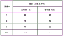
The image scoring unit 207 performs score calculation on both the main time slot and the sub time slot. An image to be used in the album is desirably in a focused state so that a predetermined score can be added to the image data of the image ID having the feature amount of the focus of "good" in fig. 5. Fig. 8B illustrates an example of a score result obtained by the above-described score calculation, and the score calculation is performed for the main slot and the sub slot for each image ID.
In this case, in the present exemplary embodiment, as illustrated in fig. 8A, conditions suitable for the main slot and the sub slot are determined for each scene, and the image data judged to be suitable for the main slot and the sub slot is specified in advance by the user. The image analysis unit 204 acquires feature amounts of the number of faces, the position of the face, and the size of the face for image data specified by the user, and calculates the average value and standard deviation of the respective feature amounts. Then, after the album creating application is started, if the automatic layout processing illustrated in fig. 4 is started, score calculation (similarity) is performed which indicates how close each image data as a target of the automatic layout processing (subjected to scene classification) is to a user determination criterion such as suitability for a main slot. For example, in fig. 8B, the image ID 1 is given 20 points for the main slot, and the image ID 2 is given 45 points for the main slot. This indicates that the image ID 2 is closer to the user judgment reference for the main slot.
Referring back to fig. 4, in step S413, the image scoring unit 207 determines whether the execution of the image score calculation for all the images contained in the folder designated by the user in step S412 is completed. If the image scoring unit 207 determines that the execution of the image scoring calculation in step S412 for all the images contained in the folder designated by the user has not been completed (no in step S413), step S412 and the subsequent steps are repeatedly performed. On the other hand, if the image scoring unit 207 determines that the execution of the image scoring calculation in step S412 for all the images contained in the folder designated by the user is completed (yes in step S413), the processing proceeds to step S414.
In the present exemplary embodiment, the image layout unit 212 lays out images included in a plurality of scenes on a plurality of templates (a plurality of two-page spreads) respectively corresponding to the plurality of scenes. Therefore, the number of the plurality of scenes needs to be the same as the number of the plurality of templates (the number of predetermined two-page spreads).
Then, in step S414, the two-page-spread allocation unit 209 determines whether the number of scenes divided (the number of divided image groups) in step S407 is the same as the number of two-page spreads of the album input from the two-page-spread number input unit 208. If the two-page spread allocation unit 209 determines that the number of divided scenes is not the same as the number of input two-page spreads (no in step S414), the processing proceeds to step S415. On the other hand, if the two-page spread allocation unit 209 determines that the number of divided scenes is the same as the number of input two-page spreads (yes in step S414), the processing proceeds to step S418. For example, if the number of divided scenes is 8 and the number input from the two-page spread number input unit 208 is also 8, as illustrated in fig. 6A, the process proceeds to step S418.
In step S415, the double-page-spread allocation unit 209 determines whether the number of scenes divided in step S407 is smaller than the number of double-page spreads (the number of templates used in the album) input from the double-page-spread number input unit 208. If the two-page spread allocation unit 209 determines that the number of divided scenes is not less than (greater than) the number of two-page spreads (no in step S415), the processing proceeds to step S417. On the other hand, if the two-page spread allocation unit 209 determines that the number of divided scenes is smaller than the number of two-page spreads (yes in step S415), the processing proceeds to step S416. As illustrated in fig. 6A, if the number of divided scenes is 8 and the number input from the two-page spread number input unit 208 is 10, the process proceeds to step S416. In steps S416 and S417, the two-page-spread allocation unit 209 performs processing on the plurality of image groups subjected to temporary division in step S407 illustrated in fig. 6A to change the number of divisions (the number of scenes) so that the number of scenes becomes the same as the number of two-page spreads. Details of the processing will be described below.
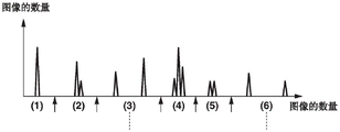
In step S416, the two-page spread allocation unit 209 performs sub-scene division. Sub-scene division refers to further division of the divided scenes when the number of divided scenes is less than the number of double-page spreads of the album. The case where the number of divided scenes in fig. 6A is 8 and the number of double page developments of the designated album is 10 will be described below. Fig. 6B illustrates the result of performing sub-scene segmentation on the image group illustrated in fig. 6A. The division is performed at the portion designated by the dotted arrow to increase the number of divisions to ten.
The reference of the segmentation will be described below. The partitions in fig. 6A are searched to find a partition having a large number of images. In the present exemplary embodiment, it is determined that the number of segmentations is increased from eight to ten at two portions having a large number of images. In fig. 6A, the image group 5 has the largest number of images, and the image groups 1 and 2 have the second largest number of images. The image groups 1 and 2 have the same number of images, but the image group 2 has a large time difference between the first image and the last image, so that the image group 2 is determined as a division target, and the image group 5 and the image group 2 are divided, respectively.
First, the segmentation of the image group 2 will be described below. The image group 2 has two peak values of the number of images, and the image capturing dates of the two peak values are different. Therefore, the image group 2 is divided at a portion corresponding to the portion designated by the broken-line arrow in fig. 6B. Next, the segmentation of the image group 5 will be described below. The image group 5 has three peak image numbers and is an image group captured for three consecutive days. The image capturing date is changed in two portions, but in order to reduce the difference in the number of divided images, the image group 5 is divided at a portion designated by a broken-line arrow in fig. 6B. As described above, the number of divisions increases from eight to ten. Although the image group is divided at a portion where the image capturing date is changed in the present exemplary embodiment, if a portion where the number of images is large is a single date, the division may be performed at a portion having the largest time difference of the single date.
In step S417, the two-page spread allocation unit 209 performs scene combination. Scene combination refers to a combination of divided scenes in the case where the number of divided scenes is larger than the number of double-page developments of the album. Fig. 6C illustrates a result of performing scene combination on the image group illustrated in fig. 6A. The combination is performed at the portion designated by the broken line to reduce the number of divisions to six.
The reference of the combination will be described below. The partitions in fig. 6A are searched to find partitions with a small number of images. In the present exemplary embodiment, it is determined to reduce the number of partitions from eight to six at two portions having a small number of images. In fig. 6A, image group 8 has the least number of images, followed by image groups 3 and 7. The image groups 3 and 7 have the same number of images. The image group 8 adjacent to the image group 7 is a combination target, so that the image group 3 is determined as a combination target. As a result, the image groups 8 and 3 are combined, respectively.
First, the combination of the image group 3 will be described below. The time difference between the image group 3 and the image group before the image group 3 (i.e., the group 2) is compared with the time difference between the image group 3 and the image group after the image group 3 (i.e., the group 4), and the time difference between the image group 3 and the image group 4 is small. Thus, image group 3 is combined with image group 4 as illustrated by the dotted line portion in fig. 6C. Next, the combination of the image group 8 will be described below. There are no image groups after image group 8, so image group 8 is combined with the image group before image group 8 (i.e., image group 7), as illustrated by the dashed line portion in fig. 6C.
In step S418, the double page spread allocation unit 209 performs double page spread allocation. As a result of steps S414 to S417, the number of divided scenes is the same as the number of designated two-page spreads. The two-page spread allocation unit 209 allocates the plurality of image groups to the two-page spread, respectively, to prevent the plurality of image groups from being mixed on any two-page spread. More specifically, the two-page spread allocation unit 209 allocates a plurality of image groups in the order of image capturing date/time, starting with the allocation of the top image group to the top two-page spread.
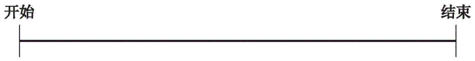
In step S419, the image selection unit 210 selects an image to be laid out on a specific two-page spread from the image group corresponding to the specific two-page spread. An example of selecting four image data from the image group assigned to the two-page spread will be described below with reference to fig. 9A to 9I.
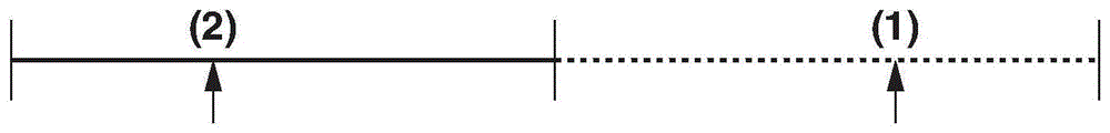
The section from the start to the end in fig. 9A represents the time difference (image capturing period of the division) between the image capturing date/time of the first image data and the image capturing date/time of the last image data assigned to the division of the two-page spread. A method of selecting the first image will be described below with reference to fig. 9B. The template includes a primary time slot 1002. Accordingly, the image data of the main slot is selected as the first image. From among a plurality of image data corresponding to the image capturing periods of the partitions illustrated in fig. 9B, the image data given in step S412 having the highest score for the master slot is selected. For the second and subsequent images, the image data of the sub-slot is selected.
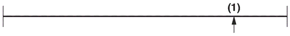
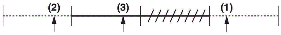
In the present exemplary embodiment, the images are selected in such a manner as to avoid concentration on a part of the image capturing period of the division. A method of further dividing the image capturing period of the division in the present exemplary embodiment will be described below. As illustrated in fig. 9C, the image capturing period of the divided region is divided into two divided regions. Next, as illustrated in fig. 9D, the second image is selected from the image capturing period designated by the solid line from which the first image is not selected. From among a plurality of image data corresponding to the image capturing period designated by the solid line in fig. 9D, image data having the highest score for the sub-slot is selected.
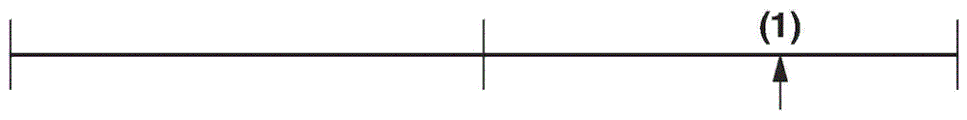
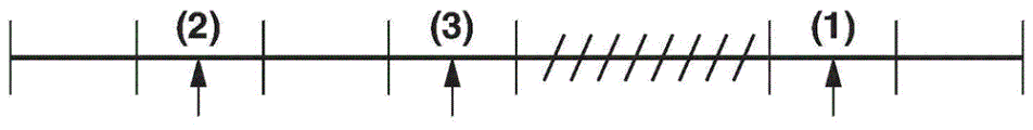
Next, as illustrated in fig. 9E, the image capturing period of each partition in fig. 9D is divided into two partitions. Then, as illustrated in fig. 9F, from among a plurality of image data corresponding to the image capturing periods designated by the solid lines and from which the first image and the second image are not selected, the image data having the highest score for the sub-slot is selected as the third image.
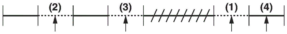
A case where no image data is selectable because there is no image data corresponding to the image capturing period of the image data selection target will be described below by describing selection of the fourth image as an example. Fig. 9G illustrates an example in which there is no image data corresponding to an image capturing period marked with oblique lines and from which image data is not selected when the fourth image is selected from the image capturing period. In this case, as illustrated in fig. 9H, the image capturing period of each partition is divided into two partitions. Next, as illustrated in fig. 9I, from among a plurality of image data corresponding to the image capturing periods designated by the solid lines and from which the first to third images are not selected, the image data having the highest score for the sub-slot is selected as the fourth image.
Referring back to fig. 4, in step S420, the image layout unit 212 determines an image layout. An example in which the template input unit 211 inputs the templates in fig. 10A to 10Q to the two-page spread according to the specified template information will be described below.
In the present exemplary embodiment, the number of time slots in the input template is set to three. The directions of the selected three images arranged according to the image capturing date/time (longitudinal or lateral) are as specified by the template in fig. 10Q. In the present exemplary embodiment, the image data 1005 is for the main slot, and the image data 1006 and the image data 1007 are for the sub slot. In the present exemplary embodiment, the image data of the older image capturing date/time is laid out at the upper left of the template, and the image of the newer image capturing date/time is laid out at the lower right of the template. In the case of the template in fig. 10Q, the image data 1005 of the main slot has the latest image capturing date/time, and therefore, the templates in fig. 10I to 10L are determined as candidates. Further, the image data 1006, which is an older one of the images for the sub-slot, is a landscape image, and the image data 1007, which is a newer one of the images for the sub-slot, is a portrait image. Therefore, the template in fig. 10J is determined as the most suitable template of the selected three image data to determine the layout. In step S420, an image to be laid out, a template of the image to be laid out, and a time slot of the template of the image to be laid out are determined.
In step S421, the image correction unit 214 performs image correction. The image correction unit 214 performs image correction if information indicating that the image is corrected on is input from the image correction condition input unit 213. For example, in the image correction, a dodging correction (luminance correction), a red-eye correction, and a contrast correction are performed. On the other hand, if information indicating that the image correction is off is input from the image correction condition input unit 213, the image correction unit 214 does not perform the image correction. Image correction may be performed on size-converted image data having, for example, a short side of 1200 pixels and an sRGB color space.
In step S422, the layout information output unit 215 creates layout information. The image layout unit 212 lays out the image data on which the image correction is performed in step S421 on each time slot of the template determined in step S420. At this time, the image layout unit 212 changes the size of the image data to be laid out according to the size information on the time slot, and then lays out the resultant image data. Then, the layout information output unit 215 generates bitmap data in which the image data is laid out on the template as an output image.
In step S423, it is determined whether the execution of steps S419 to S422 for all the two-page spread is completed. If it is determined that the execution of steps S419 to S422 for all the two-page spread is not complete (no in step S423), the processing in step S419 and the subsequent steps is repeatedly performed. On the other hand, if it is determined that the execution of steps S419 to S422 for all the two-page spread is completed (yes in step S423), the automatic layout processing illustrated in fig. 4 is completed.
If the automatic layout processing in fig. 4 is completed, the layout information output unit 215 outputs the bitmap data (output image) generated in step S422 and having the image laid out on the template to the display 105, and the display 105 displays the bitmap data.
Details of the sub-scene segmentation performed in step S416 of fig. 4 will be described below. Fig. 11 is a flowchart illustrating details of the sub-scene division process of the double-page-spread allocation unit 209 of the album creating application in the present exemplary embodiment. The sub-scene division process will be described below with reference to fig. 11.
In step S1101, the two-page spread allocation unit 209 acquires the total number of images as candidates for layout on the album. For example, information on the total number of images stored in a specified folder in the HDD104 specified by the album creation condition specifying unit 201 is acquired.
In step S1102, the two-page spread allocation unit 209 sets an initial value of the partition number N of the sub-scene. For example, the number of double page expansions of the album input from the double page expansion input unit 208 is set to an initial value N. However, there is a case where the number of partitions N of the sub-scene is larger than the number of two-page spread as described below in the description of step S1117.
In step S1103, the two-page spread allocation unit 209 performs temporary sub-scene division so that the number of sub-scenes becomes the same as the number of partitions N. As for the method of provisional sub-scene segmentation, as described above in the description of step S416 of fig. 4, a group of images having a large number of images is segmented using a date as a separator. If there are two image groups having the same number of images, a time difference between the image capturing date/time of the first image and the image capturing date/time of the last image is calculated for each of the two image groups, and provisional segmentation is performed on one image group having a larger time difference than the other image group.
In step S1104, the two-page spread allocation unit 209 calculates scene information including information on each of the currently divided sub-scenes, and stores the calculated scene information in, for example, the RAM 103.
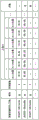
Fig. 12A illustrates an example of scene information in a case where the partition number N of the sub-scene is updated from 10, which is the number of two-page developments as an initial value, to N ═ 14, and the provisional division is performed by the processing performed in step S1117 described below. The scene ID is a unique ID (corresponding to numbers from 1 to 14 in this example) of each divided sub-scene.
The scene information in fig. 12A includes the number of images in each sub-scene, the number of objects, the importance, and the image capturing period in each sub-scene. Further, the scene information also includes a time difference between the last photographing time in the sub-scene of the next scene ID in the list illustrated in fig. 12A and the first photographing time in the sub-scene. The number of images indicates the number of images included in each of the divided sub-scenes. The number of objects represents the total number of objects in the image contained in each scene. The number of objects corresponds to, for example, the number of faces detected by the image analysis unit 204 in step S403 and the number of objects identified for the respective object types in step S405. The "time period" included in the scene information is an image capturing period of images included in each divided sub-scene of the image group (scene), and represents a time difference between the image capturing date/time of the first image and the image capturing date/time of the last image when the image data is arranged in the order of the image capturing times. The "time difference" included in the scene information is a time difference between the divided sub-scenes, and represents an image capturing interval between an image capturing date/time of the last image of the target scene and an image capturing date/time of the first image of the next scene when the image data are arranged in the order of image capturing times. The "deletion target" and "scene combination ID" in fig. 12A will be described below.
In step S1105, the two-page spread allocation unit 209 determines whether the total number of images acquired in step S1101 is not less than a predetermined number. If the total number of images is not less than the predetermined number (yes in step S1105), the processing proceeds to step S1106. On the other hand, if the total number of images is less than the predetermined number (no in step S1105), the processing proceeds to step S1107.
In step S1106, the two-page spread assigning unit 209 sets an importance degree calculating method in such a manner that the object (person, pet, or flower) in the scene information is weighted in the calculation of the importance degree of each sub-scene. On the other hand, in step S1107, the two-page spread allocation unit 209 sets the importance degree calculation method in such a manner that the items regarding the distinction are weighted in the calculation of the importance degree of each sub-scene. Hereinafter, the importance degree calculation methods set in steps S1106 and S1107 are sometimes referred to as calculation methods a and B, respectively. In step S1108, the two-page spread allocation unit 209 calculates the importance of each sub-scene based on the importance calculation method set in step S1106 or S1107, and stores the calculated importance in the RAM 103 as "importance" of the scene information in fig. 12A. The sub-scene with low importance calculated in step S1108 is more likely to be a deletion target or a combination target in the processing in step S1109 and subsequent steps described below.
The importance calculating method setting process and the importance calculating process using the set calculating method in steps S1106 to S1108 will be described in detail below.
The calculation of the calculation method a set in step S1106 is represented by the following formula (5).
(scene importance) — (days of time difference) × 24+ (time of time difference) + (number of images in the scene containing an object) × α + (number of images in the scene not containing an object) × β … (5)
The value α is greater than the value β, and the desired value is set to the value α. For example, in the case where α is 10 and β is 1, the "number of images including an object" contributes to the scene importance by 10 times the "number of images not including an object".
The calculation of the calculation method B set in step S1107 is represented by the following formula (6).
(scene importance) × 24+ (time of time difference) + number of images in scene … (6)
As described above, in any one of the calculation methods a and B, the two-page spread allocation unit 209 calculates the scene importance degree based on the time difference between sub-scenes adjacent in the time order of the image capturing date/time and the number of images in the sub-scenes. More specifically, the larger the time difference between adjacent sub-scenes, the higher the possibility of facing an image capturing scene different from the adjacent sub-scenes, and the scene importance becomes high. Further, the larger the number of images contained in the sub-scene is, the more important the image capturing scene is for the image capturing person, so that the importance becomes high. On the other hand, the smaller the number of images in a sub-scene, and the smaller the time difference between adjacent sub-scenes, the lower the scene importance.
The calculation method a represented by equation (5) is different from the calculation method B represented by equation (6) in that whether or not an object is contained in an image is considered. Therefore, in the calculation method a, in addition to the "time difference" (time difference between scenes) and the "number of images" included in the scene information in fig. 12A, the "whether or not an object is included in an image" is reflected in the scene importance.
On the other hand, in the calculation method B, "time difference" (time difference between scenes) and "number of images" included in the scene information in fig. 12A are reflected in the scene importance level, but "whether or not an object is included in an image" is not reflected in the scene importance level.
Therefore, the calculation method a can be said to be an importance calculation method in which an object is weighted more highly than the calculation method B. On the other hand, the calculation method B can be said to be an importance degree calculation method in which, in comparison with the calculation method a, the time difference (interval) between scenes is weighted instead of weighting whether or not an object is included in an image.
Although the calculation method B is described as a calculation method in which whether or not an object is included in an image is not reflected in the importance degree, the calculation method B is not limited to the above-described method, and, for example, the above-described formula (5) may be used in the calculation method B. However, the value α is set to be smaller than that in the case of the calculation method a. Even in this case, the calculation method B is an importance calculation method in which the time difference between scenes, not whether or not an object is included in an image, is highly weighted as compared with the calculation method a.
Further, in calculating the importance degree by the calculation method a, the importance degree of the image may be differently set according to the type of the object included in the image. In the subject person setting of step S410 and the priority mode setting of step S411 in fig. 4, a high importance degree is set to an image containing a person set as the subject person or a subject (object) of the type set as the priority mode setting. Then, the importance of the image is reflected in the scene importance.
For example, the importance level of "5" is set to the image data including the person set as the subject person and the image including the object of the type to be prioritized (referred to as "image a"), and the importance level of "10" is set to the image including both the person set as the subject person and the object of the type to be prioritized (referred to as "image B"). Further, the importance of "1" is set to an image (referred to as "image C") including a person who is not a subject person or an object of a type that does not require priority. Further, the importance of "0" is set to an image (referred to as "image D") that does not include the object.
In calculating the scene importance by the calculation method a, the following equation (7) may be used instead of equation (5).
(scene importance) × { (days of time difference) × 24+ (time of time difference) } + β × { (number of images a in the scene) × 5+ (number of images B in the scene) × 10+ (number of images C in the scene) × 1} … (7)
As described above, various methods can be adopted as a method for the user to specify the scene importance determination criterion. For example, the importance may be calculated using a slider (priority mode designation slider (not illustrated)) for each object type. The slider bars for characters, pets, and flowers are displayed as slider bars for each object type, and the user can specify each setting value of the slider bar in three scales of "high", "standard", and "low". For example, if the person is set to "standard", the pet is set to "high", and the flower is set to "low", the importance level of "5" is set to the image data including the person, and the importance level of "10" is set to the image data including the pet. Further, the importance level of "15" is set to the image data including both the person and the pet, and the importance level of "1" is set to the image data including the subject other than the person and the pet. Then, the scene importance is calculated by a method similar to equation (7) and stored as scene information.
Further, the importance may be calculated based on the number of people derived from the number of faces. The importance level of "5" is set for image data containing at least one or more number of persons, and the importance level of "1" is set for image data containing zero number of persons. Then, the scene importance is calculated by a method similar to equation (7) and stored as scene information. In this way, a scene including more image data having more faces is determined as a more important scene.
Further, the importance degree may be calculated using a slider (subject person setting slider (not illustrated)) for each person ID. Through the slider bars of the respective character IDs, the user can specify the respective setting values with three scales of "high", "standard", and "low". For example, if the person IDs 1, 2, and 3 are set to "standard", "high", and "low", respectively, the importance level of "5" is set to the image data of the person including the person ID 1, and the importance level of "10" is set to the image data of the person including the person ID 2. In addition, the importance level of "15" is set to the image data of both the person including the person ID 1 and the person of the person ID 2, and the importance level of "1" is set to the image data of the person including the person ID 3 or the persons other than the persons of the persons ID 1, 2, and 3. Then, the scene importance is calculated by a method similar to equation (7) and stored as scene information. In this way, a scene including more image data of a person including person ID 1 than that of a person including person ID 3 or persons other than persons of persons ID 1, 2, and 3, and a scene including more image data of a person including person ID 2 than that of a person including person ID 1 are determined as more important scenes.
As described above, if the total number of images as candidates to be laid out on the electronic album is greater than the predetermined number, the sub-scene importance degree is calculated by the calculation method a in which weighting is applied to whether or not an object is included in the images. More specifically, scenes including more image data including more subject characters and/or priority objects are judged as more important scenes. Then, the scene judged to be important is more likely to be further divided into sub-scenes to be allocated to many two-page spreads, and is more likely to be combined with the sub-scenes judged to be unimportant by the processing performed in steps S1108 to S1117 described below. Therefore, the importance is judged by the calculation method a so that the image including the object is more likely to be laid out on many two-page spreads.
However, if the calculation method a is also used in a case where the total number of images of candidates to be laid out on the electronic album is less than the predetermined number, it may be difficult to appropriately perform sub-scene combination. In the case where the total number of images of candidates to be laid out is small, the number of images included in each sub-scene is more likely to be small. Therefore, even if there is a sub-scene including more images including objects than other sub-scenes (e.g., a sub-scene corresponding to an image capturing scene capturing a person), the number of images included in the sub-scene may be small.
At this time, if the importance is calculated by the calculation method a in which the object is highly weighted, the sub-scenes having a small number of images may be further divided into scenes to be allocated to many two-page developments, and may also be combined with sub-scenes (sub-scenes of the scene image, etc.) which are judged to be unimportant. Therefore, the sub-scenes originally having a small number of images are further divided and allocated to a plurality of two-page spreads, so that the number of images allocated to one two-page spread is further reduced. Therefore, the number of images containing objects to be laid out on one two-page spread is reduced, whereas many images not containing objects can be laid out on one two-page spread. Furthermore, the sub-scene combination results in a mixed two-page spread including an image containing an object and an image containing no object.
Therefore, the electronic album includes, for example, many double-page spreads on which only one image including a person is laid out, and double-page spreads including a mixture of the person and scenery, so that a desired result of the overall balance of the electronic album may not be obtained.
Therefore, in the present exemplary embodiment, if the total number of images as candidates to be laid out on the electronic album is less than the predetermined number (no in step S1105), the scene importance degree is calculated by the calculation method B (steps S1107 and S1108). As described above, the calculation method B is an importance calculation method in which the time difference between scenes, not whether or not an object is included in an image, is highly weighted, compared to the calculation method a. Therefore, in the case where the total number of candidate images to be laid out on the album is small, object weighted scene division is performed to reduce improper layout as described above.
The processing performed in step S1109 and subsequent steps will be described below. A case in which the object weighted importance calculating method (calculating method a) is set (yes in step S1105) will be described as an example.
In step S1109, the two-page spread allocation unit 209 deletes the sub-scene satisfying a predetermined deletion condition from the scene information. In the present exemplary embodiment, the condition that the "importance" of the scene information is zero is set as a condition excluded from the allocation to the two-page spread. For example, the importance of the scene ID "11" in fig. 12A is zero. Therefore, the scene ID "11" satisfies the condition and is thus determined as the deletion target scene. In the present exemplary embodiment, in the case of using the above equation (7) as the calculation method a, as described above, the user designates the priority mode in order to identify the important object type. Then, if the image group includes an image containing a subject of the object type, the importance of the image group is not set to zero. Therefore, the image including the subject of the important object type is not deleted. Alternatively, the deletion condition may be set in such a manner that if the importance is not higher than a given value which is 1 or more, the sub-scene is deleted.
In step S1110, the double-page-spread allocation unit 209 determines whether the number of sub-scenes is greater than the number of double-page spreads. If the number of sub scenes is larger than the number of double page developments (yes in step S1110), the process proceeds to step S1111, and the sub scenes are combined (joined). On the other hand, if the number of sub-scenes is not more than the number of double-page spreads (no in step S1110), the process proceeds to step S1117.
In step S1111, the two-page spread allocation unit 209 performs sub-scene combining. In the present exemplary embodiment, the specified number of the two-page spread is, for example, ten. As illustrated in fig. 12A, the combination is performed on the remaining 13 sub-scenes except for the deletion target of the scene ID "11". In the present exemplary embodiment, a sub scene having a low importance degree is prioritized as a combination target. More specifically, a sub-scene having the lowest importance degree other than the deletion target sub-scene is determined as a scene combination target. Further, with regard to the sub-scene combining method, although scene combining performed according to the number of images in each sub-scene in step S417 in fig. 4 is described above, a combining method using scene information regarding each sub-scene will be described below.
In the scene information of fig. 12A, a scene having the second lowest importance degree after the deleted scene ID "11" is a scene of the scene ID "8". From among scenes of scene IDs "7" and "9" adjacent to the scene of scene ID "8" in the time order of the image capturing date/time of the image, the scene of scene ID "7" having a smaller time difference is combined with the scene of scene ID "8". As a result of the combination, the number of scenes becomes 12.
In step S1112, the two-page spread allocation unit 209 recalculates the sub-scene information based on the combined sub-scenes. As for the number of images, the number of images corresponding to the scene ID "8" is added to the number of images corresponding to the scene ID "7". As for the number of objects, the number of objects corresponding to the scene ID "8" is added to the number of objects corresponding to the scene ID "7". As for the period, the period corresponding to the scene ID "8" is added to the period corresponding to the scene ID "7". As for the time difference, the time difference corresponding to the scene ID "7" is updated with the time difference corresponding to the scene ID "8".
In step S1113, the two-page spread allocation unit 209 recalculates the importance of each sub-scene based on the information recalculated in step S1112 based on the combined sub-scenes. In the present exemplary embodiment, the importance of scenes to be combined is added. In the case where the scene of the scene ID "8" is combined with the scene of the scene ID "7", the importance degree corresponding to the scene ID "8" is added to the importance degree corresponding to the scene ID "7". As for the importance degree calculation method, the importance degree of each sub-scene may be recalculated from the scene information updated in step S1112 by the calculation method (the object weight calculation method a or the time period weight calculation method B) used in step S1108.
In step S1114, the two-page-spread allocation unit 209 determines whether the number of sub scenes is the same as the number of two-page spreads. If the two-page spread allocation unit 209 determines that the number of sub scenes is the same number as the number of two-page spreads (yes in step S1114), the processing proceeds to step S1115. On the other hand, if the two-page-spread allocation unit 209 determines that the number of sub-scenes is not the same number as the number of two-page spreads (no in step S1114), the processing returns to step S1111, and the sub-scene combining processing and the subsequent processing (steps S1111 to S1113) are repeatedly performed until the number of scenes becomes the same as the number of two-page spreads.
A field of the scene combination ID in fig. 12A illustrates a plurality of sub-scenes to be combined by the scene combination. In fig. 12A, for example, two scenes of scene IDs "2" and "3" are illustrated as sub-scenes to be combined as a scene combination ID "2". Fig. 12B illustrates the result of the processing performed in steps S1112 and S1113. As illustrated in fig. 12B, a plurality of scenes to which the same ID as the scene combination ID in fig. 12A is given are combined, and a new scene ID is given to the combined scene.
In step S1115, the double-page spread allocation unit 209 sets a condition for determining whether each sub-scene can constitute double-page spread. Specifically, the importance of each sub-scene or the threshold of other items of scene information is set. The condition set in step S1115 is used in the determination process in step S1116 described below. In the present exemplary embodiment, for example, the conditions for the determination in step S1116 are as follows. Specifically, scene information on each sub-scene, the number of 10 or more images, the number of 10 or more objects, the importance of 20 or more, a time period of 1.5 hours or more, and a time difference of 12 hours or more are determined as conditions for an important scene. In step S1115, a threshold value is set for each item of scene information.
In step S1116, the two-page spread allocation unit 209 determines whether or not each sub-scene satisfies the condition of scene information as an important scene. The condition set in step S1115 is used as the condition for determination. More specifically, the two-page spread allocation unit 209 evaluates each sub-scene using the importance of the sub-scene or other items of scene information, and determines whether the evaluation satisfies a predetermined condition. If all the sub-scenes satisfy the setting conditions (yes in step S1116), the process ends. On the other hand, if all the sub-scenes do not satisfy the setting conditions (no in step S1116), the processing proceeds to step S1117. Through the processing in steps S1114 and S1116, a plurality of sub-scenes whose number is the same as the number of double page developments (yes in step S1114) and all are important (yes in step S1116) are determined.
As for the method of determining whether or not the scene is an important scene, in the present exemplary embodiment, the two-page spread allocation unit 209 evaluates the scene using the scene information corresponding to the determination target scene and determines whether or not the scene is an important scene. More specifically, the number of objects to be subject persons is considered, and further the number of images in a scene and an image capturing period are considered. Therefore, for example, a general scene including many images including an object as an image capturing target and a travel scene having a long image capturing period and a high image capturing frequency are determined as an important image group (scene). As a result, the scene is more likely to remain in the two-page spread as a scene sufficient to constitute the two-page spread. On the other hand, scenes containing fewer subject characters and objects and scenes having a short image capturing period and a low image capturing frequency are determined as insignificant scenes and may be deleted.
In step S1117, the two-page spread allocation unit 209 sets the partition number N to N +1, where N is the partition number of the sub-scene. More specifically, in step S1105, the two-page spread allocation unit 209 changes the partition number, and performs steps S1103 to S1109 again, and then performs determination again in step S1110. Further, if it is determined in step S1110 that the number of sub-scenes is larger than the number of double-page spreads (yes in step S1110), steps S1111 to S1115 are executed, and the determination processing is executed in step S1116. However, there are cases where the division and the combination are repeatedly performed, and the change of the number of partitions cannot be ended, so an upper limit is set to the number of partitions N. It is determined whether or not the upper limit of the partition number N is reached, and if it is determined that the upper limit is reached, the resetting of the partition number N is not performed, and the processing illustrated in fig. 11 is ended.
Through the processing illustrated in fig. 11, a plurality of sub scenes whose number is the same as the number of double page spreads (yes in step S1114) and all are important (yes in step S1116) are determined. In the example illustrated in fig. 12B, as an example of the condition set in step S1115, each of the ten sub-scenes satisfies the above-described condition. Therefore, in step S1104, the two-page spread allocation unit 209 determines that the scene information on each sub-scene satisfies the condition as the important scene, and the processing illustrated in fig. 11 is completed. In other words, if the two-page-spread allocation unit 209 determines that each of a plurality of scenes (a plurality of image groups) satisfies the condition as an important scene, the two-page-spread allocation unit 209 determines a plurality of scenes (a plurality of image groups) as candidates to be laid out on the template of the specified number of two-page spreads.
Further, in the present exemplary embodiment, if the total number of images as candidates to be laid out on the electronic album is less than the predetermined number (no in step S1105), the scene importance degree is calculated by the calculation method B (steps S1107 and S1108). As described above, the calculation method B is an importance calculation method in which, compared to the calculation method a, the time difference between scenes is highly weighted, not whether or not an object is included in an image. Therefore, in the case where the total number of images as candidates to be laid out on the album is small, improper layout due to a small number of images containing objects in the sub-scenes is reduced. A scene combination in the case where the total number of images as candidates to be laid out is less than a predetermined number will be described below with reference to fig. 12C and 12D.
In fig. 12C, the candidate images to be laid out on the electronic album are the same as those in fig. 12A, and in step S1103, the temporary division into sub-scenes is performed as in fig. 12A. However, fig. 12C is different from fig. 12A in that the scene importance is different from that in fig. 12A because the scene importance is calculated by equation (6) corresponding to the calculation method B.
If scene combination is performed in step S1111 in fig. 11, a plurality of scenes as scene combination targets are set as specified by the scene combination ID in fig. 12C. For example, in fig. 12C, scenes of scene IDs "2" and "3" are sub-scenes to be combined into a scene of scene combination ID "2".
Further, in fig. 12A, a scene of scene ID "9" is combined with a scene of scene ID "10". On the other hand, in fig. 12C, since the time difference between the scene of the scene ID "9" and the scene of the scene ID "10" is large, the scenes of the scene ID "9" are not combined. Therefore, although the scene of the scene ID "9" is the combination target in the calculation method a because the number of images containing the object is highly weighted, the scene of the scene ID "9" is not the combination target in the calculation method B because the time difference is highly weighted.
Fig. 12D illustrates the result of scene combination performed by the processing in steps S1111 to S1114. As illustrated in fig. 12D, scenes are combined, and the scene combination ID in fig. 12C becomes the scene ID in fig. 12D. For example, scene IDs "6", "7", and "8" are combined into a scene combination ID "5". Further, the scene IDs "10" and "11" are combined into a scene combination ID "7".
Further, in step S1115, the double-page spread allocation unit 209 sets a condition different from the condition used in the case of using the calculation method a, as a condition for determining whether or not each sub-scene can constitute double-page spread. In the present exemplary embodiment, the determination condition is, for example, as follows. Specifically, the scene information of each sub-scene is determined as the condition of the important scene by the number of 10 or more images, the importance of 100 or more, the time zone of 1.5 hours or more, and the time difference of 12 hours or more. As a result, although the number of objects is included in the condition in the case of using the calculation method a, the number of objects is not included in the condition in the case of using the calculation method B. Further, for example, depending on the values α and β of equation (5), the calculated value of the importance may be significantly different from the scene importance calculated by equation (6). Therefore, different values are set for the respective importance calculating methods as the thresholds of the importance contained in the conditions set in step S1115.
As described above, in the present exemplary embodiment, the scene information of each sub-scene satisfies the condition as an important scene when the sub-scene division process is completed. In other words, all the sub-scenes may be determined as important scenes when the sub-scene division process is completed. Further, as described above, the number of divided scenes is the same as the number of specified double page spreads, so that the double page spreads are respectively associated with the sub-scenes in step S416 of fig. 4. As a result, the scene judged to be important may remain in the two-page spread as a scene sufficient to constitute the two-page spread, and the loss of the important scene is prevented.
In step S1106, if the object weighted scene importance calculation method is set, scene segmentation is performed so that more two-page spread includes an image including an object. Therefore, when divided sub-scenes are assigned to respective two-page spreads, an album is created with objects laid out on the respective two-page spreads.
On the other hand, if the interval weighted scene importance calculating method is set in step S1107, scene division is performed to reduce the connection between sub-scenes. Thus, when divided sub-scenes are assigned to each two-page spread, an album is created with an appropriate interval between the two-page spreads.
According to the present exemplary embodiment, at least two image groups among a plurality of image groups are combined according to the importance of the plurality of temporarily divided image groups. In the importance level judgment, a method of judging the importance level of the image group is dynamically changed in accordance with the total number of the layout target candidate images.
For example, in the case where the total number of layout target candidate images is large, even if the image group is temporarily divided into a predetermined number of image groups according to the image capturing date/time, various images are more likely to exist in the respective image groups. Therefore, even if the importance of each image group is judged based on a predetermined image feature (e.g., object feature), the influence on the importance of the image group is relatively small.
On the other hand, in the case where the total number of layout target candidate images is small, if an image group is temporarily divided into a predetermined number of image groups according to image capturing date/time, the image group (for example, an image group including an image of a person) may include more images having a predetermined feature than the other image groups. Further, if the image characteristics are considered in addition to the image capturing date/time, the importance of the image group becomes high, and the image group originally having a small number of images is further divided and laid out on a plurality of two-page spreads. This may result in improper layout, for example, there are many pages on a two-page spread on which only one image including a person is laid out.
In the present exemplary embodiment, the method of judging the importance of the image group is dynamically changed in accordance with the described number of layout target candidate images, thereby appropriately judging the importance of the image group. More specifically, in the case where the number of layout target candidate images is small, predetermined image features (e.g., target features) are not used or highly weighted to determine the importance of the image group. Therefore, the plurality of images are appropriately divided into the plurality of image groups, and the plurality of image groups are appropriately allocated to the plurality of two-page spreads. As a result, a layout result desired by the user can be provided.
Further, in the present exemplary embodiment, as described above, the important object type is identified based on the priority pattern specified by the user, and the high importance degree is set to the image group including the image of the subject including the object type. Therefore, according to the present exemplary embodiment, the priority pattern specified by the user, i.e., the theme specified by the user as the important object type, is more likely to be included in each of the divided image groups. This reduces the situation where the group of images does not include images or includes few images containing a subject of a type deemed important by the user.
In the above-described exemplary embodiment, a high degree of importance is given to the image containing the object of the object type specified by the user, as a method by which as many images containing the subject of the object type as possible are included in each of the plurality of image groups into which the images in the folder specified by the user are divided.
The method is not limited to the above-described method, and, for example, a condition of a predetermined number or more of images containing a subject of the object type specified by the user may be set as a condition as an important image group (scene) in the judgment of step S1104. In this way, for example, if the predetermined number is set to 1, at least one image containing a subject (important object) of the object type specified by the user is included in each of the plurality of image groups into which the images in the folder specified by the user are divided.
Further, even if at least one image containing an important object is included in each of the plurality of image groups in the exemplary embodiment, the image is not always selected in the image selection in step S419. Therefore, the condition that at least one image including an important object is included can be set as the selection condition in step S419.
Further, the processing illustrated in fig. 11 may be executed in the scene combination processing in step S417. In this case, the initial value of the partition number N of the sub-scenes is set to be larger than the number of scenes divided in step S407, that is, the number of double page spreads. Therefore, when step S1101 is performed for the first time, the sub-scene division is not performed.
Further, if the image data includes an image cut out from moving image data, the number of image data may increase, and the importance of a scene may increase. Accordingly, an identifier for identifying whether or not image data is moving image data is acquired, and the importance corresponding to the number of images cut out from a moving image can be reduced according to the importance of a scene. For example, "0.1" is set in the case of image data cut out from a moving image, and "1" is set in the case of image data not cut out from a moving image. Then, the total value is calculated by adding the importance of each image data. In this way, a scene including a plurality of pieces of image data cut out from a moving image is prevented from being erroneously determined as an important scene.
In the above-described exemplary embodiment, the total number of layout target images is judged in the scene division in step S416 in fig. 4 (step S1105 in fig. 11), and the method of judging the importance of the image group is dynamically changed based on the total number. The method is not limited to the above-described method, and for example, the total number of layout target images is judged when the processing illustrated in fig. 4 is started, and if the total number is not more than a predetermined value, steps S401 to S417 may be skipped. In this case, a plurality of images as layout target candidates may be divided into the same number of image groups as the number of two-page developments based on the time information on the images without using the feature amounts of the images. In other words, instead of changing the method of determining the importance of the image group in accordance with the total number of the layout target images, the method of dividing into the image groups may be changed in accordance with the total number of the layout target images.
In the first exemplary embodiment, the scene information is described as including the number of images, the number of objects, the importance, the time period, and the time difference in each sub-scene, and the scene information is used in the determination of step S1104. In the second exemplary embodiment, in step S1104, the determination may be performed using character information on the image data as a condition. For example, if character information can be acquired from captured image data of a scene, the character information is held as scene information. Then, in step S1104, it is determined whether the character information on the photographed scene is character information indicating the name of a specific place such as a tourist spot, or whether the character information is a favorite letter indicating the user. Then, if it is judged that the character information indicates the name of the specific place or that the character information matches the preferred character of the user, the two-page spread allocation unit 209 judges that the scene is an important scene.
Further, if the personal information can be acquired from the image data, the personal information is held as the scene information. Examples of persona information include name and address. In a case where it is considered that information identifying an individual (such as a name and an address) is not suitable for use as image data to be laid out in the two-page spread, if the percentage of this type of image data with respect to the number of image data of each scene is not lower than a predetermined threshold, it is judged that the scene is an unimportant scene. For example, in step S1104, if 100% of the scene is image data other than the two-page spread layout target, the two-page spread allocation unit 209 may set "importance" of the scene to zero so that the scene is determined as the deletion target in step S1102.
Although character information and personal information acquired from the image data are used as the determination conditions in step S1104, the information is not limited to the above-described example, and may be any information that can be acquired from the image data, and the information may be used as the determination conditions in step S1104.
In the above-described exemplary embodiment, a plurality of images in a folder specified by a user are divided into a plurality of scenes (image groups), and processing is performed so that the number of double page expansions becomes the same as the number of image groups. The method is not limited to the above-described method, and, for example, it may be determined whether the condition as the image group (determination condition in step S1104) is satisfied or not for a plurality of images from the newest or oldest image in chronological order of image capturing date/time. Then, when the number of image groups satisfying the condition reaches the number of two-page development, the image group determination processing may be ended. In this case, the condition that the image group includes the image including the important object may be set as the above-described condition.
Further, in the above-described exemplary embodiment, a division method in which an object in an image is highly weighted or a division method in which time differences between a plurality of image groups are highly weighted is selected as a method of dividing a plurality of layout target candidate images into a plurality of image groups. Further, the number of layout target candidate images is used as a condition for selection. The selection condition of the segmentation method is not limited to the above-described condition, and, for example, an object weighted segmentation method or a time difference weighted segmentation method may be selected according to a user instruction.
OTHER EMBODIMENTS
The functionality of one or more of the above-described embodiments may also be implemented by reading and executing computer-executable instructions (e.g., one or more programs) recorded on a storage medium (also referred to more fully as a "non-transitory computer-readable storage medium"), and/or a computer comprising one or more circuits (e.g., Application Specific Integrated Circuits (ASICs)) for performing the functions of one or more of the above-described embodiments, to implement embodiments of the invention, and the functions of one or more of the above-described embodiments may be performed using computer-executable instructions from a storage medium that are read and executed by a computer of a system or apparatus, for example, and/or control one or more circuits to perform the functions of one or more of the above-described embodiments.Method of implementing an embodiment of the invention. The computer may include one or more processors (e.g., Central Processing Unit (CPU), Micro Processing Unit (MPU)) and may include a separate computer or a network of separate processors to read out and execute computer-executable instructions. The computer-executable instructions may be provided to the computer, for example, from a network or a storage medium. The storage medium may include, for example, a hard disk, Random Access Memory (RAM), Read Only Memory (ROM), memory of a distributed computing system, an optical disk such as a Compact Disk (CD), Digital Versatile Disk (DVD), or blu-ray disk (BD)TM) A flash memory device, a memory card, and the like.
The embodiments of the present invention can also be realized by a method in which software (programs) that perform the functions of the above-described embodiments are supplied to a system or an apparatus through a network or various storage media, and a computer or a Central Processing Unit (CPU), a Micro Processing Unit (MPU) of the system or the apparatus reads out and executes the methods of the programs.
While the present invention has been described with respect to the exemplary embodiments, it is to be understood that the invention is not limited to the disclosed exemplary embodiments. The scope of the following claims is to be accorded the broadest interpretation so as to encompass all such modifications and equivalent structures and functions.
Claims (11)
1. An image processing method comprising:
a dividing step of dividing a plurality of images into a plurality of image groups according to time information corresponding to the plurality of images, the plurality of images being candidates to be laid out on a template; and
a layout step of laying out at least one image included in each of a plurality of divided image groups on a template corresponding to each of the plurality of divided image groups,
wherein in the dividing step, a predetermined first method in which the dividing is performed based on a predetermined feature of the images included in the plurality of images in addition to the time information or a predetermined second method in which a weight of the predetermined feature in the dividing step is lower than that in the predetermined first method is selected as a method of dividing the plurality of images into the plurality of image groups based on a predetermined condition,
wherein the segmentation is performed by the selected segmentation method,
wherein the predetermined condition is a condition on the number of images included in the plurality of images, and
wherein the first method is selected in a case where the number of images included in the plurality of images is greater than a predetermined number, and the second method is selected in a case where the number of images included in the plurality of images is not greater than the predetermined number.
2. The image processing method according to claim 1,
wherein, in the step of dividing,
a temporary dividing step of temporarily dividing the plurality of images into a plurality of first image groups according to time information corresponding to the plurality of images;
a judging step of judging the importance of each of the plurality of temporarily divided first image groups; and
a determination step of determining a plurality of second image groups obtained by combining at least two of the plurality of first image groups as the plurality of divided image groups such that the judged first image group with a low degree of importance is preferentially set as a combination target,
wherein in the judging step, the importance degree is judged by a method different according to whether the number of images included in the plurality of images is larger than a predetermined number.
3. The image processing method according to claim 1, wherein the predetermined feature is not used in the second method.
4. The image processing method according to claim 1, wherein the predetermined feature is a feature regarding an object included in the plurality of images.
5. The image processing method according to claim 4, wherein the predetermined feature includes a feature in which a predetermined object is included in the plurality of images.
6. The image processing method according to claim 1,
wherein in the layout step, in a case where the plurality of image groups satisfy a predetermined reference, a layout process is performed to lay out at least one image included in each of the plurality of image groups on the template, and in a case where the plurality of image groups do not satisfy the predetermined reference, the layout process is not performed, and
wherein the predetermined reference differs depending on whether the predetermined condition is satisfied.
7. The image processing method according to claim 6, wherein the predetermined reference is a reference regarding at least one of: the number of images included in each of the plurality of image groups, the number of subjects included in each of the plurality of image groups, the image capturing period in each of the plurality of image groups, and the time difference of image capturing date/time between the plurality of image groups.
8. The image processing method according to claim 7,
wherein the predetermined reference includes a reference regarding the predetermined feature in a case where the predetermined condition is satisfied, and does not include a reference regarding the predetermined feature in a case where the predetermined condition is not satisfied.
9. The image processing method according to claim 7 or 8, wherein the predetermined reference includes a condition on the time difference in a case where the predetermined condition is not satisfied.
10. The image processing method of claim 1, further comprising: the following images are displayed on the display: laying out the at least one image included in each of the plurality of image groups on a template.
11. An image processing apparatus comprising:
a dividing unit configured to divide a plurality of images into a plurality of image groups according to time information corresponding to the plurality of images, the plurality of images being candidates to be laid out on a template; and
a layout unit configured to lay out at least one image included in each of the plurality of image groups divided by the dividing unit on a template corresponding to each of the plurality of image groups,
wherein the segmentation unit selects a predetermined first method in which segmentation is performed based on a predetermined feature of an image included in the plurality of images in addition to the time information or a predetermined second method in which segmentation is performed by the selected segmentation method, as a method of segmenting the plurality of images into the plurality of image groups, based on a predetermined condition,
wherein the predetermined condition is a condition on the number of images included in the plurality of images, and
wherein the first method is selected in a case where the number of images included in the plurality of images is greater than a predetermined number, and the second method is selected in a case where the number of images included in the plurality of images is not greater than the predetermined number.
Applications Claiming Priority (2)
| Application Number | Priority Date | Filing Date | Title |
|---|---|---|---|
| JP2017-016209 | 2017-01-31 | ||
| JP2017016209A JP6723937B2 (en) | 2017-01-31 | 2017-01-31 | Program, image processing apparatus, and image processing method |
Publications (2)
| Publication Number | Publication Date |
|---|---|
| CN108377351A CN108377351A (en) | 2018-08-07 |
| CN108377351B true CN108377351B (en) | 2021-03-23 |
Family
ID=61132052
Family Applications (1)
| Application Number | Title | Priority Date | Filing Date |
|---|---|---|---|
| CN201810097547.6A Active CN108377351B (en) | 2017-01-31 | 2018-01-31 | Image processing apparatus and image processing method for laying out images on template |
Country Status (5)
| Country | Link |
|---|---|
| US (1) | US10943376B2 (en) |
| EP (1) | EP3355566B1 (en) |
| JP (1) | JP6723937B2 (en) |
| KR (1) | KR102269889B1 (en) |
| CN (1) | CN108377351B (en) |
Families Citing this family (10)
| Publication number | Priority date | Publication date | Assignee | Title |
|---|---|---|---|---|
| JP7207908B2 (en) | 2018-08-30 | 2023-01-18 | キヤノン株式会社 | Information processing system, information processing device, program, and information processing method |
| JP2020136899A (en) * | 2019-02-19 | 2020-08-31 | ソニーセミコンダクタソリューションズ株式会社 | Imaging apparatus, electronic apparatus and imaging method |
| JP7341676B2 (en) * | 2019-02-28 | 2023-09-11 | キヤノン株式会社 | Apparatus, method, and program |
| JP7250567B2 (en) * | 2019-02-28 | 2023-04-03 | キヤノン株式会社 | Apparatus, method and program |
| JP7341677B2 (en) * | 2019-02-28 | 2023-09-11 | キヤノン株式会社 | Apparatus, method, and program |
| JP7286393B2 (en) * | 2019-04-17 | 2023-06-05 | キヤノン株式会社 | Image processing device, image processing method, and program |
| JP7313915B2 (en) * | 2019-06-07 | 2023-07-25 | キヤノン株式会社 | learning method |
| JP7276020B2 (en) * | 2019-09-05 | 2023-05-18 | コニカミノルタ株式会社 | MEDICAL IMAGE PROCESSING APPARATUS, MEDICAL IMAGE PROCESSING METHOD AND PROGRAM |
| US11438466B2 (en) * | 2019-12-19 | 2022-09-06 | HCL Technologies Italy S.p.A. | Generating an automatic virtual photo album |
| CN111669620A (en) * | 2020-06-05 | 2020-09-15 | 北京字跳网络技术有限公司 | Theme video generation method and device, electronic equipment and readable storage medium |
Citations (2)
| Publication number | Priority date | Publication date | Assignee | Title |
|---|---|---|---|---|
| WO2007046534A1 (en) * | 2005-10-18 | 2007-04-26 | Fujifilm Corporation | Album creating apparatus, album creating method and album creating program |
| JP2012244634A (en) * | 2011-05-24 | 2012-12-10 | Canon Inc | Image clustering method |
Family Cites Families (12)
| Publication number | Priority date | Publication date | Assignee | Title |
|---|---|---|---|---|
| US6606411B1 (en) | 1998-09-30 | 2003-08-12 | Eastman Kodak Company | Method for automatically classifying images into events |
| US7362919B2 (en) | 2002-12-12 | 2008-04-22 | Eastman Kodak Company | Method for generating customized photo album pages and prints based on people and gender profiles |
| JP2005190406A (en) | 2003-12-26 | 2005-07-14 | Casio Comput Co Ltd | Image print sales system |
| JP4493627B2 (en) | 2006-05-26 | 2010-06-30 | 富士フイルム株式会社 | Index album booklet creation method, apparatus and program |
| JP5010219B2 (en) * | 2006-09-08 | 2012-08-29 | 富士フイルム株式会社 | Image processing apparatus, image processing method, and image processing program |
| US8031914B2 (en) * | 2006-10-11 | 2011-10-04 | Hewlett-Packard Development Company, L.P. | Face-based image clustering |
| JP4274226B2 (en) * | 2006-10-25 | 2009-06-03 | ソニー株式会社 | Information processing apparatus and method, and program |
| WO2010047843A1 (en) * | 2008-10-26 | 2010-04-29 | Hewlett-Packard Development Company, L.P. | Arranging images into pages using content-based filtering and theme-based clustering |
| US9812046B2 (en) | 2013-01-10 | 2017-11-07 | Microsoft Technology Licensing, Llc | Mixed reality display accommodation |
| JP6044400B2 (en) | 2013-03-11 | 2016-12-14 | ブラザー工業株式会社 | TERMINAL DEVICE, TERMINAL DEVICE PROGRAM, SYSTEM, AND SYSTEM CONTROL METHOD |
| JP5883843B2 (en) | 2013-12-13 | 2016-03-15 | 富士フイルム株式会社 | Image evaluation apparatus, image evaluation method, image evaluation program, and recording medium storing the program |
| KR101647691B1 (en) | 2016-02-12 | 2016-08-16 | 데이터킹주식회사 | Method for hybrid-based video clustering and server implementing the same |
-
2017
- 2017-01-31 JP JP2017016209A patent/JP6723937B2/en active Active
-
2018
- 2018-01-29 US US15/882,912 patent/US10943376B2/en active Active
- 2018-01-30 EP EP18154243.2A patent/EP3355566B1/en active Active
- 2018-01-30 KR KR1020180011037A patent/KR102269889B1/en active IP Right Grant
- 2018-01-31 CN CN201810097547.6A patent/CN108377351B/en active Active
Patent Citations (2)
| Publication number | Priority date | Publication date | Assignee | Title |
|---|---|---|---|---|
| WO2007046534A1 (en) * | 2005-10-18 | 2007-04-26 | Fujifilm Corporation | Album creating apparatus, album creating method and album creating program |
| JP2012244634A (en) * | 2011-05-24 | 2012-12-10 | Canon Inc | Image clustering method |
Also Published As
| Publication number | Publication date |
|---|---|
| JP2018124780A (en) | 2018-08-09 |
| US20180218527A1 (en) | 2018-08-02 |
| EP3355566B1 (en) | 2021-11-10 |
| EP3355566A1 (en) | 2018-08-01 |
| KR102269889B1 (en) | 2021-06-28 |
| KR20200067260A (en) | 2020-06-12 |
| JP6723937B2 (en) | 2020-07-15 |
| CN108377351A (en) | 2018-08-07 |
| US10943376B2 (en) | 2021-03-09 |
Similar Documents
| Publication | Publication Date | Title |
|---|---|---|
| CN108377351B (en) | Image processing apparatus and image processing method for laying out images on template | |
| JP6938422B2 (en) | Image processing equipment, image processing methods, and programs | |
| US10742823B2 (en) | Image processing apparatus and image processing method | |
| JP6711937B2 (en) | Image processing device, image processing method, and program | |
| CN108230425B (en) | Image processing method, image processing apparatus, and storage medium | |
| JP7286392B2 (en) | Image processing device, image processing method, and program | |
| JP6532398B2 (en) | Image processing apparatus, image processing method and program | |
| JP6494504B2 (en) | Information processing apparatus, control method, and program | |
| JP7076974B2 (en) | Image processing equipment, control methods and programs | |
| JP6422409B2 (en) | Display control apparatus, display control method, and program | |
| JP7336211B2 (en) | Image processing device, control method, and program | |
| JP2018124782A (en) | Information processing apparatus, display control method, and program | |
| JP2020140555A (en) | Image processing device, control method, and program | |
| EP3128733B1 (en) | Information processing method, information processing apparatus, and program | |
| EP3128461B1 (en) | Image processing apparatus, image processing method, and program | |
| JP6700806B2 (en) | Program, information processing apparatus, and control method | |
| JP7336212B2 (en) | Image processing device, control method, and program | |
| JP7336210B2 (en) | Image processing device, control method, and program | |
| JP6700686B2 (en) | Image processing apparatus, album creating method and program |
Legal Events
| Date | Code | Title | Description |
|---|---|---|---|
| PB01 | Publication | ||
| PB01 | Publication | ||
| SE01 | Entry into force of request for substantive examination | ||
| SE01 | Entry into force of request for substantive examination | ||
| GR01 | Patent grant | ||
| GR01 | Patent grant |