CN108370308B - Method and apparatus for indicating dynamic subframe type - Google Patents
Method and apparatus for indicating dynamic subframe type Download PDFInfo
- Publication number
- CN108370308B CN108370308B CN201680073162.5A CN201680073162A CN108370308B CN 108370308 B CN108370308 B CN 108370308B CN 201680073162 A CN201680073162 A CN 201680073162A CN 108370308 B CN108370308 B CN 108370308B
- Authority
- CN
- China
- Prior art keywords
- subframe
- dynamic
- subframe type
- tdd
- dynamic subframe
- Prior art date
- Legal status (The legal status is an assumption and is not a legal conclusion. Google has not performed a legal analysis and makes no representation as to the accuracy of the status listed.)
- Active
Links
Images


Classifications
-
- H—ELECTRICITY
- H04—ELECTRIC COMMUNICATION TECHNIQUE
- H04L—TRANSMISSION OF DIGITAL INFORMATION, e.g. TELEGRAPHIC COMMUNICATION
- H04L5/00—Arrangements affording multiple use of the transmission path
- H04L5/14—Two-way operation using the same type of signal, i.e. duplex
-
- H—ELECTRICITY
- H04—ELECTRIC COMMUNICATION TECHNIQUE
- H04L—TRANSMISSION OF DIGITAL INFORMATION, e.g. TELEGRAPHIC COMMUNICATION
- H04L1/00—Arrangements for detecting or preventing errors in the information received
- H04L1/12—Arrangements for detecting or preventing errors in the information received by using return channel
- H04L1/16—Arrangements for detecting or preventing errors in the information received by using return channel in which the return channel carries supervisory signals, e.g. repetition request signals
- H04L1/18—Automatic repetition systems, e.g. Van Duuren systems
- H04L1/1812—Hybrid protocols; Hybrid automatic repeat request [HARQ]
-
- H—ELECTRICITY
- H04—ELECTRIC COMMUNICATION TECHNIQUE
- H04L—TRANSMISSION OF DIGITAL INFORMATION, e.g. TELEGRAPHIC COMMUNICATION
- H04L5/00—Arrangements affording multiple use of the transmission path
- H04L5/003—Arrangements for allocating sub-channels of the transmission path
- H04L5/0053—Allocation of signaling, i.e. of overhead other than pilot signals
- H04L5/0055—Physical resource allocation for ACK/NACK
-
- H—ELECTRICITY
- H04—ELECTRIC COMMUNICATION TECHNIQUE
- H04L—TRANSMISSION OF DIGITAL INFORMATION, e.g. TELEGRAPHIC COMMUNICATION
- H04L5/00—Arrangements affording multiple use of the transmission path
- H04L5/0091—Signaling for the administration of the divided path
- H04L5/0092—Indication of how the channel is divided
-
- H—ELECTRICITY
- H04—ELECTRIC COMMUNICATION TECHNIQUE
- H04W—WIRELESS COMMUNICATION NETWORKS
- H04W72/00—Local resource management
- H04W72/04—Wireless resource allocation
- H04W72/044—Wireless resource allocation based on the type of the allocated resource
- H04W72/0446—Resources in time domain, e.g. slots or frames
-
- H—ELECTRICITY
- H04—ELECTRIC COMMUNICATION TECHNIQUE
- H04W—WIRELESS COMMUNICATION NETWORKS
- H04W72/00—Local resource management
- H04W72/20—Control channels or signalling for resource management
-
- H—ELECTRICITY
- H04—ELECTRIC COMMUNICATION TECHNIQUE
- H04W—WIRELESS COMMUNICATION NETWORKS
- H04W72/00—Local resource management
- H04W72/20—Control channels or signalling for resource management
- H04W72/23—Control channels or signalling for resource management in the downlink direction of a wireless link, i.e. towards a terminal
Landscapes
- Engineering & Computer Science (AREA)
- Signal Processing (AREA)
- Computer Networks & Wireless Communication (AREA)
- Mobile Radio Communication Systems (AREA)
Abstract
Techniques for wireless communication are described. One method comprises the following steps: identifying a traffic condition associated with data to be transmitted between a network access device and at least one User Equipment (UE); selecting a dynamic subframe type for a Time Division Duplex (TDD) subframe based at least in part on the traffic condition; and indicating the dynamic subframe type in a TDD header of the TDD subframe. The other method comprises the following steps: identifying an indication of a dynamic subframe type of a TDD subframe in a TDD header of the subframe; and transmitting data or receiving data in a data region of a TDD subframe based at least in part on the dynamic subframe type.
Description
Cross-referencing
This patent application claims U.S. patent application No.15/256,325 entitled "Techniques for Indicating Dynamic Subframe types" filed by Ang et al on 2016. 9/2, U.S. provisional patent application No.62/267,903 entitled "Techniques for Dynamically Indicating Time Division Duplex (TDD) Subframe types" filed by Ang et al on 2015. 12/15, and U.S. provisional patent application No. 62/377,466 entitled "Techniques for Indicating Dynamic Subframe types" filed by Ang et al on 2016. 8/19, each of which is assigned to the assignee of these applications.
Introduction to the design reside in
The present disclosure relates, for example, to wireless communication systems, and more particularly, to techniques for dynamically indicating dynamic subframe types.
Wireless communication systems are widely deployed to provide various types of communication content such as voice, video, packet data, messaging, broadcast, and so on. These systems may be multiple-access systems capable of supporting communication with multiple users by sharing the available system resources (e.g., time, frequency, and power). Examples of such multiple-access systems include Code Division Multiple Access (CDMA) systems, Time Division Multiple Access (TDMA) systems, Frequency Division Multiple Access (FDMA) systems, and Orthogonal Frequency Division Multiple Access (OFDMA) systems.
In some examples, a wireless multiple-access communication system may include several base stations, each supporting communication for multiple communication devices (also referred to as User Equipments (UEs)) simultaneously. In a Long Term Evolution (LTE) or LTE-advanced (LTE-a) network, a set of one or more base stations may define an evolved node B (eNB). In other examples (e.g., in a next generation or 5G network), a wireless multiple-access communication system may include a number of intelligent Radio Heads (RHs) in communication with a number of Access Node Controllers (ANCs), wherein a set of one or more RHs in communication with the ANCs defines an eNB. A base station or RH may communicate with a group of UEs on a Downlink (DL) channel (e.g., for transmissions from the base station or RH to the UEs) and an Uplink (UL) channel (e.g., for transmissions from the UEs to the base station or RH).
Subframes for communication between a network access device (e.g., an eNB, ANC, RH, or base station) and multiple UEs may include different regions or channels assembled according to a Time Division Duplex (TDD) and/or Frequency Division Duplex (FDD) subframe structure. Each subframe may also include a schedule of UL channels and/or DL channels. In LTE/LTE-a networks, the data transmission direction (e.g., UL and/or DL) of a subframe is predetermined or fixed.
SUMMARY
A method of wireless communication is described. The method may include selecting a dynamic subframe type of a TDD subframe and indicating the dynamic subframe type in a TDD header of the TDD subframe.
An apparatus for wireless communication is described. The apparatus may include means for selecting a dynamic subframe type of a TDD subframe and means for indicating the dynamic subframe type in a TDD header of the TDD subframe.
Another apparatus for wireless communication is described. The apparatus may include a processor, a memory in electronic communication with the processor, and instructions stored in the memory. The instructions are operable to cause the processor to select a dynamic subframe type of a TDD subframe and indicate the dynamic subframe type in a TDD header of the TDD subframe.
A non-transitory computer-readable medium for wireless communication is described. The non-transitory computer-readable medium may include instructions operable to cause a processor to select a dynamic subframe type of a TDD subframe and indicate the dynamic subframe type in a TDD header of the TDD subframe.
In some examples of the methods, apparatus, devices, and non-transitory computer-readable media described above, the dynamic subframe type may be indicated within a first symbol period over a time of the TDD subframe.
Some examples of the above-described methods, apparatus, devices, and non-transitory computer-readable media may further include processes, features, means, or instructions for communicating a downlink control region of a TDD header within at least one of: a first symbol period in time of the TDD subframe, or a first symbol period in time of the TDD subframe and a second symbol period in time of the TDD subframe.
In some examples of the methods, apparatus, devices, and non-transitory computer-readable media described above, the dynamic subframe type may be selected from a set of dynamic subframe types including two or more of: a downlink centric dynamic subframe type, or an uplink centric dynamic subframe type, or a bidirectional dynamic subframe type, or a full duplex dynamic subframe type, or a dynamic switching dynamic subframe type, or a hybrid interference measurement dynamic subframe type, or a distributed scheduling dynamic subframe type.
Some examples of the above-described methods, apparatus, devices, and non-transitory computer-readable media may further include processes, features, means, or instructions for at least one of: allocating a hybrid automatic repeat request (HARQ) transmission period for a TDD subframe at an end of the TDD subframe, or allocating at least one HARQ transmission resource for the TDD subframe in a downlink control region of a subsequent subframe, or allocating at least one downlink HARQ transmission resource for the TDD subframe and at least one uplink HARQ transmission resource for the TDD subframe in the TDD subframe.
Some examples of the above-described methods, apparatus, devices, and non-transitory computer-readable media may further include processes, features, means, or instructions for at least one of: broadcasting the dynamic subframe type to UEs associated with the cell, or unicasting the dynamic subframe type to a subset of UEs associated with the cell. Some examples of the above methods, apparatus, devices, and non-transitory computer-readable media may further include processes, features, devices, or instructions for scheduling a data region of a TDD subframe based at least in part on the selected dynamic subframe type.
Some examples of the methods, apparatus, devices, and non-transitory computer-readable media described above may further include processes, features, means, or instructions for indicating a dynamic subframe type in a downlink control region of a TDD subframe. Some examples of the above-described methods, apparatus, devices, and non-transitory computer-readable media may further include processes, features, devices, or instructions for scheduling a guard period between a downlink control region and a data region when a dynamic subframe type may be associated with the data region having an uplink portion.
In some examples of the methods, apparatus, devices, and non-transitory computer-readable media described above, indicating the dynamic subframe type comprises: an indication of the dynamic subframe type is communicated within a narrow band of the system bandwidth. In some examples of the methods, apparatus, devices, and non-transitory computer-readable media described above, indicating the dynamic subframe type comprises: transmitting at least one of: a first bit indicating an uplink data transmission direction or a downlink data transmission direction, or a second bit indicating a half-duplex data transmission or a full-duplex data transmission, or a combination thereof.
Some examples of the above-described methods, apparatus, devices, and non-transitory computer-readable media may further include processes, features, means, or instructions for indicating a dynamic subframe type, the indicating a dynamic subframe type including at least one of: embedding an indication of a dynamic subframe type in a reference signal, or transmitting an indication of a dynamic subframe type in a subframe type indicator channel, or transmitting a type of Downlink Control Information (DCI) corresponding to a dynamic subframe type.
Some examples of the above-described methods, apparatus, means, and non-transitory computer-readable media may further include processes, features, means, or instructions for identifying a traffic condition associated with data to be transmitted between the network access device and the at least one UE, the traffic condition comprising an uplink/downlink traffic ratio.
In some examples of the methods, apparatus, devices, and non-transitory computer-readable media described above, the dynamic subframe type may be selected based at least in part on a traffic condition. In some examples of the above methods, apparatus, devices, and non-transitory computer-readable media, the uplink/downlink traffic ratio comprises a ratio of traffic queued for transmission to the network access device to traffic queued for transmission to the at least one UE.
A method of wireless communication is described. The method can comprise the following steps: identifying an indication of a dynamic subframe type of a TDD subframe in a TDD header of the TDD subframe; and transmitting data or receiving data in a data region of a TDD subframe based at least in part on the dynamic subframe type.
An apparatus for wireless communication is described. The apparatus may include: means for identifying an indication of a dynamic subframe type of a TDD subframe in a TDD header of the TDD subframe; and means for transmitting data or receiving data in a data region of a TDD subframe based at least in part on the dynamic subframe type.
Another apparatus for wireless communication is described. The apparatus may include a processor, a memory in electronic communication with the processor, and instructions stored in the memory. The instructions are operable to cause the processor to: identifying an indication of a dynamic subframe type of a TDD subframe in a TDD header of the TDD subframe; and transmitting data or receiving data in a data region of a TDD subframe based at least in part on the dynamic subframe type.
A non-transitory computer-readable medium for wireless communication is described. The non-transitory computer-readable medium may include instructions operable to cause a processor to: identifying an indication of a dynamic subframe type of a TDD subframe in a TDD header of the TDD subframe; and transmitting data or receiving data in a data region of a TDD subframe based at least in part on the dynamic subframe type.
In some examples of the methods, apparatus, devices, and non-transitory computer-readable media described above, the dynamic subframe type may be identified within a first symbol period over a time of the TDD subframe. Some examples of the above-described methods, apparatus, devices, and non-transitory computer-readable media may further include processes, features, devices, or instructions for receiving a downlink control region of a TDD header within at least one of: a first symbol period in time of the TDD subframe, or a first symbol period in time of the TDD subframe and a second symbol period in time of the TDD subframe.
In some examples of the methods, apparatus, devices, and non-transitory computer-readable media described above, the dynamic subframe types include: a downlink centric dynamic subframe type, or an uplink centric dynamic subframe type, or a bidirectional dynamic subframe type, or a full duplex dynamic subframe type, or a dynamic switching dynamic subframe type, or a hybrid interference measurement dynamic subframe type, or a distributed scheduling dynamic subframe type.
Some examples of the above-described methods, apparatus, devices, and non-transitory computer-readable media may further include processes, features, devices, or instructions for identifying at least one of: an allocation of a HARQ transmission period for a TDD subframe at the end of the TDD subframe, or an allocation of at least one HARQ transmission resource for a TDD subframe in a downlink control region of a subsequent subframe, or an allocation of at least one downlink HARQ transmission resource for a TDD subframe and at least one uplink HARQ transmission resource for a TDD subframe in a TDD subframe.
In some examples of the methods, apparatus, devices, and non-transitory computer-readable media described above, the dynamic subframe type may be received in at least one of: broadcast control information or unicast control information. Some examples of the methods, apparatus, devices, and non-transitory computer-readable media described above may further include processes, features, devices, or instructions for identifying a dynamic subframe type in a downlink control region of a TDD subframe. Some examples of the above-described methods, apparatus, devices, and non-transitory computer-readable media may further include processes, features, devices, or instructions for suppressing transmissions during a guard period between a downlink control region and a data region when a dynamic subframe type may be associated with the data region having an uplink portion.
In some examples of the methods, apparatus, devices, and non-transitory computer-readable media described above, identifying the dynamic subframe type comprises: an indication of a dynamic subframe type is identified within a narrow band of a system bandwidth. In some examples of the methods, apparatus, devices, and non-transitory computer-readable media described above, wherein identifying the dynamic subframe type comprises: receiving at least one of: a first bit indicating an uplink data transmission direction or a downlink data transmission direction, or a second bit indicating a half-duplex data transmission or a full-duplex data transmission, or a combination thereof.
In some examples of the methods, apparatus, devices, and non-transitory computer-readable media described above, the dynamic subframe type may be identified based, at least in part, on at least one of: an indication of a dynamic subframe type embedded in the reference signal, or an indication of a dynamic subframe type received in a subframe type indicator channel, or a type of DCI received.
Brief Description of Drawings
A further understanding of the nature and advantages of the present disclosure may be realized by reference to the following drawings. In the drawings, similar components or functions may have the same reference numerals. Further, various components of the same type may be distinguished by following the reference label by a dash and a second label that distinguishes among the similar components. If only the first reference label is used in the specification, the description is applicable to any one of the similar components having the same first reference label irrespective of the second reference label.
Fig. 1 illustrates an example of a wireless communication system in accordance with one or more aspects of the present disclosure;
fig. 2A illustrates an example of a subframe associated with a DL-centric dynamic subframe type in accordance with one or more aspects of the present disclosure;
fig. 2B illustrates an example of a subframe associated with a UL-centric dynamic subframe type in accordance with one or more aspects of the present disclosure;
fig. 2C illustrates an example of a subframe associated with a bidirectional dynamic subframe type in accordance with one or more aspects of the present disclosure;
fig. 3 illustrates an example of a first subframe associated with a DL-centric dynamic subframe type and a second subframe associated with a UL-centric dynamic subframe type in accordance with one or more aspects of the present disclosure;
4A, 4B, and 4C illustrate examples of subframes associated with dynamically switching dynamic subframe types in accordance with one or more aspects of the present disclosure;
fig. 5A and 5B illustrate examples of subframes associated with mixed interference measurement dynamic subframe types in accordance with one or more aspects of the present disclosure;
fig. 6 illustrates an example of subframes associated with distributed scheduling dynamic subframe types in accordance with one or more aspects of the present disclosure;
fig. 7 is a flow diagram illustrating an example of a method for indicating a dynamic subframe type in a subframe type indicator channel in accordance with one or more aspects of the present disclosure;
fig. 8A illustrates an example timeline of operations performed by a network access device for subframes associated with a DL-centric dynamic subframe type in accordance with one or more aspects of the present disclosure;
fig. 8B illustrates an example timeline of operations performed by a network access device for subframes associated with UL-centric dynamic subframe types in accordance with one or more aspects of the present disclosure;
fig. 9A illustrates an example timeline of operations performed by a UE for subframes associated with a DL-centric dynamic subframe type in accordance with one or more aspects of the present disclosure;
fig. 9B illustrates an example timeline of operations performed by a UE for subframes associated with a UL-centric dynamic subframe type in accordance with one or more aspects of the present disclosure;
fig. 10 illustrates an example of resources and UE processing timing for subframes associated with DL centric dynamic subframe types in accordance with one or more aspects of the present disclosure;
fig. 11 illustrates an example of resources and UE processing timing for subframes associated with UL-centric dynamic subframe types in accordance with one or more aspects of the present disclosure;
fig. 12 illustrates an example of resources and UE processing timing for subframes associated with UL-centric dynamic subframe types in accordance with one or more aspects of the present disclosure;
fig. 13 illustrates a block diagram of an apparatus for use in wireless communications, in accordance with one or more aspects of the present disclosure;
fig. 14 illustrates a block diagram of a wireless communications manager for use in wireless communications, in accordance with one or more aspects of the present disclosure;
fig. 15 illustrates a block diagram of an apparatus for use in wireless communications, in accordance with one or more aspects of the present disclosure;
fig. 16 illustrates a block diagram of a wireless communications manager for use in wireless communications, in accordance with one or more aspects of the present disclosure;
fig. 17 illustrates a block diagram of a network access device for use in wireless communications, in accordance with one or more aspects of the present disclosure;
fig. 18 illustrates a block diagram of a UE for use in wireless communications, in accordance with one or more aspects of the present disclosure;
fig. 19 is a flow diagram illustrating an example of a method for wireless communication in accordance with one or more aspects of the present disclosure;
fig. 20 is a flow diagram illustrating an example of a method for wireless communication in accordance with one or more aspects of the present disclosure;
fig. 21 is a flow diagram illustrating an example of a method for wireless communication in accordance with one or more aspects of the present disclosure;
fig. 22 is a flow diagram illustrating an example of a method for wireless communication in accordance with one or more aspects of the present disclosure.
Detailed Description
Techniques are described in which dynamic subframe types for TDD subframes are indicated. Next generation networks (e.g., 5G networks) are being designed to support various features such as high bandwidth operation, more dynamic subframe types, and self-contained subframe types (where HARQ feedback for a subframe may be transmitted before the end of the subframe). The techniques used to structure subframes for LTE/LTE-a communications may not be sufficient for next generation (or 5G) networks. For example, a high and frequently changing traffic load that a 5G network expects to service may not be adequately served by a predetermined or fixed subframe type. Thus, support for dynamic selection and indication of subframe types may be necessary to support high and frequently changing traffic loads.
A network access device (e.g., an eNB, ANC, RH, or base station) may identify a traffic condition (e.g., a UL/DL traffic ratio) associated with data to be transmitted between the network access device and at least one UE. The UL/DL traffic ratio may be a ratio of traffic queued for transmission to the network access device to traffic queued for transmission to the at least one UE. Based at least in part on the traffic conditions, a dynamic subframe type may be selected for an upcoming (e.g., next) subframe. The selected dynamic subframe type may be selected, for example, from a set of dynamic subframe types, such as downlink centric, uplink centric, bidirectional, full duplex, dynamic switching, hybrid interference measurement, and distributed scheduled dynamic subframe types. The selected dynamic subframe type may be indicated to the one or more UEs in a TDD header of the TDD subframe. In this way, the TDD subframe for which the dynamic subframe type is selected may be self-contained (e.g., all control information related to the TDD subframe, including HARQ feedback for the TDD subframe, may be communicated within the TDD subframe).
In some cases, some attributes of the sub-frame may be changed dynamically in order to support different classes of users and required multiplexing. As an example, in a wireless communication system, subframe parameters (defining tone spacing, cyclic prefix duration, symbol duration, number of Transmission Time Intervals (TTIs) within a subframe, number of symbols per TTI, presence and associated properties of a common UL burst, duration of guard periods, frequency domain partitioning (i.e., subband partitioning) of a subframe, etc.) may be dynamically changed. Additionally or alternatively, subframes having different attributes may be classified into different dynamic subframe types and dynamically selected for use.
The following description provides examples and does not limit the scope, applicability, or examples set forth in the claims. Changes may be made in the function and arrangement of elements discussed without departing from the scope of the disclosure. Various examples may omit, substitute, or add various procedures or components as appropriate. For example, the described methods may be performed in an order different than that described, and various blocks may be added, omitted, or combined. Additionally or alternatively, features described with reference to some examples may be combined in other examples.
Fig. 1 illustrates an example of a wireless communication system 100 in accordance with one or more aspects of the present disclosure. The wireless communication system 100 may include a network access device 105, a UE 115, and a core network 130. The core network 130 may provide user authentication, access authorization, tracking, Internet Protocol (IP) connectivity, and other access, routing, or mobility functions. At least some network access devices 105 (e.g., enbs 105-a or ANCs 105-b) may interface with the core network 130 over a backhaul link 132 (e.g., S1, S2, etc.) and may perform radio configuration and scheduling to communicate with UEs 115. In various examples, ANCs 105-b may communicate with each other directly or indirectly (e.g., through core network 130) over backhaul links 134 (e.g., X1, X2, etc.), which backhaul links 134 may be wired or wireless communication links. Each ANC 105-b may also communicate with several UEs 115 through several intelligent RHs 105-c. In alternative configurations of the wireless communication system 100, the functionality of the ANC 105-b may be provided by the RH 105-c or distributed across the RH 105-c of the eNB 105-a. In another alternative configuration of the wireless communication system 100, the RH 105-c may be replaced with a base station, and the ANC 105-may be replaced with a base station controller (or link to the core network 130).
A macro cell may cover a relatively large geographic area (e.g., an area several kilometers in radius) and may allow unrestricted access by UEs 115 with service subscriptions with network providers. The small cell may include a lower power RH or base station than the macro cell and may operate in the same or a different frequency band than the macro cell. According to various examples, a small cell may include a picocell, a femtocell, and a microcell. Picocells may cover a relatively small geographic area and may allow unrestricted access by UEs 115 with service subscriptions with the network provider. A femtocell may also cover a relatively small geographic area (e.g., a home) and may provide restricted access by UEs 115 (e.g., UEs in a Closed Subscriber Group (CSG), UEs of users in the home, etc.) associated with the femtocell. The eNB for a macro cell may be referred to as a macro eNB. An eNB for a small cell may be referred to as a small cell eNB, pico eNB, femto eNB, or home eNB. An eNB may support one or more (e.g., two, three, four, etc.) cells (e.g., component carriers).
The wireless communication system 100 may support synchronous or asynchronous operation. For synchronous operation, each eNB 105-a and/or RH 105-c may have similar frame timing, and transmissions from different enbs 105-a and/or RH 105-c may be approximately aligned in time. For asynchronous operation, each eNB 105-a and/or RH 105-c may have different frame timing, and transmissions from different enbs 105-a and/or RH 105-c may not be aligned in time. The techniques described herein may be used for synchronous or asynchronous operations.
A communication network that may accommodate some of the various disclosed examples may be a packet-based network operating according to a layered protocol stack. In the user plane, communication of the bearer or Packet Data Convergence Protocol (PDCP) layer may be IP-based. In some cases, the Radio Link Control (RLC) layer may perform packet segmentation and reassembly to communicate on logical channels. A Medium Access Control (MAC) layer may perform priority handling and multiplexing of logical channels into transport channels. The MAC layer may also use HARQ to provide retransmissions at the MAC layer, thereby improving link efficiency. In the control plane, a Radio Resource Control (RRC) protocol layer may provide for establishment, configuration, and maintenance of RRC connections for radio bearers supporting user plane data between the UE 115 and the RH 105-c, ANC 105-b, or core network 130. At the Physical (PHY) layer, transport channels may be mapped to physical channels.
The communication link 125 shown in the wireless communication system 100 may include an UL channel from the UE 115 to the RH 105-c and/or a DL channel from the RH 105-c to the UE 115. The DL channels may also be referred to as forward link channels and the UL channels may also be referred to as reverse link channels. The control information and data may be multiplexed on the UL channel or the DL channel according to various techniques. The control information and data may be multiplexed on the DL channel, for example, using Time Division Multiplexing (TDM) techniques (e.g., as described with reference to fig. 2), Frequency Division Multiplexing (FDM) techniques (e.g., as described with reference to fig. 3), or hybrid TDM-FDM techniques (e.g., as described with reference to fig. 7, 8, or 9). In some examples, control information transmitted during a TTI of a DL channel may be distributed in a cascaded manner between different control regions (e.g., between a common control region and one or more UE-specific control regions).
One or more of the network access devices 105 (e.g., one or more enbs 105-a) may include a network access device wireless communication manager 1320. In some examples, the network access device wireless communication manager 1320 may be an example of the wireless communication manager 1320 described with reference to fig. 13, 14, or 17 and may be used to identify traffic conditions associated with data to be transmitted between the network access device and the at least one UE 115. The network access device wireless communication manager 1320 may also be used to select a dynamic subframe type for a subframe based at least in part on traffic conditions and to indicate the dynamic subframe type in a TDD header of the TDD subframe.
One or more of the UEs 115 may include a UE wireless communications manager 1520. In some examples, the UE wireless communication manager 1520 may be an example of the wireless communication manager 1520 described with reference to fig. 15, 16, or 18 and may be used to identify an indication of a dynamic subframe type of a TDD subframe in a TDD header of the subframe. The UE wireless communication manager 1520 may also be used to transmit data or receive data in the data region of the TDD subframe based at least in part on the dynamic subframe type.
Each communication link 125 may include one or more carriers, where each carrier may be a signal (e.g., a waveform signal of a different frequency) made up of multiple subcarriers modulated according to one or more radio access technologies. Each modulated signal may be sent on a different subcarrier and may carry control information (e.g., reference signals, control channels, etc.), overhead information, user data, and so on. Communication link 125 may communicate bi-directional communications using FDD technology (e.g., using paired spectrum resources) or TDD technology (e.g., using unpaired spectrum resources). A frame structure of FDD (e.g., frame structure type 1) and a frame structure of TDD (e.g., frame structure type 2) may be defined.
In some examples of the wireless communication system 100, the RH 105-c and/or the UE 115 may include multiple antennas to employ an antenna diversity scheme to improve the quality and reliability of communications between the RH 105-c and the UE 115. Additionally or alternatively, the RH 105-c and/or the UE 115 may employ multiple-input multiple-output (MIMO) techniques that may utilize a multipath environment to transmit multiple spatial layers carrying the same or different encoded data.
The wireless communication system 100 may support operation on multiple cells or carriers, which is a feature that may be referred to as Carrier Aggregation (CA) or multi-carrier operation. The carriers may also be referred to as Component Carriers (CCs), layers, channels, and the like. The terms "carrier," "component carrier," "cell," and "channel" are used interchangeably herein. The UE 115 may be configured with multiple DL CCs and one or more UL CC CAs. CA may be used with both FDD and TDD CCs.
Fig. 2A, 2B, and 2C illustrate various examples of dynamic subframe types. The dynamic subframe types illustrated in fig. 2A, 2B, and 2C may be examples of subframe types selected for TDD subframes. Fig. 2A illustrates an example of a subframe 200 associated with a DL-centric dynamic subframe type in accordance with one or more aspects of the present disclosure. In some examples, the DL-centric dynamic subframe type may be selected for subframe 200 by the network access device based at least in part on the UL/DL traffic ratio. For example, the network access device may select a DL-centric dynamic subframe type for subframe 200 if the UL/DL traffic ratio indicates that more traffic is queued by the network access device for transmission to the one or more UEs than is queued by the one or more UEs for transmission to the network access device. Alternatively, and as another example, the network access device may select a DL-centric dynamic subframe type for subframe 200 when the UL/DL ratio indicates that a particular percentage of the total amount of traffic queued for the one or more UEs is DL traffic or when a particular percentage of DL traffic included in the UL/DL ratio is associated with a priority above a threshold. In some examples, the network access devices and UEs communicating in the subframe 200 may be examples of aspects of the network access devices 105 and UEs 115 described with reference to fig. 1.
The subframe 200 may start with a header 205 that includes a DL control region. The indication of the DL-centric dynamic subframe type of the subframe 200 may be transmitted by the network access device in the header 205 (and/or in the DL control region) to one or more UEs that transmit or receive data during the subframe 200. Following the header 205, the network access device may schedule a data region 210 (e.g., DL data region) of the subframe 200. After the data region 210, the network access device may schedule the UL control region 215 and/or allocate at least one HARQ transmission resource for the UE (or UEs) to transmit HARQ feedback (e.g., one or more positive Acknowledgements (ACKs) or Negative Acknowledgements (NACKs)) for the subframe 200 to the network access device. The UL control region 215 and/or the at least one HARQ transmission resource may optionally be bounded by a first guard period 220 and a second guard period 225 in the time domain to give the UE time to perform an RF handover. In some examples, subframe 200 may have a self-contained subframe structure (e.g., a subframe structure in which all transmissions during a subframe are ACK or NAK during a subframe).
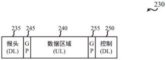
Fig. 2B illustrates an example of a subframe 230 associated with a UL-centric dynamic subframe type in accordance with one or more aspects of the present disclosure. In some examples, the UL-centric dynamic subframe type may be selected by the network access device for subframe 230 based at least in part on the UL/DL traffic ratio. For example, the network access device may select a UL-centric dynamic subframe type for subframe 230 if the UL/DL traffic ratio indicates that more traffic is queued by the one or more UEs for transmission to the network access device than is queued by the network access device for transmission to the one or more UEs. Alternatively, and as another example, the network access device may select a UL-centric dynamic subframe type for subframe 230 when the UL/DL ratio indicates that a particular percentage of the total amount of traffic queued for the one or more UEs is UL traffic or when a particular percentage of UL traffic included in the UL/DL ratio may be associated with a priority above a threshold. In some examples, the network access devices and UEs communicating in subframe 230 may be examples of aspects of the network access devices 105 and UEs 115 described with reference to fig. 1.
The subframe 230 may begin with a header 235 that includes a DL control region. The indication of the UL-centric dynamic subframe type of the subframe 230 may be transmitted by the network access device in the header 235 (and/or in the DL control region) to one or more UEs that transmit or receive data in the subframe 230. Following the header 235, the network access device can schedule a data region 240 (e.g., UL data region) of the subframe 230. The data region 240 may optionally be separated from the header 235 in the time domain for a first guard period 245 to give the UE time to perform an RF handover.
After the data region 240, the network access device may optionally schedule the DL control region 250 and/or allocate at least one HARQ transmission resource for the network access device to transmit HARQ feedback (e.g., one or more ACKs or NACKs) for the subframe 230 to one or more UEs. The DL control region 250 and/or the at least one HARQ transmission resource may optionally be bounded by a second guard period 225 in the time domain to give the UE time to perform an RF handover. Alternatively, the DL control region 250 may not be provided and may be incorporated into a DL control region of a later-transmitted subframe. In some examples, subframe 230 may have a self-contained subframe structure (e.g., a subframe structure in which all transmissions during a subframe are ACK or NAK during a subframe).
Fig. 2C illustrates an example of a subframe 265 associated with a bidirectional dynamic subframe type in accordance with one or more aspects of the present disclosure. In some examples, the bidirectional dynamic subframe type may be selected by the network access device for subframe 265 based at least in part on the UL/DL traffic ratio. For example, the network access device may select a bidirectional dynamic subframe type for subframe 265 if the UL/DL traffic ratio indicates that traffic is queued by the one or more UEs for transmission to the network access device and that traffic is queued by the network access device for transmission to the one or more UEs. Alternatively and as yet another example, the network access device may select a bidirectional dynamic subframe type for subframe 265 when a particular percentage of both UL traffic and DL traffic included in the UL/DL ratio is associated with a priority above a threshold. In some examples, the network access devices and UEs communicating in subframe 265 may be examples of aspects of the network access devices 105 and UEs 115 described with reference to fig. 1.
The sub-frame 265 may begin with a header 270 that includes a DL control region. The indication of the bidirectional dynamic subframe type of subframe 265 may be transmitted by the network access device in header 270 (and/or in the DL control region) to one or more UEs transmitting or receiving data in subframe 265. Following the header 270, the network access device may schedule a UL control region 275 followed by multiple data regions of the subframe 265, e.g., a first data region 280 (e.g., a DL data region) and a second data region 285 (e.g., a UL data region). The UL control region 275 may optionally be separated from the header 270 in the time domain for a first guard period 290 to give the UE 115 time to perform an RF handover. Similarly, the second data region 285 may optionally be separate from the first data region 280 for a second guard period 295. In some examples, the second data region 285 may be a portion of an UL region that includes another UL control region and/or an allocation of at least one HARQ transmission resource for the UE 115 (or UEs 115) to transmit HARQ feedback (e.g., one or more ACKs or NAKs) for the subframe 265 to the network access device; alternatively, the UL control information may also be relinquished to a later transmitted UL control region, thereby rendering the subframe structure non-self-contained.
After the second data region 285, the network access device may optionally schedule a downlink control region 297 and/or allocate at least one HARQ transmission resource for the network access device to transmit HARQ feedback (e.g., one or more ACKs or NAKs) for subframe 265 to one or more UEs. Alternatively, the DL control region 297 may not be included in the subframe 265 and may be incorporated into a DL control region of a later-transmitted subframe. In some examples, subframe 265 may have a self-contained subframe structure (e.g., a subframe structure in which all transmissions during a subframe are ACK or NAK during a subframe).
Some subframes (some subframes other than those shown in fig. 2A, 2B, and 2C) may be associated with other dynamic subframe types, such as full-duplex dynamic subframe types (not shown). The headers 205, 235, and 270 of the subframes 200, 230, and 265 described with reference to fig. 2A, 2B, and 2C may have the same or similar structure, with each header including an indication of a dynamic subframe type. In some examples, the dynamic subframe type may be identified before a data region of the corresponding subframe is decoded or transmitted. In some examples, the dynamic subframe type associated with a subframe may be transmitted to the UE in the first symbol period in time in the two (or more) symbol period DL control region. In this manner, the UE may complete identification (e.g., decoding) of the dynamic subframe type during a second or subsequent symbol period of the DL control region (i.e., prior to receiving the data region of the subframe). In the case of a subframe with a UL data region after the subframe header, the UE may complete identification (e.g., decoding) of the dynamic subframe type associated with the subframe during a guard period after the header.
In some examples, the dynamic subframe type may be indicated by broadcasting the dynamic subframe type to a UE associated with a network access device (or cell). In some examples, the dynamic subframe type may be indicated by unicasting the dynamic subframe type to a subset of UEs associated with the network access device (or cell). In some examples, the subset of UEs to which the dynamic subframe type is unicast may include a subset of UEs active during subframes of the dynamic subframe type of which it is unicast (e.g., a subset of non-continuous reception (non-CDX) mode UEs). Unicast transmission of dynamic subframe types may be useful, for example, if the wireless communication system or network access device allows multiplexing (or simultaneous transmission) of different dynamic subframe types or when multiple UEs support only unicast control. In some examples, the dynamic subframe type may be indicated by transmitting an indication of the dynamic subframe type within a narrow frequency band of the system bandwidth, as described with reference to fig. 3.
In some examples, the dynamic subframe type may be indicated by transmitting an indicator (or set of indicators) that distinguishes between a DL centric dynamic subframe type and a UL centric dynamic subframe type, or an indicator (or set of indicators) that distinguishes between a DL centric dynamic subframe type, a UL centric dynamic subframe type, a full duplex dynamic subframe type, a dynamic switching dynamic subframe type, a hybrid interference measurement dynamic subframe type, or a distributed scheduling dynamic subframe type. In some cases, the dynamic subframe type may be determined using a combination of the indicated content (i.e., one or more bits) and any context or mode that has been configured. That is, the number of bits used for indication may be content dependent. For example, a wireless communication system may be configured to support a subset of dynamic subframe types, and the subset of dynamic subframe types may not change dynamically. As a result, the indication may only need to specify which dynamic subframe type(s) of the subset of dynamic subframe types are used for TDD subframes. In another example, the UE may have previously used a subset of dynamic subframe types, and based on the previously used subset of dynamic subframe types, the UE may determine how to interpret the bits for the dynamic subframe type indication. Accordingly, the additional information associated with identifying the respective dynamic subframe type may be kept relatively small.
In some examples, the dynamic subframe type may be indicated by transmitting at least one of: a first bit indicating a UL data transmission direction or a DL data transmission direction, and/or a second bit indicating a half-duplex data transmission or a full-duplex data transmission. In some examples, a UE that is not capable of communicating according to the full-duplex subframe structure may ignore the second bit and communicate according to the first bit or ignore the subframe when the second bit indicates a full-duplex dynamic subframe type.
Fig. 3 illustrates an example 300 of a first subframe 305 associated with a DL-centric dynamic subframe type and a second subframe 310 associated with an UL-centric dynamic subframe type in accordance with one or more aspects of the present disclosure. In some examples, the network access devices and UEs communicating in the first subframe 305 or the second subframe 310 may be examples of aspects of the network access devices 105 and UEs 115 described with reference to fig. 1.
As described above, some subframes may have a self-contained subframe structure. In the example of fig. 3, subframe 305 includes a DL portion 315 and an UL portion 320. The UL portion 320 may be bounded on either side by guard periods in the time domain. DL control region 325 may be transmitted at the beginning of DL portion 315 within a subset of the frequency resources of DL portion 315 and over one or more two symbol periods of DL portion 315. The DL control region 325 may include an indication of a dynamic subframe type (e.g., a DL centric dynamic subframe type) of the subframe 305. In some examples, the DL control region 325 may include a subset of frequency resources having a narrower bandwidth than the total bandwidth used for communication between the network access device and the UE.
The relatively narrower bandwidth of the DL control region 325 may allow for reduced reference signal (e.g., cell-specific reference signal (CRS)) overhead relative to a wider bandwidth and may allow lower layer UEs (e.g., Machine Type Communication (MTC) UEs) to access the network through the network access device with reduced hardware complexity and reduced power consumption. In some examples, the resources of DL control region 325 may be multiplexed in frequency within the symbols used to transmit DL control region 325, with resources allocated to DL data region 330. The frequency multiplexing of the DL control region 325 may enable utilization of more or all of the channel bandwidth during the symbols used to transmit the DL control region 325, although the DL control region 325 occupies only a narrow portion of the total bandwidth used for communication between the network access device and the UE. In some examples, the subframe 305 may end with a UL transmission 335, which when its structure is shared by subframes associated with a TDD DL-centric subframe type and subframes associated with a TDD UL-centric subframe type may be referred to as a "UL common burst. In some examples, the scheduling of UL transmissions 335 may be independent of DL data region 330, or may be scheduled in advance.
In sub-frame 310, DL portion 340 is located at the beginning of sub-frame 310, followed by guard period 355 during which the RF circuitry may switch from a receive mode to a transmit mode, followed by UL portion 360. The second guard period 370 may follow the UL portion 360 to provide a DL control region where transmit/receive circuitry switches from transmit mode back to receive mode in preparation for receiving subsequent subframes. Within the DL portion 340, a DL control region 350 may occupy a portion of the entire transmission bandwidth, similar to the DL control region 325 of the subframe 305.
The DL control region 350 may include an indication of a dynamic subframe type (e.g., UL-centric dynamic subframe type) of the subframe 310. The DL control region 350 may be multiplexed with other DL data resources 345 in order to utilize the entire transmission bandwidth. UL portion 360 may include UL data region 365. The UL portion 360 may also include UL common bursts 335, which may be formatted similarly to the UL common bursts described with reference to the subframe 305. Thus, DL centric sub-frame 305 and UL centric sub-frame 310 may have a self-contained TDD sub-frame structure.
The dynamic subframe type may be indicated in various ways. For example, the indication of the dynamic subframe type may be embedded in a reference signal (such as CRS). In some examples, when embedded in a reference signal, a hypothesis test may be used to determine a value of one bit of information indicative of a DL centric dynamic subframe type or an UL centric dynamic subframe type. As another example, the indication of the dynamic subframe type may be transmitted in a subframe type indicator channel, such as described with reference to fig. 7. As yet another example, the dynamic subframe type may be indicated by transmitting a DCI type corresponding to the dynamic subframe type. For example, a DL assignment may be transmitted in a subframe associated with a DL-centric dynamic subframe type, while an UL grant may be transmitted in a subframe associated with a UL-centric dynamic subframe type. In some examples, other types of DCI may be transmitted for subframes with a bidirectional dynamic subframe type or a full-duplex dynamic subframe type.
Fig. 4A, 4B, and 4C illustrate examples of dynamic subframe types for dynamic frame switching. In some cases, a wireless communication system may support dynamic scheduling of hybrid UL and DL transmissions, and may use UL or DL centric dynamic subframes that include additional features used in dynamic frame switching environments, such as channel clearing features (e.g., Clear To Send (CTS) messages) and override messages. The dynamic subframe types illustrated in fig. 4A, 4B, and 4C may be examples of dynamic subframe types selected for TDD subframes. Fig. 4A illustrates an example of a subframe 400 associated with dynamically switching dynamic subframe types in accordance with one or more aspects of the present disclosure. In some cases, dynamically switching dynamic subframe types may be selected for subframe 400 by a network access device (such as a base station) based at least in part on traffic conditions (such as UL/DL traffic ratio). In some examples, the network access devices and UEs communicating in subframe 400 may be examples of aspects of the network access devices 105 and UEs 115 described with reference to fig. 1.
The subframe 400 may begin in a DL/UL scheduling information region 405, where an indication of a dynamically switched dynamic subframe type of the subframe 400 may be transmitted by a network access device in the DL/UL scheduling information region 405, in a control region, or in some other region to one or more UEs that may transmit or receive data in the subframe 400. In some cases, the DL/UL scheduling information may be transmitted in a control channel (e.g., a Physical Downlink Control Channel (PDCCH)) and may be transmitted to the UE in a first symbol period over the time of two (or more) symbol periods control region.
After the DL/UL scheduling information region 405, the network access device may schedule a DL/UL CTS region 415. The DL/UL CTS region may include CTS messages from neighboring devices (e.g., neighboring UEs and network access devices) communicating to clear a channel, such as a channel in an unlicensed RF spectrum. As a result, the CTS message may silence the surrounding devices and any interference that may be caused by these devices. The DL/UL CTS region 415 may be bounded by a first guard period 410 and a second guard period 420. The DL/UL data region 425 of the subframe 400 may then be scheduled by the network access device, and the UL control region 430 may follow the DL/UL data region 425 of the subframe 400. In some examples, the subframe 400 may have a self-contained dynamic switching dynamic subframe structure (e.g., a subframe structure in which all transmissions during a subframe are ACK or NACK during a subframe).
Fig. 4B illustrates an example of subframes 435 associated with dynamically switching dynamic subframe types in accordance with one or more aspects of the present disclosure. Dynamically switching the dynamic subframe type may be selected by the network access device for subframe 435 based at least in part on traffic conditions. In some examples, the network access devices and UEs communicating in subframe 435 may be examples of aspects of the network access devices 105 and UEs 115 described with reference to fig. 1. The subframe 435 may start from the DL/UL scheduling information region 440. As described above, the indication of the dynamically switched dynamic subframe type of the subframe 435 may be transmitted using the DL/UL scheduling information region 440, the control region, or in some other region. In some examples, the indication of the dynamically switched dynamic subframe type may be included in the first symbol period in time of the two (or more) symbol period control regions of subframe 435. In this manner, the UE may complete the identification (e.g., decoding) of the dynamic switching dynamic subframe type during a second or subsequent symbol period of the DL control region (i.e., prior to receiving the data region of the subframe).
After the DL/UL scheduling information region 440, the network access device may schedule a DL/UL data region, where the DL/UL data region 450 may be separated from the DL/UL scheduling information region 440 by a guard period 445. A UL control region 455 for UE UL control information transmission may be included in the subframe 435 after the DL/UL data region 450.
Fig. 4C illustrates an example of a subframe 460 associated with dynamically switching dynamic subframe types in accordance with one or more aspects of the present disclosure. Dynamically switching the dynamic subframe type may be selected by the network access device for the subframe 460 based at least in part on traffic conditions. In some examples, the network access devices and UEs communicating in subframe 460 may be examples of aspects of the network access devices 105 and UEs 115 described with reference to fig. 1. The subframe 460 may begin in a DL/UL scheduling information region 465, which may include an indication of the dynamic subframe type in the first symbol period in time.
The subframe 460 may include a DL/UL override region 475 after the DL/UL scheduling information region 465. DL/UL override region 475 may include an override message that provides an indication of resources associated with DL or UL communications. In some examples, the DL/UL override region 475 may optionally be bounded by a first guard period 470 and a second guard period 480. The network access device may further schedule a DL/UL data region 485 in the subframe 460 before the UL control region 490.
The dynamic switching dynamic subframe type may be indicated in various ways. For example, an indication of a dynamically switched dynamic subframe type may be embedded in the reference signal. As another example, the indication of the dynamic switching dynamic subframe type may be transmitted in a subframe type indicator channel, such as described with reference to fig. 7. In another example, the dynamic switching dynamic subframe type may be indicated by transmitting a DCI type corresponding to the dynamic switching dynamic subframe type.
Fig. 5A and 5B illustrate various examples of dynamic subframe types that may be used to update a jamming graph based on mixed interference measurements. In some cases, a wireless communication system may support hybrid UL and DL transmissions, which may be scheduled by a network access device for a network based at least in part on a jamming graph (e.g., a semi-statically updated jamming graph summarizing UL/DL and DL/UL hybrid interference). Accordingly, the network access device may schedule a hybrid interference measurement dynamic subframe type. The dynamic subframe types illustrated in fig. 5A and 5B may be examples of dynamic subframe types selected for TDD subframes. Fig. 5A illustrates an example of a subframe 500 associated with a mixed interference measurement dynamic subframe type in accordance with one or more aspects of the present disclosure. In some cases, a mixed interference dynamic subframe type may be selected for subframe 500 by a network access device (such as a base station) based at least in part on traffic conditions (e.g., UL/DL traffic ratio). Subframe 500 may illustrate examples of UL-centric dynamic subframe types scheduled for respective UEs (e.g., subframes 505-a, 505-b, and 505-c for first, second, and third UEs, respectively). In some examples, network access devices and UEs communicating using the subframe 500 may be examples of aspects of the network access devices 105 and UEs 115 described with reference to fig. 1.
Each of the subframes 500 may begin with a DL control region 510, which may include an indication of a mixed interference measurement dynamic subframe type of the subframe 500 to a plurality of UEs that may transmit or receive data in subframes 505-a, 505-b, and 505-c. In some examples, the hybrid interference measurement dynamic subframe type may be identified before other regions of the corresponding subframe are decoded or transmitted. For example, a mixed interference measurement dynamic subframe type associated with subframe 500 may be transmitted to a UE in the first symbol period in time in a two (or more) symbol period DL control region. In this manner, the UE may complete identification (e.g., decoding) of the hybrid interference measurement dynamic subframe type during a second or subsequent symbol period of the DL control region (i.e., prior to receiving the data region of the subframe).
After the DL control region 510, the network access device may schedule a measurement region 520 in each of the subframes 500, where the measurement region 520 is separated from the DL control region 510 by a guard period 515 in some examples. Measurement region 520 may be used by a UE to transmit during a subset of SRS regions and perform channel measurements (e.g., from other UEs using subframe 500) during SRS regions where the UE is not transmitting. For example, a first UE may transmit SRS in a first subset of SRS regions of the first subframe 505-a (e.g., SRS regions 525 transmitted in SRS regions 1 and 2) and may listen for the remaining duration of the measurement region 520 (e.g., SRS regions 3 through 6). Using second subframe 505-b, the second UE may perform measurements of SRS transmitted by the first UE (during SRS region 525) and transmit SRS in a second subset of SRS regions (e.g., SRS regions 530 transmitted in SRS regions 3 and 4) and perform measurements later in the remaining measurement region 520. Additional UEs scheduled to use the hybrid interference measurement dynamic subframe type may perform similar operations during different SRS region subsets (e.g., a third UE may perform measurements in subframe 505-c while the first and second UEs transmit SRS, and later transmit SRS during SRS region 535). The network access device may then schedule the UL control region 540 in each of the subframes 500. In some examples, the subframe 500 may have a self-contained hybrid interference measurement dynamic subframe structure (e.g., a subframe structure in which all transmissions during a subframe are ACK or NACK during a subframe).
Fig. 5B illustrates an example of a subframe 550 associated with a mixed interference measurement dynamic subframe type in accordance with one or more aspects of the present disclosure. In some cases, a mixed interference dynamic subframe type may be selected for subframe 550 by a network access device (such as a base station) based at least in part on a UL/DL traffic ratio. The subframes 550 may illustrate examples of UL-centric dynamic subframe types scheduled for respective UEs (e.g., subframes 555-a, 555-b, and 555-c for first, second, and third UEs, respectively), where the UEs may be scheduled to transmit simultaneously (e.g., using different frequency resources). In some examples, the network access devices and UEs communicating using the subframe 550 may be examples of aspects of the network access devices 105 and UEs 115 described with reference to fig. 1.
Each of the subframes 550 may begin with a DL control region 560, which may include an indication of a mixed interference measurement dynamic subframe type for the subframe 550 to a plurality of UEs that may transmit or receive data in subframes 555-a, 555-b, and 555-c. For example, a mixed interference measurement dynamic subframe type associated with subframe 550 may be transmitted to the UE in the first symbol period in time in the two (or more) symbol period DL control region. After DL control region 560, the network access device may schedule measurement region 570 in each of subframes 550. Measurement region 570 may be used by a UE to transmit during a subset of SRS regions (which may correspond to a sub-band division of a subframe) and to perform signal measurements (e.g., from other UEs using subframe 550) during SRS regions where the UE is not transmitting.
In some cases, different UEs may be grouped to transmit (using different frequency resources) and collectively perform measurements based at least in part on a mixed interference measurement dynamic subframe type. For example, a first UE may transmit SRS in a subset of SRS regions in subframe 555-a using a first set of frequency resources (e.g., SRS regions 575 transmitted in SRS regions 1 and 2). A second UE may transmit simultaneously in a subset of SRS regions in subframe 555-b using a different set of frequency resources (e.g., SRS region 580 in SRS regions 1 and 2). The first and second UEs may perform measurements at other times of measurement region 570, or may transmit additional SRS using different sets of frequency resources (e.g., in coordination with other UEs). The network access device may then schedule a UL control region 595 in each of the subframes 500 after the guard period 590. In some examples, the subframe 550 may have a self-contained hybrid interference measurement dynamic subframe structure (e.g., a subframe structure in which all transmissions during a subframe are ACK or NACK during a subframe).
The hybrid interference measurement dynamic subframe type may be indicated in various ways. For example, an indication of a mixed interference measurement dynamic subframe type may be embedded in the reference signal. As another example, the indication of the hybrid interference measurement dynamic subframe type may be transmitted in a subframe type indicator channel, such as described with reference to fig. 7. As yet another example, the hybrid interference measurement dynamic subframe type may be indicated by transmitting a DCI type corresponding to a distributed scheduling dynamic subframe type.
Fig. 6 illustrates an example of a subframe 600 associated with a distributed scheduling dynamic subframe type in accordance with one or more aspects of the present disclosure. In some examples, a wireless communication system may include a distributed scheduling technique for a subset of UEs (i.e., scheduling may not be focused on a network access device, even if the network access device is part of a network). As a result, scheduling of dynamic subframes for unsolicited access based (e.g., Request To Send (RTS) -CTS signaling, node discovery, etc.) may be dynamically signaled by a network access device. In some cases, a distributed scheduling dynamic subframe type may be selected for subframe 600 by a network access device (such as a base station) based at least in part on traffic conditions (such as a UL/DL traffic ratio). Subframe 600 may illustrate an example of a dynamic subframe type scheduled for a UE, which may be an example of an MTC-type UE. In some examples, network access devices and UEs communicating using subframe 600 may be examples of aspects of network access devices 105 and UEs 115 described with reference to fig. 1.
Following PDCCH 610, the network access device may schedule one or more partitioned regions (such as RTS/CTS/data/ACK region 620) within subframe 600 for use by one or more UEs. In some examples, the RTS/CTS/data/ACK region 620 may enable the use of RTS and CTS channel clearing techniques to enable the transmission of data or ACK/NACK within the same RTS/CTS/data/ACK region 620. In some cases, the RTS/CTS/data/ACK region may include gaps during which no transmissions are made. The RTS/CTS/data/ACK region 620 may be followed by a common UL burst 630. The UL burst 630 may be used, for example, to transmit an indication of subsequent traffic and/or to request additional resources. In some examples, subframe 600 may have a self-contained distributed scheduling dynamic subframe structure (e.g., a subframe structure in which all transmissions during a subframe are ACK or NACK during a subframe).
The distributed scheduling dynamic subframe type may be indicated in various ways. For example, an indication of a distributed scheduling dynamic subframe type may be embedded in a reference signal. As another example, the indication of the distributed scheduling dynamic subframe type may be transmitted in a subframe type indicator channel, such as described with reference to fig. 7. As yet another example, the distributed scheduling dynamic subframe type may be indicated by transmitting a DCI type corresponding to the distributed scheduling dynamic subframe type.
Fig. 7 is a flow diagram illustrating an example of a method 700 for indicating a dynamic subframe type in a subframe type indicator channel in accordance with one or more aspects of the present disclosure. In some examples, method 700 may be performed by a network access device, such as one of network access devices 105 described with reference to fig. 1.
The method 700 begins by receiving a dynamic subframe type indicator 705. In some examples, the dynamic subframe type indicator 705 may include one or two bits of information (e.g., a first bit indicating a UL data transmission direction or a DL data transmission direction and/or a second bit indicating a half-duplex data transmission or a full-duplex data transmission). In other examples, the dynamic subframe type indicator 705 may carry more bits to specify a subset of subframe attributes (e.g., subframe parameters) as described above. The method 700 may encode and scramble the dynamic subframe type indicator 705 at blocks 710 and 715. For example, the dynamic subframe type indicator 705 may be block coded at block 710 and binary scrambled at block 715. In some examples, the binary scrambling may be cell-specific and, in some examples, may be based on a gold sequence initialized with a subframe number and a cell Identifier (ID). In some examples, the encoding and processing of blocks 710 and 715 may be similar to the encoding and processing of a Physical Channel Format Indicator Channel (PCFICH) in an LTE/LTE-a network.
At block 720, the dynamic subframe type indicator 705 may be modulated (e.g., Quadrature Phase Shift Keying (QPSK) modulation). At block 725, the dynamic subframe type indicators 705 may be mapped to the tones. At block 730, the dynamic subframe type indicator 705 may be Orthogonal Frequency Division Multiplexing (OFDM) modulated on a subframe type indicator channel. As previously described, in some examples, the dynamic subframe type indicator 705 may be transmitted over a narrowband and/or one symbol period (e.g., one OFDM symbol period).
Fig. 8A illustrates an example timeline 800 of operations performed by a network access device for subframes 805 associated with a DL centric dynamic subframe type in accordance with one or more aspects of the present disclosure. In some examples, the network access device may be an example of one of the network access devices 105 (e.g., an eNB, ANC, RH, or base station) described with reference to fig. 1.
At time T-eNB-frame ticks, the modem of the network access device may send a frame tick indication to the MAC layer, which may trigger processing at the MAC layer. Because the dynamic subframe type of the next subframe (e.g., subframe 805) is a DL centric dynamic subframe type, the MAC layer may begin the computation of DL assignments (and some UL grants) for a set of one or more UEs connected to the network access device.
At time T-eNB-grant, the MAC layer may send DL grants (as well as UL grants) to the modems of all scheduled UEs. In some examples, the MAC layer may send a retransmission (ReTx) indicator (e.g., an indicator of whether data to be transmitted to the UE is new data, ReTx or auto ReTx (autoretx)), and a DL grant. At time T-eNB-DL data, the MAC layer may begin a Direct Memory Access (DMA) transfer of DL data to the modem (e.g., a transfer of all Transport Blocks (TBs) for all scheduled UEs). At time T-eNB-DLAck, the modem may send a DL ACK or NACK. In some cases, the UL control region may optionally include UL data, and at time T-eNB-UL data, the modem may send UL data (e.g., TBs for all scheduled UEs) received during the UL control region of subframe 805 (e.g., during symbol 14) to the MAC layer.
Fig. 8B illustrates an example timeline 850 of operations performed by a network access device for subframes 855 associated with a UL-centric dynamic subframe type in accordance with one or more aspects of the present disclosure. In some examples, the network access device may be an example of one of the network access devices 105 (e.g., an eNB, ANC, RH, or base station) described with reference to fig. 1.
At time T-eNB-frame ticks, the modem of the network access device may send a frame tick indication to the MAC layer. This may trigger processing at the MAC layer. Because the dynamic subframe type of the next subframe (e.g., subframe 855) is a UL centric dynamic subframe type, the MAC layer may begin the calculation of UL grants for a set of one or more UEs connected to the network access device. At time T-eNB-grant, the MAC layer may send UL grant to the modems of all scheduled UEs. In some examples, the MAC layer may send a ReTx indicator along with an UL grant. In some examples, the DL control region may optionally include DL data for one or more scheduled UEs. At time T-eNB-UL data, the modem may send UL data (TBs for all scheduled UEs) received during subframe 855 to the MAC layer.
Given the similarity between MAC layer processing across subframes associated with DL centric dynamic subframe types and subframes associated with UL centric dynamic subframe types, a MAC layer processor at a network access device (e.g., an eNB) may handle UL and DL subframe operations. Further, the MAC layer processor at the network access device may be configured to handle simultaneous UL and DL transmissions for full-duplex dynamic subframe types (not shown).
Fig. 9A illustrates an example timeline 900 of operations performed by a UE for subframes 905 associated with a DL-centric dynamic subframe type in accordance with one or more aspects of the present disclosure. In some examples, the UE may be an example of one of the UEs 115 described with reference to fig. 1.
At time T-UE-frame tick, the UE's modem may send a frame tick indication to the MAC layer, which may trigger processing at the MAC layer. The MAC layer may initially assume that the dynamic subframe type of the next subframe (e.g., subframe 905) is a UL-centric dynamic subframe type. If it is later determined that the dynamic subframe type of subframe 905 is a DL centric dynamic subframe type, the MAC layer may not perform further actions on subframe 905. Processing at the MAC layer may include estimation of the smallest expected UL grant (e.g., grant prediction). At time T-UE-UL data 1, the MAC layer may send UL data (e.g., UL data 1) to the modem. UL data 1 may include an estimated minimum TB size (e.g., grant prediction) for subframe 905.
At time T-UE-grant, the modem may send DL assignment or UL grant information received in one or more symbols of the DL control region of subframe 905 to the MAC layer. Upon the MAC layer identifying a DL assignment for the DL centric subframe type, the MAC layer may then assume that the TB sent in the UL data 1 command has been discarded by the modem. If the MAC layer identifies a UL grant for a DL centric dynamic subframe type, the MAC layer may start creating a TB. At time T-UE-UL data, the MAC layer may send UL data including TBs for transmission during the UL control portion of subframe 805. At time T-UE-DL data, the modem may send a DL data indication indicating that the TB has been received.
Fig. 9B illustrates an example timeline 950 of operations performed by a UE for subframes 955 associated with a UL-centric dynamic subframe type in accordance with one or more aspects of the present disclosure. In some examples, the UE may be an example of one of the UEs 115 described with reference to fig. 1.
When the UE receives a dynamic subframe type indicator during the first symbol period of the two symbol period DL control region, the two symbol period DL control region may allow time for processing (e.g., PHY layer and/or modem processing) of the received subframe type indicator. At time T-UE-frame tick, the UE's modem may send a frame tick indication to the MAC layer. This may trigger processing at the MAC layer. The MAC layer may initially assume that the dynamic subframe type of the next subframe (e.g., subframe 955) is a UL centric dynamic subframe type. If it is later determined that the dynamic subframe type of subframe 955 is a DL centric dynamic subframe type, the MAC layer may perform no further action on subframe 955. Processing at the MAC layer may include estimation of the smallest expected UL grant (e.g., grant prediction).
At time T-UE-UL data 1, the MAC layer may send UL data (e.g., UL data 1) to the modem. UL data 1 may include an estimated minimum TB size (e.g., grant prediction) for subframe 955. At time T-UE-grant, the modem may send DL assignment or UL grant information received in one or more symbols of the DL control region of subframe 905 to the MAC layer. Upon the MAC layer identifying the UL grant for the UL-centric dynamic subframe type, the MAC layer may then construct the rest of the TB for the subframe. At time T-UE-UL data 2, the MAC layer may send additional UL data (e.g., UL data 2) to the modem to complete the TB for subframe 955.
As discussed above, the two-symbol control region may provide the UE with time for PHY layer/modem processing. For example, the UE may perform (or complete) reference signal processing and channel estimation, as well as dynamic subframe type indicator demodulation and decoding during the second symbol period of the DL control region. For DL centric sub-frames, DCI (e.g., DL assignment) of DL data may be processed and decoded during reception of the DL control region. For DL centric subframes having a structure in which demodulation reference signals (DMRSs) are transmitted in the first and/or second symbol periods (e.g., where DMRSs are FDM within the DL control region), and in some examples, a UE may begin processing DMRSs from buffered samples as soon as the DL assignment is decoded. In a DL centric subframe, there may be no need to switch RF direction. For a UL-centric sub-frame, during reception of the DL control region, DCI (e.g., UL grant) for UL data may be processed and decoded. In some examples, the UE may begin to prepare for UL data transmission for at least a first symbol period as soon as the UL grant is decoded. When something else, such as a DMRS pilot signal or a common UL burst (e.g., a UL burst carrying an unscheduled UL transmission, such as a Sounding Reference Signal (SRS)), may be transmitted before the first symbol period of the UL data transmission, the preparation of the UL data may be slowed down.
Fig. 10 illustrates an example of resources and UE processing timing for a subframe 1000 associated with a DL centric dynamic subframe type in accordance with one or more aspects of the present disclosure. In some examples, fig. 10 may represent aspects of the processing performed by the modem of UE 115 described with reference to fig. 1.
In the example of fig. 10, a DL portion 1005 of a subframe 1000 may be received at a UE, followed by a guard period and UL portion 1010 of the subframe. In this example, the DL portion 1005 received at the UE may include a first symbol period in time, which may include reference signal (e.g., CRS) pilot Resource Elements (REs) 1025, control symbol REs 1030 (including dynamic subframe type indicators) embedded with the reference signal pilot REs 1025, and DRMS REs 1040 and 1045. The control symbol RE 1030 may include Physical DL Control Channel (PDCCH) information including resource allocation and processing parameters, such as Modulation and Coding Scheme (MCS), New Data Indicator (NDI), and Redundancy Version (RV), for the data symbol 1050. The second symbol period in time, received at the UE in this example, may include other control symbols RE 1035 and DMRS REs 1040 and 1045. In some examples, other control symbols RE 1035 may be included in the control bandwidth but may not contain PDCCH information. Following data symbols 1050, subframe 1000 may include a guard period in UL portion 1010 along with UL pilot 1055 and UL ACK/NACK symbol period 1060. The sub-frame 1000 may end at the final guard period.
During time period 1065, the UE may process the reference signals and the dynamic subframe type indicator received in the first symbol period of subframe 1000. At this time, the dynamic subframe type may be unknown. After the dynamic subframe type is known, the UE may decode the PDCCH and search for DL assignments. This may occur during time period 1070. Upon decoding the DL assignment, the Resource Block (RB) allocation of the DL assignment may be known and DMRS processing may begin (e.g., during time period 1075). Alternatively, DMRS processing may start before knowing the RB allocation. However, this may cause processing of unallocated RBs to waste processing resources. After DMRS processing, the data region of DL portion 1005 may be processed (e.g., during time period 1080). Because data may be transmitted during the third and fourth symbol periods over time of subframe 1000, some catching up with respect to data symbol processing may be performed (e.g., processing twelve symbols in approximately eleven symbol times). However, when the PDCCH and DMRS can fit into the second symbol period, any catch-up of data symbol processing may no longer be required. In fig. 10, the Cyclic Prefix (CP) may be a portion of each symbol, and thus is not explicitly shown.
Fig. 11 illustrates an example of resources and UE processing timing for a subframe 1100 associated with a UL-centric dynamic subframe type in accordance with one or more aspects of the present disclosure. In some examples, fig. 11 may represent aspects of the processing performed by the modem of UE 115 described with reference to fig. 1.
In the example of fig. 11, a DL portion 1110 of a subframe 1100 may be received at a UE, followed by a guard period 1115 and an UL portion 1120 of the subframe 1100. In this example, DL portion 1110 received at the UE may include a first symbol period in time, which may include reference signal pilot REs 1125, control symbol REs 1130 (including dynamic subframe type indicators) embedded within reference signal pilot REs 1125. Control symbol RE 1130 may also include a UL grant for the UE. In this example, the second symbol period in time received at the UE may include additional control symbols RE 1135. The additional control symbol REs 1135 may include PDCCH information, which includes resource allocation and processing parameters, such as the MCS for the data symbols 1150. In some examples, additional control symbol REs 1135 may be included in the control bandwidth but may not contain PDCCH information. After the guard period 1115, DMRS REs 1140 and 1145 may be transmitted in the first two UL symbol periods of the UL data region, followed by UL data symbols 1150.
During time period 1165, the UE may process the reference signals and dynamic subframe type indicators received in the first symbol period of subframe 1100. At this time, the dynamic subframe type may be unknown. After the dynamic subframe type is known, the UE may decode the PDCCH and search for UL grants. This may occur during time period 1170. An RF switch from receive mode to transmit mode may also occur during time period 1170. Upon decoding the UL grant, the RB allocation of the UL grant is known and DMRS processing/transmission may begin (e.g., during time period 1175). Alternatively, partial preprocessing of DMRS may start before knowing the RB allocation. However, this may cause processing of unallocated RBs to waste processing resources. UL data symbol processing (e.g., encoding and modulation for the previous data symbol or symbols) may also begin during time period 1175. After DMRS processing, the data region of UL portion 1120 may be processed and transmitted (e.g., during time period 1180). In fig. 11, the CP may be a part of each symbol, and thus is not explicitly shown.
Fig. 12 illustrates an example of resources and UE processing timing for a subframe 1200 associated with a UL-centric dynamic subframe type in accordance with one or more aspects of the present disclosure. In some examples, fig. 12 may represent aspects of the processing performed by the modem of UE 115 described with reference to fig. 1.
In the example of fig. 12, a DL portion 1210 of a subframe 1200 may be received at a UE, followed by a guard period 1215, a non-time critical UL burst 1255, and an UL portion 1220 of the subframe 1200. In this example, the DL portion 1210 received at the UE may include a first symbol period in time, which may include reference signal pilot REs 1225, control symbol REs 1230 (including dynamic subframe type indicators) embedded within the reference signal pilot REs 1225. Control symbol RE 1230 may also include a UL grant for the UE. In this example, the second symbol period in time received at the UE may include additional control symbols 1235.
After guard period 1215, a non-time critical UL burst 1255 may be transmitted in the first symbol period of the UL data region. The non-time critical UL burst 1255 may be prepared in advance and may provide the UE with additional processing time to prepare the DMRS and/or UL data symbols 1250 for transmission in the UL data region (or UL portion 1220). In some examples, the non-time critical UL burst 1255 may include unscheduled (or a priori scheduled) UL transmissions, such as SRS or Channel Quality Indicator (CQI). DMRS REs 1240 and 1245 may be transmitted in the second and third UL symbol periods of the UL data region, followed by UL data symbol 1250. The additional control symbol RE 1235 may include PDCCH information including resource allocation and processing parameters, such as the MCS for the data symbol 1250. In some examples, additional control symbols RE 1235 may be included in the control bandwidth but may not contain PDCCH information.
During time period 1265, the UE may process the reference signal and the dynamic subframe type indicator received in the first symbol period of subframe 1200. At this time, the dynamic subframe type is unknown. After the dynamic subframe type is known, the UE may decode the PDCCH and search for UL grants. This may occur during time period 1270, which time period 1270 may be longer than time period 1170 described with reference to fig. 11 because of the transmission of non-time critical UL bursts 1255. An RF switch from receive mode to transmit mode may also occur during time period 1170. Upon decoding the UL grant, the RB allocation of the UL grant is known, and DMRS processing/transmission may begin (e.g., during time period 1275). Alternatively, partial preprocessing of DMRS may start before knowing the RB allocation. However, this may cause a waste of processing resources due to DMRS processing of unallocated RBs. UL data symbol processing (e.g., encoding and modulation for the previous data symbol or symbols) may also begin during time period 1275. After DMRS processing, the data region of UL portion 1220 may be processed and transmitted (e.g., during time period 1280). In fig. 12, the Cyclic Prefix (CP) may be a portion of each symbol, and thus is not explicitly shown.
Since HARQ feedback depends on the direction of data transmission in a subframe, the selection of a dynamic subframe type for a subframe may be used as a basis for allocating HARQ resources for the subframe. When the subframe is self-contained, HARQ resources may be allocated within the subframe. For subframes associated with a DL-centric dynamic subframe type, a HARQ transmission period (e.g., a UL transmission period) may be allocated to a subframe at the end of the subframe. For subframes associated with a UL-centric dynamic subframe type, a HARQ transmission period (e.g., a DL transmission period) may be allocated to a subframe at the end of the subframe, or at least one HARQ transmission resource of a subframe may be allocated in a DL control region of a subsequent subframe.
When the subframe includes at least one DL data region and at least one UL data region, at least one DL HARQ transmission resource may be allocated to the subframe in the subframe, and at least one UL HARQ transmission resource may be allocated to the subframe in the subframe (or at least one DL HARQ transmission resource may be allocated in a DL control region of a subsequent subframe).
Fig. 13 illustrates a block diagram 1305 of an apparatus 1300 for use in wireless communications, in accordance with one or more aspects of the present disclosure. The apparatus 1305 may be an example of aspects of one or more of the network access devices 105 described with reference to fig. 1. The apparatus 1305 may also be or include a processor. The apparatus 1305 may include a receiver 1310, a wireless communication manager 1320, or a transmitter 1330. Each of these components may be in communication with each other.
The components of the apparatus 1305 may be implemented individually or collectively using one or more Application Specific Integrated Circuits (ASICs) adapted to perform some or all of the applicable functions in hardware. Alternatively, the functions may be performed by one or more other processing units (or cores), on one or more Integrated Circuits (ICs). In some other examples, other types of integrated circuits (e.g., structured/platform AISCs, Field Programmable Gate Arrays (FPGAs), systems on a chip (socs), and/or other types of semi-custom ICs) may be used that may be programmed in any manner known in the art. The functions of each component may also be implemented, in whole or in part, with instructions stored in a memory that is formatted to be executed by one or more general or special purpose processors.
In some examples, receiver 1310 may include at least one RF receiver, such as at least one RF receiver operable to receive transmissions over one or more radio frequency spectrum bands. In some examples, the one or more radio frequency spectrum bands may be used for LTE/LTE-a or 5G communications, such as described with reference to fig. 1 through 12. The receiver 1310 may be used to receive various types of data or control signals (i.e., transmissions) over one or more communication links of a wireless communication system, such as one or more communication links of the wireless communication system 100 described with reference to fig. 1.
In some examples, transmitter 1330 may include at least one RF transmitter, such as at least one RF transmitter operable to transmit over one or more radio frequency spectrum bands. In some examples, the one or more radio frequency spectrum bands may be used for LTE/LTE-a or 5G communications, such as described with reference to fig. 1 through 12. The transmitter 1330 may be used to transmit various types of data or control signals (i.e., transmissions) over one or more communication links of a wireless communication system, such as one or more communication links of the wireless communication system 100 described with reference to fig. 1.
In some examples, wireless communication manager 1320 may be used to manage one or more aspects of wireless communication for apparatus 1305. In some examples, a portion of the wireless communication manager 1320 may be incorporated into or shared with the receiver 1310 or the transmitter 1330. In some examples, the wireless communication manager 1320 may be an example of aspects of the network access device wireless communication manager described with reference to fig. 1. In some examples, the wireless communication manager 1320 may include a traffic ratio identifier 1335, a dynamic subframe type selector 1340, or a dynamic subframe type indication manager 1345.
The traffic ratio identifier 1335 may be used to identify a UL/DL traffic ratio associated with data to be transmitted between a network access device (including the apparatus 1305) and at least one UE. In some examples, the UL/DL traffic ratio may include a ratio of traffic queued for transmission to the network access device to traffic queued for transmission to the at least one UE.
The dynamic subframe type selector 1340 may be used to select a dynamic subframe type for a TDD subframe based at least in part on traffic conditions (e.g., UL/DL traffic ratio). In some examples, the dynamic subframe type may be selected from a set of dynamic subframe types including two or more of: a DL centric dynamic subframe type, a UL centric dynamic subframe type, a bidirectional dynamic subframe type, a full duplex dynamic subframe type, a dynamic switching dynamic subframe type, a hybrid interference measurement dynamic subframe type, or a distributed scheduling dynamic subframe type.
The dynamic subframe type indication manager 1345 may be used to indicate a dynamic subframe type in a TDD header of a subframe. In some examples, the dynamic subframe type may be indicated within a first symbol period in time of the subframe. In some examples, indicating the dynamic subframe type may include at least one of: embedding an indication of a dynamic subframe type in a reference signal, transmitting an indication of a dynamic subframe type in a subframe type indicator channel, or transmitting a type of DCI corresponding to a dynamic subframe type. In some examples, indicating the dynamic subframe type may include at least one of: broadcasting the dynamic subframe type to a UE associated with the cell, or unicasting the dynamic subframe type to a subset of UEs associated with the cell. In some examples, indicating the dynamic subframe type may include transmitting an indication of the dynamic subframe type within a narrow frequency band of the system bandwidth, as described with reference to fig. 3. In some examples, indicating the dynamic subframe type may include transmitting at least one of: a first bit indicating a UL data transmission direction or a DL data transmission direction, or a second bit indicating a half-duplex data transmission or a full-duplex data transmission, or a combination thereof.
Fig. 14 illustrates a block diagram 1400 of a wireless communication manager 1320-b for use in wireless communication in accordance with one or more aspects of the present disclosure. The wireless communication manager 1320-b may be an example of aspects of the wireless communication manager 1320 described with reference to fig. 1 or 13.
The components of the wireless communication manager 1320-b may be implemented individually or collectively using one or more ASICs adapted to perform some or all of the applicable functions in hardware. Alternatively, the functions may be performed by one or more other processing units (or cores), on one or more integrated circuits. In some other examples, other types of integrated circuits (e.g., structured/platform ASICs, FPGAs, socs, and/or other types of semi-custom ICs) may be used that may be programmed in any manner known in the art. The functions of each component may also be implemented, in whole or in part, with instructions stored in a memory that is formatted to be executed by one or more general or special purpose processors.
In some examples, the wireless communication manager 1320-b may be used to manage one or more aspects of wireless communication for a UE or an apparatus (such as one of the network access device 105 or the apparatus 1305 described with reference to fig. 1 or 13). In some examples, a portion of the wireless communication manager 1320-b may be incorporated into or shared with a receiver or transmitter (e.g., the receiver 1310 or transmitter 1330 described with reference to fig. 13). In some examples, the wireless communication manager 1320-b may include a traffic ratio identifier 1335-a, a dynamic subframe type selector 1340-a, a TDD data region scheduler 1405, a guard period scheduler 1410, a HARQ resource allocator 1415, a TDD header transmission manager 1420, a data transmission/reception manager 1430, or a HARQ manager 1435.
The dynamic subframe type selector 1340 may be used to select a dynamic subframe type for a TDD subframe based at least in part on traffic conditions (e.g., UL/DL traffic ratio). In some examples, the dynamic subframe type may be selected from a set of dynamic subframe types including two or more of: a DL centric dynamic subframe type, a UL centric dynamic subframe type, a bidirectional dynamic subframe type, a full duplex dynamic subframe type, a dynamic switching dynamic subframe type, a hybrid interference measurement dynamic subframe type, or a distributed scheduling dynamic subframe type.
The TDD data region scheduler 1405 may be used to schedule a data region of a TDD subframe based at least in part on the selected dynamic subframe type. The guard period scheduler 1410 may be used to schedule a guard period between the DL control region and the data region of a subframe when the selected dynamic subframe type is associated with a data region having an UL portion (which may include the entire data region in some examples).
The HARQ resource allocator 1415 may be used to allocate a HARQ transmission period of a subframe at the end of the subframe, allocate at least one HARQ transmission resource of a subframe in a DL control region of a subsequent subframe, or allocate at least one DL HARQ transmission resource of a subframe and at least one UL HARQ transmission resource of a subframe in a subframe.
The TDD header transmission manager 1420 may be used to transmit a TDD header of a subframe. The TDD header may include an indication of the DL control region and the dynamic subframe type. In some examples, TDD header transmission manager 1420 may include a DL control region transmission manager 1425 to manage transmission of DL control regions, or a dynamic subframe type indication manager 1345-a to manage transmission of indications of dynamic subframe types. In some examples, the indication of the dynamic subframe type may be transmitted in a DL control region. In some examples, the DL control region may be transmitted in a first symbol period in time of a subframe, or in a first symbol period in time of a TDD subframe and in a second symbol period in time of the TDD subframe. In some examples, the dynamic subframe type may be indicated within a first symbol period in time of the TDD subframe.
In some examples, indicating the dynamic subframe type may include at least one of: embedding an indication of a dynamic subframe type in a reference signal, transmitting an indication of a dynamic subframe type in a subframe type indicator channel, or transmitting a type of DCI corresponding to a dynamic subframe type. In some examples, indicating the dynamic subframe type may include at least one of: broadcasting the dynamic subframe type to a UE associated with the cell, or unicasting the dynamic subframe type to a subset of UEs associated with the cell. In some examples, indicating the dynamic subframe type may include transmitting an indication of the dynamic subframe type within a narrow frequency band of the system bandwidth, as described with reference to fig. 3. In some examples, indicating the dynamic subframe type may include transmitting at least one of: a first bit indicating a UL data transmission direction or a DL data transmission direction, or a second bit indicating a half-duplex data transmission or a full-duplex data transmission, or a combination thereof. The data transmission/reception manager 1430 may be used to transmit and/or receive data in the scheduled data region. The HARQ manager 1435 may be used to transmit and/or receive at least one HARQ transmission on the HARQ resources scheduled by the HARQ resource allocator 1415.
Fig. 15 illustrates a block diagram 1500 of an apparatus 1515 for use in wireless communications in accordance with one or more aspects of the present disclosure. The apparatus 1515 may be an example of aspects of one or more of the UEs 115 described with reference to fig. 1. The device 1515 may also be or include a processor. The apparatus 1515 may include a receiver 1510, a wireless communication manager 1520-a, or a transmitter 1530. Each of these components may be in communication with each other.
The components of the apparatus 1515 may be implemented individually or collectively using one or more ASICs adapted to perform some or all of the applicable functions in hardware. Alternatively, the functions may be performed by one or more other processing units (or cores), on one or more integrated circuits. In some other examples, other types of integrated circuits (e.g., structured/platform ASICs, FPGAs, socs, and/or other types of semi-custom ICs) may be used that may be programmed in any manner known in the art. The functions of each component may also be implemented, in whole or in part, with instructions stored in a memory that is formatted to be executed by one or more general or special purpose processors.
In some examples, the receiver 1510 may include at least one RF receiver, such as at least one RF receiver operable to receive transmissions over one or more radio frequency spectrum bands. In some examples, the one or more radio frequency spectrum bands may be used for LTE/LTE-a or 5G communications, such as described with reference to fig. 1 through 12. The receiver 1510 may be used to receive various types of data or control signals (i.e., transmissions) over one or more communication links of a wireless communication system, such as one or more communication links of the wireless communication system 100 described with reference to fig. 1.
In some examples, transmitter 1530 may include at least one RF transmitter, such as at least one RF transmitter operable to transmit over one or more radio frequency spectrum bands. In some examples, the one or more radio frequency spectrum bands may be used for LTE/LTE-a or 5G communications, such as described with reference to fig. 1 through 12. The transmitter 1530 may be used to transmit various types of data or control signals (i.e., transmissions) over one or more communication links of a wireless communication system, such as one or more communication links of the wireless communication system 100 described with reference to fig. 1.
In some examples, wireless communication manager 1520-a may be used to manage one or more aspects of wireless communication for device 1515. In some examples, a portion of the wireless communication manager 1520-a may be incorporated into or shared with the receiver 1510 or the transmitter 1530. In some examples, the wireless communication manager 1520-a may be an example of aspects of the UE wireless communication manager 1520 described with reference to fig. 1. In some examples, the wireless communication manager 1520-a may include a dynamic subframe type identifier 1535 or a data transmission/reception manager 1540.
The dynamic subframe type identifier 1535 may be used to identify an indication of a dynamic subframe type of a TDD subframe in a TDD header of the TDD subframe. In some examples, the dynamic subframe types may include: a DL centric dynamic subframe type, a UL centric dynamic subframe type, a bidirectional dynamic subframe type, a full duplex dynamic subframe type, a dynamic switching dynamic subframe type, a hybrid interference measurement dynamic subframe type, or a distributed scheduling dynamic subframe type. In some examples, the dynamic subframe type may be identified within a first symbol period of a subframe in time. In some examples, the dynamic subframe type may be identified based at least in part on at least one of: an indication of a dynamic subframe type embedded in a reference signal, an indication of a dynamic subframe type received in a subframe type indicator channel, or a type of DCI received.
In some examples, the dynamic subframe type may be received in at least one of broadcast control information or unicast control information. In some examples, identifying the dynamic subframe type may include identifying an indication of the dynamic subframe type within a narrow frequency band of the system bandwidth, as described with reference to fig. 3. In some examples, identifying the dynamic subframe type may include receiving at least one of: a first bit indicating a UL data transmission direction or a DL data transmission direction, or a second bit indicating a half-duplex data transmission or a full-duplex data transmission, or a combination thereof. The data transmission/reception manager 1540 may be used to transmit data or receive data in the data region of a subframe based at least in part on the dynamic subframe type.
Fig. 16 illustrates a block diagram 1600 of a wireless communication manager 1520-b for use in wireless communication according to one or more aspects of the present disclosure. The wireless communication manager 1520-a may be an example of aspects of the wireless communication manager 1520 described with reference to fig. 1 or 15.
The components of the wireless communication manager 1520-a may be implemented individually or collectively using one or more ASICs adapted to perform some or all of the applicable functions in hardware. Alternatively, the functions may be performed by one or more other processing units (or cores), on one or more integrated circuits. In some other examples, other types of integrated circuits (e.g., structured/platform ASICs, FPGAs, socs, and/or other types of semi-custom ICs) may be used that may be programmed in any manner known in the art. The functions of each component may also be implemented, in whole or in part, with instructions stored in a memory that is formatted to be executed by one or more general or special purpose processors.
In some examples, the wireless communication manager 1520-a may be used to manage one or more aspects of wireless communication for a UE or apparatus (such as one of the UE 115 or the apparatus 1515 described with reference to fig. 1 or 15). In some examples, a portion of the wireless communication manager 1520-a may be incorporated in or shared with a receiver or transmitter (e.g., the receiver 1510 or transmitter 1530 described with reference to fig. 15). In some examples, the wireless communication manager 1520-a may include a header processor 1605, a guard period manager 1610, a data transmission/reception manager 1540, or a HARQ manager 1615.
The preamble processor 1605 may be used to receive a TDD preamble of a TDD subframe. The TDD header may include an indication of a DL control region and a dynamic subframe type of the TDD subframe. In some examples, an indication of a dynamic subframe type may be received in a DL control region. In some examples, the DL control region may be received in a first symbol period in time of a TDD subframe or in a first symbol period in time of a TDD subframe and a second symbol period in time of a TDD subframe.
In some examples, the header processor 1605 may include a dynamic subframe type identifier 1535. The dynamic subframe type identifier 1535 may be used to identify an indication of a dynamic subframe type in a TDD header (and in some examples in a DL control region). In some examples, the dynamic subframe types may include: a DL centric dynamic subframe type, a UL centric dynamic subframe type, a bidirectional dynamic subframe type, a full duplex dynamic subframe type, a dynamic switching dynamic subframe type, a hybrid interference measurement dynamic subframe type, or a distributed scheduling dynamic subframe type. In some examples, the dynamic subframe type may be identified within a first symbol period in time of the TDD subframe.
In some examples, the dynamic subframe type may be identified based at least in part on at least one of: an indication of a dynamic subframe type embedded in a reference signal, an indication of a dynamic subframe type received in a subframe type indicator channel, or a type of DCI received. In some examples, the dynamic subframe type may be received in at least one of broadcast control information or unicast control information. In some examples, identifying the dynamic subframe type may include identifying an indication of the dynamic subframe type within a narrow frequency band of the system bandwidth, as described with reference to fig. 3. In some examples, identifying the dynamic subframe type may include receiving at least one of: a first bit indicating a UL data transmission direction or a DL data transmission direction, or a second bit indicating a half-duplex data transmission or a full-duplex data transmission, or a combination thereof.
The guard period manager 1610 may be utilized to refrain from transmitting during a guard period between the DL control region and the data region when the identified dynamic subframe type is associated with a data region having an UL portion (which may include the entire data region in some examples). The data transmission/reception manager 1540 may be used to transmit data or receive data in the data region of a subframe based at least in part on the dynamic subframe type.
The HARQ manager 1615 may be used to identify an allocation of a HARQ transmission period of a TDD subframe at the end of the TDD subframe, an allocation of at least one HARQ transmission resource of a subframe in a DL control region of a subsequent TDD subframe, or an allocation of at least one DL HARQ transmission resource of a TDD subframe and at least one UL HARQ transmission resource of a TDD subframe in a TDD subframe. The HARQ manager 1615 may also be used to transmit and/or receive at least one HARQ transmission on the allocated HARQ resources.
Fig. 17 illustrates a block diagram 1700 of a network access device 105-d for use in wireless communications in accordance with one or more aspects of the present disclosure. In some examples, the network access device 105-d may be an example of one or more aspects of a network access device (e.g., an eNB, ANC, RH, or base station) described with reference to fig. 1, or aspects of the apparatus 1305 described with reference to fig. 13. The network access device 105-d may be configured to implement or facilitate at least some of the network access device techniques and functions described with reference to fig. 1-14.
The network access device 105-d may include a base station processor 1710, a memory 1720, at least one transceiver (represented by transceiver(s) 1750), at least one antenna (represented by base station antenna(s) 1755), or a wireless communication manager 1320-c. The network access device 105-d may also include one or more of a network access device communicator 1730 or a network communicator 1740. Each of these components may communicate with each other, directly or indirectly, over one or more buses 1735.
The processor 1710 may include an intelligent hardware device, such as a Central Processing Unit (CPU), microcontroller, ASIC, or the like. Processor 1710 can process information received via transceiver(s) 1750, network access device communicator 1730, or network communicator 1740. The processor 1710 can also process information to be sent to the transceiver(s) 1750 for transmission by the antenna(s) 1755, or to the network access device communicator 1730 for transmission to one or more other network access devices (e.g., the network access device 105-e and the network access device 105-f), or to the network communicator 1740 for transmission to the core network 1745, which core network 1745 can be an example of one or more aspects of the core network 130 described with reference to fig. 1. The processor 1710 can handle one or more aspects of communicating over (or managing) one or more radio frequency spectrum bands, alone or in conjunction with the wireless communication manager 1320-c.
The transceiver(s) 1750 may include a modem configured to modulate packets and provide the modulated packets to the antenna(s) 1755 for transmission, and to demodulate packets received from the antenna(s) 1755. Transceiver(s) 1750 may be implemented as one or more transmitters and one or more separate receivers in some examples. The transceiver(s) 1750 may support communication in one or more radio frequency spectrum bands. The transceiver(s) 1750 may be configured to: communicate bi-directionally with one or more UEs or devices, such as one or more of the UEs 115 described with reference to fig. 1 or one or more of the devices 1515 described with reference to fig. 15, via antenna(s) 1755. The network access device 105-d may include, for example, multiple antennas 1755 (e.g., antenna arrays). The network access device 105-d may communicate with a core network 1745 through a network communicator 1740. The network access device 105-d may also use the network access device communicator 1730 to communicate with other network access devices, such as the network access device 105-e and the network access device 105-f.
The wireless communication manager 1320-c may be configured to perform or control some or all of the techniques or functions described with reference to fig. 1 through 14 relating to wireless communication over one or more radio frequency spectrum bands. The wireless communication manager 1320-c, or portions thereof, may include a processor, or some or all of the functionality of the wireless communication manager 1320-c may be performed by the processor 1710 or in conjunction with the processor 1710. In some examples, the wireless communication manager 1320-c may be an example of the wireless communication manager 1320 described with reference to fig. 1, 13, or 14.
Fig. 18 illustrates a block diagram 1800 of a UE 115-a for use in wireless communications, in accordance with one or more aspects of the present disclosure. The UE 115-a may be included in or part of a personal computer (e.g., laptop computer, netbook computer, tablet computer, etc.), a cellular telephone, a PDA, DVR, internet appliance, game console, e-reader, vehicle, home appliance, lighting or alarm control system, etc. The UE 115-a may have an internal power source (not shown), such as a small battery, in some examples to facilitate mobile operations. In some examples, the UE 115-a may be an example of aspects of one or more of the UEs 115 described with reference to fig. 1 or aspects of the apparatus 1515 described with reference to fig. 15. The UE 115-a may be configured to implement at least some of the UE or device technologies and functions described with reference to fig. 1 through 16.
The UE 115-a may include a processor 1810, memory 1820, at least one transceiver (represented by transceiver(s) 1830), at least one antenna (represented by antenna(s) 1840), or a wireless communications manager 1520-c. Each of these components may communicate with each other, directly or indirectly, over one or more buses 1835.
The transceiver(s) 1830 may include a modem configured to modulate packets and provide the modulated packets to the antenna(s) 1840 for transmission, and demodulate packets received from the antenna(s) 1840. The transceiver(s) 1830 may be implemented as one or more transmitters and one or more separate receivers in some examples. The transceiver(s) 1830 may support communication in one or more radio frequency spectrum bands. The transceiver(s) 1830 may be configured to: communicate bi-directionally via the antenna(s) 1840 with one or more of the network access devices 105 described with reference to fig. 1 or 17, or one or more of the apparatus 1305 described with reference to fig. 13. Although the UE 115-a may include a single antenna, there may be examples in which the UE 115-a may include multiple antennas 1840.
The wireless communication manager 1520-c may be configured to perform or control some or all of the UE or device technologies or functions described with reference to fig. 1 through 16 relating to wireless communication over one or more radio frequency spectrum bands. The wireless communication managers 1520-c, or portions thereof, may comprise processors, or some or all of the functionality of the wireless communication managers 1520-c may be performed by or in conjunction with the processor 1810. In some examples, the wireless communication manager 1520-c may be an example of the wireless communication manager 1520 described with reference to fig. 1, 15, or 16.
Fig. 19 is a flow diagram illustrating an example of a method 1900 for wireless communication in accordance with one or more aspects of the present disclosure. For clarity, the method 1900 is described below with reference to aspects of the network access device 105 (e.g., eNB, ANC, RH, or base station) described with reference to fig. 1 or 17, or aspects of the apparatus 1305 described with reference to fig. 13, or aspects of the wireless communication manager 1320 described with reference to fig. 1, 13, 14, or 17. In some examples, a network access device may execute one or more sets of codes to control the functional elements of the network access device to perform the functions described below. Additionally or alternatively, the network access device may use dedicated hardware to perform one or more of the functions described below.
At block 1905, the method 1900 may include selecting a dynamic subframe type of a TDD subframe. In some examples, the dynamic subframe type may be selected from a set of dynamic subframe types including two or more of: a DL centric dynamic subframe type, a UL centric dynamic subframe type, a bidirectional dynamic subframe type, a full duplex dynamic subframe type, a dynamic switching dynamic subframe type, a hybrid interference measurement dynamic subframe type, or a distributed scheduling dynamic subframe type. The operation(s) at block 1905 may be performed using the wireless communication manager 1320 described with reference to fig. 1, 13, 14, or 17 or the dynamic subframe type selector 1340 described with reference to fig. 13 or 14.
At block 1910, the method 1900 may include indicating a dynamic subframe type in a TDD header of a TDD subframe. In some examples, the dynamic subframe type may be indicated within a first symbol period in time of the TDD subframe. In some examples, indicating the dynamic subframe type may include at least one of: embedding an indication of a dynamic subframe type in a reference signal, transmitting an indication of a dynamic subframe type in a subframe type indicator channel, or transmitting a type of DCI corresponding to a dynamic subframe type. In some examples, indicating the dynamic subframe type may include at least one of: broadcasting the dynamic subframe type to a UE associated with the cell, or unicasting the dynamic subframe type to a subset of UEs associated with the cell. In some examples, indicating the dynamic subframe type may include transmitting an indication of the dynamic subframe type within a narrow frequency band of the system bandwidth, as described with reference to fig. 3.
In some cases, the dynamic subframe type may be determined using a combination of the indicated content (i.e., one or more bits) and any context or mode that has been configured. For example, if the access network device 105 and the UE in communication with the access network device 105 are configured to support a subset of dynamic subframe types, and the subset of dynamic subframe types does not change dynamically, the indication of the dynamic subframe type may specify which dynamic subframe type within the subset of dynamic subframe types is to be used. In some examples, indicating the dynamic subframe type may include transmitting at least one of: a first bit indicating a UL data transmission direction or a DL data transmission direction, or a second bit indicating a half-duplex data transmission or a full-duplex data transmission, or a combination thereof. The operation(s) at block 1910 may be performed using the wireless communication manager 1320 described with reference to fig. 1, 13, 14, or 17 or the dynamic subframe type indication manager 1345 described with reference to fig. 13 or 14.
Thus, method 1900 may provide wireless communication. It should be noted that the method 1900 is merely one implementation and that the operations of the method 1900 may be rearranged or otherwise modified to enable other implementations.
Fig. 20 is a flow diagram illustrating an example of a method 2000 for wireless communication in accordance with one or more aspects of the present disclosure. For clarity, the method 2000 is described below with reference to aspects of the network access device 105 (e.g., eNB, ANC, RH, or base station) described with reference to fig. 1 or 17, or aspects of the apparatus 1305 described with reference to fig. 13, or aspects of the wireless communication manager 1320 described with reference to fig. 1, 13, 14, or 17. In some examples, a network access device may execute one or more sets of codes to control the functional elements of the network access device to perform the functions described below. Additionally or alternatively, the network access device may use dedicated hardware to perform one or more of the functions described below.
At block 2005, method 2000 may include identifying a traffic condition associated with data to be transmitted between a network access device and at least one UE. In some cases, the traffic condition may include a UL/DL traffic ratio. In some examples, the UL/DL traffic ratio may include a ratio of traffic queued for transmission to the network access device to traffic queued for transmission to the at least one UE. The operation(s) at block 2005 may be performed using the wireless communication manager 1320 described with reference to fig. 1, 13, 14, or 17 or the traffic ratio identifier 1335 described with reference to fig. 13 or 14.
At block 2010, the method 2000 may include selecting a dynamic subframe type for the subframe based at least in part on the traffic condition. In some examples, the dynamic subframe type may be selected from a set of dynamic subframe types including two or more of: a DL centric dynamic subframe type, a UL centric dynamic subframe type, a bidirectional dynamic subframe type, or a full duplex dynamic subframe type. The operation(s) at block 2010 may be performed using the wireless communication manager 1320 described with reference to fig. 1, 13, 14, or 17 or the dynamic subframe type selector 1340 described with reference to fig. 13 or 14.
At block 2015, the method 2000 may include scheduling a data region of a TDD subframe based at least in part on the selected dynamic subframe type. The operation(s) at block 2015 may be performed using the wireless communication manager 1320 described with reference to fig. 1, 13, 14, or 17, or the TDD data region scheduler 1405 described with reference to fig. 14.
In block 2020 and in some examples in which the selected dynamic subframe type is associated with a data region having an UL portion (in some examples the UL portion may include the entire data region), the method 2000 may include scheduling a guard period between the DL control region and the data region of the TDD subframe. The operation(s) at block 2020 may be performed using the wireless communication manager 1320 described with reference to fig. 1, 13, 14, or 17, or the guard period scheduler 1410 described with reference to fig. 14.
At block 2025, the method 2000 may include at least one of: allocating a HARQ transmission period of a TDD subframe at an end of the TDD subframe, allocating at least one HARQ transmission resource of the TDD subframe in a DL control region of a subsequent subframe, or allocating at least one DL HARQ transmission resource of the TDD subframe and at least one UL HARQ transmission resource of the TDD subframe in the TDD subframe. The operation(s) at block 2025 may be performed using wireless communication manager 1320 described with reference to fig. 1, 13, 14, and 17, or HARQ resource allocator 1415 described with reference to fig. 14.
At block 2030, the method 2000 may include transmitting a TDD header of the TDD subframe. The TDD header may include an indication of the DL control region and the dynamic subframe type. In some examples, the indication of the dynamic subframe type may be transmitted in a DL control region. In some examples, the DL control region may be transmitted in a first symbol period in time of the TDD subframe or in a first symbol period in time of the TDD subframe and a second symbol period in time of the TDD subframe. In some examples, the dynamic subframe type may be indicated within a first symbol period in time of the TDD subframe. In some examples, indicating the dynamic subframe type may include at least one of: embedding an indication of a dynamic subframe type in a reference signal, transmitting an indication of a dynamic subframe type in a subframe type indicator channel, or transmitting a type of DCI corresponding to a dynamic subframe type.
In some examples, indicating the dynamic subframe type may include at least one of: broadcasting the dynamic subframe type to a UE associated with the cell, or unicasting the dynamic subframe type to a subset of UEs associated with the cell. In some examples, indicating the dynamic subframe type may include transmitting an indication of the dynamic subframe type within a narrow frequency band of the system bandwidth, as described with reference to fig. 3. In some examples, indicating the dynamic subframe type may include transmitting at least one of: a first bit indicating a UL data transmission direction or a DL data transmission direction, or a second bit indicating a half-duplex data transmission or a full-duplex data transmission, or a combination thereof. The operation(s) at block 2030 may be performed using the wireless communication manager 1320 described with reference to fig. 1, 13, 14, or 17, the TDD header transmission manager 1420 or DL control region transmission manager 1425 described with reference to fig. 14, or the dynamic subframe type indication manager 1345 described with reference to fig. 13 or 14.
At block 2035, the method 2000 may include transmitting and/or receiving data in the scheduled data region. The operation(s) at block 2035 may be performed using the wireless communication manager 1320 described with reference to fig. 1, 13, 14, or 17, or the data transmission/reception manager 1430 described with reference to fig. 14.
At block 2040, the method 2000 may include transmitting and/or receiving at least one HARQ transmission on the HARQ resources scheduled at block 2025. The operation(s) at block 2040 may be performed using the wireless communication manager 1320 described with reference to fig. 1, 13, 14, or 17, or the HARQ manager 1435 described with reference to fig. 14.
Thus, the method 2000 may provide wireless communication. It should be noted that the method 2000 is just one implementation and that the operations of the method 2000 may be rearranged or otherwise modified to make other implementations possible.
Fig. 21 is a flow diagram illustrating an example of a method 2100 for wireless communication in accordance with one or more aspects of the present disclosure. For clarity, the method 2100 is described below with reference to aspects of one or more of the UEs 115 described with reference to fig. 1 or 18, or aspects of the apparatus 1515 described with reference to fig. 15, or aspects of the wireless communication manager 1520 described with reference to fig. 1, 15, 16, or 18. In some examples, a wireless device (e.g., a UE, an apparatus, or a wireless communication manager) may execute one or more sets of codes to control the functional elements of the wireless device to perform the functions described below. Additionally or alternatively, the wireless device may use dedicated hardware to perform one or more of the functions described below.
At block 2105, the method 2100 may include identifying an indication of a dynamic subframe type of the TDD subframe in a TDD header of the subframe. In some examples, the dynamic subframe types may include: a DL centric dynamic subframe type, a UL centric dynamic subframe type, a bidirectional dynamic subframe type, or a full duplex dynamic subframe type. In some examples, the dynamic subframe type may be identified within a first symbol period in time of the TDD subframe. In some examples, the dynamic subframe type may be identified based at least in part on at least one of: an indication of a dynamic subframe type embedded in a reference signal, an indication of a dynamic subframe type received in a subframe type indicator channel, or a type of DCI received. In some examples, the dynamic subframe type may be received in at least one of broadcast control information or unicast control information. In some examples, identifying the dynamic subframe type may include identifying an indication of the dynamic subframe type within a narrow frequency band of the system bandwidth, as described with reference to fig. 3. In some examples, identifying the dynamic subframe type may include receiving at least one of: a first bit indicating a UL data transmission direction or a DL data transmission direction, or a second bit indicating a half-duplex data transmission or a full-duplex data transmission, or a combination thereof. The operation(s) at block 2105 may be performed using the wireless communication manager 1520 described with reference to fig. 1, 15, 16, or 18 or the dynamic subframe type identifier 1535 described with reference to fig. 15 or 16.
At block 2110, the method 2100 may include transmitting data or receiving data in a data region of a TDD subframe based at least in part on the dynamic subframe type. The operation(s) at block 2110 may be performed using the wireless communication manager 1520 described with reference to fig. 1, 15, 16, or 18, or the data transmission/reception manager 1540 described with reference to fig. 15 or 16.
Thus, method 2100 may provide for wireless communications. It should be noted that the method 2100 is just one implementation and that the operations of the method 2100 may be rearranged or otherwise modified to make other implementations possible.
Fig. 22 is a flow diagram illustrating an example of a method 2200 for wireless communication in accordance with one or more aspects of the present disclosure. For clarity, the method 2200 is described below with reference to aspects of one or more of the UEs 115 described with reference to fig. 1 or 18, or aspects of the apparatus 1515 described with reference to fig. 15, or aspects of the wireless communications manager 1520 described with reference to fig. 1, 15, 16, or 18. In some examples, a wireless device (e.g., a UE, an apparatus, or a wireless communication manager) may execute one or more sets of codes to control the functional elements of the wireless device to perform the functions described below. Additionally or alternatively, the wireless device may use dedicated hardware to perform one or more of the functions described below.
At block 2205, the method 2200 may include receiving a TDD header of the subframe. The TDD header may include an indication of a DL control region and a dynamic subframe type of the TDD subframe. In some examples, an indication of a dynamic subframe type may be received in a DL control region. In some examples, the DL control region may be received in a first symbol period in time of a TDD subframe or in a first symbol period in time of a TDD subframe and a second symbol period in time of a TDD subframe. The operation(s) at block 2205 may be performed using the wireless communication manager 1520 described with reference to fig. 1, 15, 16, or 18, or the header processor 1605 described with reference to fig. 16.
At block 2210, the method 2200 may include identifying an indication of a dynamic subframe type in a TDD header (and in some examples in a DL control region). In some examples, the dynamic subframe types may include: a DL centric dynamic subframe type, a UL centric dynamic subframe type, a bidirectional dynamic subframe type, a full duplex dynamic subframe type, a dynamic switching dynamic subframe type, a hybrid interference measurement dynamic subframe type, or a distributed scheduling dynamic subframe type. In some examples, the dynamic subframe type may be identified within a first symbol period in time of the TDD subframe. In some examples, the dynamic subframe type may be identified based at least in part on at least one of: an indication of a dynamic subframe type embedded in a reference signal, an indication of a dynamic subframe type received in a subframe type indicator channel, or a type of DCI received.
In some examples, the dynamic subframe type may be received in at least one of broadcast control information or unicast control information. In some examples, identifying the dynamic subframe type may include identifying an indication of the dynamic subframe type within a narrow frequency band of the system bandwidth, as described with reference to fig. 3. In some examples, identifying the dynamic subframe type may include receiving at least one of: a first bit indicating a UL data transmission direction or a DL data transmission direction, or a second bit indicating a half-duplex data transmission or a full-duplex data transmission, or a combination thereof. The operation(s) at block 2210 may be performed using the wireless communication manager 1520 described with reference to fig. 1, 15, 16, or 18, the header processor 1605 described with reference to fig. 16, or the dynamic subframe type identifier 1535 described with reference to fig. 15 or 16.
In block 2215 and in some examples where the identified dynamic subframe type is associated with a data region having an UL portion (in some examples the UL portion may include the entire data region), the method 2200 may include refraining from transmitting during a guard period between the DL control region and the data region. The operation(s) at block 2205 may be performed using the wireless communication manager 1520 described with reference to fig. 1, 15, 16, or 18, or the guard period manager 1610 described with reference to fig. 16.
At block 2220, the method 2200 may include transmitting data or receiving data in a data region of a TDD subframe based at least in part on the dynamic subframe type. The operation(s) at block 2220 may be performed using the wireless communication manager 1520 described with reference to fig. 1, 15, 16, or 18, or the data transmission/reception manager 1540 described with reference to fig. 15 or 16.
At block 2225, the method 2200 may include identifying at least one of: an allocation of a HARQ transmission period of a TDD subframe at the end of the TDD subframe, an allocation of at least one HARQ transmission resource of a TDD subframe in a DL control region of a subsequent subframe, or an allocation of at least one DL HARQ transmission resource of a TDD subframe and at least one UL HARQ transmission resource of a TDD subframe in a TDD subframe. The operation(s) at block 2225 may be performed using the wireless communication manager 1520 described with reference to fig. 1, 15, 16, or 18, or the HARQ manager 1615 described with reference to fig. 16.
At block 2230, the method 2200 may include transmitting and/or receiving at least one HARQ transmission on the allocated HARQ resources. The operation(s) at block 2230 may be performed using the wireless communication manager 1520 described with reference to fig. 1, 15, 16, or 18, or the HARQ manager 1615 described with reference to fig. 16.
Thus, method 2200 may provide for wireless communication. It should be noted that the method 2200 is merely one implementation and that the operations of the method 2200 may be rearranged or otherwise modified to enable other implementations.
In some examples, aspects of two or more of the methods 1900, 2000, 2100, or 2200 described with reference to fig. 19, 20, 21, or 22 may be combined. It should be noted that methods 1900, 2000, 2100, and 2200 are merely example implementations and that the operations of methods 1900, 2000, 2100, or 2200 may be rearranged or otherwise modified such that other implementations are possible.
The techniques described herein may be used for various wireless communication systems such as CDMA, TDMA, FDMA, OFDMA, Single-Carrier FDMA (SC-FDMA), and other systems. The terms "system" and "network" are often used interchangeably. A CDMA system may implement radio technologies such as CDMA2000, Universal Terrestrial Radio Access (UTRA), and so on. CDMA2000 covers IS-2000, IS-95 and IS-856 standards. IS-2000 releases 0 and A may be referred to as CDMA 20001X, 1X, etc. IS-856(TIA-856) may be referred to as CDMA 20001 xEV-DO, High Rate Packet Data (HRPD), etc. UTRA includes wideband CDMA (wcdma) and other CDMA variants. TDMA systems may implement radio technologies such as global system for mobile communications (GSM). OFDMA systems may implement methods such as Ultra Mobile Broadband (UMB), evolved UTRA (E-UTRA), IEEE 802.11(Wi-Fi), IEEE 802.16(WiMAX), IEEE 802.20, Flash-OFDMTMAnd so on. UTRA and E-UTRA are parts of the Universal Mobile Telecommunications System (UMTS). 3GPP LTE and LTE-A are new UMTS releases that use E-UTRA. UTRA, E-UTRA, UMTS, LTE-A, and GSM are described in literature from an organization named 3 GPP. CDMA2000 and UMB are described in documents from an organization named "third generation partnership project 2" (3GPP 2). The techniques described herein may be used for both the above-mentioned systems and radio technologies, as well as for other systems and radio technologies, including unlicensed or shared bandwidth cellular(e.g., LTE) communication. However, the above description describes an LTE/LTE-a system for purposes of example, and LTE terminology is used in much of the description above, but the techniques may also be applied to applications other than LTE/LTE-a applications.
The detailed description set forth above in connection with the appended drawings describes examples and is not intended to represent all examples that may be implemented or fall within the scope of the claims. The terms "example" and "exemplary" when used in this specification mean "serving as an example, instance, or illustration," and do not mean "superior" or "superior to other examples. The detailed description includes specific details to provide an understanding of the described technology. However, the techniques may be practiced without these specific details. In some instances, well-known structures and devices are shown in block diagram form in order to avoid obscuring the concepts of the described examples.
Information and signals may be represented using any of a variety of different technologies and techniques. For example, data, instructions, commands, information, signals, bits, symbols, and chips that may be referenced throughout the above description may be represented by voltages, currents, electromagnetic waves, magnetic fields or particles, optical fields or particles, or any combination thereof.
The various illustrative blocks and components described in connection with the disclosure herein may be implemented or performed with a general purpose processor, a Digital Signal Processor (DSP), an ASIC, an FPGA or other programmable logic device, discrete gate or transistor logic, discrete hardware components, or any combination thereof designed to perform the functions described herein. A general purpose processor may be a microprocessor, but in the alternative, the processor may be any conventional processor, controller, microcontroller, or state machine. A processor may also be implemented as a combination of computing devices, e.g., a combination of a DSP and a microprocessor, a plurality of microprocessors, one or more microprocessors in conjunction with a DSP core, or any other such configuration.
The functions described herein may be implemented in hardware, software executed by a processor, firmware, or any combination thereof. If implemented in software executed by a processor, the functions may be stored on or transmitted over as one or more instructions or code on a computer-readable medium. Other examples and implementations are within the scope and spirit of the disclosure and the following claims. For example, due to the nature of software, the functions described above may be implemented using software executed by a processor, hardware, firmware, hard-wired, or any combination thereof. Features that implement a function may be physically located at various locations, including being distributed such that portions of the function are implemented at different physical locations. As used herein, including in the claims, the term "and/or" as used in a listing of two or more items means that any one of the listed items can be employed alone, or any combination of two or more of the listed items can be employed. For example, if a composition is described as comprising component A, B and/or C, the composition may comprise only a; only B; only C; a combination of A and B; a combination of A and C; a combination of B and C; or a combination of A, B and C. Also, as used herein, including in the claims, "or" as used in a list of items (e.g., a list of items accompanied by a phrase such as "at least one of" or "one or more of") indicates an inclusive list, such that, for example, a phrase referring to at least one of the list of items "refers to any combination of such items, including single members. By way of example, "at least one of A, B or C" is intended to encompass: A. b, C, A-B, A-C, B-C, and a-B-C, as well as any combination of multiple identical elements (e.g., a-A, A-a-A, A-a-B, A-a-C, A-B-B, A-C-C, B-B, B-B-B, B-B-C, C-C and C-C, or any other ordering of A, B and C).
As used herein, the phrase "based on" should not be read as referring to a closed condition set. For example, an exemplary operation described as "based on condition a" may be based on both condition a and condition B without departing from the scope of the present disclosure. In other words, the phrase "based on," as used herein, should be interpreted in the same manner as the phrase "based, at least in part, on.
Computer-readable media includes both non-transitory computer storage media and communication media, including any medium that facilitates transfer of a computer program from one place to another. Non-transitory storage media may be any available media that can be accessed by a general purpose or special purpose computer. By way of example, and not limitation, non-transitory computer-readable media can comprise RAM, ROM, electrically erasable programmable read-only memory (EEPROM), Compact Disk (CD) ROM or other optical disk storage, magnetic disk storage or other magnetic storage devices, or any other non-transitory medium that can be used to carry or store desired program code means in the form of instructions or data structures and that can be accessed by a general-purpose or special-purpose computer, or a general-purpose or special-purpose processor. Any connection is properly termed a computer-readable medium. For example, if the software is transmitted from a web site, server, or other remote source using a coaxial cable, fiber optic cable, twisted pair, Digital Subscriber Line (DSL), or wireless technologies such as infrared, radio, and microwave, then the coaxial cable, fiber optic cable, twisted pair, DSL, or wireless technologies such as infrared, radio, and microwave are included in the definition of medium. Disk (disk) and disc (disc), as used herein, includes CD, laser disc, optical disc, Digital Versatile Disc (DVD), floppy disk and blu-ray disc where disks usually reproduce data magnetically, while discs reproduce data optically with lasers. Combinations of the above are also included within the scope of computer-readable media.
The previous description of the disclosure is provided to enable any person skilled in the art to make or use the disclosure. Various modifications to the disclosure will be readily apparent to those skilled in the art, and the generic principles defined herein may be applied to other variations without departing from the scope of the disclosure. Thus, the disclosure is not intended to be limited to the examples and designs described herein but is to be accorded the widest scope consistent with the principles and novel techniques disclosed herein.
Claims (72)
1. A method for wireless communication, comprising:
selecting a dynamic subframe type of a time division duplex, TDD, subframe from a set of dynamic subframe types, wherein hybrid automatic repeat request, HARQ, feedback for all transmissions during the TDD subframe is transmitted within the TDD subframe; and
indicating the dynamic subframe type in a TDD header of a TDD subframe and transmitting or receiving data during the TDD subframe based at least in part on the dynamic subframe type.
2. The method of claim 1, wherein the dynamic subframe type is indicated within a first symbol period in time of the TDD subframe.
3. The method of claim 2, further comprising:
transmitting a downlink control region of the TDD header within at least one of: a first symbol period in time of the TDD subframe, or a first symbol period in time of the TDD subframe and a second symbol period in time of the TDD subframe.
4. The method of claim 1, wherein the dynamic subframe type is selected from a set of dynamic subframe types comprising two or more of: a downlink centric dynamic subframe type, or an uplink centric dynamic subframe type, or a bidirectional dynamic subframe type, or a full duplex dynamic subframe type, or a dynamic switching dynamic subframe type, or a hybrid interference measurement dynamic subframe type, or a distributed scheduling dynamic subframe type.
5. The method of claim 1, further comprising at least one of:
allocating a hybrid automatic repeat request, HARQ, transmission time period of the TDD subframe at the end of the TDD subframe, allocating at least one HARQ transmission resource of the TDD subframe in a downlink control region of a subsequent subframe, or allocating at least one downlink HARQ transmission resource of the TDD subframe and at least one uplink HARQ transmission resource of the TDD subframe in the TDD subframe.
6. The method of claim 1, further comprising at least one of:
broadcasting the dynamic subframe type to User Equipment (UE) associated with the cell or unicasting the dynamic subframe type to a subset of UEs associated with the cell.
7. The method of claim 1, further comprising:
scheduling a data region of the TDD subframe based at least in part on the selected dynamic subframe type.
8. The method of claim 7, further comprising:
indicating the dynamic subframe type in a downlink control region of the TDD subframe; and
scheduling a guard period between the downlink control region and a data region having an uplink portion when the dynamic subframe type is associated with the data region.
9. The method of claim 1, wherein indicating the dynamic subframe type comprises:
transmitting an indication of the dynamic subframe type within a narrow frequency band of a system bandwidth.
10. The method of claim 1, wherein indicating the dynamic subframe type comprises:
transmitting at least one of: a first bit indicating an uplink data transmission direction or a downlink data transmission direction, or a second bit indicating a half-duplex data transmission or a full-duplex data transmission, or a combination thereof.
11. The method of claim 1, wherein indicating the dynamic subframe type comprises at least one of:
embedding an indication of the dynamic subframe type in a reference signal, or transmitting the indication of the dynamic subframe type in a subframe type indicator channel, or transmitting a type of downlink control information, DCI, corresponding to the dynamic subframe type.
12. The method of claim 1, further comprising:
traffic conditions associated with data to be transmitted between the network access device and at least one UE are identified, the traffic conditions including an uplink/downlink traffic ratio.
13. The method of claim 12, wherein the dynamic subframe type is selected based at least in part on traffic conditions.
14. The method of claim 12, wherein the uplink/downlink traffic ratio comprises a ratio of traffic queued for transmission to the network access device to traffic queued for transmission to the at least one UE.
15. An apparatus for wireless communication, comprising:
means for selecting a dynamic subframe type of a time division duplex, TDD, subframe from a set of dynamic subframe types, wherein hybrid automatic repeat request, HARQ, feedback for all transmissions during the TDD subframe is transmitted within the TDD subframe; and
means for indicating the dynamic subframe type in a TDD header of a TDD subframe and means for transmitting data or receiving data during the TDD subframe based at least in part on the dynamic subframe type.
16. The apparatus of claim 15, wherein the dynamic subframe type is indicated within a first symbol period in time of the TDD subframe.
17. The apparatus of claim 16, further comprising:
means for transmitting a downlink control region of the TDD header within at least one of: a first symbol period in time of the TDD subframe, or a first symbol period in time of the TDD subframe and a second symbol period in time of the TDD subframe.
18. The apparatus of claim 15, wherein the dynamic subframe type is selected from a set of dynamic subframe types comprising two or more of: a downlink centric dynamic subframe type, or an uplink centric dynamic subframe type, or a bidirectional dynamic subframe type, or a full duplex dynamic subframe type, or a dynamic switching dynamic subframe type, or a hybrid interference measurement dynamic subframe type, or a distributed scheduling dynamic subframe type.
19. The apparatus of claim 15, further comprising at least one of:
means for allocating a hybrid automatic repeat request, HARQ, transmission period of a TDD subframe at an end of the TDD subframe, or means for allocating at least one HARQ transmission resource of the TDD subframe in a downlink control region of a subsequent subframe, or means for allocating at least one downlink HARQ transmission resource of the TDD subframe and at least one uplink HARQ transmission resource of the TDD subframe in the TDD subframe.
20. The apparatus of claim 15, further comprising at least one of:
means for broadcasting the dynamic subframe type to User Equipment (UE) associated with a cell, or means for unicasting the dynamic subframe type to a subset of UEs associated with a cell.
21. The apparatus of claim 15, further comprising:
means for scheduling a data region of the TDD subframe based at least in part on the selected dynamic subframe type.
22. The apparatus of claim 21, further comprising:
means for indicating the dynamic subframe type in a downlink control region of the TDD subframe; and
means for scheduling a guard period between the downlink control region and a data region having an uplink portion when the dynamic subframe type is associated with the data region.
23. The apparatus of claim 15, wherein means for indicating the dynamic subframe type comprises:
means for transmitting an indication of the dynamic subframe type within a narrow frequency band of a system bandwidth.
24. The apparatus of claim 15, wherein means for indicating the dynamic subframe type comprises:
means for communicating at least one of: a first bit indicating an uplink data transmission direction or a downlink data transmission direction, or a second bit indicating a half-duplex data transmission or a full-duplex data transmission, or a combination thereof.
25. The apparatus of claim 15, wherein means for indicating the dynamic subframe type comprises at least one of:
means for embedding an indication of the dynamic subframe type in a reference signal, or means for transmitting an indication of the dynamic subframe type in a subframe type indicator channel, or means for transmitting a type of downlink control information, DCI, corresponding to the dynamic subframe type.
26. The apparatus of claim 15, further comprising:
means for identifying a traffic condition associated with data to be transmitted between a network access device and at least one UE, the traffic condition comprising an uplink/downlink traffic ratio.
27. The apparatus of claim 26, wherein the dynamic subframe type is selected based at least in part on traffic conditions.
28. The apparatus of claim 26, wherein the uplink/downlink traffic ratio comprises a ratio of traffic queued for transmission to the network access device to traffic queued for transmission to the at least one UE.
29. An apparatus for wireless communication, comprising:
a processor; and
a memory in electronic communication with the processor;
the processor and the memory are configured to:
selecting a dynamic subframe type of a time division duplex, TDD, subframe from a set of dynamic subframe types, wherein hybrid automatic repeat request, HARQ, feedback for all transmissions during the TDD subframe is transmitted within the TDD subframe; and
indicating the dynamic subframe type in a TDD header of a TDD subframe and transmitting or receiving data during the TDD subframe based at least in part on the dynamic subframe type.
30. The apparatus of claim 29, wherein the dynamic subframe type is indicated within a first symbol period in time of the TDD subframe.
31. The apparatus of claim 30, wherein the processor and the memory are further configured to:
transmitting a downlink control region of the TDD header within at least one of: a first symbol period in time of the TDD subframe, or a first symbol period in time of the TDD subframe and a second symbol period in time of the TDD subframe.
32. The apparatus of claim 29, wherein the dynamic subframe type is selected from a set of dynamic subframe types comprising two or more of: a downlink centric dynamic subframe type, or an uplink centric dynamic subframe type, or a bidirectional dynamic subframe type, or a full duplex dynamic subframe type, or a dynamic switching dynamic subframe type, or a hybrid interference measurement dynamic subframe type, or a distributed scheduling dynamic subframe type.
33. The apparatus of claim 29, wherein the processor and the memory are further configured to:
allocating a hybrid automatic repeat request, HARQ, transmission time period of the TDD subframe at the end of the TDD subframe, allocating at least one HARQ transmission resource of the TDD subframe in a downlink control region of a subsequent subframe, or allocating at least one downlink HARQ transmission resource of the TDD subframe and at least one uplink HARQ transmission resource of the TDD subframe in the TDD subframe.
34. The apparatus of claim 29, wherein the processor and the memory are further configured to:
broadcasting the dynamic subframe type to User Equipment (UE) associated with the cell or unicasting the dynamic subframe type to a subset of UEs associated with the cell.
35. The apparatus of claim 29, wherein the processor and the memory are further configured to:
scheduling a data region of the TDD subframe based at least in part on the selected dynamic subframe type.
36. The apparatus of claim 29, wherein the processor and the memory are further configured to:
indicating the dynamic subframe type in a downlink control region of the TDD subframe; and
scheduling a guard period between the downlink control region and a data region having an uplink portion when the dynamic subframe type is associated with the data region.
37. The apparatus of claim 29, wherein indicating the dynamic subframe type comprises the processor and the memory being further configured to:
transmitting an indication of the dynamic subframe type within a narrow frequency band in a system bandwidth.
38. The apparatus of claim 29, wherein indicating the dynamic subframe type comprises the processor and the memory being further configured to:
transmitting at least one of: a first bit indicating an uplink data transmission direction or a downlink data transmission direction, or a second bit indicating a half-duplex data transmission or a full-duplex data transmission, or a combination thereof.
39. The apparatus of claim 29, wherein indicating the dynamic subframe type comprises the processor and the memory being further configured to:
embedding an indication of the dynamic subframe type in a reference signal, or transmitting the indication of the dynamic subframe type in a subframe type indicator channel, or transmitting a type of downlink control information, DCI, corresponding to the dynamic subframe type.
40. The apparatus of claim 29, wherein the processor and the memory are further configured to:
traffic conditions associated with data to be transmitted between the network access device and at least one UE are identified, the traffic conditions including an uplink/downlink traffic ratio.
41. A non-transitory computer-readable medium storing code for wireless communication, the code comprising instructions executable by a processor for:
selecting a dynamic subframe type of a time division duplex, TDD, subframe from a dynamic subframe set, wherein hybrid automatic repeat request, HARQ, feedback for all transmissions during the TDD subframe is transmitted within the TDD subframe; and
indicating the dynamic subframe type in a TDD header of a TDD subframe and transmitting or receiving data during the TDD subframe based at least in part on the dynamic subframe type.
42. The non-transitory computer-readable medium of claim 41, wherein the dynamic subframe type is identified within a first symbol period in time of the TDD subframe.
43. The non-transitory computer-readable medium of claim 41, wherein the dynamic subframe type is selected from a set of dynamic subframe types comprising two or more of: a downlink centric dynamic subframe type, or an uplink centric dynamic subframe type, or a bidirectional dynamic subframe type, or a full duplex dynamic subframe type, or a dynamic switching dynamic subframe type, or a hybrid interference measurement dynamic subframe type, or a distributed scheduling dynamic subframe type.
44. A method for wireless communication, comprising:
identifying an indication of a dynamic subframe type of a time division duplex, TDD, subframe in a TDD header of the TDD subframe, the dynamic subframe type selected from a set of dynamic subframes, and hybrid automatic repeat request, HARQ, feedback for all transmissions during the TDD subframe being transmitted within the TDD subframe; and
transmitting data or receiving data in a data region of the TDD subframe based at least in part on the dynamic subframe type.
45. The method of claim 44, wherein the dynamic subframe type is identified within a first symbol period in time of the TDD subframe.
46. The method of claim 45, further comprising:
receiving a downlink control region of the TDD header within at least one of: a first symbol period in time of the TDD subframe, or a first symbol period in time of the TDD subframe and a second symbol period in time of the TDD subframe.
47. The method of claim 44, wherein the dynamic subframe type comprises: a downlink centric dynamic subframe type, or an uplink centric dynamic subframe type, or a bidirectional dynamic subframe type, or a full duplex dynamic subframe type, or a dynamic switching dynamic subframe type, or a hybrid interference measurement dynamic subframe type, or a distributed scheduling dynamic subframe type.
48. The method of claim 44, further comprising:
identifying at least one of: an allocation of a hybrid automatic repeat request, HARQ, transmission period of the TDD subframe at the end of the TDD subframe, an allocation of at least one HARQ transmission resource of the TDD subframe in a downlink control region of a subsequent subframe, or an allocation of at least one downlink HARQ transmission resource of the TDD subframe and at least one uplink HARQ transmission resource of the TDD subframe in the TDD subframe.
49. The method of claim 44, wherein the dynamic subframe type is received in at least one of: broadcast control information or unicast control information.
50. The method of claim 44, further comprising:
identifying the dynamic subframe type in a downlink control region of the TDD subframe; and
refraining from transmitting during a guard period between the downlink control region and a data region having an uplink portion when the dynamic subframe type is associated with the data region.
51. The method of claim 44, wherein identifying the dynamic subframe type comprises:
an indication of a dynamic subframe type is identified within a narrow band of a system bandwidth.
52. The method of claim 44, wherein identifying the dynamic subframe type comprises:
receiving at least one of: a first bit indicating an uplink data transmission direction or a downlink data transmission direction, or a second bit indicating a half-duplex data transmission or a full-duplex data transmission, or a combination thereof.
53. The method of claim 44, wherein the dynamic subframe type is identified based, at least in part, on at least one of: an indication of a dynamic subframe type embedded in the reference signal, an indication of a dynamic subframe type received in a subframe type indicator channel, or a type of downlink control information, DCI, received.
54. An apparatus for wireless communication, comprising:
means for identifying an indication of a dynamic subframe type of a time division duplex, TDD, subframe in a TDD header of the TDD subframe, the dynamic subframe type selected from a set of dynamic subframe types, and hybrid automatic repeat request, HARQ, feedback for all transmissions during the TDD subframe being transmitted within the TDD subframe; and
means for transmitting data or receiving data in a data region of the TDD subframe based at least in part on the dynamic subframe type.
55. The apparatus of claim 54, wherein the dynamic subframe type is identified within a first symbol period over time of the TDD subframe.
56. The apparatus of claim 55, further comprising:
means for receiving a downlink control region of the TDD header within at least one of: a first symbol period in time of the TDD subframe, or a first symbol period in time of the TDD subframe and a second symbol period in time of the TDD subframe.
57. The apparatus of claim 54, wherein the dynamic subframe type comprises: a downlink centric dynamic subframe type, or an uplink centric dynamic subframe type, or a bidirectional dynamic subframe type, or a full duplex dynamic subframe type, or a dynamic switching dynamic subframe type, or a hybrid interference measurement dynamic subframe type, or a distributed scheduling dynamic subframe type.
58. The apparatus of claim 54, further comprising:
means for identifying at least one of: an allocation of a hybrid automatic repeat request, HARQ, transmission period of the TDD subframe at the end of the TDD subframe, an allocation of at least one HARQ transmission resource of the TDD subframe in a downlink control region of a subsequent subframe, or an allocation of at least one downlink HARQ transmission resource of the TDD subframe and at least one uplink HARQ transmission resource of the TDD subframe in the TDD subframe.
59. The apparatus of claim 54, wherein the dynamic subframe type is received in at least one of: broadcast control information or unicast control information.
60. The apparatus of claim 54, further comprising:
means for identifying the dynamic subframe type in a downlink control region of the TDD subframe; and
means for refraining from transmitting during a guard period between the downlink control region and a data region having an uplink portion when the dynamic subframe type is associated with the data region.
61. The apparatus of claim 54, wherein means for identifying the dynamic subframe type comprises:
means for identifying an indication of the dynamic subframe type within a narrow frequency band of a system bandwidth.
62. The apparatus of claim 54, wherein means for identifying the dynamic subframe type comprises:
means for receiving at least one of: a first bit indicating an uplink data transmission direction or a downlink data transmission direction, or a second bit indicating a half-duplex data transmission or a full-duplex data transmission, or a combination thereof.
63. The apparatus of claim 54, wherein the dynamic subframe type is identified based, at least in part, on at least one of: an indication of a dynamic subframe type embedded in the reference signal, an indication of a dynamic subframe type received in a subframe type indicator channel, or a type of downlink control information, DCI, received.
64. An apparatus for wireless communication, comprising:
a processor;
a memory in electronic communication with the processor;
the processor and the memory are configured to:
identifying an indication of a dynamic subframe type of a time division duplex, TDD, subframe in a TDD header of the TDD subframe, the dynamic subframe type selected from a set of dynamic subframe types, and hybrid automatic repeat request, HARQ, feedback for all transmissions during the TDD subframe being transmitted within the TDD subframe; and
transmitting data or receiving data in a data region of a TDD subframe based at least in part on the dynamic subframe type.
65. The apparatus of claim 64, wherein the dynamic subframe type is identified within a first symbol period in time of the TDD subframe.
66. The apparatus of claim 64, wherein the dynamic subframe type comprises: a downlink centric dynamic subframe type, or an uplink centric dynamic subframe type, or a bidirectional dynamic subframe type, or a full duplex dynamic subframe type, or a dynamic switching dynamic subframe type, or a hybrid interference measurement dynamic subframe type, or a distributed scheduling dynamic subframe type.
67. The apparatus of claim 64, wherein the processor and the memory are further configured to:
identifying at least one of: an allocation of a hybrid automatic repeat request, HARQ, transmission period of the TDD subframe at the end of the TDD subframe, an allocation of at least one HARQ transmission resource of the TDD subframe in a downlink control region of a subsequent subframe, or an allocation of at least one downlink HARQ transmission resource of the TDD subframe and at least one uplink HARQ transmission resource of the TDD subframe in the TDD subframe.
68. The apparatus of claim 64, wherein indicating the dynamic subframe type comprises the processor and the memory being further configured to:
receiving at least one of: a first bit indicating an uplink data transmission direction or a downlink data transmission direction, or a second bit indicating a half-duplex data transmission or a full-duplex data transmission, or a combination thereof.
69. The apparatus of claim 64, wherein the dynamic subframe type is identified based, at least in part, on at least one of: an indication of a dynamic subframe type embedded in the reference signal, an indication of a dynamic subframe type received in a subframe type indicator channel, or a type of downlink control information, DCI, received.
70. A non-transitory computer-readable medium storing computer executable code for wireless communication, the code executable by a processor to:
identifying an indication of a dynamic subframe type of a time division duplex, TDD, subframe in a TDD header of the TDD subframe, the dynamic subframe type selected from a set of dynamic subframe types, and hybrid automatic repeat request, HARQ, feedback for all transmissions during the TDD subframe being transmitted within the TDD subframe; and
transmitting data or receiving data in a data region of a TDD subframe based at least in part on the dynamic subframe type.
71. The non-transitory computer-readable medium of claim 70, wherein the dynamic subframe type is identified within a first symbol period in time of the TDD subframe.
72. The non-transitory computer-readable medium of claim 70, wherein the dynamic subframe type comprises: a downlink centric dynamic subframe type, or an uplink centric dynamic subframe type, or a bidirectional dynamic subframe type, or a full duplex dynamic subframe type, or a dynamic switching dynamic subframe type, or a hybrid interference measurement dynamic subframe type, or a distributed scheduling dynamic subframe type.
Applications Claiming Priority (7)
| Application Number | Priority Date | Filing Date | Title |
|---|---|---|---|
| US201562267903P | 2015-12-15 | 2015-12-15 | |
| US62/267,903 | 2015-12-15 | ||
| US201662377466P | 2016-08-19 | 2016-08-19 | |
| US62/377,466 | 2016-08-19 | ||
| US15/256,325 | 2016-09-02 | ||
| US15/256,325 US11831584B2 (en) | 2015-12-15 | 2016-09-02 | Techniques for indicating a dynamic subframe type |
| PCT/US2016/065744 WO2017106027A1 (en) | 2015-12-15 | 2016-12-09 | Techniques for indicating a dynamic subframe type |
Publications (2)
| Publication Number | Publication Date |
|---|---|
| CN108370308A CN108370308A (en) | 2018-08-03 |
| CN108370308B true CN108370308B (en) | 2021-04-27 |
Family
ID=59019095
Family Applications (1)
| Application Number | Title | Priority Date | Filing Date |
|---|---|---|---|
| CN201680073162.5A Active CN108370308B (en) | 2015-12-15 | 2016-12-09 | Method and apparatus for indicating dynamic subframe type |
Country Status (9)
| Country | Link |
|---|---|
| US (2) | US11831584B2 (en) |
| EP (1) | EP3391581B1 (en) |
| JP (1) | JP6853255B2 (en) |
| KR (1) | KR102358376B1 (en) |
| CN (1) | CN108370308B (en) |
| BR (1) | BR112018011883A2 (en) |
| CA (1) | CA3004485C (en) |
| TW (1) | TWI708498B (en) |
| WO (1) | WO2017106027A1 (en) |
Families Citing this family (14)
| Publication number | Priority date | Publication date | Assignee | Title |
|---|---|---|---|---|
| JPWO2017110958A1 (en) * | 2015-12-25 | 2018-10-11 | 株式会社Nttドコモ | User terminal, radio base station, and radio communication method |
| JP6832937B2 (en) * | 2016-01-19 | 2021-02-24 | ノキア ソリューションズ アンド ネットワークス オサケユキチュア | Guard period between subframe parts of the same link direction in the wireless network |
| CN107135031B (en) * | 2016-02-29 | 2021-04-20 | 华为技术有限公司 | Terminal equipment, network equipment, frame format configuration method and system |
| US20190028188A1 (en) * | 2016-03-30 | 2019-01-24 | Guangdong Oppo Mobile Telecommunications Corp., Ltd. | Radio communication method and equipment |
| CN107370579B (en) * | 2016-05-11 | 2024-03-01 | 北京华为数字技术有限公司 | Information sending method, information receiving method, user equipment and base station |
| CN107453852B (en) * | 2016-05-31 | 2020-05-15 | 电信科学技术研究院 | Subframe type notification and determination method and device |
| CN107734678B (en) * | 2016-08-12 | 2023-05-23 | 中兴通讯股份有限公司 | Information transmission method, device and system |
| US10142074B2 (en) | 2016-11-03 | 2018-11-27 | Qualcomm Incorporated | Techniques and apparatuses for common uplink burst |
| EP3531764B1 (en) * | 2016-11-04 | 2021-04-14 | Huawei Technologies Co., Ltd. | Scheduling method and apparatus |
| WO2019032733A1 (en) * | 2017-08-10 | 2019-02-14 | Qualcomm Incorporated | Configuration of sounding reference signal resources in an uplink transmission time interval |
| US10855421B2 (en) | 2017-08-10 | 2020-12-01 | Qualcomm Incorporated | Configuration of sounding reference signal resources in an uplink transmission time interval |
| CN112567789B (en) * | 2018-08-09 | 2024-04-05 | 瑞典爱立信有限公司 | Minimization of base station-to-base station interference in a TDD network |
| US20220216952A1 (en) * | 2019-04-25 | 2022-07-07 | Panasonic Intellectual Property Corporation Of America | Terminal, base station, receiving method, and transmitting method |
| US11653371B2 (en) * | 2020-05-29 | 2023-05-16 | Qualcomm Incorporated | Transmission configurations for full duplex transmissions |
Citations (6)
| Publication number | Priority date | Publication date | Assignee | Title |
|---|---|---|---|---|
| CN101904125A (en) * | 2007-11-09 | 2010-12-01 | 中兴通讯美国公司 | Flexible OFDM/OFDMA frame structure for communication systems |
| CN102204154A (en) * | 2008-10-31 | 2011-09-28 | 诺基亚公司 | Dynamic allocation of subframe scheduling for time division duplex operation in a packet-based wireless communication system |
| CN102594436A (en) * | 2011-01-12 | 2012-07-18 | 中兴通讯股份有限公司 | Data transmission method and device |
| CN103430468A (en) * | 2011-04-11 | 2013-12-04 | Lg电子株式会社 | Dynamic subframe setting method for wireless communication system, and device for same |
| CN103999535A (en) * | 2011-12-15 | 2014-08-20 | 高通股份有限公司 | Multi-radio coexistence |
| WO2015069054A1 (en) * | 2013-11-07 | 2015-05-14 | 엘지전자 주식회사 | Method for transmitting and receiving downlink signal in wireless communication system and device for same |
Family Cites Families (49)
| Publication number | Priority date | Publication date | Assignee | Title |
|---|---|---|---|---|
| US8031583B2 (en) * | 2005-03-30 | 2011-10-04 | Motorola Mobility, Inc. | Method and apparatus for reducing round trip latency and overhead within a communication system |
| KR20080092222A (en) * | 2007-04-11 | 2008-10-15 | 엘지전자 주식회사 | Data transmission method in tdd system |
| KR101481038B1 (en) | 2008-01-16 | 2015-01-15 | 삼성전자주식회사 | Apparatus and method for transmitting/receiving and efficient frame structure supporting variable cyclic prefix size in wireless communication system |
| US8542617B2 (en) * | 2008-06-02 | 2013-09-24 | Apple Inc. | Adaptive operational full-duplex and half-duplex FDD modes in wireless networks |
| EP2501194B1 (en) * | 2008-06-24 | 2019-05-29 | Sharp Kabushiki Kaisha | Wireless communication system, mobile station device, and wireless reception method |
| KR101012391B1 (en) * | 2008-11-11 | 2011-02-09 | 엘지전자 주식회사 | Method for subframe allocation inforamtion to downlink in wireless communication system |
| KR101530717B1 (en) * | 2009-01-08 | 2015-06-23 | 엘지전자 주식회사 | Method of transmitting control signal in wireless communication system |
| US8514830B2 (en) * | 2009-04-03 | 2013-08-20 | Lg Electronics Inc. | Method for transceiving a signal in wireless communication system |
| KR101698604B1 (en) | 2009-09-11 | 2017-01-23 | 엘지전자 주식회사 | Method and appartus for transmitting frame in a wireless system including relay station |
| KR20110049626A (en) | 2009-11-05 | 2011-05-12 | 삼성전자주식회사 | Method and apparatus for transmitting and receiving reference signal for locating in wireless communications system |
| US8605748B2 (en) * | 2009-12-08 | 2013-12-10 | Electronics And Telecommunications Research Institute | Communication method |
| US8873439B2 (en) * | 2010-03-25 | 2014-10-28 | Qualcomm Incorporated | Subframe dependent physical uplink control channel (PUCCH) region design |
| US9154260B2 (en) * | 2010-03-26 | 2015-10-06 | Qualcomm Incorporated | Method and apparatus for reliable transmission of control information in a wireless communication network |
| US9031010B2 (en) * | 2010-04-08 | 2015-05-12 | Qualcomm Incorporated | Separate resource partitioning management for uplink control and uplink data signals |
| US9559820B2 (en) | 2011-02-18 | 2017-01-31 | Qualcomm Incorporated | Feedback reporting based on channel state information reference signal (CSI-RS) groups |
| CN102651662B (en) * | 2011-02-23 | 2015-04-08 | 华为技术有限公司 | Method and device for information transmission |
| WO2012124924A2 (en) * | 2011-03-11 | 2012-09-20 | 엘지전자 주식회사 | Method and device for terminal to transmit/receive signal in wireless communication system having carrier aggregation technique applied thereto |
| CN111246576B (en) * | 2011-03-31 | 2020-12-25 | 华为技术有限公司 | Method, base station and user equipment for configuring subframes in time division duplex system |
| KR101851240B1 (en) * | 2011-05-23 | 2018-04-23 | 삼성전자 주식회사 | Method and apparatus for transmitting of dynamic time division duplex data region in wireless communication system |
| US9036491B2 (en) * | 2011-08-12 | 2015-05-19 | Sharp Laboratories Of America, Inc. | Devices for converting a downlink subframe |
| US9197387B2 (en) * | 2011-08-15 | 2015-11-24 | Google Technology Holdings LLC | Method and apparatus for control channel transmission and reception |
| US8953478B2 (en) * | 2012-01-27 | 2015-02-10 | Intel Corporation | Evolved node B and method for coherent coordinated multipoint transmission with per CSI-RS feedback |
| WO2013119052A1 (en) * | 2012-02-10 | 2013-08-15 | 엘지전자 주식회사 | Method for providing transmission power in wireless communication system and apparatus for same |
| WO2013125871A1 (en) * | 2012-02-21 | 2013-08-29 | 엘지전자 주식회사 | Communication method for user equipment and user equipment, and communication method for base station and base station |
| US9185690B2 (en) | 2012-02-29 | 2015-11-10 | Sharp Kabushiki Kaisha | Allocating and determining resources for a device-to-device link |
| US9924498B2 (en) * | 2012-03-12 | 2018-03-20 | Qualcomm Incorporated | Selecting a cell identifier based on a downlink control information |
| US9155098B2 (en) | 2012-03-29 | 2015-10-06 | Qualcomm Incorporated | Channel state information reference signal (CSI-RS) configuration and CSI reporting restrictions |
| US9584297B2 (en) * | 2012-05-11 | 2017-02-28 | Qualcomm Incorporated | Interference management for adaptive TDD with frequency domain separations |
| US9629166B2 (en) | 2012-05-11 | 2017-04-18 | Qualcomm Incorporated | Coexistence between legacy carrier types and new carrier types |
| US9686772B2 (en) | 2012-08-01 | 2017-06-20 | Qualcomm Incorporated | Methods and apparatus for coordinated multipoint (CoMP) communications |
| KR102451341B1 (en) | 2012-09-26 | 2022-10-06 | 인터디지탈 패튼 홀딩스, 인크 | Methods for dynamic tdd uplink/downlink configuration |
| KR20140042416A (en) * | 2012-09-28 | 2014-04-07 | 삼성전자주식회사 | Method and apparatus for transmitting and receiving data in mobile communication system |
| RU2627733C2 (en) | 2012-11-02 | 2017-08-11 | Сони Корпорейшн | Communication control device, communication control method, terminal device, program and communication control system |
| US9036580B2 (en) * | 2013-01-17 | 2015-05-19 | Sharp Laboratories Of America, Inc. | Systems and methods for dynamically configuring a flexible subframe |
| EP3544221A1 (en) * | 2013-01-17 | 2019-09-25 | Intel IP Corporation | Dynamic configuration of uplink (ul) and downlink (dl) frame resources for a time division duplex (tdd) transmission |
| CN103944668B (en) * | 2013-01-18 | 2019-05-10 | 北京三星通信技术研究有限公司 | A kind of method and apparatus for the downstream transmission handling flexible sub-frame |
| US10548137B2 (en) * | 2013-04-04 | 2020-01-28 | Sharpp Kabushiki Kaisha | Terminal device, communication method, and integrated circuit |
| WO2014179979A1 (en) * | 2013-05-10 | 2014-11-13 | Qualcomm Incorporated | SIGNALING OF ENHANCED POWER CONTROL FOR eIMTA INTERFERENCE MITIGATION |
| WO2014203941A1 (en) * | 2013-06-18 | 2014-12-24 | シャープ株式会社 | Terminal device, wireless communication method, and integrated circuit |
| US9819471B2 (en) * | 2013-11-04 | 2017-11-14 | Texas Instruments Incorporated | Method and apparatus for configuration, measurement and reporting of channel state information for LTE TDD with dynamic UL/DL configuration |
| KR102221332B1 (en) * | 2013-11-13 | 2021-03-02 | 삼성전자 주식회사 | Method and apparatus for handling a Power headroom report and a hybrid automatic repeat request in a mobile communication system |
| EP3190845B1 (en) * | 2014-09-26 | 2018-11-14 | Huawei Technologies Co., Ltd. | Uplink signal transmission method and related device |
| EP3740009A1 (en) | 2015-08-25 | 2020-11-18 | Nokia Solutions and Networks Oy | Radio frame configuration |
| WO2017044141A1 (en) * | 2015-09-10 | 2017-03-16 | Intel IP Corporation | Evolved node-b (enb), user equipment (ue) and methods for flexible duplex communication |
| RU2718966C1 (en) * | 2016-07-13 | 2020-04-15 | Бейджинг Сяоми Мобайл Софтвэр Ко., Лтд. | Method and device for transmitting data, computer program and data medium |
| US10708938B2 (en) * | 2016-10-31 | 2020-07-07 | Samsung Electronics Co., Ltd. | Transmission of UL control channels with dynamic structures |
| US10965407B2 (en) * | 2017-02-02 | 2021-03-30 | Sharp Kabushiki Kaisha | User equipments, base stations and communication methods |
| US11109368B2 (en) * | 2018-02-13 | 2021-08-31 | Sharp Kabushiki Kaisha | User equipments, base stations and methods for downlink semi-persistent scheduling |
| US11611989B2 (en) * | 2020-06-16 | 2023-03-21 | Electronics And Telecommunications Research Institute | Method and apparatus for extending coverage in communication system |
-
2016
- 2016-09-02 US US15/256,325 patent/US11831584B2/en active Active
- 2016-12-02 TW TW105139856A patent/TWI708498B/en active
- 2016-12-09 CN CN201680073162.5A patent/CN108370308B/en active Active
- 2016-12-09 JP JP2018530787A patent/JP6853255B2/en active Active
- 2016-12-09 BR BR112018011883A patent/BR112018011883A2/en unknown
- 2016-12-09 WO PCT/US2016/065744 patent/WO2017106027A1/en unknown
- 2016-12-09 KR KR1020187016342A patent/KR102358376B1/en active IP Right Grant
- 2016-12-09 CA CA3004485A patent/CA3004485C/en active Active
- 2016-12-09 EP EP16822310.5A patent/EP3391581B1/en active Active
-
2023
- 2023-10-12 US US18/485,954 patent/US20240039683A1/en active Pending
Patent Citations (6)
| Publication number | Priority date | Publication date | Assignee | Title |
|---|---|---|---|---|
| CN101904125A (en) * | 2007-11-09 | 2010-12-01 | 中兴通讯美国公司 | Flexible OFDM/OFDMA frame structure for communication systems |
| CN102204154A (en) * | 2008-10-31 | 2011-09-28 | 诺基亚公司 | Dynamic allocation of subframe scheduling for time division duplex operation in a packet-based wireless communication system |
| CN102594436A (en) * | 2011-01-12 | 2012-07-18 | 中兴通讯股份有限公司 | Data transmission method and device |
| CN103430468A (en) * | 2011-04-11 | 2013-12-04 | Lg电子株式会社 | Dynamic subframe setting method for wireless communication system, and device for same |
| CN103999535A (en) * | 2011-12-15 | 2014-08-20 | 高通股份有限公司 | Multi-radio coexistence |
| WO2015069054A1 (en) * | 2013-11-07 | 2015-05-14 | 엘지전자 주식회사 | Method for transmitting and receiving downlink signal in wireless communication system and device for same |
Non-Patent Citations (1)
| Title |
|---|
| Radio Interface Evolution Towards 5G and Enhanced Local Area Communications;LEVANEN TONI A;《IEEE Access》;20140919;全文 * |
Also Published As
| Publication number | Publication date |
|---|---|
| EP3391581B1 (en) | 2021-08-18 |
| BR112018011883A2 (en) | 2018-11-27 |
| KR20180093919A (en) | 2018-08-22 |
| US11831584B2 (en) | 2023-11-28 |
| US20170170944A1 (en) | 2017-06-15 |
| US20240039683A1 (en) | 2024-02-01 |
| KR102358376B1 (en) | 2022-02-03 |
| JP6853255B2 (en) | 2021-03-31 |
| JP2019500790A (en) | 2019-01-10 |
| TWI708498B (en) | 2020-10-21 |
| CA3004485A1 (en) | 2017-06-22 |
| EP3391581A1 (en) | 2018-10-24 |
| CA3004485C (en) | 2023-08-01 |
| CN108370308A (en) | 2018-08-03 |
| TW201731250A (en) | 2017-09-01 |
| WO2017106027A1 (en) | 2017-06-22 |
Similar Documents
| Publication | Publication Date | Title |
|---|---|---|
| CN108370308B (en) | Method and apparatus for indicating dynamic subframe type | |
| CN108886452B (en) | Method for configuring uplink control channel transmissions in a shared radio frequency spectrum band | |
| EP3996454A1 (en) | Sidelink resource determination and sidelink signal transmission and reception method and device in wireless communication system | |
| CN109417795B (en) | Techniques for transmitting physical uplink shared channel in uplink pilot time slot | |
| CN107210891B (en) | Low latency in time division duplex | |
| CN111629441B (en) | Low delay downlink and uplink channels | |
| CN113115457B (en) | Low latency, low bandwidth and low duty cycle operation in a wireless communication system | |
| EP3053400B1 (en) | Physical uplink control management in lte/lte-a systems with unlicensed spectrum | |
| CN108781155B (en) | Techniques for communicating in extended uplink pilot time slots | |
| EP3408962B1 (en) | Descriptor channel designs for uplink channels in a shared radio frequency spectrum band | |
| CN109565761B (en) | Method and apparatus for power allocation across multiple carriers | |
| US10122429B2 (en) | Channel state information for enhanced carrier aggregation | |
| CN109644092B (en) | Method, apparatus, and readable medium for wireless communication | |
| EP3427533B1 (en) | Techniques for acknowledging scheduling request transmissions on a contention-based physical uplink shared channel | |
| EP3529941B1 (en) | Hybrid multiplexing for mission critical information | |
| US20160337087A1 (en) | Two-stage transmission of feedback for a downlink transmission | |
| US20230269739A1 (en) | Lcp restriction enhancement | |
| WO2017078857A1 (en) | Enhanced multicast broadcast multimedia service in enhanced component carriers over variable transmission bandwidth |
Legal Events
| Date | Code | Title | Description |
|---|---|---|---|
| PB01 | Publication | ||
| PB01 | Publication | ||
| SE01 | Entry into force of request for substantive examination | ||
| SE01 | Entry into force of request for substantive examination | ||
| GR01 | Patent grant | ||
| GR01 | Patent grant |