CN108353416B - Method and apparatus for multi-user uplink - Google Patents
Method and apparatus for multi-user uplink Download PDFInfo
- Publication number
- CN108353416B CN108353416B CN201680063705.5A CN201680063705A CN108353416B CN 108353416 B CN108353416 B CN 108353416B CN 201680063705 A CN201680063705 A CN 201680063705A CN 108353416 B CN108353416 B CN 108353416B
- Authority
- CN
- China
- Prior art keywords
- clear
- stations
- transmit
- indication
- message
- Prior art date
- Legal status (The legal status is an assumption and is not a legal conclusion. Google has not performed a legal analysis and makes no representation as to the accuracy of the status listed.)
- Active
Links
- 238000000034 method Methods 0.000 title claims abstract description 78
- 230000005540 biological transmission Effects 0.000 claims abstract description 154
- 238000004891 communication Methods 0.000 claims abstract description 48
- 208000001088 cerebrotendinous xanthomatosis Diseases 0.000 description 121
- 238000002512 chemotherapy Methods 0.000 description 121
- 230000004044 response Effects 0.000 description 52
- 238000010586 diagram Methods 0.000 description 30
- 238000012545 processing Methods 0.000 description 19
- 230000008569 process Effects 0.000 description 12
- 230000002776 aggregation Effects 0.000 description 10
- 238000004220 aggregation Methods 0.000 description 10
- 230000006870 function Effects 0.000 description 9
- 238000007726 management method Methods 0.000 description 9
- 230000008901 benefit Effects 0.000 description 8
- 238000013468 resource allocation Methods 0.000 description 6
- 238000005516 engineering process Methods 0.000 description 5
- 239000011159 matrix material Substances 0.000 description 5
- 230000003287 optical effect Effects 0.000 description 5
- 238000001514 detection method Methods 0.000 description 4
- 230000006978 adaptation Effects 0.000 description 3
- 238000013459 approach Methods 0.000 description 3
- 230000001413 cellular effect Effects 0.000 description 2
- 230000008859 change Effects 0.000 description 2
- 125000004122 cyclic group Chemical group 0.000 description 2
- 239000000835 fiber Substances 0.000 description 2
- 235000019580 granularity Nutrition 0.000 description 2
- 239000002245 particle Substances 0.000 description 2
- 239000000523 sample Substances 0.000 description 2
- 239000013598 vector Substances 0.000 description 2
- 108700026140 MAC combination Proteins 0.000 description 1
- 238000003491 array Methods 0.000 description 1
- 230000006399 behavior Effects 0.000 description 1
- 230000009286 beneficial effect Effects 0.000 description 1
- 238000004364 calculation method Methods 0.000 description 1
- 239000003795 chemical substances by application Substances 0.000 description 1
- 230000000295 complement effect Effects 0.000 description 1
- 238000004590 computer program Methods 0.000 description 1
- 230000003111 delayed effect Effects 0.000 description 1
- 238000013467 fragmentation Methods 0.000 description 1
- 238000006062 fragmentation reaction Methods 0.000 description 1
- 230000000977 initiatory effect Effects 0.000 description 1
- 230000007774 longterm Effects 0.000 description 1
- 238000012986 modification Methods 0.000 description 1
- 230000004048 modification Effects 0.000 description 1
- 230000002441 reversible effect Effects 0.000 description 1
- 230000003595 spectral effect Effects 0.000 description 1
- 238000001228 spectrum Methods 0.000 description 1
- 230000003068 static effect Effects 0.000 description 1
- 230000001360 synchronised effect Effects 0.000 description 1
- 238000012546 transfer Methods 0.000 description 1
Images


Classifications
-
- H—ELECTRICITY
- H04—ELECTRIC COMMUNICATION TECHNIQUE
- H04W—WIRELESS COMMUNICATION NETWORKS
- H04W72/00—Local resource management
- H04W72/20—Control channels or signalling for resource management
- H04W72/21—Control channels or signalling for resource management in the uplink direction of a wireless link, i.e. towards the network
-
- H—ELECTRICITY
- H04—ELECTRIC COMMUNICATION TECHNIQUE
- H04B—TRANSMISSION
- H04B7/00—Radio transmission systems, i.e. using radiation field
- H04B7/02—Diversity systems; Multi-antenna system, i.e. transmission or reception using multiple antennas
- H04B7/04—Diversity systems; Multi-antenna system, i.e. transmission or reception using multiple antennas using two or more spaced independent antennas
- H04B7/0413—MIMO systems
-
- H—ELECTRICITY
- H04—ELECTRIC COMMUNICATION TECHNIQUE
- H04L—TRANSMISSION OF DIGITAL INFORMATION, e.g. TELEGRAPHIC COMMUNICATION
- H04L27/00—Modulated-carrier systems
- H04L27/26—Systems using multi-frequency codes
-
- H—ELECTRICITY
- H04—ELECTRIC COMMUNICATION TECHNIQUE
- H04W—WIRELESS COMMUNICATION NETWORKS
- H04W72/00—Local resource management
- H04W72/12—Wireless traffic scheduling
- H04W72/1263—Mapping of traffic onto schedule, e.g. scheduled allocation or multiplexing of flows
- H04W72/1268—Mapping of traffic onto schedule, e.g. scheduled allocation or multiplexing of flows of uplink data flows
-
- H—ELECTRICITY
- H04—ELECTRIC COMMUNICATION TECHNIQUE
- H04W—WIRELESS COMMUNICATION NETWORKS
- H04W72/00—Local resource management
- H04W72/20—Control channels or signalling for resource management
- H04W72/23—Control channels or signalling for resource management in the downlink direction of a wireless link, i.e. towards a terminal
-
- H—ELECTRICITY
- H04—ELECTRIC COMMUNICATION TECHNIQUE
- H04W—WIRELESS COMMUNICATION NETWORKS
- H04W74/00—Wireless channel access
- H04W74/08—Non-scheduled access, e.g. ALOHA
- H04W74/0866—Non-scheduled access, e.g. ALOHA using a dedicated channel for access
-
- H—ELECTRICITY
- H04—ELECTRIC COMMUNICATION TECHNIQUE
- H04W—WIRELESS COMMUNICATION NETWORKS
- H04W72/00—Local resource management
- H04W72/12—Wireless traffic scheduling
- H04W72/121—Wireless traffic scheduling for groups of terminals or users
-
- H—ELECTRICITY
- H04—ELECTRIC COMMUNICATION TECHNIQUE
- H04W—WIRELESS COMMUNICATION NETWORKS
- H04W84/00—Network topologies
- H04W84/02—Hierarchically pre-organised networks, e.g. paging networks, cellular networks, WLAN [Wireless Local Area Network] or WLL [Wireless Local Loop]
- H04W84/10—Small scale networks; Flat hierarchical networks
- H04W84/12—WLAN [Wireless Local Area Networks]
Landscapes
- Engineering & Computer Science (AREA)
- Computer Networks & Wireless Communication (AREA)
- Signal Processing (AREA)
- Mobile Radio Communication Systems (AREA)
Abstract
Methods and apparatus for multi-user uplink are provided. In one aspect, a method for wireless communication is provided. The method includes transmitting a clear to transmit (CTX) message to two or more stations, the CTX indicating an uplink transmission opportunity, the CTX message further including a request for the two or more stations to simultaneously transmit uplink data at a specific time. The method also includes receiving a plurality of uplink data from at least two stations at a particular time.
Description
Technical Field
Certain aspects of the present disclosure generally relate to wireless communications and, more particularly, to methods and apparatus for multi-user uplink communications in a wireless network.
Background
In many telecommunication systems, communication networks are used to exchange messages between several interacting spatially separated devices. The networks may be classified according to geographic scope, which may be, for example, a city area, a local area, or a personal area. Such networks may be designated as Wide Area Networks (WANs), Metropolitan Area Networks (MANs), Local Area Networks (LANs), or Personal Area Networks (PANs), respectively. Networks also vary in accordance with the switching/routing techniques used to interconnect various network nodes and devices (e.g., circuit-switched versus packet-switched), the type of physical medium used for transmission (e.g., wired versus wireless), and the set of communication protocols used (e.g., internet protocol suite, SONET (synchronous optical network), ethernet, etc.).
Wireless networks are generally preferred when the network elements are mobile and therefore have dynamic connection requirements, or if the network architecture is formed in an ad hoc rather than fixed topology. Wireless networks use electromagnetic waves in the wireless, microwave, infrared, optical, etc. frequency bands to employ non-physical media in a unguided propagation mode. Wireless networks advantageously facilitate user mobility and rapid field deployment when compared to fixed wired networks.
To address the problem of the increasing bandwidth demands being placed on wireless communication systems, different schemes are being developed to allow multiple wireless stations to communicate with a single access point by sharing channel resources while achieving high data throughput. In situations where communication resources are limited, it is desirable to reduce the amount of traffic communicated between the access point and the plurality of terminals. For example, when multiple terminals send uplink communications to an access point, it is desirable to minimize the amount of uplink traffic that completes all transmissions. Therefore, there is a need for an improved protocol for uplink transmissions from multiple terminals.
Disclosure of Invention
The various embodiments of the systems, methods, and devices within the scope of the appended claims each have several aspects, no single one of which is solely responsible for the desirable attributes described herein. Without limiting the scope of the appended claims, some prominent features are described herein.
The details of one or more embodiments of the subject matter described in this specification are set forth in the accompanying drawings and the description below. Other features, aspects, and advantages will become apparent from the description, the drawings, and the claims. Note that the relative dimensions of the following figures may not be drawn to scale.
One aspect of the disclosure is an apparatus for wireless communication. The apparatus comprises an electronic hardware processor configured to generate a clear to send message comprising a first indication of an uplink transmission opportunity, the clear to send message further comprising a request for two or more stations to simultaneously transmit uplink data at a particular time, a transmitter configured to transmit the clear to send message to the two or more stations; and a receiver configured to receive a plurality of uplink data transmissions from at least two stations of the two or more stations at the particular time.
In some aspects of the apparatus, the electronic hardware processor is further configured to generate the clear to transmit message to include a common information field including information common to all of the two or more stations and two or more individual information fields corresponding to each of the two or more stations, respectively. In some aspects of the apparatus, the electronic hardware processor is further configured to generate the clear to transmit message to include a 9-bit duration field indicating a number of OFDM symbols to be used for the plurality of uplink data transmissions.
In some aspects of the apparatus, the electronic hardware processor is further configured to generate the clear to transmit message to include an indication of whether the two or more stations are to include the packet extension symbol at the end of the plurality of uplink data transmissions. In some aspects of the apparatus, the electronic hardware processor is further configured to generate the clear to transmit message to include a second indication that two or more stations are to consider a state of a wireless medium prior to transmitting, and wherein the clear to transmit message further includes a third indication of a clear channel assessment threshold to be used by the two or more stations in considering the state of the wireless medium. In some aspects of the apparatus, the electronic hardware processor is further configured to determine one or more resource units for random access and include an indication of the one or more resource units in the clear to transmit message, and the receiver is further configured to receive random access uplink data based on the one or more resource units.
In some aspects of the apparatus, the electronic hardware processor is further configured to generate a clear to transmit message to include a second indication of a packet type to be used by two or more stations for a plurality of uplink data transmissions and a third indication of whether associated or non-associated stations may transmit during an uplink transmission opportunity. In some aspects of the apparatus, the electronic hardware processor is further configured to generate the clear to send message to include a second indication of a transmit power of the clear to send message and a target receive power for the plurality of uplink data transmissions.
Another disclosed aspect is a method for wireless communications. The method comprises the following steps: generating, via an electronic hardware processor, a clear to send message indicating an uplink transmission opportunity and a request for two or more stations to simultaneously transmit uplink data at a particular time, the clear to send message being transmitted to the two or more stations via the electronic hardware processor; and receiving, via an electronic hardware processor, a plurality of uplink data transmissions from at least two of the two or more stations at the particular time. In some aspects, the method further comprises: the clear to transmit message is generated to further include a common information field including information common to all of the two or more stations and two or more individual information fields respectively corresponding to each of the two or more stations. In some aspects, the method also includes generating the clear to transmit message to further include a 9-bit duration field indicating a number of OFDM symbols to be used for the plurality of uplink data transmissions. In some aspects, the method also includes generating the clear to transmit message to further include an indication of whether the two or more stations are to include a packet extension symbol at an end of the plurality of uplink data transmissions. In some aspects, the method also includes generating the clear to transmit message to further include a second indication that the two or more stations are to consider a state of a wireless medium prior to transmitting and a third indication of a clear channel assessment threshold to be used by the two or more stations in considering the state of the wireless medium. In some aspects, the method further includes determining one or more resource units for random access, transmitting an indication of the one or more resource units in a clear to transmit message, and receiving random access uplink data based on the one or more resource units.
In some aspects, the method also includes generating the clear to transmit message to further include an indication of a packet type to be used by the two or more stations for the plurality of uplink data transmissions, and wherein the clear to transmit message further includes an indication of whether associated or non-associated stations may transmit during the uplink transmission opportunity. In some aspects, the method also includes generating the clear to send message to further include an indication of a transmit power of the clear to send message and a target receive power for a plurality of uplink data transmissions.
Another disclosed aspect is an apparatus for wireless communications. The device includes: means for generating a clear to send message indicating an uplink transmission opportunity, the clear to send message further comprising a request for two or more stations to simultaneously transmit uplink data at a particular time, means for transmitting the clear to send message to the two or more stations; and means for receiving a plurality of uplink data transmissions from at least two of the two or more stations at the particular time. In some aspects of the apparatus, the means for generating is configured to generate the clear to transmit message to include a common information field that includes information that is common to all of the two or more stations, and to generate the clear to transmit message to further include two or more individual information fields that respectively correspond to each of the two or more stations. In some aspects of the apparatus, the means for generating is configured to generate the clear to transmit message to include a duration field of 9 bits indicating a number of OFDM symbols to be used for the plurality of uplink data transmissions. In some aspects of the apparatus, the means for generating is configured to generate the clear to transmit message to include an indication of whether the two or more stations are to include the packet extension symbol at the end of the plurality of uplink data transmissions. In some aspects of the apparatus, the means for generating is configured to generate the clear to transmit message to include a second indication that two or more stations are to consider a state of a wireless medium prior to transmitting, and is further configured to generate the clear to transmit message to include a third indication of a clear channel assessment threshold to be used by the two or more stations in considering the state of the wireless medium. The apparatus some aspects include means for determining one or more resource units for random access, means for sending an indication of the one or more resource units in a clear to send message, and means for receiving random access uplink data based on the one or more resource units.
In some aspects of the apparatus, the means for generating is configured to generate the clear to transmit message to include a second indication of a packet type to be used by the two or more stations for the plurality of uplink data transmissions, and wherein the means for generating is further configured to generate the clear to transmit message to further include a third indication of whether the associated or non-associated stations may transmit during the uplink transmission opportunity. In some aspects of the apparatus, the means for generating is configured to generate the clear to transmit message to include an indication of a transmit power of the clear to transmit message and a target receive power for a plurality of uplink data transmissions.
Another disclosed aspect is a non-transitory computer-readable medium comprising instructions that, when executed, cause a processor to perform a method. The method can comprise the following steps: generating a clear to send message indicating an uplink transmission opportunity, the clear to send message further comprising a request for two or more stations to simultaneously transmit uplink data at a particular time, the clear to send message being transmitted to the two or more stations; and receiving a plurality of uplink data transmissions from at least two of the two or more stations at the particular time.
In some aspects, the clear to transmit message is further generated to include a common information field that includes information common to all of the two or more stations, and wherein the clear to transmit message further includes two or more individual information fields that respectively correspond to each of the two or more stations. In some aspects, the clear to send message is further generated to include a 9-bit duration field indicating a number of OFDM symbols to be used for the plurality of uplink data transmissions. In some aspects, the clear to send message is further generated to include an indication of whether two or more stations are to include a packet extension symbol at an end of the plurality of uplink data transmissions. In some aspects, the clear to transmit message is further generated to include a second indication that two or more stations are to consider a state of a wireless medium prior to transmitting, and wherein the clear to transmit message further includes a third indication of a clear channel assessment threshold to be used by the two or more stations in considering the state of the wireless medium. In some aspects, the method further includes determining one or more resource units for random access, transmitting an indication of the one or more resource units in a clear to transmit message, and receiving random access uplink data based on the one or more resource units.
In some aspects, the clear to transmit message is further generated to include an indication of a packet type to be used by two or more stations for a plurality of uplink data transmissions, and wherein the clear to transmit message further includes an indication of whether associated or non-associated stations may transmit during an uplink transmission opportunity. In some aspects, the clear to send message is further generated to include an indication of a transmit power of the clear to send message and a target receive power for a plurality of uplink data transmissions.
Drawings
Fig. 1 illustrates a multiple access Multiple Input Multiple Output (MIMO) system with an access point and a wireless station.
Fig. 2 shows a block diagram of an access point and two wireless stations in a MIMO system.
Fig. 3 illustrates various components that may be used in a wireless device that may be employed within a wireless communication system.
Fig. 4A illustrates a timing diagram of an exemplary frame exchange for Uplink (UL) MU-MIMO communication.
Fig. 4B illustrates a timing diagram of an exemplary frame exchange for Uplink (UL) MU-MIMO communication.
Fig. 5 shows a timing diagram of another exemplary frame exchange for UL-MU-MIMO communication.
Fig. 6 shows a timing diagram of another exemplary frame exchange for UL-MU-MIMO communication.
Fig. 7 shows a timing diagram of another exemplary frame exchange for UL-MU-MIMO communication.
Fig. 8 is a message timing diagram of one embodiment of multi-user uplink communication.
Figure 9 illustrates a diagram of one embodiment of a request to send (RTX) frame.
Fig. 10 shows a diagram of one embodiment of a clear to transmit (CTX) frame.
Fig. 11 shows a diagram of another embodiment of a CTX frame.
Fig. 12 shows a diagram of another embodiment of a CTX frame.
Fig. 13 shows a diagram of another embodiment of a CTX frame.
Fig. 14 shows a diagram of another embodiment of a CTX frame.
Fig. 15 is a flow diagram of an aspect of an exemplary method for providing wireless communication.
Detailed Description
Various aspects of the innovative systems, devices, and methods are described more fully hereinafter with reference to the accompanying drawings. The disclosure taught herein may, however, be embodied in many different forms and should not be construed as limited to any specific structure or function presented throughout this disclosure. Rather, these aspects are provided so that this disclosure will be thorough and complete, and will fully convey the scope of the disclosure to those skilled in the art. Based on the teachings herein one skilled in the art should appreciate that the scope of the present disclosure is intended to cover any aspect of the inventive systems, devices, and methods disclosed herein, whether implemented independently or in combination with any other aspect of the present invention. For example, an apparatus may be implemented or a method may be practiced using any number of the aspects set forth herein. Moreover, the scope of the present disclosure is intended to cover such an apparatus or method as may be practiced with other structure, functionality, or structure and functionality in addition to or other than the various aspects of the present disclosure set forth herein. It should be understood that any aspect disclosed herein may be embodied by one or more elements of a claim.
Although specific aspects are described herein, many variations and permutations of these aspects are within the scope of the present disclosure. Although some benefits and advantages of the preferred aspects are mentioned, the scope of the present disclosure is not intended to be limited to a particular benefit, use, or purpose. Rather, aspects of the disclosure are intended to apply broadly to different wireless technologies, system configurations, networks, and transmission protocols, some of which are illustrated by way of example in the drawings and the following description of the preferred aspects. The detailed description and drawings are merely illustrative of the disclosure rather than limiting, the scope of the disclosure being defined by the appended claims and equivalents thereof.
The wireless network technologies may include various types of Wireless Local Area Networks (WLANs). WLANs may be used to interconnect nearby devices together using widely used network protocols. The various aspects described herein may be applied to any communication standard, such as Wi-Fi or, more generally, any member of the IEEE 802.11 family of wireless protocols.
In some aspects, wireless signals may be transmitted according to a high efficiency 802.11 protocol using Orthogonal Frequency Division Multiplexing (OFDM), Direct Sequence Spread Spectrum (DSSS) communications, a combination of OFDM and DSSS communications, or other schemes. Implementations of the high efficiency 802.11 protocol may be used for internet access, sensors, metering, smart grid, or other wireless applications. Advantageously, aspects of certain devices implementing this particular wireless protocol may consume less power than devices implementing other wireless protocols, may be used to transmit wireless signals over short distances, and/or may be capable of transmitting signals that are less likely to be blocked by objects (e.g., people).
In some embodiments, a WLAN includes various devices that are components of an access wireless network. For example, there may be two types of devices: an access point ("AP") and a client (also referred to as a station or "STA"). Typically, the AP serves as a hub or base station for the WLAN and the STAs serve as users of the WLAN. For example, the STA may be a laptop computer, a Personal Digital Assistant (PDA), a mobile phone, and the like. In an example, the STA connects to the AP via a Wi-Fi (e.g., IEEE 802.11 protocol, e.g., 802.11ah) compatible wireless link to obtain a general connection with the internet or other wide area network. In some embodiments, the STA may also function as an AP.
The techniques described herein may be used for various broadband wireless communication systems, including communication systems based on orthogonal multiplexing schemes. Examples of such communication systems include Spatial Division Multiple Access (SDMA), Time Division Multiple Access (TDMA), Orthogonal Frequency Division Multiple Access (OFDMA) systems, and single carrier frequency division multiple access (SC-FDMA) systems, among others. An SDMA system may utilize sufficiently different directions to transmit data belonging to multiple STAs simultaneously. TDMA systems may allow multiple STAs to share the same frequency channel by dividing the transmission signal into different time slots, where each time slot is assigned to a different STA. A TDMA system may implement GSM or some other standard known in the art. OFDMA systems utilize Orthogonal Frequency Division Multiplexing (OFDM), which is a modulation technique that divides the overall system bandwidth into multiple orthogonal subcarriers. These subcarriers may also be referred to as tones, bins, etc. With OFDM, each subcarrier can be independently modulated with data. The OFDM system may implement IEEE 802.11 or some other standard known in the art. SC-FDMA systems may utilize interleaved FDMA (ifdma) to transmit on subcarriers distributed across the system bandwidth, localized FDMA (lfdma) to transmit on blocks of adjacent subcarriers, or enhanced FDMA (efdma) to transmit on multiple blocks of adjacent subcarriers. In general, modulation symbols are transmitted in the frequency domain in an OFDM manner and in the time domain in an SC-FDMA manner. The SC-FDMA system may implement 3GPP-LTE (third Generation partnership project Long term evolution) or other standards.
The teachings herein may be incorporated into (e.g., implemented within or performed by) a variety of wired or wireless devices (e.g., nodes). In some aspects, a wireless node implemented in accordance with the teachings herein may comprise an access point or an access terminal.
An AP may include, be implemented as, or referred to as a nodeb, a radio network controller ("RNC"), an evolved nodeb, a base station controller ("BSC"), a base transceiver station ("BTS"), a base station ("BS"), a transceiver function ("TF"), a wireless router, a wireless transceiver, a basic service set ("BSs"), an extended service set ("ESS"), a radio base station ("RBS"), or some other terminology.
A STA may also include, be implemented as, or be referred to as a user terminal ("UT"), an Access Terminal (AT), a subscriber station, a subscriber unit, a mobile station, a remote terminal, a user agent, a user device, user equipment, or some other terminology. In some implementations, an access terminal can comprise a cellular telephone, a cordless telephone, a session initiation protocol ("SIP") phone, a wireless local loop ("WLL") station, a personal digital assistant ("PDA"), a handheld device having wireless connection capability, or some other suitable processing device connected to a wireless modem. Accordingly, one or more aspects taught herein may be incorporated into a phone (e.g., a cellular phone or smart phone), a computer (e.g., a laptop), a portable communication device, a headset, a portable computing device (e.g., a personal digital assistant), an entertainment device (e.g., a music or video device or a satellite radio), a gaming device or system, a global positioning system device, or any other suitable device configured to communicate via a wireless medium.
Fig. 1 is a diagram illustrating a multiple access Multiple Input Multiple Output (MIMO) system 100 having an AP and STAs. For simplicity, only one AP 110 is shown in fig. 1. As noted above, the AP 110 is typically a stationary STA that communicates with the STAs 120a-I (also referred to herein collectively as "STAs 120" or individually as "STAs 120"), and may also be referred to as a base station or using some other terminology. As noted above, the STAs 120 may be fixed or mobile and may also be referred to as user terminals, mobile stations, wireless devices, or using some other terminology. The AP 110 may communicate with one or more STAs 120 on the downlink and uplink at any given moment. The downlink (i.e., forward link) is the communication link from AP 110 to STA120, and the uplink (i.e., reverse link) is the communication link from STA120 to AP 110. The STA120 may also communicate peer-to-peer with another STA 120. A system controller 130 couples to the APs and provides coordination and control for the APs.
Although portions of the following disclosure will describe STAs 120 that are capable of communicating via Spatial Division Multiple Access (SDMA), for certain aspects, the STAs 120 may also include some STAs that do not support SDMA. Thus, for these aspects, the AP 110 may be configured to communicate with SDMA and non-SDMA STAs. Such an approach may advantageously allow older versions of STAs that do not support SDMA (e.g., "legacy" STAs) to remain deployed in the enterprise, extending their useful life, while allowing newer SDMA STAs to be introduced as deemed appropriate.
Fig. 2 shows a block diagram of an AP 110 and two STAs 120m and 120x in the MIMO system 100. AP 110 is equipped with NtAnd antennas 224a through 224 ap. STA120 m is equipped with Nut,mAn antenna 252maTo 252muAnd STA120 x is equipped with Nut,xAn antenna 252xaTo 252xu. The AP 110 is a transmitting entity for downlink and a receiving entity for uplink. The STAs 120 are transmitting entities for the uplink and receiving entities for the downlink. As used herein, a "transmitting entity" is an independently operated device or apparatus capable of transmitting data via a wireless channel, and a "receiving entity" is an independently operated device or apparatus capable of receiving data via a wireless channel. In the following description, the subscript "dn" denotes the downlink, the subscript "up" denotes the uplink, N is chosenupMultiple STAs for simultaneous transmission on the uplink and N is selecteddnThe STAs are used for simultaneous transmission on the downlink. N is a radical ofupMay or may not be equal to NdnAnd N isupAnd NdnMay be a static value or may change for each scheduling interval. Can be at the AP 110And/or using beam steering or some other spatial processing technique at STA 120.
On the uplink, at each STA120 selected for uplink transmission, a TX data processor 288 receives traffic data from a data source 286 and control data from a controller 280. TX data processor 288 processes (e.g., encodes, interleaves, and modulates) the traffic data for the STA based on a coding and modulation scheme associated with the rate selected for the STA and provides a data symbol stream. TX spatial processor 290 performs spatial processing on the data symbol stream and provides Nut,mOne antenna provides Nut,mA stream of transmit symbols. Each transmitter unit (TMTR)254 receives and processes (e.g., converts to analog, amplifies, filters, and frequency upconverts) a respective transmit symbol stream to generate an uplink signal. N is a radical ofut,mA transmitter unit 254 providing Nut,mFor uplink signals from Nut,mThe transmission of each antenna 252, for example, to be transmitted to the AP 110.
Can schedule NupThe STAs may transmit simultaneously on the uplink. Each of these STAs may perform spatial processing on its respective data symbol stream and transmit its respective set of transmit symbol streams on the uplink to AP 110.
At AP 110, NupAn antenna 224a to 224apReceiving data from all N transmitted on the uplinkupUplink signals of the STAs. Each antenna 224 provides a received signal to a respective receiver unit (RCVR) 222. Each receiver unit 222 performs processing complementary to that performed by transmitter unit 254 and provides a received symbol stream. RX spatial processor 240 pairs data from NupN of receiver units 222upPerforming receiver spatial processing on the received symbol streams and providing NupA stream of recovered uplink data symbols. Receiver spatial processing is performed in accordance with Channel Correlation Matrix Inversion (CCMI), Minimum Mean Square Error (MMSE), Soft Interference Cancellation (SIC), or some other technique. Each recovered uplink data symbol stream is an estimate of the data symbol stream transmitted by the corresponding STA. RX data processor 242 processes (e.g., decodes) the stream based on the rate for that streamModulates, deinterleaves, and decodes) each recovered uplink data symbol stream to obtain decoded data. The decoded data for each STA may be provided to a data sink 244 for storage and/or to the controller 230 for further processing.
On the downlink, at AP 110, a TX data processor 210 receives N from a data source 208 for scheduling for downlink transmissionsdnTraffic data for individual STAs, control data from controller 230, and possibly other data from scheduler 234. The various types of data may be sent on different transport channels. TX data processor 210 processes (e.g., encodes, interleaves, and modulates) the traffic data for each STA based on a rate selected for that STA. TX data processor 210 is NdnAn STA provides NdnA stream of downlink data symbols. TX spatial processor 220 pairs NdnPerforms spatial processing (such as precoding or beamforming) on the downlink data symbol streams and performs N for each of the N downlink data symbol streamsupOne antenna provides NupA stream of transmit symbols. Each transmitter unit 222 receives and processes a respective transmit symbol stream to generate a downlink signal. N is a radical ofupOne transmitter unit 222 may provide NupOne downlink signal for the slave NupThe transmissions of the antennas 224, for example, to be sent to the STAs 120.
At each STA120, Nut,mN received by antennas 252 from AP 110upA downlink signal. Each receiver unit 254 processes a received signal from an associated antenna 252 and provides a received symbol stream. RX spatial processor 260 on the data from Nut,mN of one receiver unit 254ut,mPerforms receiver spatial processing on the received symbol streams and provides recovered downlink data symbol streams to STAs 120. The receiver spatial processing may be performed in accordance with CCMI, MMSE, or some other technique. An RX data processor 270 processes (e.g., demodulates, deinterleaves, and decodes) the recovered downlink data symbol stream to obtain decoded data for the STA.
At each STA120, a channel estimator 278 estimates the downlink channel response and provides downlink informationThe channel estimates, which may include channel gain estimates, SNR estimates, noise variance, etc. Similarly, channel estimator 228 estimates the uplink channel response and provides an uplink channel estimate. The controller 280 for each STA is typically based on the downlink channel response matrix H of that STAdn,mTo derive a spatial filter matrix for the STA. Controller 230 bases on the effective uplink channel response matrix Hup,effTo derive a spatial filter matrix for the AP. The controller 280 of each STA may send feedback information (e.g., downlink and/or uplink eigenvectors, eigenvalues, SNR estimates, etc.) to the AP 110. Controllers 230 and 280 may also control the operation of various processing units at AP 110 and STA120, respectively.
Fig. 3 illustrates various components that may be used in a wireless device 302 that may be employed within the wireless communication system 100. The wireless device 302 is an example of a device that may be configured to implement the various methods described herein. Wireless device 302 may implement AP 110 or STA 120.
The wireless device 302 may include an electronic hardware processor 304 that controls the operation of the wireless device 302. The processor 304 may also be referred to as a Central Processing Unit (CPU). Memory 306, which may include both read-only memory (ROM) and Random Access Memory (RAM), provides instructions and data to the processor 304. A portion of the memory 306 may also include non-volatile random access memory (NVRAM). The processor 304 may perform logical and arithmetic operations based on program instructions stored within the memory 306. The instructions in the memory 306 are executable to implement the methods described herein.
The processor 304 may include or be a component of a processing system implemented with one or more electronic hardware processors. The one or more processors may be implemented with any combination of general purpose microprocessors, microcontrollers, Digital Signal Processors (DSPs), Field Programmable Gate Arrays (FPGAs), Programmable Logic Devices (PLDs), controllers, state machines, gated logic, discrete hardware components, dedicated hardware finite state machines, or any other suitable entity that can perform calculations or other processing of information.
The processing system may also include a computer-readable medium for storing software. Software should be construed broadly to mean any type of instructions, whether referred to as software, firmware, middleware, microcode, hardware description language, or otherwise. The instructions may include code (e.g., in source code format, binary code format, executable code format, or any other suitable code format). The instructions, when executed by the one or more processors, cause the processing system to perform the various functions described herein.
The wireless device 302 may also include a housing 308 that may include a transmitter 310 and a receiver 312 to allow data to be transmitted and received between the wireless device 302 and a remote location. The transmitter 310 and receiver 312 may be combined into a transceiver 314. A single or multiple transceiver antennas 316 may be attached to the housing 308 and electrically coupled to the transceiver 314. The wireless device 302 may also include (not shown) multiple transmitters, multiple receivers, and multiple transceivers.
The wireless device 302 may also include a signal detector 318 that may be used to attempt to detect and quantify the level of signals received by the transceiver 314. The signal detector 318 may detect signals such as total energy, energy per subcarrier per symbol, power spectral density, and other signals. The wireless device 302 may also include a Digital Signal Processor (DSP)320 for use in processing signals.
The various components of the wireless device 302 may be coupled together by a bus system 322, which bus system 322 may include a power bus, a control signal bus, and a status signal bus in addition to a data bus.
Certain aspects of the present disclosure support transmitting Uplink (UL) signals from multiple STAs to an AP. In some embodiments, the UL signals may be transmitted in a multi-user MIMO (MU-MIMO) system. Alternatively, the UL signal may be transmitted in a multi-user FDMA (MU-FDMA) or similar FDMA system. Specifically, fig. 4-8 and 10 illustrate UL-MU- MIMO transmissions 410A, 410B, 1050A and 1050B that apply equally to UL-FDMA transmissions. In these embodiments, UL-MU-MIMO or UL-FDMA transmissions can be sent simultaneously from multiple STAs to an AP and may yield efficiencies in wireless communications.
The increasing number of wireless and mobile devices is placing increasing pressure on the bandwidth requirements required for wireless communication systems. In situations where communication resources are limited, it is desirable to reduce the amount of traffic communicated between the AP and the STAs. For example, when multiple terminals send uplink communications to the AP, it is desirable to minimize the amount of uplink traffic that completes all transmissions. Thus, embodiments described herein support utilizing communication exchanges, scheduling, and certain frames to increase the throughput of uplink transmissions to an AP.
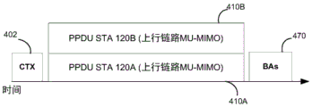
Fig. 4A is a timing diagram illustrating an example of a UL-MU-MIMO protocol 400 that may be used for UL communications. As shown in fig. 4A in conjunction with fig. 1, AP 110 may send a clear to transmit (CTX) message 402 to STAs 120 to indicate which STAs may participate in the UL-MU-MIMO scheme so that a particular STA knows to begin UL-MU-MIMO. In some embodiments, the CTX message may be transmitted in a payload portion of a Physical Layer Convergence Protocol (PLCP) protocol data unit (PPDU). Examples of CTX frame structures are described more fully below with reference to fig. 12-15.
Once STA120 receives CTX message 402 from AP 110 listing the STA, the STA may send UL-MU-MIMO transmission 410. In fig. 4A, STA 120A and STA 120B transmit UL-MU- MIMO transmissions 410A and 410B that contain a Physical Layer Convergence Protocol (PLCP) protocol data unit (PPDU). Upon receiving the UL-MU-MIMO transmission 410, the AP 110 may send a Block Acknowledgement (BA)470 to the STA 120.
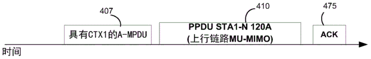
Fig. 4B is a timing diagram illustrating an example of a UL-MU-MIMO protocol that may be used for UL communications. In fig. 4B, CTX frames are aggregated in an aggregate MAC protocol data unit (a-MPDU) message 407. The a-MPDU message 407 may provide the STA120 with time to process before transmitting the UL signal or may allow the AP 110 to transmit data to the STA120 before receiving uplink data.
Not all APs or STAs 120 may support UL-MU-MIMO or UL-FDMA operation. The capability indication from the STA120 may be indicated in a high-efficiency wireless (HEW) capability element included in the association request or the probe request, and may include a bit indication capability, a maximum number of spatial streams that the STA120 can use in UL-MU-MIMO transmission, a frequency that the STA120 can use in UL-FDMA transmission, minimum and maximum powers and granularities in power backoff, and minimum and maximum time adjustments that the STA120 can perform.
The capability indication from the AP may be indicated in a HEW capability element included in an association response, beacon, or probe response, and may include a bit indication capability, a maximum number of spatial streams that a single STA120 can use in UL-MU-MIMO transmissions, a frequency that a single STA120 can use in UL-FDMA transmissions, a required power control granularity, and required minimum and maximum time adjustments that the STA120 should be able to perform.
In one embodiment, capable STA120 may request that a capable AP be part of the UL-MU-MIMO (or UL-FDMA) protocol by sending a management frame to the AP indicating a request to enable use of the UL-MU-MIMO feature. In an aspect, the AP 110 may respond by granting use of the UL-MU-MIMO feature or rejecting it. Once the UL-MU-MIMO is authorized for use, the STA120 may expect CTX messages 402 at various times. In addition, once the STA120 is enabled to operate the UL-MU-MIMO features, the STA120 may be amenable to following a particular mode of operation. If multiple modes of operation are possible, the AP may indicate to the STA120 which mode to use in the HEW capability element, management frame, or operational element. In one aspect, the STA120 is able to dynamically change operating modes and parameters during operation by transmitting different operational elements to the AP 110. On the other hand, the AP 110 may dynamically switch the operation mode during operation by transmitting updated operation elements or management frames to the STAs 120 or in beacons. In another aspect, the operating mode may be indicated in the setup phase and may be set for each STA120 or for groups of STAs 120. In another aspect, the mode of operation may be specified for a per Traffic Identifier (TID).
Fig. 5 is a timing diagram illustrating an example of an operation mode of UL-MU-MIMO transmission in conjunction with fig. 1. In this embodiment, STA120 receives CTX message 402 from AP 110 and sends an immediate response to AP 110. The response may be in the form of a Clear To Send (CTS)408 or another similar signal. In an aspect, the requirement to send a CTS may be indicated in CTX message 402 or may be indicated in a setup phase of the communication. As shown in fig. 5, STA 120A and STA 120B may transmit CTS 1408A and CTS 2408B messages in response to receiving CTX message 402. The Modulation and Coding Scheme (MCS) of CTS 1408A and CTS 2408B may be based on the MCS of CTX message 402. In this embodiment, CTS 1408A and CTS 2408B contain the same bits and the same scrambling sequence so that they may be transmitted to AP 110 at the same time. The duration field of the CTS 408 signal may be based on the duration field in CTX by removing the time of the CTX PPDU. UL-MU- MIMO transmissions 410A and 410B are then transmitted by STAs 120A and 120B as listed in the CTX 402 signal. AP 110 may then send an Acknowledgement (ACK) signal to STAs 120A and 120B. In some aspects, the ACK signal may be a serial ACK signal to each station or BA. In some aspects, ACKs may be polled. This embodiment yields efficiency by sending CTS 408 signals from multiple STAs to the AP 110 simultaneously rather than sequentially, which saves time and reduces the likelihood of interference.
Fig. 6 is a timing diagram illustrating another example of an operation mode of UL-MU-MIMO transmission in conjunction with fig. 1. In this embodiment, STAs 120A and 120B receive CTX message 402 from AP 110 and are allowed to start and UL-MU-MIMO transmission at time (T)406 after the end of the PPDU carrying CTX message 402. T406 may be a short interframe space (SIFS), a point interframe space (PIFS), or another time that may be adjusted with an additional offset indicated by AP 110 in CTX message 402 or via a management frame. The SIFS and PIFS times may be fixed in the standard or indicated by the AP 110 in the CTX message 402 or in a management frame. The benefit of T406 may be to improve synchronization or to allow STAs 120A and 120B time to process CTX message 402 or other messages prior to transmission.
Referring to fig. 4-6, in conjunction with fig. 1, UL-MU-MIMO transmissions 410 may have a common time duration. The duration of the UL-MU-MIMO transmission 410 for STAs utilizing UL-MU-MIMO features may be indicated in the CTX message 402 or during a setup phase. To generate a PPDU of a required duration, the STA120 may construct a PLCP Service Data Unit (PSDU) such that the length of the PPDU matches the length indicated in the CTX message 402. In another aspect, the STA120 may adjust a level of data aggregation in a Medium Access Control (MAC) protocol data unit (a-MPDU) or a level of data aggregation in a MAC service data unit (a-MSDU) to approach a target length. In another aspect, the STA120 may add an end of file (EOF) padding delimiter to reach the target length. In another approach, a pad or EOF pad field is added at the beginning of an a-MPDU. One of the benefits of having all UL-MU-MIMO transmissions of the same length is that the power level of the transmission will remain unchanged.
In some embodiments, the STA120 may have data to upload to the AP, but the STA120 has not received a CTX message 402 or other signal indicating that the STA120 may begin UL-MU-MIMO transmission.
In one mode of operation, STA120 may not transmit outside of a UL-MU-MIMO transmission opportunity (TXOP) (e.g., after CTX message 402). In another mode of operation, STAs 120 may send frames to initialize UL-MU-MIMO transmissions and may then transmit during UL-MU-MIMO TXOPs, e.g., if they are instructed to do so in CTX message 402. In one embodiment, the frame that initiates the UL-MU-MIMO transmission may be a request to send (RTX), a frame designed specifically for this purpose (examples of RTX frame structures are described more fully below with reference to fig. 8 and 9). The RTX frame may be the only frame that allows the STA120 to be used to initiate an UL MU MIMO TXOP. In one embodiment, the STA may not transmit outside the UL-MU-MIMO TXOP, except by transmitting the RTX. In another embodiment, the frame that initiates a UL MU MIMO transmission may be any frame that indicates to the AP 110 that the STA120 has data to send. These frames may be negotiated in advance to indicate UL MU MIMO TXOP requests. For example, the following may be used to indicate that STA120 has data to transmit and is requesting an UL MU MIMO TXOP: request To Send (RTS), data frame or quality of service (QoS) null frame with QoS control frame of 8-15 bits set to indicate more data, or Power Save (PS) poll. In one embodiment, the STA may not transmit outside of the UL MU MIMO TXOP, except by transmitting a frame to trigger the TXOP, which may be an RTS, PS-poll, or QOS null frame. In another embodiment, a STA may transmit single-user uplink data as usual and may indicate a request for an UL MU MIMO TXOP by setting a bit in a QoS control frame of its data packet. Fig. 7 is a timing diagram illustrating an example where a frame initializing UL-MU-MIMO is RTX 701 in connection with fig. 1. In this embodiment, STA120 sends RTX 701 to AP 110, which includes information about UL-MU-MIMO transmissions. As shown in fig. 7, AP 110 may respond to RTX 701 with CTX message 402 authorizing a UL-MU-MIMO TXOP to send UL-MU-MIMO transmission 410 immediately after CTX message 402. In another aspect, the AP 110 may respond with a CTS authorizing a Single User (SU) UL TXOP. In another aspect, AP 110 may respond with a frame (e.g., an ACK or CTX with a special indication) that acknowledges receipt of RTX 701 but does not grant an immediate UL-MU-MIMO TXOP. In another aspect, AP 110 may respond with a frame that acknowledges receipt of RTX 701, does not grant an immediate UL-MU-MIMO TXOP, but grants a delayed UL-MU-MIMO TXOP and may identify the time at which the TXOP is granted. In this embodiment, AP 110 may send CTX message 402 to start UL-MU-MIMO at the authorized time.
In another aspect, AP 110 may respond to RTX 701 with an ACK or other response signal that does not grant UL-MU-MIMO transmission to STA120, but indicates that STA120 should wait a period of time (T) before attempting another transmission (e.g., sending another RTX). In this regard, the time (T) may be indicated by the AP 110 in a setup phase or a response signal. In another aspect, AP 110 and STA120 may agree on a time at which STA120 may send RTX 701, RTS, PS poll, or any other request for UL-MU-MIMO TXOP.
In another mode of operation, the STA120 may send a request for UL-MU-MIMO transmission 410 according to a conventional contention protocol. In another aspect, the contention parameter for STAs 120 that use UL-MU-MIMO is set to a different value than other STAs that do not use the UL-MU-MIMO feature. In this embodiment, the AP 110 may indicate the value of the contention parameter in a beacon, an association response, or through a management frame. In another aspect, the AP 110 may provide a delay timer that prevents the STA120 from transmitting after each successful UL-MU-MIMO TXOP or for some amount of time after each RTX, RTS, PS poll, or QoS null frame. The timer may be restarted after each successful UL-MU-MIMO TXOP. In an aspect, AP 110 may indicate the delay timer to STA120 during the setup phase, or the delay timer may be different for each STA 120. In another aspect, the AP 110 may indicate the delay timer in the CTX message 402 or the delay timer may depend on the order of the STAs 120 in the CTX message 402, and the delay timer may be different for each terminal.
In another mode of operation, the AP 110 may indicate a time interval during which the STA120 is allowed to send UL-MU-MIMO transmissions. In an aspect, AP 110 indicates to STA120 a time interval during which the STA is allowed to send an RTX or RTS or other request to AP 110 to request an UL-MU-MIMO transmission. In this regard, the STAs 120 may use a conventional contention protocol. In another aspect, the STA may not initiate UL-MU-MIMO transmissions during the time interval, but the AP 110 may send a CTX or other message to the STA to initiate UL-MU-MIMO transmissions.
In certain embodiments, an STA120 enabled for UL-MU-MIMO may indicate to the AP 110 that it is requesting an UL-MU-MIMO TXOP because it has pending data for the UL. In an aspect, STA120 may send an RTS or PS poll to request an UL-MU-MIMO TXOP. In another embodiment, the STA120 may transmit any data frame including a quality of service (QoS) null data frame, where an 8-15 bit QoS control field indicates a non-null queue. In this embodiment, the STA120 may determine during the setup phase which data frames (e.g., RTS, PS-poll, QoS null frames, etc.) will trigger UL-MU-MIMO transmissions when the 8-15 bit QoS control field indicates a non-empty queue. In one embodiment, the RTS, PS-poll, or QoS null frame may include a 1-bit indication that allows or disallows the AP 110 to respond with the CTX message 402. In another embodiment, the QoS null frame may include TX power information and per TID queue information. TX power information and per-TID queue information may be inserted into two bytes of the sequence control and QoS control fields in the QoS null frame and the modified QoS null frame may be sent to AP 110 to request an UL-MU-MIMO TXOP. In another embodiment, referring to fig. 1 and 7, STA120 may transmit RTX 701 to request an UL-MU-MIMO TXOP.
In response to receiving an RTS, RTX, PS-poll or QoS null frame or other trigger frame as described above, AP 110 may send CTX message 402. In one embodiment, referring to fig. 7, after transmission of CTX message 402 and completion of UL-MU- MIMO transmissions 410A and 410B, the TXOP returns to STAs 120A and 120B which can decide how to use the remaining TXOP. In another embodiment, referring to fig. 7, after transmission of CTX message 402 and UL-MU- MIMO transmissions 410A and 410B is complete, the TXOP remains with AP 110, and AP 110 may use the remaining TXOP for additional UL-MU-MIMO transmissions by sending another CTX message 402 to STAs 120A and 120B or other STAs.
Fig. 8 is a message timing diagram of one embodiment of multi-user uplink communication. Message exchange 800 illustrates the communication of wireless messages between AP 110 and three stations 120 a-c. The message exchange 800 instructs each STA120 a-c to send a request to send (RTX) message 802a-c to the AP 110. Each RTX message 802a-c indicates that a transmitting station 120a-c has data available to send to AP 110.
After receiving each RTX message 802a-c, the AP 110 may respond with a message indicating that the AP 110 has received an RTX. As shown in fig. 8, the AP 110 sends ACK messages 803a-c in response to each RTX message 802 a-c. In some embodiments, AP 110 may transmit a message (e.g., a CTX message) indicating that each RTX message 802a-c has been received but that AP 110 has not yet granted a transmission opportunity for uplink data by stations 120 a-c. In fig. 8, the AP 110 transmits a CTX message 804 after transmitting the ACK message 803 c. In some aspects, the CTX message 804 is sent to at least the stations STAs 120 a-c. In some aspects, the CTX message 804 is broadcast. In some aspects, CTX message 804 indicates permissions that authorize which stations to send data to AP 110 during a transmission opportunity. In some aspects, the start time of the transmission opportunity and its duration may be indicated in the CTX message 804. For example, the CTX message 804 may indicate that the station STAs 120a-c should set their network allocation vectors to be consistent with a Network Allocation Vector (NAV) 812.
At the time indicated by CTX message 804, three stations 120a-c transmit data 806a-c to AP 110. The data 806a-c is transmitted at least partially simultaneously during the transmission opportunity. The transmission of data 806a-c may utilize uplink multi-user multiple-input multiple-output transmission (UL-MU-MIMO) or uplink frequency division multiple access (UL-FDMA).
In some aspects, stations STAa-c may transmit padding data such that transmissions of each station transmitting during a transmission opportunity have approximately equal durations. Message exchange 800 shows STA120 a transmitting padding 808a and STA120 c transmitting padding 808 c. The transmission of the padding data ensures that the transmissions from each STA120 a-c are completed at approximately the same time. This may provide more balanced transmit power throughout the duration of the transmission, thereby optimizing AP 110 receiver efficiency.
After the AP 110 receives the data transmissions 806a-c, the AP 110 sends acknowledgements 810a-c to each of the stations 120 a-c. In some aspects, the acknowledgments 810a-c may be sent at least partially simultaneously using DL-MU-MIMO or DL-FDMA.
Fig. 9 is a diagram of one embodiment of an RTX frame 900. RTX frame 900 includes a Frame Control (FC) field 910, a duration field 915 (optional), a Transmitter Address (TA)/Assignment Identifier (AID) field 920, a Receiver Address (RA)/Basic Service Set Identifier (BSSID) field 925, a TID field 930, an estimated Transmission (TX) time field 950, and a TX power field 970. The FC field 910 indicates a control subtype or an extension subtype. Duration field 915 indicates to any receiver of RTX frame 900 to set the NAV. In an aspect, the RTX frame 900 may not have a duration field 915. The TA/AID field 920 indicates a source address that can be an AID or a full MAC address. The RA/BSSID field 925 indicates that the RA or BSSID of the STA simultaneously transmits uplink data. In an aspect, the RTX frame may not contain the RA/BSSID field 925. The TID field 930 indicates the Access Category (AC) for which the user has data. The estimated TX time field 950 indicates the time requested for the UL-TXOP and may be the time required for the STA120 to transmit all the data in its buffer at the currently planned MCS. The TX power field 970 indicates the power of the transmitted frame and may be used by the AP to estimate the link quality and adapt the power backoff indicator in the CTX frame.
In some embodiments, the AP 110 may collect information from STAs 120 that may be engaged in UL-MU-MIMO communication before enabling UL-MU-MIMO communication. AP 110 may optimize the collection of information from STAs 120 by scheduling transmissions from STAs 120.
As described above, CTX message 402 may be used for various communications. Fig. 10 is a diagram of an example of a CTX frame 1000 structure. In this embodiment, the CTX frame 1000 is a control frame including a Frame Control (FC) field 1005, a duration field 1010, a Transmitter Address (TA) field 1015, a Control (CTRL) field 1020, a PPDU duration field 1025, a STA info (info) field 1030, and a Frame Check Sequence (FCs) field 1080. The FC field 1005 indicates a control subtype or an extension subtype. The duration field 1010 indicates to any receiver of the CTX frame 1000 to set the NAV. The TA field 1015 indicates the transmitter address or BSSID. CTRL field 1020 is a generic field that may include information regarding the format of the remainder of the frame (e.g., the number of STA info fields and the presence or absence of any subfields within the STA info fields), an indication of rate adaptation for STA120, an indication of allowed TID, and an indication that the CTS must be sent immediately after CTX frame 1000. The indication for rate adaptation may include data rate information, such as an amount indicating how much the STA should reduce its MCS compared to the MCS that the STA would otherwise use in a single user transmission. The CTRL field 1020 may also indicate whether the CTX frame 1000 is used for UL MU MIMO or for UL FDMA or for both UL MU MIMO and UL FDMA, indicating whether there is an Nss or tone allocation field in the STA info field 1030.
Alternatively, the indication of whether CTX is for UL MU MIMO or UL FDMA may be based on the value of the subtype. Note that UL MU MIMO and UL FDMA operations can be jointly performed by specifying spatial streams to be used and channels to be used to STAs, in which case both fields exist in CTX; in this case, the Nss indication is referred to as a specific tone allocation. The PPDU duration 1025 field indicates the duration of the subsequent UL-MU-MIMO PPDU that the STA120 is allowed to transmit. The STA info 1030 field contains information about a particular STA and may include a per-STA (per STA 120) information set (see STA info 11030 and STA info N1075). The STA info 1030 field may include an AID or MAC address field 1032 that identifies the STA, a number of spatial streams field (Nss)1034 field that indicates the number of spatial streams that the STA may use (in a UL-MU-MIMO system), a time adjustment 1036 field that indicates the time the STA should adjust its transmission compared to receiving a trigger frame (in this case CTX), a power adjustment 1038 field that indicates the power backoff the STA should take from the declared transmit power, a tone allocation 1040 field that indicates the tones or frequencies that the STA may use (in a UL-FDMA system), an allowed TID 1042 field that indicates the allowable TID, an allowed TX mode 1044 field that indicates the allowed TX mode, an MCS 1046 field that indicates the MCS the STA should use, and a TX start time field 1048 that indicates the start time for the STA to transmit uplink data. In some embodiments, the allowed TX modes may include a short/long Guard Interval (GI) or cyclic prefix mode, a Binary Convolutional Code (BCC)/Low Density Parity Check (LDPC) mode (typically a coding mode), or a space-time block coding (STBC) mode.
In some embodiments, STA info field 1030-1075 may be excluded from CTX frame 1000. In these embodiments, the CTX frame 1000 missing the STA info field may indicate to the STA120 receiving the CTX frame 1000 that a request message for uplink data (e.g., an RTS, RTX, or QoS null frame) has been received, but that a transmission opportunity has not yet been granted. In some embodiments, control field 1020 may include information about the requested uplink. For example, the control field 1020 may include a latency before sending data or another request, a reason code why the request was not authorized, or other parameters for controlling medium access from the STA 120. The CTX frame missing the STA information field may also be applied to the CTX frame 1100, 1200, 1300, or 1400 described below.
In some embodiments, a STA120 receiving a CTX indicated by allowed TID 1042 may be allowed to send data only for that TID, data of the same or higher TID, data of the same or lower TID, any data, or first only data of that TID, if no data is available, data of other TIDs. The FCS 1080 field indicates that an FCS value for error detection of the CTX frame 1000 is carried.
Fig. 11 is a diagram of another example of a CTX frame 1100 structure. In this embodiment and in conjunction with fig. 10, the STA info 1030 field does not contain the AID or MAC address 1032 field, but rather the CTX frame 1000 includes a Group Identifier (GID)1026 field that identifies STAs by group identifier rather than individual identifier to transmit uplink data simultaneously. Fig. 12 is a diagram of another example of a CTX frame 1200 structure. In this embodiment and in conjunction with fig. 11, the GID 1026 field is replaced with an RA 1014 field that identifies the group of STAs by a multicast MAC address.
Fig. 13 is a diagram of an example of a CTX frame 1300 structure. In this embodiment, the CTX frame 1300 is a management frame including a management MAC header 1305 field, a body 1310 field, and an FCS 1380 field. The body 1310 field includes an IE ID 1315 field that identifies an Information Element (IE), a LEN 1320 field that indicates the length of the CTX frame 1300, a CTRL 1325 field that includes the same information as the CTRL 1020 field, a PPDU duration 1330 field that indicates the duration of a subsequent UL-MU-MIMO PPDU that the STA120 is allowed to transmit, a STA info 11335 field, and an MCS 1375 field that can indicate an MCS for all STAs to use for subsequent UL-MU-MIMO transmissions, or an MCS backoff for all STAs to use for subsequent UL-MU-MIMO transmissions. The STA info 11335 (along with STA info N1370) fields represent per-STA fields that include an AID 1340 field that identifies the STA, a number of spatial streams field (Nss)1342 field that indicates the number of spatial streams that the STA may use (in a UL-MU-MIMO system), a time adjustment 1344 field that indicates the time at which the STA should adjust its transmit time compared to the receive trigger frame (CTX in this case), a power adjustment 1348 field that indicates the power backoff the STA should take from the asserted transmit power, a tone allocation 1348 field that indicates the tones or frequencies that the STA may use (in a UL-FDMA system), an allowed TID 1350 field that indicates the allowable TID, and a TX start time field 1048 that indicates the start time for the STA to transmit uplink data.
In one embodiment, CTX frame 1000 or CTX frame 1300 may be aggregated in an a-MPDU to provide STA120 with time to process before transmitting the UL signal. In this embodiment, padding or data may be added after the CTX to allow STA120 additional time to process the upcoming packet. One benefit of padding the CTX frame may be to avoid possible contention issues for UL signals from other STAs 120, as compared to increasing the inter-frame space (IFS) as described above. In one aspect, if the CTX is a management frame, an additional padding Information Element (IE) may be transmitted. In one aspect, additional a-MPDU padding delimiters may be included if CTXs are aggregated in an a-MPDU. The padding delimiter can be an EoF delimiter (4 bytes) or other padding delimiters. On the other hand, padding may be achieved by adding data, controlling or managing the MPDPU as long as they do not need to be processed within the IFS response time. The MPDU may include an indication that an immediate response is not required and will not be required by any subsequent MPDUs to the receiver. In another aspect, STA120 may request a minimum duration or padding of CTX frames from AP 110. In another embodiment, padding may be achieved by adding PHY OFDMA symbols, which may include undefined bits that do not carry information, or may include bit sequences that carry information, as long as they do not need to be processed within the IFS time.
In some embodiments, AP 110 may initiate a CTX transmission. In one embodiment, AP 110 may transmit CTX message 402 according to a conventional Enhanced Distributed Channel Access (EDCA) contention protocol. In another embodiment, AP 110 may transmit CTX message 402 at a scheduled time. In this embodiment, the scheduled time may be indicated to the STAs 120 by the AP 110 by using a Restricted Access Window (RAW) indication in the beacon indicating the time reserved for the group of STAs 120 to access the medium, a Target Wake Time (TWT) agreement with each STA120 indicating to wake multiple STAs 120 simultaneously to participate in UL-MU-MIMO transmissions, or information in other fields. In addition to RAW and TWT, the STA120 may be allowed to transmit any frame or only a subset of frames (e.g., non-data frames). It may also be prohibited from sending certain frames (e.g., it may be prohibited from sending data frames). STA120 may also indicate that it is in a sleep state. One advantage of scheduling CTXs is that multiple STAs 120 may be indicated the same TWT or RAW time and may receive transmissions from the AP 110.
Fig. 14 is a diagram of an example of a structure of a CTX frame 1400. The CTX frame 1400 may be transmitted by an AP to one or more STAs, such as one or more of the AP 110 and STAs 120a-i of fig. 1. For example, the CTX frame 1400 may be transmitted according to one or more of the timing diagrams of FIGS. 4A, 4B, or 5-8. In various embodiments, the CTX frame 1400 may be transmitted to one or more STAs 120 to provide parameters of an uplink response message to be transmitted by the one or more STAs 120 in response to the CTX frame 1400. As shown, the CTX frame 1400 includes an FC field 1402, a duration field 1404, a first address ("a 1") field 1406, a second address ("a 2") field 1408, a common information field 1410, a per-user information field 1450-.
The FC field 1402 may indicate a control subtype or an extension subtype. The duration field 1404 can indicate to the receiver of the CTX frame 1400 to set the NAV based on the indicated value. The a1 field 1406 can indicate an address, BSSID, or other identifier of a device (e.g., a group of STAs) intended to receive the CTX message, such as one or more of the STAs 120. In some aspects, the a1 field 1406 may be optional, such as when the CTX frame 1400 is broadcast. The a2 field 1408 can indicate the address, BSSID, or other identifier of the device that sent the CTX message, such as AP 110.
The common information field 1410 may include information about the format of the remainder of the frame (e.g., the number of STA info fields and the presence or absence of any sub-fields within the STA info field), an indication for rate adaptation by the STA120, an indication of allowed TIDs, an indication that a CTS must be sent immediately after the CTX frame 1400, etc. For example, as shown, the common information field 1410 can include a duration field 1412, a packet extension field 1414, an LTF type field 1416, a Cyclic Prefix (CP) field 1418, a response Bandwidth (BW) field 1420, a power control field 1422, a resource allocation map field 1424, a carrier sense field 1426, a TID/Traffic Class (TC) field 1428, a random access field 1430, a response type field 1432, an aggregation control field 1434, a backoff field 1436, a Negative Acknowledgement (NACK) field 1438, a BSS color field 1440, a TXOP duration field 1442, and a RL-SIG mask sequence field 1444. In some aspects, the duration field 1412, packet extension field 1414, LTF type field 1416, CP field 1418, response BW field 1420, power control field 1422, and resource allocation map field 1424 may be referred to as PHY parameters. In some aspects, some of these parameters can be used by the STA120 to form an uplink response packet (e.g., an UL MU PPDU), and/or can be included in the SIG-a field of the uplink response packet. Additionally or alternatively, in some aspects, the CTX frame 1400 may include a field indicating the exact value to be used in the SIG-a field. According to these aspects, the STA120 can simply copy the contents of this field into the transmitted SIG-a in the uplink response message. In some aspects, this mode can simplify operation of the STA120, and can also facilitate updating of the SIG-a content format. In some aspects, the carrier sense field 1426, TID/TC field 1428, random access field 1430, response type field 1432, aggregation control field 1434, backoff field 1436, and NACK field 1438 may be referred to as MAC parameters. While all of these fields are shown as being part of common information field 1410, only a portion of these fields may be present, additional fields may be present, and the ordering of the fields may be rearranged in a given embodiment.
The duration field 1412 may indicate the number of OFDM symbols from the STA120 that respond to the PSDU (e.g., uplink packet). In some aspects, the duration field 1412 may be nine bits in length. In another aspect, the duration field 1412 may be nine bits. In other aspects, duration field 1412 may be more or less than 9 bits in length. In some aspects, the OFDM symbol may be 16 μ β, such as the symbol duration in IEEE 802.11 ax. In other aspects, the OFDM symbol may be 4 μ β, such as the symbol duration in IEEE 802.11 ac. According to these aspects, a trigger may be used to trigger a non-High Efficiency (HE) Single User (SU) PPDU without loss due to padding. In another aspect, if the uplink response message (e.g., UL MU PPDU), the duration field 1412 may include a value for each STA to copy into the length field of the L-SIG field. According to this aspect, the duration field 1412 may be set according to rules defined for the setting of the length field in the L-SIG field according to one or more of the 802.11 specifications. In various aspects, the duration field 1412 may indicate a duration in a symbol of a PPDU or MPDU to be received from the STA120 (e.g., an uplink packet). The packet extension field 1414 can indicate whether the STA120 must consider or include Packet Extension (PE) symbols at the end of the responsive PPDU, or otherwise use PE techniques. In some embodiments, the PE may allow a device receiving a packet to have additional processing time to accurately process the information contained in the packet. In some aspects, packet extension field 1414 may indicate one or more of an a-factor, LDPC extra symbols, or PE duration. The a-factor may be similar to the a-factor described in U.S. provisional application No.62/189,170. In some aspects, the length of the a-factor may be three bits or less. The LDPC extra symbol may be one bit in length and may be used to indicate whether an additional symbol for LDPC should be used in an uplink response message of the STA. The length of the PE duration may be three bits and may indicate an extended duration to be added to the end of the uplink packet transmitted by the STA 120. In some aspects, the PE duration may be 1 or 0 μ s, 4 μ s, 8 μ s, 12 μ s, or 16 μ s.
The LTF type field 1416 may indicate whether a long or short LTF format is to be used for the uplink response message. In some aspects, the LTF type field 1416 may additionally or alternatively indicate a total duration or length of LTFs to be used for the uplink response message. The indication of the total duration of the LTFs may be useful because one or more of the STAs 120 may use different numbers of spatial streams, and it is beneficial if the number of LTFs (or total duration) is the same among the STAs 120. The CP field 1418 may be two bits in length and may indicate the duration of the CP to be used in the uplink response message. In some aspects, there may be three different CP modes. The response BW field 1420 may indicate which portion of BW should be used by the STA120 for the legacy preamble of the uplink response message. In some aspects, the indicated portion may be the entire BW available or a portion thereof.
The carrier sense field 1426 may indicate whether the STA120 is to consider channel conditions (e.g., physical carrier sensing and virtual carrier sensing) before responding with the uplink response message. For example, carrier sense field 1426 may include a one bit indication of whether STA120 must sense whether the transmission medium is sufficiently free from transmission. In some aspects, the sensing may be performed in accordance with an energy detection technique, a packet detection technique, or some other technique. In some aspects, the carrier sense field may also indicate a Clear Channel Assessment (CCA) threshold for the STA 120. In accordance with these aspects, the STA120 may determine whether the medium is sufficiently idle based at least in part on whether the strength of the information sensed on the medium is above or below a threshold.
The TID/TC field 1428 may indicate one or more of a traffic identifier or a traffic class that the STA120 must use for the uplink response message. The random access field 1430 may indicate that some resource units are allocated for random access. For example, in some embodiments, AP 110 may provide one or more resource units for STAs to transmit information to AP 110 according to a contention-based protocol. The parameters of the random access RU may be indicated in the response type field 1432 or the per-user information field 1450-. The response type field 1432 may indicate the type or subtype of message/frame that the STA120 must send in the uplink response message. For example, the response type field 1432 may indicate that any MPDU type may be utilized, that each STA120 must respond with a legacy CTS, that each STA is to respond with a HE CTS response, or some combination thereof. If a random access RU is used, the response type field 1432 may indicate that only frame types that do not require carrier sensing may be used, that only frames may be sent during the random access RU that are a retransmission of a previously applied transmission within a particular time frame, that only packets of a particular type or subtype may be sent (e.g., only encrypted packets), that only associated STAs 120 may be sent during the random access RU, that only non-associated STAs 120 may be sent during the random access RU, a priority of the device (or type of device), or some combination thereof. For example, during the random access RU, the STA120 may send various types of frames such as PS-Poll/QoS null frames, data, compressed beamforming report feedback, legacy CTS, etc.
The aggregation control field 1434 may indicate the presence of additional aggregation (a) control fields or subfields. In some aspects, the aggregation control field 1434 may also indicate the type of a control field that is present. In some aspects, the a control subfield may include a Channel Quality Indication (CQI) request parameter, a buffer request parameter (e.g., a status request, which may request only information about the next buffered transmission or may request information about all transmissions buffered by STA 120), a medium reuse parameter (e.g., a CCA delay threshold, an interference limit, an SNR requirement, etc.), an ACK/BA (e.g., if unicast CTX frame 1400) or an indication that a Tunneled Direct Link Station (TDLS) may be utilized (e.g., for one STA120 to transmit to another STA120 and not just to AP 110).
The backoff field 1436 may indicate the backoff behavior of the STA120 after receiving the CTX frame 1400 or after the STA120 transmits an uplink response message. For example, the backoff field 1436 may indicate whether the STAs 120 are to reset their backoff, keep them backoff, or otherwise may provide a new contention window value. In some aspects, backoff may be used for fairness (e.g., fairness in accessing a wireless medium). The NACK field 1438 may indicate whether the STA120 must transmit MPDUs even if the STA120 does not have content to transmit (e.g., for the type of response allowed). In some aspects, STAs 120 that do not have content to transmit may transmit quality of service (QoS) null packets. In some aspects, the STA120 may need to pad the MPDUs transmitted in this case to reach the requested response duration. BSS color field 1440 may indicate an AP 110 color or a multi-BSS color. The TXOP duration field 1442 may be used to set the NAV. The RL-SIG mask sequence field 1444 may be used to indicate the type of mask to be applied in the RL-SIG field of the uplink response message.
As shown, the per-user information field 1450-SS) A field 1474, a spatial stream start index 1476, a MU-MIMO field 1478, a power control field 1480, a timing adjustment field 1482, and a frequency offset adjustment field 1484. In some aspects, address type field 1452, address field 1454, response type field 1456, aggregation control field 1458, ACK/BA field 1460, NACK field 1462, and TID/TC field 1464 may be referred to as MAC parameters. In some aspects, MCS field 1466, DCM field 1468, BCC/LDPC field 1470, RU index field 1472, NSSField 1474, spatial stream start index 1476, MU-MIMO field 1478, power control field 1480, timing adjustment field 1482, and frequency adjustment field 1484 may be referred to as PHY parameters.
The address type field 1452 may include a one-bit indication of whether the address field 1454 contains an AID or MAC address of the identified STA 120. The address field 1454 can contain the AID, MAC address, or hash of the MAC address of the STA120 for which the information in the per-user information field 1450 is intended (hereinafter referred to as "identified STA 120"). In some aspects, if AID is used, the address field 1454 may be twelve bits (or less). In some aspects, the address field 1454 may be greater than or equal to twelve bits if a MAC address is used. In some aspects, a hash of the MAC address of the STA120 may be used for non-associated STAs 120, as there may be no AIDs available.
The response type field 1456 may indicate the type of message/packet that the identified STA120 is to use for the uplink response message. For example, the response type field 1456 may indicate that any MPDU type may be used, that sounding feedback may only be provided, that PS polls may only be sent, or some combination thereof. Aggregation control field 1458 may indicate the presence of an a control field. In some aspects, the a control field may include one or more of a BA request (BAR), a CQI request, a buffer information request, a Channel State Information (CSI) segment/channel, or some combination thereof. In some aspects, the CSI segments/channels may indicate parameters to be used for sounding feedback responses. In some aspects, the aggregation control field 1458 may also indicate the type of a control field that is present.
The ACK/BA field 1460 may indicate an ACK/BA type for fragmentation. Similar to the NACK field 1438 described above, the NACK field 1462 may indicate that a NACK is requested, but is based on the individual STA 120. The TID/TC field 1464 may indicate one or more of a traffic identifier or a traffic class that the identified STA120 must use for an uplink response message. The MCS field 1466 may indicate an MCS to be used by the identified STA120 for the uplink response message. DCM field 1468 may indicate a DCM to be used by the identified STA120 when responding. The BCC/LDPC field 1470 may indicate the BCC/LDPC response coding type for the identified STA 120.
RU index field 1472 may indicate the RU allocated for the identified STA 120. In some aspects, RU index field 1472 may indicate log2(# RU), where # RU represents the number of RUs allocated for the identified STA 120. In some aspects, the RU index may indicate a starting RU and indicate a number of consecutive RUs allocated for the identified STA 120. N is a radical ofSSA field 1474 may indicate the number of spatial streams allocated for the identified STA120, and a spatial stream start index 1476 may indicate a start index of the allocated spatial streams. The MU-MIMO field 1478 may indicate whether MU-MIMO is to be used. In some aspects, if MU-MIMO is not used, other related fields, such as the power control field 1480, may not be present within the CTX message. Power control field 1480 can indicate the transmit power of the identified STA120 or the expected received power (by AP 110) from STA 120. In some aspects, the identified STAs 120 may calculate their transmit power based at least in part on the information. Timing adjustment field 1482 may indicate a timing adjustment for the identified STA120 that can allow AP 110 to correct for different arrival times between STAs 120. Frequency offset adjustment field 1484 may indicate a frequency adjustment for the identified STA120 that can allow AP 110 to correct for different center frequency settings between STAs 120.The per-user information field 1490 may contain fields similar to those described above, but may contain more or fewer fields, depending on the particular STA120 identified. The FCS field 1495 can indicate an FCS value used for error detection of the CTX frame 1400.
Fig. 15 is a flow diagram of an example method 1500 for wireless communication in accordance with certain embodiments described herein. One of ordinary skill in the art will appreciate that the method 1500 may be implemented by any suitable device and system. For example, the method 1500 may be implemented by the AP 110 of fig. 1.
In operation block 1505, the method 1500 includes generating a clear to transmit (CTX) message indicating an uplink transmission opportunity, the CTX message further including a request for two or more stations to simultaneously transmit uplink data at a particular time. In some aspects, the two or more stations include two or more of the STAs in fig. 1. In an embodiment, the CTX message may be similar to the CTX frame 1400 of fig. 14. In some aspects, the CTX message can include a common information field including information common to all of the two or more stations and two or more individual information fields respectively corresponding to each of the two or more stations. In some aspects, the CTX message can include a 9-bit duration field indicating a number of OFDM symbols to be used for multiple uplink data transmissions. In some aspects, the CTX message can include an indication of whether two or more stations are to include a packet extension symbol at the end of the plurality of uplink data transmissions. In some aspects, the CTX message can include an indication that two or more stations are to consider a state of a wireless medium prior to transmission, and an indication of a clear channel assessment threshold to be used by the two or more stations in considering the state of the wireless medium. In some aspects, the CTX message can include an indication of a packet type used by two or more stations for multiple uplink data transmissions, and an indication of whether associated or non-associated stations may transmit during an uplink transmission opportunity. In some aspects, the CTX message can include an indication of a transmit power of the CTX message and a target receive power for a plurality of uplink data transmissions. In some aspects, generating the clear to send message may include allocating a portion of memory for the message and initializing the allocated memory in a format consistent with the format of the CTX message (e.g., any of the message formats shown in fig. 10-14).
In operation block 1510, the method 1500 further comprises transmitting the CTX message to the two or more stations. Transmitting the CTX message to the two or more stations may include setting at least transmission address information of the CTX message to identify the two or more stations, for example, via station or MAC addresses of the two or more stations. Sending a CTX message may also include invoking a send function in a network software driver or passing data to a network hardware chip (e.g., transmitter 310). When the network software driver is invoked or data is passed to the network hardware chip, a portion of the memory initialized with the message format of the CTX message may be identified to the network software driver or the network hardware chip via the input parameters.
In operation block 1515, the method 1500 further includes receiving a plurality of uplink data transmissions from at least two of the two or more stations at the particular time. In some aspects, receiving the plurality of uplink data transmissions may include receiving a notification from a network hardware chip that one or more packets have been received from the network and copying packet data from the network hardware chip to a memory, such as memory 306 shown in fig. 3.
In some aspects, the method 1500 may further include determining one or more resource units for random access, including an indication of the one or more resource units in the CTX message, and receiving random access uplink data based on the one or more resource units.
In some embodiments, an apparatus for wireless communication may perform some functions of method 1500. The apparatus includes means for generating a clear to transmit (CTX) message indicating an uplink transmission opportunity, the CTX message further including a request for two or more stations to simultaneously transmit uplink data at a particular time. In some aspects, the means for generating may include one or more of the processor 304, the memory 306, or equivalents thereof. The apparatus may also include means for transmitting the CTX message to two or more stations. In some aspects, means for transmitting may include one or more of transmitter 310, transceiver 314, or equivalents thereof. The apparatus may also include means for receiving a plurality of uplink data transmissions from at least two of the two or more stations at a particular time. In some aspects, the means for receiving may include one or more of the receiver 312, the transceiver 314, or equivalents thereof.
Those of skill in the art would understand that information and signals may be represented using any of a variety of different technologies and techniques. For example, data, instructions, commands, information, signals, bits, symbols, and chips that may be referenced throughout the above description may be represented by voltages, currents, electromagnetic waves, magnetic fields or particles, optical fields or particles, or any combination thereof.
Various modifications to the embodiments described in this disclosure will be readily apparent to those skilled in the art, and the generic principles defined herein may be applied to other embodiments without departing from the spirit or scope of the disclosure. Thus, the present disclosure is not intended to be limited to the embodiments shown herein but is to be accorded the widest scope consistent with the claims, principles and novel features disclosed herein. The word "exemplary" is used exclusively herein to mean "serving as an example, instance, or illustration. Any embodiment described herein as "exemplary" is not necessarily to be construed as preferred or advantageous over other embodiments.
Certain features that are described in this specification in the context of separate embodiments can also be implemented in combination in a single embodiment. Conversely, various features that are described in the context of a single embodiment can also be implemented in multiple embodiments separately or in any suitable subcombination. Furthermore, although features may be described above as acting in certain combinations and even initially claimed as such, one or more features from a claimed combination can in some cases be excised from the combination, and the claimed combination may be directed to a subcombination or variation of a subcombination.
The various operations of the methods described above may be performed by any suitable means capable of performing the operations, such as various hardware and/or software components, circuits, and/or modules. Generally, any operations shown in the figures can be performed by corresponding functional units capable of performing the operations.
The various illustrative logical blocks, modules, and circuits described in connection with the disclosure may be implemented or performed with a general purpose processor, a Digital Signal Processor (DSP), an Application Specific Integrated Circuit (ASIC), a field programmable gate array signal (FPGA) or other Programmable Logic Device (PLD), discrete gate or transistor logic, discrete hardware components, or any combination thereof designed to perform the functions described herein. A general purpose processor may be a microprocessor, but in the alternative, the processor may be any commercially available processor, controller, microcontroller or state machine. A processor may also be implemented as a combination of computing devices, e.g., a combination of a DSP and a microprocessor, a plurality of microprocessors, one or more microprocessors in conjunction with a DSP core, or any other such configuration.
In one or more aspects, the functions described may be implemented in hardware, software, firmware, or any combination thereof. If implemented in software, the functions may be stored on or transmitted over as one or more instructions or code on a computer-readable medium. Computer-readable media includes both computer storage media and communication media including any medium that facilitates transfer of a computer program from one place to another. A storage media may be any available media that can be accessed by a computer. By way of example, and not limitation, such computer-readable media can comprise RAM, ROM, EEPROM, CD-ROM or other optical disk storage, magnetic disk storage or other magnetic storage devices, or any other medium that can be used to carry or store desired program code in the form of instructions or data structures and that can be accessed by a computer. Also, any connection is properly termed a computer-readable medium. For example, if the software is transmitted from a website, server, or other remote source using a coaxial cable, fiber optic cable, twisted pair, Digital Subscriber Line (DSL), or wireless technologies such as infrared, radio, and microwave, then the coaxial cable, fiber optic cable, twisted pair, DSL, or wireless technologies such as infrared, radio, and microwave are included in the definition of medium. Disk and disc, as used herein, includes Compact Disc (CD), laser disc, optical disc, Digital Versatile Disc (DVD), floppy disk and blu-ray disc where disks usually reproduce data magnetically, while discs reproduce data optically with lasers. Thus, in some aspects, computer-readable media may comprise non-transitory computer-readable media (e.g., tangible media). Additionally, in some aspects, computer readable media may include transitory computer readable media (e.g., signals). Combinations of the above should also be included within the scope of computer-readable media.
The methods disclosed herein comprise one or more steps or operations for carrying out the methods. Method steps and/or operations may be interchanged with one another without departing from the scope of the claims. That is, unless a specific order of steps or operations is specified, the order and/or use of specific steps and/or operations may be modified without departing from the scope of the claims.
Further, it should be appreciated that modules and/or other suitable means for performing the methods and techniques described herein may be downloaded and/or otherwise obtained as appropriate by a wireless station and/or a base station. For example, such a device can be coupled to a server to facilitate transmitting means for performing the methods described herein. Alternatively, the various methods described herein can be provided via a storage unit (e.g., RAM, ROM, a physical storage medium such as a Compact Disc (CD) or floppy disk, etc.), such that the various methods are available to the wireless station and/or base station when the storage unit is coupled to or provided to the device. Further, any other suitable technique for providing the methods and techniques described herein to a device may be utilized.
While the foregoing is directed to aspects of the present disclosure, other and further aspects of the disclosure may be devised without departing from the basic scope thereof, and the scope thereof is determined by the claims that follow.
Claims (28)
1. An apparatus for wireless communication, comprising:
an electronic hardware processor configured to generate a clear to send message comprising a first indication of an uplink transmission opportunity, the clear to transmit message further includes a request for two or more stations to simultaneously transmit uplink data at a particular time, the clear to transmit message further comprises a common information field comprising information common to all of the two or more stations, the clear to transmit message further includes two or more individual information fields corresponding to each of the two or more stations, respectively, the clear to transmit message further includes a duration field indicating a length of a plurality of uplink data transmissions to be received from the two or more stations at the particular time, wherein the indicated length corresponds to a number of orthogonal frequency division multiplexing symbols;
a transmitter configured to transmit the clear to transmit message to the two or more stations; and
a receiver configured to receive the plurality of uplink data transmissions from at least two stations of the two or more stations at the particular time.
2. The apparatus of claim 1, wherein the duration field comprises 9 bits.
3. The apparatus of claim 1, wherein the electronic hardware processor is further configured to generate the clear to transmit message to include an indication of whether the two or more stations are to include a packet extension symbol at an end of the plurality of uplink data transmissions.
4. The apparatus of claim 1, wherein the electronic hardware processor is further configured to generate the clear to transmit message to include a second indication that the two or more stations are to consider a state of a wireless medium prior to transmitting, and wherein the clear to transmit message further includes a third indication of a clear channel assessment threshold to be used by the two or more stations in considering the state of the wireless medium.
5. The apparatus of claim 1, wherein:
the electronic hardware processor is further configured to determine one or more resource units for random access and include an indication of the one or more resource units in the clear to send message, an
The receiver is further configured to receive random access uplink data based on the one or more resource units.
6. The apparatus of claim 1, wherein the electronic hardware processor is further configured to generate the clear to transmit message to include a second indication of a packet type to be used by the two or more stations for the plurality of uplink data transmissions and a third indication of whether associated or non-associated stations are capable of transmitting during the uplink transmission opportunity.
7. The apparatus of claim 1, wherein the electronic hardware processor is further configured to generate the clear to transmit message to include a second indication of a transmit power of the clear to transmit message and a target receive power for the plurality of uplink data transmissions.
8. A method for wireless communication, comprising:
generating, via an electronic hardware processor, a clear to transmit message indicating an uplink transmission opportunity and a request for two or more stations to simultaneously transmit uplink data at a particular time, the clear to transmit message further comprising a common information field including information common to all of the two or more stations, the clear to transmit message further comprising two or more individual information fields, the two or more individual information fields corresponding to each of the two or more stations, respectively, the clear to transmit message further comprising a duration field for indicating a length of a plurality of uplink data transmissions to be received from the two or more stations at the particular time, wherein the indicated length corresponds to a number of orthogonal frequency division multiplexing symbols;
transmitting, via the electronic hardware processor, the clear to send message to the two or more stations; and
receiving, via the electronic hardware processor, the plurality of uplink data transmissions from at least two stations of the two or more stations at the particular time.
9. The method of claim 8, wherein the duration field comprises 9 bits.
10. The method of claim 8, further comprising generating the clear to send message to further include an indication of whether the two or more stations are to include a packet extension symbol at an end of the plurality of uplink data transmissions.
11. The method of claim 8, further comprising generating a clear to transmit message to further include a second indication that the two or more stations are to consider a state of a wireless medium prior to transmitting and a third indication of a clear channel assessment threshold to be used by the two or more stations in considering the state of the wireless medium.
12. The method of claim 8, further comprising:
determining one or more resource units for random access;
transmitting an indication of the one or more resource units in the clear to transmit message; and
receiving random access uplink data based on the one or more resource units.
13. The method of claim 8, further comprising generating the clear to send message to further comprise an indication of a packet type to be used by the two or more stations for the plurality of uplink data transmissions, and wherein the clear to send message further comprises an indication of whether associated or non-associated stations can transmit during the uplink transmission opportunity.
14. The method of claim 8, further comprising generating the clear to send message to further include an indication of a transmit power of the clear to send message and a target receive power for the plurality of uplink data transmissions.
15. An apparatus for wireless communication, comprising:
means for generating a clear to transmit message indicating an uplink transmission opportunity, the clear to transmit message further comprising a request for two or more stations to simultaneously transmit uplink data at a particular time, the clear to transmit message further comprising a common information field comprising information common to all of the two or more stations, the clear to transmit message further comprising two or more individual information fields, the two or more individual information fields corresponding to each of the two or more stations, respectively, the clear to transmit message further comprising a duration field indicating a length of a plurality of uplink data transmissions to be received from the two or more stations at the particular time, wherein the indicated length corresponds to a number of orthogonal frequency division multiplexing symbols;
means for transmitting the clear to send message to the two or more stations; and
means for receiving the plurality of uplink data transmissions from at least two stations of the two or more stations at the particular time.
16. The apparatus of claim 15, wherein the duration field comprises 9 bits.
17. The apparatus of claim 15, wherein the means for generating is configured to generate the clear to transmit message to include an indication of whether the two or more stations are to include packet extension symbols at an end of the plurality of uplink data transmissions.
18. The apparatus of claim 15, wherein the means for generating is configured to generate the clear to transmit message to include a second indication that the two or more stations are to consider a state of a wireless medium before transmitting, and is further configured to generate the clear to transmit message to include a third indication of a clear channel assessment threshold to be used by the two or more stations in considering the state of the wireless medium.
19. The apparatus of claim 15, further comprising:
means for determining one or more resource units for random access;
means for transmitting an indication of the one or more resource units in the clear to transmit message; and
means for receiving random access uplink data based on the one or more resource units.
20. The apparatus of claim 15, wherein the means for generating is configured to generate the clear to transmit message to include a second indication of a packet type to be used by the two or more stations for the plurality of uplink data transmissions, and wherein the means for generating is further configured to generate the clear to transmit message to further include a third indication of whether associated or non-associated stations are capable of transmitting during an uplink transmission opportunity.
21. The apparatus of claim 15, wherein the means for generating is configured to generate the clear to transmit message to include an indication of a transmit power of the clear to transmit message and a target receive power for the plurality of uplink data transmissions.
22. A non-transitory computer-readable medium storing instructions that, when executed, cause a processor to perform a method comprising:
generating a clear to transmit message indicating an uplink transmission opportunity, the clear to transmit message further comprising a request for two or more stations to simultaneously transmit uplink data at a particular time, the clear to transmit message further comprising a common information field comprising information common to all of the two or more stations, the clear to transmit message further comprising two or more individual information fields, the two or more individual information fields respectively corresponding to each of the two or more stations, the clear to transmit message further comprising a duration field for indicating a length of a plurality of uplink data transmissions to be received from the two or more stations at the particular time, wherein the indicated length corresponds to a number of orthogonal frequency division multiplexing symbols;
transmitting the clear to transmit message to the two or more stations; and
receiving the plurality of uplink data transmissions from at least two stations of the two or more stations at the particular time.
23. The non-transitory computer-readable medium of claim 22, wherein the duration field comprises 9 bits.
24. The non-transitory computer-readable medium of claim 22, wherein the clear to transmit message is further generated to include an indication of whether the two or more stations are to include a packet extension symbol at an end of the plurality of uplink data transmissions.
25. The non-transitory computer-readable medium of claim 22, wherein the clear to transmit message is further generated to include a second indication that the two or more stations are to consider a state of a wireless medium prior to transmitting, and wherein the clear to transmit message further includes a third indication of a clear channel assessment threshold to be used by the two or more stations in considering the state of the wireless medium.
26. The non-transitory computer-readable medium of claim 22, the method further comprising:
determining one or more resource units for random access;
transmitting an indication of the one or more resource units in the clear to transmit message; and
receiving random access uplink data based on the one or more resource units.
27. The non-transitory computer-readable medium of claim 22, wherein the clear to transmit message is further generated to include an indication of a packet type to be used by the two or more stations for the plurality of uplink data transmissions, and wherein the clear to transmit message further includes an indication of whether associated or non-associated stations can transmit during the uplink transmission opportunity.
28. The non-transitory computer-readable medium of claim 22, wherein the clear to send message is further generated to include an indication of a transmit power of the clear to send message and a target receive power for the plurality of uplink data transmissions.
Applications Claiming Priority (5)
| Application Number | Priority Date | Filing Date | Title |
|---|---|---|---|
| US201562249893P | 2015-11-02 | 2015-11-02 | |
| US62/249,893 | 2015-11-02 | ||
| US15/298,093 US10194427B2 (en) | 2015-11-02 | 2016-10-19 | Methods and apparatus for multiple user uplink |
| US15/298,093 | 2016-10-19 | ||
| PCT/US2016/057936 WO2017078939A1 (en) | 2015-11-02 | 2016-10-20 | Methods and apparatus for multiple user uplink |
Publications (2)
| Publication Number | Publication Date |
|---|---|
| CN108353416A CN108353416A (en) | 2018-07-31 |
| CN108353416B true CN108353416B (en) | 2021-08-13 |
Family
ID=58635888
Family Applications (1)
| Application Number | Title | Priority Date | Filing Date |
|---|---|---|---|
| CN201680063705.5A Active CN108353416B (en) | 2015-11-02 | 2016-10-20 | Method and apparatus for multi-user uplink |
Country Status (9)
| Country | Link |
|---|---|
| US (1) | US10194427B2 (en) |
| EP (1) | EP3372037B1 (en) |
| JP (1) | JP6571280B2 (en) |
| KR (1) | KR102082628B1 (en) |
| CN (1) | CN108353416B (en) |
| AU (1) | AU2016349826A1 (en) |
| BR (1) | BR112018008888A8 (en) |
| TW (1) | TW201720196A (en) |
| WO (1) | WO2017078939A1 (en) |
Families Citing this family (24)
| Publication number | Priority date | Publication date | Assignee | Title |
|---|---|---|---|---|
| US10136452B2 (en) * | 2015-02-24 | 2018-11-20 | Qualcomm Incorporated | Enhanced PRACH for standalone contention based communications including unlicensed spectrum |
| CN108029147B (en) * | 2015-10-29 | 2021-09-28 | 松下知识产权经营株式会社 | Communication device, terminal and communication method |
| US10153820B2 (en) * | 2015-11-25 | 2018-12-11 | Newracom, Inc. | Receiver address field for multi-user transmissions in WLAN systems |
| US10531506B2 (en) * | 2016-01-15 | 2020-01-07 | Avago Technologies International Sales Pte. Limited | Collaborative operation of software defined radios |
| US11395325B2 (en) | 2016-04-01 | 2022-07-19 | Lg Electronics Inc. | Method for transmitting downlink control information for sidelink scheduling in wireless communication system and terminal using same |
| KR102683073B1 (en) * | 2016-04-11 | 2024-07-10 | 주식회사 윌러스표준기술연구소 | Wiress communication method supporting multi-user cascading transmission and wireless communication terminal using same |
| US10397955B2 (en) * | 2016-07-06 | 2019-08-27 | Frontside | Uplink PPDU transmission |
| DE112017004472T5 (en) * | 2016-09-06 | 2019-08-14 | Marvell World Trade Ltd. | MULTI-USER RANGING WITH UNAUTHORIZED STATIONS |
| CN110024458B (en) * | 2016-11-18 | 2023-06-09 | 英特尔公司 | Method and apparatus for feedback parameters required for link adaptation |
| US10582449B2 (en) * | 2016-12-14 | 2020-03-03 | Lg Electronics Inc. | Intra-PDDU power saving in WLAN |
| JP6920872B2 (en) * | 2017-04-24 | 2021-08-18 | キヤノン株式会社 | Communication equipment, control methods, and programs |
| US10641887B1 (en) * | 2017-05-23 | 2020-05-05 | Nxp Usa, Inc. | Null data packet (NDP) ranging with unassociated stations |
| CN109246755B (en) * | 2017-05-24 | 2021-12-07 | 瑞昱半导体股份有限公司 | Network master control device and network communication method of cooperative service set |
| WO2019051078A1 (en) | 2017-09-06 | 2019-03-14 | Henny Penny Corporation | Automatic fryer with product movement and reduced oil volume requirements |
| US10334534B2 (en) | 2017-09-19 | 2019-06-25 | Intel Corporation | Multiuser uplink power control with user grouping |
| TWI725240B (en) * | 2017-09-30 | 2021-04-21 | 智邦科技股份有限公司 | A-msdu subframe processing method and wireless network access device |
| CN110380746B (en) | 2018-03-12 | 2021-08-31 | 苏州速通半导体科技有限公司 | Full-duplex communication method and station equipment in high-efficiency wireless local area network |
| CN110719649B (en) * | 2018-07-12 | 2023-02-10 | 华为技术有限公司 | Channel access method and device |
| CN116867076A (en) | 2018-08-23 | 2023-10-10 | Lg电子株式会社 | Station and access point in wireless local area network system and method for performing the same |
| US11272427B2 (en) * | 2019-05-10 | 2022-03-08 | Huawei Technologies Co., Ltd. | Systems and methods for capability indication for a wireless receiving station |
| US11234243B2 (en) * | 2019-08-09 | 2022-01-25 | Samsung Electronics Co., Ltd | Method and system for transitioning station to uplink multi-user disable mode and uplink multi-user enable mode |
| US20230198696A1 (en) * | 2020-03-13 | 2023-06-22 | Panasonic Intellectual Property Corporation Of America | Communication apparatus and communication method for transmission over combinations of multiple resource units |
| US11382133B2 (en) * | 2020-11-09 | 2022-07-05 | GM Global Technology Operations LLC | Method and apparatus for intelligent wireless protocol optimization |
| EP4285636A4 (en) * | 2021-04-23 | 2024-03-20 | Guangdong Oppo Mobile Telecommunications Corp., Ltd. | Methods and devices for restricted target wake time operation for latency sensitive traffic in wireless local area networks |
Family Cites Families (19)
| Publication number | Priority date | Publication date | Assignee | Title |
|---|---|---|---|---|
| EP1882313A2 (en) * | 2005-05-12 | 2008-01-30 | Koninklijke Philips Electronics N.V. | An adaptive mac protocol based on multi-user detection |
| US8681810B2 (en) * | 2006-04-13 | 2014-03-25 | Qualcomm Incorporated | Dynamic carrier sensing thresholds |
| WO2011108832A2 (en) * | 2010-03-05 | 2011-09-09 | 엘지전자 주식회사 | Ppdu receiving method and apparatus based on the mimo technique in a wlan system |
| US9357565B2 (en) * | 2010-03-09 | 2016-05-31 | Qualcomm Incorporated | Multi-user uplink communication using EDCA with polling |
| US8649358B2 (en) * | 2010-09-08 | 2014-02-11 | Intel Corporation | Techniques for UL MU MIMO signaling and error handling |
| WO2012173326A1 (en) * | 2011-06-15 | 2012-12-20 | Lg Electronics Inc. | Method for transmitting and receiving data unit based on uplink multiple user multiple input multiple output transmission and apparatus for the same |
| US9232502B2 (en) * | 2012-10-31 | 2016-01-05 | Samsung Electronics Co., Ltd. | Method and system for uplink multi-user multiple-input-multiple-output communication in wireless networks |
| CN103974447B (en) * | 2013-02-06 | 2018-05-01 | 华为技术有限公司 | Data transmission method, device and system |
| WO2014123358A1 (en) * | 2013-02-06 | 2014-08-14 | 엘지전자 주식회사 | Method and apparatus for transmitting uplink in wireless communication system |
| US20150063190A1 (en) * | 2013-08-28 | 2015-03-05 | Qualcomm Incorporated | Methods and apparatus for multiple user uplink |
| US10212086B2 (en) | 2013-08-28 | 2019-02-19 | Qualcomm Incorporated | Methods and apparatus for target transmission duration in multiple user uplink |
| EP3091812B1 (en) * | 2014-02-11 | 2020-01-01 | Huawei Technologies Co., Ltd. | Data sending method and apparatus |
| JP6208325B2 (en) * | 2014-03-07 | 2017-10-04 | 株式会社東芝 | Wireless communication apparatus and wireless communication method |
| JP2017079339A (en) * | 2014-03-07 | 2017-04-27 | 株式会社東芝 | Communication control device, radio terminal, memory card, integrated circuit, and radio communication method |
| US9894641B2 (en) * | 2014-09-26 | 2018-02-13 | Qualcomm, Incorporated | Methods and apparatus for implementing multiple user uplink medium access control protocols in a wireless network |
| WO2016057258A1 (en) * | 2014-10-08 | 2016-04-14 | Newracom,Inc | System and method for synchronization for ofdma transmission |
| US20160127233A1 (en) * | 2014-10-29 | 2016-05-05 | Qualcomm Incorporated | Methods and apparatus for multiple user communications in wireless networks |
| US9641234B2 (en) * | 2015-04-24 | 2017-05-02 | Newracom, Inc. | Preamble and payload for high efficiency (HE) transmission |
| WO2016201132A1 (en) * | 2015-06-09 | 2016-12-15 | Marvell Semiconductor, Inc. | Channel access for simultaneous uplink transmissons by multiple communication devices |
-
2016
- 2016-10-19 US US15/298,093 patent/US10194427B2/en active Active
- 2016-10-20 AU AU2016349826A patent/AU2016349826A1/en not_active Abandoned
- 2016-10-20 EP EP16797676.0A patent/EP3372037B1/en active Active
- 2016-10-20 BR BR112018008888A patent/BR112018008888A8/en not_active Application Discontinuation
- 2016-10-20 JP JP2018522136A patent/JP6571280B2/en active Active
- 2016-10-20 WO PCT/US2016/057936 patent/WO2017078939A1/en active Application Filing
- 2016-10-20 CN CN201680063705.5A patent/CN108353416B/en active Active
- 2016-10-20 KR KR1020187012240A patent/KR102082628B1/en active IP Right Grant
- 2016-10-24 TW TW105134258A patent/TW201720196A/en unknown
Also Published As
| Publication number | Publication date |
|---|---|
| AU2016349826A1 (en) | 2018-04-26 |
| BR112018008888A8 (en) | 2019-02-26 |
| CN108353416A (en) | 2018-07-31 |
| EP3372037A1 (en) | 2018-09-12 |
| EP3372037C0 (en) | 2024-01-17 |
| JP6571280B2 (en) | 2019-09-04 |
| JP2018538728A (en) | 2018-12-27 |
| WO2017078939A1 (en) | 2017-05-11 |
| KR20180079319A (en) | 2018-07-10 |
| TW201720196A (en) | 2017-06-01 |
| US10194427B2 (en) | 2019-01-29 |
| EP3372037B1 (en) | 2024-01-17 |
| US20170127404A1 (en) | 2017-05-04 |
| KR102082628B1 (en) | 2020-02-28 |
| BR112018008888A2 (en) | 2018-11-06 |
Similar Documents
| Publication | Publication Date | Title |
|---|---|---|
| CN108353416B (en) | Method and apparatus for multi-user uplink | |
| US10601715B2 (en) | Methods and apparatus for multiple user uplink | |
| CN106664604B (en) | Method and apparatus for multi-user uplink control and scheduling via aggregated frames | |
| CN105493599B (en) | Method and apparatus for multi-user uplink | |
| US20170181187A1 (en) | Methods and apparatus for negotiating processing time for multiple user uplink | |
| KR20180088406A (en) | Methods and apparatus for multiple user uplinks | |
| NZ717393B2 (en) | Methods and apparatus for multiple user uplink |
Legal Events
| Date | Code | Title | Description |
|---|---|---|---|
| PB01 | Publication | ||
| PB01 | Publication | ||
| SE01 | Entry into force of request for substantive examination | ||
| SE01 | Entry into force of request for substantive examination | ||
| GR01 | Patent grant | ||
| GR01 | Patent grant |