CN108350737B - Ground support design tool - Google Patents
Ground support design tool Download PDFInfo
- Publication number
- CN108350737B CN108350737B CN201680056174.7A CN201680056174A CN108350737B CN 108350737 B CN108350737 B CN 108350737B CN 201680056174 A CN201680056174 A CN 201680056174A CN 108350737 B CN108350737 B CN 108350737B
- Authority
- CN
- China
- Prior art keywords
- design
- ground support
- stress
- ground
- excavation
- Prior art date
- Legal status (The legal status is an assumption and is not a legal conclusion. Google has not performed a legal analysis and makes no representation as to the accuracy of the status listed.)
- Expired - Fee Related
Links
Images


Classifications
-
- E—FIXED CONSTRUCTIONS
- E02—HYDRAULIC ENGINEERING; FOUNDATIONS; SOIL SHIFTING
- E02D—FOUNDATIONS; EXCAVATIONS; EMBANKMENTS; UNDERGROUND OR UNDERWATER STRUCTURES
- E02D1/00—Investigation of foundation soil in situ
- E02D1/02—Investigation of foundation soil in situ before construction work
- E02D1/022—Investigation of foundation soil in situ before construction work by investigating mechanical properties of the soil
- E02D1/025—Investigation of foundation soil in situ before construction work by investigating mechanical properties of the soil combined with sampling
-
- G—PHYSICS
- G06—COMPUTING OR CALCULATING; COUNTING
- G06F—ELECTRIC DIGITAL DATA PROCESSING
- G06F30/00—Computer-aided design [CAD]
- G06F30/20—Design optimisation, verification or simulation
-
- G—PHYSICS
- G01—MEASURING; TESTING
- G01V—GEOPHYSICS; GRAVITATIONAL MEASUREMENTS; DETECTING MASSES OR OBJECTS; TAGS
- G01V13/00—Manufacturing, calibrating, cleaning, or repairing instruments or devices covered by groups G01V1/00 – G01V11/00
-
- G—PHYSICS
- G01—MEASURING; TESTING
- G01V—GEOPHYSICS; GRAVITATIONAL MEASUREMENTS; DETECTING MASSES OR OBJECTS; TAGS
- G01V20/00—Geomodelling in general
-
- G—PHYSICS
- G06—COMPUTING OR CALCULATING; COUNTING
- G06F—ELECTRIC DIGITAL DATA PROCESSING
- G06F30/00—Computer-aided design [CAD]
- G06F30/10—Geometric CAD
- G06F30/13—Architectural design, e.g. computer-aided architectural design [CAAD] related to design of buildings, bridges, landscapes, production plants or roads
-
- G—PHYSICS
- G06—COMPUTING OR CALCULATING; COUNTING
- G06F—ELECTRIC DIGITAL DATA PROCESSING
- G06F3/00—Input arrangements for transferring data to be processed into a form capable of being handled by the computer; Output arrangements for transferring data from processing unit to output unit, e.g. interface arrangements
- G06F3/01—Input arrangements or combined input and output arrangements for interaction between user and computer
- G06F3/048—Interaction techniques based on graphical user interfaces [GUI]
- G06F3/0484—Interaction techniques based on graphical user interfaces [GUI] for the control of specific functions or operations, e.g. selecting or manipulating an object, an image or a displayed text element, setting a parameter value or selecting a range
- G06F3/04847—Interaction techniques to control parameter settings, e.g. interaction with sliders or dials
Landscapes
- Engineering & Computer Science (AREA)
- Physics & Mathematics (AREA)
- Geometry (AREA)
- General Physics & Mathematics (AREA)
- Life Sciences & Earth Sciences (AREA)
- Theoretical Computer Science (AREA)
- General Engineering & Computer Science (AREA)
- Computer Hardware Design (AREA)
- Civil Engineering (AREA)
- Structural Engineering (AREA)
- General Life Sciences & Earth Sciences (AREA)
- Evolutionary Computation (AREA)
- Paleontology (AREA)
- Mining & Mineral Resources (AREA)
- Soil Sciences (AREA)
- Analytical Chemistry (AREA)
- Chemical & Material Sciences (AREA)
- Mathematical Analysis (AREA)
- Computational Mathematics (AREA)
- Architecture (AREA)
- Mathematical Optimization (AREA)
- Pure & Applied Mathematics (AREA)
- Geophysics (AREA)
- Manufacturing & Machinery (AREA)
- Management, Administration, Business Operations System, And Electronic Commerce (AREA)
- Earth Drilling (AREA)
- Investigation Of Foundation Soil And Reinforcement Of Foundation Soil By Compacting Or Drainage (AREA)
- Underground Structures, Protecting, Testing And Restoring Foundations (AREA)
Abstract
一种设计地下挖掘的方法包括以下步骤:开发用于所述地下挖掘的多个输入参数;执行第一次设计迭代以确定初始地面支撑系统设计;评估所述初始地面支撑系统设计的运动学稳定性;确定所述运动学稳定性是否满足预定安全系数;以及再次迭代所述初始地面支撑系统设计直至所述运动学稳定性满足所述预定安全系数。

A method for designing an underground excavation includes the steps of developing a plurality of input parameters for the underground excavation; performing a first design iteration to determine an initial ground support system design; evaluating the kinematic stability of the initial ground support system design; determining whether the kinematic stability satisfies a predetermined factor of safety; and iterating the initial ground support system design again until the kinematic stability satisfies the predetermined factor of safety.
Description
技术领域technical field
本发明大体上涉及地下挖掘的设计,并且更具体地涉及设计用于地下挖掘的地面支撑系统的系统和方法。The present invention relates generally to the design of subterranean excavations, and more particularly to systems and methods of designing ground support systems for subterranean excavations.
背景技术Background technique
设计用于地下挖掘的地面支撑系统的许多不同方法是已知的并且已经用了数十年以满足各种性能和安全标准。然而,设计方法通常是迭代的并且需要大量的时间和努力来从可用于在各种条件下确定支撑需求的许多选项中进行选择。Many different methods of designing ground support systems for underground excavation are known and have been used for decades to meet various performance and safety standards. However, design methods are often iterative and require significant time and effort to select from the many options available for determining support requirements under various conditions.
发明内容SUMMARY OF THE INVENTION
允许用户在计算机上开发用于地下挖掘的设计工具的一个实施方式可以包括挖掘细节工具。挖掘细节工具接收与待开发的地下挖掘有关的信息。应力估计器工具与挖掘细节工具功能性关联,接收与应力计算参数相关联的信息。应力估计器工具基于与应力参数和待开发的地下挖掘有关的信息来计算地下挖掘附近的地面应力。岩体特征工具接收与临近地下挖掘的岩体的地质特征有关的信息。岩体特征工具还基于与地质特征有关的信息估计地面类型分类(ground type category)。地面支撑系统示意工具与挖掘细节工具功能性关联,且地面支撑系统示意工具生成待开发的地下挖掘的至少一个示意表示。楔评估工具与挖掘细节工具、应力估计器工具、岩体特征工具和地面支撑系统示意工具功能性关联,楔评估工具估计待开发的地下挖掘的支撑需求且产生与待开发的地下挖掘的运动学稳定性有关的信息。One embodiment that allows a user to develop a design tool for underground excavation on a computer may include an excavation detail tool. The Excavation Detail tool receives information about the underground excavation to be developed. The Stress Estimator tool is functionally associated with the Mining Detail tool and receives information associated with stress calculation parameters. The Stress Estimator tool calculates the ground stress in the vicinity of the underground excavation based on information about the stress parameters and the underground excavation to be developed. The rock mass characterization tool receives information related to the geological characteristics of the rock mass adjacent to the underground excavation. The rock mass feature tool also estimates a ground type category based on information about the geological features. The ground support system schematic tool is functionally associated with the excavation detail tool, and the ground support system schematic tool generates at least one schematic representation of the underground excavation to be developed. Functionally associated with the Excavation Detail Tool, the Stress Estimator Tool, the Rock Mass Characterization Tool, and the Ground Support System Schematic Tool, the Wedge Evaluation Tool estimates the support requirements of the subterranean excavation to be developed and generates kinematics associated with the subterranean excavation to be developed Stability related information.
还公开了设计地下挖掘的方法,包括以下步骤:开发用于地下挖掘的多个输入参数;执行第一次设计迭代以确定初始地面支撑系统设计;评估初始地面支撑系统设计的运动学和/或动态稳定性;确定运动学和/或动态稳定性是否满足预定的安全系数;以及迭代初始地面支撑系统设计直至达到预定的安全系数。Also disclosed is a method of designing an underground excavation comprising the steps of: developing a plurality of input parameters for the underground excavation; performing a first design iteration to determine an initial ground support system design; evaluating the kinematics and/or the initial ground support system design dynamic stability; determining whether the kinematic and/or dynamic stability meets a predetermined safety factor; and iterating the initial ground support system design until the predetermined safety factor is reached.
地面支撑设计系统可以包括:显示系统、输入系统和计算机系统,计算机系统与显示系统和输入系统功能性关联。计算机系统进一步包括挖掘细节工具,该挖掘细节工具在显示系统上生成多个输入域以允许用户使用输入系统输入与待开发的地下挖掘有关的信息。应力估计器工具与挖掘细节工具功能性关联,在显示系统上生成多个输入域以允许用户使用输入系统输入与应力计算参数有关的信息。应力估计器工具基于与应力计算参数和待开发的所述地下挖掘有关的输入信息来计算地下挖掘附近的地面应力。岩体特征工具在显示系统上生成多个输入域以允许用户使用输入系统输入与临近地下挖掘的岩体的地质特征有关的信息。岩体特征工具基于所输入的与地质特征有关的信息估计地面类型分类。地面支撑系统示意工具与挖掘细节工具功能性关联,在显示系统上生成待开发的地下挖掘的至少一个示意表示。楔评估工具与挖掘细节工具、应力估计器工具、岩体特征工具和地面支撑系统示意工具功能性关联,估计待开发的地下挖掘的支撑需求。楔评估工具产生与待开发的地下挖掘的运动学稳定性有关的信息。The ground support design system may include a display system, an input system, and a computer system, the computer system being functionally associated with the display system and the input system. The computer system further includes an excavation detail tool that generates a plurality of input fields on the display system to allow a user to enter information related to the subterranean excavation to be developed using the input system. The Stress Estimator tool is functionally associated with the Mining Detail tool, generating a plurality of input fields on the display system to allow a user to input information related to stress calculation parameters using the input system. The stress estimator tool calculates ground stress in the vicinity of an underground excavation based on input information related to stress calculation parameters and the underground excavation to be developed. The rock mass characterization tool generates a plurality of input fields on the display system to allow the user to use the input system to input information related to the geological features of the rock mass adjacent to the underground excavation. The Rock Mass Characterization tool estimates ground type classifications based on entered information about geological features. The ground support system schematic tool is functionally associated with the excavation detail tool to generate on the display system at least one schematic representation of the underground excavation to be developed. The wedge assessment tool is functionally associated with the excavation detail tool, stress estimator tool, rock mass characterization tool and ground support system schematic tool to estimate the support requirements of the underground excavation to be developed. The wedge evaluation tool produces information about the kinematic stability of the underground excavation to be developed.
附图说明Description of drawings
附图中显示了本发明的示意性的和目前优选的示例性实施方式,其中:Illustrative and presently preferred exemplary embodiments of the present invention are shown in the accompanying drawings, wherein:
图1是根据本发明的一个实施方式的地面支撑设计工具的示意性表示;Figure 1 is a schematic representation of a ground support design tool according to one embodiment of the present invention;
图2是可以用于实施在图1中示出的地面支撑设计工具的计算机系统的示意性表示;Figure 2 is a schematic representation of a computer system that may be used to implement the ground support design tool shown in Figure 1;
图3(a,b)是用于开发地下挖掘的设计的方法的一个实施方式的流程图表示;Figure 3(a,b) is a flowchart representation of one embodiment of a method for developing a design for an underground excavation;
图4是挖掘细节模块生成的挖掘细节窗口的图像表示;Figure 4 is an image representation of a Mining Detail window generated by the Mining Detail module;
图5(a)是应力估计器模块生成的应力估计器窗口的图像表示;Figure 5(a) is a graphical representation of the stress estimator window generated by the stress estimator module;
图5(b)是图5(a)所示的应力估计器窗口的应力模型查询坐标区域的放大图;Fig. 5(b) is an enlarged view of the stress model query coordinate area of the stress estimator window shown in Fig. 5(a);
图5(c)是图5(a)所示的应力估计器窗口的挖掘应力查询区域的放大图;Fig. 5(c) is an enlarged view of the excavated stress query area of the stress estimator window shown in Fig. 5(a);
图5(d)是图5(a)所示的应力估计器窗口的挖掘应力编译器输入区域的放大图;Fig. 5(d) is an enlarged view of the tap stress compiler input area of the stress estimator window shown in Fig. 5(a);
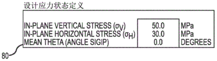
图5(e)是图5(a)所示的应力估计器窗口的设计应力状态定义区域的放大图;Fig. 5(e) is an enlarged view of the design stress state definition area of the stress estimator window shown in Fig. 5(a);
图5(f)是在图5(a)所示的应力估计器窗口的标准应力解决方案区域中描绘的圆形绘图的放大图;Figure 5(f) is an enlarged view of the circular plot depicted in the standard stress solution area of the stress estimator window shown in Figure 5(a);
图5(g)是在图5(a)所示的应力估计器窗口的标准应力解决方案区域中描绘的数据绘图的放大图;Fig. 5(g) is an enlarged view of the data plot depicted in the standard stress solution area of the stress estimator window shown in Fig. 5(a);
图5(h)是在图5(a)所示的应力估计器窗口的2D挖掘应力解决方案区域中描绘的圆形绘图的放大图;Figure 5(h) is an enlarged view of the circular plot depicted in the 2D Dig Stress Solutions area of the stress estimator window shown in Figure 5(a);
图5(i)是在图5(a)所示的应力估计器窗口的2D挖掘应力解决方案区域中描绘的数据绘图的放大图;Figure 5(i) is an enlarged view of the data plot depicted in the 2D Mining Stress Solutions area of the Stress Estimator window shown in Figure 5(a);
图6(a)是岩体特征模块生成的岩体特征窗口的图像表示;Figure 6(a) is an image representation of the rock mass feature window generated by the rock mass feature module;
图6(b)是图6(a)所示的岩体特征窗口的数据输入区域的放大图;Fig. 6(b) is an enlarged view of the data input area of the rock mass feature window shown in Fig. 6(a);
图6(c)是图6(a)所示的岩体特征窗口的岩体质量和岩体评级数据区域的放大图;Fig. 6(c) is an enlarged view of the rock mass quality and rock mass rating data area of the rock mass feature window shown in Fig. 6(a);
图7(a)是各种地面类型分类的图像表示;Figure 7(a) is an image representation of various ground type classifications;
图7(b)是可以基于地质强度指标和压缩强度的比率用于估计地面类型分类的决策算法的图形化表示;Figure 7(b) is a graphical representation of a decision algorithm that can be used to estimate ground type classifications based on the ratio of geological strength indices and compressive strengths;
图8(a)是地面支撑设计图解模块生成的设计图解窗口的图像表示;Figure 8(a) is a graphical representation of the design diagram window generated by the ground support design diagram module;
图8(b)是图8(a)所示的设计图解窗口的数据输入和容量检验区域的放大图;Fig. 8(b) is an enlarged view of the data input and capacity inspection area of the design diagram window shown in Fig. 8(a);
图8(c)是图8(a)所示的设计图解窗口的横截面视图区域的放大图;Fig. 8(c) is an enlarged view of the cross-sectional view area of the design illustration window shown in Fig. 8(a);
图8(d)是图8(a)所示的设计图解窗口的展开视图区域的放大图;Fig. 8(d) is an enlarged view of the expanded view area of the design illustration window shown in Fig. 8(a);
图9(a)是故障深度模块生成的故障深度窗口的图像表示Figure 9(a) is an image representation of the fault depth window generated by the fault depth module
图9(b)是图9(a)所示的故障深度窗口的数据输入区域的放大图;Fig. 9(b) is an enlarged view of the data input area of the fault depth window shown in Fig. 9(a);
图9(c)是图9(a)所示的故障深度窗口的块状岩石评估和大接缝(heavilyjointed)岩石区域的放大图;Fig. 9(c) is an enlarged view of the bulk rock assessment and the heavily joined rock region of the failure depth window shown in Fig. 9(a);
图10(a)是突发(bursting)支撑设计模块生成的突发支撑设计窗口的图像表示;Figure 10(a) is a graphical representation of the bursting support design window generated by the bursting support design module;
图10(b)是图10(a)所示的突发支撑设计窗口的数据输入区域的放大图;Fig. 10(b) is an enlarged view of the data input area of the burst support design window shown in Fig. 10(a);
图10(c)是图10(a)所示的突发支撑设计窗口的参考表的放大图;Fig. 10(c) is an enlarged view of the reference table of the burst support design window shown in Fig. 10(a);
图11(a)是交叉设计模块生成的交叉设计窗口的图像表示;Figure 11(a) is a graphical representation of the cross-design window generated by the cross-design module;
图11(b)是图11(a)所示的交叉设计窗口的交叉示意区域的放大图;Fig. 11(b) is an enlarged view of the cross schematic area of the cross design window shown in Fig. 11(a);
图11(c)是图11(a)所示的交叉设计窗口的岩栓间隔曲线(rock bolt spacinggraph)的放大图;以及Figure 11(c) is an enlarged view of the rock bolt spacinggraph of the crossover design window shown in Figure 11(a); and
图11(d)是图11(a)所示的交叉设计窗口的岩栓长度曲线的放大图。Fig. 11(d) is an enlarged view of the rock bolt length curve of the crossing design window shown in Fig. 11(a).
最佳实施方式best practice
地面支撑设计工具或系统10的一个实施方式在图1和图2中示出并且可以包括可用于开发用于地下挖掘的地面支撑设计的多个工具或模块12。地面支撑设计工具10可以在具有至少一个显示系统16和至少一个用户输入系统18的计算机系统14上实施。在这样实施时,地面支撑设计工具10可以包括集成系统,其中各个工具或模块12可以在显示系统16上显示为一个或多个“标签”(未示出),从而允许用户使用输入系统18而容易访问和/或在设计过程期间在各个工具或模块12之间切换。用户输入系统18还允许用户输入各种数据和设计标准至计算机系统14。之后,此类信息、数据和设计标准可以由地面支撑工具10使用以在开发用于地下挖掘的合适的地面支撑设计中协助用户。此外,各个设计细节、性能和安全参数以及设计迭代可以在设计过程期间在显示系统16上表示和显示,如将在本文更加具体描述的。One embodiment of a ground support design tool or
简要来说,地面支撑设计系统10的工具或模块12可以包括挖掘模块22、应力估计器模块24、岩体特征模块26、地面支撑系统示意模块28和楔评估模块30。此外,地面支撑设计工具10还可以配备有依赖各种因素而使用的多个额外的模块或工具。例如,在一个实施方式中,此类额外的模块或工具可以包括故障深度模块32、突发支撑设计模块34、交叉和交叉设计模块36。交叉设计模块36可以包括设计工具或模块38和40以用于3路交叉和4路交叉。Briefly, the tools or
地面支撑开发工具10还可以配备有多个补偿工具或模块13以提供额外的功能。在本文所显示和描述的特定实施方式中,补偿工具或模块13可以包括地面支撑规范模块42、查找表模块44、应力评估输出模块46、最大IP模块48和最小IP模块50。The ground
现在参考图3和7a,用户可以使用地面支撑设计工具10的各个工具或模块12和/或补偿模块13结合设计过程或方法20来开发用于地下挖掘的地面支撑系统设计或配置。如本文将更具体描述的,地面支撑开发方法或设计过程20提供对地面支撑系统配置的初始选择的引导或协助。方法或设计过程20还提供了用于地面支撑系统对于特定估计的地质条件和地面类型分类52(图7)的适用性的迭代评估的手段。在一个实施方式中,地面类型分类52可以是类型“分类1”、“分类2”、“分类3”和“分类4”。此外,方法20可以用于针对几个不同类型的挖掘故障模式来执行快速经验检查。在一个实施方式中,挖掘故障模式可以包括一般的运动学(结构的)不稳定性模式、易碎/炸裂故障模式、动态(如,突发)故障模式和挤压故障模式。Referring now to Figures 3 and 7a, a user may use the various tools or
现在首先参考图3(a、b),设计过程20可以包括几个设计迭代或过程循环54、56、58、60和62,评估和/或迭代其中提出的地面支撑系统设计或配置以确保其满足给定的挖掘、地质和应力条件的需求。设计过程20依赖于特定地面分类类型52和其他因素来分层。例如,如果地面类型分类52是类型分类1,那么满足对安全的运动学稳定性和静态因素的特定需求的地面支撑系统设计或配置将被视为足够的并且设计过程20完成。然而,如果所提出的初始地面支撑系统设计不满足对安全的运动学稳定性和静态因素的需求,那么过程20将继续进行第二次设计迭代循环56。之后,用户可以调整初始地面支撑系统设计或配置直至(现在迭代的或修改的)地面支撑系统设计满足对安全的运动学稳定性和静态因素的需求。Referring now first to Figures 3(a,b), the
如果地面类型分类52是其他类型中的一种,例如分类2、3或4,那么如在图3(a、b)所描述的,过程20继续在设计迭代58、60和62之后进行,直至用于所提出的地下挖掘设计的地面支撑系统设计或配置满足与各自的设计循环58、60和62相关联的各个标准。一旦地面支撑系统设计满足各个各自标准,那么设计过程20将完成。然而,如果在各个设计迭代54、56、58、60和62期间对地面支撑系统配置进行的改变不能产生满足各个各自标准的地面支撑系统配置,那么过程20返回(如间断线21、23和25所指示的)至初始步骤64,在初始步骤64中用户可以改变地下挖掘的基础配置。之后,设计过程20可以再次继续直至用于新的地下挖掘配置的支撑系统设计满足需求。If the ground type classification 52 is one of the other types, such as
本发明的重大优势在于其提供了单个集成系统或工具10,该单个集成系统或工具10包含开发满足给定的挖掘、地质和应力条件的需求的地面支撑系统设计所需的所有分析工具或模块。此外,输入至各个模块的信息和数据以及由每一个模块执行的计算或运算自动地在各个模块之间传递或传达,从而使开发过程流水线化并且大大降低在开发过程期间不经意地引入错误的可能性。此外,满意的和不满意的地面支撑设计可以立即反映,例如通过地面支撑系统示意工具28。更特别地,开发得不满意的或不好的地面支撑系统设计元件可以用红色在地面支撑示意中指示,从而允许用户改变设计“在飞行中”直至(如通过使用绿色)提供满意的指示。A significant advantage of the present invention is that it provides a single integrated system or
其他优势还与开发过程20相关联。例如,各个设计迭代或循环54、56、58、60和62提供了改进的设计方法,其中仅执行要求满足特定地面类型分类的设计迭代。此外,在针对给定的初始地下挖掘设计不能开发满意的地面支撑设计时,设计方法20对于引导用户改变或修改地下挖掘设计的情况提供了合理化基础。Other advantages are also associated with the
已经简要描述的地面支撑设计工具10和设计过程20的一个实施方式以及它们的一些更有意义的特性和优势,现在将具体描述地面支撑设计工具和设计过程20的各个实施方式和可替代的配置。然而,应当注意的是虽然以下的说明是针对各个实施方式和可替代的结构和方法的,但是地面支撑设计工具10和设计过程20的其他变形和修改对已经熟悉本文所提供的教示之后的本领域普通技术人员来说是显而易见的。因此,本发明不应当被视为限于本文所显示的和所描述的特定结构布置、配置、材料和方法。Having briefly described one embodiment of the ground
现在返回参考图1和图2,地面支撑设计工具10的一个实施方式可以在计算机系统14上实施。计算机系统14可以与显示系统16和用户输入系统18功能性关联。如所提到的,地面支撑设计工具的各个工具或模块12和13可以包括集成系统,其中各个模块12和13可以在显示系统16上显示为多个标签(未示出)。系统用户可以通过使用输入系统18访问各个模块以通过“点击”相应标签来选择合适的模块。显示系统16然后将显示与所选择的模块12和13相关联的合适的域、信息和数据。用户然后可以使用与计算机系统14相关联的显示和输入系统16和18以在设计过程20之后开发适合于特定地下挖掘设计的地面支撑系统设计和配置。Referring now back to FIGS. 1 and 2 , one embodiment of the ground
如之前简要提到的,地面支撑系统开发工具10可以包括多个工具或模块12,多个工具或模块12可以在各个结合中使用以协助用户开发适合于所提到的地下挖掘的地面支撑系统设计或配置。在本文所显示的和所描述的特定实施方式中,地面支撑设计工具10可以包括挖掘细节工具或模块22、应力估计器模块工具24、岩体特征模块或工具26、地面支撑系统示意工具28和楔评估工具30。此外,地面支撑设计工具10还可以配备有依赖各种因素而使用的多个额外的模块或工具。那些额外的模块或工具可以包括故障深度模块或工具32、突发支撑设计模块或工具34和交叉设计工具36。交叉设计工具36可以包括设计工具38和40以用于3路和4路交叉。As briefly mentioned before, the ground support
地面支撑开发工具10还可以配备有多个补偿工具或模块13以提供额外的功能。这些补偿工具或模块13还可以在显示系统16上显示为一个或多个标签(未示出),从而允许用户在设计过程期间容易地访问各个补偿工具或模块13。在本文所示和所描述的特定实施方式中,补偿工具或模块13可以包括地面支撑规范工具42、查找表工具44、应力评估输出工具或模块46、最大IP工具48和最小IP工具50。The ground
现在具体考虑各个工具或模块12和13,挖掘细节模块22可以配置为生成地下挖掘细节窗口66,如图4所显示的。地下挖掘细节窗口66可以包括输入数据域区68和系统标识区70。输入数据域区68允许用户输入与所计划的地下挖掘的大小、形状和方向有关的信息和数据。系统标识区70可以用于提供关于地面支撑设计工具10的版本、评估日期、图号、评估区域和用户的标识的信息。Considering now in detail the various tools or
在本文所示的和所描述的特定实施方式中,输入数据域区68包括用于所计划的地下挖掘的跨度、高度、形状、走向和倾伏(Plunge)的域。输入数据域区68还可以包括用于显示所评估的顶部和墙壁的等价半径的域。所提出的地下挖掘的跨度和高度是所计划的地下挖掘的宽度(即,从墙壁到墙壁)和高度(即,从地板到顶部)。挖掘细节工具22可以配置为基于跨度和高度的输入值来计算或确定地下挖掘的顶部和墙壁的等价半径。也就是说,因为大多数地下挖掘在形状上大概是矩形的(如图8a和8c所显示的),但是大多数经验上的估计假定圆形开口,挖掘细节工具22可以用于基于所提出的地下挖掘的跨度和高度来估计等价圆形开口。在一个实施方式中,挖掘细节工具22根据以下等式来估计地下挖掘的顶部和墙壁的等价半径:In the particular embodiment shown and described herein, the input data field area 68 includes fields for the span, height, shape, strike, and plunge for the planned underground excavation. The input data field area 68 may also include fields for displaying the estimated equivalent radii of the roof and walls. The proposed underground excavation span and height are the width (ie, from wall to wall) and height (ie, from floor to top) of the planned underground excavation. The


开口的形状用于其他模块以计算围绕具有某些本领域已知的定义的形状的地下开口的切应力(tangential stresses)。在图4所示的示例中,地下挖掘的形状是“马蹄”。挖掘的走向是地下挖掘的方向。在一个实施方式中,走向以从矿的北边且范围从1°至360°的角度来测量。倾伏是地下挖掘的下沉或倾斜。向下倾斜为正,而向上倾斜为负。The shape of the opening is used in other modules to calculate tangential stresses around subterranean openings having certain defined shapes known in the art. In the example shown in Figure 4, the shape of the underground excavation is "horseshoe". The direction of the excavation is the direction of the underground excavation. In one embodiment, strike is measured from the north side of the mine at an angle ranging from 1° to 360°. A slump is the subsidence or incline of an underground excavation. A downward slope is positive, while an upward slope is negative.
应力估计器模块24可以与挖掘细节模块22功能性关联,以使得信息和数据可以在两个工具或模块22和24之间交换。应力估计器模块24接受来自用户的与特定应力计算参数有关的输入。应力估计器工具24基于与应力计算参数有关的输入信息以及基于关于待开发的地下挖掘的信息来计算地下挖掘附近的地面应力。The
现在参考图5(a-i),应力估计器工具24可以生成可以在显示系统16上显示的应力估计器窗口72。应力估计器窗口72可以包括适合于接受所需要的输入信息和数据的各个区或区域以及适合于显示与各个应力解决方案有关的信息和数据的各个区或区域。在一个实施方式中,各个数据输入区或区域可以包括应力模型查询坐标区域74、挖掘应力查询区域76、挖掘应力编译器输入区域78和设计应力状态定义区域80。还参见图5(b-e)。Referring now to FIGS. 5( a - i ),
应力模型查询坐标区域74(图5b)允许用户输入与所需要的水平的和垂直的网格间隔和矿坐标有关的信息,该网格间隔即将用作至压力模型数据库查询的输入,而矿坐标对应于感兴趣区域的近似中心。最小和最大矿坐标是基于之前设计的网格间隔和中心坐标的即将输入至应力模型数据库查询的所计算的范围。The stress model query coordinates area 74 (FIG. 5b) allows the user to enter information related to the desired horizontal and vertical grid spacing and mine coordinates to be used as input to the stress model database query, while the mine coordinates Corresponds to the approximate center of the region of interest. The minimum and maximum mine coordinates are the calculated ranges to be entered into the stress model database query based on previously designed grid spacing and center coordinates.
挖掘应力查询区域76(图5c)包括关联挖掘“冲击”和挖掘倾伏的域。这些值从提供给已经描述的挖掘细节模块22的值自动获取。挖掘冲击的值是提供给挖掘细节工具22的挖掘“走向”值。挖掘倾伏的值等于提供给挖掘细节工具22的挖掘倾伏值。迭代域允许用户输入根据三维应力张量(tensor)的特征值和特征向量的即将在标准的(principle)和平面内的应力的计算中使用的迭代的次数。在大多数实施方式中,该值可以默认为10,尽管用户也可以输入其他值。阶段域允许用户输入用于手工应力查询所需要的阶段数。位置域对应于包括在应力模型数据库查询的结果中的位置ID。The excavation stress query region 76 (FIG. 5c) includes a domain that associates excavation "shocks" and excavation dips. These values are automatically obtained from the values provided to the
挖掘应力编译器输入区域78(图5d)允许用户输入用户感兴趣的所编译的数据集的最小和最大百分位值。这些值定义了用于生成图5i中显示的应力量级图的误差线的相对最小值和最大值。该区域78还可以配备有将运行应力编译器宏的运行应力编译器“按钮”。压力编译器宏通过针对来自合适的工程模型的任意范围的所有查询位置的阶段来编译标准的和平面内的压力。应力编译器宏所需要的特定信息和数据可以从挖掘应力编译器输入区域78中的值自动填充。在一个实施方式中,应力编译器宏还可以允许用户输入额外的数据。The mining stress compiler input area 78 (FIG. 5d) allows the user to enter minimum and maximum percentile values for the compiled dataset of interest to the user. These values define the relative minimum and maximum values of the error bars used to generate the stress scale plot shown in Figure 5i. This
设计应力状态定义区域80(图5e)允许用户键入解译结果,该解译结果定义了将用于所有随后的设计评估的平面内应力条件。平面内垂直和水平应力域(Stress fields)接受所估计的平面内垂直和水平应力值(单位为MPa)。Design stress state definition area 80 (FIG. 5e) allows the user to enter interpretation results that define the in-plane stress conditions that will be used for all subsequent design evaluations. The in-plane vertical and horizontal stress fields accept the estimated in-plane vertical and horizontal stress values (in MPa).
如所提到的,应力估计器模块24还可以产生并显示与各个应力解决方案有关的信息和数据。在一个实施方式中,应力估计器模块24可以生成标准应力解决方案区域82和2D挖掘应力解决方案区域84,如最佳在图5a和5f-I中所见。图5f和5g所示的标准应力解决方案区域82可以显示与瞬时和编译的数据二者有关的信息。在标准应力解决方案区域82中提供的制表的和绘制的瞬时标准应力信息对应于在挖掘应力查询区域76中针对阶段和位置输入域的应力张量。制表的值指示每一个标准应力相对于矿坐标系统的量级和方向。然而,在该区域82中,正的倾伏值指示水平以上的角度,而负的值则低于水平。区域82还可以配备有表示标准应力轴与上半球投影(水平对应于圆直径)的交叉位置的立体的或圆形的图。参见图5f。As mentioned, the
在区域82中提供的编译数据图根据查询模型位置的采矿阶段表示了较大的(Sigma 1)、中等的(Sigma 2)和较小的(Sigma 3)标准应力的量级和方向的走向。包括在量级图中的误差线对应于由在应力估计器模块22的挖掘应力编译器输入区域78中键入的最小和最大百分位值定义的范围。线图表示了平均值。走向值是相对于矿坐标系统的。绘制的倾伏数据按照与瞬时值(向上为正)相同的习惯。The compiled data map provided in
现在主要参考图5h和5i,2D挖掘应力解决方案区域84绘制了二维/平面内应力,其垂直地作用于所定义的地下挖掘的顶部/背部、墙壁/侧壁和端壁。当在区域82中提供的标准应力图的条件下,2D挖掘应力解决方案区域84被划分为瞬时的和编译的数据类型。对于瞬时数据类型,制表的值表示了相对于新的挖掘坐标系统的2D平面内(Sigma 1ip和3ip)和平面外(Sigma y'y')应力。所显示的结果对应于在挖掘应力查询区域76(图5c)中定义的阶段和位置的应力张量。Referring now primarily to Figures 5h and 5i, the 2D excavation
Sigma 1ip和Sigma 3ip分别表示在新的x'-z'平面中起作用的平面内最大和最小应力。该平面垂直于挖掘走向而定向,以使得x'轴是水平的并垂直于地下挖掘墙壁/侧壁而z'轴是垂直的和垂直于地下挖掘顶部/背部。值标签还提供平面内应力接近水平的(x'x')和接近垂直(z'z')的一些指示。y'轴平行于挖掘走向并表示平面外应力的方向或者对地下挖掘端壁起作用的方向。Sigma 1ip and Sigma 3ip represent the in-plane maximum and minimum stresses, respectively, acting in the new x'-z' plane. The plane is oriented perpendicular to the excavation trend such that the x' axis is horizontal and perpendicular to the underground excavation walls/sidewalls and the z' axis is vertical and perpendicular to the underground excavation top/back. The value labels also provide some indication that the in-plane stress is near horizontal (x'x') and near vertical (z'z'). The y' axis is parallel to the excavation strike and represents the direction of out-of-plane stress or acting on the end wall of the subterranean excavation.
好像沿着挖掘(y'轴)方向看,图的瞬时数据部分表示平面内应力的方向。图因而提供了相对于挖掘顶部/背部和墙壁/侧壁而分解的平面内应力的方向的指示以协助解释应力条件。The instantaneous data portion of the graph represents the direction of in-plane stress as if looking along the excavation (y' axis) direction. The figure thus provides an indication of the direction of the resolved in-plane stresses relative to the excavation top/back and walls/side walls to assist in the interpretation of the stress conditions.
对于编译的数据类型,区域84可以包括地下挖掘应力量级的图。该图根据采矿阶段表示平面内和平面外应力的截断范围(在最小和最大百分位之间)的平均值。误差线表示由在挖掘应力编译器输入区域78(图5d)中键入的最小和最大百分位值定义的有意义的值的范围。For compiled data types,
区域84还可以包括地下挖掘应力比率和方向的图。该图包括基于平面内和平面外应力的截断平均值通过采矿阶段所计算的平面内和平面外K0值。K0定义为水平应力与垂直应力的比率。并且绘图是在水平以上的Sigma 1ip的角度方向的截断平均值theta(θ)。类似于绘制的应力量级,该值表示在最小和最大百分位值之间的范围的值的平均值。在这些所绘制的值中的走向提供了平面内和平面外应力的方向怎样通过相对于地下挖掘表面的采矿顺序来改变的一些指示。最后,区域84还可以包括通过阶段的Sigma 1ip和Sigma 3ip的图。这些图提供了分解的平面内应力的分布的更具体表示。它们作为标识在挖掘应力量级图中绘制的走向并当解释局部应力条件时使从异常值中产生偏差的可能性最小化的方法而包括。
岩体特征模块26可以生成多个输入域以允许用户输入与正在开发的特定地下挖掘的岩石特征有关的信息。在一个实施方式中,用于计算岩体质量(quality)的各个输入可以基于岩体评级系统和“Q”评级系统,该岩体评级系统是Z.T.、Bieniawski开发的,其发表在Engineering Rock Mass Classifications,Bieniawski,Z.T.,John Wiley&Sons(1989),在下文中称为“RMR89”,而该“Q”评级系统是Norwegian Geotechnical Institute开发的,公开在名称为“Using the Q-System,Rock Mass Classification and SupportDesign”,Oslo,2013,在下文中称为“NGI”。地质强度指数(GSI)的估计对于岩体特征模块26来说也是必要的,其可以从“Predicting Tunnel Squeezing Problems in WeakHeterogenous Rock Masses”,Hoek,E.,和Marinos,P.,Tunnels and Tunneling International 32,no.11,pp.45-51(2000)中获得,在下文中称为“Marinos和Hoek”。在该标签中填入的输入域有助于定义岩体的地质特性以及最终地下挖掘将怎样响应于在原位和采矿减少的应力来表现。在本文所显示的和所描述的特定实施方式中,岩体特征模块26基于与地质特征有关的输入信息估计地面类型分类52(图7a和7b)。如本文进一步具体解释的,所估计的地面类型分类52通过方法20(图3(a、b))在开发用于所提出的地下挖掘的地面系统支撑设计中使用。The rock
现在参考图6(a-c),岩体特征模块26可以生成可以在显示系统16上显示的岩体特征窗口86。岩体特征窗口86可以包括适合于接受所要求的输入信息和数据的各个区或区域以及适合于显示与各个岩体特征有关的信息和数据的各个区或区域。在一个实施方式中,各个数据输入区或区域可以包括数据输入区域88、岩体质量数据区域90和岩体评级数据区域92。Referring now to FIGS. 6( a-c ), the rock
现在参考图6b,数据输入区域88可以包括用户可以输入对应的数据的多个输入域。第一输入域是允许用户键入特征GSI值的估计的地质强度指数(GSI)。数据输入区域88还可以包括用户可以基于所定义的地质状况从下拉列表选择合适的地面类型分类的地面类型分类域。虽然在数据输入区域88的底部的类似域提供了地面支撑分类的估计,用户可以用估计手工定义所要求的分类作为引导。数据输入区域88还可以包括输入域,来允许用户输入域岩体特征(包括岩石密度、岩石质量指标(RQD)、接缝集合的数量、接缝粗糙度、接缝变更、接缝保存、裂缝频率、地面水、强度降低因子(SRF)、挖掘支撑比率、单轴压缩强度和接缝间隔)有关的信息和数据。在数据输入区域88中的保留域通过岩体特征模块26使用本领域已知的信息和计算方法来计算。Referring now to Figure 6b, the
岩体质量数据区域90和岩体评级数据区域92最佳在图6c中可以看到,包含对开发地面支撑系统设计或配置的第一次迭代有用的信息和数据。更特别地,如以上所注意的,岩体质量数据区域90包括来自NGI的图形形式的信息和数据。岩体评级区域还包含与Bieniawski(即,RMR89)的岩体评级系统有关的图形形式的信息和数据。The rock mass
如更早提出的,岩体特征模块26还可以用于估计地面类型分类52。现在参考图7,在一个实施方式中,地面分类类型52可以是类型分类1、分类2、分类3或分类4。该估计根据在图7b中所提供的度量基于所计算的RMR89值(图6b)、完整强度和所估计的平面内应力。平面内应力值采用在应力估计器模块24的设计应力状态区域80(图5e)中键入的设计平面内垂直和水平应力的最大值。As mentioned earlier, the rock
地面支撑设计示意工具或模块28从挖掘细节工具22接收信息和数据并使计算机系统14向用户显示(如,在显示系统16上)待开发的地下挖掘的至少一个示意表示。用户一般将在方法20的迭代设计过程期间广泛使用地面支撑设计示意模块28。楔评估模块30还可以用于提供待开发的地下挖掘的运动学稳定性的评估。The ground support design schematic tool or
地面支撑设计示意模块28可以被配置为生成设计示意窗口96,如在图8a中最佳看到的。设计示意窗口可以包括数据输入和容量检查区域98、横截面视图区域100和展开的视图区域102。应当注意的是有地面支撑设计示意模块28执行的许多计算受到在地面支撑规范模块42中输入的值的直接影响,如将在以下进一步具体讨论的。The ground support design
现在参考图8(b-d),数据输入和容量检查区域98的数据输入区可以配备有允许用户输入与挖掘尺寸(包括挖掘细节模块22所提出的地下挖掘的跨度和高度以及隧道拱半径)有关的信息和数据的输入域。还可以提供与表面支撑有关的信息和数据。在一个实施方式中,与表面支撑有关的细节可以提供用于三层、指定层1、2和3。在输入域中选择的值将在计算和横截面视图区域100中反映。Referring now to Figures 8(b-d), the data entry area of the data entry and
用户还可以输入与螺栓连接系统有关的信息和数据,可能包括两个不同的螺栓连接设计,本文指定为螺栓连接设计1和2。还参见图8d。螺栓连接设计1可以包括用于标识螺栓类型、至第一螺栓的距离(即,从地板至在地下挖掘的侧壁的第一螺栓的距离)、螺栓的数量和螺栓长度的域。螺栓连接设计2可以包括特定用于螺栓连接设计1的域加上额外的域。第一额外的域可以是螺栓安装位置。在一个实施方式中,用户从包括仅背部、仅侧壁或背部和侧壁二者的下拉列表中选择所需要的位置已进行辅助螺栓连接的安装。第二额外的域可以是环形间隔补偿。环形间隔补偿是关于螺栓连接设计1。如果键入零值,螺栓连接设计2的第一环形螺栓将用螺栓设计1的第一环形螺栓线性安装。如果键入大于零的值,则螺栓连接设计2的第一环形根据从螺栓连接设计1通过特定值进行第一环形补偿。The user may also enter information and data related to the bolting system, possibly including two different bolting designs, designated herein as
在一个实施方式中,输入至用于各个螺栓设计配置的数据可以在横截面视图区域100和展开的视图区域102中立即反映,如最佳在图8(c-d)中所见。如果需要的话,不同的颜色可以用于指定各个表面支撑等级和螺栓布置,从而允许用户容易在视觉上分辨正在评估的特定系统支撑设计或配置。In one embodiment, the data entered for each bolt design configuration can be reflected immediately in the
现在返回参考图8(b),数据输入和容量检查区域98的地面支撑容量检查域为静态和动态容量检查提供所计算的数据如下:Referring now back to Figure 8(b), the Ground Support Capacity Check field of the data entry and
安全的设计因子:Safe Design Factors:
该值基于所定义的地下挖掘使用分类使用以下标准表示安全的最小设计因子(FS):This value represents a safe minimum design factor (FS) using the following criteria based on the defined underground excavation usage classification:

一般情况:generally:
可用支撑压强(无喷浆): Available support pressure (no shotcrete) :
这是针对地面支撑系统所估计的支撑压强。假定喷浆没有提供任何有效的表面压强,并假定即将是结合元件。This is the estimated support pressure for the ground support system. It is assumed that the shotcrete does not provide any effective surface pressure and that the bonding element is imminent.
可用支撑压强(伸缩的(scaled)): Available support pressure (scaled) :
这是基于采用地下挖掘的1/3跨度的顶点高度的楔的伸缩的支撑压强。术语伸缩意味着螺栓的“真实”容量是在楔的顶点高度以上的长度可用的。This is based on the telescoping support pressure using wedges of 1/3 span apex height excavated underground. The term telescoping means that the "true" capacity of the bolt is available in length above the height of the apex of the wedge.
位移:Displacement:
可用位移容量: Available displacement capacity :
这是支撑系统的最大位移值。所计算的值在其与最大需要位移之间的比率大于或等于以上定义的可用设计FS的情况下将以绿色呈现。所计算的值在FS小于设计标准的情况下将以红色呈现。This is the maximum displacement value of the support system. The calculated value will be rendered in green if its ratio to the maximum required displacement is greater than or equal to the available design FS defined above. The calculated value will be presented in red where the FS is less than the design criteria.
要求的位移顶部/背部: Required displacement top/back :
这是根据故障深度模块32的计算采用的顶部/背部的所估计的位移/聚合。其根据大量且严重的接缝岩体情况表现了巨大的(即,最大的)估计位移值。This is the estimated displacement/aggregation of the top/back taken from the calculation of the
要求的位移侧壁: Required displacement sidewall :
这是根据故障深度模块32的计算采用的侧壁的计算位移/聚合。其根据大量且严重的接缝岩体情况表现了巨大的(即,最大的)估计位移值。This is the calculated displacement/aggregation of the sidewalls taken from the calculations of the
静态容量:Static capacity:
可用顶部/背部楔容量(伸缩的): Available top/back wedge capacities (retractable) :
这是用于地下挖掘顶部/背部的总的伸缩支撑容量。该值基于伸缩的螺栓容量(即,从楔以上的长度的容量)和指定的螺栓间隔来计算。This is the total telescopic support capacity for the top/back of the underground excavation. This value is calculated based on the telescoping bolt capacity (ie, the capacity from the length above the wedge) and the specified bolt spacing.
要求的顶部/背部楔支撑容量: Required top/back wedge support capacity :
这是理论上四面体的楔所要求的支撑容量,顶点高度是地下挖掘的跨度的1/3。This is the required support capacity for a wedge of a theoretical tetrahedron, with the apex height being 1/3 the span of the underground excavation.
顶部/背部楔安全系数: Top/Back Wedge Safety Factor :
计算为可用的、伸缩的容量与要求的支撑容量的比率。所计算的值在其大于或等于以上所计算的FS设计标准的情况下将在显示器上以绿色呈现。所计算的值在其小于设计FS的情况下将以红色呈现。Calculated as the ratio of available, retractable capacity to required support capacity. The calculated value will appear in green on the display if it is greater than or equal to the FS design criteria calculated above. The calculated value will be rendered in red if it is less than the design FS.
可用顶部/背部故障深度容量(伸缩的): Available top/back failure depth capacity (retractable) :
这是伸缩基于来自故障深度模块32的易碎/爆裂故障的最大深度而计算的在地下挖掘顶部/背部的支撑系统(不包括喷浆或网眼)的静态容量。为了使螺栓具有其最大容量,必须具有足够的嵌入件来进行。具有小于炸裂深度的长度的螺栓将具有容量为零。This is the static capacity of the support system (not including shotcrete or mesh) at the top/back of the subterranean excavation calculated based on the maximum depth of frangible/bursting faults from the
要求的顶部/背部故障深度容量: Required Top/Back Failure Depth Capacity :
这是从来自故障深度模块32的易碎/炸裂故障的最大深度计算的和来自岩体特征模块26的岩石密度定义的顶部/背部所要求的静态容量。This is the top/back required static capacity calculated from the maximum depth of the frangible/explosive fault from the
静态顶部/背部安全系数: Static top/back safety factor :
计算为故障容量的可用顶部/背部深度与故障容量的要求深度的比率。所计算的值在其大于或等于以上所计算的FS设计标准的情况下将在显示器上以绿色呈现。所计算的值在其小于设计FS的情况下将以红色呈现。Calculated as the ratio of the available top/back depth for failure capacity to the required depth for failure capacity. The calculated value will appear in green on the display if it is greater than or equal to the FS design criteria calculated above. The calculated value will be rendered in red if it is less than the design FS.
可用侧壁故障深度容量(伸缩的): Available Sidewall Failure Depth Capacity (Scalable) :
这是伸缩基于来自故障深度模块32的易碎/炸裂故障的最大深度而计算的在地下挖掘侧壁的支撑系统(不包括喷浆或网眼)的静态容量。为了使螺栓具有其最大容量,必须具有足够的嵌入件来进行。具有小于炸裂深度的长度的螺栓将视为具有容量为零。This is the static capacity of the support system (not including shotcrete or mesh) for excavating sidewalls underground as calculated by the telescoping based on the maximum depth of frangible/explosive faults from the
要求的侧壁故障深度容量: Required Sidewall Failure Depth Capacity :
这是从来自故障深度模块32的易碎/炸裂故障的最大深度计算的和来自岩体特征模块26的岩石密度定义的侧壁所要求的静态容量。This is the required static capacity of the sidewall calculated from the maximum depth of the frangible/explosive fault from the
静态侧壁安全系数: Static side wall safety factor :
计算为故障容量的可用侧壁深度与故障容量的要求深度的比率。所计算的值在其大于或等于以上所计算的FS设计标准的情况下将在显示器上以绿色呈现。所计算的值在其小于设计FS的情况下将以红色呈现。Calculated as the ratio of the available sidewall depth for failure capacity to the required depth for failure capacity. The calculated value will appear in green on the display if it is greater than or equal to the FS design criteria calculated above. The calculated value will be rendered in red if it is less than the design FS.
动态容量Dynamic capacity
应当注意的是在大多数实施方式中在从动态容量所呈现的值得到的输入无论如何是主观的。因此,动态容量值在大多数情况下将主要用于引导。It should be noted that in most embodiments the input derived from the value presented by the dynamic capacity is subjective anyway. Therefore, the dynamic capacity value will be used primarily for bootstrapping in most cases.
可用能量容量侧壁/墙壁(伸缩的): Available Energy Capacity Sidewall/Wall (Telescopic) :
这是墙壁/侧壁支撑系统的所计算的能量容量。伸缩的指定意味着支撑容量基于炸裂损伤的最大深度是伸缩的。因此,为了使螺栓具有其最大容量,必须具有足够的嵌入件来进行。具有小于炸裂深度的长度的螺栓将视为零容量。值以千焦(KJ)为单位并且从故障深度模块32得到。This is the calculated energy capacity of the wall/sidewall support system. The designation of telescoping means that the support capacity is telescopic based on the maximum depth of blast damage. Therefore, in order for the bolt to have its maximum capacity, there must be enough inserts to do so. Bolts with a length less than the burst depth will be considered zero capacity. Values are in kilojoules (KJ) and are derived from
可用能量容量侧壁: Available Energy Capacity Sidewalls :
这是从故障深度模块32直接得到的侧壁中的事件要求的估计的能量容量。This is the estimated energy capacity required by events in the sidewall directly from the
动态顶部/背部安全系数: Dynamic top/back safety factor :
计算为可用能量容量顶部/背部与所要求的能量顶部/背部容量的比率。所计算的值在其大于或等于以上所计算的FS设计标准的情况下将在显示器上以绿色呈现。所计算的值在其小于设计FS的情况下将在显示器上以红色呈现。Calculated as the ratio of the available energy capacity top/back to the required energy top/back capacity. The calculated value will appear in green on the display if it is greater than or equal to the FS design criteria calculated above. The calculated value will be rendered in red on the display if it is less than the design FS.
要求的能量容量顶部/背部(伸缩的): Required energy capacity top/back (retractable) :
这是墙壁/侧壁支撑系统的所计算的能量容量。伸缩的指定意味着支撑容量基于炸裂的最大深度是伸缩的。为了使螺栓具有其最大容量,必须具有足够的嵌入件来进行。具有小于炸裂深度的长度的螺栓将具有零容量。值以KJ为单位并且从故障深度模块32得到。This is the calculated energy capacity of the wall/sidewall support system. The designation of telescoping means that the support capacity is telescopic based on the maximum depth of the burst. In order for the bolt to have its maximum capacity, there must be enough inserts to do so. Bolts with a length less than the burst depth will have zero capacity. The value is in KJ and obtained from the
要求的能量容量顶部/背部: Required Energy Capacity Top/Back :
这是从故障深度模块32直接得到的顶部/背部中的事件要求的估计的能量容量。This is the estimated energy capacity required for events in the top/back directly from the
动态侧壁安全系数: Dynamic Sidewall Safety Factor :
计算为可用能量容量顶部/背部侧壁与所要求的能量侧壁容量的比率。所计算的值在其大于或等于以上所计算的FS设计标准的情况下将在显示器上以绿色呈现。所计算的值在其小于设计FS的情况下将以红色呈现。Calculated as the ratio of the available energy capacity top/back sidewall to the required energy sidewall capacity. The calculated value will appear in green on the display if it is greater than or equal to the FS design criteria calculated above. The calculated value will be rendered in red if it is less than the design FS.
如之前简要提到的,地面支撑设计工具10还可以配备有依赖各种因素而使用的并且功能需要的多个额外的模块或工具。在本文所显示的和所描述的特定实施方式中,此类额外的模块或工具可以包括故障深度模块或工具32。故障深度模块32可以用于岩石的地质特征使特定故障模式更可能的特定情况。例如,在本文所显示的和所描述的特定实施方式中,故障深度模块32在所估计的地面类型分类为除了类型1的情况下使用,如,可以通过岩体特征模块26来确定。故障深度工具32生成多个输入域来允许用户输入特定信息,包括炸裂开始阈值。故障深度模块32还可以接收或使用来自岩体特征模块26的特定信息和数据。故障深度模块32然后可以将该信息和数据用于确定故障深度,以用于给定集合的岩体属性和应力。由故障深度模块32执行的计算还可以分析大量且严重的接缝岩体。As briefly mentioned before, the ground
现在参考图9,故障深度模块32的一个实施方式可以被配置为生成(如,在图1的显示系统16上)故障深度窗口106。故障深度窗口106可以包括输入数据域区域108、块状岩评估区域110和严重接缝的岩石区域112。Referring now to FIG. 9 , one embodiment of
在本文所显示的和所描述的特定实施方式中,输入数据域区域108包括用于输入域炸裂初始阈值有关的数据的域。炸裂初始阈值是在开始炸裂时最大减小应力与σmax完整的单轴压缩强度σci的比率。较高阈值意味着损伤将在较高应力等级减小。该值在计算炸裂故障深度中使用,根据以下公开的技术:“Measurement of Spalling Parameters fromLaboratory Testing”,Diederichs、M.S.和Martin,C.D.,Rock Mechanics and Environmental Engineering,pp.323-326,(2010),在下文中为“Diederichs和Martin”。两个其他数据输入域用于键入材料常数(mi)以用于完整的岩石和干扰因素(D),如在以下所公布的:“Underground Excavations In Rock”,Hoek,E.和Brown,E.T.,Instn.Min.Metal,London,1980在下文中为“Hoek和Brown”。材料常数值在计算岩体材料常数mb中使用。干扰因素的范围为0-1并且表示由于挖掘过程本身减小至地下挖掘的损伤量。该是在计算故障深度和严重接缝岩体的预期张力时使用。In the particular embodiment shown and described herein, the input
输入数据域区域108中的剩余域包括从应力估计器模块24和岩体特征模块26自动输入的数据,如以上所描述的。The remaining fields in the input data fields
故障深度模块32还包括经验上减小的应力估计和经验上岩体应力估计的域,如在输入数据域区域108中所描述的。各个经验上的估计通过故障深度模块32确定如下:The
经验上减小的应力估计:Empirically reduced stress estimates:
对于该部分内的所有项,以下变量定义如下:For all items within this section, the following variables are defined as follows:
σmax=最大切线应力(MPa)σ max = maximum tangential stress (MPa)
σv=平面内垂直应力(MPa)σ v = In-plane vertical stress (MPa)
σh=平面内水平应力(MPa)σ h = horizontal stress in plane (MPa)
σci=完整的压缩强度(MPa)σ ci = full compressive strength (MPa)
K0 : K 0 :
这是水平应力与垂直应力的比率。小于1的K0值指示垂直应力是占优势的而大于1的K0值指示水平应力是占优势的。K0值根据在应力估计器模块24中键入的应力值来计算。This is the ratio of horizontal stress to vertical stress. A value of K 0 less than 1 indicates that vertical stress is dominant and a value of K 0 greater than 1 indicates that horizontal stress is dominant. The K 0 value is calculated from the stress values entered in the
Kirsch解决方案-墙壁: Kirsch Solutions - Walls :
这是基于K0比率的地下挖掘的墙壁中的最大切线应力、在应力估计器模块24中键入的垂直应力和围绕理想化的、圆形地下挖掘的相对于水平的旋转角度θ:This is the maximum tangential stress in the wall of the underground excavation based on the K0 ratio, the vertical stress entered in the
σmax-wall=σv[(1+K0)+2(1-K0)cos2θ] (3)σ max-wall =σ v [(1+K 0 )+2(1-K 0 )cos2θ] (3)
其中θ=0度。where θ = 0 degrees.
Kirsch解决方案-顶部/地板: Kirsch Solution - Top/Floor :
这是基于K0比率的地下挖掘的墙壁中的最大切线应力、在应力估计器模块24中键入的垂直应力和围绕理想化的、圆形地下挖掘的相对于水平的旋转角度θ:This is the maximum tangential stress in the wall of the underground excavation based on the K0 ratio, the vertical stress entered in the
σmax-roof=σv[(1+K0)+2(1-K0)cos2θ] (4)σ max-roof =σ v [(1+K 0 )+2(1-K 0 )cos2θ] (4)
其中θ=90度。where θ = 90 degrees.
比率σmax/σci-墙壁: Ratio σ max /σ ci - wall :
这是在地下挖掘的墙壁中开发的最大切线应力(用MPa测量)除以σci的比率。该比率用于评估块状岩中的炸裂深度。This is the ratio of the maximum tangential stress (measured in MPa) developed in an underground excavated wall divided by σci . This ratio is used to assess fracturing depth in massive rocks.

比率σmax/σci–顶部/地板: Ratio σ max /σ ci – top/floor :
这是在地下挖掘的背部中开发的最大切线应力(用MPa测量)除以σci的比率。该比率用于评估块状岩中的炸裂深度。This is the ratio of the maximum tangential stress (measured in MPa) developed in the back of an underground excavation divided by σci . This ratio is used to assess fracturing depth in massive rocks.
切线应力顶部(σθr): Tangent stress top (σ θr ) :
该值是基于地下挖掘的形状的预期最大切线顶部应力(MPa)。值由在岩体特征模块26中选择的地下挖掘的形状确定。值基于在Hoek和Brown中提供的关系来计算。This value is the expected maximum tangential top stress (MPa) based on the shape of the underground excavation. The value is determined by the shape of the underground excavation selected in the rock
切线应力墙壁(σθw): Tangent Stress Wall (σ θw ) :
该值是基于地下挖掘的形状的预期最大切线墙壁应力(MPa)。值由在岩体特征模块26中选择的地下挖掘的形状确定。值基于在Hoek和Brown中提供的关系来计算。This value is the expected maximum tangential wall stress (MPa) based on the shape of the underground excavation. The value is determined by the shape of the underground excavation selected in the rock
经验上的岩体强度估计:Empirical estimation of rock mass strength:
地质强度指数,GSI: Geological Strength Index, GSI :
值从在岩体特征模块26的估计值输入得到。值用作值Hoek和Brown岩体强度计算的输入。The value is derived from the estimated value input in the rock
Hoek Brown(mb): Hoek Brown(m b ) :
这是岩体的降级的mi材料常数,如公布于“Hoek-Brown Failure Criterion-2002Edition”,Hoek,E.等,Proceedings of NARMS-Tac,pp.267-273,(2002)在下文中为“Hoek等”。该值在计算故障深度和严重接缝岩体的期望应变中使用。值基于SGI值来计算。This is the degraded mi material constant of the rock mass, as published in "Hoek-Brown Failure Criterion-2002 Edition", Hoek, E. et al., Proceedings of NARMS-Tac , pp. 267-273, (2002) hereinafter "Hoek"Wait". This value is used in calculating failure depths and expected strains for severely jointed rock masses. The value is calculated based on the SGI value.
Hoek Brown(s): Hoek Brown(s) :
岩体的材料常数,根据Hoek等。该值在计算故障深度和严重接缝岩体的期望应变中使用。值基于SGI值来计算。Material constants of rock masses, according to Hoek et al. This value is used in calculating failure depths and expected strains for severely jointed rock masses. The value is calculated based on the SGI value.
Hoek Brown(a): Hoek Brown(a) :
岩体的材料常数,根据Hoek等。该值在计算故障深度和严重接缝岩体的期望应变中使用。值基于SGI值来计算。Material constants of rock masses, according to Hoek et al. This value is used in calculating failure depths and expected strains for severely jointed rock masses. The value is calculated based on the SGI value.
岩体强度(σcm): Rock mass strength (σ cm ) :
这是根据在Hoek等中定义的等式计算的岩体强度。This is the rock mass strength calculated according to the equation defined in Hoek et al.

块状岩评估区域110包括针对墙壁/侧壁和顶部/背部二者采用相同经验等式和不同的挖掘减小的应力输入的计算域;墙壁/侧壁计算参考“Kirsch解决方案-墙壁”值而顶部/背部计算参考“Kirsch解决方案-顶部/地板”值。该区域110中计算域的概要在下面提供。Massive
在继续进行之前应当注意的是故障深度的所有计算表示了没有支撑安装情况下状况。支撑的应用提供了限制、抑制了炸裂并用作减小故障深度。由此,这些估计是固有保守的。Before proceeding it should be noted that all calculations for depth of failure represent conditions without support. The application of bracing provides restraint, suppresses bursting and serves to reduce the depth of failure. As such, these estimates are inherently conservative.
炸裂深度-(比率σmax/σci): Burst depth - (ratio σ max /σ ci ) :
这是地下挖掘的墙壁/侧壁或顶部/背部的σmax/σci的比率。值基于σci和各自Kirsch解决方案来计算。This is the ratio of σ max /σ ci for walls/side walls or top/back excavated underground. Values are calculated based on σ ci and the respective Kirsch solutions.
炸裂故障深度: Burst failure depth :
这是基于在Diederichs和Martin中提供的等式的计算的故障深度。在确定炸裂开始处于怎样的σmax/σci比率的炸裂参数可以被调整为更好地对应现场观察。炸裂参数一般在0.4-0.5的范围。This is the calculated failure depth based on the equation provided in Diederichs and Martin. The burst parameters in determining at what σ max /σ ci ratio the burst begins can be adjusted to better correspond to field observations. The burst parameters are generally in the range of 0.4-0.5.
膨胀位移(膨胀5%): Expansion displacement (
该值是在地下挖掘的侧壁上的期望位移。将值乘以2而计算结束。计算假定安装了硬的地面支撑,其使预期扩大/膨胀减小5%。This value is the desired displacement on the sidewall of the underground excavation. Multiply the value by 2 and the calculation ends. Calculations assume the installation of hard ground supports that reduce expected expansion/expansion by 5%.
严重接缝岩石区域112还对墙壁/侧壁和顶部/背部二者采用相同的经验等式,但是挖掘减小应力输入基于各自的计算而改变。墙壁/侧壁解决方案利用“平面内应力(垂直)σv”和“Kirsch解决方案-墙壁”值,而顶部/背部计算使用“平面内应力(水平)σH”和“Kirsch解决方案-顶部/地板”值。以下提供了在标签的该部分的计算域的概要。The heavily jointed
静态故障深度Static fault depth
故障深度静态(以米为单位): Fault Depth Static (in meters) :
该值是在静态状况下严重接缝或类似土壤的岩体的故障预期深度。值基于由Hoek和Marinos表示的等式来计算。This value is the expected depth of failure for heavily seamed or soil-like rock masses in static conditions. Values are calculated based on the equation expressed by Hoek and Marinos.

其中:in:
dp=塑料区半径;d p = radius of plastic zone;
do=以米为单位的原隧道半径;d o = original tunnel radius in meters;
pi=内部支撑压强 pi = internal support pressure
p0=原位应力=深度×岩体单位重量;以及
岩体强度基于Hoek等来确定。用于计算的内部支撑应力值来自地面支撑系统示意模块28。在顶部/背部计算的情况下,所使用的支撑应力是伸缩值,意味着支撑容量限于嵌入在最大的理论的楔块(参见地面支撑系统示意模块28中“估计的可用支撑应力(伸缩的)”域说明)之外的一部分钢筋提供的容量。The rock mass strength was determined based on Hoek et al. The internal support stress values used for the calculation come from the ground support system
隧道挤压图表(%闭合张力): Tunnel Extrusion Chart (% Closing Tension) :
这是使用以下关系估计的%闭合张力值,其显示在“Estimation of TunnelSqueezing in Anisotropic Stress Fields using a FLAC-Based Neural Network”,Continuum and Distinct Element Numerical Modeling in Geomechanics-2011,(2011),下文中为“DeGagne等”:This is the estimated % closed tension value using the following relationship, which is shown in "Estimation of TunnelSqueezing in Anisotropic Stress Fields using a FLAC-Based Neural Network", Continuum and Distinct Element Numerical Modeling in Geomechanics-2011 , (2011), below "DeGagne et al":

其中in
σcm是岩体强度;以及σ cm is the rock mass strength; and
σmax是来自Kirsch解决方案的各自的最大(墙壁或顶部)应力。σ max is the respective maximum (wall or top) stress from the Kirsch solution.
隧道挤压图表(闭合): Tunnel extrusion diagram (closed) :
该计算基于各自的原始地下挖掘尺寸(跨度或高度)将所估计的%闭合应变值转换为闭合尺寸。This calculation converts the estimated % closed strain values to closed dimensions based on the respective original underground excavation dimensions (span or height).
另一个模块可以包括突发支撑设计模块或工具34。突发支撑设计工具34可以生成多个输入域以允许用户输入(如,经由计算机系统14)与膨胀因子、正在评估的膨胀事件的喷射速度和所提出的地板支撑系统的能量容量有关的信息。突发支撑设计工具然后通过快速膨胀确定或估计施加在地板支撑系统上的要求。主要计算假定占优势的损伤机制是由于从应变突发事件产生的喷射而膨胀。如果需要的话,突发支撑设计工具34还可以由于通过远程地震事件触发的突发事件产生损伤估计,即使这种功能不是必要的。Another module may include a burst support design module or
在一个实施方式中,突发支撑设计模块34生成或产生具有数据输入区域116的突发支撑设计窗口114,如最佳在图10(a-c)中所见。突发支撑设计窗口114还可以配备有一个或多个参考表格118和120,其可以显示提供给用户关于各个方面的引导,包括损伤严重性评级等级、岩石突发损伤机制和期望损伤的性质。In one embodiment, the burst
数据输入区域116提供用于输入的域和用于故障模式评估的计算数据如下:The
膨胀评估:Bloat assessment:
膨胀因子(%): Expansion Factor (%) :
用户键入在随后膨胀计算中即将使用的所需要的膨胀因子。这允许用户回顾支撑系统上膨胀因子的作用。以下值是基于支撑类型推荐的:The user enters the desired inflation factor to be used in subsequent inflation calculations. This allows the user to review the effect of the expansion factor on the support system. The following values are recommended based on support type:
无螺栓连接-30%Boltless - 30%
轻螺栓连接-7-13%Light Bolting - 7-13%
柔韧支撑-4-6%Flexible Support - 4-6%
硬支撑-1.0-2.0%Hard Support -1.0-2.0%
膨胀位移顶部: Expansion Displacement Top :
该值是通过所定义的膨胀因子和由用于地下挖掘顶部的故障深度模块32计算的最大故障深度得到的位移。This value is the displacement resulting from the defined expansion factor and the maximum fault depth calculated by the
膨胀位移侧壁: Expansion Displacement Sidewall :
该值是通过所定义的膨胀因子和由用于地下挖掘侧壁的故障深度模块32计算的最大故障深度得到的位移。This value is the displacement resulting from the defined expansion factor and the maximum failure depth calculated by the
膨胀位移地板: Expansion displacement floor :
该值是通过所定义的膨胀因子和由用于地下挖掘地板的故障深度模块32计算的最大故障深度得到的位移。在一个实施方式中,假定等于顶部/背部故障深度。This value is the displacement resulting from the defined expansion factor and the maximum fault depth calculated by the
喷射评估:Jet Evaluation:
重力: Gravity :
这是由于重力的加速度。缺省值是9.81m/s2。This is due to the acceleration of gravity. The default value is 9.81m/s 2 .
喷射质量(顶部/地板): Jet Quality (Top/Floor) :
这是可能在动态事件期间喷射的预期岩石质量。该质量根据故障深度模块32计算的故障深度来估计。This is the expected rock mass that might be ejected during a dynamic event. The quality is estimated from the fault depth calculated by the
喷射重量(顶部/地板): Jet Weight (Top/Floor) :
这是可能在动态事件期间喷射的预期岩石重量。该重量根据故障深度模块32计算的故障深度来估计。This is the expected rock weight that might be ejected during a dynamic event. The weight is estimated from the depth of failure calculated by the depth of
喷射质量(墙壁/侧壁): Jet Quality (Wall/Sidewall) :
这是可能在动态事件期间喷射的预期岩石质量。该质量根据故障深度模块32计算的故障深度来估计。This is the expected rock mass that might be ejected during a dynamic event. The quality is estimated from the fault depth calculated by the
喷射重量(墙壁/侧壁): Spray Weight (Wall/Sidewall) :
这是可能在动态事件期间喷射的预期岩石重量。重量根据故障深度模块32计算的故障深度来估计。This is the expected rock weight that might be ejected during a dynamic event. The weight is estimated from the fault depth calculated by the
喷射速度(Ve): Injection velocity (V e ) :
这是正在评价的膨胀事件的喷射速度。根据其他矿体的经验已经显示速度范围一般在1-3米每秒(m/s)。非常困难的是预知喷射是否将出现,但是一些一般的经验规则可以用于评估地下的在先应变突发事件。如果材料被喷射并且位移超过其休止角,喷射速度必须大于2至3m/s。如果预期为大于3m/s的速度,则应当考虑修改的开发顺序、不幸爆炸或者用于减小喷射能量或事件可能性的其他方法。在大多数情况下的现代支撑系统将不会幸免于速度大于3m/的事件。This is the injection velocity of the expansion event being evaluated. Experience with other ore bodies has shown that velocities typically range from 1-3 meters per second (m/s). It is very difficult to predict whether a jet will occur or not, but some general rules of thumb can be used to assess prior response contingencies in the subsurface. If the material is ejected and displaced beyond its angle of repose, the ejection velocity must be greater than 2 to 3 m/s. If velocities greater than 3 m/s are expected, then modified development sequences, unfortunate explosions, or other methods for reducing jet energy or event probability should be considered. Modern support systems in most cases will not survive events with velocities greater than 3m/.
喷射能量计算:Calculation of jet energy:
喷射能量(顶部/背部): Jet Energy (Top/Back) :
这是在地下挖掘的背部出现的事件的计算的喷射能量。顶部/背部的喷射考虑的重力影响。This is the calculated jet energy for events that occur at the back of the underground excavation. Top/back jets take into account the effects of gravity.
E=0.5mv2+am (10)E=0.5mv 2 +am (10)
其中in
E=以千焦(kJ)为单位的事件能量;E = event energy in kilojoules (kJ);
m=之前在喷射评估部分所计算的并且基于所估计的炸裂故障深度的喷射材料的质量;m = mass of shot material previously calculated in shot evaluation section and based on estimated blast failure depth;
v=用户定义的喷射速度;以及v = user-defined injection velocity; and
a=所定义的重力加速度。a = the defined acceleration of gravity.
喷射能量(侧壁/墙壁): Jet Energy (Sidewall/Wall) :
这是在地下挖掘的侧壁/墙壁出现的事件的计算的喷射能量。This is the calculated jet energy for events that occur in sidewalls/walls excavated underground.
E=0.5mv2 (11)E=0.5mv 2 (11)
其中in
E=以千焦(kJ)为单位的事件能量;E = event energy in kilojoules (kJ);
m=之前在喷射评估部分所计算的并且基于所估计的炸裂故障深度的喷射材料的质量;m = mass of shot material previously calculated in shot evaluation section and based on estimated blast failure depth;
v=用户定义的喷射速度。v = user defined jet velocity.
喷射能量(地板): Jet energy (floor) :
这是在地下挖掘的地板出现的事件的计算的喷射能量。地板的喷射考虑的重力影响,重力减小事件能量。This is the calculated jet energy for an event that occurs on a floor excavated underground. The ejection of the floor takes into account the effects of gravity, which reduces the event energy.
E=0.5mv2–am (12)E=0.5mv 2 –am (12)
其中in
E=以千焦(kJ)为单位的事件能量;E = event energy in kilojoules (kJ);
m=之前在喷射评估部分所计算的并且基于所估计的炸裂故障深度的喷射材料的质量;以及m=mass of shot material previously calculated in shot evaluation section and based on estimated blast failure depth; and
a=所定义的重力加速度。a = the defined acceleration of gravity.
支撑容量顶部和侧壁/墙壁(伸缩的): Support capacity top and sidewalls/walls (telescopic) :
这是各个顶部/背部和墙壁/侧壁支撑系统的所计算的能量容量。伸缩的指定意味着支撑容量是基于最大炸裂深度伸缩的。为了使螺栓具有其最大容量,必须具有足够的嵌入件来进行。具有小于炸裂深度的长度的螺栓将具有零容量。This is the calculated energy capacity for each top/back and wall/side wall support system. The designation of telescoping means that the support capacity is scaled based on the maximum burst depth. In order for the bolt to have its maximum capacity, there must be enough inserts to do so. Bolts with a length less than the burst depth will have zero capacity.
支撑容量地板(伸缩的): Support volume floor (retractable) :
这是地板支撑系统的计算的能量容量。由于实际支撑一般不安装在地下挖掘的地板中,该值需要用户键入。在该单元中键入的值可以是类似于以上提到的其他部分的伸缩。This is the calculated energy capacity of the floor support system. This value needs to be entered by the user since actual supports are generally not installed in the floor of an underground excavation. The value typed in this cell can be a scaling similar to the other sections mentioned above.
在本文所显示的和所描述的特定实施方式中,所计算的喷射能量的严重度基于分类机制被评级并涂色以提供可能的支撑系统损伤的定性指示,分类机制显示在Canadian Rockburst Support Handbook,Geomechanics Research Centre/MIRARCO,(1996),在下文中为“Kaiser等”。颜色/严重度在参考表格118中概述。参见图10(b)。超过25kJ的应变突发对支撑来说非常困难。现代支撑系统可以处理最大40-50kJ,但是依赖于与表面支撑结合和事件几何结构有关的多个因素。In particular embodiments shown and described herein, the calculated jet energy severity is rated and colored to provide a qualitative indication of possible support system damage based on a classification mechanism shown in the Canadian Rockburst Support Handbook , Geomechanics Research Centre/MIRARCO, (1996), hereinafter "Kaiser et al." Color/severity is outlined in reference table 118. See Figure 10(b). Strain bursts above 25kJ are very difficult to support. Modern support systems can handle up to 40-50kJ, but are dependent on multiple factors related to surface support bonding and event geometry.
如最佳在图10(c)中所见,参考表格120可以显示为提供相关联的岩石突发损伤机制的预期损伤性质的指示,从而允许用户评估事件的可能结果。还提供了设计的特定理想限制。As best seen in Figure 10(c), the reference table 120 may be displayed to provide an indication of the expected damage nature of the associated rock burst damage mechanism, allowing the user to assess the likely outcome of the event. Specific ideal constraints for the design are also provided.
地面支撑开发工具10还可以配备有交叉设计工具36。交叉设计工具36可以生成多个输入域以允许用户输入与正在开发的地下挖掘设计中的交叉相关联的信息并确定与用于交叉的支撑元件的所需数量和类型有关的信息。在一个实施方式中,交叉设计工具36可以包括用于3路交叉和4路交叉的设计工具38和40。The ground
现在参考图11(a-c),交叉设计模块36生成或产生具有数据输入区域124、故障区计算区域126、设计细节区域128和交叉示意区域130的交叉设计窗口122。以下提供了各个域和区域的说明。Referring now to Figures 11(a-c), the
输入数据:Input data:
安全系数: Safety factor :
这是用于评估支撑广义的、抛物线形状的故障区所需要的钢筋/岩石螺栓的数量的安全系数。还如图11b所示。This is a factor of safety used to assess the number of rebar/rock bolts needed to support a generalized, parabolically shaped failure zone. Also shown in Figure 11b.
密度: Density :
这是岩石密度。该值从岩体特征模块26得到。该值的单位是(kg/m3)。This is rock density. This value is obtained from the rock
单位重量: Unit weight :
这是材料的单位重量。该值的单位是(MN/m3)。This is the unit weight of the material. The unit of this value is (MN/m 3 ).
螺栓类型: Bolt Type :
这是即将用于支撑交叉的钢筋/岩石螺栓类型。所选择的类型用于确定可用支撑容量和最终所需要的螺栓的数量。This is the type of rebar/rock bolt that will be used to support the cross. The type selected is used to determine the available support capacity and the final number of bolts required.
支撑单元容量: Support unit capacity :
这是所选择的支撑单元的单元容量。该值的单位是(MN/m2)。This is the unit capacity of the selected support unit. The unit of this value is (MN/m 2 ).
漂移宽度-A: Drift Width-A :
这是在图中上下运行的漂移的宽度。该值的单位是(m)。This is the width of the drift that runs up and down the graph. The unit of this value is (m).
漂移宽度-B: Drift Width-B :
这是交叉漂移A的漂移的宽度。该值的单位是(m)。This is the width of the drift of the cross drift A. The unit of this value is (m).
倒角: Chamfer :
这是交叉漂移墙壁/侧壁为了形成45度角而修剪的距离。零值意味着其是90度交叉。This is the distance the cross drift walls/sidewalls are trimmed to form a 45 degree angle. A value of zero means it is a 90 degree crossing.
交叉细节:Cross details:
内切圆形直径: Inscribed circle diameter :
这是用于以米为单位的计算的内切圆形的直径。This is the diameter of the inscribed circle used for the calculation in meters.
放松区深度:Depth of relaxation zone:
放松区深度: Depth of relaxation zone :
放松区深度估计为等于1/3的内切圆形直径,以米为单位。The relaxation zone depth is estimated to be equal to 1/3 the diameter of the inscribed circle in meters.
故障区计算:Fault area calculation:
抛物线面区: Parabolic area :
这是内切圆形的面区。该值的单位是(m2)。This is the inscribed circular face area. The unit of this value is (m 2 ).
抛物线体积: Parabolic Volume :
这是具有高度为1/3的内切直径的抛物线体积。该值的单位是(m3)。This is the volume of a parabola with an inscribed diameter of 1/3 of the height. The unit of this value is (m 3 ).
抛物线重量: Parabolic Weight :
这是从体积和密度输入计算的故障区的总重量。This is the total weight of the failure zone calculated from the volume and density inputs.
设计细节:plan the details:
所需的钢筋数量: Number of bars required :
这是基于所定义的螺栓类型的输入安全系数和容量的支撑抛物线重量所需的钢筋/岩石螺栓的总数量。This is the total number of rebar/rock bolts required to support the parabolic weight based on the input safety factor and capacity for the defined bolt type.
所需的间隔: Desired interval :
这是基于抛物线面区和钢筋域的所需数量的钢筋/岩石螺栓间隔,以米为单位。This is the desired number of rebar/rock bolt spacing in meters based on the parabolic and rebar domains.
跨度所需的钢筋: Rebar required for span :
这是基于所计算的间隔和内切圆形半径在内切圆形估计中所需的钢筋/岩石螺栓的总数量。这应当是在钢筋域的所需数量中提供的相同值。This is the total number of rebar/rock bolts required in the inscribed circle estimate based on the calculated spacing and inscribed circle radius. This should be the same value provided in the desired number of rebar domains.
所需的钢筋长度: Required rebar length :
该值通过将1.5米添加至在放松区深度域中提供的估计值来计算。所添加的1.5米被添加至每一个钢筋/岩石螺栓长度,由于一般的安装需求和足够的嵌入件的需要而确保全容量。This value is calculated by adding 1.5 meters to the estimate provided in the relaxation zone depth field. An additional 1.5 meters is added to each rebar/rock bolt length to ensure full capacity due to general installation requirements and the need for sufficient inserts.
交叉设计标签图:Cross design label diagram:
现在主要参考图11(b),存在交叉示意区域130的三个分开的部分,以协助用户确定交叉所需要的支撑。应当注意的是图11(b)描绘了3路交叉的概念上的螺栓连接布局以及钢筋数量和对应的安全系数。图和推荐的计算不同的原因是由于安装设备约束。Referring now primarily to Fig. 11(b), there are three separate sections of the intersection
实际安全系数: Actual safety factor :
这是图11(b)中描述的设计的安全系数。其通过在内切圆形中实际与需要的钢筋的比率来伸缩设计安全系数来计算。在一些情况下,该设计可以大于或小于所需要的安全系数。倒角和漂移尺寸可以稍微改变,以得到所需要的安全系数。This is the safety factor for the design depicted in Figure 11(b). It is calculated by scaling the design safety factor by the ratio of the actual to required reinforcement in the inscribed circle. In some cases, the design may be larger or smaller than the required safety factor. Chamfer and drift dimensions can be varied slightly to obtain the desired safety factor.
在圆形中所显示的钢筋#: Rebar # shown in circle :
这是交叉原理图中圆形内所描述的钢筋/岩石螺栓的数量。This is the number of rebar/rock bolts depicted within the circle in the cross schematic.
所显示的总钢筋: Total bars shown :
这是在交叉原理图中显示的钢筋的总数量。由于漂移方式,额外的钢筋应当安装在圆形以外,以稳定交叉。This is the total number of bars displayed in the cross schematic. Due to the drift pattern, additional bars should be installed outside the circle to stabilize the crossing.
可选地,交叉设计模块34还可以被配置为显示钢筋/岩石螺栓间隔和长度相对交叉跨度的一个或多个曲线图132、134,如最佳在图11c和11d中所见。这些曲线图132和134可以向用户提供容易确认安全系数为1.5的钢筋和岩石的大胆设计的能力。可以提供跨度/3和跨度/2的放松深度。在一些不好的地面位置中,可以利用跨度/2,如在曲线图132和134中所描述的。Optionally, the
如以上简要描述的,地面支撑开发工具10还可以配备有多个补偿工具或模块13以提供外的功能。这些补偿工具或模块13还可以在显示系统16上显示为一个或多个标签(未示出),从而允许用户容易访问或在设计过程期间在各个补偿工具或模块13之间切换。在一个实施方式中,补偿工具或模块13可以包括地面支撑规范工具42、查找表工具44、应力评估输出工具或模块46、最大IP工具48和最小IP工具50。As briefly described above, the ground
地面支撑规范工具42可以配备有或包括强度和变形性规范以用于所有可用地面支撑组件。查找表工具44可以配备有或包括所有查找值和在背景中执行的许多计算。查找表工具44还可以配备有或包括工具中可视化需要的所有公式和阵列。应力估计输出工具46可以配备有或包括来自包括在应力估计器工具24中的应力编译器宏的输出。输出值可以是通过展示采矿阶段结果的图引用的值。多个后处理计算也可以包括在该工具中。宏输出值可以从后处理的域通过文本和单元填充颜色来指定。最大和最小IP工具48和50可以包括来自应力编译器宏的输出,该应力编译器宏用于生成表示在应力估计器工具24中的平面内(ip)最大和最小应力图。The ground
现在主要返回参考图3(a、b),地面支撑开发工具方法论或设计过程20对估计的地质状况和地面类型分类(即,分类1、2、3或4)提供了用于支撑系统组件的初始选择的引导或协助以及用于系统可用性的迭代评估的装置。特别地,可以结合地面支撑工具10使用的方法20允许对以下挖掘故障模式进行快速经验检查:Referring now primarily back to Figs. 3(a, b), the ground support development tool methodology or
-一般的运动学(结构)不稳定性;- general kinematic (structural) instability;
-易碎/炸裂故障- Fragile/explosive failure
-动态(如,突发)故障;以及- dynamic (eg, sudden) failures; and
-挤压故障。- Squeeze failure.
图3(a、b)中示出了这种迭代设计过程20的流程图表示。A flowchart representation of such an
如以上简要提出的,设计过程20可以包括几个设计迭代或过程循环54、56、58、60和62,其中所提出的地面支撑系统设计或配置被评估和/或迭代以确保其满足给定挖掘、地质和应力条件的要求。设计过程20是依赖于特定地面类型分类52和其他因素而分等级的,如以下所描述的。如果地面类型分类52是类型分类1,那么满足稳定和静态安全系数的特定要求的地面支撑系统设计或配置将视为是足够的并且设计过程20就完成。然而,如果所提出的初始地面支撑系统设计不满足运动学稳定性和静态安全系数的要求,那么过程20将继续进行第二次设计迭代循环56。之后,用户可以调整初始地面支撑系统设计或配置直至(现在所迭代的或所修改的)地面支撑系统设计满足运动学稳定性和静态安全系数的要求。As briefly set forth above, the
如果地面类型分类52是其他类型(如,分类2、3或4)中的一者,那么过程20继续进行设计迭代58、60和62直至针对所提出的地下挖掘设计的地面支撑系统设计或配置满足与各个设计循环58、60和62相关联的各个标准。一旦地面支撑系统设计满足各个各自标准,设计过程20就将完成。然而,如果在各个设计迭代54、56、58、60和62期间对地面支撑系统配置作出的改变不能产生满足各个各自的标准的地面支撑系统,那么过程20返回(如间断线21、23和25所指示的)至初始步骤64,在初始步骤64中用户可以改变地下挖掘的基础配置。之后,设计过程20可以再次继续直至用于新的地下挖掘配置的支撑系统设计满足需求。If the ground type classification 52 is one of the other types (eg,
可以由地面支撑设计工具10执行的方法和评估的分步摘要在以下部分中显示。在执行地面支撑设计分析之前,与地下挖掘几何形状、一个或多个所期望的应力状态和主岩地质属性有关的相关信息将需要被确定。这些输入在由地面支撑设计工具10内的各个模块12生成的各个输入域键入。A step-by-step summary of the methods and assessments that may be performed by the ground
例如,挖掘细节模块22生成或包括输入域以键入所有与地下挖掘的大小、形状和方向有关的所有细节。该工具22还可以包括和/或显示与电子表格的版本和用文件证明评估日期的空间有关的信息、各自绘制的数量和评估区域以及使用者/设计者。For example, the
应力估计器工具24包括计算工具,其用于通过在考虑中的采矿位置的采矿顺序估计对于地下挖掘顶部/背部、侧壁和端壁可能正常表现的应力。对这些计算的输入可以包括如从数值模拟得到的矿井应力模型和地下挖掘方向信息的结果。The
在一个实施方式中,一般的计算步骤可以如下:In one embodiment, the general calculation steps may be as follows:
1.选择感兴趣的一个或多个地下挖掘的典型的矿坐标并确定相应的坐标范围以查询各自的(DMLZ或GBC)栅格应力张量结果数据库。1. Select the typical mine coordinates of one or more underground excavations of interest and determine the corresponding coordinate range to query the respective (DMLZ or GBC) grid stress tensor results database.
2.运行应力张量查询;2. Run the stress tensor query;
3.将应力张量查询的结果输入至地面支撑开发工具10的应力评估器模块24内合适的区域;3. Input the result of the stress tensor query into a suitable area in the
4.在应力估计器工具24的“挖掘应力编译器输入”区域内键入所需要的最小和最大百分位值;4. Key in the desired minimum and maximum percentile values in the "Mining Stress Compiler Input" area of the
5.运行应力编译器宏;5. Run the stress compiler macro;
6.评估所绘的结果以确定哪个阶段表示了平面内应力量级和各向异性(KH=H:V)的最不利结合所指示的最坏情况。以下因素应当在本评估中考虑:6. Evaluate the plotted results to determine which stage represents the worst case as indicated by the most unfavorable combination of in-plane stress levels and anisotropy (KH=H:V). The following factors should be considered in this assessment:
a.如果平面内KH=1指示各向异性应力条件(水平=垂直)。a. If in-plane KH=1 indicates anisotropic stress condition (horizontal=vertical).
b.在平面内KH>1的情况下,水平应力大于垂直应力且顶部/背部和地板的应力条件将是最值得注意的。b. In the case of in-plane KH > 1, the horizontal stress is greater than the vertical stress and the top/back and floor stress conditions will be most noticeable.
c.在平面内KH<1的情况下,水平应力小于垂直应力且墙壁/侧壁的应力条件将是最值得注意的。然而,在这种情况下,顶部/背部的重力故障的可能性可能因为失去约束而增长;c. In the case of in-plane KH < 1, the horizontal stress is less than the vertical stress and the stress condition of the wall/sidewall will be most noticeable. However, in this case, the probability of gravity failure of the top/back may grow due to the loss of restraint;
7.将平面内应力的最坏情况输入至应力评估器模块24的设计应力状态限定区域。这些值被用于估计减少的应力和岩体故障深度的其他模块参考。7. Enter the worst case of in-plane stress into the Design Stress State Defined area of the
岩体特征在岩体特征模块26中定义。在一个实施方式中,各个输入用于基于RMR89系统和NGI Q评级系统来计算岩体质量。来自Marinos和Hoek的地质强度指数(GSI)的估计在该模块26中也是需要的。在该模块26中生成(和填入)的输入域有助于定义岩体的地质特性以及最终地下挖掘响应于在原位的和采矿减少的应力将怎样表现。Rock mass characteristics are defined in the rock
I.设计迭代#1/#2(运动学稳定性)I.
一旦分析输入已经定义,如以上所描述的,岩体特征模块或工具26中所显示的经验的支撑设计图表可以用于开发初始地面支撑系统设计。系统通过在地面支撑系统示意模块或工具28中的可用组件来构造。Once the analytical inputs have been defined, as described above, the empirical support design chart displayed in the rock mass characterization module or
在第一次设计迭代54中,初始设计然后可以使用由一般的(generic)楔评估模块或工具30执行的一般的楔估算进行运动学稳定性检查并且可以在地面支撑系统示意模块28的“支撑容量检查”区域中进行概述。In the
如果地点特定结构信息是可用的,那么分析可以使用“非楔”计算机程序(从多伦多的Rocscience,Inc.,ON(加拿大)可得到)来执行以证实初始支撑设计的适用。如果用于该设计迭代的静态安全系数(FS)满足挖掘类型的各个设计标准,那么地面支撑系统将满足所需要的要求并且设计过程完成。如果静态安全系数(FS)不满足最低标准,那么执行第二次设计迭代56。If site-specific structural information is available, analysis can be performed using a "non-wedge" computer program (available from Rocscience, Inc., ON (Canada) of Toronto) to confirm the suitability of the initial support design. If the static safety factor (FS) used for this design iteration meets the various design criteria for the type of excavation, then the ground support system will meet the required requirements and the design process is complete. If the static safety factor (FS) does not meet the minimum criteria, then a
一般地,调整支撑间隔和长度将用于缓解可能的静态故障。在第二次设计迭代56中,这些输入可以在地面支撑系统示意模块28中迭代调节直至达到可接受的安全系数。如果组件的合理结合不能确定,那么其对于调整地面挖掘的尺寸、形状和/或方向可能是必要的,如通过路径21所示。Generally, adjustment of support spacing and length will be used to mitigate possible static failures. In the
如所提到的,如果地质和应力条件的结合表明了地面类型为分类1(即,仅结构控制的故障机制),如岩体特征模块26所评估的,那么对静态的、结构控制的故障的设计所有都是必要的。过程20视为完成。对于其他地面支撑分类(分类2-4),需要额外的评估或迭代58、60和62。As mentioned, if the combination of geological and stress conditions indicates that the ground type is Category 1 (ie, a structurally controlled failure mechanism only), as assessed by the rock
II.设计迭代#3(故障深度)II. Design Iteration #3 (Depth of Failure)
除了分类1的地面类型的挖掘需要评估减小的应力在地下挖掘附近引起岩体故障的可能性。这些步骤可以在第三次设计迭代58中执行。岩体故障深度的经验估计通过故障深度模块或工具32表示。在本文所显示的和所描述的特定实施方式中,所计算的故障深度和相关联的位移/闭合针对两个机制给出:Excavation of ground types other than
1.块状岩的易碎/炸裂故障,以及1. Fragile/explosive failure of massive rock, and
2.严重接缝的岩石的塑料变形。2. Plastic deformation of severely seamed rocks.
这两个机制显示了应力减小的故障和相关联的变形的两个端成员。为这些机制的每一个提供的估计的地面类型分类和定性损伤规模的回顾提供了针对给定状况哪个更可能的指示。These two mechanisms show a stress-reduced failure and associated deformation of the two end members. A review of the estimated ground type classification and qualitative damage scale provided for each of these mechanisms provides an indication of which is more likely for a given situation.
一旦占优势的岩体故障机制被标识,地面支撑系统的钢筋组件就应当被调整以确保适当的锚具在侧壁和背部/顶部二者的估计故障深度之外。作为一般的经验法则,认为在故障区之外的最小锚具长度是总螺栓长度的1/3。用地点特定经验和工程判断校正估计深度以确保钢筋长度被适当调整是重要的。Once the dominant rock mass failure mechanism is identified, the rebar components of the ground support system should be adjusted to ensure that the proper anchorage is outside the estimated failure depth for both the sidewall and the back/top. As a general rule of thumb, consider the minimum anchor length outside the failure zone to be 1/3 of the total bolt length. It is important to correct the estimated depth with site-specific experience and engineering judgment to ensure that the rebar length is properly adjusted.
一旦锚具深度已经被调整,易碎/炸裂故障的可能性的相对度可以使用针对故障深度模块32中的块状岩所定义的定性的评级系统来评估。如果所指示的损伤等级为“中级至重级”,那么评估地面支撑系统的动态要求将是必要的。如果所指示的损伤等级为“中级”或更低并且所估计的地面类型不是分类3或4,那么当前地面支撑系统设计将足够满足所预期的支撑要求。并且设计过程20视为完成。Once the anchorage depth has been adjusted, the relative degree of likelihood of frangible/explosive failure can be assessed using the qualitative rating system defined for the block rock in the
III.设计迭代#4(易碎/动态)III. Design Iteration #4 (Fragile/Dynamic)
在所结合的岩体特征和应力条件指示块状岩的“中级”至“重级”易碎/爆裂损伤的可能性时,评估地面支撑系统的动态容量是必要的。这些步骤可以在第四次设计迭代60中执行。由于与在块状岩、易碎岩中潜在的应变突发相关联的膨胀,由突发支撑设计工具或标签34表示或在其中的所计算的值提供了喷射能量的经验估计。Assessing the dynamic capacity of the ground support system is necessary when the combined rock mass characteristics and stress conditions indicate the potential for "intermediate" to "heavy" brittle/bursting damage to the massive rock. These steps may be performed in the
所估计的喷射能量域支撑系统的总吸收容量进行对比以给出系统的动态适应性的相对指示。如果在可用动态容量与所估计的喷射能量之间指示了严重不一致,那么应当修改地面支撑系统。支撑系统必须能够移动以控制膨胀的快速袭击。如果支撑系统太硬,那么将会超载并失败。硬支撑将抑制膨胀过程,但提供了消散与动态事件相关联的能量所需要的很少的位移容量。一些与用于典型的动态加载的合适的支撑系统有关的引导在突发支撑设计模块或工具34内提供。The estimated total absorption capacity of the jet energy domain support system is compared to give a relative indication of the dynamic suitability of the system. If severe inconsistency is indicated between the available dynamic capacity and the estimated jet energy, the ground support system should be modified. The support system must be able to move to control the rapid onslaught of expansion. If the support system is too stiff, it will overload and fail. Hard supports will inhibit the expansion process but provide the little displacement capacity needed to dissipate the energy associated with dynamic events. Some guidance regarding a suitable support system for typical dynamic loading is provided within the burst support design module or
在动态适用性的这些评估中,考虑在考虑中的与地下挖掘相关联的各自风险也是重要的。例如,矿工的风险和排水漂移中应变突发的需求很少。相应地,不管突发支撑设计模块或工具34估计的损伤等级,对设计地面支撑系统设计高的能量吸收容量都是不实际的。In these assessments of dynamic suitability, it is also important to take into account the respective risks associated with underground excavation under consideration. For example, there is little need for strain bursts in miners' risk and drainage drift. Accordingly, regardless of the level of damage estimated by the burst support design module or
合理的地面支撑系统不被设计为解决对给定挖掘、地质和应力条件的动态支撑需求也是可以的。在这种情况下,对挖掘形状、大小和/或方向的改变可能是必要的,如设计路径23所指示的。诸如减压爆炸的特定挖掘方法也可能需要考虑。It is also possible that a reasonable ground support system is not designed to address the dynamic support requirements for a given excavation, geology and stress conditions. In this case, changes to the shape, size and/or direction of the excavation may be necessary, as indicated by
IV.设计迭代#4#5(挤压/膨胀)IV.
如果地面类型估计和故障模块32的深度结果指示挤压岩体故障的可能性,那么检查设计地面支撑系统在大应变能够维持足够的支撑容量是必要的。这些步骤可以在设计迭代62中执行。该因子最容易通过查看在地面支撑系统示意模块28中的位移容量检查来评估。If the ground type estimation and the depth results of the
类似于动态的、易碎/炸裂类型故障机制的情况,将可能没有支撑元件的结合匹配预期的地下挖掘变形。在这些情况下,考虑地下挖掘形状、大小和/或方向的改变可能是必要的,如通过设计路径25所指示的。可替换地,通过挤压状况引起的损伤还可能因周期性支撑系统复原而损伤。然而,在确定周期性复原是否管理大的地面位移的合理方式时,需要考虑预期的地下挖掘使用和服务寿命。Similar to the case of dynamic, frangible/explosive type failure mechanisms, there will likely be no combination of support elements matching the expected subterranean excavation deformation. In these cases, it may be necessary to account for changes in the shape, size, and/or orientation of the subterranean excavation, as indicated by the
辅助交叉支撑设计Auxiliary Cross Bracing Design
地面支撑设计工具10还可以配备有交叉设计模块36,该交叉设计模块36将提供在3路和4路交叉中的辅助支撑需要的快速评估。这些分析工具包括在各自的交叉设计(3路)和交叉设计(4路)模块38和40中。The ground
在这些模块中的输入值和计算估计为了满足特定安全系数所需要的辅助钢筋的数量。在该评估中假定表面元件有助于分散所安装的钢筋的负荷。表面支撑并没有明显地添加至集成的支撑系统,并因此在计算中可以忽略。计算假定放松/故障区以抛物线的形式开发,其可以通过以下等式来描述:Inputs and calculations in these modules estimate the amount of auxiliary reinforcement needed to meet a specific safety factor. In this evaluation it is assumed that the surface elements help to spread the load of the installed reinforcement. Surface supports are not appreciably added to the integrated support system and are therefore ignored in the calculations. The calculation assumes that the relaxation/fault zone is developed in the form of a parabola, which can be described by the following equation:

其中:in:
s=内切圆形直径;以及s = diameter of the inscribed circle; and
h=在以上平的背部以上的故障深度。h = depth of failure above the flat back above.
设计迭代通过改变地下挖掘和倒角尺寸来轻微地进行直至合理的钢筋分布通过示例布局来指示,所计算的间隔在1.4米与2米之间,并且实际的安全系数满足或超过所指定的设计安全系数。Design iterations were performed lightly by varying underground excavation and chamfer dimensions until reasonable reinforcement distribution was indicated by example layouts, calculated spacings were between 1.4 m and 2 m, and actual safety factors met or exceeded the specified design Safety factor.
钢筋长度已经基于以下定义来确定:Rebar lengths have been determined based on the following definitions:
-良好的/平的地面=跨度(米)/3+2米;以及- good/flat ground = span (m)/3+2m; and
-不好的地面=跨度(米)/2+2米。- bad ground = span (m)/2+2m.
钢筋长度已经延伸超过预期的放松长度2米以确保有足够的结合长度来占用支撑元件的整个容量。作为示例,在良好的地面的8米跨度需要4.6米的钢筋长度。这可以四舍五入为5米以使设计和安装具有易操作性。The rebar length has been extended by 2 meters beyond the expected relaxation length to ensure that there is sufficient bond length to occupy the full capacity of the support element. As an example, an 8m span in good ground requires a rebar length of 4.6m. This can be rounded up to 5 meters for ease of design and installation.
在计算中假定辅助支撑系统与表面支撑元件(网眼、喷浆,等)在保持材料物体在适当的地方相结合。还假定表面支撑元件对支撑系统的整个容量没有很大的帮助,但连接了辅助螺栓连接系统的各个元件以使得负荷被有效分散。In the calculation it is assumed that the auxiliary support system is combined with the surface support elements (mesh, shotcrete, etc.) in keeping the material object in place. It is also assumed that the surface support elements do not contribute much to the overall capacity of the support system, but the various elements of the auxiliary bolting system are connected so that the load is effectively distributed.
在示例中,额外一排的辅助支撑可以仅安装在组成交叉的每一个偏移中所测量的跨度之外。这将由于交叉附近的地面运动确保交叉不会变得不稳定。额外的钢筋的间隔应当与安装在交叉跨度内的相同。两(2)条钢筋中的最小者必须安装在每一个邻接的漂移中。In an example, an additional row of auxiliary supports may be installed only beyond the span measured in each offset that makes up the intersection. This will ensure that the crossover does not become unstable due to ground motion near the crossover. Additional bars should be spaced at the same spacing as installed in the cross span. The smallest of the two (2) bars must be installed in each adjoining drift.
本文已经陈述了本发明的优选实施方式,可以预期可以对其进行适当的修改而仍在本发明的范围内。本发明因此应当根据权利要求来限定。The preferred embodiments of this invention have been described herein, and it is contemplated that appropriate modifications may be made while remaining within the scope of this invention. The invention should therefore be defined in accordance with the claims.
Claims (12)
Priority Applications (1)
| Application Number | Priority Date | Filing Date | Title |
|---|---|---|---|
| CN201910649797.0A CN110185018A (en) | 2015-09-28 | 2016-09-26 | Ground supports design tool |
Applications Claiming Priority (5)
| Application Number | Priority Date | Filing Date | Title |
|---|---|---|---|
| US201562233719P | 2015-09-28 | 2015-09-28 | |
| US62/233,719 | 2015-09-28 | ||
| US15/274,052 | 2016-09-23 | ||
| US15/274,052 US10445443B2 (en) | 2015-09-28 | 2016-09-23 | Ground support design tool |
| PCT/US2016/053679 WO2017058702A1 (en) | 2015-09-28 | 2016-09-26 | Ground support design tool |
Related Child Applications (1)
| Application Number | Title | Priority Date | Filing Date |
|---|---|---|---|
| CN201910649797.0A Division CN110185018A (en) | 2015-09-28 | 2016-09-26 | Ground supports design tool |
Publications (2)
| Publication Number | Publication Date |
|---|---|
| CN108350737A CN108350737A (en) | 2018-07-31 |
| CN108350737B true CN108350737B (en) | 2020-02-07 |
Family
ID=58409510
Family Applications (2)
| Application Number | Title | Priority Date | Filing Date |
|---|---|---|---|
| CN201910649797.0A Pending CN110185018A (en) | 2015-09-28 | 2016-09-26 | Ground supports design tool |
| CN201680056174.7A Expired - Fee Related CN108350737B (en) | 2015-09-28 | 2016-09-26 | Ground support design tool |
Family Applications Before (1)
| Application Number | Title | Priority Date | Filing Date |
|---|---|---|---|
| CN201910649797.0A Pending CN110185018A (en) | 2015-09-28 | 2016-09-26 | Ground supports design tool |
Country Status (7)
| Country | Link |
|---|---|
| US (1) | US10445443B2 (en) |
| EP (1) | EP3356647A4 (en) |
| CN (2) | CN110185018A (en) |
| AU (1) | AU2016332449B2 (en) |
| CA (1) | CA2997676A1 (en) |
| WO (1) | WO2017058702A1 (en) |
| ZA (1) | ZA201801641B (en) |
Families Citing this family (12)
| Publication number | Priority date | Publication date | Assignee | Title |
|---|---|---|---|---|
| US11908581B2 (en) | 2018-04-10 | 2024-02-20 | Hill-Rom Services, Inc. | Patient risk assessment based on data from multiple sources in a healthcare facility |
| US11504071B2 (en) | 2018-04-10 | 2022-11-22 | Hill-Rom Services, Inc. | Patient risk assessment based on data from multiple sources in a healthcare facility |
| CN109783913B (en) * | 2018-12-30 | 2023-07-14 | 中铁十四局集团有限公司 | Tunnel support structure selection method and device |
| CN111153331B (en) * | 2019-12-24 | 2021-08-24 | 三一汽车起重机械有限公司 | Crane working condition data analysis system and method |
| FI20205536A1 (en) * | 2020-05-26 | 2021-11-27 | Aalto Univ Foundation Sr | Method, system and computer program product for real-time monitoring of stress changes in an excavation |
| FI20205537A1 (en) * | 2020-05-26 | 2021-11-27 | Aalto Univ Foundation Sr | Method, system, and computer program product for a real-time estimation of risk in an excavation |
| CN112989480B (en) * | 2021-04-21 | 2021-08-20 | 中国科学院武汉岩土力学研究所 | A kind of tunnel full-section excavation surrounding rock stress data analysis method and related equipment |
| CN114330168B (en) * | 2021-12-30 | 2022-06-21 | 中国科学院力学研究所 | Method for dynamically evaluating slope safety |
| CN115809500B (en) * | 2023-02-06 | 2023-04-28 | 北京云庐科技有限公司 | A method for determining the safety factor of excavation face of multi-soil shield tunneling |
| CN116305462B (en) * | 2023-03-17 | 2025-09-12 | 浙江省交通运输科学研究院 | A method for determining parameters of the rock Hoek-Brown criterion considering the effects of blasting and water-rich disturbance |
| CN118153178B (en) * | 2024-05-09 | 2024-08-16 | 中国电建集团昆明勘测设计研究院有限公司 | Calculation method, equipment and storage medium for foundation pit support optimization design |
| CN120633167B (en) * | 2024-05-17 | 2025-11-28 | 北京城建设计发展集团股份有限公司 | Processor for calculating critical data of support pile rock-socketed and calculation method thereof |
Family Cites Families (19)
| Publication number | Priority date | Publication date | Assignee | Title |
|---|---|---|---|---|
| JPS5246636A (en) | 1975-10-09 | 1977-04-13 | Kubota Ltd | Pipe supporting holding material of assembly system pipe supporting holding work |
| US4505622A (en) * | 1977-05-17 | 1985-03-19 | Magyar Szenbanyaszati Troszt | Process and arrangement for the support of underground cavity systems by an efficient safety casing wall |
| US6757642B1 (en) * | 2000-11-10 | 2004-06-29 | Inco Limited | Method for performing wedge analysis for assessing wedge instabilities in underground openings |
| CA2353249A1 (en) | 2001-07-18 | 2003-01-18 | Maurice William Slack | Pipe centralizer and method of attachment |
| US7695071B2 (en) | 2002-10-15 | 2010-04-13 | Minister Of Natural Resources | Automated excavation machine |
| CA2589820A1 (en) | 2007-05-24 | 2008-11-24 | Penguin Automated Systems Inc. | Subterranean positioning system for monitoring movement underground and method |
| US8224631B2 (en) * | 2008-08-18 | 2012-07-17 | Fci Holdings Delaware, Inc. | Stress, geologic, and support analysis methodology for underground openings |
| US8936414B2 (en) | 2008-09-25 | 2015-01-20 | Robert J. Wegener | Systems, methods and apparatus for the subterranean support of underground conduits and/or pipes |
| GB2477059B (en) | 2008-10-02 | 2012-10-17 | Certusview Technologies Llc | Methods, apparatus, and systems for generating electronic records of locate and marking operations, and combined locate and marking apparatus for same |
| CA2803464A1 (en) * | 2010-06-28 | 2012-01-05 | Green Vision Systems Ltd. | Real-time monitoring, parametric profiling, and regulating contaminated outdoor air particulate matter throughout a region, via hyper-spectral imaging and analysis |
| CN101968825A (en) * | 2010-11-23 | 2011-02-09 | 中国矿业大学 | Method for intelligently designing bolting of coal mine tunnels |
| US8560286B2 (en) | 2011-03-31 | 2013-10-15 | Dem Solutions Limited | Method and apparatus for discrete element modeling involving a bulk material |
| US20130051931A1 (en) * | 2011-08-26 | 2013-02-28 | Erik Denver | Impact resistant cambered lagging element |
| EP2748739B1 (en) | 2011-10-28 | 2019-05-15 | Landmark Graphics Corporation | Methods and systems for well planning based on a complex fracture model |
| CN102749660B (en) * | 2012-06-26 | 2015-01-07 | 中国人民解放军第二炮兵工程设计研究所 | Method for comprehensively forecasting approximately horizontal stratum rock burst in high geostress regions |
| CA2852096C (en) * | 2013-05-17 | 2019-03-26 | Vale S.A. | Ore removal production line, twin ramps and ground support installation method |
| CN104182829A (en) * | 2014-08-14 | 2014-12-03 | 工业和信息化部电子第五研究所 | Instrument development reliability management and support system |
| CN104655820A (en) * | 2014-09-11 | 2015-05-27 | 中铁十六局集团第五工程有限公司 | Judging, grading and processing method of rockburst of hard rocks for tunnel |
| CN104656124A (en) * | 2015-02-06 | 2015-05-27 | 山东大学 | Multi-parameter comprehensive rock burst predicting method based on geophysical exploration method |
-
2016
- 2016-09-23 US US15/274,052 patent/US10445443B2/en active Active
- 2016-09-26 CN CN201910649797.0A patent/CN110185018A/en active Pending
- 2016-09-26 WO PCT/US2016/053679 patent/WO2017058702A1/en not_active Ceased
- 2016-09-26 CA CA2997676A patent/CA2997676A1/en not_active Abandoned
- 2016-09-26 CN CN201680056174.7A patent/CN108350737B/en not_active Expired - Fee Related
- 2016-09-26 EP EP16852360.3A patent/EP3356647A4/en not_active Withdrawn
- 2016-09-26 AU AU2016332449A patent/AU2016332449B2/en not_active Ceased
-
2018
- 2018-03-09 ZA ZA2018/01641A patent/ZA201801641B/en unknown
Also Published As
| Publication number | Publication date |
|---|---|
| ZA201801641B (en) | 2019-04-24 |
| EP3356647A4 (en) | 2019-12-18 |
| EP3356647A1 (en) | 2018-08-08 |
| WO2017058702A1 (en) | 2017-04-06 |
| US20170091355A1 (en) | 2017-03-30 |
| AU2016332449A1 (en) | 2018-04-05 |
| CA2997676A1 (en) | 2017-04-06 |
| CN110185018A (en) | 2019-08-30 |
| CN108350737A (en) | 2018-07-31 |
| US10445443B2 (en) | 2019-10-15 |
| AU2016332449B2 (en) | 2019-05-23 |
Similar Documents
| Publication | Publication Date | Title |
|---|---|---|
| CN108350737B (en) | Ground support design tool | |
| Sepehri et al. | Evaluation of mining-induced energy and rockburst prediction at a diamond mine in Canada using a full 3D elastoplastic finite element model | |
| Saima et al. | Effect of mesh coarseness on slope stability analysis using 2D and 3D finite element method | |
| Mitelman et al. | A proposed probabilistic analysis methodology for tunnel support cost estimation depending on the construction method | |
| Panthi | Methods applied for the stability assessment in rock engineering | |
| Monsalve et al. | A preliminary investigation on stochastic discrete element modeling for pillar strength determination in underground limestone mines from a probabilistic risk analysis approach | |
| Cai et al. | Rock support design in burst-prone ground utilizing an interactive design tool | |
| Yang et al. | Mining-induced deformation for a haulage drift of the hanging wall at Jinshandian iron mine in China | |
| Suzuki Morales et al. | Using numerical modelling to represent parameters affecting cave mining | |
| Andrieux et al. | Calibration of large-scale three-dimensional non-linear numerical models of underground mines using microseismic data | |
| Damjanac et al. | Methodology for stability analysis of large room-and-pillar panels | |
| Brady et al. | Pillar supported mining methods | |
| Thoeni et al. | Numerical analysis of rockfall hazard in open pit coal mines | |
| Warchala et al. | An analysis on the effect of crosscuts within shaft protective pillars on deformations of the surrounding rock mass deformations | |
| Manchuk | Stope design and sequencing | |
| Button et al. | Spatial relationships between discontinuity orientation and rock mass behaviour in underground excavations | |
| Mathe et al. | Use of stochastic DFN-DEM modelling for overall and inter-ramp slope stability analysis | |
| Cardenas-Triana et al. | A Coal Pillar Burst Assessment Index Based on Numerical and Analytical Tools | |
| Abdellah et al. | Risk indexing tool for mine planning | |
| 전병규 | Development of an assessment technique for subsidence risk in mining areas using strength reduction method | |
| Vallejos et al. | Incorporation of a Water Condition Factor into the Stability Graph Method Using Software Mineroc® | |
| Kalouni et al. | Stability Evaluation of Tunnel: A Case Study of Headrace Tunnel of Khimti-2 Hydroelectric Project, Dolakha and Ramechhap, Nepal | |
| de Santis et al. | Rock mass behavior in deep mines: in situ monitoring and numerical modelling | |
| REDDY et al. | STUDY OF SUPPORT SYSTEM IN BOARD AND PILLAR METHOD OF MINING | |
| Azorin et al. | Use of B Factor from Major Geological Faults' Orientation on Mathews' Stability Graph Method. a Case Study. |
Legal Events
| Date | Code | Title | Description |
|---|---|---|---|
| PB01 | Publication | ||
| PB01 | Publication | ||
| SE01 | Entry into force of request for substantive examination | ||
| SE01 | Entry into force of request for substantive examination | ||
| GR01 | Patent grant | ||
| GR01 | Patent grant | ||
| CF01 | Termination of patent right due to non-payment of annual fee | ||
| CF01 | Termination of patent right due to non-payment of annual fee |
Granted publication date: 20200207 |