CN108349552B - Flush mounted article retention fastener - Google Patents
Flush mounted article retention fastener Download PDFInfo
- Publication number
- CN108349552B CN108349552B CN201680064202.XA CN201680064202A CN108349552B CN 108349552 B CN108349552 B CN 108349552B CN 201680064202 A CN201680064202 A CN 201680064202A CN 108349552 B CN108349552 B CN 108349552B
- Authority
- CN
- China
- Prior art keywords
- lip
- assembly
- fastener
- article
- retainer
- Prior art date
- Legal status (The legal status is an assumption and is not a legal conclusion. Google has not performed a legal analysis and makes no representation as to the accuracy of the status listed.)
- Active
Links
Images


Classifications
-
- F—MECHANICAL ENGINEERING; LIGHTING; HEATING; WEAPONS; BLASTING
- F16—ENGINEERING ELEMENTS AND UNITS; GENERAL MEASURES FOR PRODUCING AND MAINTAINING EFFECTIVE FUNCTIONING OF MACHINES OR INSTALLATIONS; THERMAL INSULATION IN GENERAL
- F16B—DEVICES FOR FASTENING OR SECURING CONSTRUCTIONAL ELEMENTS OR MACHINE PARTS TOGETHER, e.g. NAILS, BOLTS, CIRCLIPS, CLAMPS, CLIPS OR WEDGES; JOINTS OR JOINTING
- F16B17/00—Connecting constructional elements or machine parts by a part of or on one member entering a hole in the other and involving plastic deformation
-
- F—MECHANICAL ENGINEERING; LIGHTING; HEATING; WEAPONS; BLASTING
- F16—ENGINEERING ELEMENTS AND UNITS; GENERAL MEASURES FOR PRODUCING AND MAINTAINING EFFECTIVE FUNCTIONING OF MACHINES OR INSTALLATIONS; THERMAL INSULATION IN GENERAL
- F16M—FRAMES, CASINGS OR BEDS OF ENGINES, MACHINES OR APPARATUS, NOT SPECIFIC TO ENGINES, MACHINES OR APPARATUS PROVIDED FOR ELSEWHERE; STANDS; SUPPORTS
- F16M11/00—Stands or trestles as supports for apparatus or articles placed thereon ; Stands for scientific apparatus such as gravitational force meters
- F16M11/02—Heads
- F16M11/04—Means for attachment of apparatus; Means allowing adjustment of the apparatus relatively to the stand
- F16M11/041—Allowing quick release of the apparatus
-
- F—MECHANICAL ENGINEERING; LIGHTING; HEATING; WEAPONS; BLASTING
- F16—ENGINEERING ELEMENTS AND UNITS; GENERAL MEASURES FOR PRODUCING AND MAINTAINING EFFECTIVE FUNCTIONING OF MACHINES OR INSTALLATIONS; THERMAL INSULATION IN GENERAL
- F16M—FRAMES, CASINGS OR BEDS OF ENGINES, MACHINES OR APPARATUS, NOT SPECIFIC TO ENGINES, MACHINES OR APPARATUS PROVIDED FOR ELSEWHERE; STANDS; SUPPORTS
- F16M13/00—Other supports for positioning apparatus or articles; Means for steadying hand-held apparatus or articles
- F16M13/02—Other supports for positioning apparatus or articles; Means for steadying hand-held apparatus or articles for supporting on, or attaching to, an object, e.g. tree, gate, window-frame, cycle
- F16M13/022—Other supports for positioning apparatus or articles; Means for steadying hand-held apparatus or articles for supporting on, or attaching to, an object, e.g. tree, gate, window-frame, cycle repositionable
-
- F—MECHANICAL ENGINEERING; LIGHTING; HEATING; WEAPONS; BLASTING
- F16—ENGINEERING ELEMENTS AND UNITS; GENERAL MEASURES FOR PRODUCING AND MAINTAINING EFFECTIVE FUNCTIONING OF MACHINES OR INSTALLATIONS; THERMAL INSULATION IN GENERAL
- F16B—DEVICES FOR FASTENING OR SECURING CONSTRUCTIONAL ELEMENTS OR MACHINE PARTS TOGETHER, e.g. NAILS, BOLTS, CIRCLIPS, CLAMPS, CLIPS OR WEDGES; JOINTS OR JOINTING
- F16B2200/00—Constructional details of connections not covered for in other groups of this subclass
- F16B2200/83—Use of a magnetic material
Landscapes
- Engineering & Computer Science (AREA)
- General Engineering & Computer Science (AREA)
- Mechanical Engineering (AREA)
- Slide Fasteners, Snap Fasteners, And Hook Fasteners (AREA)
- Connection Of Plates (AREA)
- Insertion Pins And Rivets (AREA)
- Magnetic Treatment Devices (AREA)
- Portable Nailing Machines And Staplers (AREA)
Abstract
Description
相关申请Related applications
本发明是2015年9月3日提交的、题为“齐平安装的保持物件的紧固件”的美国临时专利申请第62/214,037号的非临时专利申请,在此要求其优先权。The present invention is a non-provisional patent application of US Provisional Patent Application No. 62/214,037, filed September 3, 2015, entitled "Flush Mounted Object Retaining Fastener," from which priority is claimed.
技术领域technical field
本发明涉及用于将诸如磁铁的物件更牢固地固定到主体对象上的紧固件,使得所述物件的有效表面与主体对象的表面齐平。The present invention relates to fasteners for more securely securing an object, such as a magnet, to a host object such that the effective surface of the object is flush with the surface of the host object.
背景技术Background technique
粘合剂是用于将磁铁保持在主体对象的适当位置上的最常见手段。然而,粘合剂有几个缺点。例如,磁铁与主体对象之间的附接强度仅与两者之间的粘接强度一样。同样,如通常的情况下,如果所述磁铁是经镀敷的,所述附接强度仅与镀敷层与所述主体对象之间的粘接强度一样。因此,所希望的是在磁铁和主体对象之间提供比粘合剂更强的连接机构。Adhesives are the most common means for holding magnets in place on a subject. However, adhesives have several disadvantages. For example, the strength of the attachment between the magnet and the subject object is only as strong as the strength of the bond between the two. Also, as is usually the case, if the magnet is plated, the attachment strength is only as strong as the bond between the plated layer and the subject object. Therefore, it is desirable to provide a stronger connection mechanism than adhesive between the magnet and the host object.
与其他由可变形金属制成的物品不同,由于磁铁不能被塑形,不使用机械紧固件难以将磁铁附接到主体对象。例如,磁铁不能被形成为包括铆接底切部,以使所述磁铁能够铆接紧固到主体对象。磁铁也太脆弱以致于无法应付铆接过程的安装力。Unlike other items made of deformable metal, it is difficult to attach a magnet to a host object without the use of mechanical fasteners because the magnet cannot be shaped. For example, the magnets cannot be formed to include riveting undercuts to enable the magnets to be riveted fastened to the host object. The magnets are also too fragile to handle the installation forces of the riveting process.
在现有技术中,使用各种机械紧固件将磁铁固定到主体对象。众所周知,磁铁与其目标之间的磁场及因此的磁性连接,是和所述磁铁与所述目标之间的距离成反比。许多现有技术的磁铁紧固件在相对于主体目标的有效表面的磁铁的连接表面设有沉头,因而在所述磁铁和所述目标上的互补连接表面之间产生不想要的间隙。这间隙削弱了所述本体和所述目标之间的连接力。因此,还希望的是提供一种连接机构,所述连接机构将磁铁的连接表面定位成与主体对象的有效表面齐平。In the prior art, various mechanical fasteners are used to secure the magnets to the subject object. It is known that the magnetic field, and thus the magnetic connection, between a magnet and its target is inversely proportional to the distance between said magnet and said target. Many prior art magnet fasteners have countersunk heads on the attachment surfaces of the magnets relative to the active surface of the body target, thereby creating unwanted gaps between the magnets and the complementary attachment surfaces on the target. This gap weakens the connection between the body and the target. Therefore, it is also desirable to provide an attachment mechanism that positions the attachment surface of the magnet flush with the active surface of the subject object.
发明内容SUMMARY OF THE INVENTION
本发明的物件保持紧固件是一种铆接或型锻紧固件,其可将第二物件(诸如磁铁)保持成与一周围的表面齐平。藉由使用设于保持件的底部的孔中的中心突起物,封闭部件保持所述第二物件齐平。除了使用所述突起物之外,也可用粘合剂保持所述第二物件。如果需要,在所述紧固件的外侧部分上的对准部件将所述磁铁固定在一些方向。如果零件是相关的或不对称的,在组装期间所述零件可以相同方向对准。这确保了在组装和安装在主体对象中期间,第二物件总是以相同方向被对准。The article retention fastener of the present invention is a riveted or swaged fastener that retains a second article, such as a magnet, flush with a surrounding surface. The closure member holds the second object flush by using a central protrusion provided in a hole in the bottom of the holder. In addition to using the protrusions, the second object may also be held with an adhesive. If desired, alignment features on the outer portion of the fastener hold the magnet in some orientation. If the parts are related or asymmetrical, the parts can be aligned in the same direction during assembly. This ensures that the second object is always aligned in the same direction during assembly and installation in the host object.
更具体地说,优选实施例的物件保持紧固件包括本体,所述本体具有顶部、底部和中心轴线。轴向孔从在本体的顶部的开口向下延伸到本体的底部的横向端壁。径向凸缘围绕所述孔的开口,所述孔的开口具有向上延伸的周边唇部。至少一个向上突出的突起物位于所述端壁上,使得在所述唇部和所述突起物同时变形而抵靠一物件的相对两端之后将所述物件刚性地保持在所述唇部和所述突起物之间。包括底切部的铆接附接装置位于所述本体的外侧上且位于所述凸缘的正下方,用于将所述本体附接到主体对象。在本发明的一个优选的实施例中,所述第二物件是在顶部具有周边倒角的磁铁,当所述唇部变形而抵靠所述磁铁时,所述周边倒角接纳所述唇部,以在磁铁的操作表面、已变形的唇部和凸缘之间提供齐平对准。More specifically, the article retention fastener of the preferred embodiment includes a body having a top, a bottom, and a central axis. An axial bore extends downwardly from the opening at the top of the body to the lateral end wall of the bottom of the body. A radial flange surrounds the aperture opening having an upwardly extending peripheral lip. At least one upwardly projecting protrusion is located on the end wall so as to rigidly retain the article against the lip and the article after the lip and the protrusion are simultaneously deformed against opposing ends of the article between the protrusions. A riveted attachment device including an undercut is located on the outside of the body and just below the flange for attaching the body to the subject object. In a preferred embodiment of the invention, the second item is a magnet with a peripheral chamfer at the top, the peripheral chamfer receiving the lip when the lip is deformed against the magnet , to provide flush alignment between the operating surface of the magnet, the deformed lip, and the flange.
其他优点可由以上说明和本发明的下述说明得以明白。本发明的优选实施例将为本领域技术人员提供对本发明的的充分理解。Other advantages will be apparent from the above description and the following description of the invention. The preferred embodiments of the present invention will provide those skilled in the art with a thorough understanding of the present invention.
附图说明Description of drawings
图1是根据本发明的优选实施例的齐平安装的物件保持紧固件的顶视透视图;1 is a top perspective view of a flush mounted object retention fastener in accordance with a preferred embodiment of the present invention;
图2是图1所示的紧固件的仰视透视图;Figure 2 is a bottom perspective view of the fastener shown in Figure 1;
图3和图4是物件和紧固件的组件在压机上的顺序剖视图,图中示出了根据本发明的优选实施例的在图1所示的紧固件内组装物件的方法;Figures 3 and 4 are sequential cross-sectional views of an article and fastener assembly on a press illustrating a method of assembling an article within the fastener shown in Figure 1 according to a preferred embodiment of the present invention;
图5是根据本发明另一个实施例的物件和紧固件的组件的剖视图;以及5 is a cross-sectional view of an assembly of an article and fastener according to another embodiment of the present invention; and
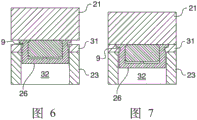
图6和图7是顺序剖视图,图中示出了将图5所示的紧固件组件安装到主体对象的方法。6 and 7 are sequential cross-sectional views illustrating a method of installing the fastener assembly shown in FIG. 5 to a subject object.
具体实施方式Detailed ways
图1和图2示出了根据一个优选实施例的齐平安装的物件保持紧固件8。所述紧固件8通常包括具有中心孔16和中心垂直轴线10的主本体11。本体11具有基本上圆柱形的形状、轴向延伸的侧壁6以及横向延伸的底部的端壁17。中心孔16是圆柱形并且由侧壁6和横向端壁17的内表面限定。所述主本体可包括主体对准装置12。其他优选实施例不包括对准装置12。Figures 1 and 2 illustrate a flush mounted
在图1至图7所示的实施例中,主体对准装置12包括两个空隙,这两个空隙形成于侧壁6紧邻横向端壁17的底部部分的外表面的相对侧。每个空隙均具有向外的径向面对的平的表面14和轴向面对的平的表面7。径向面对的表面14是平行的并且大致横向于横向端壁17的平面延伸。所述轴向面对的表面是共面的并且大致平行于横向端壁17的平面延伸。除了将紧固件8定位在主体对象内之外,当在所述孔中保持强力磁铁时,对准装置12为作业工具提供夹持点,用于牢固地操纵紧固件8。In the embodiment shown in FIGS. 1 to 7 , the body alignment means 12 includes two voids formed on opposite sides of the
本体11的顶部具有径向延伸的凸缘13,所述凸缘13具有内周13b,所述内周是与侧壁6的内表面连续的并且具有与侧壁6的内表面相同的直径。所述凸缘还具有外周13c,所述外周的直径大于侧壁6的外表面直径。凸缘13包括从凸缘13的内周13b和孔16的开口轴向向上延伸的周边唇部15。所述本体还包括周边铆接底切部9,所述底切部位于侧壁6的外表面并且位于凸缘13下面。The top of the
在优选的实施例中,唇部15具有外表面15a,所述外表面沿向上方向向内渐缩并且具有三角形的横截面。如下所述,所述唇部的横截面大致等于凸缘13的内周13b与所述物件上的倒角22(在以下进行描述)之间的空隙24的体积。In a preferred embodiment, the
横向端壁17包括至少一个突起物19,所述突起物在孔16内轴向地向上突出。在优选的实施例中,突起物19包括与横向端壁17一体成型的圆柱形突起。然而,只要在组装过程期间可控制变形,突起物19可具有任何形状。突起物19作用成可变形的间隙调整元件,如图4所示的安装之后,所述间隙调整元件确保被保持的物件18在唇部15与突起物19之间的过盈配合。突起物19补偿了公差变化并且确保当物件18被安装在紧固件8内时,被保持的物件18的上表面18a(通常是有效表面)与凸缘13的上表面13a完全齐平。The
图3和图4依次序示出了根据本发明的优选实施例的将诸如磁铁的物件18组装在如图1和图2所示的紧固件8内的方法。在一个优选的实施例中,物件18的形状优选地与孔16的形状互补并且具有围绕所述物件18的顶部周边的倒角22。倒角22位于邻近唇部13的内周13b。如上所述,所述倒角22建立了径向空隙24,当藉由压机使唇部15向下和向内变形时,所述空隙接纳所述唇部15。Figures 3 and 4 sequentially illustrate a method of assembling an
参照图3,物件18最初被插入孔16中并且抵靠突起物19。物件18和突起物19的长度(轴向尺寸)被选择成使得物件18的上表面18a在压制之前不是与凸缘13的上表面13a齐平就是在所述上表面13a的上方。然后,松动的组件(紧固件和物件)位于冲压头21与砧座23之间。当压机被启动时,冲压头21首先接触唇部15并且使唇部15向内及向下变形进入空隙24。藉由所述冲压头,唇部15的外表面15a的渐缩使唇部15能够向内折叠。此外,唇部15的外表面15a的渐缩也使所述唇部的体积减小并且降低使所述唇部变形进入空隙24所需的冲压力。降低的冲压力更容易被控制并且降低对物件18和紧固件8的损坏。Referring to FIG. 3 , the
参照图4,当唇部15围绕物件18的倒角22折叠并且所述压机接触所述凸缘的上表面13a时,压机会停在一限定位置。在组装过程期间,突起物19也因唇部15压在物件18上的向下力而变形。所述突起物和所述唇部的变形在突起物19与唇部15之间形成过盈配合。当压机到达所述限定位置,突起物19的向上力确保在组装之后,在所有公差条件下,所述物件始终齐平。所述过盈配合还导致物件18抵抗旋转,用于需要固定、不可旋转的物件的应用。一旦组装过程完成后,物件18和紧固件8构成完成的紧固件组件26。Referring to Figure 4, when the
图5示出了没有选配对准装置12的单个紧固件组件26。使用上述组装过程,物件18完全保持在孔16内并且被刚性地保持在变形唇部15与变形突起物19之间。因此,物件18的有效顶部表面18a与唇部15的变形渐缩表面15a及凸缘13的上表面13a齐平。FIG. 5 shows a
图6和图7依次序示出了根据本发明的优选实施例的将紧固件组件26安装到主体对象31的方法。在一个优选的实施例中,所述主体对象是金属板,诸如铝板。参照图6,紧固件组件26最初被安装在本体对象31的通孔32中。然后,组件26位于冲压头21与砧座23之间。当压机被启动时,冲压头21迫使组件26向下并且迫使所述底切部进入通孔32。因为凸缘13的直径大于通孔32,所以凸缘使本体材料向下且径向向内位移进入底切部9。经移位的本体材料提供紧固件组件26与主体对象31的正向互锁。6 and 7 sequentially illustrate a method of mounting the
以上描述被认为仅仅是对本发明的原理和可能的实施例的说明。更进一步地,因为很多的修改和变化对于本领域技术人员来说是很容易想到的,因此,不希望将本发明限定为附图所示的和描述的确切的结构和操作。因此,将所有适当的改进和等同物看作为包括在本发明的保护范围内,本发明的范围应当仅由下述的权利要求及其合法等同物来确定。The foregoing description is to be considered merely illustrative of the principles and possible embodiments of the present invention. Further, since many modifications and variations will readily occur to those skilled in the art, it is not intended to limit the invention to the precise construction and operation shown and described in the accompanying drawings. Accordingly, all appropriate modifications and equivalents are considered to be included within the scope of this invention, which should be determined only by the following claims and their legal equivalents.
Claims (20)
Applications Claiming Priority (3)
| Application Number | Priority Date | Filing Date | Title |
|---|---|---|---|
| US201562214037P | 2015-09-03 | 2015-09-03 | |
| US62/214,037 | 2015-09-03 | ||
| PCT/US2016/050116 WO2017040934A1 (en) | 2015-09-03 | 2016-09-02 | Flush-mount, article-retaining fastener |
Publications (2)
| Publication Number | Publication Date |
|---|---|
| CN108349552A CN108349552A (en) | 2018-07-31 |
| CN108349552B true CN108349552B (en) | 2020-09-01 |
Family
ID=58188500
Family Applications (1)
| Application Number | Title | Priority Date | Filing Date |
|---|---|---|---|
| CN201680064202.XA Active CN108349552B (en) | 2015-09-03 | 2016-09-02 | Flush mounted article retention fastener |
Country Status (11)
| Country | Link |
|---|---|
| US (1) | US10533592B2 (en) |
| EP (1) | EP3344523B1 (en) |
| JP (1) | JP6765423B2 (en) |
| CN (1) | CN108349552B (en) |
| CA (1) | CA2997419C (en) |
| HU (1) | HUE055481T2 (en) |
| MX (1) | MX394862B (en) |
| MY (1) | MY193856A (en) |
| PL (1) | PL3344523T3 (en) |
| TW (1) | TWI716444B (en) |
| WO (1) | WO2017040934A1 (en) |
Families Citing this family (4)
| Publication number | Priority date | Publication date | Assignee | Title |
|---|---|---|---|---|
| US10578140B2 (en) * | 2014-07-08 | 2020-03-03 | James Blake PORTER | Magnetic fasteners and related articles and methods |
| JP6873372B2 (en) * | 2018-09-11 | 2021-05-19 | 日立Astemo株式会社 | Support structure |
| US12460479B2 (en) | 2020-10-06 | 2025-11-04 | Little Giant Ladder Systems, Llc | Top cap and accessory tray for ladders and ladders incorporating same |
| CN118893141B (en) * | 2024-10-09 | 2024-12-24 | 湖南瑞丰磁电科技有限公司 | A stamping die and stamping method for producing and processing magnetic blocks |
Citations (5)
| Publication number | Priority date | Publication date | Assignee | Title |
|---|---|---|---|---|
| US3009225A (en) * | 1959-10-13 | 1961-11-21 | Monarch Tool & Machinery Co | Separable two-part magnetic connector |
| US5983464A (en) * | 1997-12-16 | 1999-11-16 | Bauer; Irving | Magnetic fastener |
| US6164168A (en) * | 1999-05-11 | 2000-12-26 | Anderson; Wayne | Tool magnet holder |
| CN101516225A (en) * | 2006-07-24 | 2009-08-26 | 维-弗莱克斯有限公司 | Portable item holder and method for using the holder |
| US8464377B1 (en) * | 2008-09-19 | 2013-06-18 | Michelle Leigh Carson | Linen fastener |
Family Cites Families (28)
| Publication number | Priority date | Publication date | Assignee | Title |
|---|---|---|---|---|
| JPS474369U (en) * | 1971-02-08 | 1972-09-09 | ||
| US3871264A (en) * | 1971-08-17 | 1975-03-18 | Robert L Hallock | Driven fastener for limited penetration of metal |
| JPS5241156A (en) * | 1975-09-30 | 1977-03-30 | Matsuo Mawaki | Method of connecting metal bar with metal plate |
| JPS557938U (en) * | 1978-06-29 | 1980-01-19 | ||
| US4265002A (en) * | 1979-08-13 | 1981-05-05 | Hosken James C | Magnetic fastening means |
| GB2063343B (en) | 1979-10-31 | 1984-03-14 | Tohpo Co Ltd | Magnetic fastening |
| JPS60169809U (en) * | 1984-04-20 | 1985-11-11 | 加藤発条株式会社 | Fixed structure of magnetic body |
| JPS61125004U (en) * | 1985-01-24 | 1986-08-06 | ||
| DE3522461A1 (en) * | 1985-06-22 | 1987-01-02 | Roland Man Druckmasch | MOUNTING OF RUNNERS |
| JP3300176B2 (en) * | 1994-09-29 | 2002-07-08 | 株式会社ニフコ | Magnet bracket |
| JP2002503557A (en) | 1998-02-17 | 2002-02-05 | コスマ インターナショナル インコーポレイテッド | Self-extruded bush assembly and method of forming the same |
| JP3546734B2 (en) * | 1998-12-28 | 2004-07-28 | コクヨ株式会社 | Magnet holder |
| DE10008262B4 (en) * | 2000-02-23 | 2007-03-15 | Röhm Gmbh | Method for producing carbide inserts as clamping jaws having chucks for chuck, and correspondingly produced clamping jaws |
| DE10032331C1 (en) * | 2000-07-04 | 2001-09-13 | Bosch Gmbh Robert | The mechanical coupling bond between the ends of two tubular workpieces has a swallowtail contour at their ends for one to be pushed into the other and the outer bent edge is forced back inwards |
| JP2004085533A (en) * | 2002-07-02 | 2004-03-18 | Ntn Corp | Magnetic encoder and wheel bearing equipped with it |
| JP2004360860A (en) * | 2003-06-06 | 2004-12-24 | Mitsubishi Electric Corp | Snap-fit mechanism |
| JP2005034857A (en) * | 2003-07-17 | 2005-02-10 | Aisin Seiki Co Ltd | Caulking member and caulking method |
| US7986206B2 (en) * | 2007-09-04 | 2011-07-26 | Avaya Inc. | Magnet cap |
| WO2009126703A1 (en) * | 2008-04-09 | 2009-10-15 | Pem Management, Inc. | Plastic-metal hybrid standoff |
| US20100101492A1 (en) | 2008-10-29 | 2010-04-29 | Kissak Sarajian | Reusable High-Temperature Resistant Masking System |
| DE102011012283B4 (en) * | 2011-02-24 | 2014-08-07 | Kathrein-Werke Kg | Holding and anchoring device on a metal plate for attachment of a functional carrier |
| WO2013029049A2 (en) | 2011-08-25 | 2013-02-28 | Iomounts Llc | Apparatus and methods for supporting an article |
| DE102012102286A1 (en) * | 2012-03-19 | 2013-09-19 | Thyssenkrupp Steel Europe Ag | A method of bonding a composite sheet to a metallic substrate |
| JP5996464B2 (en) * | 2013-03-21 | 2016-09-21 | 日立オートモティブシステムズ株式会社 | Method of manufacturing rotation angle detection device |
| US9243655B2 (en) * | 2013-06-13 | 2016-01-26 | GM Global Technology Operations LLC | Elastic attachment assembly and method of reducing positional variation and increasing stiffness |
| US20150086265A1 (en) * | 2013-09-26 | 2015-03-26 | GM Global Technology Operations LLC | Serviceable aligning and self-retaining elastic arrangement for mated components and method |
| US9371851B2 (en) * | 2014-01-15 | 2016-06-21 | Szuba Consulting, Inc. | Method of forming joint for interconnecting adjacent elements and joint formed thereby |
| KR102342932B1 (en) * | 2014-02-04 | 2021-12-24 | 부트벨딩 에스아 | Connector and method of using the same |
-
2016
- 2016-09-02 MX MX2018002763A patent/MX394862B/en unknown
- 2016-09-02 HU HUE16843068A patent/HUE055481T2/en unknown
- 2016-09-02 CA CA2997419A patent/CA2997419C/en active Active
- 2016-09-02 EP EP16843068.4A patent/EP3344523B1/en active Active
- 2016-09-02 US US15/255,636 patent/US10533592B2/en active Active
- 2016-09-02 JP JP2018522623A patent/JP6765423B2/en active Active
- 2016-09-02 WO PCT/US2016/050116 patent/WO2017040934A1/en not_active Ceased
- 2016-09-02 PL PL16843068T patent/PL3344523T3/en unknown
- 2016-09-02 MY MYPI2018002185A patent/MY193856A/en unknown
- 2016-09-02 CN CN201680064202.XA patent/CN108349552B/en active Active
- 2016-09-02 TW TW105128600A patent/TWI716444B/en active
Patent Citations (5)
| Publication number | Priority date | Publication date | Assignee | Title |
|---|---|---|---|---|
| US3009225A (en) * | 1959-10-13 | 1961-11-21 | Monarch Tool & Machinery Co | Separable two-part magnetic connector |
| US5983464A (en) * | 1997-12-16 | 1999-11-16 | Bauer; Irving | Magnetic fastener |
| US6164168A (en) * | 1999-05-11 | 2000-12-26 | Anderson; Wayne | Tool magnet holder |
| CN101516225A (en) * | 2006-07-24 | 2009-08-26 | 维-弗莱克斯有限公司 | Portable item holder and method for using the holder |
| US8464377B1 (en) * | 2008-09-19 | 2013-06-18 | Michelle Leigh Carson | Linen fastener |
Also Published As
| Publication number | Publication date |
|---|---|
| CN108349552A (en) | 2018-07-31 |
| MX2018002763A (en) | 2018-12-10 |
| MX394862B (en) | 2025-03-24 |
| WO2017040934A1 (en) | 2017-03-09 |
| TW201719030A (en) | 2017-06-01 |
| PL3344523T3 (en) | 2021-12-06 |
| JP2019509434A (en) | 2019-04-04 |
| CA2997419C (en) | 2023-08-08 |
| EP3344523A1 (en) | 2018-07-11 |
| JP6765423B2 (en) | 2020-10-07 |
| EP3344523A4 (en) | 2019-05-15 |
| EP3344523B1 (en) | 2021-06-02 |
| US10533592B2 (en) | 2020-01-14 |
| US20170067496A1 (en) | 2017-03-09 |
| TWI716444B (en) | 2021-01-21 |
| MY193856A (en) | 2022-10-28 |
| HUE055481T2 (en) | 2021-11-29 |
| CA2997419A1 (en) | 2017-03-09 |
Similar Documents
| Publication | Publication Date | Title |
|---|---|---|
| JP4137792B2 (en) | Nut plate | |
| CN108349552B (en) | Flush mounted article retention fastener | |
| US7306418B2 (en) | Deforming member and captive fastener retaining method | |
| CN101595314B (en) | Nut plate fastener assembly for composite materials | |
| CA2743840C (en) | Piercing standoff | |
| US7594788B2 (en) | Clinch/broach connector | |
| US9746019B2 (en) | Cylindrical object locking device and method | |
| US10612611B2 (en) | Carrier body for a brake pad of a disk brake with absorber mass for changing the vibration | |
| US10428847B2 (en) | Tapered head clinch fastener | |
| EP2199627A2 (en) | Blind rivet assembly | |
| JP7200216B2 (en) | Insert fastener with compression sleeve | |
| JP7558162B2 (en) | Fasteners for thin sheet materials | |
| TW201722576A (en) | Thin-sheet clinch fastener | |
| JP7077662B2 (en) | How to fix the insert and the inorganic plate | |
| JP2024513344A (en) | Self-clinching and self-piercing structural elements with multipurpose pilots |
Legal Events
| Date | Code | Title | Description |
|---|---|---|---|
| PB01 | Publication | ||
| PB01 | Publication | ||
| SE01 | Entry into force of request for substantive examination | ||
| SE01 | Entry into force of request for substantive examination | ||
| GR01 | Patent grant | ||
| GR01 | Patent grant |