CN108349176B - Method and apparatus for applying a member for sealing an inflatable article - Google Patents
Method and apparatus for applying a member for sealing an inflatable article Download PDFInfo
- Publication number
- CN108349176B CN108349176B CN201680066598.1A CN201680066598A CN108349176B CN 108349176 B CN108349176 B CN 108349176B CN 201680066598 A CN201680066598 A CN 201680066598A CN 108349176 B CN108349176 B CN 108349176B
- Authority
- CN
- China
- Prior art keywords
- container
- valve
- outlet
- inlet
- socket
- Prior art date
- Legal status (The legal status is an assumption and is not a legal conclusion. Google has not performed a legal analysis and makes no representation as to the accuracy of the status listed.)
- Active
Links
Images


Classifications
-
- B—PERFORMING OPERATIONS; TRANSPORTING
- B29—WORKING OF PLASTICS; WORKING OF SUBSTANCES IN A PLASTIC STATE IN GENERAL
- B29C—SHAPING OR JOINING OF PLASTICS; SHAPING OF MATERIAL IN A PLASTIC STATE, NOT OTHERWISE PROVIDED FOR; AFTER-TREATMENT OF THE SHAPED PRODUCTS, e.g. REPAIRING
- B29C73/00—Repairing of articles made from plastics or substances in a plastic state, e.g. of articles shaped or produced by using techniques covered by this subclass or subclass B29D
- B29C73/16—Auto-repairing or self-sealing arrangements or agents
- B29C73/166—Devices or methods for introducing sealing compositions into articles
-
- B—PERFORMING OPERATIONS; TRANSPORTING
- B29—WORKING OF PLASTICS; WORKING OF SUBSTANCES IN A PLASTIC STATE IN GENERAL
- B29C—SHAPING OR JOINING OF PLASTICS; SHAPING OF MATERIAL IN A PLASTIC STATE, NOT OTHERWISE PROVIDED FOR; AFTER-TREATMENT OF THE SHAPED PRODUCTS, e.g. REPAIRING
- B29C73/00—Repairing of articles made from plastics or substances in a plastic state, e.g. of articles shaped or produced by using techniques covered by this subclass or subclass B29D
- B29C73/02—Repairing of articles made from plastics or substances in a plastic state, e.g. of articles shaped or produced by using techniques covered by this subclass or subclass B29D using liquid or paste-like material
- B29C73/025—Repairing of articles made from plastics or substances in a plastic state, e.g. of articles shaped or produced by using techniques covered by this subclass or subclass B29D using liquid or paste-like material fed under pressure
-
- B—PERFORMING OPERATIONS; TRANSPORTING
- B29—WORKING OF PLASTICS; WORKING OF SUBSTANCES IN A PLASTIC STATE IN GENERAL
- B29L—INDEXING SCHEME ASSOCIATED WITH SUBCLASS B29C, RELATING TO PARTICULAR ARTICLES
- B29L2030/00—Pneumatic or solid tyres or parts thereof
Abstract
Device and method for dispensing and sealing an inflatable article, in particular a tyre, is provided from a container (5) having a valve (6), wherein the valve (6) has an inlet (7) and an outlet (8), the inlet (7) and outlet (8) being interconnected in a first position of the valve (6) and in a first position of the valve (6), and the outlet (8), the container (5) communicating only when required via the valve (6) to deliver a sealing member in a second position of the valve (6).
Description
Technical Field
The invention relates to a method for dispensing a device for sealing an inflatable article, in particular a tyre, from a container containing a valve having an inlet and an outlet, a source of compressed air being connected to the inlet and a connecting line for connecting to the connected inflatable article being connected to the outlet in a first position of the inlet and outlet of the valve, and a second position of the communication of the valve being produced between the inlet and the container and between the container and the outlet.
Background
Such devices and methods are known in various forms and designs. For example, if a tire of an automobile leaks and loses air, the tire or set of tires needs to be replaced. Changing tires is laborious and burdensome and, in particular, the spare tire occupies a considerable space in the trunk. Furthermore, there is additional fuel consumption due to the additional weight of the spare tire and the rim.
A tire repair kit may either be used only to inflate a tire or to seal and then inflate a tire. Depending on whether the tire is inflated only or sealed and inflated, the user connects the container with, for example, a compressor through a hose. In addition, the container may be omitted and only one hose may be connected to the compressor.
Depending on the connection configuration, air flows either directly from the compressor into the hose without re-routing through the container or from the air supply to the container, which requires mixing of the sealing medium from the container into the hose.
In the case of direct air flow, compressed air without a sealing member emerges from the outlet end of the hose, so that the device can also be used in a purely pneumatic corresponding connection configuration of the tire, which is intact.
When the air flow delivered by the compressor is re-routed through the container, the sealing member is pushed out of the container into the hose. Thus, the device in this communicating gas configuration can be used for sealing and subsequent inflation of a defective tire.
DE 202005021981U 1 describes a kit for inflating and repairing an inflatable article, and in particular a vehicle tire, which contains a compressor assembly, a container with a sealing liquid, and connecting means for connecting the container to the compressor assembly and the inflatable article to effect the article repair and inflation. The trim kit also includes an outer housing, wherein the outer housing houses the compressor assembly and defines a placement location for a container of sealing liquid. The container is removable from the placement location. By providing a connecting member for stably connecting the container to the compressor assembly, it should be noted that the container remains functionally connected to the compressor assembly when the container is removed from the placement location.
In DE 10106468 a1, the removal element has at least one valve which is switched between different positions. The first position is a complete closure of the inlet and outlet to the vessel. In the second position, the connecting conduit and the conduit to the interior of the container are open to expose the tire sealing member. Another position allows a direct connection from the inlet to the outlet without air passing through the container. In the switched-on position, which is achieved by a bypass, the air can be conveyed, for example, directly to inflate the tire. This can also be used for cleaning the connecting hose.
In order to eliminate the opening formed on the container for removing the tire sealant, a membrane, in particular a sealing membrane which can be opened via an inlet or an outlet or under high pressure, is provided on the container. Thus, only the valve needs to be switched to open in order to introduce air from the air source through the inlet into the container via the supply line. The tire sealant flows from the container into the tire via the connecting tube via the connecting conduit and the outlet. After the tire sealant has been applied, further inflation of the tire may be ensured, for example, by closing the valve and a bypass connecting the inlet to the outlet. At the same time, it is ensured that no more tire sealant can be released. Furthermore, the tire sealant remaining in the connecting pipe is removed.
When the device is inserted into the housing, the valve can be easily operated from the outside by means of a switching element, a gear shift lever, a rotary switch or the like. Only the switching element needs to be transferred in order to, for example, inject tire sealant into the tire.
Objects of the invention
It is an object of the invention to simplify the handling of the device according to the invention and to provide a simplified way of manufacturing thereof.
Solution to the object
To achieve this, the container valve is held, when required, only by the sealant in or on the socket of the valve.
This means that, for example, when only air is being delivered into the inflatable article (e.g., a tire), the sealant in the container is not in contact with the air. This has the great advantage that the sealant in the container has greater storage stability. When not needed, the sealant is not opened and thus air and/or impurities do not enter the container.
The valve is always in the first configuration or position in its default position or in the absence of an installed container, and preferably only passes through the container into the second configuration or position. Also, the present invention can give an aspect of simple and safe disposal.
Furthermore, in this position of the valve, the inlet and outlet are connected for direct transfer of air. When the sealant is used, the container is placed on the valve and in a horizontal position. The container and the valve are connected via a clamping connector so that the container is firmly seated in its resting position. A positioning device for the container is also provided. Therefore, the user cannot operate the apparatus of the present invention incorrectly.
The valve is brought into a second configuration or position by rotating the container with a portion of the valve. In this second position, a connection is established between the inlet and the container and between the container and the outlet, the container being inverted in this position. This greatly simplifies the handling of the entire tire repair kit and leaves no room for error.
Another great advantage of the invention is also that the valve and the container are kept separate from each other in the housing. This ensures that the valve is not suddenly activated and sealant flows from the container.
Also, both the valve and the container are protected in the housing, each of the valve and the container being protected by a separate lid. In this way, the container cannot fall out of the housing or there is no impurity blocking the valve.
In the above, a clamping connector ensuring a secure placement of the container has been discussed. Furthermore, providing a separate accessory to the container to hold the clamp connector provides the great advantage that only the container and/or the socket needs to be replaced, instead of replacing the entire tire repair kit, thus resulting in a huge cost saving.
The valve has an axis about which the switching element is rotatably mounted with respect to the receptacle socket, which enables two positions of the valve, which means that the valve can be activated by this rotation and then only the sealant is delivered to the inflatable article. Resulting in a simplified operation of the present invention.
The shaft is located in the housing and is traversed at least by one axial hole, wherein said axial hole is adapted for the passage of air in the first position of the valve, if necessary also via a bypass channel. In the second position of the valve, the axial bore is configured to communicate air into the container and the second axial bore is configured to communicate sealant out of the container.
All channels and lines are compactly accommodated in this one shaft, and the switching element achieves space saving. No free hose or the like is provided, but the user only needs to change the position of the container and the tire repair kit operates properly.
In the second position of the valve, when the container is perpendicular to the valve head, the valve is fixed in the preferred embodiment via a clamp connector. Thus, the container does not inadvertently tilt back into its first horizontal position and thus the sealing process is stopped at an early stage.
The connecting duct between the valve and the tyre enters the housing by means of an additional clamping connector. Thus, it is ensured that the duct is not easily blocked and safe transport of air or air and sealant to the tyre can take place.
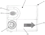
According to fig. 1, the device V of the invention for dispensing a member for sealing an inflatable module comprises a housing 1, wherein two removable covers 2.1 and 2.2 are arranged on the housing 1, the removable covers 2.1 and 2.2 being removable according to the directions of arrows 3.1 and 3.2.
Further, a pressure gauge 4 is shown on the housing, wherein the pressure gauge 4 indicates the pressure in the inflatable article, but is not further described herein, as the present invention does not detail the conventional components.
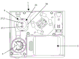
Fig. 2 shows the interior of the housing 1. The container 5 filled with sealant is located under the cover 2.2 in the closed state of the housing 1, and the valve 6 is located under the cover 2.1 in the closed state of the housing 1. The compressor for compressing the air and the connection to the on-board network of the passenger car are not described.
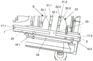
According to fig. 3 to 9, the valve 6 has an inlet 7 and an outlet 8. A source of compressed air (in particular, a compressor), not further described, is connected to the inlet 7 and a hose 9 or a corresponding connecting duct for connection to the inflatable article is connected to the outlet 8.
Fig. 3 shows the device according to the invention in a position of use, referred to as the first position. For this purpose, after removal of the cover 2.1, the valve 6 is tilted in the housing 1 and the container 5 is fastened on the valve 6 in a horizontal position. In this first position, only compressed air is supplied from the inlet 7 to the outlet 8.
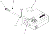
According to fig. 4, the container 5 is brought into a second position, wherein in the second position the container 5 is perpendicular to the valve head, such that the sealant located therein flows downwards. In this second position, the compressed air sealant is fed through the hose 9 into the valve (not shown) of the inflatable article.
According to fig. 4 and 10, the hose 9 has a rotating sleeve 10 at one end to be screwed onto the valve. The other end shows the joint 11 and the clamping connectors 12.1 and 12.2.
The nipple 11 of the hose 9 is inserted laterally into an opening 13 in the housing 1. The clamp connectors 12.1 and 12.2 fix the hose 9 by clamping in the grooves 14.1 and 14.2, wherein the grooves 14.1 and 14.2 are located next to the opening 13.
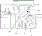
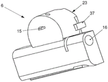
For the connection to the valve 6, the connecting head 22, which is also shown in fig. 3 in particular, is first screwed onto the container 5, wherein the connecting head 22 has a corresponding internal thread, which is screwed onto the external thread 21 of the container. The connector 22 is inserted into a socket 23 of the valve, the socket 23 having a passage 16, and a shaft 24 located in the passage 16. The socket 23 rotates about this axis 24, wherein the axis 24 is arranged in a fixed manner in the housing 1. The inlet 7 and the outlet 8 are respectively provided at one end of the shaft 24.
In order to rotate the shaft 24, two bearing blocks 26.1 and 26.2 project from the bottom 25 of the housing 1.
In the socket 23, according to fig. 2, two projecting connecting heads 27.1 and 27.2 are provided, wherein two bush sections 28.1 and 28.2 of the connecting head 22 can be placed on the two projecting connecting heads 27.1 and 27.2. In this way, the two ducts 29.1 and 29.2 in the socket 23 are connected to the inside of the container 5. These ducts 29.1 and 29.2 lead to openings 30.1 or 30.2 (see fig. 7) respectively to transverse channels 31.1 or 31.2 in the socket 23. These transverse channels are each closed at one end by a respective plug 32.1 and 32.2.
The shaft 24 has axial bores 17.1 and 17.2 on the inlet 7 and outlet 8 sides, respectively, wherein the axial bores 17.1 and 17.2 are separated from one another by an intermediate piece 33. According to fig. 7, the transverse bore 18.1 branches off from the axial bore 17.1 and the transverse bore 18.1 opens into a bypass channel 34 in the socket 23, wherein the bypass channel 34 bridges the two axial bores 17.1 and 17.2. This bypass channel 34 then likewise has a transition to the other transverse bore 18.2, wherein the transverse bore 18.2 leads to the axial bore 17.2.
A further transverse bore 19.1 is provided at the end of the axial bore 17.1, radially offset with respect to the transverse bore 18.1, wherein, according to the figure, in the second position of the valve 6, the further transverse bore 19.1 opens into the transverse channel 31.1. The axial bore 17.1 is then connected to the interior of the container 5 through the opening 30.1 and the channel 29.1 and the bushing portion 28.1. Likewise, the axial bore 17.2 has at its inner end a further transverse bore 19.2, wherein the transverse bore 19.2 is arranged offset with respect to the transverse bore 18.2 in the shaft 24. The transverse bore 19.2 is connected to the transverse channel 31.2. Via the opening 30.2, this channel thus has a connection into the interior of the container 5 via the channel 29.2 and the bush portion 28.2.
The operation of the invention is as follows:
a source of compressed air, a container 5 and a valve 6 are located in the housing 1. The housing 1 can likewise be inserted into the trunk of a vehicle, for example.
If sealant from the container 5 is used due to deflation of the tires, the caps 2.1 and 2.2 are removed from the housing 1 and the container 5 is removed from the housing 1. Optionally, the existing sealing membrane is removed from the container 5.
The coupling head 22 is then screwed onto the container 5. This connection head 22 has a centering projection 35 (see fig. 3), wherein the centering projection 35 ensures a correct desired placement of the connection head 22 on the receptacle 23, so that the bushing portions 28.1 and 28.2 also find the corresponding connection heads 27.1 and 27.2. For this purpose, the edge of the socket 23 has a cutout 36.
Furthermore, two clamp hooks 37 project from the socket 23 on both sides of the socket 23, only one of which is shown in the figure. When the connector 22 is placed on the socket 23, these clip hooks 37 latch into corresponding grooves formed laterally in the socket 23. This results in a good connection between the container 5 and the valve 6.
If in the first position shown in fig. 3 only compressed air needs to be introduced into the inflatable article, the valve constituted by the socket 23 and the shaft 24 is in the position shown in fig. 7. Compressed air is introduced through the inlet 7, for example by a compressor, which is also positioned in the housing 1. The compressed air reaches the outlet 8 via the transverse bore 18.1, the bypass channel 34, the transverse bore 18.2 and the axial bore 17.2, wherein the outlet 8 is connected to the hose 9.
However, if sealant is to be introduced from the container 5 into the inflatable article, the bottle body is vertically rotated by 90 ° as shown in fig. 4. In this condition, the socket 23 rotates about the shaft 24 and reaches the position shown in fig. 8. In this case, the transverse bores 18.1 and 18.2 are closed to the bypass channel 34, but a connection is formed between the transverse bore 31.1 and the axial bore 17.1 via the transverse bore 19.1 and a connection is formed between the transverse bore 31.2 and the axial bore 17.2 via the transverse bore 19.2. Thus, air enters the interior of the container 5 via the inlet 7, the axial bore 17.1, the transverse bore 19.1, the transverse channel 31.1, the opening 30.1, the channel 29.2, the connection head 27.1, the bushing portion 28.1 and the holes in these two elements respectively, and thus pressurizes the sealant. The sealant is now delivered via the bush 28.2, the connection 27.2 or the holes integrated in these two elements, through the channel 29.2, the opening 30.2, the transverse channel 31.2, the transverse hole 19.2 and the axial hole 17.2 to the outlet 8, through the hose 9 to the inflatable article.
In order to maintain the valve 6 in this second position, a further connecting clamp 15 (see fig. 9) is provided on the underside of the socket 23, which connecting clamp 15 is in the second position of the valve 6, as shown in fig. 5 and 6.
List of reference numerals
1 casing
2 cover
3 arrow in the direction of
4 pressure gauge
5 Container
6 valve
7 inlet
8 outlet
9 connecting pipe/hose
10 rotating bushing
11 joint
12 clamping connector
13 opening
14 groove
15 connecting clamp
16 channels
17 axial hole
18 transverse bore
19 transverse bore
20 sealing ring
21 screw thread
22 connector
23 socket
24 shaft
25 bottom plate
26 bearing seat
27 connecting head
28 lining part
29 channel
30 opening
31 transverse channel
32 plug
33 center piece
34 bypass channel
35 centering projection
36 positioning device
37 clamping connection
38 bracket
V-arrangement
Claims (28)
1. A method of dispensing a sealant for sealing an inflatable article from a container (5) associated with a valve (6), the valve (6) having an inlet (7) and an outlet (8), a source of compressed air being connected to the inlet (7) and a connecting line (9) for connection to the inflatable article being connected to the outlet (8), and, in a first position of the valve (6), the inlet (7) and the outlet (8) being connected to one another, and, in a second position of the valve (6), a connection being established between the inlet (7) and the container (5) and between the container (5) and the outlet (8), wherein the container (5) is secured to the valve (6) in or on a socket (23) of the valve (6) only when sealant is required, wherein the valve (6) is brought from the first position into the second position by the container (5), and
the valve (6) is in the first position before the connection with the container (5), in which first position the inlet (7) and the outlet (8) are used for the direct transfer of air, the container (5) is in a substantially horizontal position, but then, by rotating the container (5) together with a part of the valve (6), the valve (6) is brought into the second position, in which second position the connection is made between the inlet (7) and the container (5) and between the container (5) and the outlet (8), the container (5) being inverted in this position.
2. Method according to claim 1, wherein the receptacle (23) receives a clamping connection (37) with the container (5) and/or provides a positioning means (35, 36) for the container (5).
3. The method according to claim 1 or 2, wherein the container (5) and the valve (6) are housed separately from each other in a housing (1).
4. A method according to claim 3, wherein the valve (6) and/or the container (5) are covered in the housing (1) by a removable cover (2.1, 2.2).
5. The method of claim 1, wherein the inflatable article is a tire.
6. A device for dispensing a sealant for sealing an inflatable article from a container (5) associated with a valve (6), the valve having an inlet (7) and an outlet (8), a compressed air source being connectable to the inlet (7) and a connecting line (9) for connecting to the inflatable article being connectable to the outlet (8), and, in a first position of the valve (6), the inlet (7) and the outlet (8) being connectable to one another, and, in a second position of the valve (6), a connection being producible between the inlet (7) and the container (5) and between the container (5) and the outlet (8), wherein the valve (6) has a socket (23), the socket (23) being for releasably fixing the container (5),
wherein the valve (6) has an axis (24), a switching element being rotatably arranged with the socket (23) around the axis (24) to produce the first and second positions of the valve (6), and
wherein the receptacle (23) of the container (5) is arranged on the switching element.
7. The device of claim 6, wherein the inflatable article is a tire.
8. Device according to claim 6, wherein the container (5) together with the socket comprises a clamping connection (37).
9. Device according to claim 8, wherein a separate connecting head (22) is assigned to the container to produce the clamping connection (37).
10. Device according to claim 9, wherein the socket (23) and the connector (22) each have at least two connections by means of a connector (27.1, 27.2) and a bushing portion (28.1, 28.2) which can be mated with each other.
11. The device according to any of claims 6 to 10, wherein at least one axial hole (17.1, 17.2) penetrates at least partially the shaft (24), in the second position of the valve (6) a first axial hole (17.1) being arranged for conveying air into the container (5) and a second axial hole (17.2) for conveying sealant out of the container (5).
12. The device according to claim 6, wherein the valve (6) is fixable in its second position by clamping the connection (37).
13. The device according to claim 6, wherein the container (5) and the valve (6) are located in a housing (1), and
wherein the shaft (24) of the valve (6) is fixed in the housing (1).
14. The device according to claim 13, wherein the valve (6) and/or the container (5) are covered by a removable cap (2.1, 2.2).
15. Device according to claim 13, wherein at least the connection line (9) between the valve (6) and the inflatable article is connected to the housing (1) by means of a clamping connection.
16. A device for dispensing a sealant from a container into an inflatable article, the device having a valve with an inlet (7) and an outlet (8), a source of compressed air being connectable to the inlet (7) and a connecting line (9) for connection to the inflatable article being connectable to the outlet (8), wherein, in a first position of the valve (6), the inlet (7) and the outlet (8) are connected to each other and, in a second position of the valve (6), a connection is established between the inlet (7) and the container (5) and between the container (5) and the outlet (8), wherein the valve (6) has a socket (23) for releasably securing the container (5), the container (5) being releasably secured to the socket (23) by connection to a separate connecting head (22), the connector head (22) is configured to be fixed to the socket (23) with a pair of clamping connections (37) on the socket (23), wherein the valve (6) has a shaft (24), wherein a switching element is rotatably arranged around the shaft (24) together with the socket (23) to switch between the first position of the valve (6) and the second position of the valve (6), and wherein the socket (23) for the container is arranged on the switching element.
17. Device according to claim 16, wherein the container (5) has a clamping connection (37) with the socket.
18. Device according to claim 16, wherein the socket (23) and the connector head (22) each have at least two connections by means of a connector head (27.1, 27.2) and a bushing portion (28.1, 28.2) configured to cooperate with each other.
19. The device according to claim 16, wherein a first axial hole (17.1) and a second axial hole (17.2) at least partially penetrate the shaft (24), the first axial hole (17.1) being arranged for conveying air into the container (5) and the second axial hole (17.2) for conveying sealant out of the container (5) in the second position of the valve (6).
20. Device according to claim 16, wherein the valve (6) is fixed in its second position by clamping the connection (37).
21. The device according to claim 16, wherein the container (5) and the valve (6) are located in a housing (1).
22. The device according to claim 21, wherein the shaft (24) of the valve (6) is fixed in the housing (1).
23. The device according to claim 21, wherein the valve (6) and the container (5) are each covered by a removable cap (2.1, 2.2), respectively.
24. Device according to claim 21, wherein at least the connection line (9) between the valve (6) and the inflatable article is connected to the housing (1) by means of a clamping connection.
25. A method for dispensing sealant from a container (5) into an inflatable article, the method using the device of claim 16, the method comprising:
-connecting the source of compressed air to the inlet (7) of the valve (6);
connecting a first end of the connecting line (9) to the outlet (8) of the valve (6);
connecting a second end of the connecting line (9) to the inflatable article;
-connecting the container (5) to the socket (23) of the valve (6) when the valve is in the first position, so that the container (5) is in a horizontal position;
bringing the valve (6) into the second position by rotating the container (5) into an inverted position;
wherein, when the valve (6) is in the first position, only compressed air is supplied to the inflatable article from the compressed air source via the inlet (7), the outlet (8) and the connecting line (9); and the number of the first and second electrodes,
wherein, when the valve (6) is in the second position, compressed air is supplied from the compressed air source to the container (5) via the inlet (7) and compressed air sealant is subsequently supplied from the container (5) to the inflatable article via the outlet (8) and the connecting line (9).
26. Method according to claim 25, wherein the receptacle (23) receives and positions the container (5) with a clamping connection (37).
27. The method according to claim 25, wherein the container (5) and the valve (6) are housed separately from each other in a housing (1).
28. The method according to claim 27, wherein the valve (6) and the container (5) are each covered in the housing (1) by a separate removable cover (2.1, 2.2), respectively.
Applications Claiming Priority (3)
| Application Number | Priority Date | Filing Date | Title |
|---|---|---|---|
| DE102015119917.3A DE102015119917A1 (en) | 2015-11-18 | 2015-11-18 | Method and device for dispensing a means for sealing an inflatable article |
| DE102015119917.3 | 2015-11-18 | ||
| PCT/IB2016/056984 WO2017085695A1 (en) | 2015-11-18 | 2016-11-18 | A method and apparatus for applying a means for sealing an inflatable article |
Publications (2)
| Publication Number | Publication Date |
|---|---|
| CN108349176A CN108349176A (en) | 2018-07-31 |
| CN108349176B true CN108349176B (en) | 2021-01-29 |
Family
ID=57471940
Family Applications (1)
| Application Number | Title | Priority Date | Filing Date |
|---|---|---|---|
| CN201680066598.1A Active CN108349176B (en) | 2015-11-18 | 2016-11-18 | Method and apparatus for applying a member for sealing an inflatable article |
Country Status (7)
| Country | Link |
|---|---|
| US (1) | US10926495B2 (en) |
| EP (1) | EP3377310B1 (en) |
| JP (1) | JP6889157B2 (en) |
| KR (1) | KR102516631B1 (en) |
| CN (1) | CN108349176B (en) |
| DE (1) | DE102015119917A1 (en) |
| WO (1) | WO2017085695A1 (en) |
Families Citing this family (9)
| Publication number | Priority date | Publication date | Assignee | Title |
|---|---|---|---|---|
| JP7015550B2 (en) * | 2016-02-17 | 2022-02-03 | トライデル リサーチ プロプリエタリー リミテッド | Improved equipment for sealing and inflating damaged inflatable items such as flat tires |
| US10926591B2 (en) | 2019-04-17 | 2021-02-23 | Santa Cruz Bicycles, LLC | Inflation system for tubeless tires |
| DE102019217775A1 (en) | 2019-11-19 | 2021-05-20 | Continental Reifen Deutschland Gmbh | Device for transporting compressed air and / or sealant into a pneumatic vehicle tire and portable / transportable system for sealing and inflating pneumatic vehicle tires |
| CN115210490A (en) | 2020-01-27 | 2022-10-18 | 约翰·昆塔纳 | Improved pneumatic valve system and method of use |
| JP1678210S (en) * | 2020-06-18 | 2021-02-01 | ||
| USD959498S1 (en) * | 2020-09-04 | 2022-08-02 | Sumitomo Rubber Industries, Ltd. | Compressor |
| US11794426B2 (en) | 2021-06-30 | 2023-10-24 | Illinois Tool Works Inc. | Flat tire repair device |
| USD956826S1 (en) * | 2021-06-30 | 2022-07-05 | Illinois Tool Works Inc. | Flat tire repair kit |
| DE102022100812A1 (en) * | 2022-01-14 | 2023-07-20 | Illinois Tool Works Inc. | COMPRESSOR ASSEMBLY FOR DEMAND INFLATION AND/OR REPAIR OF INFLATABLE ARTICLES OR PRODUCTS |
Family Cites Families (30)
| Publication number | Priority date | Publication date | Assignee | Title |
|---|---|---|---|---|
| US3718238A (en) * | 1970-07-27 | 1973-02-27 | Polytop Corp | Safety dispensing closure |
| US3786964A (en) * | 1972-09-15 | 1974-01-22 | Eyelet Specialty Co | Safety mechanism for a liquid-dispensing container |
| US4081113A (en) * | 1976-03-11 | 1978-03-28 | Polytop Corporation | Child resistant dispensing closure |
| US5156853A (en) * | 1989-08-04 | 1992-10-20 | Werner Frank D | Windshield repair apparatus |
| GB9101560D0 (en) * | 1991-01-24 | 1991-03-06 | Boc Group Plc | Fluid delivery system |
| US5427145A (en) * | 1993-10-07 | 1995-06-27 | Abbott Laboratories | Connector with integral valve |
| US5687777A (en) * | 1996-03-11 | 1997-11-18 | Ohmeda Inc. | Anesthetic agent filler valve |
| DE20122862U1 (en) | 2001-02-13 | 2008-09-11 | Doukas Ag | Device for dispensing tire sealant |
| PL202965B1 (en) * | 2001-02-16 | 2009-08-31 | Continental Ag | Device for sealing and inflating an inflatable object |
| ITTO20040117A1 (en) | 2004-02-27 | 2004-05-27 | Tek Srl | INFLATION AND REPAIR KIT FOR INFLATABLE ITEMS, IN PARTICULAR TIRES |
| JP2008143099A (en) * | 2006-12-12 | 2008-06-26 | Bridgestone Corp | Sealing pump-up apparatus |
| JP5376754B2 (en) * | 2006-12-21 | 2013-12-25 | 株式会社ブリヂストン | Sealing device |
| DE202007016242U1 (en) | 2007-11-21 | 2008-01-31 | Continental Aktiengesellschaft | Device with a switching mark for sealing and inflating inflatable objects |
| JP5054627B2 (en) * | 2008-07-15 | 2012-10-24 | 住友ゴム工業株式会社 | Sealing agent container lid unit |
| CN102186658B (en) * | 2008-10-20 | 2013-11-20 | 横滨橡胶株式会社 | Flat tire sealant storage container and flat tire repair device |
| CN102405132B (en) * | 2009-04-23 | 2014-02-26 | 株式会社普利司通 | Sealing/pump-up device |
| US7886783B2 (en) * | 2009-05-22 | 2011-02-15 | The General Electric Company | Anesthetic vaporizer filling system |
| DE102009060272B4 (en) | 2009-12-23 | 2022-11-10 | Sumitomo Rubber Industries Ltd. | Device for introducing air and/or sealant into a tire |
| TWI482908B (en) | 2011-03-07 | 2015-05-01 | Wen San Chou | Air compressor for vehicle |
| DE102011018927A1 (en) * | 2011-04-28 | 2012-10-31 | Sumitomo Rubber Industries, Ltd. | Device for introducing air and / or sealing means into a tire |
| JP5568068B2 (en) * | 2011-09-20 | 2014-08-06 | 住友ゴム工業株式会社 | Punk repair kit |
| JP5568100B2 (en) * | 2012-01-06 | 2014-08-06 | 住友ゴム工業株式会社 | Integrated puncture repair kit |
| PL2815875T3 (en) * | 2012-02-16 | 2018-12-31 | Wen-San Jhou | Vehicle-mounted air compressor device |
| US9302654B2 (en) | 2013-01-25 | 2016-04-05 | Illinois Tool Works Inc. | Device for dispensing tire sealant |
| CN203752543U (en) | 2013-11-22 | 2014-08-06 | 上海华汇机电有限公司 | Tire repairing liquid inflating pump switching device |
| JP6302545B2 (en) * | 2013-11-28 | 2018-03-28 | 住友ゴム工業株式会社 | Device and self-closing threaded joint for sealing and / or expanding objects |
| DE102013113618A1 (en) * | 2013-12-06 | 2015-06-11 | Sumitomo Rubber Industries, Ltd. | Device for introducing compressed air and / or sealing means into a tire |
| US20170173900A1 (en) * | 2014-02-06 | 2017-06-22 | Sumitomo Rubber Industries, Ltd. | Puncture repair kit |
| CN204278561U (en) | 2014-11-27 | 2015-04-22 | 王名宪 | Can inflate and the air compressor machine of tire patching |
| TWI647129B (en) * | 2015-04-23 | 2019-01-11 | 周文三 | Air compressor |
-
2015
- 2015-11-18 DE DE102015119917.3A patent/DE102015119917A1/en active Pending
-
2016
- 2016-11-18 US US15/776,947 patent/US10926495B2/en active Active
- 2016-11-18 KR KR1020187016685A patent/KR102516631B1/en active IP Right Grant
- 2016-11-18 JP JP2018525765A patent/JP6889157B2/en active Active
- 2016-11-18 EP EP16805519.2A patent/EP3377310B1/en active Active
- 2016-11-18 WO PCT/IB2016/056984 patent/WO2017085695A1/en active Application Filing
- 2016-11-18 CN CN201680066598.1A patent/CN108349176B/en active Active
Also Published As
| Publication number | Publication date |
|---|---|
| EP3377310A1 (en) | 2018-09-26 |
| US20180333927A1 (en) | 2018-11-22 |
| DE102015119917A1 (en) | 2017-05-18 |
| KR102516631B1 (en) | 2023-03-30 |
| CN108349176A (en) | 2018-07-31 |
| US10926495B2 (en) | 2021-02-23 |
| JP2019506308A (en) | 2019-03-07 |
| WO2017085695A1 (en) | 2017-05-26 |
| EP3377310B1 (en) | 2024-02-28 |
| KR20180084091A (en) | 2018-07-24 |
| JP6889157B2 (en) | 2021-06-18 |
Similar Documents
| Publication | Publication Date | Title |
|---|---|---|
| CN108349176B (en) | Method and apparatus for applying a member for sealing an inflatable article | |
| EP1722961B1 (en) | Container for sealing liquid for repairing inflatable articles, in particular tyres, and repair kit featuring such a container | |
| US7789110B2 (en) | Kit for inflating and repairing inflatable articles, in particular tyres | |
| KR101830997B1 (en) | Apparatus for the introduction of air and/or sealant into a tire | |
| NO322534B1 (en) | Device for sealing and inflating an inflatable object | |
| CN107405844A (en) | Portable maintenance external member | |
| AU2016201917A1 (en) | Pneumatic Valve Adaptor | |
| CN206589584U (en) | Tire connection valve and the maintenance tool bag for motor vehicle tire | |
| JP6370224B2 (en) | Backflow prevention device | |
| US10786958B2 (en) | Bottle cap and its usage method | |
| CN101868344B (en) | Apparatus comprising plug-in connection for sealing and pumping up inflatable objects | |
| CN102673531B (en) | Device using improved flow divider and capable of repairing and charging inflatable objects | |
| JPS6291816A (en) | Gas meter changing device | |
| CN116890471A (en) | Apparatus and system for delivering liquid sealant into inflatable articles | |
| CN105722669A (en) | Device for sealing and inflating inflatable objects | |
| CN105745062A (en) | Device for sealing and inflating inflatable objects, comprising a position-dependent valve |
Legal Events
| Date | Code | Title | Description |
|---|---|---|---|
| PB01 | Publication | ||
| PB01 | Publication | ||
| SE01 | Entry into force of request for substantive examination | ||
| SE01 | Entry into force of request for substantive examination | ||
| GR01 | Patent grant | ||
| GR01 | Patent grant |