CN108348630B - Fragrance providing device - Google Patents
Fragrance providing device Download PDFInfo
- Publication number
- CN108348630B CN108348630B CN201680060530.2A CN201680060530A CN108348630B CN 108348630 B CN108348630 B CN 108348630B CN 201680060530 A CN201680060530 A CN 201680060530A CN 108348630 B CN108348630 B CN 108348630B
- Authority
- CN
- China
- Prior art keywords
- fragrance
- holding
- holding member
- introduction port
- rotation
- Prior art date
- Legal status (The legal status is an assumption and is not a legal conclusion. Google has not performed a legal analysis and makes no representation as to the accuracy of the status listed.)
- Active
Links
Images


Classifications
-
- A—HUMAN NECESSITIES
- A61—MEDICAL OR VETERINARY SCIENCE; HYGIENE
- A61L—METHODS OR APPARATUS FOR STERILISING MATERIALS OR OBJECTS IN GENERAL; DISINFECTION, STERILISATION OR DEODORISATION OF AIR; CHEMICAL ASPECTS OF BANDAGES, DRESSINGS, ABSORBENT PADS OR SURGICAL ARTICLES; MATERIALS FOR BANDAGES, DRESSINGS, ABSORBENT PADS OR SURGICAL ARTICLES
- A61L9/00—Disinfection, sterilisation or deodorisation of air
- A61L9/015—Disinfection, sterilisation or deodorisation of air using gaseous or vaporous substances, e.g. ozone
- A61L9/04—Disinfection, sterilisation or deodorisation of air using gaseous or vaporous substances, e.g. ozone using substances evaporated in the air without heating
- A61L9/12—Apparatus, e.g. holders, therefor
- A61L9/125—Apparatus, e.g. holders, therefor emanating multiple odours
-
- A—HUMAN NECESSITIES
- A61—MEDICAL OR VETERINARY SCIENCE; HYGIENE
- A61L—METHODS OR APPARATUS FOR STERILISING MATERIALS OR OBJECTS IN GENERAL; DISINFECTION, STERILISATION OR DEODORISATION OF AIR; CHEMICAL ASPECTS OF BANDAGES, DRESSINGS, ABSORBENT PADS OR SURGICAL ARTICLES; MATERIALS FOR BANDAGES, DRESSINGS, ABSORBENT PADS OR SURGICAL ARTICLES
- A61L9/00—Disinfection, sterilisation or deodorisation of air
- A61L9/015—Disinfection, sterilisation or deodorisation of air using gaseous or vaporous substances, e.g. ozone
- A61L9/04—Disinfection, sterilisation or deodorisation of air using gaseous or vaporous substances, e.g. ozone using substances evaporated in the air without heating
- A61L9/12—Apparatus, e.g. holders, therefor
-
- A—HUMAN NECESSITIES
- A61—MEDICAL OR VETERINARY SCIENCE; HYGIENE
- A61L—METHODS OR APPARATUS FOR STERILISING MATERIALS OR OBJECTS IN GENERAL; DISINFECTION, STERILISATION OR DEODORISATION OF AIR; CHEMICAL ASPECTS OF BANDAGES, DRESSINGS, ABSORBENT PADS OR SURGICAL ARTICLES; MATERIALS FOR BANDAGES, DRESSINGS, ABSORBENT PADS OR SURGICAL ARTICLES
- A61L2209/00—Aspects relating to disinfection, sterilisation or deodorisation of air
- A61L2209/10—Apparatus features
- A61L2209/13—Dispensing or storing means for active compounds
- A61L2209/134—Distributing means, e.g. baffles, valves, manifolds, nozzles
Landscapes
- Health & Medical Sciences (AREA)
- Epidemiology (AREA)
- Life Sciences & Earth Sciences (AREA)
- Animal Behavior & Ethology (AREA)
- General Health & Medical Sciences (AREA)
- Public Health (AREA)
- Veterinary Medicine (AREA)
- Disinfection, Sterilisation Or Deodorisation Of Air (AREA)
Abstract
To provide a new and improved fragrance supply device which can be reduced in size. [ solution ] Provided is a fragrance providing device including: a fragrance holding member in which a plurality of holding passages each holding a fragrance are provided to penetrate the fragrance holding member; and a rotation mechanism capable of relatively rotating the fragrance holding member and a member provided with an introduction port communicating with the holding passage of the part of the plurality of holding passages and introducing air supplied from an air flow source to the holding passage of the part, thereby switching the holding passage of the part communicating with the introduction port.
Description
Technical Field
The present invention relates to a fragrance providing device.
Background
In recent years, for the purpose of, for example, providing plural types of perfumes, a technique involving a fragrance providing apparatus having plural spaces each accommodating a perfume has been proposed. Such a fragrance providing apparatus can provide a plurality of fragrances, for example, by having a plurality of spaces containing different types of fragrances.
For example, in order to reduce the size of the device itself, patent document 1 discloses an olfactory display that presents a fragrance in a limited time and space range, which includes: a housing having a dispensing opening; a plurality of fragrance chambers formed by dividing an inner space of the housing using partition walls; a solid fragrance source contained in at least one fragrance chamber; a plurality of air flow sources, each of which is provided in each fragrance chamber and blows air into the fragrance chamber by using a diaphragm provided with a piezoelectric element; and a plurality of fragrance channels, each fragrance channel extending from the fragrance chamber toward the emission opening, wherein the plurality of fragrance channels meet each other at a position near the emission opening to form a single common channel, and form a Venturi tube (Venturi tube) structure at the meeting portion.
Documents of the prior art
Patent document
Patent document 1: JP 2013-167741A
Disclosure of Invention
Technical problem
In the technique disclosed in patent document 1, since the air flow source is provided separately for each of the plurality of spaces each holding the fragrance, in the case where the number of spaces holding the fragrance is increased, for example, in order to increase the kind of fragrance that can be provided, the increase in the number of air flow sources may lead to an increase in the size of the apparatus. Therefore, it is desired that the size of the fragrance providing apparatus having a plurality of spaces each holding a fragrance be further miniaturized.
Accordingly, the present invention proposes a new and improved fragrance providing device that can be reduced in size.
Technical scheme for solving problems
According to the present invention, there is provided a fragrance providing apparatus comprising: a fragrance holding member in which a plurality of holding passages each holding a fragrance are provided to penetrate the fragrance holding member; and a rotation mechanism capable of relatively rotating the fragrance holding member and the member provided with the introduction port so as to switch a holding passage of a portion communicating with the introduction port, the introduction port communicating with the holding passage of the portion of the plurality of holding passages and introducing air supplied from the airflow source to the holding passage of the portion.
Advantageous effects of the invention
As described above, according to the present invention, the device can be reduced in size.
Note that the above effects are not necessarily restrictive. In addition to or instead of the above-described effects, any one of the effects described in the present specification may be achieved or other effects may be grasped from the present specification.
Drawings
Fig. 1 is a perspective view of an example of a fragrance providing apparatus according to an embodiment of the present invention.
Fig. 2 is a sectional perspective view of an example of the fragrance providing apparatus according to the embodiment.
Fig. 3 is an exploded perspective view of an example of the fragrance providing apparatus according to the embodiment.
Fig. 4 is a system block diagram showing an example of the fragrance providing apparatus according to the embodiment.
Fig. 5 is a system block diagram showing an example of a fragrance providing apparatus according to another embodiment.
Fig. 6 is an explanatory view showing an example of the configuration of the fragrance holding member and the rotation mechanism according to the first example.
Fig. 7 is an explanatory view showing an example of the configuration of the fragrance holding member and the rotation mechanism according to the first example.
Fig. 8 is a sectional view of an example of the section B1-B1 shown in fig. 6.
Fig. 9 is an explanatory view showing an example of the configuration of the fragrance holding member and the rotation mechanism according to the second example.
Fig. 10 is an explanatory view showing an example of the configuration of a perfume holding member and a rotation mechanism according to a second example.
Fig. 11 is an explanatory diagram showing an example of a configuration of a tag according to a first modified example.
Fig. 12 is an explanatory view showing an example of the configuration of the fragrance holding member, the cover, and the rotation mechanism according to the first modified example.
Fig. 13 is an explanatory view showing an example of the configuration of the fragrance holding member, the cover, and the rotation mechanism according to the first modified example.
Fig. 14 is an explanatory view showing an example of the configuration of the fragrance providing apparatus according to the second modified example.
Detailed Description
Hereinafter, preferred embodiment(s) of the present invention will be described in detail with reference to the accompanying drawings. Note that in the present specification and the drawings, structural elements having substantially the same function and structure are denoted by the same reference numerals, and repeated description of these structural elements is omitted.
Note that description will be made in the following order.
1. Fragrance providing device
2. Rotating mechanism
2-1. first example
2-2. second example
3. Deformation example
4. Conclusion
<1. fragrance providing apparatus >
First, the fragrance providing apparatus 1 according to the present embodiment is explained with reference to fig. 1 to 5. Fig. 1 is a perspective view showing an example of a fragrance providing apparatus 1 of the present embodiment. Fig. 2 is a sectional perspective view showing an example of the fragrance providing apparatus 1 according to the present embodiment. Fig. 3 is an exploded perspective view of an example of the fragrance providing apparatus 1 according to the present embodiment. Note that, in the following description, the side where the discharge port 110 of the cover 100 is provided in the fragrance providing device 1 is referred to as the front end side.
As shown in fig. 1 to 3, the fragrance providing apparatus 1 of the present embodiment includes a cover 100, a fragrance holding member 200, an air pump 300, a battery 400, a rotation mechanism 500, a cabinet 600, a switch 700, and a substrate 800.
The cover 100 is a member that separates the fragrance holding member 200 from the outside. For example, as shown in fig. 1 to 3, the cap 100 has a cylindrical shape that is open at the rear end side. A discharge port 110 is provided on the front end side of the cover 100, and the air containing the vaporized perfume delivered from the perfume holding member 200 is discharged from the discharge port 110. The discharge port 110 communicates with the front end portion of the holding passage 210 supplied with air among the plurality of holding passages 210 provided in the flavor holding member 200. The inner diameter of the discharge port 110 may be larger than the inner diameter of the holding passage 210.
The perfume holding member 200 is a member that holds perfume. For example, as shown in fig. 1 and 2, the perfume holding member 200 has a hollow cylindrical shape. In the fragrance holding member 200, a plurality of holding passages 210 each holding a fragrance are provided so as to penetrate the fragrance holding member 200. For example, the perfume is held in a state of being adhered to the surface of the holding channel 210. Specifically, the perfume may be an essential oil, an essential oil diluted in ethanol, or the like.
For example, the plurality of holding channels 210 are provided at equal intervals on a circumference around the center axis of the fragrance holding member 200, and are provided in a straight line from the rear end side to the front end side. The air supplied from the air pump 300 is delivered to a portion of the plurality of holding passages 210. This results in a flow of air from the rear end side to the front end side of the holding channel 210. Then, the evaporated components of the perfume held by the holding channel are discharged from the discharge port 110 of the cap 100. Fig. 2 shows a flow path 610 of the cabinet 600 as an air flow passage between the air pump 300 and the holding passage 210. However, another flow path may exist between the flow path 610 of the housing 600 and the holding channel 210. Details of the air flow passage between the air pump 300 and the holding passage 210 will be given later.
Examples of the material constituting the holding channel 210 include resin (such as acrylic resin, polyurethane resin, ABS resin, polyether ether ketone (PEEK), Polyacetal (POM), silicone resin, fluorine resin, olefin polymer resin, or polyimide resin), metal (such as stainless steel), and glass. Specifically, the material constituting the holding channel 210 may be selected in consideration of chemical resistance, weather resistance, strength, and the like. As an example, the inner diameter of the holding passage 210 may be set to a value less than 1 mm. For example, the holding channel 210 of the micro flow path having such a small inner diameter may be manufactured by performing lamination molding using a 3D printer.
The smaller the inner diameter of the holding channel 210, the easier it is to suppress the occurrence of turbulent flow of the fluid in the holding channel 210, and the more likely the flow of the fluid is laminar. In addition, in the case where the output of the air pump 300 is constant, the smaller the inner diameter of the holding passage 210, the faster the air flows in the holding passage 210. Therefore, in the fragrance providing apparatus 1 according to the present invention, the linearity of the air including the vaporized components of the fragrance discharged from the discharge port 110 is improved. Therefore, by discharging the air containing the vaporized component of the fragrance toward the user of the fragrance providing apparatus 1, the fragrance can be provided to the user without affecting the surrounding environment of the user.
In addition, the smaller the inner diameter of the holding channel 210, the larger the proportion of the area holding the perfume with respect to the area through which the air passes in the cross section of the holding channel 210, and thus the larger the proportion of the perfume contained in the air passing through the holding channel 210 and discharged from the discharge port 110. This allows the fragrance to be more reliably provided to the user. Further, by making the inner diameter of the holding passage 210 smaller, the size of the entire apparatus can be reduced, which can realize a reduction in weight of the entire apparatus. Therefore, the fragrance providing apparatus 1 can be easily carried.
The air pump 300 is an example of an air flow source according to the present invention. For example, the air pump 300 supplies air to a portion of the plurality of holding channels 210 via the flow passage 610 and another flow passage (not shown). For example, the air pump 300 is electrically connected to the battery 400 via the substrate 800 and is driven by power supplied from the battery 400. Specifically, the air pump 300 includes a diaphragm to which a piezoelectric element is attached, and applies an alternating current to the piezoelectric element to deform the diaphragm and blow air. Note that the type of air supplied by the air pump 300 is not limited to this, and may be a fin type, a cylinder type, or the like. In addition, the air pump 300 may be of a manual type, in which case the battery 400, the switch 700, and the substrate 800 may be omitted from the configuration of the fragrance providing apparatus 1.
The battery 400 stores power for operating the air pump 300. The battery 400 may be a primary battery that can only be discharged, or may be a secondary battery that can be charged.
The rotation mechanism 500 is capable of relatively rotating the fragrance holding member 200 and the member provided with the introduction port, which communicates with a part of the plurality of holding passages 210 and guides the air supplied from the air pump 300 to a part of the holding passages 210, and the rotation mechanism 500 is capable of relatively rotating the fragrance holding member 200 and the member provided with the introduction port in such a manner that the part of the holding passages 210 communicating with the introduction port is switched, the rotation mechanism 500 shown in fig. 1 to 3 being a conceptual view, and details of the rotation mechanism 500 will be given later.
The cabinet 600 is provided with the air pump 300, the battery 400, the rotation mechanism 500, and the substrate 800. In addition, the set cover 600 may be provided with a wiring for electrically connecting the respective components, as necessary.
The switch 700 is provided on the substrate 800 to switch the driving state of the air pump 300. The substrate 800 is electrically connected to the battery 400, and, for example, when a user presses the switch 700, energization to a driving circuit for driving the air pump 300 mounted on the substrate 800 is performed. Accordingly, the driving state of the air pump 300 is switched according to the state in which the user presses the switch 700.
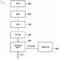
Fig. 4 is a system block diagram showing an example of the fragrance providing apparatus 1 according to the present embodiment. As shown in fig. 4, the battery 400 and the substrate 800 are electrically connected to each other. Then, when the switch 700 is pressed, energization to a driving circuit for driving the air pump 300 mounted on the substrate 800 is performed, and the air pump 300 is driven. Accordingly, the air pump 300 starts blowing air, and the air supplied from the air pump 300 is delivered to the holding passage 210 of the perfume holding member 200. Then, the vaporized components of the perfume held by the holding passage 210 of the perfume holding member 200 are discharged to the outside from the discharge port 110 of the cap 100. Switching of the holding channels 210, into which air is introduced, among the plurality of holding channels 210 of the fragrance holding member 200 by the rotating mechanism 500 is manually performed.
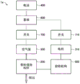
In this specification, as described using fig. 4, the fragrance providing apparatus 1 in which switching of the holding channel 210 into which air is introduced by the channel rotating mechanism 500 is manually performed is mainly described. However, the switching type of the rotation mechanism 500 is not limited to this example, and for example, the rotation mechanism 500 may be driven by a motor. Such a fragrance providing apparatus 1a according to another embodiment includes a motor 310 that drives the rotation mechanism 500, and a switch 710 that switches energization to a drive circuit for driving the motor 310 mounted on the substrate 800. According to the fragrance providing apparatus 1a, for example, as shown in fig. 5, when the switch 710 is pressed, energization to a drive circuit for driving the motor 310 mounted on the substrate 800 is performed, and the motor 310 is driven. Accordingly, the rotation mechanism 500 is driven by the motor 310, and switching of the holding passage 210 into which air is introduced among the plurality of holding passages 210 of the fragrance holding member 200 by the rotation mechanism 500 is performed.
<2. rotating mechanism >
[2-1. first example ]
Now, a rotation mechanism 501 according to a first example will be described with reference to fig. 6 to 8. Fig. 6 and 7 are explanatory views showing an example of the configuration of the perfume holding member 200 and the rotation mechanism 501 according to the first example. Fig. 6 is a sectional view taken along a section through the holding passage 210a to which the air supplied from the air pump 300 is delivered. Fig. 7 is a sectional view taken along a section through the holding passage 210b to which the air supplied from the air pump 300 is not delivered. FIG. 8 is a cross-sectional view of an example of the section B1-B1 shown in FIG. 6. As shown in fig. 6 and 7, the rotation mechanism 501 according to the first example includes a rotation transfer unit 510 and an air introduction unit 520. The rotation mechanism 501 according to the first example is configured such that the rotation of the rotation transmitting unit 510 is transmitted to the perfume holding member 200. In addition, the scent holding member 200 and the rotation transfer unit 510 are rotatable with respect to the air introduction unit 520. Details of such a rotation mechanism 501 are described below.
The air introducing unit 520 has a large diameter portion 522 and a small diameter portion 524 on the rear end side, and the small diameter portion 524 is provided at the center portion on the front end side of the large diameter portion 522 and protrudes toward the front end direction. For example, the large-diameter portion 522 and the small-diameter portion 524 each have a substantially cylindrical shape. The large diameter portion 522 is provided with a flow passage 522a for guiding air supplied from the air pump 300 to the holding channel 210 a. For example, the rear end portion of the flow passage 522a communicates with the front end portion of the flow passage 610 of the cabinet 600 shown in fig. 2. Thereby, the air supplied from the air pump 300 is delivered to the flow path 522a via the flow path 610. The front end portion of the flow path 522a is provided with an introduction port 522b, and the introduction port 522b communicates with the holding channel 210a and guides air supplied from the air pump 300 to the holding channel 210 a. The introduction port 522b may also communicate with the holding channel 210a via another flow passage, and, for example, as shown in fig. 6, communicate with the holding channel 210a via a flow passage 514b provided to the rotation transmitting unit 510.
The rotation transmitting unit 510 includes a cylindrical portion 512 and a bottom portion 514, the cylindrical portion 512 holding an outer peripheral portion of the rear end side of the flavor holding member 200, the bottom portion 514 being provided on an inner peripheral side of the rear end portion of the cylindrical portion 512 and holding the rear end portion of the flavor holding member 200. The flavor retaining member 200 is fitted to the inner peripheral portion of the cylindrical portion 512. Note that the shape of the cylindrical portion 512 is not particularly limited, and may be any shape that fits the fragrance holding member 200. For example, movement of the fragrance holding member 200 in the axial direction relative to the rotation transmission unit 510 is restricted by slightly pressing the fragrance holding member 200 against the cylindrical portion 512. Note that, in order to reliably restrict the movement of the fragrance holding member 200 in the axial direction with respect to the rotation axis, a mechanism that biases the outer peripheral portion of the rotation transmission unit 510 to the inner peripheral portion side may be applied.
The front end of the bottom 514 faces the rear end of the fragrance holding member 200, and the rear end of the bottom 514 faces the step between the large diameter portion 522 and the small diameter portion 524 of the air introduction unit 520. An opening 514a may be provided at the center of the bottom 514, the opening 514a communicating with the inner peripheral portion of the fragrance holding member 200, and the small diameter portion 524 of the air introduction unit 520 may be inserted into the opening 514 and the inside of the inner peripheral portion of the fragrance holding member 200. For example, small diameter portion 524 serves as a guide for facilitating assembly of fragrance holding member 200 and the rotation mechanism. Therefore, the small diameter portion 524 may be omitted from the structure of the rotation mechanism 501. In addition, in the case where the small-diameter portion 524 serves as a guide, the small-diameter portion 524 may have a shape such as a polygonal column or an elliptical cylinder as long as the shape thereof is relatively rotatable with respect to the perfume holding member 200 and the rotation transmitting unit 510. In the bottom portion 514, a flow path 514b is provided to penetrate the bottom portion 514, the flow path 514b communicating with each holding channel 210 of the flavor holding member 200.
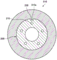
An inner peripheral portion of the cylindrical portion 512 is provided with a locking projection 512a projecting inward. For example, the locking protrusion 512a is provided to extend in the axial direction of the cylindrical portion 512. As shown in fig. 6 and 8, locking projection 512a is fitted into locking groove 230, and locking groove 230 is provided on the outer peripheral portion of fragrance holding member 200 so as to extend in the axial direction of fragrance holding member 200. Accordingly, the rotation of the rotation transmitting unit 510 is transmitted to the perfume holding member 200. Therefore, by rotating the rotation transmitting unit 510, the perfume holding member 200 can be rotated with respect to the introduction port 522 b. It should be noted that the locking groove may be provided on the cylindrical portion 512 side, and the locking projection may be provided on the fragrance holding member 200 side.
The locking protrusion 512a of the cylindrical part 512 and the locking groove 230 of the flavor holding member 200 are one example of a mechanism having a function of transmitting the rotation of the rotation transmitting unit 510 to the flavor holding member 200, and the mechanism for achieving the function is not limited to this example. For example, this function may be achieved by slightly pressing the fragrance holding member 200 to the cylindrical portion 512, in which case the locking protrusions 512a and locking grooves 230 may be omitted from the configuration of the rotation mechanism 501 and fragrance holding member 200. In addition, this functionality may be implemented as follows: the shape of the cross section of the fragrance holding member 200 is set to a shape other than a circle, for example, a polygon or an ellipse, and the shape of a part of the cylindrical portion 512 fitted with the fragrance holding member 200 is set to a shape corresponding to the fragrance holding member 200, thereby preventing relative rotation of the fragrance holding member 200 and the cylindrical portion 512.
The rear end surface of the rotation transmitting unit 510 is provided with an annular projection 518, and the annular projection 518 projects and covers the outer peripheral portion of the front end side of the large diameter portion 522 of the air introducing unit 520. The outer peripheral portion of the large diameter portion 522 on the tip end side is fitted to the inner peripheral portion of the annular projection 518. The annular protrusion 518 serves as a guide for the rotation of the rotation transfer unit 510 with respect to the air introduction unit 520. In addition, a protrusion 518a protruding inward is provided on a part of the inner peripheral portion of the annular protrusion 518, and the protrusion 518a is locked in an annular groove 522f formed along the outer periphery of the large diameter portion 522. Therefore, the fragrance holding member 200 and the rotation transmitting unit 51 can rotate relative to the air introduction unit 520 without the rotation transmitting unit 510 moving in the axial direction relative to the air introduction unit 520.
The rotation axis of the rotation of the fragrance holding member 200 and the rotation transfer unit 510 substantially coincides with the central axis of the fragrance holding member 200, the rotation transfer unit 510, and the air introduction unit 520. Since the fragrance holding member 200, the cylindrical portion 512 of the rotation transmitting unit 510, and the large diameter portion 522 of the air introducing unit 520 have a cylindrical shape or a cylindrical shape whose central axes substantially coincide with each other, the movable range of the member in rotation caused by the rotation mechanism 500 can be made small. However, the shapes of the fragrance holding member 200, the cylindrical portion 512 of the rotation transmitting unit 510, and the large diameter portion 522 of the air introduction unit 520 are not particularly limited.
The guide for rotation of the rotation transmission unit 510 with respect to the air introduction unit 520 may be realized by a small diameter portion 524 of the air introduction unit 520 inserted into the opening 514a of the bottom 514 and inside the inner peripheral portion of the fragrance holding member 200. In this case, the small diameter portion 524 is fitted into the opening 514a of the bottom portion 514 and the inner peripheral portion of the flavor retaining member 200, and the annular protrusion 518 may be omitted from the structure of the rotation mechanism 501.
The rotation mechanism 501 according to the first example makes the rotation transmission unit 510 rotatable with respect to the air introduction unit 520, and is able to rotate the perfume holding member 200 with respect to the air introduction unit 520 provided with the introduction port 522b in such a manner that the holding channel 210 communicating with the introduction port 522b is switched. For example, the plurality of holding passages 210 of the fragrance holding member 200 are provided on the circumference of the rotation axis of the relative rotation of the air introduction unit 520 and the fragrance holding member 200 caused by the rotation mechanism 501. Specifically, the plurality of holding channels 210 of the fragrance holding member 200 are arranged on the circumference of the central axis of the fragrance holding member 200. Here, the perfume holding member 200 rotates around the central axis of the perfume holding member 200. Accordingly, by rotating the perfume holding member 200 with respect to the air introduction unit 520, the holding passage 210 communicating with the introduction port 522b can be switched.
The holding channel 210 can hold different types of fragrances, in which case the fragrance provided by the fragrance providing apparatus 1 can be switched by switching the holding channel 210 in communication with the introduction opening 522 b. It should be noted that the holding channel 210 may be made to hold the same type of fragrance. For example, by using a larger number of holding passages 210 to hold the perfume of which the use frequency is high, the duration of each perfume can be set appropriately according to the use frequency of each perfume.
As described above, according to the fragrance providing apparatus 1 of the present embodiment, the supply of air to the plurality of spaces holding the fragrance can be realized by one air flow source, so that it is possible to suppress an increase in the size of the apparatus due to an increase in the number of air flow sources in the case where the number of spaces is increased. Therefore, the device can be reduced in size.
It should be noted that in the case where the cover 100 is fixed relative to the perfume holding member 200, the cover 100 rotates with the rotation of the perfume holding member 200. In this case, the cover 100 is provided with the same number of discharge ports 110 as the holding passages 210, and each discharge port 110 is provided to communicate with the front end portion of the corresponding holding passage 210. On the other hand, in a case where the cover 100 is fixed with respect to the air introduction unit 520, the perfume holding member 200 rotates with respect to the cover 100. In this case, the cover 100 is provided with one discharge port 110, and the one discharge port 110 communicates with the holding passage 210a communicating with the front end portion of the introduction port 522 b.
In addition, as described above, the fragrance holding member 200 has a cylindrical shape, the central axis of which substantially coincides with the rotational axis of the relative rotation of the air introduction unit 520 and the fragrance holding member 200. Therefore, the movable range of the member in switching of the holding channel 210 communicating with the introduction port 522b can be made small, and therefore the size of the apparatus can be further reduced.
The rotation mechanism 500 includes a positioning mechanism that determines the rotation angle of the relative rotation of the air introduction unit 520 and the fragrance holding member 200 to communicate the introduction port 522b with the holding channel 210. Specifically, the positioning mechanism includes a locking member that locks the air introduction unit 520 or the fragrance holding member 200, and a biasing member that biases the locking member. The steel ball 522c shown in fig. 7 is an example of a locking member that locks the flavor retaining member 200 by the rotation transmitting unit 510, and the spring 522d is an example of a biasing member.
As shown in fig. 6 and 7, a recess 516 is provided in a portion of the rear end surface of the rotation transfer unit 510 that faces the step between the large diameter portion 522 and the small diameter portion 524 of the air introduction unit 520. In addition, the steel ball 522c and the spring 522d are disposed at a step between the large diameter portion 522 and the small diameter portion 524 of the air introduction unit 520. The spring 522d is accommodated in a hole 522e formed at a step between the large-diameter portion 522 and the small-diameter portion 524 and made in the axial direction of the air introduction unit 520, and a steel ball 522c is provided at a front end side of the spring 522 d. For example, as shown in fig. 7, two pairs of springs 522d and steel balls 522c are provided. It should be noted that the number of pairs may be another number greater than or equal to 1. The recesses 516 are provided in the same number as the pairs of the springs 522D and the steel balls 522C for each of the holding channels 210. The arrangement of the recesses 516 is set according to the position of each retaining channel 210 in the fragrance retaining member 200 in the circumferential direction.
Specifically, the arrangement of the concave portion 516 on the rear end surface of the rotation transmission unit 510 is set in the following manner: in a state where the introduction port 522b communicates with the holding passage 210a, one of the recesses 516 is located on the front end side of the steel ball 522. Therefore, with the introduction port 522b communicating with one of the plurality of holding passages 210, the steel ball 522c is pressed to the recess 516 under the bias of the spring 522d, so that the rotation transfer unit 510 is positioned with respect to the air introduction unit 520. Thereby, the switching of the holding passage 210 communicating with the introduction port 522b can be performed more easily.
On the other hand, the arrangement of the concave portion 516 on the rear end surface of the rotation transmission unit 510 is set in the following manner: in the case where the introduction port 522b does not communicate with each of the plurality of holding passages 210, no recess 516 is located on the front end side of the steel ball 522. Therefore, in a case where the introduction port 522b is not communicated with each of the plurality of holding passages 210, the steel ball 522c is accommodated in the hole 522e together with the spring 522 d; accordingly, the rotation of the rotation transfer unit 510 with respect to the air introduction unit 520 may be smoothly performed.
In addition, the direction in which the locking member is biased may be a direction crossing the rotational axis of the relative rotation of the air introduction unit 520 and the fragrance holding member 200. For example, the function of the positioning mechanism described above may be implemented in the following manner: the lock member and the biasing member are provided on the outer peripheral side of the rotation transmitting unit 510, and the lock member is biased in the radial direction of the rotation transmitting unit 510. In this case, for example, the outer peripheral portion of the rotation transmitting unit 510 may be provided with a concave portion.
[2-2. second example ]
The first example has been described in which the rotation mechanism 501 is capable of rotating the perfume holding member 200 relative to the air introduction unit 520 provided with the introduction port 522b, but the configuration of the rotation mechanism 501 is not limited to this example, and the rotation mechanism is capable of rotating the member provided with the introduction port relative to the perfume holding member. Described below with reference to fig. 9 and 10 is a second example in which a rotation mechanism is capable of rotating a member provided with an introduction port relative to a perfume holding member.
Fig. 9 and 10 are explanatory views showing an example of the configuration of the perfume holding member 200 and the rotating mechanism 502 according to the second example. Fig. 9 is an explanatory view in which description of the cover 100a is omitted, and fig. 10 is an explanatory view including description of the cover 100 a. As shown in fig. 9 and 10, the rotation mechanism 502 according to the second example includes an air introduction unit 560, a positioning unit 570, and a housing 580. In the rotation mechanism 502 according to the second example, the air introduction unit 560 is rotatable with respect to the fragrance holding member 200. Details of such a rotation mechanism 502 will be described below.
The air introducing unit 560 includes a large diameter portion 562 on the rear end side and a small diameter portion 564 which is a protruding portion provided at the center portion of the front end side of the large diameter portion 562 and protrudes in the front end direction. For example, the large-diameter portion 562 and the small-diameter portion 564 each have a substantially cylindrical shape. The large diameter portion 522 is provided with a flow passage 562a for guiding air supplied from the air pump 300 to the holding channel 210 a. The rear end portion of the flow passage 562a communicates with a flow passage 572 provided in the positioning unit 570. Further, a rear end portion of flow passage 572 provided in positioning unit 570 communicates with a front end portion of flow passage 610 of casing 600. Accordingly, air supplied from the air pump 300 is delivered to the flow path 562a via the flow path 610 and the flow path 572. The front end portion of the flow path 562a is provided with an introduction port 562b, and the introduction port 562b communicates with the holding channel 210a and introduces air supplied from the air pump 300 to the holding channel 210 a. The introduction port 562b may communicate with the holding channel 210a via another flow path.
Further, a flange 562c protruding in the outer circumferential direction is provided at the rear end of the large diameter portion 562. The cabinet 600 is provided with a recess having a shape corresponding to the flange 562c, and the movement of the air introduction unit 560 to the translational direction is restricted by the flange 562c supported by the recess of the cabinet 600. In addition, the recess may serve as a guide for rotation of the air introduction unit 560 with respect to the cabinet 600. Accordingly, the air introduction unit 560 can rotate with respect to the cabinet 600.
The function as a guide for the rotation of the air introduction unit 560 with respect to the cabinet 600 can be achieved by inserting the small diameter portion 564 of the air introduction unit 560 into the inside of the inner peripheral portion of the fragrance holding member 200. In this case, small diameter portion 564 is fitted to the inner peripheral portion of fragrance holding member 200.
The housing 580 is a member that accommodates other members constituting the fragrance providing device except for a part of the front end side of the fragrance holding member 200, and the casing 600 is fixed inside the housing 580. The rear end portion of the cover 100a is connected to the front end portion of the housing 580. Accordingly, the cover 100a and the housing 580 accommodate other members constituting the fragrance providing apparatus. Here, the cover 100a is configured to be freely rotatable with respect to the housing 580.
In addition, as shown in fig. 9 and 10, an inner peripheral portion of the front end portion of the housing 580 is provided with a locking boss 582 protruding inward. For example, the locking protrusion 582 is arranged to extend along the axial direction of the fragrance holding member 200. The locking projection 582 is fitted with a locking groove 230, and the locking groove 230 is provided on the outer peripheral portion of the fragrance holding member 200 to extend along the axial direction of the fragrance holding member 200. This makes it possible to prevent the fragrance holding member 200 from rotating and to rotate the air introduction unit 560 relative to the fragrance holding member 200 in the case where the air introduction unit 560 is rotated. Accordingly, the introduction port 562b of the air introduction unit 560 can rotate relative to the fragrance holding member 200. Note that a locking groove may be provided on the housing 580 side, and a locking projection may be provided on the fragrance holding member 200 side.
The locking protrusion 582 of the housing 580 and the locking groove 230 of the fragrance holding member 200 are examples of a mechanism having a function of preventing the fragrance holding member 200 from rotating in the case where the air introduction unit 560 is rotated, and the mechanism for achieving the function is not limited to this example. For example, this function may be achieved by slightly pressing the fragrance retaining member 200 against the housing 580, in which case the locking protrusions 582 and locking grooves 230 may be omitted from the configuration of the rotation mechanism 502 and fragrance retaining member 200. Furthermore, this functionality can be implemented in the following way: the shape of the cross section of the fragrance holding member 200 is set to a shape other than a circle, such as a polygon or an ellipse, and the shape of a part of the housing 580 fitted with the fragrance holding member 200 is set to correspond to the shape of the fragrance holding member 200, thereby preventing relative rotation of the fragrance holding member 200 and the housing 580.
The rotation axis of the rotation of the air introduction unit 560 substantially coincides with the central axis of the fragrance holding member 200 and the air introduction unit 560. Since fragrance holding member 200 and small-diameter portion 564 and large-diameter portion 562 of air introduction unit 560 have cylindrical shapes or cylindrical shapes whose central axes substantially coincide with each other, the movable range of the member in rotation caused by rotation mechanism 502 can be made small. However, the shapes of the fragrance holding member 200 and the small-diameter portion 564 and the large-diameter portion 562 of the air introduction unit 560 are not particularly limited.
The rotation mechanism 502 according to the second example makes the air introduction unit 560 rotatable with respect to the fragrance holding member 200, and is able to rotate the air introduction unit 560 with respect to the fragrance holding member 200 in such a manner that the holding passage 21 communicating with the introduction port 562b is switched, the air introduction unit 560 being a member provided with the introduction port 562 b. For example, the plurality of holding channels 210 of the fragrance holding member 200 are provided on the circumference around the rotational axis of the relative rotation of the air introduction unit 560 and the fragrance holding member 200 caused by the rotating mechanism 502. Specifically, the plurality of holding channels 210 of the scent retaining member 200 are disposed on a circumference around the central axis of the scent retaining member 200. Here, the air introduction unit 560 rotates around the central axis of the perfume holding member 200. Thus, by rotating the air introduction unit 560 relative to the fragrance holding member 200, the holding channel 210 communicating with the introduction port 562b can be switched. Therefore, in the case where the holding passage 210 holds different kinds of fragrances, the fragrance provided by the fragrance providing apparatus 1 can be switched. It should be noted that the holding channel 210 may hold the same kind of fragrance.
The positioning unit 570 has a function as a positioning mechanism that determines the rotation angle of the relative rotation of the air introduction unit 560 and the fragrance holding member 200 in such a manner that the introduction port 562b communicates with the holding passage 210. Specifically, the function as the positioning mechanism is achieved by a locking member that locks the air introduction unit 560 or the fragrance holding member 200, and a biasing member that biases the locking member. The steel ball 576 shown in fig. 9 and 10 is an example of a locking member of the locking air introduction unit 560, and the spring 574 is an example of a biasing member.
As shown in fig. 9 and 10, the rear end surface of the air introduction unit 560 is provided with a recess 562 d. Further, a steel ball 576 and a spring 574 are provided on a front end surface of the positioning unit 570. The spring 574 is accommodated in a hole 578, the hole 578 is made in the axial direction of the air introduction unit 560, and a steel ball 576 is provided on the front end side of the spring 574. For example, as shown in fig. 9 and 10, a pair of springs 574 and steel balls 576 are provided. It should be noted that the number of pairs may also be other numbers above 2. The same number of recesses 562d as the number of pairs of springs 574 and steel balls 576 are provided for each retention channel 210. The arrangement of recesses 562d is set according to the position of each holding channel 210 in the circumferential direction in fragrance holding member 200.
Specifically, the configuration of the concave portions 562d on the rear end surface of the air introduction unit 560 may be set in such a manner that one of the concave portions 562d is located on the front end side of the steel ball 576 in a state where the introduction port 562b communicates with the holding passage 210 a. Therefore, with the introduction port 562b communicating with one of the plurality of holding passages 210, the steel ball 576 is pressed against the recess 562d by the biasing force of the spring 574, so that the air introduction unit 560 is positioned with respect to the positioning unit 570. Here, the positioning unit 570 is fixed with respect to the cabinet 600. Further, the fragrance holding member 200 is fixed to the casing 600 via the housing 580. Accordingly, the air introduction unit 560 is positioned with respect to the perfume holding member 200 by the function of the positioning unit 570 as a positioning mechanism. Therefore, switching of the holding passage 210 communicating with the introduction port 562b can be performed more easily.
On the other hand, the configuration of the recess 562d on the rear end surface of the air introducing unit 560 is set in the following manner: in a state where the introduction port 562b is not communicated with each of the plurality of holding passages 210, no recess 562d is located on the front end side of the steel ball 576. Thus, with intake 562b not communicating with each of the plurality of holding channels 210, steel ball 576 is received in bore 578 along with spring 574; accordingly, the rotation of the air introduction unit 560 with respect to the positioning unit 570 and the perfume holding member 200 can be smoothly performed.
In addition, the direction in which the locking member is biased may be a direction crossing the rotational axis of the relative rotation of the air introduction unit 560 and the fragrance holding member 200. For example, the function of the positioning mechanism described above may be implemented in the following manner: the locking member and the biasing member are provided on the outer circumferential side of the air introduction unit 560, and the locking member is biased in the radial direction of the air introduction unit 560. In this case, for example, a concave portion may be provided at the outer peripheral portion of the air introduction unit 560.
In addition, the positioning unit 570 is provided with a flow passage 572, a rear end portion of the flow passage 572 communicates with a front end portion of the flow passage 610 of the casing 600, and a front end portion of the flow passage 572 communicates with the flow passage 562a of the air introducing unit 560. Air supplied from the air pump 300 is delivered from the flow path 610 of the housing 600 to the flow path 562a of the air introduction unit 560 via the flow path 572 of the positioning unit 570.
<3. modified example >
Now, a fragrance providing apparatus according to a modified example that facilitates identification of which of a plurality of fragrances is selected as the fragrance corresponding to the fragrance provided by the fragrance providing apparatus will be described with reference to fig. 11 to 14.
First, a first modified example is explained with reference to fig. 11 to 13. In the first modified example, as the rotation mechanism, the rotation mechanism 501 according to the above-described first example is applied, which is capable of rotating the perfume holding member relative to the member provided with the introduction port. Fig. 11 is an explanatory diagram showing an example of the configuration of the tag 260 according to the first modified example. In the first modified example, on the outer peripheral surface of the fragrance holding member 200, the kinds of various fragrances held by the plurality of holding channels 210 are indicated. For example, as shown in fig. 11, a label 260 indicating the kind of perfume held by the holding channel 210 is provided on the outer circumferential surface of the perfume holding member 200. The label 260 records the type of perfume held by the corresponding holding channel 210 at a position of the perfume holding member 200 that substantially coincides with the circumferential position where each holding channel 210 is provided.
Fig. 12 and 13 are explanatory views showing an example of the configuration of the fragrance holding member 200, the cover 100b, and the rotation mechanism 501 according to the first modification example. Fig. 12 shows a state before the perfume holding member 200 is covered with the cover 100b, and fig. 13 shows a state after the perfume holding member 200 is covered with the cover 100 b. The outer peripheral portion of the cover 100b according to the first modification is provided with an opening 130. The cover 100b is an example of a cover member according to the present invention. As shown in fig. 13, the position and size of the opening 130 in the cover 100b are set in the following manner: in a state after the fragrance holding member is covered with the cover 100b, the type of fragrance described on the label 260 can be seen from the outside through the opening 130. The shape of the outer shape of the cover 100b may be, but is not particularly limited to, a rectangular parallelepiped as shown in fig. 12 and 13.
In the first modified example, the rotation mechanism 501 is capable of relatively rotating the cap 100b and the flavor holding member 200. Specifically, in the first modified example, the rotation mechanism 501 is capable of rotating the perfume holding member 200 relative to the cover 100 b. On the outer peripheral surface of the perfume holding member 200, the kind of perfume held in the holding passage 210 communicating with the introduction port 522b is indicated at a position facing the opening 130. Thereby, the kind of the perfume held in the holding passage 210 communicating with the introduction port 522b can be seen through the opening 130, which helps to identify which of the plurality of perfumes is selected as the perfume corresponding to the perfume provided by the perfume providing device. Note that, in the first modified example, the rotation mechanism 502 according to the above-described second example may also be applied as the rotation mechanism.
Now, a second modified example in which the rotation mechanism 502 according to the above-described second example is applied as a rotation mechanism, the rotation mechanism 502 being capable of rotating the member having the introduction port relative to the fragrance holding member will be described with reference to fig. 14.
Fig. 14 is an explanatory diagram showing an example of the configuration of the fragrance providing apparatus 1b of the second modified example. In the fragrance providing apparatus 1b according to the second modified example, unlike the cover 100a according to the second example described above, the outer peripheral portion of the cover 100c is provided with the opening 130. In a second modified example, the rotation mechanism 502 is capable of rotating the cap 100c relative to the perfume holding member 200. In addition, in the second modified example, as in the first modified example, on the outer peripheral surface of the perfume holding member 200, the kind of perfume held in the holding passage 210 in communication with the introduction port 562b is indicated at a position facing the opening 130. Therefore, according to the second modified example, the same effects as those of the first modified example can be obtained. Note that, as shown in fig. 14, the outer circumferential portion of the housing 580 may be provided with a button 584 for pressing the switch 700. The switch 700 is configured to be pressed by pressing the button 584.
<4. conclusion >
As described above, according to the embodiment of the present invention, the rotation mechanism 500 can relatively rotate the flavor holding member 200 and the member provided with the introduction port, which communicates with the holding channel of the part of the plurality of holding channels 210 and introduces the air supplied from the air pump 300 to the holding channel 210 of the part, in such a manner that the part of the holding channel 210 communicating with the introduction port is switched. Thus, the supply of air to the plurality of spaces each containing fragrance may be achieved by one air flow source. This can suppress an increase in the size of the apparatus caused by an increase in the number of air flow sources with an increase in the number of spaces. Therefore, the size of the device can be reduced.
The above explains the example in which one holding channel 210 of the plurality of holding channels 210 communicates with the introduction port that introduces the air supplied from the air pump 300 to the holding channel 21; however, the scope of protection of the invention is not limited to this example. For example, the introduction port may communicate with two or more holding channels 210 at the same time.
The above describes an example in which the rear end portion of the holding channel 210 communicates with the introduction port provided on the rear end face of the fragrance holding member 200; however, the scope of protection of the invention is not limited to this example. For example, the rear end of the holding channel 210 may be formed on the outer circumferential surface of the fragrance holding member 200. In this case, the air flow path between the air pump 300 and the holding channel 210 is set to correspond to the configuration of the rear end portion of the holding channel 210.
The above describes an example in which the front end portion of the holding passage 210 communicates with the discharge port 110 of the cover 100 provided on the front end face of the fragrance holding member 200; however, the scope of protection of the invention is not limited to this example. For example, the front end of the holding channel 210 may be formed on the outer circumferential surface of the fragrance holding member 200. In this case, the configuration of the discharge port 110 of the cover 100 is set to correspond to the configuration of the front end portion of the holding channel 210.
The preferred embodiment(s) of the present invention has been described above with reference to the accompanying drawings, but the present invention is not limited to the above examples. Those skilled in the art will envision many variations and modifications within the scope of the claims appended hereto, and it is understood that such variations and modifications naturally fall within the scope of the present invention.
Further, the effects described in the present specification are merely illustrative or exemplary effects, and are not restrictive. That is, the technology according to the present invention can achieve other effects that are obvious to those skilled in the art from the description of the present specification, in addition to or instead of the above-described effects.
In addition, the present invention may also be configured as follows.
(1) A scent-providing apparatus comprising:
a fragrance holding member in which a plurality of holding passages each holding a fragrance are provided to penetrate the fragrance holding member; and
a rotation mechanism capable of relatively rotating the fragrance holding member and a member provided with an introduction port communicating with the holding passage of the one portion of the plurality of holding passages and introducing air supplied from the air flow source to the holding passage of the one portion, thereby switching the holding passage of the one portion communicating with the introduction port.
(2) The fragrance providing apparatus according to (1), wherein the plurality of holding passages are provided on a circumference around a rotation axis which is a rotation axis of relative rotation of the member provided with the introduction port and the fragrance holding member.
(3) The fragrance providing apparatus according to (1) or (2), wherein the fragrance holding member has a cylindrical shape whose central axis substantially coincides with a rotation axis which is a rotation axis of relative rotation of the member provided with the introduction port and the fragrance holding member.
(4) The fragrance providing apparatus according to any one of (1) to (3), wherein the rotation mechanism is capable of rotating the fragrance holding member relative to the member provided with the introduction port.
(5) The fragrance providing apparatus according to (4), wherein the rotation mechanism includes a rotation transmitting unit that holds the fragrance holding member and a mechanism that transmits rotation of the rotation transmitting unit to the fragrance holding member, and the rotation mechanism is capable of rotating the fragrance holding member and the rotation transmitting unit relative to the member provided with the introduction port.
(6) The fragrance providing apparatus according to any one of (1) to (3), wherein the rotating mechanism is capable of rotating the member provided with the introduction port relative to the fragrance holding member.
(7) The fragrance providing apparatus according to (6), wherein,
the member provided with the introduction port includes a projection penetrating the fragrance holding member, and
the front end of the protruding part is provided with a recessed part, and a protrusion is inserted into the recessed part and positioned on a cover for separating the perfume holding member from the outside.
(8) The fragrance providing apparatus according to any one of (1) to (7), wherein the rotating mechanism includes a positioning mechanism that determines a rotation angle of relative rotation of the member provided with the introduction port and the fragrance holding member in such a manner that the introduction port communicates with the part of the holding passage.
(9) The scent-providing apparatus according to (8), wherein the positioning mechanism includes a locking member that locks the member provided with the introduction opening or the perfume holding member, and a biasing member that biases the locking member.
(10) The scent-providing device according to any one of (1) to (9), comprising,
a cover member that covers the fragrance holding member and is provided with an opening at an outer peripheral portion thereof, wherein
The rotation mechanism is capable of relatively rotating the cover member and the fragrance holding member, and
on the outer peripheral surface of the perfume holding member, a kind of perfume held by the holding passage of the portion communicating with the introduction port is indicated at a position facing the opening.
Reference numerals
1. 1a, 1b fragrance providing device
100. 100a, 100b, 100c cover
110 discharge port
120 of protrusion
130 opening
200 spice holding member
210. 210a, 210b hold channels
230 locking groove
260 label
300 air pump
310 electric machine
400 cell
500. 501, 502 rotation mechanism
510 rotation transmission unit
512 cylindrical part
512a locking projection
514 bottom
514A opening
514b flow path
518 annular projection
518a projection
520 air introduction unit
522 large diameter part
522a flow path
522b introduction port
522c steel ball
522d spring
522e hole
522f annular groove
524 minor diameter portion
560 air introduction unit
562 large diameter part
562a flow path
562b introduction port
562c Flange
564 small diameter part
564a is recessed
570 positioning unit
572 flow channel
574 spring
576 steel ball
578 hole
580 casing
582 locking projection
584 push-button
600 casing
610 flow path
700. 710 switch
800 substrate
Claims (16)
1. A scent-providing apparatus comprising:
a fragrance holding member having a hollow cylindrical shape and provided therein with a plurality of holding passages each holding a fragrance to penetrate the fragrance holding member;
a member provided with an introduction port that communicates with and introduces air supplied from an airflow source to a part of the plurality of holding passages;
a rotation mechanism capable of relatively rotating the perfume holding member and the member provided with the introduction port, thereby switching the holding passage of the part communicating with the introduction port; and
a cover member that separates the fragrance holding member from the outside and is provided with a discharge port that communicates with a front end portion of the partial holding passage, wherein
The member provided with the introduction port is inserted into the inside of the hollow inner peripheral portion of the fragrance holding member to engage with the lid member,
the fragrance holding member, the member provided with the introduction port, and the rotating mechanism have center axes coincident with each other, and
the rotation mechanism is capable of rotating the perfume holding member relative to the cover member and the member provided with the introduction port.
2. The scent-providing apparatus according to claim 1, wherein the plurality of holding channels are provided on a circumference around a rotation axis which is a rotation axis of relative rotation of the member provided with the introduction port and the fragrance holding member.
3. The fragrance providing apparatus according to claim 1, wherein the rotation mechanism has a rotation transmitting unit that holds the fragrance holding member and a mechanism that transmits rotation of the rotation transmitting unit to the fragrance holding member, and the rotation mechanism is capable of rotating the fragrance holding member and the rotation transmitting unit relative to the member provided with the introduction port.
4. The scent-providing apparatus according to claim 1, wherein,
the member provided with the introduction port includes a projection penetrating the fragrance holding member, and
the front end of the protruding portion is provided with a recessed portion into which a protrusion is inserted, and the protrusion is provided on the cover member.
5. The scent-providing apparatus according to claim 1, wherein the rotating mechanism includes a positioning mechanism that determines a rotation angle of relative rotation of the member provided with the introduction port and the perfume holding member in such a manner that the introduction port communicates with the part of the holding passage.
6. The scent-providing device according to claim 5, wherein the positioning mechanism includes a locking member that locks the member provided with the introduction opening or the fragrance holding member, and a biasing member that biases the locking member.
7. The scent-providing apparatus according to claim 1, wherein,
the cover member covers the fragrance holding member,
an opening is provided in an outer peripheral portion of the cover member,
the rotation mechanism is capable of relatively rotating the cover member and the fragrance holding member, and
on the outer peripheral surface of the perfume holding member, a kind of perfume held by the holding passage of the portion communicating with the introduction port is shown at a position facing the opening.
8. The scent-providing apparatus according to claim 1, wherein,
the cover member is provided with a protrusion protruding toward the fragrance holding member side,
the member provided with the introduction port includes a protruding portion that is inserted into an inner side of an inner peripheral portion of the fragrance holding member and extends in an axial direction of the fragrance holding member, and
the projection provided on the cover member is engaged with a front end portion of the protruding portion.
9. The scent-providing apparatus according to claim 1, wherein the scent is held in a state of being adhered to an inner surface of the holding channel.
10. The scent-providing device according to claim 9, wherein the air flows from a rear end side to a front end side of the holding channel.
11. The scent-providing apparatus according to claim 1, further comprising:
a receiving member that receives at least a portion of the fragrance retaining member,
wherein an outer peripheral portion of the fragrance holding member is provided with a locking projection or a locking groove which prevents relative rotation of the fragrance holding member and the accommodation member by being engaged with an inner peripheral portion of the accommodation member.
12. The scent-providing apparatus according to claim 6, further comprising:
a plurality of recesses provided for the plurality of retention channels, wherein,
the rotation angle is fixed by pressing the locking member to the recess by the biasing member, and
the arrangement of the recesses is set in accordance with the position of each of the plurality of holding channels in the circumferential direction in the fragrance holding member.
13. The scent-providing apparatus according to claim 1, further comprising:
the source of the air flow is,
wherein the airflow source is an air pump that includes a diaphragm and performs air blowing by deforming the diaphragm.
14. A body of a scent-providing apparatus, comprising:
a member provided with an introduction port that communicates with and introduces air supplied from an airflow source into a holding passage of a portion of fragrance holding members that have a hollow cylindrical shape and that include fragrance held by a plurality of holding passages penetrating the fragrance holding members; and
a rotation mechanism capable of relatively rotating the perfume holding member and the member provided with the introduction port so as to switch the holding passage of the part communicating with the introduction port, wherein
The member provided with the introduction port is inserted into the inside of the hollow inner peripheral portion of the fragrance holding member to engage with a cover member that separates the fragrance holding member from the outside and is provided with a discharge port communicating with the front end portion of the part of the holding passage,
the fragrance holding member, the member provided with the introduction port, and the rotating mechanism have center axes coincident with each other, and
the rotation mechanism is capable of rotating the perfume holding member relative to the cover member and the member provided with the introduction port.
15. The main body of the scent-providing apparatus according to claim 14, wherein,
the member provided with the introduction port includes a protruding portion that is inserted into an inner side of an inner peripheral portion of the fragrance holding member and extends in an axial direction of the fragrance holding member, and
a projection provided on the cover member to project toward the fragrance holding member side is engaged with a front end portion of the projection.
16. The body of the scent-providing apparatus according to claim 14, further comprising:
a receiving member that receives at least a portion of the fragrance retaining member.
Applications Claiming Priority (3)
| Application Number | Priority Date | Filing Date | Title |
|---|---|---|---|
| JP2015208660A JP6728629B2 (en) | 2015-10-23 | 2015-10-23 | Scent providing device |
| JP2015-208660 | 2015-10-23 | ||
| PCT/JP2016/071755 WO2017068829A1 (en) | 2015-10-23 | 2016-07-25 | Odor presentation device |
Publications (2)
| Publication Number | Publication Date |
|---|---|
| CN108348630A CN108348630A (en) | 2018-07-31 |
| CN108348630B true CN108348630B (en) | 2021-10-08 |
Family
ID=58556919
Family Applications (1)
| Application Number | Title | Priority Date | Filing Date |
|---|---|---|---|
| CN201680060530.2A Active CN108348630B (en) | 2015-10-23 | 2016-07-25 | Fragrance providing device |
Country Status (5)
| Country | Link |
|---|---|
| US (1) | US10994043B2 (en) |
| EP (1) | EP3366316A4 (en) |
| JP (1) | JP6728629B2 (en) |
| CN (1) | CN108348630B (en) |
| WO (1) | WO2017068829A1 (en) |
Families Citing this family (6)
| Publication number | Priority date | Publication date | Assignee | Title |
|---|---|---|---|---|
| US11559599B2 (en) | 2017-09-15 | 2023-01-24 | Sony Corporation | Scent retaining structure, method of manufacturing the scent retaining structure, and scent providing device |
| US11642431B2 (en) | 2017-12-08 | 2023-05-09 | Sony Corporation | Information processing apparatus, control method of the same, and recording medium |
| JP7446731B2 (en) | 2018-08-24 | 2024-03-11 | キヤノン株式会社 | Structure having a flow path and method for manufacturing the same |
| WO2020039860A1 (en) * | 2018-08-24 | 2020-02-27 | キヤノン株式会社 | Structure having flow channel, and method for manufacturing same |
| CN109731203B (en) * | 2018-12-12 | 2022-10-04 | 浦易(上海)生物技术股份有限公司 | Hand-held scent releasing device |
| DE102020210313A1 (en) * | 2020-08-13 | 2022-02-17 | Mahle International Gmbh | Scent container of a scenting device |
Citations (4)
| Publication number | Priority date | Publication date | Assignee | Title |
|---|---|---|---|---|
| TW323231B (en) * | 1995-03-16 | 1997-12-21 | Minnesota Mining & Mfg | |
| CN102245413A (en) * | 2008-10-14 | 2011-11-16 | 汉拏空调株式会社 | Air freshener generator for vehicle air conditioning apparatus |
| CN203089984U (en) * | 2012-12-20 | 2013-07-31 | 上海工商信息学校 | Indoor air freshener separation box |
| CN204395064U (en) * | 2013-11-20 | 2015-06-17 | 马勒贝洱两合公司 | For the fragrance system of motor vehicles |
Family Cites Families (12)
| Publication number | Priority date | Publication date | Assignee | Title |
|---|---|---|---|---|
| JPS481988U (en) * | 1971-05-25 | 1973-01-11 | ||
| JPS63100048U (en) * | 1986-12-17 | 1988-06-29 | ||
| JPH0761355B2 (en) * | 1990-02-09 | 1995-07-05 | ダイキン工業株式会社 | Aroma control device |
| JPH04208161A (en) * | 1990-11-30 | 1992-07-29 | Aichi Kasei Kogyo:Yugen | Fragrance generator |
| JPH04128750U (en) * | 1991-05-20 | 1992-11-25 | 美喜雄 椛木 | scent generator |
| JP2549242Y2 (en) * | 1991-07-19 | 1997-09-30 | 高砂香料工業 株式会社 | Rotary fragrance device |
| JPH0556017U (en) * | 1991-12-26 | 1993-07-27 | ウェン‐チュン、パイ | An aroma machine that can select a fragrance at a fixed time |
| JPH0582442U (en) * | 1992-04-07 | 1993-11-09 | 株式会社日立製作所 | Fragrance cartridge |
| JP2002065832A (en) * | 2000-09-01 | 2002-03-05 | Akira Takagi | Aromatizing device |
| US8850057B2 (en) | 2007-09-20 | 2014-09-30 | Intel Corporation | Healthcare semantic interoperability platform |
| JP2013094436A (en) * | 2011-11-01 | 2013-05-20 | Toppan Printing Co Ltd | Aroma providing device |
| JP5093543B1 (en) | 2012-02-15 | 2012-12-12 | 独立行政法人情報通信研究機構 | Olfactory display |
-
2015
- 2015-10-23 JP JP2015208660A patent/JP6728629B2/en active Active
-
2016
- 2016-07-25 WO PCT/JP2016/071755 patent/WO2017068829A1/en active Application Filing
- 2016-07-25 EP EP16857147.9A patent/EP3366316A4/en active Pending
- 2016-07-25 CN CN201680060530.2A patent/CN108348630B/en active Active
- 2016-07-25 US US15/768,703 patent/US10994043B2/en active Active
Patent Citations (4)
| Publication number | Priority date | Publication date | Assignee | Title |
|---|---|---|---|---|
| TW323231B (en) * | 1995-03-16 | 1997-12-21 | Minnesota Mining & Mfg | |
| CN102245413A (en) * | 2008-10-14 | 2011-11-16 | 汉拏空调株式会社 | Air freshener generator for vehicle air conditioning apparatus |
| CN203089984U (en) * | 2012-12-20 | 2013-07-31 | 上海工商信息学校 | Indoor air freshener separation box |
| CN204395064U (en) * | 2013-11-20 | 2015-06-17 | 马勒贝洱两合公司 | For the fragrance system of motor vehicles |
Also Published As
| Publication number | Publication date |
|---|---|
| CN108348630A (en) | 2018-07-31 |
| US10994043B2 (en) | 2021-05-04 |
| WO2017068829A1 (en) | 2017-04-27 |
| JP2017079839A (en) | 2017-05-18 |
| EP3366316A4 (en) | 2018-11-14 |
| JP6728629B2 (en) | 2020-07-22 |
| US20180303964A1 (en) | 2018-10-25 |
| EP3366316A1 (en) | 2018-08-29 |
Similar Documents
| Publication | Publication Date | Title |
|---|---|---|
| CN108348630B (en) | Fragrance providing device | |
| EP3383207B1 (en) | Reservoir assembly for a personal vaporizer device | |
| US6631888B1 (en) | Battery operated fragrance dispenser | |
| US20230149952A1 (en) | Spray bottle assembly for use with an atomized-spray dispensing device | |
| US7960183B2 (en) | Biochip manufacturing method and biochip manufacturing device | |
| US20200023393A1 (en) | Micro pump vessel | |
| KR20200004516A (en) | Fragrance discharge apparatus | |
| US20210031342A1 (en) | Rotary impact tool | |
| KR20150037468A (en) | Two-component mixing container including piston using spring engagement | |
| EP3232427B1 (en) | Rotation switching device | |
| US20210353816A1 (en) | Aroma diffusing device and method of controlling aroma diffusing device | |
| CN113507863A (en) | Fragrance providing device | |
| CN111166923B (en) | Fragrance box and fragrance display | |
| ZA200608280B (en) | Liquid dispensing device | |
| US20230067572A1 (en) | Aerosol-generating device | |
| JP2021058427A (en) | Scent display | |
| US11285235B2 (en) | Aroma display | |
| US11246997B2 (en) | Handheld filament extension atomizer for precision delivery of drugs and therapeutics | |
| JP6355786B1 (en) | Self-powered ion air gun | |
| ES2371146T3 (en) | PROCEDURE TO PRODUCE A LIQUID CONTAINER. | |
| KR100796308B1 (en) | Electrostatic spraying device | |
| US20230076280A1 (en) | Aerosol-generating device | |
| CN217938761U (en) | Change-over switch and atomizing device | |
| CN113507854B (en) | Aerosol delivery device and aerosol generating device having an aerosol delivery device | |
| KR100765492B1 (en) | Electrostatic spraying device |
Legal Events
| Date | Code | Title | Description |
|---|---|---|---|
| PB01 | Publication | ||
| PB01 | Publication | ||
| SE01 | Entry into force of request for substantive examination | ||
| SE01 | Entry into force of request for substantive examination | ||
| GR01 | Patent grant | ||
| GR01 | Patent grant |