All infrared sensors as shown in Figure 6 are a kind of known sensors, and Fig. 6 only shows the structure of its housing.This infrared sensor 20 has a tabular Infrared filter 21, one metal shells 23, and this housing has one and is used for making described Infrared filter 21 and exterior and the window of sensing element (not shown) is set within it.
This Infrared filter 21 within it the surface and outside surface on all have an insulation course (not shown).This Infrared filter 21 is arranged in the ladder part 24 of housing 23, and described step portion is round described window and outwards projection, and described Infrared filter is fixed by using conductive adhesive 25.
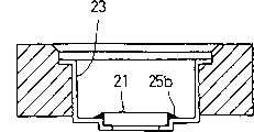
Usually, the described infrared sensing 20 with this structure utilizes following method and makes.At first, shown in Fig. 7 (a), be prepared in advance a kind ofly be formed with a through hole 26 in it, be used for housing 23 be fixed into the state of facing down, make the bracket 27 that sensor is used, a kind of conductive adhesive 25a with thermosetting performance is applied on the inside surface of step portion 24 of described housing 23, described housing 23 is arranged within the bracket 27 that this manufacturing sensor uses.The purpose that applies this conductive adhesive 25a is to flow out from described window 22 for the conductive adhesive 25b that is electrically connected as conductivity that prevents from also will apply afterwards.Much less, it also is no problem using a kind of insulating adhesive to replace conductive adhesive 25a.
Next, shown in Fig. 7 (b), described Infrared filter 21 is placed in the step portion 24 of housing 23, with after coagulation (sclerosis) conductive adhesive 25a.After this, shown in Fig. 7 (c), the conductive adhesive 25b that will have a thermosetting performance is applied between the inside surface of the end face of Infrared filter 21 and housing 23 and is solidified.The result is, links together to described Infrared filter 21 and housing 23 mat conductive adhesive 25b and electric each other property, and the described infrared sensor 20 that takes out from the through hole 26 of making the bracket 27 that sensor uses has primary structure as shown in Figure 6.
But, above-mentioned traditional infrared sensor 20 and manufacture method have been brought some following problems, that is to say, the material cost of Infrared filter 21 is than higher, but this Infrared filter 21 can not done so greatly, it why do to such an extent that be so greatly because when adopting above-mentioned tradition to be provided with because Infrared filter is designed to step portion 24 supportings by shell, and described step portion is centered around the periphery of described window 22, in fact, the shape and size of Infrared filter are just enough corresponding to the window 22 of housing 23.
But, therefore increased the material cost of Infrared filter 21 because the essential window 22 around housing 23 of traditional structure forms step portion 24.In addition, owing to around the window 22 of housing 23, form step portion 24, so the also corresponding increase of the processing cost of housing 23.When being fixed on Infrared filter 21 in the housing 23, apply respectively again and solidify conductive adhesive 25a and 25b to prevent to overflow and obtain the conductivity performance, that is, be necessary to apply at twice cementing agent and solidify, thereby increased procedure of processing.
People imagined a kind of to avoid the problems referred to above, have an infrared sensor 30 of primary structure as shown in Figure 8.That is to say that this infrared sensor 30 has an Infrared filter 31 and and holds the housing 33 of stating Infrared filter 31 to some extent and being formed with a window 32 in it.This Infrared filter 31 has one and is formed on step portion 34 on its end face and mat and uses a kind of conductive adhesive and be fixed on the window frame of described window 32.But, if adopt this set, because the formation of step portion 34, increased the size of described Infrared filter 31 itself, equally also increased the cost of the used material of infrared filter.
The present invention proposes on the basis of these problems considering just, a purpose of the present invention is to provide a kind of infrared sensor, a kind of bracket that uses and a kind of manufacture method of infrared sensor in the process of making sensor, they can be simplified the structure of Infrared filter and housing and can simplify the manufacturing process of infrared sensor.
Infrared sensor of the present invention comprises that a tabular Infrared filter and has a window in it, is used for holding the housing of Infrared filter, its characteristics are, the outside surface that is contained in the described Infrared filter in the described window is arranged to flush each other with the outside surface of housing, and the end face mat conductive adhesive of described Infrared filter and being fixed on the window frame of described window.
The bracket that a kind of manufacturing sensor of the present invention that uses in the process of making above-mentioned infrared sensor is used, described manufacturing sensor comprises a bracket bottom surface with bracket, the outside surface of described Infrared filter and housing abuts one another the state that becomes to flush on described bracket bottom surface, and a groove is formed on the described bracket bottom surface, the residing position of described groove is corresponding with the end face of putting toward each other of described Infrared filter and described window, the spacing that the width of described groove separates each other greater than these end faces.Described groove preferably communicates with ambient atmosphere.
It comprises a kind of method of making infrared sensor of the present invention: the outside surface of housing is abutted against make on the bracket bottom surface of the bracket that sensor uses and the end face of window is placed on the top of groove; The Infrared filter of packing into, make an outside surface of described Infrared filter abut against on the described bracket bottom surface and make an end face of described Infrared filter also be placed on described groove top: so far a kind of conductive adhesive is applied between the described window frame of the described end face of described Infrared filter and described window: last, solidify described conductive adhesive by the electric conduction of heating cementing agent.
For the present invention is described, shown in the drawingsly think preferred embodiment at present, still, should be understood that, that these embodiment are non-limiting and schematic.
Below in conjunction with accompanying drawing one embodiment of the invention are described.
Fig. 1 is the sectional block diagram of the infrared sensor of an expression one embodiment of the invention, and this figure only shows the structure of the major part of described infrared sensor.The described infrared sensor of number in the figure 1 expression.Fig. 2 be one relevant with present embodiment in making the sensor process sectional block diagram of employed bracket, Fig. 3 (a) is respectively the stereographic map of the bracket base plate that changes to some extent to Fig. 3 (c), Fig. 4 (a) is the procedure of processing cut-open view of the manufacture method of the expression described infrared sensor relevant with the embodiment of the invention with Fig. 4 (b), Fig. 5 also is the procedure of processing cut-open view of manufacture method, has wherein used the employed bracket in making the sensor process of another kind of structure.
The infrared sensor 1 of expression one embodiment of the invention comprises that one can be by ultrared tabular Infrared filter 2.Described infrared sensor 1 comprises that also one has the housing 4 of a window that planar is rectangle 3, and described Infrared filter 2 can be fixed within it.Thereby be arranged on a substrate 7 upper sensor elements 6 and be set at the infrared ray that to accept to pass Infrared filter 2 in the described housing 4.An outside surface that is arranged on the Infrared filter 2 in the window 3 flushes with an outside surface of housing 4.The end face of Infrared filter 2 is fixed on the window frame of window 3 by using a kind of conductive adhesive 5.Infrared filter 2 and housing 4 mats utilize its surface tension to infiltrate the conductive adhesive 5 in the gap S1 between two opposed end faces of Infrared filter 2 and window 3 and form mutually and be electrically connected (referring to Fig. 4 (a)).This Infrared filter 2 resembles has an insulation course (not shown) that is formed on its inside surface and the outside surface the Infrared filter of prior art.
This Infrared filter 2 has a kind of simple flat plate shape shape, and window 3 is big or small corresponding on described shape and the housing 4, and not as Infrared filter shown in Figure 8 31, that is, Infrared filter 31 of the present invention does not have step portion on its end face.In situation of the present invention, have only window 3 to be formed on the described housing 4 and do not have step portion 24 shown in Fig. 6.Therefore, the infrared sensor 1 of present embodiment has and more simple Infrared filter 2 of traditional infrared sensor structure compared and housing 4.
When making infrared sensor 1, in manufacture process, need to use one to make the bracket 10 that sensor is used.The bracket 10 that the manufacturing sensor is used has a pair of upper and lower supporting plate 11 and 12, shown in Fig. 2.On described mounting plate 11, be formed with a through hole 13, this through hole has suitable shape and is used for holding described housing 4, and on a surface of the bottom plate 12 of described formation bracket bottom surface, be formed with a groove 14, this groove has the predetermined degree of depth, and having a frame-shaped structure, bottom plate 12 is used for sealing the under shed of through hole 13.Use in the bracket 10 in making the process of sensor this, be formed with window 3 on it and the outside surface that is placed on the outside surface of the housing 4 in the through hole 13 of mounting plate 11 and is placed on the Infrared filter 2 in the window 3 forms and abuts one another and flush mutually on the bracket bottom surface.
The position that is formed on the groove 14 on the bracket bottom surface is corresponding with the opposed end face of Infrared filter 2 and window 3.Groove 14 has a width greater than gap S1 (Fig. 4 (a)), and therefore, these opposed end faces are spaced from each other by gap S1.Much less, groove 14 there is no need to have said structure, that is, a kind of like this structure, wherein its upper shed is sealed by Infrared filter 2 and housing 4 on its whole circumference length.Though groove 14 shown in Figure 2 is shapes of being arranged to a closed-loop,, described groove 14 also can communicate with outside air, for example, shown in Fig. 3 (a), Fig. 3 (b) or Fig. 3 (c).That is to say that in the structure shown in Fig. 3 (a) and Fig. 3 (b), the passage that described groove 14 extends through from four or two angles between the outer face of upper and lower supporting plate 11 and 12 is communicated with outside air.In the structure shown in Fig. 3 (c), a plurality of minor diameter through holes 15 that pass bottom plate 12, extend at its thickness direction open wide on the bottom surface of described groove 14.By all through holes 15, described groove 14 is connected with outside air.
Below in conjunction with Fig. 4, the manufacture method of the infrared sensor 1 of present embodiment is described.
At first, shown in Fig. 4 (a), be prepared in advance and stack and the bracket 10 that in making the process of sensor, uses that constitutes by upper and lower supporting plate 11 and 12, and by housing 4 being inserted in the through hole 13 that constitutes the mounting plate 11 of making the bracket 10 that sensors use, make sensor with in the bracket 10 and housing 4 is contained in.At this moment, the outside surface of housing 4 abuts against on the bracket bottom surface, that is, on the surface of bottom plate 12, and the end face of window 3 is set at groove 14 tops.Next, Infrared filter 2 is contained in the window 3 of housing 4, the outside surface of Infrared filter 2 abuts against on the bracket bottom surface, and the end face of Infrared filter 2 then is arranged on the top of described groove 14.
Then, shown in Fig. 4 (b), by using a kind of well-known cementing agent feed device (not shown) or other analog, conductive adhesive 5 is applied between the described window frame of the end face of Infrared filter 2 and window 3, and adds thermocoagulation subsequently.This moment, the electric cementing agent 5 that applies was at the gap S1 that infiltrates under the effect of surface tension effect between the end face of Infrared filter 2 and window 3, and was frozen into the state that remains in the S1 of gap.Therefore, constitute the Infrared filter 2 of infrared sensor 1 and housing 4 mat conductive adhesives 5 and form mutually and be electrically connected, have as shown in Figure 1 major part structure with the infrared sensor 1 of taking-up the bracket 10 from making sensor.
If the bracket 10 that the manufacturing sensor is used has structure as shown in Figure 2, then be a kind of like this state, i.e. the upper shed of groove 14 is sealed by Infrared filter 2 and housing 4.In this case, be heated and expand owing to being present in air in the groove 14, thereby therefore might make the bond effect step-down of conductive adhesive 5 make the state that is in alignment with each other of Infrared filter 2 and housing 4 become bad, cause Infrared filter to occur tilting.But, have the bracket of using as the manufacturing sensor of the bottom plate of Fig. 3 (a) to Fig. 3 (c) 10 groove 14 is communicated with outside air if use, then air can flow freely into or spout 14, the air that expands in groove 14 can leak to outside air, therefore Infrared filter 2 and housing 4 can be fixed and be each other satisfied fully flushing.
According to the method for above-mentioned manufacturing infrared sensor 1, obtain desirable effect, to solidify this cementing agent just enough as long as apply conductive adhesive 5 and disposable thermal, therefore, can reduce procedure of processing.In the test of being undertaken by all inventors of the present invention, proved conclusively already in the manufacture process of the infrared sensor 1 that carries out with above-mentioned manufacture method, it is sufficiently high that cohesive strength between Infrared filter 2 and the housing 4 is used for reality, that is to say, average cohesive strength is 10.65kgf, and this numerical value and traditional infrared sensor 20 are that the average cohesive strength of 10.3kgf does not have very big difference.
Here, present embodiment is to make at the bracket 10 that utilizes manufacturing sensor shown in Figure 2 to use to have as shown in Figure 1 that the infrared sensor 1 of structure is described.But the bracket 17 that infrared sensor 1 also can use a kind of all manufacturing sensors as shown in Figure 5 to use is made, that is, and and the bracket 17 that the manufacturing sensor that a kind of its structure is different with previous embodiment is used.That is to say that in the bracket 17 that this manufacturing sensor is used, be provided with one in the hole 18 of its base seal, Infrared filter 2 and housing 4 are contained in and are ventricumbent state in this hole, and the outside surface of Infrared filter 2 and housing 4 keeps flushing each other.When using this manufacturing sensor to make infrared sensor 1 with bracket 17, Infrared filter 2 and housing 4 are contained in the hole 18 with a closed bottom, apply conductive adhesive 5 then and carry out thermocoagulation.
But, if the bracket 17 that adopts this manufacturing sensor to use, then may there be a gap S2 between Infrared filter 2 and the housing 4 and between the bottom surface in the hole 18 of base seal, and, under the effect of the capillarity that the existence because of this gap S2 produces, enter in the described gap S2 conductive adhesive 5 may with the outside surface adhesion mutually of Infrared filter 2.On the contrary, if adopt the bracket of using as Fig. 2 or manufacturing sensor shown in Figure 3 10, then, because groove 14 is formed on the bottom plate 12, utilize surface tension effect, conductive adhesive 5 will be held in place in the gap S1 between the opposite end of Infrared filter 2 and window 3, therefore avoid above-mentioned defective.
As previously discussed, in infrared sensor of the present invention, on an end face of Infrared filter, needn't form a ladder part, therefore the size of Infrared filter can be reduced to minimum.Owing to there is no need to form a ladder part, so the structure of Infrared filter and housing can be simplified to reduce material cost and to reduce the processing spending.Simultaneously, can save the step that once applies and solidify conductive adhesive.
Though several preferred embodiments of the present invention are described, adopt principle disclosed herein and the various variations carried out should be regarded as being included within the protection domain of following claims.Therefore, the content that should be understood that, in claims to be set forth, protection scope of the present invention should not be subjected to other restriction.