CN108290649B - Rotary filling device for aseptic filling of bags - Google Patents
Rotary filling device for aseptic filling of bags Download PDFInfo
- Publication number
- CN108290649B CN108290649B CN201680067726.4A CN201680067726A CN108290649B CN 108290649 B CN108290649 B CN 108290649B CN 201680067726 A CN201680067726 A CN 201680067726A CN 108290649 B CN108290649 B CN 108290649B
- Authority
- CN
- China
- Prior art keywords
- plug
- assembly
- wall
- spout
- filling
- Prior art date
- Legal status (The legal status is an assumption and is not a legal conclusion. Google has not performed a legal analysis and makes no representation as to the accuracy of the status listed.)
- Active
Links
Images


Classifications
-
- B—PERFORMING OPERATIONS; TRANSPORTING
- B65—CONVEYING; PACKING; STORING; HANDLING THIN OR FILAMENTARY MATERIAL
- B65B—MACHINES, APPARATUS OR DEVICES FOR, OR METHODS OF, PACKAGING ARTICLES OR MATERIALS; UNPACKING
- B65B43/00—Forming, feeding, opening or setting-up containers or receptacles in association with packaging
- B65B43/42—Feeding or positioning bags, boxes, or cartons in the distended, opened, or set-up state; Feeding preformed rigid containers, e.g. tins, capsules, glass tubes, glasses, to the packaging position; Locating containers or receptacles at the filling position; Supporting containers or receptacles during the filling operation
- B65B43/50—Feeding or positioning bags, boxes, or cartons in the distended, opened, or set-up state; Feeding preformed rigid containers, e.g. tins, capsules, glass tubes, glasses, to the packaging position; Locating containers or receptacles at the filling position; Supporting containers or receptacles during the filling operation using rotary tables or turrets
-
- B—PERFORMING OPERATIONS; TRANSPORTING
- B65—CONVEYING; PACKING; STORING; HANDLING THIN OR FILAMENTARY MATERIAL
- B65B—MACHINES, APPARATUS OR DEVICES FOR, OR METHODS OF, PACKAGING ARTICLES OR MATERIALS; UNPACKING
- B65B3/00—Packaging plastic material, semiliquids, liquids or mixed solids and liquids, in individual containers or receptacles, e.g. bags, sacks, boxes, cartons, cans, or jars
- B65B3/04—Methods of, or means for, filling the material into the containers or receptacles
- B65B3/045—Methods of, or means for, filling the material into the containers or receptacles for filling flexible containers having a filling and dispensing spout, e.g. containers of the "bag-in-box"-type
-
- B—PERFORMING OPERATIONS; TRANSPORTING
- B65—CONVEYING; PACKING; STORING; HANDLING THIN OR FILAMENTARY MATERIAL
- B65B—MACHINES, APPARATUS OR DEVICES FOR, OR METHODS OF, PACKAGING ARTICLES OR MATERIALS; UNPACKING
- B65B55/00—Preserving, protecting or purifying packages or package contents in association with packaging
- B65B55/02—Sterilising, e.g. of complete packages
- B65B55/027—Packaging in aseptic chambers
-
- B—PERFORMING OPERATIONS; TRANSPORTING
- B65—CONVEYING; PACKING; STORING; HANDLING THIN OR FILAMENTARY MATERIAL
- B65B—MACHINES, APPARATUS OR DEVICES FOR, OR METHODS OF, PACKAGING ARTICLES OR MATERIALS; UNPACKING
- B65B7/00—Closing containers or receptacles after filling
- B65B7/02—Closing containers or receptacles deformed by, or taking-up shape, of, contents, e.g. bags, sacks
-
- B—PERFORMING OPERATIONS; TRANSPORTING
- B65—CONVEYING; PACKING; STORING; HANDLING THIN OR FILAMENTARY MATERIAL
- B65B—MACHINES, APPARATUS OR DEVICES FOR, OR METHODS OF, PACKAGING ARTICLES OR MATERIALS; UNPACKING
- B65B7/00—Closing containers or receptacles after filling
- B65B7/16—Closing semi-rigid or rigid containers or receptacles not deformed by, or not taking-up shape of, contents, e.g. boxes or cartons
- B65B7/28—Closing semi-rigid or rigid containers or receptacles not deformed by, or not taking-up shape of, contents, e.g. boxes or cartons by applying separate preformed closures, e.g. lids, covers
- B65B7/2821—Closing semi-rigid or rigid containers or receptacles not deformed by, or not taking-up shape of, contents, e.g. boxes or cartons by applying separate preformed closures, e.g. lids, covers applying plugs or threadless stoppers
Landscapes
- Engineering & Computer Science (AREA)
- Mechanical Engineering (AREA)
- Bag Frames (AREA)
- Basic Packing Technique (AREA)
- Making Paper Articles (AREA)
- Absorbent Articles And Supports Therefor (AREA)
Abstract
A filling device for aseptic filling of bags includes a bag filling assembly having a movement assembly, a plug removal assembly, and a filling assembly. The movement assembly defines a sterile zone and is configured to direct a pouch having a spout and a plug through the pouch fill assembly from the inlet to the outlet. The plug removal assembly has at least one plug removal station including a gripping assembly, a plug retaining structure, and an actuator assembly. The filling assembly has at least one filling station structurally configured to dispense the flowable material into the bag through the spout.
Description
Cross Reference to Related Applications
Not applicable.
Background of the invention
1. Field of the invention
The present disclosure relates generally to aseptic filling and, more particularly, to a rotary filling device for filling bags.
2. Background of the invention
Flexible packaging and filling of bags are known in the art. Generally, such filling occurs in an environment where the package is handled, opened, filled and then refilled. As the requirements become more stringent, the prospect of aseptic filling of flowable materials (i.e., food products) becomes more important.
Aseptic filling is filling of a product, such as a food product, in an aseptic container. Since the product is also sterile, the food product can be stored for long periods of time without the use of preservatives and/or refrigeration. Typically, these products are contained in flexible bags (as part of a package) or rigid packaging containers such as blow molded polymer bottles or cartons made from paperboard laminates.
Problematically, it is difficult to use a vertical pouch with a fitment in an aseptic filling process. In particular, bags tend to be difficult to sterilize and the application of threaded closures to such packages is expensive. In fact, a cost effective solution to aseptic filling of vertical bags with fitments has been a challenge.
Disclosure of Invention
The present disclosure relates to a filling device for aseptic filling of pouches, comprising a pouch filling assembly having a movement assembly, a plug removal assembly and a filling assembly. The movement assembly defines a sterile zone and is configured to direct a pouch having a spout and a plug through the pouch fill assembly from the inlet to the outlet. The plug removal assembly has at least one plug removal station including a gripping assembly, a plug retaining structure, and an actuator assembly. The filling assembly has at least one filling station structurally configured to dispense the flowable material into the bag through the spout.
In some configurations, the movement assembly further includes a base wall, a portion of which is rotatably positioned relative to the plug removal assembly and the pouch fill assembly. In which a mating retention slot is defined and a pouch is retained through the spout. The base wall includes an upper surface. The plug retention structure is located in a direction spaced from the mating retention slot and extends from the upper surface. The gripping fitting is structurally configured to extend between the mating retention slot and the plug retention structure.
In some configurations, the actuator includes an arm that is translatable and rotatable relative to the base wall, and the gripper arm has a gripper fitting located near a lower end thereof. The catch fitting has a first side and a second side, with a catch slot defined in the first side. The catch basin has a retaining portion configured to releasably engage the spout.
In some constructions, the retaining structure includes an elongated post member extending outwardly from the upper surface of the base wall.
In some configurations, the movement assembly defined by the inner wall, the outer wall, the upper wall, and the base wall further includes a hoop member. The hoop member has a rotational axis. The base wall further includes an inner portion and an outer portion. One of the inner portion and the outer portion is fixedly attached to the upper wall. The other of the inner portion and the outer port is rotatably positioned relative to the upper wall.
In some configurations, the inner portion is rotatably positioned relative to the upper wall. The cooperating retaining slot portions of the inner portions guide movement of the spout and thus the pouch. The plug removal station and the filling station are connected to the upper wall such that the inner portion of the base wall is rotatably movable relative to the plug removal station and the filling station. The plug retention structure is located adjacent the mating retention slot so as to extend from an upper surface of the inner portion of the base wall.
In some configurations, the inner wall is fixedly connected to the inner portion of the base wall for rotation therewith. The outer wall is fixedly connected to the outer portions of the upper wall and the base wall, wherein the inner wall rotates relative to each thereof.
In some configurations, the mobile accessory further includes an indoor seal between the inner wall and the upper wall. The chamber seal includes a pair of opposing ridges extending from the inner wall to the upper wall and sealingly engaging the upper wall with a valley therebetween. Structurally configured valleys retain fluid or gas therebetween.
In some configurations, the bag filler assembly further includes a plug replacement assembly, at least a plug replacement station. The plug replacement station further includes a gripping assembly, a plug retaining structure, and an actuator. A grasping assembly is positioned within the sterile field and is configured to releasably capture a portion of the plug. A plug retaining structure is located within the sterile field to releasably retain the plug when removed from the spout. The actuator assembly is structurally configured as a plug directly between the spout and the plug retaining structure.
In some configurations, the moving fitting further comprises a rotating configuration having an axis of rotation along which the nozzle is rotatably movable. The plug removal fitting, the filling fitting and the plug replacement fitting are arranged in sequence in a rotating configuration. As it rotates, the spout and plug sequentially enter the fill fitting and plug replacement fitting from the plug removal fitting.
In another aspect of the present disclosure, the present disclosure relates to a filling device for aseptic filling of pouches, comprising a pouch filling fitment comprising a movement fitment, a plug removal fitment, a filling fitment, and a plug replacement fitment. A movement assembly defining a sterile zone. The moving fitting defines a like configuration, one part of which is rotatable about an axis of rotation and is substantially fixed relative to another part thereof. The rotatable portion includes at least one cooperating retaining groove configured to releasably receive a spout of a pouch. The plug removal assembly has at least one plug removal station coupled to the fixed portion of the mobile assembly. At least one plug retention structure is coupled to and rotatable with the rotatable portion of the moving fitting adjacent each mating retention slot. The filler assembly at least one filler head is connected to a fixed portion of the movement assembly downstream of the plug removal assembly. The plug replacement assembly has at least a plug replacement station. The plug replacement station is connected to a fixed portion of the moving assembly downstream of the fill assembly. The rotatable portion is structurally configured to sequentially rotate at least one pocket and at least one plug associated with the pocket to a plug removal assembly, the fill assembly and the plug replacing each of the assemblies. A plug coupled to the pocket is inserted and the pocket is filled, and then the plug is replaced on the same pocket from which it was removed, the plug rotating with the pocket coupled to the rotatable portion.
In some configurations, the moving fitment further includes an inner wall, an outer wall spaced apart from the inner wall, an upper wall, and a base wall spaced apart from the upper wall. The walls cooperate to define a substantially hoop-like configuration. The base wall has an inner portion and an outer portion. One of the inner portion and the outer portion is rotatably positioned relative to at least one of the outer wall, the inner wall, and the upper wall.
In some configurations, the inner portion of the base wall is rotatable relative to the outer portion of the base wall and the upper wall.
In some configurations, the moving fitting has a substantially rectangular cross-sectional configuration.
In some configurations, the plug removal accessory includes four stations, the plug replacement accessory includes four stations, and the packing accessory includes four packing stations. The base wall includes sixteen cooperating retention slots positioned in spaced apart relation, and sixteen plug retention features are located adjacent the sixteen cooperating retention features.
In some constructions, the plug retaining structure includes an elongated post member extending from the base wall and including a lower end and an upper end.
Drawings
The present disclosure will now be described with reference to the accompanying drawings, in which:
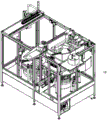
FIG. 1 is a perspective view of the pouch fill fitment of the present disclosure showing the pouch fill fitment and a rotatable flap assembly extending from an outlet of the pouch fill fitment and a pouch cleaning assembly located adjacent the inlet;
FIG. 2 is a top plan view of the pouch fill assembly, rotatable flap assembly and pouch cleaning assembly of the present disclosure;
FIG. 3 is a partial cross-sectional perspective view of the pouch fill assembly of the present disclosure, particularly illustrating the mobile assembly of the pouch fill assembly and its configuration, which is a cross-sectional rectangular configuration as well as a hoop-like configuration;
FIG. 4 is a partial top view of the inner and outer portions of the base wall of the removal fitment of the bag-filling fitment of the invention;
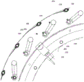
FIG. 5 is a perspective view, partially in section, of the pouch filling assembly of the present invention, particularly illustrating one of the plug removal stations of the plug removal station, wherein the plug is retained on the corresponding spout prior to removal;
fig. 6 is a partial top view, particularly illustrating the gripping assembly of the plug removal station of the plug removal assembly of the present disclosure;
FIG. 7 is a partial cross-sectional perspective view of the pouch filling assembly of the present disclosure, particularly illustrating one of the plug replacement stations, with the plug held at the plug holding structure for movement therefrom to the spout;
FIG. 8 is a partial top plan view particularly illustrating the gripping assembly of the plug replacement station of the plug replacement assembly of the present invention;
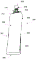
FIG. 9 is a perspective view of a bag configured for filling the bag fill fitment of the present disclosure;
FIG. 10 is a cross-sectional view of a plug positionable on the spout to seal the cavity thereof;
FIG. 11 is a perspective view of a plug positionable on the spout to seal the cavity;
FIG. 12 is a cross-sectional view of the plug retaining structure with a plug positioned thereon, particularly illustrating the retention seal flange and the spout engaging and sealing structure spaced from the plug retaining structure.
Detailed Description
While this invention is susceptible of embodiment in many different forms, there is shown in the drawings and will herein be described in detail specific embodiments, with the understanding that the present disclosure is to be considered as exemplary and not intended to be limited to the embodiments shown.
It should be understood that throughout the drawings, similar or analogous elements and/or components to those referred to herein may be identified by the same reference numerals. Furthermore, it will be appreciated that the figures are merely schematic representations of the invention and that some of the components may have been altered from actual scale for clarity of illustration.
Referring now to the drawings and in particular to fig. 1, a sterile bag fill fitment is generally indicated at 10. It should be understood that the aseptic bag filling assembly is configured for filling the bag in an aseptic environment and an aseptic zone. It should be understood that the sterile zone includes areas under a positive flow of sterile gas, typically sterile air, and that the product has been purged to sterility standards, such as the low acid food products disclosed in chapter 21 of the federal regulation relating to heat treatment packaged in sealed containers supervised by the FDA in the united states and the 3-a standards of health, inc and the European Health Engineering Design Group (EHEDG) standards.
A typical bag associated with the system is shown in fig. 9, generally at 300. As will be appreciated, the bag (in the capped configuration) is pre-sterilized prior to introduction into the filling apparatus 10 by, for example, gamma, X-ray, e-beam, or other sterilization process, such that the interior cavity of the bag is free of pathogens and a sterile environment. The pouch 300 includes a body 301 and a spout 310. The main body 301 includes a first side plate 302, a second side plate 303, and a lower supporting structure 306. The first side panel, second side panel, and lower gusset structure are connected together by a seal 308 to form a cavity 305 configured to hold a flowable material, such as a food item or the like. In many configurations, gusset structure 306 provides a base surface from which the bag can be in an upright configuration. Of course, in other configurations, the bag may be formed from more than two panels or from a single panel folded together, with the panels cooperating to form gussets at their lower ends. Furthermore, additional structures or gussets (e.g., side gussets) or gussetless constructions are also contemplated. Typically, the cavity is about 60ml to 500ml in size. More preferably, the size of the cavity is about 60ml and 180ml, and more preferably, the cavity is on the order of 90ml to 120 ml. Of course, variations are contemplated and the foregoing cavity volumes are merely exemplary and are not considered limiting. The bag has been sterilized by gamma sterilization or the like prior to introduction of the cartridge filling fitment. As such, the cavity is pathogen free and is a sterile environment. The plug has a gas-tight seal to prevent material from entering (or exiting) the spout. Typically, such bags are formed from a multi-layer polymeric structure, which may include metallic or metallized layers, and which may be coextruded and/or laminated.
The plug 320 shown in fig. 10 and 11 includes a body 350, a top wall 352, and an annular channel 354. The body includes an outer surface 360, a lower end 364, and an upper end 366. The body is a generally elongated cylindrical member that defines a lumen 362, the lumen 362 likewise being generally cylindrical. The top wall includes an outer surface 368 and generally defines an upper end of the body. The annular channel includes an upper wall 370, a lower wall 372 and an inner wall 374. The annular channel is configured as will be described for grasping and retaining the plug by the filling device. In the illustrated construction, the upper and lower walls are generally parallel to and spaced from each other. The upper wall is formed by an extension of the top wall, but other configurations are also contemplated. Additionally, it should be understood that other configurations that allow for grasping by an external clamp or other device are also contemplated.
Referring again to fig. 1 and 2, the bag-filling assembly 10 is configured to receive a bag, remove a plug, fill the bag, reposition or reattach the plug and exit the bag from the sterile field of the fill to a capping machine or the like. The pouch filling assembly 10 includes an inlet 12, an outlet 13, a movement assembly 14, a plug removal station 15, a filling station 16, and a rearrangement station 17. In the arrangement shown, the filling is a rotating filling, rotating about the axis 19, and four bags are processed simultaneously at each station. In other configurations, each station may process a greater or lesser number of bags simultaneously. In other configurations, a linear system may be used instead of a rotary system.
With additional reference to fig. 2, 3 and 4, the moving part 14 includes an inner wall 40, an outer wall 42, an upper wall 44 and a base wall 46. The inner wall 40 includes an upper end 50, a lower end 51, and an inner surface 52. The inner surface 52 is generally curved on a radius centered on the axis of rotation. The inner surface is generally planar between the upper and lower ends. It is contemplated that the nozzle may extend through the inner wall at the opening. Such nozzles may be configured to apply cleaning fluid, sterile air, or any other fluid as desired. They can be used during filling or during cleaning or sterilization. As will be explained, some of the movement fittings are movable in rotation about an axis relative to other parts thereof, which are generally fixed to a frame or the like. Thus, a portion of the moving assembly may rotate relative to other portions of the moving assembly.
The outer wall 42 includes an upper end 55, a lower end 56, and an inner surface 57. Typically, the heights of the outer and inner walls substantially correspond. In addition, the two are typically spaced apart from each other by a generally uniform predetermined distance. In this way, the outer wall is also curved about the same axis of rotation 19. In the illustrated construction, the outer wall may have a plurality of access openings, which may include a cut-out that generally forms a generally flat outer surface. A cover, which may be opaque, translucent or transparent, may be releasably attached thereto. Such a cover provides visual inspection and removal as needed. It will be appreciated that these openings and lids are typically provided with sealing gaskets or the like so as to be in a substantially sealed configuration.
The upper wall 44 includes an inner end 60, an outer end 61, and an inner surface 62. The inner end 60 generally corresponds to the upper end 50 of the inner wall 40. The outer end 61 generally corresponds to the upper end 55 of the outer wall 42. The upper wall 44 is generally substantially planar and generally provides a surface on which various components of the receptacle removal station, the filling station and the plug replacement station may be mounted.
The base wall 46 includes an inner portion 65, an outer portion 66 and cooperating to retain a clot 67. The base wall is generally perpendicular to each of the inner and outer walls. Inner portion 65 includes an upper surface 70, an inner chamber end 72, and an outer chamber end 82. The inner chamber end 72 generally corresponds to the lower end 51 of the inner wall 40. The outer edge 74 is generally spaced therefrom and defines a curve having a matching axis of rotation 19.
The mating retention slot 67 includes an inner profile 84 and an outer profile 85. It will be appreciated that the plurality of inner profiles are positioned in a spaced apart configuration along the outer edge 74 of the inner portion. In the illustrated arrangement, the inner profile includes a receiving area for receiving the bag and a retaining flange that prevents further relative movement of the bag and captures the bag. The inner edge of the outer portion includes an outer contour that cooperates with the inner contour to substantially prevent movement of the spout from the inner contour when the spout is positioned within the refill. The cooperation between the inner and outer profiles keeps the spout in the necessary configuration within the station and guides the spout from station to station. Notably, the spout is preferably captured by the gripping flange 316 such that the spout outlet tube is within the sterile zone, which is below the base wall, while the pouch 301 remains outside. In such a configuration, the bag, which is typically difficult to clean to sterile standards, may remain outside of the sterile field while the bag is being filled.
In the configured representation, the inner wall 40, outer wall 42, upper wall 44, and base wall 46 together form a hoop-like chamber that includes the sterile zone. The configuration has a generally rectangular cross-sectional configuration at any given point and is substantially uniform around its circumference. It should be understood that within the sterile zone, sterile conditions are maintained, as is the flow of disinfectant. The inner wall 40 and the inner portion 65 of the base wall 46 are connected to each other so as to be joined together. The two components are identical. Similarly, the outer portion 66 of the base wall 46 is joined with the upper wall 44 and the outer wall 42. In the illustrated construction, the inner portion of the base wall is configured to rotate while the outer portion of the base wall is configured to be substantially stationary.
In this configuration, the outer profile of the mating retention slot 67 is substantially uniformly circular, with the inner profile including the slots and channels directed toward the inner profile 84. In this manner, the inner and outer edges are configured to abut in close proximity to minimize sterilant passing therethrough. It will be appreciated that in some configurations, a seal may be provided, however it has been found that the change caused by the internal profile provides a small opening that allows a relatively insignificant amount of sterilant (i.e. sterile air or other gas).
To further reduce the throughput of sterilant (i.e., sterile air or other gas), chamber seals are provided adjacent the surfaces of the moving parts that have relative motion. For example, an upper inner wall seal 48 is provided at an upper end 50 of the inner wall 40 to seal the upper inner wall seal against all of the upper ends 44. In the illustrated construction, the seal includes a pair of opposing ridges 87 and a central valley 89 therebetween. The ridge extends upwardly from the inner wall and sealingly engages the inner surface 62 of the upper wall. A bactericide, cleaning fluid or the like may be injected therebetween so as to be located within the valleys 89 therebetween to provide additional protection against the introduction of microorganisms or the passage of microorganisms. It will be appreciated that over time, such seals may wear due to the continued movement of the inner wall relative to the upper wall.
It is to be understood that the present disclosure is not limited to the disclosed relative wall movement. That is, it is contemplated that the base wall may move relative to each of the other walls, that multiple walls may move in opposite directions, and other solutions. It is also contemplated that the base wall may remain stationary with the other walls, e.g., the upper wall may move relative thereto.
The plug removal assembly 15 shown in figures 5 and 6 comprises a plurality of separate stations (in this case four stations). The plurality of separation stations are angularly positioned relative to each other in a spaced apart configuration. A single plug removal station 100 will be described with the understanding that the other plug removal stations are substantially identical thereto. The plug removal station 100 includes an actuator assembly 102, a gripping fitting 104, and a plug retaining structure 106. The task of the plug removal station is to capture the plug, remove it and place it in the plug holding structure.
The actuator assembly includes an arm 110 and a movement mechanism 111. The motion mechanism may include pneumatic, electric, or cam-driven components that may guide the arm through rotation and translation. The moving mechanism is mounted on the upper wall such that the arm extends through the upper wall toward the base wall to cover an inner portion thereof. As gaskets and the like provide a sealing engagement between the components and the aseptic chamber to prevent the passage of materials (i.e., sterilant or other materials and non-sterile items) therebetween. The arm 110 includes an upper end 112 and a lower end 114. The arm is configured to extend into and out of the motion mechanism. The arm is offset from the mating retention slot, such as slot 67 of base wall 46.
The capture fitting 104 shown in fig. 5 and 6 includes an inner end 120, an outer end 122, a first side 124, a second side 126, and a capture slot 128. A catch fitting is mounted to lower end 112 proximate inner end 120 of arm 110. The gripping fitting is generally configured to extend substantially perpendicular to the arm 110 of the actuator assembly. In the configuration shown, the relationship is vertical and the gripping appendage is substantially planar. Of course, this is merely exemplary, and other relationships are contemplated. Since the outer end is configured to be both rotatable and translatable, the outer end is spaced from the arm and its axis of rotation. It is envisaged that more complex multi-link configurations may be envisaged as well.
A capture slot 128 is positioned proximate the outer end 122 and has an opening toward the first side 124. The capture slot 128 includes an inlet region 130 and a retention portion 132. The inlet region includes an opening having a beveled edge. The retaining portion is generally semi-circular and includes a seating edge 136 and an inclined edge 137. It will be appreciated that the retaining portion is configured to enter the annular channel 354 of the plug 320 and thereby releasably retain the plug. The transition from the inlet region to the retention portion elastically deforms the plug, thereby providing some resistance to removal of the plug from within the insertion slot.
The plug retaining structure 106 includes elongate post members 140, the elongate post members 140 being positioned in a spaced apart manner in corresponding mating retaining slots 67 of the base wall 46. Elongate post member 140 includes a lower end 142, an upper end 144, and a seat flange 146. The lower end 142 extends from the upper surface of the interior portion of the base wall 46 with the elongate post members thereof extending substantially vertically upwardly to an upper end 144. Between the upper and lower ends, a seat flange 146 is provided to define a plug portion 149 thereon. The plug portion is configured to receive a plug thereon, wherein the socket flange defines a travel distance of the plug along the elongate post member. The cross-sectional configuration of the plug retention structure with the plug portion thereon is disclosed in fig. 12.
The operation of the plug removal station 100 will be briefly described here, and the operation of the plug removal station 100 will be described in more detail below. More specifically, the operation begins with positioning the pouch within a mating retention slot associated with the plug removal station. Next, the actuator assembly guides the arm 110 so that the gripping fitting 104, and in particular the capture slot, is introduced into the annular channel 354 of the plug of the bag in the mating retention slot of the base wall.
Once the plug is engaged with the grasping assembly 104, the actuator assembly 102 is directed upward to remove the plug from the spout. Once removed, the grasping assembly 104 is rotated by the actuator assembly away from the spout and into a position where the plug covers the plug retaining structure 106. Once in place and referring to fig. 12, the plug is directed downward by the actuator assembly such that plug portion 149 extends into interior cavity 362 of plug body 350. Once the plug bottom comes out or reaches the seat ledge 146, or is otherwise positioned on the plug retaining structure sufficiently to ensure that it cannot be inadvertently disconnected or disengaged from the plug retaining structure, the actuator assembly is again rotated, this time away from the plug retaining structure. This movement separates the plug from the gripping fitting. The gripping appendage is removed leaving the removed plug on the elongate post member with the spout in an open condition. Advantageously, the structure of the plug configured to seal and capture the outlet tube of the spout is spaced from the plug retaining structure retained within the boundaries of the internal cavity of the plug body. As a result, inadvertent damage to these structures of the plug can be avoided.
The fill fitting 91 is shown in fig. 2 and is positioned in angular spacing from the plug removal fitting. In the illustrated configuration, the fill assembly 91 includes a plurality of fill heads, four spaced apart fill heads having the same spacing as the spacing between plug removal stations. The fill head is configured to engage and fill the bag with a flowable material supplied to the fill head. The filling head may be selectively aligned, engaged and disengaged with the filling head as prescribed to fill the bag and prepare the bag for repositioning the plug on the spout to seal the cavity of the bag. It should be understood that any number of different fill valves may be used with the fill head.
The plug replacement assembly 17 is shown in fig. 7 and 8 as including a plurality of plug replacement stations. In the configuration shown, a total of four reconfiguration stations are shown. It will be appreciated that they are angularly spaced from one another so as to be positioned at substantially the same spacing as the plug removal and filling stations. It is envisaged that in some embodiments the plug removal assembly and plug replacement accessory may comprise the same actuator and gripping accessory, the bag being configured to move between the plug removal station and the filling station and back to replace the plug.
The plug replacement station 200 is substantially identical in structure to the plug removal station 100. Accordingly, similar components have the same reference numerals increased by 100. The plug replacement station 200 includes an actuator assembly 202, a gripping fitting 204 that mates with the plug retention structure 106. The task of the plug replacement station is to capture the plug from the plug retaining structure, remove it therefrom, and place the plug from the place of removal on the spout of the respective bag.
The actuator assembly includes an arm 210 and a motion mechanism 211. The motion mechanism may include pneumatic, electric, or cam-driven components that may guide the arm through rotation and translation. The moving mechanism is mounted on the upper wall such that the arm extends through the upper wall toward the base wall to cover an inner portion thereof. As gaskets and the like provide a sealing engagement between the components and the aseptic chamber to prevent the passage of materials (i.e., sterilant or other materials and non-sterile items) therebetween. The arm 210 includes an upper end 212 and a lower end 214. The arm is configured to extend into and out of the motion mechanism. The arm is offset from the mating retention slot, such as slot 67 of base wall 46.
The gripping fitting 204 is shown in fig. 7 and 8 as including an inner end 220, an outer end 222, a first side 224, a second side 226, and a capture slot 228. A catch fitting is mounted to the lower end 212 proximate the inner end 220 of the arm 210. The gripping fitting is generally configured to extend substantially perpendicular to the arm 210 of the actuator assembly. In the configuration shown, the relationship is vertical and the gripping appendage is substantially planar. Of course, this is merely exemplary, and other relationships are contemplated. Since the outer end is configured to be both rotatable and translatable, the outer end is spaced from the arm and its axis of rotation. It is envisaged that more complex multi-link configurations may be envisaged as well.
The capture slot 228 is positioned proximate the outer end 222 and has an opening toward the first side 224. The capture groove 228 includes an inlet region 230 and a retention portion 232. The inlet region includes an opening having a beveled edge. The retaining portion is generally semi-circular and includes a seating edge 236 and an inclined edge 237. It should be appreciated that the retaining portion is configured to enter the annular channel 354 of the plug 320 and thereby releasably retain the plug. The transition from the inlet region to the retention portion elastically deforms the plug, thereby providing some resistance to removal of the plug from within the insertion slot.
As the base wall rotates, the plug retaining structure 106 (which includes the same structure) rotates, the plug retaining structure rotates with it, and the same plug retaining structure interfaces with each of the plug removal fitting and the plug replacement fitting. As described above, the plug retaining structure includes elongate post members 140, the elongate post members 140 being positioned in a spaced apart orientation from the corresponding mating retaining slots 67 of the base wall 46. Elongate post member 140 includes a lower end 142, an upper end 144, and a base flange 146. The lower end 142 extends from the upper surface of the interior portion of the base wall 46 and the elongate post member extends substantially vertically upwardly to an upper end 144. Between the upper and lower ends, the seat flange 146 is configured to define a plug portion 149 thereon. The plug portion is configured to receive a plug thereon, wherein the socket flange defines a travel distance of the plug along the elongate post member.
In short, the operation of the plug replacement station 200 is generally reversed from that of the plug removal station. In particular, the plug is initially positioned on the plug retention feature 106 associated with the pocket within the mating retention slot 67. The gripping fitting 204 is rotated and/or translated such that the catch slot 228 of the gripping fitting engages the plug, directing the plug into the inlet region 230 and into the retention portion 232. Once in the retaining portion of the grasping assembly 204, the plug may be translated upward to disengage the plug from the elongate post member 140.
Next, the plug may be rotated and translated so as to be positioned over the spout of the respective pouch. Once in place, the plug may be directed to engage the spout and seal the opening of the spout. Once engagement is complete, the gripping fitting may be rotated away from the plug to release the retaining portion 232 of the gripping fitting 204 from within the annular channel 354. At this point, the plug has been repositioned and the plug replacement station assembly has been separated therefrom.
The outlet 13 is shown as including a switching zone where the bag is transferred out of the sterile zone from the mating retention slot 67 and into the closure assembly, and in the embodiment shown is a rotating closure assembly. The closure assembly connects the cap to the spout (preferably rotatably) while coupling the cap to the plug so that the two move in unison.
The method of filling the bag through the bag filling fitment will be described with respect to four different sets of bags. The first set of bags will be traced from the inlet to the outlet and the second to fourth bags from the inlet to the station corresponding to the station in which such bags are located when the first set of bags exit from the sterile zone at the outlet.
In particular, the first set of pouches is first introduced into the mating retention slot of the base wall by capturing the spout within the mating retention slot and, in turn, rotation of the inner portion of the base wall relative to the upper wall (and outer wall). As four plug removal stations, a filling station and a plug replacement station are disclosed, it being understood that four bags are provided. It will be further understood that it is contemplated that a greater or lesser number of stations may be provided for respective bags. It will also be appreciated that not every station may be active for every cycle. For example, one of the stations may be inactive, wherein three bags will be processed simultaneously.
As the first set of pockets are sequentially guided into the mating retention slots, they are oriented substantially simultaneously to a position associated with the plug removal station 100. When at the respective plug removal station, the respective actuator assembly 102, gripping fitting 104 and plug retaining structure 106 are provided. The actuator assembly 102 guides the arms so that the grasping assembly 104 can grasp a respective plug from a respective pocket. The gripping fitting is then guided into contact with the plug, thereby guiding the plug into the holding portion 132 of the gripping groove of the gripping fitting. This preferably occurs simultaneously at each station.
Once engaged, the actuator assembly turns the gripping fitting up to remove the plug from the spout. Once removed, the actuator assembly rotates the gripping fitting with the plug to a position where its plug covers the plug retaining structure. Once in the overlying position, the actuator assembly is converted to guide the plug into contact with the plug retaining structure 106 and guide the plug portion 149 into the internal cavity 362. Also, the process preferably occurs simultaneously at each station.
With the steps of the plug removal station completed, the inner portion of the base wall is rotated to guide the first pocket (now uncovered) from the plug removal station to the gasoline station. It will be appreciated that as the first set of pockets is directed to the service station, the second set of pockets is sequentially introduced into the mating retention slots and rotated to the plug removal station. The above process was repeated with a second pouch.
The first set of bags is connected to the gasoline station 91 and filled with flowable material provided to the gasoline station. Due to the coordinated movement and timing, the plugs have been removed from the second set of bags when the bags are filled. At this point, the inner portion of the base wall is rotated and the first set of pockets are located at various stations in the plug replacement fitting. The second pocket is rotated from the plug removal fitting to the filling fitting and in particular at the respective filling station. The third pocket has been introduced into the corresponding mating retention slot and guided to the plug removal fitting.
When the plug is removed from the third set of pockets and the second set of pockets is filled, the first set of pockets have had the plug reinserted. Notably, the plug retention structure 106 is connected to the inner portion 65 of the base wall, so that when the inner portion of the base wall is rotated, the pocket rotates with the plug removed from the pocket. Thus, when refilled, the bag is re-capped with the same plug.
More specifically, at each plug replacement station, the gripping assembly 204 is rotated and/or translated to guide the retention portion 232 of the capture slot 228 into the annular channel 354 of the plug. Once the plug has been removably connected to the grasping assembly, the actuator assembly is directed to translate upwardly to disengage the plug from the plug portion 149 of the elongate post member 140. Once cleared, the plug is rotated and/or translated so that the plug covers the spout of the respective pouch. Once positioned, the plug may be translated to engage the spout and seal the cavity of the spout. Once positioned in sealing engagement with the spout, the actuator assembly may rotate the gripping fitting such that the annular channel is released from the gripping slot separating the plug from the gripping fitting. The grasping assembly can then be rotated and/or translated out of the path of the continuous bag.
When the plug replacement is completed for the first group of bags, the second group of bags has completed filling at the respective filling station. In addition, the plug has been removed from the first pocket and positioned on the corresponding plug retaining structure.
As the inner portion of the base wall is rotated again, the first group of bags approaches the outlet, where the bags are directed out of the sterile zone and sequentially transferred to a rotary capping machine. Simultaneously, the second envelope is sent from the filling station to the plug replacement station; feeding the third pocket from the plug removal station to a filling station; a fourth pocket is introduced into each of the mating retention slot and plug removal stations in sequence. The cycle may continue with a successive set of bags exiting through the outlet in a full condition and a new set of bags entering through the inlet. It will be appreciated that the bag at the inlet for the filling is sterilised internally and that the spout of the bag is sterilised already before entering the filling. It will be appreciated that, since the spout is sterilized prior to entry, and since the sterile zone maintains a positive flow throughout the sterile zone, pathogens are excluded from entering the sterile zone through openings, such as those present due to the nature of the fit between the inner portion of the base wall and the outer portion of the base wall and the cooperating retaining groove.
The foregoing description merely illustrates and describes the invention and the invention is not limited thereto except as the appended claims so limited since modifications will occur to those skilled in the art having the benefit of the foregoing disclosure without departing from the scope of the invention.
Claims (14)
1. Filling device for aseptic filling of bags, comprising:
a pouch fill assembly comprising:
a movement assembly defining a sterile zone, the movement assembly configured to direct a pouch having a spout and a plug sealing the spout from an inlet to an outlet through the pouch fill assembly;
the plug removal assembly has at least one plug removal station, the plug removal station further comprising:
a grasping assembly positioned within the sterile zone structurally configured to releasably capture a portion of the plug;
a plug retaining structure located within the sterile zone structurally configured to releasably retain the plug upon removal from the spout; and
an actuator assembly structurally configured to direct the plug between the spout and the plug retaining structure; and
a filling assembly having at least one filling station structurally configured to dispense a flowable material into the pouch through the spout;
wherein the movement assembly further comprises a base wall, a portion of which is rotatably positioned relative to the plug removal assembly and the pouch fill assembly, wherein a mating retention slot is defined that is structurally configured to retain a pouch through the spout, the base wall comprising an upper surface, wherein the plug retention structure is positioned in a spaced apart orientation from the mating retention slot and extends from the upper surface, wherein the grasping assembly is structurally configured to extend between the mating retention slot and the plug retention structure.
2. The filling device of claim 1 wherein the actuator comprises an arm translatable and rotatable relative to the base wall and having a catch fitting located adjacent a lower end thereof, the catch fitting having a first side and a second side, wherein a catch slot is defined in the first side, the catch slot having a retaining portion configured to releasably engage the spout.
3. The filling device of claim 2 wherein the plug retaining structure comprises an elongate post member extending outwardly from an upper surface of the base wall.
4. Filling device for aseptic filling of bags, comprising:
a pouch fill assembly comprising:
a movement assembly defining a sterile zone, the movement assembly configured to direct a pouch having a spout and a plug sealing the spout from an inlet to an outlet through the pouch fill assembly;
the plug removal assembly has at least one plug removal station, the plug removal station further comprising:
a grasping assembly positioned within the sterile zone structurally configured to releasably capture a portion of the plug;
a plug retaining structure located within the sterile zone structurally configured to releasably retain the plug upon removal from the spout; and
an actuator assembly structurally configured to direct the plug between the spout and the plug retaining structure; and
a filling assembly having at least one filling station structurally configured to dispense a flowable material into the bag through the spout, wherein the removal assembly further comprises:
a hoop member defined by an inner wall, an outer wall, an upper wall, and a base wall, the hoop member having an axis of rotation, the base wall further comprising:
an inner portion and an outer portion, one of the inner portion and the outer portion fixedly coupled to the upper wall, wherein the other of the inner portion and the outer port is rotatably positioned relative to the upper wall.
5. The filling device of claim 4 wherein the inner portion is rotatably positioned relative to the upper wall:
the cooperating retaining slot portion of the inner portion guides movement of the spout and, in turn, movement of the pouch;
the plug removal station and the stuffing station are coupled to the upper wall such that an inner portion of the base wall is rotatably movable relative to the plug removal station and the stuffing station; and
plug retention structure is positioned adjacent the mating retention slot so as to extend from an upper surface of the inner portion of the base wall.
6. The filling device of claim 5 wherein the inner wall is fixedly coupled to the inner portion of the base wall so as to rotate together, wherein the outer wall is fixedly coupled to the upper wall and the outer portion of the base wall, wherein the inner wall rotates relative to each of them.
7. The filling device of claim 6 further comprising a chamber seal located between the inner wall and the upper wall, the chamber seal comprising a pair of opposing ridges extending from the inner wall to the upper wall and sealingly engaging the upper wall with a valley therebetween, the valley structurally configured to retain a fluid or gas therebetween.
8. The filling device of claim 1 further comprising a plug replacement assembly having at least one plug replacement station, the plug replacement station further comprising:
a grasping assembly located within the sterile zone and structurally configured to releasably capture a portion of the plug;
a plug retaining structure located within the sterile zone structurally configured to releasably retain the plug upon removal from the spout; and
an actuator assembly structurally configured to direct the plug between the spout and the plug retaining structure.
9. The filling device of claim 8 wherein the movement assembly further comprises a rotational configuration having an axis of rotation, wherein the spout is rotatably movable along the rotational configuration and with the plug removal assembly, the filling assembly and the plug replacement assembly are sequentially positioned in the rotational configuration, the spout and the plug sequentially entering the filling assembly and the plug replacement assembly from the plug removal assembly as they rotate.
10. Filling device for aseptic filling of bags, comprising:
a pouch fill assembly comprising:
defining a sterile zone movement fitment defining a hoop, a portion of the movement fitment being rotatable about an axis of rotation and relative to another portion thereof that is substantially stationary, the portion of the movement fitment including at least one mating retention slot configured to releasably receive a spout of the pouch;
a plug removal assembly having at least one plug removal station coupled to a fixed portion of the movement assembly, wherein the at least one plug retaining structure is connected to a rotatable portion of the movement assembly and is adjacent to and rotatable with each of the mating retaining slots;
a fill assembly having at least one fill head coupled to a fixed portion of the movement assembly downstream of the plug removal assembly;
a plug replacement assembly having at least one plug replacement station coupled to a stationary portion of the movement assembly downstream of the fill assembly;
wherein the rotatable portion is structurally configured to rotate in sequence at least one pocket and at least one plug associated with the pocket to each of the plug moving, stuffing and plug replacing fittings, the plug connected to the pocket being removed, then the pocket filled, then the plug replaced on the same pocket from which the insert was removed, and the plug rotated with the pocket connected to the rotatable portion;
wherein the moving assembly further includes an inner wall, an outer wall spaced from the inner wall, an upper wall, and a base wall spaced from the upper wall, the walls cooperating to define a generally ring-like configuration, the base wall having an inner portion and an outer portion, one of the inner portion and the outer portion being rotatably positioned relative to at least one of the outer wall, the inner wall, and the upper wall.
11. The filling device of claim 10 wherein the inner portion of the base wall is rotatable relative to the outer portion of the base wall and the upper wall.
12. The filling device of claim 11 wherein the movement assembly has a substantially rectangular cross-sectional configuration.
13. Filling device for aseptic filling of bags, comprising:
a pouch fill assembly comprising:
defining a sterile zone movement assembly, the movement assembly defining a hoop, a portion of the movement assembly being rotatable about an axis of rotation and relative to another portion thereof that is substantially stationary, the rotatable portion of the movement assembly including at least one cooperating retention slot configured to releasably receive a spout of the pouch;
a plug removal assembly having at least one plug removal station coupled to a fixed portion of the movement assembly, wherein the at least one plug retaining structure is connected to a rotatable portion of the movement assembly and is adjacent to and rotatable with each of the mating retaining slots;
a fill assembly having at least one fill head coupled to a fixed portion of the movement assembly downstream of the plug removal assembly;
a plug replacement assembly having at least one plug replacement station coupled to a stationary portion of the movement assembly downstream of the fill assembly;
wherein the rotatable portion is structurally configured to rotate in sequence at least one pocket and at least one plug associated with the pocket to each of a plug movement assembly, a fill assembly and a plug replacement assembly, the plug connected to the pocket being removed, then the pocket being filled, then the plug being replaced on the same pocket from which the insert was removed, and the plug being rotated with the pocket connected to the rotatable portion, wherein the plug removal assembly comprises four stations, the plug replacement assembly comprises four stations, and the fill assembly comprises four fill stations, the base wall comprises sixteen arrangement retaining slots positioned in a spaced apart manner and comprising sixteen plug retaining structures positioned adjacent to the sixteen mating retaining structures.
14. The filling device of claim 13 wherein the plug retaining structure comprises an elongate post member extending from the base wall and including a lower end and an upper end.
Applications Claiming Priority (3)
| Application Number | Priority Date | Filing Date | Title |
|---|---|---|---|
| US14/860,686 US10189591B2 (en) | 2015-09-21 | 2015-09-21 | Rotary filling device for aseptic filling of pouches |
| US14/860686 | 2015-09-21 | ||
| PCT/US2016/052464 WO2017053226A1 (en) | 2015-09-21 | 2016-09-19 | Rotary filling device for aseptic filling of pouches |
Publications (2)
| Publication Number | Publication Date |
|---|---|
| CN108290649A CN108290649A (en) | 2018-07-17 |
| CN108290649B true CN108290649B (en) | 2020-06-26 |
Family
ID=58276625
Family Applications (1)
| Application Number | Title | Priority Date | Filing Date |
|---|---|---|---|
| CN201680067726.4A Active CN108290649B (en) | 2015-09-21 | 2016-09-19 | Rotary filling device for aseptic filling of bags |
Country Status (6)
| Country | Link |
|---|---|
| US (2) | US10189591B2 (en) |
| EP (1) | EP3353071B1 (en) |
| CN (1) | CN108290649B (en) |
| AU (1) | AU2016328306B2 (en) |
| BR (1) | BR112018005122B1 (en) |
| WO (1) | WO2017053226A1 (en) |
Families Citing this family (11)
| Publication number | Priority date | Publication date | Assignee | Title |
|---|---|---|---|---|
| US10524980B2 (en) * | 2016-09-13 | 2020-01-07 | Vanrx Pharmasystems, Inc. | Apparatus and method for aseptically filling pharmaceutical containers with a pharmaceutical fluid using rotary stage |
| IT201700047199A1 (en) * | 2017-05-02 | 2018-11-02 | Goglio Spa | Pressure cap and airtight container equipped with this pressure cap |
| EP3687808B1 (en) | 2018-07-13 | 2023-04-12 | Hewlett-Packard Development Company, L.P. | Coupling systems |
| WO2020013858A1 (en) | 2018-07-13 | 2020-01-16 | Hewlett-Packard Development Company, L.P. | Collar for fluid barrier |
| WO2020013852A1 (en) | 2018-07-13 | 2020-01-16 | Hewlett-Packard Development Company, L.P. | Pliable print liquid supply reservoirs with offset spout |
| CN112423988B (en) | 2018-07-13 | 2022-08-02 | 惠普发展公司,有限责任合伙企业 | Nozzle with inclined clamping flange for printing liquid supply device |
| US11597209B2 (en) | 2018-07-13 | 2023-03-07 | Hewlett-Packard Development Company, L.P. | Clamp plates with wedge-shaped fork ends for a print liquid supply |
| FR3126123B1 (en) | 2021-08-12 | 2023-07-28 | Smurfit Kappa Bag In Box | Process and machine for filling bags. |
| DE102021121177A1 (en) * | 2021-08-16 | 2023-02-16 | Krones Aktiengesellschaft | Apparatus for handling containers with a supported clean room |
| US11999519B2 (en) | 2022-08-04 | 2024-06-04 | Scholle Ipn Corporation | Filler assembly and method of filling a pouch |
| CN118047107B (en) * | 2024-04-12 | 2024-08-09 | 常州市飞利达医用制品有限公司 | Annular conveying batch disinfection equipment for medical packaging bags |
Citations (7)
| Publication number | Priority date | Publication date | Assignee | Title |
|---|---|---|---|---|
| CN1203881A (en) * | 1997-06-27 | 1999-01-06 | 利乐拉瓦尔集团及财务有限公司 | Unit for transferring and tipping sealed packages containing pourable food products |
| CN2570174Y (en) * | 2002-09-17 | 2003-09-03 | 哈尔滨赛德技术发展有限公司 | Full-automatic germ-free liquid packager |
| CN2632061Y (en) * | 2003-07-23 | 2004-08-11 | 广东轻工业机械集团有限公司 | Small size integrated apparatus for cleaning, filling and capping |
| CN201296392Y (en) * | 2008-11-01 | 2009-08-26 | 魏徽 | Racking machine package receiving-clamping device |
| CN201614022U (en) * | 2010-03-23 | 2010-10-27 | 温州名瑞机械有限公司 | Bag-feeding type full-automatic packaging machine |
| CN103193001A (en) * | 2011-12-23 | 2013-07-10 | 阿法拉伐股份公司 | An aseptic filling machine |
| US10059476B2 (en) * | 2013-05-21 | 2018-08-28 | John Bean Technologies S.P.A. | Aseptic filler for flowable products |
Family Cites Families (22)
| Publication number | Priority date | Publication date | Assignee | Title |
|---|---|---|---|---|
| US3499568A (en) | 1967-12-28 | 1970-03-10 | Jose Vinas Riera | Stopper system for biological containers |
| US3596430A (en) * | 1968-12-09 | 1971-08-03 | Laurence P Parish | Automatic milk packaging machine |
| US4120134A (en) * | 1977-07-05 | 1978-10-17 | Scholle Corporation | Apparatus for and method of filling flexible containers |
| US4363338A (en) * | 1980-09-08 | 1982-12-14 | Brown Albert M | Liquid filling machine |
| JPS57117349U (en) | 1981-01-14 | 1982-07-21 | ||
| US4458734A (en) | 1982-01-29 | 1984-07-10 | Scholle Corporation | Apparatus and method for aseptically filling a container |
| US4498508A (en) * | 1983-02-04 | 1985-02-12 | Scholle Corporation | Container filler |
| IT1269243B (en) | 1994-07-27 | 1997-03-26 | Rossi & Catelli Spa | MACHINE FOR PACKAGING CONTAINERS IN ASEPTIC ENVIRONMENT |
| SE511170C2 (en) * | 1997-01-29 | 1999-08-16 | Tetra Laval Holdings & Finance | Ways of handling, filling and sealing packaging containers |
| IL140486A0 (en) * | 1998-06-29 | 2002-02-10 | Astrapak Ltd | Plug and gland aseptic package system |
| JP4590805B2 (en) | 2001-08-28 | 2010-12-01 | 凸版印刷株式会社 | Aseptic filling method for pouch with spout |
| JP4788086B2 (en) | 2001-09-07 | 2011-10-05 | 四国化工機株式会社 | Packaging machinery |
| JP2003237742A (en) | 2002-02-13 | 2003-08-27 | Toppan Printing Co Ltd | Method of aseptically filling pouch having spout |
| JP2002321715A (en) | 2002-04-09 | 2002-11-05 | Dainippon Printing Co Ltd | Asceptic filling method and system |
| US6889482B2 (en) * | 2002-10-10 | 2005-05-10 | Fogg Filler Company | Filler device sub-assembly |
| US7373959B2 (en) * | 2004-03-12 | 2008-05-20 | Scholle Corporation | Apparatus and method for aseptic serial filling of containers |
| JP4794175B2 (en) | 2005-01-31 | 2011-10-19 | 株式会社細川洋行 | Structure of spout part, spout member and cap member used for spout part |
| GB0708272D0 (en) * | 2007-04-28 | 2007-06-06 | Imi Vision Ltd | Pouch handling mechanism |
| GB2452055A (en) * | 2007-08-22 | 2009-02-25 | Flexifill Ltd | Aseptic container filling |
| DE102010049263A1 (en) | 2010-10-25 | 2012-04-26 | Khs Gmbh | Method and equipment for sterile or aseptic filling and sealing of packaging |
| DE102011012879A1 (en) * | 2011-03-02 | 2012-09-06 | Haver & Boecker Ohg | Apparatus and method for filling valve bags with pourable goods |
| JP6404612B2 (en) | 2014-06-23 | 2018-10-10 | 株式会社細川洋行 | Production method and accumulation of pouch with spout in which contents are aseptically filled |
-
2015
- 2015-09-21 US US14/860,686 patent/US10189591B2/en active Active
-
2016
- 2016-09-19 EP EP16849392.2A patent/EP3353071B1/en active Active
- 2016-09-19 BR BR112018005122-5A patent/BR112018005122B1/en active IP Right Grant
- 2016-09-19 CN CN201680067726.4A patent/CN108290649B/en active Active
- 2016-09-19 AU AU2016328306A patent/AU2016328306B2/en active Active
- 2016-09-19 WO PCT/US2016/052464 patent/WO2017053226A1/en active Application Filing
-
2019
- 2019-01-29 US US16/260,846 patent/US11261000B2/en active Active
Patent Citations (7)
| Publication number | Priority date | Publication date | Assignee | Title |
|---|---|---|---|---|
| CN1203881A (en) * | 1997-06-27 | 1999-01-06 | 利乐拉瓦尔集团及财务有限公司 | Unit for transferring and tipping sealed packages containing pourable food products |
| CN2570174Y (en) * | 2002-09-17 | 2003-09-03 | 哈尔滨赛德技术发展有限公司 | Full-automatic germ-free liquid packager |
| CN2632061Y (en) * | 2003-07-23 | 2004-08-11 | 广东轻工业机械集团有限公司 | Small size integrated apparatus for cleaning, filling and capping |
| CN201296392Y (en) * | 2008-11-01 | 2009-08-26 | 魏徽 | Racking machine package receiving-clamping device |
| CN201614022U (en) * | 2010-03-23 | 2010-10-27 | 温州名瑞机械有限公司 | Bag-feeding type full-automatic packaging machine |
| CN103193001A (en) * | 2011-12-23 | 2013-07-10 | 阿法拉伐股份公司 | An aseptic filling machine |
| US10059476B2 (en) * | 2013-05-21 | 2018-08-28 | John Bean Technologies S.P.A. | Aseptic filler for flowable products |
Also Published As
| Publication number | Publication date |
|---|---|
| BR112018005122B1 (en) | 2021-10-19 |
| WO2017053226A1 (en) | 2017-03-30 |
| AU2016328306A1 (en) | 2018-04-05 |
| US11261000B2 (en) | 2022-03-01 |
| BR112018005122A2 (en) | 2018-10-02 |
| US20190152637A1 (en) | 2019-05-23 |
| EP3353071A1 (en) | 2018-08-01 |
| EP3353071B1 (en) | 2020-03-18 |
| AU2016328306B2 (en) | 2019-08-29 |
| CN108290649A (en) | 2018-07-17 |
| US20170081060A1 (en) | 2017-03-23 |
| US10189591B2 (en) | 2019-01-29 |
| EP3353071A4 (en) | 2019-04-10 |
Similar Documents
| Publication | Publication Date | Title |
|---|---|---|
| CN108290649B (en) | Rotary filling device for aseptic filling of bags | |
| AU2019205020B2 (en) | Method for aseptic filling of pouches | |
| AU2016328308B2 (en) | Pouch assembly having a plug | |
| US6256964B1 (en) | Method of handling, filling and sealing packaging containers | |
| EP3353072B1 (en) | Pouch cleaning assembly for an aseptic filler | |
| CN102295083A (en) | Method and device for transferring material |
Legal Events
| Date | Code | Title | Description |
|---|---|---|---|
| PB01 | Publication | ||
| PB01 | Publication | ||
| SE01 | Entry into force of request for substantive examination | ||
| SE01 | Entry into force of request for substantive examination | ||
| GR01 | Patent grant | ||
| GR01 | Patent grant |