CN1082861C - Ultrasonic vibration soldering apparatus and resonator used therein - Google Patents
Ultrasonic vibration soldering apparatus and resonator used therein Download PDFInfo
- Publication number
- CN1082861C CN1082861C CN97112970A CN97112970A CN1082861C CN 1082861 C CN1082861 C CN 1082861C CN 97112970 A CN97112970 A CN 97112970A CN 97112970 A CN97112970 A CN 97112970A CN 1082861 C CN1082861 C CN 1082861C
- Authority
- CN
- China
- Prior art keywords
- solder
- resonator
- supporting part
- case
- hole
- Prior art date
- Legal status (The legal status is an assumption and is not a legal conclusion. Google has not performed a legal analysis and makes no representation as to the accuracy of the status listed.)
- Expired - Fee Related
Links
Images


Classifications
-
- B—PERFORMING OPERATIONS; TRANSPORTING
- B23—MACHINE TOOLS; METAL-WORKING NOT OTHERWISE PROVIDED FOR
- B23K—SOLDERING OR UNSOLDERING; WELDING; CLADDING OR PLATING BY SOLDERING OR WELDING; CUTTING BY APPLYING HEAT LOCALLY, e.g. FLAME CUTTING; WORKING BY LASER BEAM
- B23K3/00—Tools, devices, or special appurtenances for soldering, e.g. brazing, or unsoldering, not specially adapted for particular methods
- B23K3/06—Solder feeding devices; Solder melting pans
- B23K3/0646—Solder baths
- B23K3/0653—Solder baths with wave generating means, e.g. nozzles, jets, fountains
Abstract
A support portion for attaching a horn main body to a solder tank is provided on the horn main body at a nodal point and ultrasonic vibration from an external transducer is transmitted to solder in the solder tank through the horn main body.
Description
The present invention relates to a kind of workpiece be immersed ultrasonic brazing unit in the solder, it applies ultrasonic vibration to the solder liquation that is heated and melt in a solder case.
Known ultrasonic brazing is: by the solder liquation that is heated in a solder case and melt being applied ultrasonic vibration and a workpiece is immersed in the solder, but do not make the workpiece part coated with flux that needs welding.
In such ultrasonic brazing, once the someone made such design, that is: make ultrasonic vibration impose on workpiece by solder from a ultrasonic horn, the part that solder is applied vibration of described ultrasonic horn preferably is connected on the position that is lower than solder liquid level in the case of solder case, described ultrasonic horn is to connect by this way, that is, it passes the wall of solder case and faces mutually with the workpiece that is immersed in the molten solder.When the workpiece brazing area of facing mutually with ultrasonic horn increased, the ultrasonic wave of ultrasonic horn applies the zone also to be increased.Therefore, when the distance that applies the zone when the oscillator that is connected in ultrasonic horn and ultrasonic wave increases, the Oscillation Amplitude in this zone will be more and more littler, thereby make solder adhere to workpiece with uneven thickness easily.
As shown in figure 17, by in the horn main body 1-10a of ultrasonic horn 1-10, forming groove 1-10b, 1-10c, 1-10d, 1-10e can improve amplitude state, and except soldering, this ultrasonic horn also can be used for connecting or other can utilize the occasion of ultrasonic vibration.Figure 17 a is the plane of ultrasonic horn 1-10, it have one be used for not shown oscillator or booster (booster) be connected on the end face of horn main body 1-10a screwed hole 1-10f and at a plurality of groove 1-10b of screwed hole 1-10f left and right sides equidistant intervals.Figure 17 b to Figure 17 d is the cutaway view of the various versions of groove, wherein Figure 17 b shows a groove 1-10c who runs through whole horn main body 1-10a, Figure 17 c shows two both sides, front and back from horn main body 1-10a and is drilled with and is enclosed in groove 1-10d corresponding to the mid portion of screwed hole 1-10f relatively, and Figure 17 d then shows the groove 1-10e that a rear side from loudspeaker 1-10a was drilled with and was enclosed in main part 1-10a front side.
When the ultrasonic horn with each groove 1-10b, 1-10c shown in Figure 17,1-10d or 1-10e passes the solder tank wall and is connected on the position that is lower than solder plane in the case on the solder case, because groove 1-10b, 1-10c, 1-10d or 1-10e are communicated with the inside and outside both sides of solder case, the solder that melts in the solder case can flow to the outside by groove 1-10b, 1-10c, 1-10d or 1-10e.Therefore, this structure almost can not be used.
Therefore, one object of the present invention is, provides a kind of and can prevent that the solder in the solder case from leaking into the outside, and can improve the ultrasonic vibration soldering apparatus of amplitude state.
According to a first aspect of the invention, at a kind of ultrasonic vibration soldering apparatus that is used for welding work pieces, it applies ultrasonic vibration by a resonator to the molten solder in the solder case, resonator is connected in one can produce the oscillator of the longitudinal ultrasonic ripple vibration of preset frequency, and device comprises: one is arranged on the nodal point place of ultrasonic vibration and the supporting part that outwards protrudes out; Wherein, this device also comprises: one is arranged on the receiving portion on the solder case, this receiving portion has an admittance face, admittance face be arranged on a diameter greater than the resonator external diameter but less than the through hole of supporting part diameter and a diameter greater than the supporting part of resonator and with the coaxial shrinkage pool of through hole between; One is used for the Press fitting of admittance face that supporting part is pressed against; Be used for Press fitting is attached to the fastener of receiving portion, so as to supporting part is folded between Press fitting and the admittance face, thereby resonator is attached to the solder case, and resonator discord solder case, receiving portion and Press fitting contact, thereby make the energy transmission maximization of ultrasonic vibration.
According to a second aspect of the invention, be provided with groove at the front side and the rear side of the supporting part of resonator, supporting part can be used as a border, uses the solder that prevents fusion and leaks from groove.
According to a third aspect of the invention we, device also comprises a fin-type booster, and this booster is to make with Heat Conduction Material, and is folded between ultrasonic acoustic section and the oscillator, thereby makes the heat radiation maximum of resonator.
By the description of doing below in conjunction with each accompanying drawing, above-mentioned and other purpose, feature and advantage can clearer understanding of the present invention.
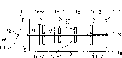
Fig. 1 is the stereogram of first embodiment of the invention;
Fig. 2 also is the stereogram of first embodiment of the invention, wherein has a ultrasonic horn to be connected in the solder case;
Fig. 3 cuts open the cutaway view of getting along the line A-A among Fig. 2;
Fig. 4 is the plane of second embodiment of the invention;
Fig. 5 is the plane of third embodiment of the invention;
Fig. 6 shows the fourth embodiment of the present invention, and wherein scheming A is a cutaway view, and figure B is a plane;
Fig. 7 cuts open the cutaway view of getting along the line A-A among Fig. 8, shows the fifth embodiment of the present invention;
Fig. 8 is the stereogram of fifth embodiment of the invention;
Fig. 9 is the exploded perspective view of the key component of fifth embodiment of the invention;
Figure 10 is a schematic diagram, shows the relation between resonator, oscillator and the ultrasonic vibration waveform of fifth embodiment of the invention;
Figure 11 cuts open the cutaway view of getting along the line B-B among Figure 12, shows the sixth embodiment of the present invention;
Figure 12 is the stereogram of sixth embodiment of the invention;
Figure 13 is the profile of seventh embodiment of the invention;
Figure 14 is a schematic diagram, shows the relation between resonator, oscillator and the ultrasonic vibration waveform of eighth embodiment of the invention;
Figure 15 is the schematic diagram according to a fin-type booster of ninth embodiment of the invention;
Figure 16 is the schematic diagram according to another fin-type booster of ninth embodiment of the invention; And
Figure 17 shows a ultrasonic horn with various grooves of prior art, and wherein scheming A is plane, and figure B to D cuts open the cutaway view of getting along the line A-A among the figure A.
Fig. 1 to Fig. 3 shows the first embodiment of the present invention.At first, in Fig. 1, ultrasonic horn 1-1 has one and forms rectangle or quadrangle horn main body 1-1a square and that made by titanium alloy and so on alloy.In this embodiment, horn main body 1-1a is long in side direction, and is the direction of propagation of ultrasonic vibration by the horizontal L of single-point line expression, and its length equals from maximum amplitude points f1 to next maximum amplitude points f3, and promptly 1/2 of the resonant frequency wavelength.The centre of an end face in the two opposite end faces of horn main body 1-1a is along horizontal L shaped Cheng Youyi threaded connection hole 1-1b.Two maximum amplitude points f1 between horn main body 1-1a have installed a supporting part 1-1c who is formed, is used to be connected by sheet material with the minimum amplitude point f2 place in the middle of the f3, and this coupling part is with the outside projection of the form of a straight-flanked ring.Because supporting part 1-1c projection on perpendicular to the front and rear direction of horn main body 1-1a is so this supporting part 1-1c is between a plurality of groove 1-1d and 1-1e that are formed on the horn main body 1-1a.Alphabetical A among Fig. 1 represents between near the screwed hole 1-1b inside groove 1-1d and the 1-1d and near inside groove 1-1e the screwed hole 1-1b and the Center Gap between the 1-1e, B represents horn main body 1-1a width longitudinally, C represents that the end face of groove 1-1d and 1-1e and horn main body 1-1a is along horizontal interval, E is the width of groove 1-1d and 1-1e, D be two adjacent groove 1-1d and 1-1e along horn main body 1-1a longitudinally at interval and the end face interval in the vertical of water jacket 1-1d and 1-1e and horn main body 1-1a, and F is the end face interval longitudinally of supporting part 1-1c and horn main body 1-1a.In above-mentioned structure, supporting part 1-1c and horn main body part 1-1a are that formation is as a whole.
In Fig. 2 and Fig. 3, ultrasonic horn 1-1 is installed on the solder case 1-3, oscillator 1-2 is by the piezoelectric element that electric energy is converted to mechanical energy or electroacoustic or electric oscillation oscillator that magnetostriction element is formed, it takes place by the electric power of supplying with from supersonic generator not shown in the figures and exports the longitudinal ultrasonic ripple vibration with preset frequency, and oscillator 1-2 is by the screwed hole 1-1b that is formed in the ultrasonic horn 1-1, be formed on the unshowned screwed hole in the oscillator 1-2 and be spun on screwed hole 1-1b and not shown screwed hole in the grub screw (not shown) and be connected in ultrasonic horn 1-1.
For brazing operation, on the position that is lower than the surface of solder 1-4 in case 1-4a of solder case 1-3, be formed with a square through hole 1-3a, it is greater than the first half of horn main body 1-1a, but less than the external diameter of supporting part 1-1c.The outside at solder case 1-3 has formed a square groove part 1-3b around through hole 1-3a.Be equipped with a potted component 1-5 in the groove part 1-3b, its shape is and roughly the same square of groove part 1-3b, and be to make by the anti-solder material that is difficult to allow solder adhere to, perhaps, can seal 1-5 be installed the first half along support 1-1c around horn main body 1-1a, then, the first half of horn main body part 1-1a is inserted through hole 1-3a from the outside of solder case 1-3, and make the inside of its projection at solder case 1-3.
Simultaneously, the bearing 1-6 that ultrasonic horn 1-1 is fixed on the solder case 1-3 is a rectangle, and has the similar groove part 1-6b of groove part 1-3b of through hole 1-6a like the through hole 1-3a class people of a shape and solder case 1-3 and shape and solder case 1-3.Be equipped with the material seal 1-7 all identical in the groove part 1-6b of bearing 1-6 with seal 1-5 with shape, perhaps, can seal 1-7 be installed along the supporting part 1-1c of the latter half that centers on horn main body 1-1a, the through hole 1-6c that bolt 1-8 is passed on the bearing 1-6 screws in a plurality of screwed hole 1-3c that form around the groove part 1-3b of solder case 1-3.Thus, supporting part 1-1c can prevent that the solder between solder case 1-3 and the bearing 1-6 from leaking by seal 1-5 and 1-7, and the ultrasonic horn 1-1 that is connected in oscillator 1-2 then links on the solder case 1-3, and passes the wall of solder case 1-3.
Structure according to this embodiment, after ultrasonic horn 1-1 is connected in solder case 1-3, solder 1-4 can be injected solder case 1-3, startup is arranged on the heat that the heater (not shown) on the solder case 1-3 melts the solder in the solder case 1-3 with generation, and then the pump (not shown) that driving is arranged in the solder case 1-3 circulates solder 1-4 in solder case 1-3.The solder 1-4 that circulates can cover the first half of projection at the ultrasonic horn 1-1 of solder case 1-3 inboard, unshowned workpiece is immersed among the solder 1-4 and with ultrasonic horn 1-1 and faces mutually, by ultrasonic horn mat ultrasonic vibration being resonated, so that solder 1-4 is imposed on workpiece to oscillator 1-2 supply capability.
For this brazing operation, because be inserted with betwixt supporting part 1-1c ultrasonic horn before, be provided with a next door 1-1f between groove 1-1d on the back two halves and the 1-1e, the position in this next door is corresponding with supporting part 1-1c, even so pass the wall of solder case 1-3 when ultrasonic horn and be connected when being lower than the position on solder surface in the case on the solder case 1-3, the groove 1-1d that is in molten solder 1-4 one side also can be by next door 1-1f and isolated with the outside of solder case 1-3, and the groove 1-1e that is in no solder one side also can be by next door 1-1f and and the inboard of solder case 1-3 completely cut off.Can prevent that thus the solder 1-4 that melts from flowing to the outside through groove 1-1d and 1-1e in solder case 1-3, can improve the amplitude state of ultrasonic horn 1-1 by groove 1-1d on the forward and backward two halves that is in ultrasonic horn 1-1 and 1-1e, apply the uniform solder of thickness to workpiece and become possibility thereby make.
Fig. 4 shows the second embodiment of the present invention.Even (being provided with supporting part 1-1c therebetween) is formed with and amounts to four groove 1-1d and 1-1e on the forward and backward two halves of the horn main body 1-1a of ultrasonic horn 1-1, and be two rows about the center is arranged to screwed hole 1-1b, this embodiment also can obtain identical functions and effect, though the horizontal width that also will see horn main body 1-1a how.
Fig. 5 shows the third embodiment of the present invention.If making different sizes along the length G of vibration direction of transfer and away from the outside 1d-2 of screwed hole 1-1b and 1e-2 along the length H of vibration direction of transfer near the inside groove 1d-1 of screwed hole 1-1b and 1e-2, just can regulate the amplitude of vibrating loudspeakers 1-1, thereby can weld easily according to the shape and size of workpiece.In this embodiment, G is less than H.
Fig. 6 shows the fourth embodiment of the present invention.When groove 1-1d and 1-1e are formed on forward and backward two parts and are lower than supporting part 1-1c, and next door 1-1f is when doing thinlyyer, groove 1-1d just looks like separately not the same with 1-1e, thereby makes the amplitude state of improving ultrasonic horn 1-1 further become possibility.
Letter w is represented the waveform of the immediate movement (amplitude) of the ultrasonic vibration that caused by the resonance of ultrasonic horn 1-1 among Fig. 1, Fig. 4 and Fig. 5, and S represents the reference line (zero line) of amplitude.
Alphabetical X among Fig. 1, Fig. 3, Fig. 4 and Fig. 5 represents the direction of vibration of ultrasonic horn.
In the various embodiments described above, the situation that ultrasonic horn 1-1 is directly connected in oscillator 1-2 has been described in conjunction with the accompanying drawings.Ultrasonic horn 1-1 also can by a booster and and oscillator 1-2 co-axial interconnect, booster links to each other with ultrasonic horn 1-1 with screwed hole by grub screw, oscillator 1-2 also is connected in booster (all not shown among the figure) by grub screw and screwed hole, so also can obtain effect same as the previously described embodiments.In this case, the quantity of booster can be one or more.
Fig. 7 and Fig. 8 show the fifth embodiment of the present invention.From these two accompanying drawings, can see, the shape of solder case 1 is similar to a bathtub, it has a top of opening that is used for injecting molten solder 2, and a mat separating element 3 and be formed on circulation channel 4 in the solder case 2, the two ends of described separating element are connected in the left and right sidewall 1a and the 1b of solder case 1.The heater 7 of having settled pump 6 and being in pump 6 upstreams in the circulation channel 4 between the diapire 1c of the following next door 3a of separating element 3 and solder case 1.The solder 2 that is injected into solder case 1 is melted by heater 7, and the solder 2 of fusion can be by pump 6 circulation on the direction shown in the arrow.
In this embodiment, upwards flow to by the solder 2 of the pump 6 pumpings circulation channel 4 between the diapire 1c of next door 3a and solder case 1 down the circulation channel 4 between the antetheca 1d of antetheca 3b and solder case, and through behind the last next door 3c, liquid level along the solder 2 of rear partition wall 3d in falling into solder case 1, then flow through the rear end part of following next door 3a and return circulation channel 4 between the diapire 1c of next door 3a and solder case 1 down, and sucked by pump 6 there.
As shown in Figure 9, the antetheca 1d that is located at solder case 1 goes up and the receiving portions 8 that constitute circulation channel 4 parts have a hole 8b who extends to overhang 8a from antetheca 1d, and described overhang 8a outwards protrudes out from the outer surface of antetheca 1d.Overhang 8a and solder case 1 separately form, and it is connected in the antetheca 1d of solder case 1 by screw connection, welding or similar approach.Hole 8b has the square-section, and this square-section is similar to and greater than the first half 14b of the supporting part 14a front that is in resonator 14 (hereinafter will describe in detail), described hole is communicated with the inside and outside both sides of solder case 1.Be formed with a hole 8c who becomes stepped and coaxial distribution greater than hole 8b, with hole 8b in the place ahead of hole 8b, formed a cascaded surface 8d between hole 8c and the hole 8b, the supporting part 14a of cascaded surface 8d receivability resonator 14 as closed-loop.On the front end face of overhang 8a, be provided with a plurality of at the screwed hole 8e that upwards is equidistant intervals week around hole 8c.
Cooperate the Press fitting 11 resonator 14 is remained in the solder case 1 to have a window 11a with receiving portion 8, the shape of this window is similar to and greater than the latter half 14c that is in the supporting part 14a back in the middle of the resonator 14.Be provided with a fin 11b that can fit into the closed ring of hole 8c around window 11a on the rear end face of Press fitting 11.Around the fin of Press fitting 11 and with the corresponding position of the screwed hole of receiving portion 8 on be formed with the perforation 11c that is used for admitting screw 12.
In this embodiment, as shown in figure 10, resonator 14 forms shaft-like and by the alloy of the preferable acoustic properties of tool, for example titanium alloy is made, and itself also is an energy applies ultrasonic vibration to molten solder 2 a ultrasonic horn.In addition, see over from the direction of oscillator 13, prism of its outer appearance, its length equals 1/2 wavelength (arriving next maximum amplitude points f3 through nodal point f2 from maximum amplitude points f1).The middle body of the end face of the latter half 14c of resonator 14 is connected in the output of oscillator 13, oscillator 14 also have one at nodal point f2 place the closed ring overhang 14a from the outside projection of outer peripheral face.
For resonator 14 is connected in solder case 1, on the latter half 14c of resonator 14, assembled seal 10 and Press fitting 11, and oscillator 3 is connected in resonator 14.Another seal 9 is assemblied on the first half 14b of resonator 14, pump 6 and heater 7 in being located at solder case 1 are not worked, when preferably not having solder in the solder case 1, the first half 14b of resonator 14 outside patchhole 8b behind the 8c of hole from solder case 1 can be made the inboard projection of the fore-end of resonator 14 to solder case 1.Subsequently, the window 11a of Press fitting 11 is assembled on the latter half 14c of resonator 14, screw 12 passes the through hole 11c on the Press fitting 11 and matches with the screwed hole 8e spiral of receiving portion 8, thereby but the fin 11b of mat Press fitting 11 supporting part 14a and seal 9 and 10 are pressed against on the admittance face 8d.Seal 9 and 10 is because of the compression that is subjected to fin 11b, admittance face 8d and supporting part 14a has had certain back stretch, and supporting part 14a keeps by receiving portion 8, Press fitting 11 and seal g and 10.Like this, resonator 14 just can be fixed in the solder case 1.In the time will being fixed on Press fitting 11 in the receiving portion 8, the first half 14b of resonator 14 and latter half 14c be hole 8b with receiving portion 8 with the coaxial setting of hole 8c but do not contact, screw 12 has played fastening effect.
Simultaneously, work-supporting means 15 has a base portion 15a and a 15b of bar portion, and described base portion extends forward from the top of the rear wall 1e of solder case 1, and an end of described bar portion is connected in base portion 15a rotationally.The length that is assemblied in the clamping limb 15d in the slotted hole 15c of end parts before the 15b of bar portion slidably is: from a pair of forward and backward stop part 15e and 15f (they are that left wall 1a from solder case 1 extends to right wall 1b), through the antetheca 1d of solder case 1 and the space between the base portion 15a, the circulation channel 4 between antetheca 1d and separating element 3.This clamping limb 15d has a retained part 15g who is used for holding workpiece 16, and workpiece setting is in the end of clamping limb 15d, and it suspends in midair to carry out soldering from retained part.The mid portion of the 15b of bar portion is connected in the piston rod 15j of cylinder 15i rotationally, and cylinder 15i then is connected in the pillar 15h that vertically is installed on the base portion 15a rotationally.
When cylinder 15i shrinks, piston rod 15j can make the 15b of bar portion lift, the 15b of bar portion is around itself and upwards rotation of the tie point 15k of base portion 15a, so, clamping limb 15d just can slide in slotted hole 15c under the guiding of stop part 15e and 15f and move upward, so just can be by pulling the interior molten solder 2 of the workpiece 16 of the retained part 15g clamping circulation channel 4 between antetheca 1d and separating element 3.If cylinder 15i stretches when workpiece 16 pulls, piston rod 15j moves downward the 15b of bar portion, the 15b of bar portion rotates around tie point 15k, so, clamping limb 15d just can slide in slotted hole 15c under the guiding of stop part 15e and 15f, so just can immerse the workpiece 16 by retained part 15g clamping the molten solder 2 in the circulation channel 4 between antetheca 1d and the separating element 3, this workpiece overhangs and faces mutually with the front end face of resonator 14 is spaced apart from retained part.
Structure according to the foregoing description, because receiving portion 8 has certain diameter poor at the hole 8b of solder case 1 one sides with at the hole of opposite side 8c, so just there has been one to admit face 8d, thereby when the first half of resonator 14 from the outside of solder case 1 during through via hole 8c patchhole 8b, the fin 11b that is assemblied in the Press fitting 11 on the latter half 14c of resonator 14 will assemble hand-hole 8c, resonator 14 is to be arranged to discord hole 8b to contact with window 11a, and being mat screws 12, Press fitting 11 is anchored on receiving portion 8, seal 9 and 10 is subjected to fin 11b, the supporting part 14a of resonator 14 and admit the compression of face 8d and put aside the elastic force of answer simultaneously, the supporting part 14a of resonator 14 are kept by receiving portion 8 and the Press fitting 11 that is fastened on the receiving portion 8.So just resonator can be fixed in the solder case 1 suitably.In this state, resonator 14 is mats at the supporting part 14a of the outside projection in nodal point f2 place and remains in the solder case 1, the first half 14b of resonator 14 and latter half 14c are connected in solder case 1 like this, that is, their discord solder casees 1, receiving portion 8 contact with Press fitting 11.Therefore, make it to produce vertical ultrasonic vibration when providing electric power and when making resonator 14 resonance, the energy efficient of ultrasonic vibration can be delivered to the front end face of resonator 14 to oscillator 13.
Particularly, structure according to this embodiment, because hole 8b and hole 8c in the receiving portion 8 are provided with mutually coaxially, and on Press fitting 11, be formed with fin 11b among the hole 8c that can be assemblied in receiving portion 8, so when fin 11b be inserted into hole 8c and Press fitting 11 by screw 12 fastening slightly the time, resonator 14 vertically can be moved with horizontal direction, so that formed the space of a closed-loop shape between the window 11a of the latter half 14c of resonator 14 and Press fitting 11, the first half 14b and the latter half 14c that so just can determine to be placed in the resonator 14 in the solder case 1 easily are discord solder casees 1, receiving portion 8 and Press fitting 11 contacts.
In addition, structure according to this embodiment, because a plurality of screwed hole 8e of receiving portion 8 and a plurality of through hole 11c of Press fitting 11 are equidistant intervals, so, the survey tool of clearance gauge and so on comes holding screw 12 circumferentially to form a roughly uniform space near the front end face of the receiving portion the screwed hole 8e 8 with on edge between near the rear end face of the Press fitting the through hole 11c 11 fastening force on the supporting part 14a that Press fitting 11 is fastened to resonator 14 is become evenly by for example adopting, thereby can reduce the energy loss that puts on the ultrasonic vibration of solder 2 and workpiece 16 from resonator 14 further.
On the other hand, in this embodiment, when solder injects solder case 1, heater starting is so that the solder melted by heat in the solder case 1, pump 6 also is driven so that solder 2 circulation in solder case 1, workpiece 16 by retained part 15 clampings is parked on the upper limit position of work-supporting means 15, retained part 15 moves down and workpiece 16 is immersed in the solder 2 (as shown in Figure 7) and makes workpiece 16 in the face of resonator 14, resonator 14 can with resonate by oscillator 13 being applied the longitudinal ultrasonic ripple vibration that electric power produces, this longitudinal ultrasonic ripple vibration imposes on workpiece 16 from resonator 14 and through solder 2, the solder 2 of fusion can correctly stick to workpiece 16 and need on the part of soldering, through after the preset time, the retained part 15g of work-supporting means 15 begins to move upward, so that workpiece 16 is pulled out from solder 2.Stick to after solder 2 on the workpiece 16 solidifies, workpiece 16 is lifted down from retained part 15, so just finished one solder 2 is applied to work period on the workpiece 16.
Figure 11 and 12 shows the sixth embodiment of the present invention.This embodiment is characterised in that, its structure is suitable for the sort of brazing operation that whole work-piece can not be immersed in the molten solder 2, for example, when solder is imposed on the lead of an electronics or electrical equipment, or when mat solder 2 the wire bonds of a potted element during in the electric conductor of printed circuit board (PCB).In Figure 11 and Figure 12, solder case 20 is to form the shape of a box so that hold the solder 2 of fusion, that solder case 20 has is one that will be described in more detail below, be formed on working hole 20b (it is to represent with imaginary line in Figure 12) on the roof 20a, that allow workpiece 22 turnover, and the make progress inner core 20d of projection of a diapire 20c from solder case 20.The upper end of inner core 20d is under roof 20a and stand away, and its occupied plane is greater than working hole 20b.On the position that is lower than its upper end of inner core 20d, be provided with a next door 20e.Next door 20e has formed a work box 20f, and it has an open top holds predetermined quantity with the top at inner core 20d molten solder 2.The bottom of work box 20f is provided with a pump 6, and a suction inlet 20g who is communicated with the inlet of pump 6.The place that the bottom of solder case 20 is lower than the next door 20e of work box 20f is formed with an apotheca 20h, the coaxial resonator 14 that is connected in the output of oscillator 13 in order to store mat screwed hole and screw (not shown).
Be formed with receiving portion 8 in the 20e of next door, resonator 14 is fixed in this receiving portion by Press fitting 11.In other words, seal 10 and Press fitting 11 are to be assemblied on the latter half 14c of oscillator 14, and oscillator 13 is connected in resonator 14, and another seal 9 then is assemblied on the first half 14b of resonator 14.Then,, through the hole 8c of receiving portion 8 the first half 14b of resonator 14 is inserted among the 8b of hole from the outside of apotheca 20h, and keep not contacting, at this moment, do not have solder 2 among the work box 20f of solder case 20, therefore the top projection of resonator 14 is advanced within the work box 20f.Subsequently, under not contacted situation, the window 11a of Press fitting 11 is assembled on the latter half 14c of resonator 14, thereby and the screwed hole 8e that makes screw 12 via through holes 11c screw in receiving portion 8 is fixed to Press fitting 11 on the receiving portion 8, therefore, resonator 14 is to be connected in solder case 20 in such a way, promptly, it is to be kept by receiving portion 8, Press fitting 11 and seal 9 and 10, and seal 9 and 10 is compressed and has put aside the elastic force of replying.
In solder case 20, formed a circulation channel 21 by the inner core 20d of perisporium 20i, diapire 20c and solder case 20.Be provided with a heater 7 in the circulation channel 21, the work by heater 7 can make solders 2 fusings of injecting in the solder case 20, and on the direction shown in the arrow of the driving lower edge of pump 6 circulation.In this embodiment, between the inner core 20d of solder case 20 and the circulation channel 21 between the diapire 20c, the suction inlet 20g that flows through accumulates in the work box 20f at last by the solder 2 of pump 6 discharging.The solder 2 that overflows from work box 20f can on inner core 20d, hold around enter the liquid level of solder 2, return circulation channel 21 then and suck from suction inlet 20g by pump 6.
Structure according to this embodiment, when molten solder 2 in Figure 11 on the direction shown in the arrow during circulation, the liquid level of solder 2 can rise from work box 20f because of capillary effect, and be rendered as minute surface, resonator 14 can produce resonance with the longitudinal ultrasonic ripple vibration by oscillator 13 supply capabilities are produced.Solder 2 can be applied in to the lead 22a of electronics shown in the imaginary line among Figure 11 or electrical equipment 22 (for example part of a workpiece), promptly, workpiece from the working hole 20b of the solder case 20 tops solder case 20 of packing into, is immersed in the lead 22a of electronics or electrical equipment 22 in the solder 2 among the work box 20f and it is faced mutually with resonator 14.
Though do not illustrate in this embodiment, but can also be arranged in the solder case 20 or come clamping electronics or electrical equipment 22 by one, so that solder 2 is imposed on the lead 22a of electronics or electrical equipment 22 with work-supporting means that the solder case was arranged in 20 minutes.
Figure 13 shows the seventh embodiment of the present invention.In this accompanying drawing, solder case 30 is a bathtub shapes, and it has: a top of opening is so that hold the solder 2 of fusion; One be embedded among its diapire 30a, be used for heating and melting the heater 31 of solder 2; An and receiving portion 32 that is among the diapire 30a.Receiving portion 32 has one from the hole 32b of diapire 30a to overhang 32a extension, and described overhang protrudes out outside the lateral of diapire 30a.The hole 32b that is in the front (upside among Figure 13) of the supporting part 33a of resonator 33 has one and is similar to and greater than the circular cross-section of first half 33b, this hole is communicated with the inside and outside both sides of solder case 30.Formed a hole 32c who has negative thread in the overhang 32a of hole 32b one side with hole 32b, the cascaded surface that is the closed-loop shape between hole 32c and the hole 32b can be used as the admittance face 32d of the supporting part 33a that is used for admitting resonator 33 coaxial, steppedly.On an outer peripheral face that is used for resonator 33 being remained on the Press fitting 34 in the solder case 30, have with receiving portion 32 can with the negative thread spiral mating male threads of hole 32c, have the instrument that does not form pin thread on the rear end part of outer peripheral face and connect and join part 34a.Central authorities at Press fitting 34 have formed a window 34b, and it has a circular cross-section, and this cross section is similar to and greater than the latter half 33c of the supporting part 33a back that is in resonator 33.Seal 35 and 36 is that for example fluorine resin or polytetrafluoroethylene (PTFE) are made, and have the closed-loop shape that roughly is similar to admittance face 32d by the material that is difficult to adhere to molten solder 2.
Structure according to this embodiment, seal 35 and 36 is assemblied in respectively on the first half 33b and latter half 33c of resonator 33, when not having solder 2 in the solder case 30, can be with the first half 33b of resonator 33 from the outside of solder case 30 through hole 32c patchhole 32b, the top projection of resonator 33 protrudes out in the inside of solder case 30 and keeps not contacting, the window 34b of Press fitting 34 is assembled on the latter half 33c of resonator 33, by the cooperation of pin thread and negative thread and Press fitting 34 is assembled among the hole 32c of receiving portion 32, the instrument that is inserted into Press fitting 34 with the instrument of spanner and so on connects joins part 34a, Press fitting 34 is fastened on the receiving portion 32, so, can pass through receiving portion 32, Press fitting 34 and seal 35 and 36 come the supporting part 33a of clamping resonator 33.So just resonator 33 can be fixed in the solder case 30.
In this state, solder 2 is injected solder case 30, start heater 31 so that solder 2 melted by heat, make resonator 33 and resonate by the longitudinal ultrasonic ripple vibration that unshowned oscillator supply capability is produced, described oscillator is engaged in the screw in the screwed hole by the screwed hole that do not illustrate and spiral and is connected in the latter half 33c of resonator 33 coaxially, one workpiece (not shown) is immersed molten solder 2 from solder case 30 tops, so just can impose on workpiece to solder 2.Therefore, this embodiment can provide a kind of ultrasonic vibration soldering apparatus simple in structure, and it is suitable for the production of small lot, and solder 2 is not circulated.
In the 5th to the 7th above-mentioned embodiment, because be provided with seal 9,10,35 and 36 at the supporting part 14a of resonator 14 and 33 and the both sides of 33a, even so when the surface tension of fusing and solder 2 under the high temperature of in 230 to 300 ℃ of solders 2 descends, can prevent that also solder 2 from leaking on the contact-making surface between the contact-making surface between receiving portion 8 and the supporting part 14a and Press fitting 11 and the supporting part 14a.Yet, when lower and surface tension is higher when the fusion temperature of solder 2, even without seal 9,10,35 and 36, can prevent that also solder 2 from leaking on the contact-making surface between the contact-making surface between receiving portion 8 and the supporting part 14a and Press fitting 11 and the supporting part 14a, but this to see the fusion temperature of solder 2 and decide.
Figure 14 shows the eighth embodiment of the present invention.In this accompanying drawing, resonator 40 be with first to the 3rd embodiment in resonator 14 and 33 equivalences, it comprises: one forms ultrasonic horn 41 shaft-like, that made by the alloy of for example titanium alloy and so on; One shaft-like booster 42, it is by screwed hole and screw (not shown) and coaxial ultrasonic horn 41 1 ends that are connected, and is to be made by for example material of titanium, aluminium or hard cast iron and so on; And a shaft-like fin-type booster 43, it is by screwed hole and screw (not shown) and a coaxial end that is connected booster 42, and be by the tool high thermal conductivity can material make aluminium for example.One end of fin-type booster 43 is by screwed hole and the coaxial output that is connected in oscillator 44 of screw (not shown), oscillator 44 be with the 5th to the 7th embodiment in oscillator 13 equivalences.From oscillator 44, the length of fin-type booster 43 equals 1/2 wavelength (arriving next maximum amplitude points f13 through nodal point f12 from maximum amplitude points f11), the length of booster 42 equals 1/2 wavelength (arriving next maximum amplitude points f15 through nodal point f14 from maximum amplitude points f13), and the length of ultrasonic horn 41 equals 1/2 wavelength (arriving next maximum amplitude points f17 through nodal point f16 from maximum amplitude points f15).At nodal point f16 place, on the outer peripheral face of ultrasonic horn 41, be provided with the supporting part 41a of a closed-loop shape.Each output of booster 42, fin-type booster 43 and oscillator 44 is provided with groove part 42a, 42b, 43a, 43b and 44a, connects or throw off the work that connects on its outer surface to be used for accepting unshowned instrument.Fin-type booster 43 is to form with the cutting of aluminium bar, has the groove 43c of the circumferential equidistant intervals in a plurality of edges on its outer peripheral face, and has preferable radiation (heat) character.
Structure according to this embodiment, when by receiving portion 8 or 32 and Press fitting 11 or 34 come the supporting part 41a of the ultrasonic horn 41 of clamping resonator 40, and be fixed in solder case 1, in 20 or 30 when carrying out brazing operation with the resonator 14 of the 5th to the 7th embodiment or 33 similar modes, from molten solder 2, through ultrasonic horn 41 and booster 42 and be delivered to the heat of fin-type booster 43 can be by fin-type booster 43 (material by the preferable radiance of tool is made) to external radiation, almost can not be delivered to oscillator 44, thereby can prevent that oscillator 44 is heated.
Owing on the outer peripheral face of fin-type booster 43, longitudinally be provided with a plurality of fins, and between adjacent fin, formed groove 43c, so the area of radiation has increased.Therefore, can further improve the radiative property of fin-type booster 43.
Because fin-type booster 43 circumferentially on equidistant compartment of terrain be provided with a plurality of groove 43c, the degree of depth of groove 43c is all identical with length, thereby the center of gravity of fin-type booster 43 is to overlap with the geometric center of fin-type booster 43, so fin-type booster 43 can be delivered to booster 42 to ultrasonic vibration from oscillator 44 effectively.
Figure 15 and Figure 16 show and the different fin-type booster of above-mentioned fin-type booster.Fin-type booster 43A shown in Figure 15 has the groove 43d of the circumferential equidistant intervals in a plurality of edges, and they have the identical degree of depth and are formed into the two ends of fin-type booster 43A always.On the core of the both ends of the surface of fin-type booster 43A, be provided with the screwed hole 43e and the 43f of desired depth.As shown in figure 14, oscillator 44 mat screwed hole 43e and be connected in fin-type booster 43A, booster 42 or ultrasonic horn 41 are to be connected in fin-type booster 43A by another screwed hole 43f.
Fin-type booster 43B shown in Figure 16 has the circumferentially groove 43g of equidistant intervals of a plurality of deep equalities, edge, and the quantity of groove 43g and the degree of depth are all greater than fin-type booster 43A shown in Figure 15, so that further improve thermal-radiating character.The both ends of the surface of fin-type booster 43B are provided with two overhang 43h and 43i, they have the outer peripheral face that contacts with the semicircle bottom of groove 43g, have formed respectively in the end face of described overhang 43h and 43i and screwed hole 43e shown in Figure 15 and similar screwed hole 43j of 43f and 43k.
Claims (3)
1. ultrasonic vibration soldering apparatus that is used for welding work pieces, it applies ultrasonic vibration by a resonator to the molten solder in the solder case, and described resonator is connected in one can produce the oscillator of the longitudinal ultrasonic ripple vibration of preset frequency, and described device comprises:
One is arranged on the nodal point place of described ultrasonic vibration and the supporting part that outwards protrudes out; It is characterized in that this device also comprises:
One is arranged on the receiving portion on the described solder case, this receiving portion has an admittance face, admittance face be arranged on a diameter greater than described resonator external diameter but less than the through hole of described supporting part diameter and a diameter greater than the described supporting part of described resonator and with the coaxial shrinkage pool of described through hole between;
One is used for described supporting part is pressed against the Press fitting of described admittance face;
Be used for described Press fitting is attached to the fastener of described receiving portion, so as to described supporting part being folded between described Press fitting and the described admittance face, thereby described resonator is attached to described solder case, get along well described solder case, described receiving portion and described Press fitting of described resonator contacts, thereby makes the energy transmission maximization of described ultrasonic vibration.
2. device as claimed in claim 1 is characterized in that, is provided with groove at the front side and the rear side of the described supporting part of described resonator, and described supporting part can be used as a border, uses the solder that prevents described fusion and leaks from described groove.
3. device as claimed in claim 1 is characterized in that, described device also comprises a fin-type booster, and this booster is to make with Heat Conduction Material, and is folded between described ultrasonic horn and the described oscillator, thereby makes the heat radiation maximum of described resonator.
Applications Claiming Priority (2)
| Application Number | Priority Date | Filing Date | Title |
|---|---|---|---|
| JP8170083A JP2875211B2 (en) | 1996-06-28 | 1996-06-28 | Ultrasonic horn for soldering |
| JP170083/96 | 1996-06-28 |
Publications (2)
| Publication Number | Publication Date |
|---|---|
| CN1169897A CN1169897A (en) | 1998-01-14 |
| CN1082861C true CN1082861C (en) | 2002-04-17 |
Family
ID=15898336
Family Applications (1)
| Application Number | Title | Priority Date | Filing Date |
|---|---|---|---|
| CN97112970A Expired - Fee Related CN1082861C (en) | 1996-06-28 | 1997-06-09 | Ultrasonic vibration soldering apparatus and resonator used therein |
Country Status (8)
| Country | Link |
|---|---|
| US (1) | US5884833A (en) |
| EP (1) | EP0816000B1 (en) |
| JP (1) | JP2875211B2 (en) |
| KR (1) | KR100238805B1 (en) |
| CN (1) | CN1082861C (en) |
| CA (1) | CA2204308C (en) |
| DE (1) | DE69723922T2 (en) |
| TW (1) | TW362054B (en) |
Cited By (1)
| Publication number | Priority date | Publication date | Assignee | Title |
|---|---|---|---|---|
| CN108602092A (en) * | 2015-12-04 | 2018-09-28 | 株式会社新川 | Wave welding head of ultrasonic wave |
Families Citing this family (13)
| Publication number | Priority date | Publication date | Assignee | Title |
|---|---|---|---|---|
| KR100387740B1 (en) * | 1998-03-04 | 2003-11-10 | 미시마 다이지 | Ultrasonic Welding Device |
| EP1010492B1 (en) * | 1998-12-10 | 2004-09-01 | Ultex Corporation | Ultrasonic vibration bonding method |
| JP3290632B2 (en) * | 1999-01-06 | 2002-06-10 | 株式会社アルテクス | Ultrasonic vibration bonding equipment |
| JP3568496B2 (en) * | 2001-07-06 | 2004-09-22 | 株式会社アルテクス | Ultrasonic wire bonding resonator |
| JP4249689B2 (en) | 2003-11-25 | 2009-04-02 | Necライティング株式会社 | External electrode type discharge lamp and manufacturing method thereof |
| US7439654B2 (en) * | 2004-02-24 | 2008-10-21 | Air Products And Chemicals, Inc. | Transmission of ultrasonic energy into pressurized fluids |
| DE102004019546A1 (en) * | 2004-04-22 | 2005-11-17 | Volker Gallatz | Method and device for coating an object |
| KR100906188B1 (en) * | 2007-04-11 | 2009-07-03 | 디피씨(주) | Aluminium coil with ultrasonic soldering and method for producing the same |
| JP5097038B2 (en) * | 2008-07-10 | 2012-12-12 | 株式会社日立製作所 | Soldering method and soldering apparatus |
| US20110174347A1 (en) * | 2010-01-15 | 2011-07-21 | Ultex Corporation | Resonator for ultrasonic machining and ultrasonic machining equipment |
| CN102059422A (en) * | 2010-12-10 | 2011-05-18 | 哈尔滨工业大学 | Electrical contact welding method |
| CN103394783B (en) * | 2013-07-30 | 2015-09-30 | 哈尔滨工业大学(威海) | Ultrasonic auxiliary vacuum brazing equipment |
| DE102016116430A1 (en) * | 2016-09-02 | 2018-03-08 | Herrmann Ultraschalltechnik Gmbh & Co. Kg | Ultrasonic vibration system |
Citations (3)
| Publication number | Priority date | Publication date | Assignee | Title |
|---|---|---|---|---|
| US3752381A (en) * | 1972-03-17 | 1973-08-14 | Branson Instr | Ultrasonic soldering apparatus |
| DE2231908A1 (en) * | 1972-06-29 | 1974-01-10 | Siemens Ag | Soldering leads on components - using molten solder and ultrasonic energy |
| US3934781A (en) * | 1973-09-18 | 1976-01-27 | Siemens Aktiengesellschaft | Soldering bath for fluxless ultrasonic soldering |
Family Cites Families (5)
| Publication number | Priority date | Publication date | Assignee | Title |
|---|---|---|---|---|
| DE2017862B2 (en) * | 1970-04-14 | 1972-02-03 | Siemens AG, 1000 Berlin u. 8000 München | FLUX-FREE TINNING OF THE LOET BATH |
| US3945618A (en) * | 1974-08-01 | 1976-03-23 | Branson Ultrasonics Corporation | Sonic apparatus |
| DE2728634C2 (en) * | 1977-06-24 | 1979-03-08 | Siemens Ag, 1000 Berlin Und 8000 Muenchen | Ultrasonic solder bath with a sonotrode arranged with a solder bath container |
| FR2547225A1 (en) * | 1983-06-09 | 1984-12-14 | Mecasonic Sa | Ultrasonic welding sonotrode |
| DE4432402C2 (en) * | 1994-08-30 | 1998-07-02 | Ersa Loettechnik Gmbh | Wave soldering nozzle for flux-free soldering |
-
1996
- 1996-06-28 JP JP8170083A patent/JP2875211B2/en not_active Expired - Fee Related
-
1997
- 1997-04-17 US US08/839,318 patent/US5884833A/en not_active Expired - Lifetime
- 1997-04-18 EP EP97106461A patent/EP0816000B1/en not_active Expired - Lifetime
- 1997-04-18 DE DE69723922T patent/DE69723922T2/en not_active Expired - Fee Related
- 1997-04-19 TW TW086105095A patent/TW362054B/en active
- 1997-05-02 CA CA002204308A patent/CA2204308C/en not_active Expired - Fee Related
- 1997-06-09 CN CN97112970A patent/CN1082861C/en not_active Expired - Fee Related
- 1997-06-25 KR KR1019970027357A patent/KR100238805B1/en not_active IP Right Cessation
Patent Citations (3)
| Publication number | Priority date | Publication date | Assignee | Title |
|---|---|---|---|---|
| US3752381A (en) * | 1972-03-17 | 1973-08-14 | Branson Instr | Ultrasonic soldering apparatus |
| DE2231908A1 (en) * | 1972-06-29 | 1974-01-10 | Siemens Ag | Soldering leads on components - using molten solder and ultrasonic energy |
| US3934781A (en) * | 1973-09-18 | 1976-01-27 | Siemens Aktiengesellschaft | Soldering bath for fluxless ultrasonic soldering |
Cited By (2)
| Publication number | Priority date | Publication date | Assignee | Title |
|---|---|---|---|---|
| CN108602092A (en) * | 2015-12-04 | 2018-09-28 | 株式会社新川 | Wave welding head of ultrasonic wave |
| CN108602092B (en) * | 2015-12-04 | 2020-04-21 | 株式会社新川 | Ultrasonic welding head |
Also Published As
| Publication number | Publication date |
|---|---|
| JPH105991A (en) | 1998-01-13 |
| CA2204308C (en) | 2000-08-22 |
| US5884833A (en) | 1999-03-23 |
| TW362054B (en) | 1999-06-21 |
| DE69723922T2 (en) | 2004-08-19 |
| CA2204308A1 (en) | 1997-12-28 |
| KR980000732A (en) | 1998-03-30 |
| EP0816000A1 (en) | 1998-01-07 |
| DE69723922D1 (en) | 2003-09-11 |
| CN1169897A (en) | 1998-01-14 |
| KR100238805B1 (en) | 2000-01-15 |
| EP0816000B1 (en) | 2003-08-06 |
| JP2875211B2 (en) | 1999-03-31 |
Similar Documents
| Publication | Publication Date | Title |
|---|---|---|
| CN1082861C (en) | Ultrasonic vibration soldering apparatus and resonator used therein | |
| CN1295070C (en) | Frictionally welded thermoplastic articles having improved strength | |
| KR20000022315A (en) | Simultaneous amplitude and force profiling during ultrasonic welding of thermoplastic workpieces | |
| JP5453608B2 (en) | Heat sink and manufacturing method thereof | |
| CA2020245C (en) | Method and apparatus for joining thermoplastic parts | |
| CN214983639U (en) | Sealing and cutting device for garbage bag | |
| FR2793717A3 (en) | Guide frame for welding on cooling ribs and support plate of cooling body | |
| CN211730323U (en) | Round edge sealing machine | |
| CN104999661B (en) | A kind of laser synchronization welding procedure and device | |
| CN213560419U (en) | Auxiliary welding jig for surface mount components | |
| CN1030205A (en) | The high frequency induction welding of engineering plastics | |
| JP2003220489A (en) | Device and method for laser beam machining | |
| KR101273676B1 (en) | Portable ultrasonic metal welder | |
| JPH1168174A (en) | Thermoelectric semiconductor chip and manufacturing thermoelectric module | |
| CN216541833U (en) | New energy automobile battery compartment subassembly multi-angle cutting all-in-one | |
| CA2147038A1 (en) | Method and Apparatus for Obtaining a Plaque-Shaped Armature for a Composite Material Workpiece | |
| CN212192787U (en) | Bar fixing auxiliary device | |
| CN211889426U (en) | Synchronous back pressure type friction stir welding system | |
| CN217224533U (en) | Aluminum alloy ex-trusions high efficiency cutting device | |
| KR100466364B1 (en) | One side auto welding method by using cut wire type tamping | |
| CN213702240U (en) | High-efficient environment-friendly laser cutting device suitable for building site | |
| CN213730129U (en) | Practical welding tool | |
| CN211363520U (en) | Skylight atmosphere lamp controller welding frock | |
| CN220198590U (en) | Ultrasonic welding device for plastic structural part | |
| EP0098756A1 (en) | Floating core vibration transmission piece |
Legal Events
| Date | Code | Title | Description |
|---|---|---|---|
| C10 | Entry into substantive examination | ||
| SE01 | Entry into force of request for substantive examination | ||
| C06 | Publication | ||
| PB01 | Publication | ||
| C14 | Grant of patent or utility model | ||
| GR01 | Patent grant | ||
| C19 | Lapse of patent right due to non-payment of the annual fee | ||
| CF01 | Termination of patent right due to non-payment of annual fee |