CN108247837B - Swing type small concrete mixer - Google Patents

Swing type small concrete mixer Download PDF

Info

Publication number
CN108247837B
CN108247837B CN201711408639.3A CN201711408639A CN108247837B CN 108247837 B CN108247837 B CN 108247837B CN 201711408639 A CN201711408639 A CN 201711408639A CN 108247837 B CN108247837 B CN 108247837B
Authority
CN
China
Prior art keywords
shaft
fixedly connected
bevel gear
fixing plate
swing
Prior art date
Legal status (The legal status is an assumption and is not a legal conclusion. Google has not performed a legal analysis and makes no representation as to the accuracy of the status listed.)
Expired - Fee Related
Application number
CN201711408639.3A
Other languages
Chinese (zh)
Other versions
CN108247837A (en
Inventor
周秋伟
Current Assignee (The listed assignees may be inaccurate. Google has not performed a legal analysis and makes no representation or warranty as to the accuracy of the list.)
Yichang Yizhi building materials Co., Ltd
Original Assignee
Yichang Yizhi Building Materials Co Ltd
Priority date (The priority date is an assumption and is not a legal conclusion. Google has not performed a legal analysis and makes no representation as to the accuracy of the date listed.)
Filing date
Publication date
Application filed by Yichang Yizhi Building Materials Co Ltd filed Critical Yichang Yizhi Building Materials Co Ltd
Priority to CN201711408639.3A priority Critical patent/CN108247837B/en
Publication of CN108247837A publication Critical patent/CN108247837A/en
Application granted granted Critical
Publication of CN108247837B publication Critical patent/CN108247837B/en
Expired - Fee Related legal-status Critical Current
Anticipated expiration legal-status Critical

Links

Images

Classifications

    • BPERFORMING OPERATIONS; TRANSPORTING
    • B28WORKING CEMENT, CLAY, OR STONE
    • B28CPREPARING CLAY; PRODUCING MIXTURES CONTAINING CLAY OR CEMENTITIOUS MATERIAL, e.g. PLASTER
    • B28C5/00Apparatus or methods for producing mixtures of cement with other substances, e.g. slurries, mortars, porous or fibrous compositions
    • B28C5/08Apparatus or methods for producing mixtures of cement with other substances, e.g. slurries, mortars, porous or fibrous compositions using driven mechanical means affecting the mixing
    • B28C5/10Mixing in containers not actuated to effect the mixing
    • B28C5/12Mixing in containers not actuated to effect the mixing with stirrers sweeping through the materials, e.g. with incorporated feeding or discharging means or with oscillating stirrers
    • B28C5/16Mixing in containers not actuated to effect the mixing with stirrers sweeping through the materials, e.g. with incorporated feeding or discharging means or with oscillating stirrers the stirrers having motion about a vertical or steeply inclined axis
    • BPERFORMING OPERATIONS; TRANSPORTING
    • B28WORKING CEMENT, CLAY, OR STONE
    • B28CPREPARING CLAY; PRODUCING MIXTURES CONTAINING CLAY OR CEMENTITIOUS MATERIAL, e.g. PLASTER
    • B28C5/00Apparatus or methods for producing mixtures of cement with other substances, e.g. slurries, mortars, porous or fibrous compositions
    • B28C5/48Apparatus or methods for producing mixtures of cement with other substances, e.g. slurries, mortars, porous or fibrous compositions wherein the mixing is effected by vibrations
    • B28C5/485Apparatus or methods for producing mixtures of cement with other substances, e.g. slurries, mortars, porous or fibrous compositions wherein the mixing is effected by vibrations with reciprocating or oscillating stirrers; Stirrers therefor
    • BPERFORMING OPERATIONS; TRANSPORTING
    • B28WORKING CEMENT, CLAY, OR STONE
    • B28CPREPARING CLAY; PRODUCING MIXTURES CONTAINING CLAY OR CEMENTITIOUS MATERIAL, e.g. PLASTER
    • B28C7/00Controlling the operation of apparatus for producing mixtures of clay or cement with other substances; Supplying or proportioning the ingredients for mixing clay or cement with other substances; Discharging the mixture
    • B28C7/04Supplying or proportioning the ingredients
    • B28C7/06Supplying the solid ingredients, e.g. by means of endless conveyors or jigging conveyors
    • BPERFORMING OPERATIONS; TRANSPORTING
    • B28WORKING CEMENT, CLAY, OR STONE
    • B28CPREPARING CLAY; PRODUCING MIXTURES CONTAINING CLAY OR CEMENTITIOUS MATERIAL, e.g. PLASTER
    • B28C7/00Controlling the operation of apparatus for producing mixtures of clay or cement with other substances; Supplying or proportioning the ingredients for mixing clay or cement with other substances; Discharging the mixture
    • B28C7/04Supplying or proportioning the ingredients
    • B28C7/12Supplying or proportioning liquid ingredients
    • B28C7/126Supply means, e.g. nozzles
    • BPERFORMING OPERATIONS; TRANSPORTING
    • B28WORKING CEMENT, CLAY, OR STONE
    • B28CPREPARING CLAY; PRODUCING MIXTURES CONTAINING CLAY OR CEMENTITIOUS MATERIAL, e.g. PLASTER
    • B28C7/00Controlling the operation of apparatus for producing mixtures of clay or cement with other substances; Supplying or proportioning the ingredients for mixing clay or cement with other substances; Discharging the mixture
    • B28C7/16Discharge means, e.g. with intermediate storage of fresh concrete

Abstract

The invention discloses a swing type small concrete mixer, which comprises a base, support legs, a first motor, a driving shaft and a discharge port, wherein the left end and the right end of the upper surface of the base are respectively and fixedly connected with a left fixing plate and a right fixing plate, a mixing tank is arranged between the left fixing plate and the right fixing plate, the shaft extension end of the first motor is fixedly connected with the driving shaft, the lower end of the driving shaft extends into the mixing tank, the lower end of the driving shaft is sleeved with a driving gear, the inner wall of the mixing tank is provided with a tooth socket, the left side and the right side of the driving shaft are respectively provided with driven gears, the lower surface of the driven gear is fixedly connected with a mixing shaft, the upper surface of the base is fixedly connected with a second motor, during the mixing process, the driven gears drive the mixing shaft to revolve while transmitting automatically, the mixing rod is used for mixing concrete, the stirring tank is rocked back and forth to drive the concrete slurry to rock in the stirring tank, so that the concrete slurry is mixed more uniformly.

Description

Swing type small concrete mixer
Technical Field
The invention relates to the field of construction equipment, in particular to a swing type small concrete mixer.
Background
Concrete is a powdered hydraulic inorganic cementitious material. The concrete mixer is a machine for mixing and mixing concrete, gravel aggregate and water into a concrete mixture, mainly comprises a mixing cylinder, a feeding and discharging mechanism, a water supply system, a prime motor, a transmission mechanism, a frame, a supporting device and the like, and the existing concrete mixer is poor in mixing effect, not uniform enough in mixing, low in mixing efficiency and difficult to meet daily production requirements of people.
Disclosure of Invention
The invention aims to provide a swing type small concrete mixer to solve the problems in the background technology.
In order to achieve the purpose, the invention provides the following technical scheme:
a swing type small concrete mixer comprises a base, support legs, a first motor, a driving shaft and a discharge hole, wherein the left end and the right end of the upper surface of the base are respectively and fixedly connected with a left fixing plate and a right fixing plate, an agitator tank is arranged between the left fixing plate and the right fixing plate, the bottom of the agitator tank is suspended, the left side wall of the agitator tank is fixedly connected with a left swing shaft, the left end of the left swing shaft is rotatably connected with the left fixing plate, the right end of the agitator tank is fixedly connected with a right swing shaft, the right end of the right swing shaft is rotatably connected with the right fixing plate, the upper surface of the agitator tank is fixedly connected with a feed inlet, the right end of the feed inlet is fixedly connected with the first motor, the shaft extension end of the first motor is fixedly connected with the driving shaft, the lower end of the driving shaft extends into the agitator tank, the, driven gear and driving shaft meshing, driven gear inlays in the tooth's socket, driven gear's lower fixed surface is connected with the (mixing) shaft, the last fixed surface of base is connected with the second motor, the below of right side oscillating axle is equipped with half bevel gear, the axle extension end and the half bevel gear fixed connection of second motor, the left and right sides of half bevel gear is equipped with left bevel gear, right bevel gear respectively, left bevel gear and right bevel gear overlap respectively and establish on right oscillating axle, half bevel gear respectively with left bevel gear, right bevel gear intermittent type meshing.
As a further scheme of the invention: the lower surface of the base is fixedly connected with a supporting leg.
As a still further scheme of the invention: the central lines of the left swinging shaft and the right swinging shaft are positioned on the same straight line.
As a still further scheme of the invention: the right side of first motor is equipped with the inlet tube, inlet tube and agitator tank intercommunication install the valve on the inlet tube.
As a still further scheme of the invention: stirring rods are distributed on the stirring shaft.
As a still further scheme of the invention: the lower end of the stirring shaft is fixedly connected with a stirring blade.
As a still further scheme of the invention: the lower fixed surface of agitator tank is connected with the bin outlet, installs the valve on the bin outlet.
Compared with the prior art, the invention has the beneficial effects that: in the stirring process, the driven gear drives the stirring shaft to revolve when passing by automatically, the stirring rod is used for stirring the concrete, the stirring range is enlarged, the stirring dead angle is greatly reduced, the stirring effect is improved, the stirring efficiency is improved, and when the stirring is carried out, the stirring tank is shaken from front to back to drive the concrete slurry to shake in the stirring tank, so that the concrete slurry is mixed more uniformly, and the stirring effect is further improved.
Drawings
FIG. 1 is a schematic view of a swing type small concrete mixer;
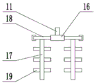
FIG. 2 is a schematic view showing the structure of a stirring shaft in the swing type small concrete mixer.
In the figure: 1-a base; 2-a leg; 3-left fixed plate; 4-right fixed plate; 5-a left oscillating shaft; 6-right oscillating shaft; 7-stirring tank; 8-a feed inlet; 9-a water inlet pipe; 10-a first electric machine; 11-a drive shaft; 12-a second electric machine; 13-half bevel gear; 14-left bevel gear; 15-right bevel gear; 16-a drive gear; 17-a stirring shaft; 18-a driven gear; 19-a stirring rod; 20-discharge opening.
Detailed Description
The technical solutions in the embodiments of the present invention will be clearly and completely described below with reference to the drawings in the embodiments of the present invention, and it is obvious that the described embodiments are only a part of the embodiments of the present invention, and not all of the embodiments. All other embodiments, which can be derived by a person skilled in the art from the embodiments given herein without making any creative effort, shall fall within the protection scope of the present invention.
Referring to fig. 1 and 2, in the embodiment of the present invention, a swing type small concrete mixer includes a base 1, a support leg 2, a first motor 10, a driving shaft 11 and a discharge port 20, the support leg 2 is fixedly connected to a lower surface of the base 1, a left fixing plate 3 and a right fixing plate 4 are respectively fixedly connected to left and right ends of an upper surface of the base 1, a mixing tank 7 is disposed between the left fixing plate 3 and the right fixing plate 4, a bottom of the mixing tank 7 is suspended, a left swing shaft 5 is fixedly connected to a left sidewall of the mixing tank 7, a left end of the left swing shaft 5 is rotatably connected to the left fixing plate 3, a right swing shaft 6 is fixedly connected to a right end of the mixing tank 7, a right end of the right swing shaft 6 is rotatably connected to the right fixing plate 4, center lines of the left swing shaft 5 and the right swing shaft 6 are located on a same straight line, the mixing tank 7 can swing back and, the right end of the feed inlet 8 is fixedly connected with a first motor 10, the right side of the first motor 10 is provided with a water inlet pipe 9, the water inlet pipe 9 is communicated with a stirring tank 7, a valve is arranged on the water inlet pipe 9, the shaft extension end of the first motor 10 is fixedly connected with a driving shaft 11, the lower end of the driving shaft 11 extends into the stirring tank 7, the lower end of the driving shaft 11 is sleeved with a driving gear 16, the inner wall of the stirring tank 7 is provided with tooth grooves, the left side and the right side of the driving shaft 11 are respectively provided with a driven gear 18, the driven gear 18 is meshed with the driving shaft 11, the driven gear 18 is embedded in the tooth grooves, the driving shaft 11 is driven to rotate when the first motor 10 runs, and then the driving gear 16 is driven to rotate, so as to drive the driven gear 18 to revolve along the tooth grooves while transmitting, the driven gear 18 drives the stirring shaft 17 to revolve while rotating, the stirring rod 19 is used for stirring concrete, the stirring range is expanded, and the stirring effect is greatly improved, the upper surface of the base 1 is fixedly connected with the second motor 12, the lower part of the right swinging shaft 6 is provided with the half bevel gear 13, the shaft extension end of the second motor 12 is fixedly connected with the half bevel gear 13, the left side and the right side of the half bevel gear 13 are respectively provided with the left bevel gear 14 and the right bevel gear 15, the left bevel gear 14 and the right bevel gear 15 are respectively sleeved on the right swinging shaft 6, the half bevel gear 13 is respectively and intermittently meshed with the left bevel gear 14 and the right bevel gear 15, the second motor 12 drives the half bevel gear 13 to rotate when in operation, when the half bevel gear 13 is meshed with the left bevel gear 14, the right swinging shaft 6 is driven to rotate, when the half bevel gear 13 is separated from the left bevel gear 14 and meshed with the right bevel gear 15, so relapse, drive right swing axle 6 just reversing to rocking around driving agitator tank 7, making the concrete thick liquid mix more evenly, further improving stirring effect, agitator tank 7's lower fixed surface is connected with bin outlet 20, installs the valve on the bin outlet 20, and the concrete thick liquid after the stirring is accomplished passes through bin outlet 20 and discharges.
It should be particularly noted that, the stirring rod in this application is the application of prior art, and revolution when the (mixing) shaft is autobiography, stirring while agitator tank back and forth swing are the innovation point of this application, and it has effectively solved the concrete mixing problem not enough even, and stirring efficiency is low.
It will be evident to those skilled in the art that the invention is not limited to the details of the foregoing illustrative embodiments, and that the present invention may be embodied in other specific forms without departing from the spirit or essential attributes thereof. The present embodiments are therefore to be considered in all respects as illustrative and not restrictive, the scope of the invention being indicated by the appended claims rather than by the foregoing description, and all changes which come within the meaning and range of equivalency of the claims are therefore intended to be embraced therein. Any reference sign in a claim should not be construed as limiting the claim concerned.
Furthermore, it should be understood that although the present description refers to embodiments, not every embodiment may contain only a single embodiment, and such description is for clarity only, and those skilled in the art should integrate the description, and the embodiments may be combined as appropriate to form other embodiments understood by those skilled in the art.

Claims (7)

1. A swing type small concrete mixer comprises a base (1), support legs (2), a first motor (10), a driving shaft (11) and a discharge hole (20), and is characterized in that the left end and the right end of the upper surface of the base (1) are respectively fixedly connected with a left fixing plate (3) and a right fixing plate (4), a mixing tank (7) is arranged between the left fixing plate (3) and the right fixing plate (4), the bottom of the mixing tank (7) is suspended, the left side wall of the mixing tank (7) is fixedly connected with a left swing shaft (5), the left end of the left swing shaft (5) is rotatably connected with the left fixing plate (3), the right end of the mixing tank (7) is fixedly connected with a right swing shaft (6), the right end of the right swing shaft (6) is rotatably connected with the right fixing plate (4), the upper surface of the mixing tank (7) is fixedly connected with a feed inlet (8), and the right end of the feed inlet (8), a driving shaft (11) is fixedly connected to the shaft extension end of a first motor (10), the lower end of the driving shaft (11) extends into a stirring tank (7), a driving gear (16) is sleeved on the lower end of the driving shaft (11), tooth grooves are formed in the inner wall of the stirring tank (7), driven gears (18) are respectively arranged on the left side and the right side of the driving shaft (11), the driven gears (18) are meshed with the driving shaft (11), the driven gears (18) are embedded in the tooth grooves, a stirring shaft (17) is fixedly connected to the lower surface of the driven gears (18), a second motor (12) is fixedly connected to the upper surface of a base (1), a half bevel gear (13) is arranged below a right swinging shaft (6), the shaft extension end of the second motor (12) is fixedly connected with the half bevel gear (13), a left bevel gear (14) and a right bevel gear (15) are respectively arranged on the left side and the right side of the half bevel gear (13), the left bevel gear (14, the half bevel gear (13) is respectively and intermittently meshed with the left bevel gear (14) and the right bevel gear (15).
2. A rocking compact concrete mixer according to claim 1, wherein the lower surface of the base (1) is fixedly connected to support legs (2).
3. A small swing-type concrete mixer according to claim 1, wherein the centre lines of said left swing shaft (5) and said right swing shaft (6) are located on the same straight line.
4. A rocking small concrete mixer according to claim 1, wherein the first motor (10) has a water inlet pipe (9) at its right side, the water inlet pipe (9) being in communication with the mixing tank (7), the water inlet pipe (9) being provided with a valve.
5. A small swing-type concrete mixer according to claim 1, wherein said mixer shaft (17) is provided with mixing bars (19).
6. A small swing type concrete mixer according to claim 1, wherein a lower end of said stirring shaft (17) is fixedly connected with a stirring blade.
7. A rocking type small concrete mixer according to claim 1, wherein a discharge opening (20) is fixedly connected to the lower surface of the mixing tank (7), and a valve is mounted on the discharge opening (20).
CN201711408639.3A 2017-12-22 2017-12-22 Swing type small concrete mixer Expired - Fee Related CN108247837B (en)

Priority Applications (1)

Application Number Priority Date Filing Date Title
CN201711408639.3A CN108247837B (en) 2017-12-22 2017-12-22 Swing type small concrete mixer

Applications Claiming Priority (1)

Application Number Priority Date Filing Date Title
CN201711408639.3A CN108247837B (en) 2017-12-22 2017-12-22 Swing type small concrete mixer

Publications (2)

Publication Number Publication Date
CN108247837A CN108247837A (en) 2018-07-06
CN108247837B true CN108247837B (en) 2020-01-24

Family

ID=62723876

Family Applications (1)

Application Number Title Priority Date Filing Date
CN201711408639.3A Expired - Fee Related CN108247837B (en) 2017-12-22 2017-12-22 Swing type small concrete mixer

Country Status (1)

Country Link
CN (1) CN108247837B (en)

Families Citing this family (6)

* Cited by examiner, † Cited by third party
Publication number Priority date Publication date Assignee Title
CN108994066A (en) * 2018-07-12 2018-12-14 蒋友裕 A kind of swing type soil remediation equipment
CN110508191A (en) * 2019-08-20 2019-11-29 杨秀英 A kind of swing Blendling-device of feedstuffs
CN111688023A (en) * 2020-06-22 2020-09-22 张桂花 Concrete mixing equipment for construction
CN112060343A (en) * 2020-07-22 2020-12-11 巢湖市永安新型建材有限责任公司 Vibration mixing arrangement of air entrainment piece raw materials
CN112227671A (en) * 2020-10-30 2021-01-15 陈进 Building mortar spraying equipment for building engineering
CN113146841A (en) * 2021-05-20 2021-07-23 苏永青 Repair concrete and preparation process thereof

Citations (3)

* Cited by examiner, † Cited by third party
Publication number Priority date Publication date Assignee Title
CN203125704U (en) * 2012-12-27 2013-08-14 长安大学 Device for swaying stirring cylinder
CN107097347A (en) * 2017-06-30 2017-08-29 应光森 A kind of swing cement mixing equipment
CN107443579A (en) * 2017-09-19 2017-12-08 无锡康斯坦特动力科技有限公司 It is a kind of to be easy to the device that concrete uniformly mixes

Patent Citations (3)

* Cited by examiner, † Cited by third party
Publication number Priority date Publication date Assignee Title
CN203125704U (en) * 2012-12-27 2013-08-14 长安大学 Device for swaying stirring cylinder
CN107097347A (en) * 2017-06-30 2017-08-29 应光森 A kind of swing cement mixing equipment
CN107443579A (en) * 2017-09-19 2017-12-08 无锡康斯坦特动力科技有限公司 It is a kind of to be easy to the device that concrete uniformly mixes

Also Published As

Publication number Publication date
CN108247837A (en) 2018-07-06

Similar Documents

Publication Publication Date Title
CN108247837B (en) Swing type small concrete mixer
CN209521085U (en) A kind of blender
CN210732829U (en) High-efficient mixer is used to concrete
CN205219421U (en) Concrete compounding agitating unit for building
CN107650266B (en) A kind of swing type small-sized cement mixer truck easy to remove
CN210789104U (en) Sand mixer
CN202805413U (en) Efficient stirring device
CN211389466U (en) Vortex type mortar mixing arrangement
CN213493128U (en) Drug feeding device for river water treatment
CN211842565U (en) Mortar mixer capable of stirring uniformly
CN210651294U (en) High-efficient concrete mixing device is used in water conservancy construction
CN209665868U (en) A kind of concrete stirring delivery pump
CN207465529U (en) A kind of high-effective concrete agitating device
CN207786379U (en) A kind of stirring apparatus
CN219132745U (en) Construction irrigation machine
CN214925672U (en) Cement mortar stirrer
CN214819615U (en) Concrete mixing device for construction
CN211729699U (en) Cement agitating unit for building
CN210905761U (en) Double-shaft humidifying stirrer
CN215094568U (en) Based on building concrete is with defeated proportioning device
CN220780167U (en) Batching agitating unit
CN215396016U (en) Concrete mixer with uniform and efficient mixing
CN220075097U (en) Gypsum board raw materials mixing arrangement
CN108312338A (en) A kind of efficient mortar blender
CN220780112U (en) Powder mixer is used in processing of bitter buckwheat tea

Legal Events

Date Code Title Description
PB01 Publication
PB01 Publication
SE01 Entry into force of request for substantive examination
TA01 Transfer of patent application right

Effective date of registration: 20191230

Address after: 443004 Jiangnan Road 99, Point Military Area, Yichang, Hubei

Applicant after: Yichang Yizhi building materials Co., Ltd

Address before: 350000 Business Floor 31, No. 6 Banzhong Road, Xindian Town, Jin'an District, Fuzhou City, Fujian Province, Taihe City Square (Phase 3), 6 Floor 1

Applicant before: Common science and Technology Development Co., Ltd.

TA01 Transfer of patent application right
GR01 Patent grant
GR01 Patent grant
CF01 Termination of patent right due to non-payment of annual fee

Granted publication date: 20200124

Termination date: 20201222

CF01 Termination of patent right due to non-payment of annual fee