CN108200552B - A V2X communication method and device - Google Patents
A V2X communication method and device Download PDFInfo
- Publication number
- CN108200552B CN108200552B CN201711340184.6A CN201711340184A CN108200552B CN 108200552 B CN108200552 B CN 108200552B CN 201711340184 A CN201711340184 A CN 201711340184A CN 108200552 B CN108200552 B CN 108200552B
- Authority
- CN
- China
- Prior art keywords
- obstacle
- bitmap
- vehicle
- unit
- state data
- Prior art date
- Legal status (The legal status is an assumption and is not a legal conclusion. Google has not performed a legal analysis and makes no representation as to the accuracy of the status listed.)
- Active
Links
Images


Classifications
-
- B—PERFORMING OPERATIONS; TRANSPORTING
- B60—VEHICLES IN GENERAL
- B60R—VEHICLES, VEHICLE FITTINGS, OR VEHICLE PARTS, NOT OTHERWISE PROVIDED FOR
- B60R16/00—Electric or fluid circuits specially adapted for vehicles and not otherwise provided for; Arrangement of elements of electric or fluid circuits specially adapted for vehicles and not otherwise provided for
- B60R16/02—Electric or fluid circuits specially adapted for vehicles and not otherwise provided for; Arrangement of elements of electric or fluid circuits specially adapted for vehicles and not otherwise provided for electric constitutive elements
-
- G—PHYSICS
- G08—SIGNALLING
- G08G—TRAFFIC CONTROL SYSTEMS
- G08G1/00—Traffic control systems for road vehicles
- G08G1/16—Anti-collision systems
- G08G1/165—Anti-collision systems for passive traffic, e.g. including static obstacles, trees
Landscapes
- Physics & Mathematics (AREA)
- General Physics & Mathematics (AREA)
- Engineering & Computer Science (AREA)
- Mechanical Engineering (AREA)
- Traffic Control Systems (AREA)
Abstract
Description
技术领域technical field
本申请涉及通信技术领域,尤其涉及一种V2X通信方法和装置。The present application relates to the field of communication technologies, and in particular, to a V2X communication method and device.
背景技术Background technique
车联万物(Vehicle to X,V2X),是未来智能交通系统(Intelligent TransportSystem,ITS)的关键技术。V2X使得车与车、车与外部基础设施之间能够通信,从而获得实时路况信息、行人信息等一系列交通信息,提高驾驶安全性、减少拥堵、提高交通效率、提供车载娱乐信息等。Vehicle to X (V2X) is the key technology of future Intelligent Transport System (ITS). V2X enables vehicle-to-vehicle, vehicle-to-vehicle and external infrastructure communication to obtain a series of traffic information such as real-time road condition information and pedestrian information, improve driving safety, reduce congestion, improve traffic efficiency, and provide in-vehicle entertainment information.
LTE-V技术基于长期演进(Long Term Evolution,LTE)技术实现车车通信,可以借助已有的蜂窝网络,运营商不需要建设专用的路侧设备(Road Side Unit,RSU)以及提供专用频谱,并能够支持大带宽、大覆盖通信,满足信息技术的应用需求。LTE-V technology is based on Long Term Evolution (LTE) technology to realize vehicle-to-vehicle communication. It can use the existing cellular network, and operators do not need to build dedicated Road Side Unit (RSU) and provide dedicated spectrum. And can support large bandwidth, large coverage communication, to meet the application requirements of information technology.
LTE-V技术无法兼容现有的公网通信模式,为了实现V2X通信,需要针对现有的LTE网络中的网元和通讯接口进行新建或修改,造成V2X通信成本昂贵。The LTE-V technology is not compatible with the existing public network communication mode. In order to realize V2X communication, it is necessary to build or modify network elements and communication interfaces in the existing LTE network, resulting in high cost of V2X communication.
发明内容SUMMARY OF THE INVENTION
本申请实施例提供一种V2X通信方法和装置,以兼容现有的公网组网实现V2X通信,降低通信成本。Embodiments of the present application provide a V2X communication method and device, which are compatible with existing public network networking to implement V2X communication and reduce communication costs.
本申请实施例提供的具体技术方案如下:The specific technical solutions provided by the embodiments of the present application are as follows:
第一方面,本申请实施例提供一种V2X通信的移动终端,包括:显示单元、融合单元、V2X计算单元,其中:所述融合单元,用于获取所述移动终端所处的车辆的状态数据和所述车辆周围的障碍物的状态数据,并根据获取到的车辆的状态数据生成第一V2X报文,以及根据获取到的障碍物的状态数据生成第一障碍物位图,将生成的所述第一V2X报文和所述第一障碍物位图发送给所述TCU服务器;所述V2X计算单元,用于接收所述TCU服务器发送的第二障碍物位图;根据所述第二障碍物位图,以及所述车辆的定位信息,生成用于所述显示单元显示的第一预警信息;其中,所述第二障碍物位图为所述TCU服务器根据所述第一V2X报文得到的障碍物位图和所述第一障碍物位图进行融合得到的障碍物位图。In a first aspect, an embodiment of the present application provides a mobile terminal for V2X communication, including: a display unit, a fusion unit, and a V2X computing unit, wherein: the fusion unit is configured to acquire status data of a vehicle where the mobile terminal is located and the state data of the obstacles around the vehicle, and generate the first V2X message according to the obtained state data of the vehicle, and generate the first obstacle bitmap according to the obtained state data of the obstacles, and the generated The first V2X message and the first obstacle bitmap are sent to the TCU server; the V2X computing unit is configured to receive the second obstacle bitmap sent by the TCU server; according to the second obstacle The material bitmap, and the positioning information of the vehicle, generate the first warning information for the display unit to display; wherein, the second obstacle bitmap is obtained by the TCU server according to the first V2X message The obstacle bitmap obtained by fusing the obstacle bitmap and the first obstacle bitmap.
采用上述方案的移动终端,能够在不改变现有公网的通信模式下,进行V2X通信,降低V2X的通信成本,进一步的,将上述移动终端应用在智能交通领域,实现车辆的危险预警,进一步实现各种智能交通业务。The mobile terminal using the above solution can carry out V2X communication without changing the communication mode of the existing public network, and reduce the communication cost of V2X. Further, the above mobile terminal is applied in the field of intelligent transportation to realize the danger warning of vehicles, and further Realize various intelligent transportation services.
一种可能的设计中,所述移动终端所处的车辆的定位信息来自定位单元,所述定位单元位于所述移动终端;或者所述定位单元位于车载T-BOX/OBD。In a possible design, the positioning information of the vehicle where the mobile terminal is located comes from a positioning unit, and the positioning unit is located in the mobile terminal; or the positioning unit is located in a vehicle-mounted T-BOX/OBD.
其中,T-BOX全称可以是Telematics BOX,中文名称可以是车载信息处理盒子,OBD全称可以是On-Board Diagnostic,中文名称可以是车载诊断系统。Among them, the full name of T-BOX can be Telematics BOX, the Chinese name can be on-board information processing box, the full name of OBD can be On-Board Diagnostic, and the Chinese name can be on-board diagnostic system.
这种设计中,在车载T-BOX/OBD不具备高精度定位能力的前提下,通过移动终端解决车载T-BOX/OBD的高精度定位问题;在车载T-BOX/OBD具备高精度定位能力的前提下,移动终端无需支持高精度定位能力,从而适用更多的移动终端型号。In this design, on the premise that the vehicle T-BOX/OBD does not have high-precision positioning capability, the high-precision positioning problem of the vehicle-mounted T-BOX/OBD is solved through the mobile terminal; the vehicle-mounted T-BOX/OBD has the high-precision positioning capability. Under the premise of , the mobile terminal does not need to support high-precision positioning capability, so it is suitable for more mobile terminal models.
一种可能的设计中,所述V2X计算单元还用于:接收所述TCU服务器发送的用于所述显示单元显示的第二预警信息,所述第二预警信息为所述TCU服务器根据所述第二障碍物位图,以及所述移动终端所处的车辆的定位信息生成的。In a possible design, the V2X computing unit is also used for: receiving the second early warning information sent by the TCU server for the display unit to display, and the second early warning information is that the TCU server is based on the The second obstacle bitmap and the positioning information of the vehicle where the mobile terminal is located are generated.
这种设计中,TCU服务器生成第二预警信息发送给移动终端进行显示,这样当移动终端由于性能限制无法实现车辆的危险预警时,能够根据第二预警信息进行危险避让,提高车辆行驶的安全系数。In this design, the TCU server generates the second warning information and sends it to the mobile terminal for display, so that when the mobile terminal cannot realize the danger warning of the vehicle due to the performance limitation, it can avoid the danger according to the second warning information and improve the safety factor of the vehicle. .
一种可能的设计中,所述融合单元用于:获取所述车辆周围的每个障碍物在对应的发现时刻的状态数据;根据每个障碍物在对应的发现时刻的状态数据,预测每个障碍物在第一时刻的状态数据,得到所述第一障碍物位图,所述第一时刻晚于所述发现时刻。In a possible design, the fusion unit is used to: obtain the state data of each obstacle around the vehicle at the corresponding discovery time; predict each obstacle according to the state data of each obstacle at the corresponding discovery time. The first obstacle bitmap is obtained from the state data of the obstacle at the first moment, and the first moment is later than the discovery moment.
这种设计中,利用车辆周围的每个障碍物在对应的发现时刻的状态数据,预测每个障碍物在第一时刻的状态数据,降低网络延时造成第一时刻对应的第一障碍物位图中指示的障碍物的位置滞后性。In this design, the state data of each obstacle around the vehicle at the corresponding discovery time is used to predict the state data of each obstacle at the first time, and the network delay is reduced to cause the first obstacle corresponding to the first time. The position hysteresis of the obstacles indicated in the figure.
一种可能的设计中,所述V2X计算单元包括综合单元和生成单元:所述综合单元,用于在第二时刻重新获取所述车辆周围的障碍物的状态数据,并根据重新获取到的障碍物的状态数据更新第一障碍物位图,所述更新后的第一障碍物位图是所述第二时刻的障碍物位图,所述第一障碍物位图为第一时刻的障碍物位图,所述第二时刻晚于所述第一时刻;将更新后的第一障碍物位图与所述第二障碍物位图进行障碍物融合得到第三障碍物位图;所述生成单元,用于根据所述第三障碍物位图,以及所述移动终端所处的车辆的定位信息,生成所述第一预警信息。In a possible design, the V2X computing unit includes a synthesis unit and a generation unit: the synthesis unit is used to re-acquire the state data of the obstacles around the vehicle at the second moment, and according to the re-acquired obstacles The state data of the object updates the first obstacle bitmap, the updated first obstacle bitmap is the obstacle bitmap at the second moment, and the first obstacle bitmap is the obstacle at the first moment bitmap, the second time is later than the first time; the updated first obstacle bitmap and the second obstacle bitmap are subjected to obstacle fusion to obtain a third obstacle bitmap; the generating The unit is configured to generate the first warning information according to the third obstacle bitmap and the positioning information of the vehicle where the mobile terminal is located.
这种设计中,移动终端根据TCU服务器发送的第二障碍物位图和自身生成的第一障碍物位图在第四时刻重新进行障碍物融合得到第三障碍物位图,这样通过综合TCU服务器和自身发现的障碍物信息,保证第三障碍物位图中指示的障碍物的准确性和有效性。In this design, the mobile terminal performs obstacle fusion again at the fourth moment according to the second obstacle bitmap sent by the TCU server and the first obstacle bitmap generated by itself to obtain the third obstacle bitmap. and the obstacle information found by itself to ensure the accuracy and validity of the obstacles indicated in the third obstacle bitmap.
一种可能的设计中,所述综合单元用于:从所述第二障碍物位图中获取所述第二障碍物位图中每个障碍物在第三时刻的状态数据,根据所述第二障碍物位图中每个障碍物在所述第三时刻的状态数据,预测所述第二障碍物位图中每个障碍物在第四时刻的状态数据得到预测后的第二障碍物位图,所述第四时刻晚于所述第三时刻;将更新后的第一障碍物位图和预测后的第二障碍物位图进行叠加;在叠加得到的障碍物位图中,将状态数据相同的至少两个障碍物合并为一个障碍物,所述至少两个障碍物为所述更新后的第一障碍物位图和所述预测后的第二障碍物位图中至少一项中的障碍物;获取经过合并处理的每个障碍物在所述第四时刻的状态数据,得到所述第三障碍物位图。In a possible design, the synthesis unit is configured to: obtain the state data of each obstacle in the second obstacle bitmap at the third moment from the second obstacle bitmap, and according to the second obstacle bitmap The state data of each obstacle in the second obstacle bitmap at the third moment, predict the state data of each obstacle in the second obstacle bitmap at the fourth moment to obtain the predicted second obstacle position Figure, the fourth time is later than the third time; the updated first obstacle bitmap and the predicted second obstacle bitmap are superimposed; in the superimposed obstacle bitmap, the state At least two obstacles with the same data are merged into one obstacle, and the at least two obstacles are in at least one of the updated first obstacle bitmap and the predicted second obstacle bitmap The obstacle; obtain the state data of each obstacle at the fourth moment that has been merged, and obtain the third obstacle bitmap.
其中,该第四时刻和该第二时刻可以是同一时刻,该第四时刻可以是将更新后的第一障碍物位图与所述第二障碍物位图进行障碍物融合的融合时刻,该第三时刻可以是该第二障碍物位图的发送时刻。Wherein, the fourth moment and the second moment may be the same moment, and the fourth moment may be the fusion moment of performing obstacle fusion on the updated first obstacle bitmap and the second obstacle bitmap, the The third moment may be the sending moment of the second obstacle bitmap.
其中,所谓的叠加是在更新后的第一障碍物位图和预测后的第二障碍物位图所在的坐标系为同一坐标系的前提下才能叠加。Wherein, the so-called superposition can only be superimposed on the premise that the coordinate system where the updated first obstacle bitmap and the predicted second obstacle bitmap are located is the same coordinate system.
其中,将更新后的第一障碍物位图和预测后的第二障碍物位图进行叠加可以包括:在第四时刻重新获取所述车辆周围的障碍物的状态数据。并根据第四时刻的该车辆周围的障碍物的状态数据,进一步更新该更新后的第一障碍物位图,得到进一步更新后的第一障碍物位图,将进一步更新后的第一障碍物位图和预测后的第二障碍物位图进行叠加。Wherein, superimposing the updated first obstacle bitmap and the predicted second obstacle bitmap may include: reacquiring state data of obstacles around the vehicle at the fourth moment. And according to the state data of the obstacles around the vehicle at the fourth moment, the updated first obstacle bitmap is further updated to obtain a further updated first obstacle bitmap, and the further updated first obstacle bitmap is obtained. The bitmap and the predicted second obstacle bitmap are superimposed.
其中,该至少两个障碍物可以是分别属于更新后的第一障碍物位图和所述预测后的第二障碍物位图中的障碍物。Wherein, the at least two obstacles may be obstacles belonging to the updated first obstacle bitmap and the predicted second obstacle bitmap respectively.
这种设计中,能够保证第三障碍物位图中不存在重复的障碍物,使第三障碍物位图中指示的障碍物更加准确。In this design, it can be ensured that there are no repeated obstacles in the third obstacle bitmap, so that the obstacles indicated in the third obstacle bitmap are more accurate.
一种可能的设计中,V2X计算单元用于:获取所述车辆的车辆行驶线,根据所述车辆行驶线和所述第二障碍物位图,以及所述车辆的定位信息,确定所述车辆与所述第二障碍物位图中指示的障碍物可能发生碰撞的危险区域,生成所述车辆的第一预警信息。In a possible design, the V2X computing unit is used to: obtain the vehicle driving line of the vehicle, and determine the vehicle according to the vehicle driving line, the second obstacle bitmap, and the positioning information of the vehicle. The first warning information of the vehicle is generated in a danger area that may collide with the obstacle indicated in the second obstacle bitmap.
一种可能的设计中,V2X计算单元用于:获取所述车辆的车辆行驶线,根据所述车辆行驶线和所述第三障碍物位图,以及所述车辆的定位信息,确定所述车辆与所述第三障碍物位图中指示的障碍物可能发生碰撞的危险区域,生成所述车辆的第一预警信息。In a possible design, the V2X computing unit is used to: obtain the vehicle driving line of the vehicle, and determine the vehicle according to the vehicle driving line, the third obstacle bitmap, and the positioning information of the vehicle. The first warning information of the vehicle is generated in a danger area that may collide with the obstacle indicated in the third obstacle bitmap.
上述设计中,给出了两种第一预警信息的生成方式,移动终端可以根据实际情形灵活选择。In the above design, two ways of generating the first warning information are given, and the mobile terminal can flexibly choose according to the actual situation.
一种可能的设计中,所述车辆的状态数据来自于:所述车辆的车载TBOX/OBD、所述TCU服务器、所述终端的采集单元、所述终端的定位单元中至少一项;所述车辆周围的障碍物的状态数据来自于:所述车辆的车载TBOX/OBD、所述TCU服务器、所述终端的采集单元、所述终端的定位单元中至少一项。In a possible design, the state data of the vehicle comes from: at least one of the on-board TBOX/OBD of the vehicle, the TCU server, the collection unit of the terminal, and the positioning unit of the terminal; the The status data of obstacles around the vehicle comes from at least one of: the on-board TBOX/OBD of the vehicle, the TCU server, the collection unit of the terminal, and the positioning unit of the terminal.
这种设计中,移动终端与车辆的车载TBOX/OBD分离,且能够采集车载TBOX/OBD、TCU服务器获取到的车辆的状态数据和障碍物的状态数据。In this design, the mobile terminal is separated from the on-board TBOX/OBD of the vehicle, and can collect the status data of the vehicle and the status data of obstacles obtained by the on-board TBOX/OBD and TCU server.
第二方面,本申请实施例提供一种TCU服务器,包括:收发单元和处理单元,所述收发单元,用于接收至少一个移动终端上报的第一V2X报文和至少一个第一障碍物位图;所述处理单元,用于根据至少一个第一V2X报文得到至少一个障碍物位图,将所述至少一个障碍物位图和所述至少一个第一障碍物位图进行障碍物融合得到的第二障碍物位图。In a second aspect, an embodiment of the present application provides a TCU server, including: a transceiver unit and a processing unit, where the transceiver unit is configured to receive a first V2X packet and at least one first obstacle bitmap reported by at least one mobile terminal ; The processing unit is used for obtaining at least one obstacle bitmap according to at least one first V2X message, and performing obstacle fusion on the at least one obstacle bitmap and the at least one first obstacle bitmap. The second obstacle bitmap.
采用上述方案,TCU服务器能够基于移动终端上报的第一V2X报文和第一障碍物位图进行障碍物融合得到第二障碍物位图,从而在不改变现有公网的通信模式下,实现各种智能交通业务,降低V2X通信的成本。With the above solution, the TCU server can perform obstacle fusion based on the first V2X message and the first obstacle bitmap reported by the mobile terminal to obtain the second obstacle bitmap, so that the communication mode of the existing public network can be realized without changing the communication mode of the existing public network. Various intelligent transportation services reduce the cost of V2X communication.
一种可能的设计中,所述收发单元还用于:获取第一移动终端所处的车辆的车辆行驶线以及所述车辆的定位信息;所述处理单元,还用于根据所述车辆行驶线和所述第二障碍物位图,以及所述车辆的定位信息,确定所述车辆与所述第二障碍物位图中指示的障碍物可能发生碰撞的危险区域,生成所述车辆的第二预警信息;所述收发单元,还用于将所述第二预警信息发送给所述第一移动终端。In a possible design, the transceiver unit is further configured to: acquire the vehicle travel line of the vehicle where the first mobile terminal is located and the positioning information of the vehicle; the processing unit is further configured to obtain the vehicle travel line according to the vehicle travel line and the second obstacle bitmap, and the positioning information of the vehicle, determine the danger area where the vehicle may collide with the obstacle indicated in the second obstacle bitmap, and generate the second obstacle map of the vehicle. Early warning information; the transceiver unit is further configured to send the second early warning information to the first mobile terminal.
这种设计中,能够利用TCU服务器生成的第二预警信息实现车辆的危险预警和避让,提高自动驾驶的安全性。In this design, the second warning information generated by the TCU server can be used to realize the danger warning and avoidance of the vehicle, and improve the safety of automatic driving.
一种可能的设计中,所述处理单元还用于:周期性更新第二障碍物位图;In a possible design, the processing unit is further configured to: periodically update the second obstacle bitmap;
所述收发单元还用于,将更新后的第二障碍物位图发送给所述第一移动终端。The transceiver unit is further configured to send the updated second obstacle bitmap to the first mobile terminal.
第三方面,本申请实施例提供一种V2X通信的方法,应用于移动终端,包括:获取所述移动终端所处的车辆的状态数据和所述车辆周围的障碍物的状态数据;根据获取到的车辆的状态数据生成第一V2X报文,以及根据获取到的障碍物的状态数据生成第一障碍物位图;将生成的所述第一V2X报文和所述第一障碍物位图发送给TCU服务器;接收所述TCU服务器发送的第二障碍物位图;根据所述第二障碍物位图,以及所述车辆的定位信息,生成用于所述显示单元显示的第一预警信息;其中,所述第二障碍物位图为所述TCU服务器根据所述第一V2X报文得到的障碍物位图和所述第一障碍物位图进行融合得到的障碍物位图。In a third aspect, an embodiment of the present application provides a V2X communication method, which is applied to a mobile terminal, including: acquiring state data of a vehicle where the mobile terminal is located and state data of obstacles around the vehicle; Generate the first V2X message according to the state data of the vehicle, and generate the first obstacle bitmap according to the obtained state data of the obstacle; send the generated first V2X message and the first obstacle bitmap To the TCU server; receive the second obstacle bitmap sent by the TCU server; generate the first warning information for the display unit to display according to the second obstacle bitmap and the positioning information of the vehicle; The second obstacle bitmap is an obstacle bitmap obtained by fusing the obstacle bitmap obtained by the TCU server according to the first V2X message and the first obstacle bitmap.
一种可能的设计中,所述移动终端所处的车辆的定位信息来自定位单元,所述定位单元位于所述移动终端;或者所述定位单元位于车载T-BOX/OBD。In a possible design, the positioning information of the vehicle where the mobile terminal is located comes from a positioning unit, and the positioning unit is located in the mobile terminal; or the positioning unit is located in a vehicle-mounted T-BOX/OBD.
一种可能的设计中,所述方法还包括:接收所述TCU服务器发送的用于所述显示单元显示的第二预警信息,所述第二预警信息为所述TCU服务器根据所述第二障碍物位图,以及所述方法所处的车辆的定位信息生成的。In a possible design, the method further includes: receiving the second warning information sent by the TCU server for the display unit to display, and the second warning information is that the TCU server is based on the second obstacle. The material level map and the positioning information of the vehicle where the method is located are generated.
一种可能的设计中,根据获取到的障碍物的状态数据生成第一障碍物位图时,可以通过以下过程实现:获取所述车辆周围的每个障碍物在对应的发现时刻的状态数据;根据每个障碍物在对应的发现时刻的状态数据,预测每个障碍物在第一时刻的状态数据,得到所述第一障碍物位图,所述第一时刻晚于所述发现时刻。In a possible design, when the first obstacle bitmap is generated according to the obtained state data of the obstacle, it can be achieved through the following process: obtaining the state data of each obstacle around the vehicle at the corresponding discovery moment; According to the state data of each obstacle at the corresponding discovery time, the state data of each obstacle at the first time is predicted, and the first obstacle bitmap is obtained, and the first time is later than the discovery time.
一种可能的设计中,根据所述第二障碍物位图,以及所述车辆的定位信息,生成用于所述显示单元显示的第一预警信息时,可以通过以下过程实现:在第二时刻重新获取所述车辆周围的障碍物的状态数据;根据根据重新获取到的障碍物的状态数据更新第一障碍物位图,所述更新后的第一障碍物位图是第二时刻的障碍物位图,所述第一障碍物位图为第一时刻的障碍物位图,所述第二时刻晚于所述第一时刻;将更新后的第一障碍物位图与所述第二障碍物位图进行障碍物融合得到第三障碍物位图;根据所述第三障碍物位图,以及所述移动终端所处的车辆的定位信息,生成所述第一预警信息。In a possible design, when generating the first warning information for display by the display unit according to the second obstacle bitmap and the positioning information of the vehicle, the following process can be used: at the second moment Reacquire the state data of the obstacles around the vehicle; update the first obstacle bitmap according to the reacquired state data of the obstacles, and the updated first obstacle bitmap is the obstacle at the second moment bitmap, the first obstacle bitmap is the obstacle bitmap at the first moment, and the second moment is later than the first moment; compare the updated first obstacle bitmap with the second obstacle The object bitmap is fused with obstacles to obtain a third obstacle bitmap; the first warning information is generated according to the third obstacle bitmap and the positioning information of the vehicle where the mobile terminal is located.
一种可能的设计中,将更新后的第一障碍物位图与所述第二障碍物位图进行障碍物融合得到第三障碍物位图时,可以通过以下过程实现:从所述第二障碍物位图中获取所述第二障碍物位图中每个障碍物在第三时刻的状态数据,根据所述第二障碍物位图中每个障碍物在所述第三时刻的状态数据,预测所述第二障碍物位图中每个障碍物在第四时刻的状态数据得到预测后的第二障碍物位图,所述第四时刻晚于所述第三时刻;将更新后的第一障碍物位图和预测后的第二障碍物位图进行叠加;在叠加得到的障碍物位图指示的障碍物中,将状态数据相同的至少两个障碍物合并为一个障碍物,得到所述第三障碍物位图,所述至少两个障碍物为所述更新后的第一障碍物位图和所述预测后的第二障碍物位图中至少一项中的障碍物。In a possible design, when the updated first obstacle bitmap and the second obstacle bitmap are subjected to obstacle fusion to obtain a third obstacle bitmap, the following process can be used to achieve: from the second obstacle bitmap Obtain the state data of each obstacle in the second obstacle bitmap at the third moment in the obstacle bitmap, and obtain the state data of each obstacle at the third moment in the second obstacle bitmap , predicting the state data of each obstacle in the second obstacle bitmap at the fourth moment to obtain the predicted second obstacle bitmap, the fourth moment is later than the third moment; The first obstacle bitmap and the predicted second obstacle bitmap are superimposed; among the obstacles indicated by the superimposed obstacle bitmap, at least two obstacles with the same state data are combined into one obstacle to obtain In the third obstacle bitmap, the at least two obstacles are obstacles in at least one of the updated first obstacle bitmap and the predicted second obstacle bitmap.
一种可能的设计中,根据所述第二障碍物位图,以及所述车辆的定位信息,生成用于所述显示单元显示的第一预警信息时,可以通过以下过程实现:获取所述车辆的车辆行驶线,根据所述车辆行驶线和所述第二障碍物位图,以及所述车辆的定位信息,确定所述车辆与所述第二障碍物位图中指示的障碍物可能发生碰撞的危险区域,生成所述车辆的第一预警信息。In a possible design, when generating the first warning information for display by the display unit according to the second obstacle bitmap and the positioning information of the vehicle, the following process may be used: obtaining the vehicle According to the vehicle driving line, the second obstacle bitmap, and the positioning information of the vehicle, it is determined that the vehicle may collide with the obstacle indicated in the second obstacle bitmap the dangerous area, and generate the first warning information of the vehicle.
一种可能的设计中,根据所述第三障碍物位图,以及所述移动终端所处的车辆的定位信息,生成所述第一预警信息时,可以通过以下过程实现:获取所述车辆的车辆行驶线,根据所述车辆行驶线和所述第三障碍物位图,以及所述车辆的定位信息,确定所述车辆与所述第三障碍物位图中指示的障碍物可能发生碰撞的危险区域,生成所述车辆的第一预警信息。In a possible design, when the first warning information is generated according to the third obstacle bitmap and the positioning information of the vehicle where the mobile terminal is located, the following process may be used: obtaining the vehicle's location information. Vehicle travel line, according to the vehicle travel line and the third obstacle bitmap, and the positioning information of the vehicle, determine the possible collision between the vehicle and the obstacle indicated in the third obstacle bitmap Dangerous area, generating first warning information of the vehicle.
一种可能的设计中,所述车辆的状态数据来自于:所述车辆的车载TBOX/OBD、所述TCU服务器、所述终端的采集单元、所述终端的定位单元中至少一项;所述车辆周围的障碍物的状态数据来自于:所述车辆的车载TBOX/OBD、所述TCU服务器、所述终端的采集单元、所述终端的定位单元中至少一项。In a possible design, the state data of the vehicle comes from: at least one of the on-board TBOX/OBD of the vehicle, the TCU server, the collection unit of the terminal, and the positioning unit of the terminal; the The status data of obstacles around the vehicle comes from at least one of: the on-board TBOX/OBD of the vehicle, the TCU server, the collection unit of the terminal, and the positioning unit of the terminal.
第四方面,本申请实施例提供一种V2X通信的方法,包括:接收至少一个移动终端上报的第一V2X报文和至少一个第一障碍物位图;根据至少一个第一V2X报文得到至少一个障碍物位图,将所述至少一个障碍物位图和所述至少一个第一障碍物位图进行障碍物融合得到的第二障碍物位图。In a fourth aspect, an embodiment of the present application provides a method for V2X communication, including: receiving a first V2X packet and at least one first obstacle bitmap reported by at least one mobile terminal; obtaining at least one first V2X packet according to the at least one first V2X packet An obstacle bitmap, which is a second obstacle bitmap obtained by performing obstacle fusion of the at least one obstacle bitmap and the at least one first obstacle bitmap.
一种可能的设计中,所述方法还包括:获取第一移动终端所处的车辆的车辆行驶线以及所述车辆的定位信息;根据所述车辆行驶线和所述第二障碍物位图,以及所述车辆的定位信息,确定所述车辆与所述第二障碍物位图中指示的障碍物可能发生碰撞的危险区域,生成所述车辆的第二预警信息;将所述第二预警信息发送给所述第一移动终端。In a possible design, the method further includes: acquiring the vehicle travel line of the vehicle where the first mobile terminal is located and the positioning information of the vehicle; according to the vehicle travel line and the second obstacle bitmap, and the positioning information of the vehicle, determine the dangerous area where the vehicle may collide with the obstacle indicated in the second obstacle bitmap, and generate the second warning information of the vehicle; sent to the first mobile terminal.
第五方面,本申请实施例提供一种装置,该装置可以是移动终端,也可以是芯片。该装置具有实现上述第三方面的各实施例的功能。该功能可以通过硬件实现,也可以通过硬件执行相应的软件实现。该硬件或软件包括一个或多个与上述功能相对应的模块。In a fifth aspect, an embodiment of the present application provides an apparatus, and the apparatus may be a mobile terminal or a chip. The device has the function of implementing the various embodiments of the third aspect above. This function can be implemented by hardware or by executing corresponding software by hardware. The hardware or software includes one or more modules corresponding to the above functions.
第六方面,本申请实施例提供一种装置,包括:处理器和存储器;该存储器用于存储计算机执行指令,当该装置运行时,该处理器执行该存储器存储的该计算机执行指令,以使该装置执行如上述第三方面中任一所述的V2X的通信方法。In a sixth aspect, an embodiment of the present application provides an apparatus, including: a processor and a memory; the memory is used to store computer-executed instructions, and when the apparatus is running, the processor executes the computer-executed instructions stored in the memory, so that the The apparatus executes the V2X communication method as described in any one of the above third aspects.
第七方面,本申请实施例提供一种装置,该装置可以是TCU服务器,也可以是芯片。该装置具有实现上述第四方面的各实施例的功能。该功能可以通过硬件实现,也可以通过硬件执行相应的软件实现。该硬件或软件包括一个或多个与上述功能相对应的模块。In a seventh aspect, an embodiment of the present application provides an apparatus, where the apparatus may be a TCU server or a chip. The device has the function of implementing the various embodiments of the fourth aspect described above. This function can be implemented by hardware or by executing corresponding software by hardware. The hardware or software includes one or more modules corresponding to the above functions.
第八方面,本申请实施例提供一种装置,包括:处理器和存储器;该存储器用于存储计算机执行指令,当该装置运行时,该处理器执行该存储器存储的该计算机执行指令,以使该装置执行如上述第四方面中任一所述的V2X的通信方法。In an eighth aspect, an embodiment of the present application provides an apparatus, including: a processor and a memory; the memory is used to store computer-executed instructions, and when the apparatus is running, the processor executes the computer-executed instructions stored in the memory, so as to make The apparatus executes the V2X communication method according to any one of the above-mentioned fourth aspects.
第九方面,本申请实施例还提供一种计算机可读存储介质,所述计算机可读存储介质中存储有指令,当其在计算机上运行时,使得计算机执行上述各方面所述的方法。In a ninth aspect, embodiments of the present application further provide a computer-readable storage medium, where instructions are stored in the computer-readable storage medium, when the computer-readable storage medium runs on a computer, the computer executes the methods described in the above aspects.
第十方面,本申请实施例还提供一种包含指令的计算机程序产品,当其在计算机上运行时,使得计算机执行上述各方面所述的方法。In a tenth aspect, the embodiments of the present application further provide a computer program product including instructions, which, when executed on a computer, cause the computer to execute the methods described in the above aspects.
第十二方面,本申请实施例还提供一种系统,该系统包括上述任一方法实施例或装置实施例中的移动终端和TCU服务器。In a twelfth aspect, an embodiment of the present application further provides a system, where the system includes the mobile terminal and the TCU server in any of the foregoing method embodiments or apparatus embodiments.
另外,第三方面至第十二方面中任一种实现方式所带来的技术效果可参见第一方面至第二方面中不同实现方式所带来的技术效果,此处不再赘述。In addition, for the technical effects brought by any one of the implementation manners of the third aspect to the twelfth aspect, reference may be made to the technical effects brought about by different implementation manners in the first aspect to the second aspect, which will not be repeated here.
本申请的这些方面或其他方面在以下实施例的描述中会更加简明易懂。These and other aspects of the present application will be more clearly understood in the description of the following embodiments.
附图说明Description of drawings
图1为本申请实施例中V2X通信方法的系统架构示意图;FIG. 1 is a schematic diagram of a system architecture of a V2X communication method in an embodiment of the present application;
图2为本申请实施例中移动终端的结构示意图;2 is a schematic structural diagram of a mobile terminal in an embodiment of the present application;
图3、图4、图5和图6为本申请实施例中V2X通信方法流程图;FIG. 3, FIG. 4, FIG. 5, and FIG. 6 are flowcharts of the V2X communication method in the embodiment of the application;
图7A和图7B为本申请提供的一种移动终端的结构示意图;7A and 7B are schematic structural diagrams of a mobile terminal provided by the present application;
图8A和图8B为本申请提供的一种移动终端的结构示意图;8A and 8B are schematic structural diagrams of a mobile terminal provided by the present application;
图9为本申请提供的另一种装置示意图;FIG. 9 is another schematic diagram of a device provided by the application;
图10为本申请提供的另一种装置示意图;Figure 10 is another schematic diagram of a device provided by the application;
图11为本申请提供的另一种装置示意图。FIG. 11 is a schematic diagram of another device provided by the present application.
具体实施方式Detailed ways
下面将结合本申请实施例中的附图,对本申请实施例中的技术方案进行清楚、完整地描述。The technical solutions in the embodiments of the present application will be clearly and completely described below with reference to the accompanying drawings in the embodiments of the present application.
车辆的状态数据:车辆的位置、头指向、速度、加速度、转向角度、角速度、角加速度、车辆尺寸、重量等数据。Vehicle status data: vehicle position, head pointing, speed, acceleration, steering angle, angular velocity, angular acceleration, vehicle size, weight and other data.
障碍物位图:用于描述某个时刻所有障碍物的状态数据,障碍物包括但不限于:车辆、行人、施工牌或其他固定、移动的障碍物;障碍物的状态数据包括障碍物的位置、尺寸、类型、方向、速度、加速度等数据。Obstacle bitmap: used to describe the status data of all obstacles at a certain moment, including but not limited to: vehicles, pedestrians, construction signs or other fixed and moving obstacles; the status data of obstacles includes the location of obstacles , size, type, orientation, speed, acceleration and other data.
车辆行驶线:定义车辆行驶轨迹的曲线,是一种简化的车道地图,可以从车道级的高精度地图中获取或者通过录制车辆沿车道中心线行驶轨迹作为车辆行驶线数据。Vehicle driving line: The curve that defines the driving trajectory of the vehicle is a simplified lane map, which can be obtained from the lane-level high-precision map or recorded as the vehicle driving line data by recording the driving trajectory of the vehicle along the center line of the lane.
车辆的可行驶区域:指当前可供车辆安全行驶的区域,是一种简化的局部地图。The drivable area of the vehicle: refers to the area currently available for safe driving of the vehicle, which is a simplified local map.
高精度地图:通常指绝对精度为亚米级,包含车道信息的地图,有些高精度地图还包含每个车道的坡度、曲率、航向、高程,侧倾等数据信息。相对的,普通导航地图绝对精度在10米级,通常只含有道路信息。High-precision map: usually refers to a map with sub-meter absolute accuracy and contains lane information. Some high-precision maps also contain data information such as slope, curvature, heading, elevation, and roll of each lane. In contrast, the absolute accuracy of ordinary navigation maps is 10 meters, and usually only contains road information.
投影:地图投影是利用一定数学法则把地球表面的经、纬线转换到平面上的理论和方法。本申请的投影指:根据实体的位置、尺寸等信息把实体叠加到地图中,从而获得实体与道路之间的关系的过程,这里的实体可以为车辆、行人、障碍物等。Projection: Map projection is a theory and method that uses certain mathematical rules to convert the longitude and latitude of the earth's surface to a plane. Projection in this application refers to the process of superimposing an entity on a map according to its location, size, and other information to obtain the relationship between the entity and the road. The entities here may be vehicles, pedestrians, obstacles, and the like.
图1所示为,本申请实施例中V2X通信方法的系统架构示意图,具体包括:交通控制单元(traffic control unit,TCU)服务器、移动终端和车载远程信息处理器(TelematicsBOX,TBOX)/车载自动诊断系统(On Board Diagnostics,OBD),其中:FIG. 1 is a schematic diagram of a system architecture of a V2X communication method in an embodiment of the present application, which specifically includes: a traffic control unit (TCU) server, a mobile terminal, and a vehicle telematics box (TelematicsBOX, TBOX)/vehicle automatic On Board Diagnostics (OBD), which:
移动终端,可以是手机、平板电脑等智能终端设备,用于将自身采集单元采集的V2X报文字段与其他设备采集的V2X报文字段进行综合得到第一V2X报文,并对自身传感器采集的障碍物的状态数据进行障碍物融合得到第一障碍物位图;将第一障碍物位图和第一V2X报文上报至TCU服务器,所述其他设备包括TCU服务器,定位单元、车载TBX/OBD等。移动终端具备的采集单元包括惯性导航、气压、温度、摄影头等传感器,可选的,也可以包括摄影头、雷达(超声波、红外、毫米波、激光)、里程计等。The mobile terminal, which can be an intelligent terminal device such as a mobile phone or a tablet computer, is used to synthesize the V2X packet fields collected by its own collection unit and the V2X packet fields collected by other devices to obtain the first V2X The state data of the obstacle is fused to obtain the first obstacle bitmap; the first obstacle bitmap and the first V2X message are reported to the TCU server, and the other devices include the TCU server, the positioning unit, the vehicle TBX/OBD Wait. The acquisition unit provided by the mobile terminal includes sensors such as inertial navigation, air pressure, temperature, and camera. Optionally, it may also include a camera, radar (ultrasonic, infrared, millimeter wave, laser), and odometer.
本申请实施例中的V2X报文以中国C-ITS标准进行字段设计,当然也可以采用其他标准,只要能表征车辆的状态数据即可。具体的,V2X报文的字段组成与字段来源可参阅表1所示。The fields of the V2X message in the embodiment of the present application are designed according to the Chinese C-ITS standard. Of course, other standards may also be used, as long as the state data of the vehicle can be represented. Specifically, the field composition and field source of the V2X packet can be referred to as shown in Table 1.
表1Table 1


需要说明的是,本申请中的V2X报文的字段构成可以包括表1中的全部字段,可选的,若移动终端无法获得某些报文字段,也可以只包括表1中的部分字段,本申请中对此不作限定。It should be noted that the field composition of the V2X message in this application may include all the fields in Table 1. Optionally, if the mobile terminal cannot obtain some message fields, it may only include some fields in Table 1. This application does not limit this.
进一步的,本申请实施例中的障碍物位图能够指示障碍物的状态数据,例如,表2所示为障碍物位图的一种表示形式,表2所示的障碍物位图中包括3个障碍物,分别是车辆1,车辆2和行人甲,每个障碍物的状态数据包括障碍物的位置,方向、速度,可选的,障碍物的状态数据也可以包含其他能够表征障碍物状态的其他信息,如,类型、尺寸等,本申请中对此不作限定。Further, the obstacle bitmap in the embodiment of the present application can indicate the status data of the obstacle. For example, Table 2 shows a representation form of the obstacle bitmap, and the obstacle bitmap shown in Table 2 includes 3 obstacles, namely
表2Table 2
TCU服务器,作为功能实体可以独立设置,也可以与通信网络的网元合设,例如,将TCU服务器部署于其负责控制范围内的无线基站附近。TCU与移动终端之间基于通信网络(例如无线蜂窝网络等)进行信息的交互。例如,TCU可以搜集自身控制范围内的车辆和路测设施的数据信息生成V2X报文字段发送给移动终端。本申请中的TCU服务器能够接收至少一个移动终端上报的第一V2X报文,根据所述第一V2X报文得到的障碍物位图和移动终端上报的第一障碍物位图进行融合得到第二障碍物位图,并将得到的第二障碍物位图发送至移动终端。The TCU server, as a functional entity, can be set up independently, or can be set up together with the network elements of the communication network, for example, the TCU server is deployed near the wireless base station within the control range of the TCU server. Information interaction between the TCU and the mobile terminal is based on a communication network (eg, a wireless cellular network, etc.). For example, the TCU can collect data information of vehicles and drive testing facilities within its control range to generate a V2X message field and send it to the mobile terminal. The TCU server in the present application can receive the first V2X message reported by at least one mobile terminal, and obtain the second The obstacle bitmap is sent, and the obtained second obstacle bitmap is sent to the mobile terminal.
车载TBOX/OBD,是用户与车辆交互智能信息的车载终端,通过移动终端等媒介,用蜂窝网络、蓝牙(bluetooth)、无线保真(WIreless-Fidelity,WIFI)等方式与车辆进行通讯互动,对车辆进行安全监测、故障诊断、远程操控、信息共享、空中升级(OTA)等。Vehicle-mounted TBOX/OBD is a vehicle-mounted terminal for users to exchange intelligent information with vehicles. Through mobile terminals and other media, it communicates and interacts with vehicles by means of cellular network, Bluetooth (bluetooth), and wireless fidelity (WIreless-Fidelity, WIFI). Vehicles perform safety monitoring, fault diagnosis, remote control, information sharing, and over-the-air (OTA) upgrades.
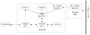
图2示出了一种可能的移动终端的结构示意图。参阅图2可知,该移动终端包括融合单元21、V2X计算单元22、第一TBOX通信单元23、定位单元24、无线通信单元25、采集单元26和显示单元27,其中:FIG. 2 shows a schematic structural diagram of a possible mobile terminal. 2, the mobile terminal includes a fusion unit 21, a V2X calculation unit 22, a first TBOX communication unit 23, a positioning unit 24, a wireless communication unit 25, a collection unit 26 and a display unit 27, wherein:
融合单元21,能够获取T-BOX/OBD、定位单元24、采集单元26、TCU服务器采集的包含车辆的状态数据的V2X报文字段、并将获取到的V2X报文字段进行综合得到第一V2X报文,并利用采集单元26采集的车辆周围的障碍物的状态数据进行障碍物融合得到第一障碍物位图。The fusion unit 21 can acquire the V2X message fields including the vehicle status data collected by the T-BOX/OBD, the positioning unit 24, the acquisition unit 26, and the TCU server, and synthesize the acquired V2X message fields to obtain the first V2X message, and use the state data of obstacles around the vehicle collected by the collecting unit 26 to perform obstacle fusion to obtain a first obstacle bitmap.
V2X计算单元22:能够通过无线通信单元25,接收TCU服务器发送的第二障碍物位图,利用第二障碍物位图完成V2X业务计算;可选的,也可以将第二障碍物位图发送给融合单元21。V2X computing unit 22: can receive the second obstacle bitmap sent by the TCU server through the wireless communication unit 25, and use the second obstacle bitmap to complete the V2X service calculation; optionally, the second obstacle bitmap can also be sent to the fusion unit 21.
本申请中在移动终端和车载T-BOX/OBD之间新增T-BOX通信单元,实现移动终端和车载TBOX/OBD之间的通信,其中,第一TBOX通信单元23位于移动终端上,第二TBOX通信单元位于车载TBOX/OBD上,用于定时向移动终端上报车辆的状态数据。In this application, a new T-BOX communication unit is added between the mobile terminal and the vehicle-mounted T-BOX/OBD to realize the communication between the mobile terminal and the vehicle-mounted T-BOX/OBD, wherein the first TBOX communication unit 23 is located on the mobile terminal, The two TBOX communication unit is located on the vehicle TBOX/OBD, and is used to regularly report the status data of the vehicle to the mobile terminal.
定位单元24:用于实现移动终端或车辆的高精度定位,为了实现车辆的高精度定位功能,可选的,定位单元24可以位于移动终端上或位于车载T-BOX/OBD上,可选的,TCU服务器可为定位单元24提供网络改正数服务。The positioning unit 24 is used to realize the high-precision positioning of the mobile terminal or the vehicle. In order to realize the high-precision positioning function of the vehicle, optionally, the positioning unit 24 can be located on the mobile terminal or on the vehicle T-BOX/OBD. , the TCU server can provide network correction service for the positioning unit 24 .
采集单元26:能够采集移动终端内置的传感器或其他车载传感器感知到的车辆的状态数据和车辆周围的障碍物的状态数据。Collection unit 26 : capable of collecting the state data of the vehicle and the state data of obstacles around the vehicle sensed by sensors built in the mobile terminal or other on-board sensors.
无线通信单元:用于实现移动终端与TCU服务器之间的无线通信功能。Wireless communication unit: used to realize the wireless communication function between the mobile terminal and the TCU server.
显示单元27:移动终端具备的具有显示功能和声音功能的单元。Display unit 27: a unit with a display function and a sound function provided in the mobile terminal.
基于图2所示的终端结构示意图,图3所示为本申请实施例中的一种V2X通信方法流程图,具体流程包括以下步骤:Based on the schematic diagram of the terminal structure shown in FIG. 2 , FIG. 3 shows a flowchart of a V2X communication method in an embodiment of the present application, and the specific process includes the following steps:
步骤30:TCU服务器向定位单元24下发RTK改正数。Step 30: The TCU server sends the RTK correction number to the positioning unit 24.
TCU服务器在下发RTK改正数时周期性下发。The TCU server periodically delivers the RTK correction number when delivering the RTK correction number.
步骤31:融合单元21获取移动终端所处的车辆的状态数据和所述车辆周围的障碍物的状态数据。Step 31: The fusion unit 21 acquires the state data of the vehicle where the mobile terminal is located and the state data of the obstacles around the vehicle.
其中,融合单元21获取车辆的状态数据时,从所述车辆的车载TBOX/OBD、所述TCU服务器、所述终端的采集单元、所述终端的定位单元中至少一项来获取;同时,融合单元21在获取所述车辆周围的障碍物的状态数据时从所述车辆的车载TBOX/OBD、所述TCU服务器、所述终端的采集单元、所述终端的定位单元中至少一项来获取。Wherein, when the fusion unit 21 acquires the state data of the vehicle, it is acquired from at least one of the vehicle's on-board TBOX/OBD, the TCU server, the acquisition unit of the terminal, and the positioning unit of the terminal; The unit 21 acquires the status data of obstacles around the vehicle from at least one of the on-board TBOX/OBD of the vehicle, the TCU server, the collection unit of the terminal, and the positioning unit of the terminal.
步骤32:融合单元21根据获取到的车辆的状态数据生成第一V2X报文,以及根据获取到的障碍物的状态数据生成第一障碍物位图。Step 32: The fusion unit 21 generates a first V2X message according to the obtained state data of the vehicle, and generates a first obstacle bitmap according to the obtained state data of the obstacle.
需要说明的是,采集单元26、车载TBOX/OBD和TCU服务器上报的V2X报文字段中携带障碍物的状态数据,融合单元21根据获取到的所有障碍物的状态数据进行障碍物融合得到第一障碍物位图。It should be noted that the V2X message fields reported by the acquisition unit 26, the vehicle-mounted TBOX/OBD and the TCU server carry the status data of the obstacles, and the fusion unit 21 performs obstacle fusion according to the obtained status data of all obstacles to obtain the first block. Obstacle bitmap.
具体的,融合单元21在生成第一障碍物位图时,可以通过以下过程实现:Specifically, when the fusion unit 21 generates the first obstacle bitmap, it can be implemented through the following process:
S1:获取所述车辆周围的每个障碍物在对应的发现时刻的状态数据。S1: Acquire state data of each obstacle around the vehicle at the corresponding discovery moment.
S2:根据每个障碍物在对应的发现时刻的状态数据,预测每个障碍物在第一时刻的状态数据,得到所述第一障碍物位图,所述第一时刻晚于所述发现时刻。S2: According to the state data of each obstacle at the corresponding discovery time, predict the state data of each obstacle at the first time to obtain the first obstacle bitmap, and the first time is later than the discovery time .
进一步的,上述步骤S2中,所述融合单元21在根据每个障碍物在对应的发现时刻的状态数据,预测每个障碍物在第一时刻的状态数据,得到所述第一障碍物位图时,可以通过以下过程实现:Further, in the above step S2, the fusion unit 21 predicts the state data of each obstacle at the first moment according to the state data of each obstacle at the corresponding discovery time, and obtains the first obstacle bitmap. , it can be achieved by the following process:
S21:根据每个障碍物在对应的发现时刻的状态数据,预测每个障碍物在第一时刻的状态数据。S21: According to the state data of each obstacle at the corresponding discovery time, predict the state data of each obstacle at the first time.
例如,障碍物的状态数据包括障碍物的位置、头指向、速度,可选的,速度还可以包括瞬时速度、加速度、角速度、角加速度等参数。此时,已知障碍物的发现时刻和第一时刻,利用障碍物的状态数据能够预测障碍物在第一时刻的状态数据。For example, the status data of the obstacle includes the position, head orientation, and velocity of the obstacle. Optionally, the velocity may also include parameters such as instantaneous velocity, acceleration, angular velocity, and angular acceleration. At this time, the discovery time and the first time of the obstacle are known, and the state data of the obstacle at the first time can be predicted by using the state data of the obstacle.
举例来说,若障碍物为行人甲,发现时刻为9:00,行人甲的状态信息包括头指向即运动方向、速度v和位置A,假设运动方向为向东运动,速度v为6KM/h,已知当前时刻为9:01,行人甲在当前时刻的预测位置为发现位置A向东移动6*1/60=0.1KM,速度和运动方向保持不变。For example, if the obstacle is a pedestrian A, the time of discovery is 9:00, the state information of the pedestrian A includes the head pointing, the moving direction, the speed v and the position A, assuming that the moving direction is eastward, the speed v is 6KM/h , it is known that the current time is 9:01, the predicted position of pedestrian A at the current time is that the position A moves eastward by 6*1/60=0.1KM, and the speed and movement direction remain unchanged.
S22:将预测的状态数据相同的障碍物进行合并,得到第一障碍物位图。S22: Combine obstacles with the same predicted state data to obtain a first obstacle bitmap.
例如,若2个障碍物存在预测位置重叠且速度、头指向等状态数据相同或相近的情形,则将这2个障碍物合并为1个障碍物。For example, if the predicted positions of two obstacles overlap and the state data such as speed and head direction are the same or similar, the two obstacles will be merged into one obstacle.
S23:确定合并后的障碍物为有效障碍物后,将障碍物的预测位置叠加到所述车辆的可行驶区域。S23: After the combined obstacle is determined to be an effective obstacle, the predicted position of the obstacle is superimposed on the drivable area of the vehicle.
一种可能的设计中,若连续若干周期均被发现的障碍物为有效障碍物。In a possible design, an obstacle that is found in several consecutive cycles is an effective obstacle.
另一种可能的设计中,将TCU服务器或车载TBOX/OBD同时发现上报的障碍物作为有效障碍物。In another possible design, the obstacles detected and reported by the TCU server or the vehicle TBOX/OBD at the same time are used as effective obstacles.
值得一提的是,将障碍物的预测位置叠加到所述车辆的可行驶区域后,为了避免将路沿误判为障碍物,在步骤S24执行之前,可选的,将所述可行驶区域进行收缩。例如,将可行驶区域收缩0.2米后再消除车辆的可行驶区域之外的障碍物,避免将路沿误判为障碍物。It is worth mentioning that, after the predicted position of the obstacle is superimposed on the drivable area of the vehicle, in order to avoid misjudging the road edge as an obstacle, before step S24 is executed, optionally, the drivable area is to shrink. For example, reduce the drivable area by 0.2 meters and then remove obstacles outside the drivable area of the vehicle to avoid misjudging the road edge as an obstacle.
S24:消除车辆的可行驶区域之外的障碍物,得到所述障碍物在第一时刻的第一障碍物位图。S24: Eliminate obstacles outside the drivable area of the vehicle, and obtain a first obstacle bitmap of the obstacle at the first moment.
步骤33:融合单元21将第一V2X报文和第一障碍物位图通过V2X计算单元上报给TCU服务器。Step 33: The fusion unit 21 reports the first V2X packet and the first obstacle bitmap to the TCU server through the V2X computing unit.
步骤34:TCU服务器根据接收到的第一V2X报文和第一障碍物位图进行障碍物融合得到第二障碍物位图。Step 34: The TCU server performs obstacle fusion according to the received first V2X message and the first obstacle bitmap to obtain a second obstacle bitmap.
步骤35:TCU服务器将第二障碍物位图发送至V2X计算单元22。Step 35: The TCU server sends the second obstacle bitmap to the V2X computing unit 22.
可选的,TCU服务器同时将车辆行驶线发送至V2X计算单元22。Optionally, the TCU server sends the vehicle travel line to the V2X computing unit 22 at the same time.
步骤36:V2X计算单元22根据第二障碍物位图,以及定位单元24获取的所述移动终端所处的车辆的定位信息,生成第一预警信息。Step 36 : The V2X computing unit 22 generates first warning information according to the second obstacle bitmap and the positioning information of the vehicle where the mobile terminal is located and obtained by the positioning unit 24 .
一种可能的实现方式中,V2X计算单元22获取车辆的车辆行驶线,根据所述车辆行驶线和所述第二障碍物位图,以及所述车辆的定位信息,确定所述车辆与所述第二障碍物位图中指示的障碍物可能发生碰撞的危险区域,生成所述车辆的第一预警信息。In a possible implementation manner, the V2X computing unit 22 obtains the vehicle driving line of the vehicle, and determines the relationship between the vehicle and the vehicle according to the vehicle driving line, the second obstacle bitmap, and the positioning information of the vehicle. In the danger area where the obstacle indicated in the second obstacle bitmap may collide, the first warning information of the vehicle is generated.
可选的,V2X计算单元22可以通过TCU服务器获取车辆的车辆行驶线;或者,根据车辆的行驶地图获取车辆的车辆行驶线。Optionally, the V2X computing unit 22 may obtain the vehicle travel line of the vehicle through the TCU server; or obtain the vehicle travel line of the vehicle according to the travel map of the vehicle.
需要说明的是,本实施例中以定位单元24位于移动终端进行说明的,可选的,定位单元24也可以位于车载T-BOX/OBD上,或者位于所述第三方定位设备上,只要能实现车辆的高精度定位功能即可,这里的第三方定位设备指的是除移动终端和车载T-BOX/OBD之外的能够实现车辆定位的设备。It should be noted that, in this embodiment, the positioning unit 24 is located on the mobile terminal for description. Optionally, the positioning unit 24 may also be located on the vehicle-mounted T-BOX/OBD, or on the third-party positioning device, as long as it can It is enough to realize the high-precision positioning function of the vehicle. The third-party positioning device here refers to the device that can realize the vehicle positioning except the mobile terminal and the vehicle-mounted T-BOX/OBD.
步骤37:V2X计算单元22将第一预警信息发送给显示单元27进行显示。Step 37: The V2X computing unit 22 sends the first warning information to the display unit 27 for display.
需要说明的是,第一预警信息可以是图形化的危险区域,可选的,可以展现在车辆的行驶地图中;或者,以语音方式提示危险区域。It should be noted that the first warning information may be a graphical dangerous area, and optionally, may be displayed on a driving map of the vehicle; or, the dangerous area may be prompted in a voice manner.
基于图2所示的终端结构示意图,图4所示为本申请实施例中的另一种V2X通信方法流程图,具体流程包括以下步骤:Based on the schematic diagram of the terminal structure shown in FIG. 2, FIG. 4 shows a flowchart of another V2X communication method in the embodiment of the present application, and the specific process includes the following steps:
步骤41~步骤44可参阅上述步骤31~步骤34,在此不再赘述。For steps 41 to 44, reference may be made to the above-mentioned steps 31 to 34, which will not be repeated here.
步骤45:TCU服务器根据第二障碍物位图,以及定位单元24获取的移动终端所处的车辆的定位信息生成第二预警信息。Step 45 : The TCU server generates second warning information according to the second obstacle bitmap and the positioning information of the vehicle where the mobile terminal is located obtained by the positioning unit 24 .
一种可能的实现方式中,TCU服务器获取车辆的定位信息,根据车辆行驶线和第二障碍物位图,以及所述车辆的定位信息,确定所述车辆与所述第二障碍物位图中指示的障碍物可能发生碰撞的危险区域,生成第二预警信息。In a possible implementation manner, the TCU server obtains the positioning information of the vehicle, and determines the vehicle and the second obstacle bitmap according to the vehicle driving line and the second obstacle bitmap, as well as the positioning information of the vehicle. The indicated obstacle may collide with the dangerous area, and the second warning information is generated.
步骤46:TCU服务器将第二预警信息发送至所述终端的显示单元27进行显示。Step 46: The TCU server sends the second warning information to the display unit 27 of the terminal for display.
基于图2所示的终端结构示意图,图5所示为本申请实施例中的另一种V2X通信方法流程图,具体流程包括以下步骤:Based on the schematic diagram of the terminal structure shown in FIG. 2, FIG. 5 shows a flowchart of another V2X communication method in this embodiment of the present application, and the specific process includes the following steps:
步骤51~步骤55可参阅上述步骤31~步骤35,在此不再赘述。For steps 51 to 55, reference may be made to the above-mentioned steps 31 to 35, which will not be repeated here.
步骤56:V2X计算单元22根据所述第一障碍物位图与所述第二障碍物位图进行障碍物融合得到第三障碍物位图。Step 56: The V2X computing unit 22 performs obstacle fusion according to the first obstacle bitmap and the second obstacle bitmap to obtain a third obstacle bitmap.
V2X计算单元22在得到第三障碍物位图时,一种可能的设计中,V2X计算单元在第二时刻重新获取所述车辆周围的障碍物的状态数据,并根据根据重新获取到的障碍物的状态数据更新第一障碍物位图,所述更新后的第一障碍物位图是第二时刻的障碍物位图,所述第一障碍物位图为第一时刻的障碍物位图,所述第二时刻晚于所述第一时刻;将更新后的第一障碍物位图与所述第二障碍物位图进行障碍物融合得到第三障碍物位图。When the V2X computing unit 22 obtains the third obstacle bitmap, in a possible design, the V2X computing unit re-acquires the state data of the obstacles around the vehicle at the second moment, and according to the re-obtained obstacles Update the first obstacle bitmap according to the state data of , the updated first obstacle bitmap is the obstacle bitmap at the second moment, and the first obstacle bitmap is the obstacle bitmap at the first moment, The second time is later than the first time; the updated first obstacle bitmap and the second obstacle bitmap are subjected to obstacle fusion to obtain a third obstacle bitmap.
V2X计算单元22在得到第三障碍物位图时,另一种可能的设计中,V2X计算单元在第二时刻从融合单元21获取更新后的第一障碍物位图,此时融合单元21对第一障碍物位图进行更新,所述更新后的第一障碍物位图是第二时刻的障碍物位图;将更新后的第一障碍物位图与所述第二障碍物位图进行障碍物融合得到第三障碍物位图。When the V2X computing unit 22 obtains the third obstacle bitmap, in another possible design, the V2X computing unit obtains the updated first obstacle bitmap from the fusion unit 21 at the second moment. The first obstacle bitmap is updated, and the updated first obstacle bitmap is the obstacle bitmap at the second moment; the updated first obstacle bitmap is updated with the second obstacle bitmap. Obstacle fusion obtains the third obstacle bitmap.
一种可能的设计中,V2X计算单元22在得到第三障碍物位图时,可以通过以下过程实现:In a possible design, when the V2X computing unit 22 obtains the third obstacle bitmap, it can be implemented through the following process:
步骤P1:从所述第二障碍物位图中获取所述第二障碍物位图中每个障碍物在第三时刻的状态数据,根据所述第二障碍物位图中每个障碍物在所述第三时刻的状态数据,预测所述第二障碍物位图中每个障碍物在第四时刻的状态数据得到预测后的第二障碍物位图,所述第四时刻晚于所述第三时刻。Step P1: Obtain the state data of each obstacle in the second obstacle bitmap at the third moment from the second obstacle bitmap. According to the second obstacle bitmap, each obstacle is in The state data at the third time is the predicted second obstacle bitmap obtained by predicting the state data of each obstacle in the second obstacle bitmap at the fourth time, and the fourth time is later than the The third moment.
步骤P2:将更新后的第一障碍物位图和预测后的第二障碍物位图进行叠加。Step P2: Superimpose the updated first obstacle bitmap and the predicted second obstacle bitmap.
步骤P3:在叠加得到的障碍物位图指示的障碍物中,将状态数据相同的至少两个障碍物合并为一个障碍物,所述至少两个障碍物为所述更新后的第一障碍物位图和所述预测后的第二障碍物位图中至少一项中的障碍物。Step P3: Among the obstacles indicated by the superimposed obstacle bitmap, combine at least two obstacles with the same state data into one obstacle, and the at least two obstacles are the updated first obstacles An obstacle in at least one item in the bitmap and the predicted second obstacle bitmap.
需要说明的是,所述至少两个障碍物分别来自于更新后的第一障碍物位图和所述预测后的第二障碍物位图中;可选的,所述至少两个障碍物也可以都来自于更新后的第一障碍物位图或者都来自于预测后的第二障碍物位图,若所述至少两个障碍物都来自于同一个障碍物位图,表明该同一个障碍物位图在生成时没有执行相同障碍物的合并操作。It should be noted that the at least two obstacles are respectively from the updated first obstacle bitmap and the predicted second obstacle bitmap; optionally, the at least two obstacles are also Both can come from the updated first obstacle bitmap or both come from the predicted second obstacle bitmap. If the at least two obstacles come from the same obstacle bitmap, it indicates that the same obstacle The bitmap was generated without performing a merge operation of the same obstacles.
步骤P4:根据经过合并处理的每个障碍物的状态数据,得到所述第三障碍物位图。Step P4: Obtain the third obstacle bitmap according to the merged state data of each obstacle.
需要说明的是,第四时刻晚于第三时刻,可选的,第三时刻可以为第二障碍物位图的生成时刻或者为第二障碍物位图发送给移动终端的发送时刻;第四时刻可以为第二时刻或者为移动终端设置的融合第三障碍物位图的融合时刻。It should be noted that the fourth time is later than the third time. Optionally, the third time may be the time when the second obstacle bitmap is generated or the time when the second obstacle bitmap is sent to the mobile terminal; the fourth time The moment may be the second moment or the fusion moment set for the mobile terminal to fuse the third obstacle bitmap.
若所述第四时刻为融合时刻时,V2X计算单元22在得到第三障碍物位图时,可选的,还需要对更新后的第一障碍物位图进行预测,具体的,上述步骤P1中,还需要执行:从更新后的第一障碍物位图中获取所述更新后的第一障碍物位图中每个障碍物在第三时刻的状态数据,根据所述更新后的第一障碍物位图中每个障碍物在所述第三时刻的状态数据,预测所述更新后的第一障碍物位图中每个障碍物在第四时刻的状态数据得到更新的第一障碍物位图。If the fourth moment is the fusion moment, when the V2X computing unit 22 obtains the third obstacle bitmap, optionally, it also needs to predict the updated first obstacle bitmap. Specifically, the above step P1 , it is also necessary to execute: obtain the status data of each obstacle at the third moment in the updated first obstacle bitmap from the updated first obstacle bitmap, and according to the updated first obstacle bitmap The state data of each obstacle in the obstacle bitmap at the third moment, and the first obstacle is predicted to be updated from the status data of each obstacle at the fourth moment in the updated first obstacle bitmap bitmap.
进一步的,在步骤P4执行之前,还需执行:确定经过合并处理每个障碍物为有效障碍物后,将每个障碍物的预测位置叠加到所述车辆的可行驶区域。Further, before step P4 is executed, it is also necessary to execute: after each obstacle is determined to be an effective obstacle after being merged and processed, the predicted position of each obstacle is superimposed on the drivable area of the vehicle.
一种可能的设计中,若连续若干周期均被发现的障碍物为有效障碍物。In a possible design, an obstacle that is found in several consecutive cycles is an effective obstacle.
另一种可能的设计中,将TCU服务器或车载TBOX/OBD同时发现上报的障碍物作为有效障碍物。In another possible design, the obstacles detected and reported by the TCU server or the vehicle TBOX/OBD at the same time are used as effective obstacles.
值得一提的是,将障碍物的预测位置叠加到所述车辆的可行驶区域后,为了避免将路沿误判为障碍物,可选的,将所述可行驶区域进行收缩。例如,将可行驶区域收缩0.2米后再消除车辆的可行驶区域之外的障碍物,避免将路沿误判为障碍物,然后,获取每个障碍物在第四时刻的状态数据得到第三障碍物位图。It is worth mentioning that after the predicted position of the obstacle is superimposed on the drivable area of the vehicle, in order to avoid misjudging the road edge as an obstacle, optionally, the drivable area is shrunk. For example, after shrinking the drivable area by 0.2 meters, the obstacles outside the drivable area of the vehicle are eliminated to avoid misjudging the road edge as an obstacle. Then, the state data of each obstacle at the fourth moment is obtained to obtain the third Obstacle bitmap.
步骤57:V2X计算单元根据所述第三障碍物位图,以及所述定位单元24获取的所述移动终端所处的车辆的定位信息,生成第一预警信息,并发送给所述显示单元27进行显示。Step 57: The V2X computing unit generates first warning information according to the third obstacle bitmap and the positioning information of the vehicle in which the mobile terminal is located obtained by the positioning unit 24, and sends it to the display unit 27 to display.
可选的,V2X计算单元22包括综合单元221和生成单元222,此时,步骤56由综合单元221执行,步骤57由生成单元222执行。Optionally, the V2X computing unit 22 includes a synthesis unit 221 and a generation unit 222 . In this case, step 56 is performed by the synthesis unit 221 , and step 57 is performed by the generation unit 222 .
一种可能的实现方式中,V2X计算单元22获取所述车辆的车辆行驶线,根据所述车辆行驶线和所述第三障碍物位图,以及所述车辆的定位信息,确定所述车辆与所述第三障碍物位图中指示的障碍物可能发生碰撞的危险区域,生成所述车辆的第一预警信息。In a possible implementation manner, the V2X computing unit 22 obtains the vehicle driving line of the vehicle, and determines the relationship between the vehicle and the vehicle according to the vehicle driving line, the third obstacle bitmap, and the positioning information of the vehicle. The first warning information of the vehicle is generated in the danger area where the obstacle indicated in the third obstacle bitmap may collide.
可选的,V2X计算单元可以通过TCU服务器获取所述车辆的车辆行驶线;或者,根据车辆的行驶地图获取所述车辆的车辆行驶线。Optionally, the V2X computing unit may obtain the vehicle travel line of the vehicle through the TCU server; or obtain the vehicle travel line of the vehicle according to the vehicle travel map.
图6所示为本申请实施例中的另一种V2X通信方法流程图,该方法应用在TCU服务器侧,具体流程包括以下步骤:FIG. 6 shows a flowchart of another V2X communication method in the embodiment of the present application. The method is applied on the TCU server side, and the specific process includes the following steps:
步骤60:TCU服务器接收至少一个移动终端上报的第一V2X报文和至少一个第一障碍物位图。Step 60: The TCU server receives the first V2X packet and at least one first obstacle bitmap reported by at least one mobile terminal.
步骤61:TCU服务器根据至少一个第一V2X报文得到至少一个障碍物位图,将所述至少一个障碍物位图和所述至少一个第一障碍物位图进行障碍物融合得到的第二障碍物位图。Step 61: The TCU server obtains at least one obstacle bitmap according to the at least one first V2X message, and obtains a second obstacle obtained by performing obstacle fusion on the at least one obstacle bitmap and the at least one first obstacle bitmap. Level map.
例如,步骤61在具体实施时,TCU服务器根据接收到的每个V2X报文,获取该每个V2X报文表征的车辆及车辆的状态数据,将获取到的每个车辆都作为障碍物,从而得到每个V2X报文对应的障碍物位图。For example, when
可选的,所述TCU还获取第一移动终端所处的车辆的车辆行驶线以及所述车辆的定位信息;根据所述车辆行驶线和所述第二障碍物位图,以及所述车辆的定位信息,确定所述车辆与所述第二障碍物位图中指示的障碍物可能发生碰撞的危险区域,生成所述车辆的第二预警信息;并将所述第二预警信息发送给所述第一移动终端。Optionally, the TCU further acquires the vehicle traveling line of the vehicle where the first mobile terminal is located and the positioning information of the vehicle; according to the vehicle traveling line and the second obstacle bitmap, and the positioning information, determine the danger area where the vehicle may collide with the obstacle indicated in the second obstacle bitmap, and generate second warning information of the vehicle; and send the second warning information to the the first mobile terminal.
可选的,所述TCU服务器周期性更新第二障碍物位图,将更新后的第二障碍物位图发送给所述第一移动终端。Optionally, the TCU server periodically updates the second obstacle bitmap, and sends the updated second obstacle bitmap to the first mobile terminal.
下面通过定位单元的不同应用场景描述上述V2X通信方法。The above V2X communication method is described below through different application scenarios of the positioning unit.
应用场景一Application Scenario One
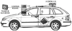
如图7A所示的硬件架构示意图,定位单元位于移动终端上,以移动终端为手机为例进行说明,此时手机提供车辆的高精度定位功能。7A is a schematic diagram of the hardware architecture, the positioning unit is located on the mobile terminal, and the mobile terminal is a mobile phone as an example for illustration. At this time, the mobile phone provides a high-precision positioning function of the vehicle.
由于目前LTE手机的LTE空口和WIFI模块不可同时收发数据,所以本实施中车载T-BOX/OBD和手机的接口虽未限定,但推荐使用蓝牙接口或USB有线接口。Since the LTE air interface and the WIFI module of the LTE mobile phone cannot send and receive data at the same time, the interface between the vehicle T-BOX/OBD and the mobile phone is not limited in this implementation, but it is recommended to use the Bluetooth interface or the USB wired interface.
在本实施例中,手机可以使用内置全球导航卫星系统(Global NavigationSatellite System,GNSS)模块,由于目前的手机GNSS模块的定位精度不能满足V2X需求,所以要求手机支持高精度定位能力,具体包括RTK观测能力、接收改正数的能力和RTK位置解算能力。In this embodiment, the mobile phone can use a built-in Global Navigation Satellite System (GNSS) module. Since the positioning accuracy of the current mobile phone GNSS module cannot meet the V2X requirements, the mobile phone is required to support high-precision positioning capabilities, including RTK observation. capabilities, the ability to receive corrections, and the ability to resolve RTK positions.
此外,在本实施例中,为了实现手机的高精度定位功能,TCU服务器需要为手机提供RTK改正数。In addition, in this embodiment, in order to realize the high-precision positioning function of the mobile phone, the TCU server needs to provide the RTK correction number for the mobile phone.
进一步的,考虑到目前手机的内置天线无法满足RTK需求,可考虑在车辆顶部安装外置RTK天线,外置RTK天线和手机的通讯也可利用蓝牙接口或USB有线接口。Further, considering that the built-in antenna of the mobile phone cannot meet the RTK requirements, an external RTK antenna can be installed on the top of the vehicle. The communication between the external RTK antenna and the mobile phone can also use a Bluetooth interface or a USB wired interface.
针对图7A的硬件架构,图7B示出了该种硬件架构下的模块组成示意图。Regarding the hardware architecture of FIG. 7A , FIG. 7B shows a schematic diagram of the composition of modules under the hardware architecture.
上述应用场景能够在不改变公网通讯模式和现有终端的前提下,实现V2X业务。The above application scenarios can implement V2X services without changing the public network communication mode and existing terminals.
应用场景二Application Scenario 2
如图8A所示的硬件结构示意图,定位单元位于车载T-BOX/OBD,以移动终端为手机为例进行说明,此时车载T-BOX/OBD提供车辆的高精度定位功能。8A shows the schematic diagram of the hardware structure, the positioning unit is located in the vehicle T-BOX/OBD, taking the mobile terminal as a mobile phone as an example to illustrate, at this time, the vehicle T-BOX/OBD provides the high-precision positioning function of the vehicle.
需要说明的是,与应用场景一相同,车载T-BOX/OBD和手机的接口推荐使用蓝牙接口或USB有线接口。It should be noted that, the same as the
注意,如果车载T-BOX/OBD支持高精度定位功能,则本实施中可以降低对手机的性能要求。Note that if the vehicle-mounted T-BOX/OBD supports the high-precision positioning function, the performance requirements for the mobile phone can be reduced in this implementation.
在本实施例中,为了实现车载TCUT-BOX/OBD的高精度定位功能,TCU服务器需要为车载T-BOX/OBD提供RTK改正数,In this embodiment, in order to realize the high-precision positioning function of the vehicle-mounted TCUT-BOX/OBD, the TCU server needs to provide the RTK correction number for the vehicle-mounted T-BOX/OBD.
同理,如果车载T-BOX/OBD的内置天线无法满足RTK需求,可考虑在车辆的顶部安装外置RTK天线,外置RTK天线和车载T-BOX/OBD通讯也可利用蓝牙接口或USB有线接口。Similarly, if the built-in antenna of the on-board T-BOX/OBD cannot meet the RTK requirements, consider installing an external RTK antenna on the top of the vehicle. The external RTK antenna and on-board T-BOX/OBD communication can also use the Bluetooth interface or USB cable. interface.
针对图8A的硬件架构,图8B示出了该种硬件架构下的模块组成示意图。此时,车载T-BOX/OBD需内置具备高精度定位功能的的定位单元;车载T-BOX/OBD需支持接收RTK改正数,所述RTK改正数由TCU服务器生成并发送或转发基站生成的RTK改正数。。Regarding the hardware architecture of FIG. 8A , FIG. 8B shows a schematic diagram of the composition of modules under the hardware architecture. At this time, the vehicle-mounted T-BOX/OBD needs to have a built-in positioning unit with high-precision positioning function; the vehicle-mounted T-BOX/OBD needs to support receiving RTK correction numbers, which are generated by the TCU server and sent or forwarded by the base station. RTK correction number. .
此外,车载T-BOX/OBD应具备RTK观测值采集功能,如果车载T-BOX/OBD的内置天线无法采集RTK改正数或无法满足V2X业务对定位鲁棒性的要求,应可支持外置RTK级别的GNSS天线。In addition, the vehicle-mounted T-BOX/OBD should have the function of collecting RTK observations. If the built-in antenna of the vehicle-mounted T-BOX/OBD cannot collect RTK corrections or cannot meet the requirements of V2X service for positioning robustness, it should be able to support external RTK Class GNSS antenna.
本实施例中,车载T-BOX/OBD自身具备高精度定位能力,则手机不用支持高精度定位,从而适用更多的手机型号,在不改变公网通讯模式和手机现有装置的前提下,实现V2X业务。In this embodiment, the vehicle-mounted T-BOX/OBD itself has high-precision positioning capability, so the mobile phone does not need to support high-precision positioning, so it is suitable for more mobile phone models. Realize V2X business.
应用场景三Application Scenario Three
在本实施例中,外置第三方定位设备实现车辆的高精度定位功能。In this embodiment, an external third-party positioning device implements the high-precision positioning function of the vehicle.
如果手机、车载T-BOX/OBD均不具备高精度定位能力,则需要外接第三方定位设备,常用如:千寻定位装置,或其他的测绘级定位装置。If the mobile phone and car T-BOX/OBD do not have high-precision positioning capabilities, an external third-party positioning device is required, such as Qianxun positioning device, or other mapping-level positioning devices.
这些第三方定位设备可通过本系统中的TCU服务器及无线通信单元获得RTK改正数,也可通过自身的途径获得RTK改正数,通常商用高精度定位装置具备独立的改正数获得能力,如千寻终端对接千寻网络、商用终端对接CORS系统来获得改正数。These third-party positioning devices can obtain RTK correction numbers through the TCU server and wireless communication unit in this system, or obtain RTK correction numbers through their own channels. Usually commercial high-precision positioning devices have the ability to obtain independent correction numbers, such as Chihiro. The terminal is connected to the Qianxun network, and the commercial terminal is connected to the CORS system to obtain the correction number.
如果车辆内部存在第三方定位设备,则手机、车载T-BOX/OBD不用支持高精度定位,从而适用更多的手机、车载T-BOX/OBD型号,在不改变公网通讯模式和手机现有装置的前提下,实现V2X业务。If there is a third-party positioning device inside the vehicle, the mobile phone and vehicle-mounted T-BOX/OBD do not need to support high-precision positioning, so more mobile phone and vehicle-mounted T-BOX/OBD models are applicable, without changing the public network communication mode and the existing mobile phone On the premise of the device, the V2X service can be realized.
基于相同的发明构思,如图9所示,为本申请实施例提供的一种装置示意图,该装置可以是移动终端、TCU服务器或芯片,可执行上述任一实施例的方法。Based on the same inventive concept, as shown in FIG. 9 , a schematic diagram of a device provided in an embodiment of the present application is provided. The device may be a mobile terminal, a TCU server, or a chip, and may execute the method of any of the foregoing embodiments.
该装置900包括至少一个处理器901,通信线路902,存储器903以及至少一个通信接口904。The
处理器901可以是一个通用中央处理器(central processing unit,CPU),微处理器,特定应用集成电路(application-specific integrated circuit,服务器IC),或一个或多个用于控制本申请方案程序执行的集成电路。The
通信线路902可包括一通路,在上述组件之间传送信息。Communication line 902 may include a path to communicate information between the components described above.
通信接口904,使用任何收发器一类的装置,用于与其他设备或通信网络通信,如以太网,无线接入网(radio access network,RAN),无线局域网(wireless local areanetworks,WLAN)等。The
存储器903可以是只读存储器(read-only memory,ROM)或可存储静态信息和指令的其他类型的静态存储设备,随机存取存储器(random access memory,RAM)或者可存储信息和指令的其他类型的动态存储设备,也可以是电可擦可编程只读存储器(electricallyer服务器able programmable read-only memory,EEPROM)、只读光盘(compact discread-only memory,CD-ROM)或其他光盘存储、光碟存储(包括压缩光碟、激光碟、光碟、数字通用光碟、蓝光光碟等)、磁盘存储介质或者其他磁存储设备、或者能够用于携带或存储具有指令或数据结构形式的期望的程序代码并能够由计算机存取的任何其他介质,但不限于此。存储器可以是独立存在,通过通信线路902与处理器相连接。存储器也可以和处理器集成在一起。
其中,存储器903用于存储执行本申请方案的计算机执行指令,并由处理器901来控制执行。处理器901用于执行存储器903中存储的计算机执行指令,从而实现本申请上述实施例提供的V2X的通信方法。The
可选的,本申请实施例中的计算机执行指令也可以称之为应用程序代码,本申请实施例对此不作具体限定。Optionally, the computer-executed instructions in the embodiment of the present application may also be referred to as application code, which is not specifically limited in the embodiment of the present application.
在具体实现中,作为一种实施例,处理器901可以包括一个或多个CPU,例如图9中的CPU0和CPU1。In a specific implementation, as an embodiment, the
在具体实现中,作为一种实施例,装置900可以包括多个处理器,例如图9中的处理器901和处理器908。这些处理器中的每一个可以是一个单核(single-CPU)处理器,也可以是一个多核(multi-CPU)处理器。这里的处理器可以指一个或多个设备、电路、和/或用于处理数据(例如计算机程序指令)的处理核。In a specific implementation, as an embodiment, the
在具体实现中,作为一种实施例,装置900还可以包括输出设备905和输入设备906。输出设备905和处理器901通信,可以以多种方式来显示信息。例如,输出设备905可以是液晶显示器(liquid crystal display,LCD),发光二级管(light emitting diode,LED)显示设备,阴极射线管(cathode ray tube,CRT)显示设备,或投影仪(projector)等。输入设备906和处理器901通信,可以以多种方式接收用户的输入。例如,输入设备906可以是鼠标、键盘、触摸屏设备或传感设备等。In a specific implementation, as an embodiment, the
上述的装置900可以是一个通用设备或者是一个专用设备。在具体实现中,装置900可以是台式机、便携式电脑、网络服务器、掌上电脑(personal digital服务器sistant,PDA)、移动手机、平板电脑、无线终端设备、嵌入式设备或有图9中类似结构的设备。本申请实施例不限定装置900的类型。The above-mentioned
当图9所示的装置为芯片时,例如可以是移动终端的芯片或TCU服务器的芯片,则该芯片包括处理器901(还可以包括处理器908)、通信线路902、存储器903和通信接口904。具体地,通信接口904可以是输入接口、管脚或电路等。存储器903可以是寄存器、缓存等。处理器901和处理器908可以是一个通用的CPU,微处理器,ASIC,或一个或多个用于控制上述任一实施例的V2X的通信方法的程序执行的集成电路。When the device shown in FIG. 9 is a chip, such as a chip of a mobile terminal or a chip of a TCU server, the chip includes a processor 901 (and also a processor 908 ), a communication line 902 , a
本申请可以根据上述方法示例对装置进行功能模块的划分,例如,可以对应各个功能划分各个功能模块,也可以将两个或两个以上的功能集成在一个处理模块中。上述集成的模块既可以采用硬件的形式实现,也可以采用软件功能模块的形式实现。需要说明的是,本申请中对模块的划分是示意性的,仅仅为一种逻辑功能划分,实际实现时可以有另外的划分方式。比如,在采用对应各个功能划分各个功能模块的情况下,图10示出了一种装置示意图,该装置1000可以是上述实施例中所涉及的移动终端,该装置1000包括显示单元1001、融合单元1002和V2X计算单元1003。可选地,V2X计算单元1003包括综合单元31和生成单元32。The present application may divide the device into functional modules according to the above method examples. For example, each functional module may be divided corresponding to each function, or two or more functions may be integrated into one processing module. The above-mentioned integrated modules can be implemented in the form of hardware, and can also be implemented in the form of software function modules. It should be noted that the division of modules in this application is schematic, and is only a logical function division, and other division methods may be used in actual implementation. For example, in the case where each functional module is divided according to each function, FIG. 10 shows a schematic diagram of an apparatus, the
所述融合单元1002,用于获取所述移动终端所处的车辆的状态数据和所述车辆周围的障碍物的状态数据,并根据获取到的车辆的状态数据生成第一V2X报文,以及根据获取到的障碍物的状态数据生成第一障碍物位图,将生成的所述第一V2X报文和所述第一障碍物位图发送给TCU服务器;The
所述V2X计算单元1003,用于接收所述TCU服务器发送的第二障碍物位图;根据所述第二障碍物位图,以及所述车辆的定位信息,生成用于所述显示单元1001显示的第一预警信息;其中,所述第二障碍物位图为所述TCU服务器根据所述第一V2X报文得到的障碍物位图和所述第一障碍物位图进行融合得到的障碍物位图。The
可选的,所述移动终端所处的车辆的定位信息来自定位单元,所述定位单元位于所述装置1000;或者所述定位单元位于车载T-BOX/OBD。Optionally, the positioning information of the vehicle where the mobile terminal is located comes from a positioning unit, and the positioning unit is located in the
可选的,所述V2X计算单元1003还用于:Optionally, the
接收所述TCU服务器发送的用于所述显示单元1001显示的第二预警信息,所述第二预警信息为所述TCU服务器根据所述第二障碍物位图,以及所述移动终端所处的车辆的定位信息生成的。Receive the second early warning information sent by the TCU server and used for the
可选的,所述融合单元1002用于:Optionally, the
获取所述车辆周围的每个障碍物在对应的发现时刻的状态数据;Obtain the state data of each obstacle around the vehicle at the corresponding discovery moment;
根据每个障碍物在对应的发现时刻的状态数据,预测每个障碍物在第一时刻的状态数据,得到所述第一障碍物位图,所述第一时刻晚于所述发现时刻。According to the state data of each obstacle at the corresponding discovery time, the state data of each obstacle at the first time is predicted, and the first obstacle bitmap is obtained, and the first time is later than the discovery time.
可选的,所述V2X计算单元1003包括综合单元31和生成单元32:Optionally, the
所述综合单元31,用于在第二时刻重新获取所述车辆周围的障碍物的状态数据,并根据根据重新获取到的障碍物的状态数据更新第一障碍物位图,所述更新后的第一障碍物位图是第二时刻的障碍物位图;将更新后的第一障碍物位图与所述第二障碍物位图进行障碍物融合得到第三障碍物位图;The integration unit 31 is configured to re-acquire the state data of the obstacles around the vehicle at the second moment, and update the first obstacle bitmap according to the re-obtained state data of the obstacles, and the updated The first obstacle bitmap is the obstacle bitmap at the second moment; the updated first obstacle bitmap and the second obstacle bitmap are subjected to obstacle fusion to obtain a third obstacle bitmap;
所述生成单元32,用于根据所述第三障碍物位图,以及所述移动终端所处的车辆的定位信息,生成所述第一预警信息。The generating unit 32 is configured to generate the first warning information according to the third obstacle bitmap and the positioning information of the vehicle where the mobile terminal is located.
可选的,所述综合单元31用于:Optionally, the synthesis unit 31 is used for:
从所述第二障碍物位图中获取所述第二障碍物位图中每个障碍物在第三时刻的状态数据,根据所述第二障碍物位图中每个障碍物在所述第三时刻的状态数据,预测所述第二障碍物位图中每个障碍物在第四时刻的状态数据得到预测后的第二障碍物位图;The state data of each obstacle in the second obstacle bitmap at the third moment is obtained from the second obstacle bitmap. According to the second obstacle bitmap, the status data of each obstacle in the second obstacle bitmap state data at three moments, predicting the state data of each obstacle in the second obstacle bitmap at the fourth moment to obtain a predicted second obstacle bitmap;
将更新后的第一障碍物位图和预测后的第二障碍物位图进行叠加;Superimpose the updated first obstacle bitmap and the predicted second obstacle bitmap;
在叠加得到的障碍物位图中,将状态数据相同的至少两个障碍物合并为一个障碍物,所述至少两个障碍物为所述更新后的第一障碍物位图和所述预测后的第二障碍物位图中至少一项中的障碍物;In the obstacle bitmap obtained by superposition, at least two obstacles with the same state data are combined into one obstacle, and the at least two obstacles are the updated first obstacle bitmap and the predicted an obstacle in at least one item in the second obstacle bitmap of ;
获取经过合并处理的每个障碍物在所述第四时刻的状态数据,得到所述第三障碍物位图。Acquire the state data of each obstacle at the fourth moment that has been merged to obtain the third obstacle bitmap.
可选的,V2X计算单元1003用于:Optionally, the
获取所述车辆的车辆行驶线,根据所述车辆行驶线和所述第二障碍物位图,以及所述车辆的定位信息,确定所述车辆与所述第二障碍物位图中指示的障碍物可能发生碰撞的危险区域,生成所述车辆的第一预警信息。Acquire the vehicle driving line of the vehicle, and determine the obstacles indicated in the vehicle and the second obstacle bitmap according to the vehicle driving line, the second obstacle bitmap, and the positioning information of the vehicle A dangerous area where objects may collide is generated, and first warning information of the vehicle is generated.
可选的,V2X计算单元1003用于:Optionally, the
获取所述车辆的车辆行驶线,根据所述车辆行驶线和所述第三障碍物位图,以及所述车辆的定位信息,确定所述车辆与所述第三障碍物位图中指示的障碍物可能发生碰撞的危险区域,生成所述车辆的第一预警信息。Acquire the vehicle driving line of the vehicle, and determine the vehicle and the obstacle indicated in the third obstacle bitmap according to the vehicle driving line, the third obstacle bitmap, and the positioning information of the vehicle A dangerous area where objects may collide is generated, and first warning information of the vehicle is generated.
可选的,所述车辆的状态数据来自于:Optionally, the state data of the vehicle comes from:
所述车辆的车载TBOX/OBD、所述TCU服务器、所述终端的采集单元、所述终端的定位单元中至少一项;At least one of the on-board TBOX/OBD of the vehicle, the TCU server, the acquisition unit of the terminal, and the positioning unit of the terminal;
所述车辆周围的障碍物的状态数据来自于:The status data of obstacles around the vehicle comes from:
所述车辆的车载TBOX/OBD、所述TCU服务器、所述终端的采集单元、所述终端的定位单元中至少一项。At least one of the on-board TBOX/OBD of the vehicle, the TCU server, the collection unit of the terminal, and the positioning unit of the terminal.
应理解,该装置可以用于实现本发明实施例的方法中由移动终端或手机执行的步骤,相关特征可以参照上文,此处不再赘述。It should be understood that the apparatus can be used to implement the steps performed by the mobile terminal or the mobile phone in the method of the embodiment of the present invention, and the relevant features can be referred to the above, which will not be repeated here.
具体的,图10中的融合单元1002和V2X计算单元1003的功能/实现过程可以通过图9中的处理器901调用存储器903中存储的计算机执行指令来实现,图10中的显示单元1001的功能/实现过程可以通过图9中的输出设备905来实现。Specifically, the functions/implementation process of the
可选的,当该装置1000是芯片时,存储器903可以为芯片内的存储单元,如寄存器、缓存等。当然,当该装置1000是移动终端时,存储器903可以是移动终端内的位于芯片外部的存储单元,本申请实施例对此不作具体限定。Optionally, when the
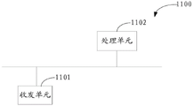
本申请可以根据上述方法示例对装置进行功能模块的划分,例如,可以对应各个功能划分各个功能模块,也可以将两个或两个以上的功能集成在一个处理模块中。上述集成的模块既可以采用硬件的形式实现,也可以采用软件功能模块的形式实现。需要说明的是,本申请中对模块的划分是示意性的,仅仅为一种逻辑功能划分,实际实现时可以有另外的划分方式。比如,在采用对应各个功能划分各个功能模块的情况下,图11示出了一种装置示意图,该装置1100可以是上述实施例中所涉及的TCU服务器,该TCU服务器1100包括收发单元1101和处理单元1102。The present application may divide the device into functional modules according to the above method examples. For example, each functional module may be divided corresponding to each function, or two or more functions may be integrated into one processing module. The above-mentioned integrated modules can be implemented in the form of hardware, and can also be implemented in the form of software function modules. It should be noted that the division of modules in this application is schematic, and is only a logical function division, and other division methods may be used in actual implementation. For example, in the case where each functional module is divided according to each function, FIG. 11 shows a schematic diagram of an apparatus, and the
所述收发单元1101,用于接收至少一个移动终端上报的第一V2X报文和至少一个第一障碍物位图;The
所述处理单元1102,用于根据至少一个第一V2X报文得到至少一个障碍物位图,将所述至少一个障碍物位图和所述至少一个第一障碍物位图进行障碍物融合得到的第二障碍物位图。The
可选的,所述收发单元1101还用于:获取第一移动终端所处的车辆的车辆行驶线以及所述车辆的定位信息;Optionally, the
所述处理单元1102,还用于根据所述车辆行驶线和所述第二障碍物位图,以及所述车辆的定位信息,确定所述车辆与所述第二障碍物位图中指示的障碍物可能发生碰撞的危险区域,生成所述车辆的第二预警信息;The
所述收发单元1101,还用于将所述第二预警信息发送给所述第一移动终端。The
应理解,该装置可以用于实现本发明实施例的方法中由TCU服务器执行的步骤,相关特征可以参照上文,此处不再赘述。It should be understood that the apparatus can be used to implement the steps performed by the TCU server in the method of the embodiment of the present invention, and the relevant features can be referred to above, and details are not repeated here.
具体的,图11中的收发单元1101和处理单元1102的功能/实现过程可以通过图9中的处理器901调用存储器903中存储的计算机执行指令来实现。或者,图11中的处理单元1102的功能/实现过程可以通过图9中的处理器901调用存储器903中存储的计算机执行指令来实现,图11中的收发单元1101的功能/实现过程可以通过图9中的通信接口904来实现。Specifically, the function/implementation process of the
可选的,当该装置1100是芯片时,则收发单元1101的功能/实现过程还可以通过管脚或电路等来实现。可选地,当该装置1100是芯片时,存储器903可以为芯片内的存储单元,如寄存器、缓存等。当然,当该装置1100是TCU服务器时,存储器903可以是TCU服务器内的位于芯片外部的存储单元,本申请实施例对此不作具体限定。Optionally, when the
在上述实施例中,可以全部或部分地通过软件、硬件、固件或者其任意组合来实现。当使用软件实现时,可以全部或部分地以计算机程序产品的形式实现。所述计算机程序产品包括一个或多个计算机指令。在计算机上加载和执行所述计算机程序指令时,全部或部分地产生按照本发明实施例所述的流程或功能。所述计算机可以是通用计算机、专用计算机、计算机网络、或者其他可编程装置。所述计算机指令可以存储在计算机可读存储介质中,或者从一个计算机可读存储介质向另一个计算机可读存储介质传输,例如,所述计算机指令可以从一个网站站点、计算机、服务器或数据中心通过有线(例如同轴电缆、光纤、数字用户线(DSL))或无线(例如红外、无线、微波等)方式向另一个网站站点、计算机、服务器或数据中心进行传输。所述计算机可读存储介质可以是计算机能够存取的任何可用介质或者是包含一个或多个可用介质集成的服务器、数据中心等数据存储设备。所述可用介质可以是磁性介质,(例如,软盘、硬盘、磁带)、光介质(例如,DVD)、或者半导体介质(例如固态硬盘(Solid State Disk,SSD))等。In the above-mentioned embodiments, it may be implemented in whole or in part by software, hardware, firmware or any combination thereof. When implemented in software, it can be implemented in whole or in part in the form of a computer program product. The computer program product includes one or more computer instructions. When the computer program instructions are loaded and executed on a computer, all or part of the processes or functions described in the embodiments of the present invention are generated. The computer may be a general purpose computer, special purpose computer, computer network, or other programmable device. The computer instructions may be stored in or transmitted from one computer readable storage medium to another computer readable storage medium, for example, the computer instructions may be downloaded from a website site, computer, server or data center Transmission to another website site, computer, server, or data center is by wire (eg, coaxial cable, fiber optic, digital subscriber line (DSL)) or wireless (eg, infrared, wireless, microwave, etc.). The computer-readable storage medium may be any available medium that can be accessed by a computer or a data storage device such as a server, data center, etc. that includes an integration of one or more available media. The usable media may be magnetic media (eg, floppy disks, hard disks, magnetic tapes), optical media (eg, DVD), or semiconductor media (eg, Solid State Disk (SSD)), and the like.
本申请实施例中所描述的各种说明性的逻辑单元和电路可以通过通用处理器,数字信号处理器,专用集成电路(ASIC),现场可编程门阵列(FPGA)或其它可编程逻辑装置,离散门或晶体管逻辑,离散硬件部件,或上述任何组合的设计来实现或操作所描述的功能。通用处理器可以为微处理器,可选地,该通用处理器也可以为任何传统的处理器、控制器、微控制器或状态机。处理器也可以通过计算装置的组合来实现,例如数字信号处理器和微处理器,多个微处理器,一个或多个微处理器联合一个数字信号处理器核,或任何其它类似的配置来实现。The various illustrative logic units and circuits described in the embodiments of this application may be implemented by general purpose processors, digital signal processors, application specific integrated circuits (ASICs), field programmable gate arrays (FPGAs) or other programmable logic devices, Discrete gate or transistor logic, discrete hardware components, or any combination of the above are designed to implement or operate the described functions. A general-purpose processor may be a microprocessor, or alternatively, the general-purpose processor may be any conventional processor, controller, microcontroller, or state machine. A processor may also be implemented by a combination of computing devices, such as a digital signal processor and a microprocessor, multiple microprocessors, one or more microprocessors in combination with a digital signal processor core, or any other similar configuration. accomplish.
本申请实施例中所描述的方法或算法的步骤可以直接嵌入硬件、处理器执行的软件单元、或者这两者的结合。软件单元可以存储于RAM存储器、闪存、ROM存储器、EPROM存储器、EEPROM存储器、寄存器、硬盘、可移动磁盘、CD-ROM或本领域中其它任意形式的存储媒介中。示例性地,存储媒介可以与处理器连接,以使得处理器可以从存储媒介中读取信息,并可以向存储媒介存写信息。可选地,存储媒介还可以集成到处理器中。处理器和存储媒介可以设置于ASIC中,ASIC可以设置于终端设备中。可选地,处理器和存储媒介也可以设置于终端设备中的不同的部件中。The steps of the method or algorithm described in the embodiments of this application may be directly embedded in hardware, a software unit executed by a processor, or a combination of the two. A software unit may be stored in RAM memory, flash memory, ROM memory, EPROM memory, EEPROM memory, registers, hard disk, removable disk, CD-ROM, or any other form of storage medium known in the art. Illustratively, a storage medium may be coupled to the processor such that the processor may read information from, and store information in, the storage medium. Optionally, the storage medium can also be integrated into the processor. The processor and storage medium may be provided in the ASIC, and the ASIC may be provided in the terminal device. Alternatively, the processor and the storage medium may also be provided in different components in the terminal device.
这些计算机程序指令也可装载到计算机或其他可编程数据处理设备上,使得在计算机或其他可编程设备上执行一系列操作步骤以产生计算机实现的处理,从而在计算机或其他可编程设备上执行的指令提供用于实现在流程图一个流程或多个流程和/或方框图一个方框或多个方框中指定的功能的步骤。These computer program instructions can also be loaded on a computer or other programmable data processing device to cause a series of operational steps to be performed on the computer or other programmable device to produce a computer-implemented process such that The instructions provide steps for implementing the functions specified in the flow or blocks of the flowcharts and/or the block or blocks of the block diagrams.
尽管结合具体特征及其实施例对本发明进行了描述,显而易见的,在不脱离本发明的精神和范围的情况下,可对其进行各种修改和组合。相应地,本说明书和附图仅仅是所附权利要求所界定的本发明的示例性说明,且视为已覆盖本发明范围内的任意和所有修改、变化、组合或等同物。显然,本领域的技术人员可以对本发明进行各种改动和变型而不脱离本发明的精神和范围。这样,倘若本发明的这些修改和变型属于本发明权利要求及其等同技术的范围之内,则本发明也意图包含这些改动和变型在内。Although the invention has been described in conjunction with specific features and embodiments thereof, it will be apparent that various modifications and combinations can be made therein without departing from the spirit and scope of the invention. Accordingly, this specification and drawings are merely illustrative of the invention as defined by the appended claims, and are deemed to cover any and all modifications, variations, combinations or equivalents within the scope of the invention. It will be apparent to those skilled in the art that various modifications and variations can be made in the present invention without departing from the spirit and scope of the invention. Thus, provided that these modifications and variations of the present invention fall within the scope of the claims of the present invention and their equivalents, the present invention is also intended to include these modifications and variations.
Claims (18)
Priority Applications (1)
| Application Number | Priority Date | Filing Date | Title |
|---|---|---|---|
| CN201711340184.6A CN108200552B (en) | 2017-12-14 | 2017-12-14 | A V2X communication method and device |
Applications Claiming Priority (1)
| Application Number | Priority Date | Filing Date | Title |
|---|---|---|---|
| CN201711340184.6A CN108200552B (en) | 2017-12-14 | 2017-12-14 | A V2X communication method and device |
Publications (2)
| Publication Number | Publication Date |
|---|---|
| CN108200552A CN108200552A (en) | 2018-06-22 |
| CN108200552B true CN108200552B (en) | 2020-08-25 |
Family
ID=62574224
Family Applications (1)
| Application Number | Title | Priority Date | Filing Date |
|---|---|---|---|
| CN201711340184.6A Active CN108200552B (en) | 2017-12-14 | 2017-12-14 | A V2X communication method and device |
Country Status (1)
| Country | Link |
|---|---|
| CN (1) | CN108200552B (en) |
Families Citing this family (15)
| Publication number | Priority date | Publication date | Assignee | Title |
|---|---|---|---|---|
| US11117572B2 (en) * | 2018-08-29 | 2021-09-14 | International Business Machines Corporation | Cognition enabled driving pattern detection |
| CN111292524B (en) * | 2018-12-07 | 2022-03-29 | 中国移动通信集团陕西有限公司 | Congestion information determination method and device, electronic equipment and storage medium |
| CN109677266B (en) * | 2019-01-31 | 2022-03-29 | 大陆汽车车身电子系统(芜湖)有限公司 | Wading state display method for vehicle |
| EP3926435B1 (en) | 2019-02-13 | 2024-06-12 | Beijing Baidu Netcom Science And Technology Co., Ltd. | Driving control method and apparatus, device, medium, and system |
| CN111901777B (en) | 2019-05-06 | 2022-04-05 | 华为技术有限公司 | Communication method, communication device and system |
| CN110782693B (en) * | 2019-08-12 | 2022-07-19 | 腾讯科技(深圳)有限公司 | Positioning method, device and equipment |
| CN110597269B (en) * | 2019-09-30 | 2023-06-02 | 潍柴动力股份有限公司 | Autonomous obstacle avoidance method and autonomous obstacle avoidance system for vehicle |
| CN111030719B (en) * | 2019-11-22 | 2021-10-22 | 华为技术有限公司 | In-vehicle device and data processing method |
| CN111028544A (en) * | 2019-12-06 | 2020-04-17 | 无锡物联网创新中心有限公司 | Pedestrian early warning system with V2V technology and vehicle-mounted multi-sensor integration |
| CN111356083A (en) * | 2020-04-03 | 2020-06-30 | 许昌泛网信通科技有限公司 | Map data filtering and transmitting method for automatic driving vehicle |
| CN111586557B (en) * | 2020-04-03 | 2024-05-03 | 腾讯科技(深圳)有限公司 | Vehicle communication method, device, computer readable medium and electronic device |
| CN111640330A (en) * | 2020-05-29 | 2020-09-08 | 深圳市元征科技股份有限公司 | Anti-collision method based on edge calculation and related device |
| CN115002714B (en) * | 2021-03-02 | 2026-04-24 | 华为技术有限公司 | V2X Communication Methods and Devices |
| CN113205680B (en) * | 2021-04-21 | 2024-08-16 | 腾讯科技(深圳)有限公司 | Collision early warning method and device, electronic equipment and computer readable storage medium |
| CN114926816B (en) * | 2022-05-18 | 2025-02-28 | 中国第一汽车股份有限公司 | A method and system for displaying data fusion results, a vehicle |
Citations (6)
| Publication number | Priority date | Publication date | Assignee | Title |
|---|---|---|---|---|
| CN104678832A (en) * | 2013-11-28 | 2015-06-03 | 现代摩比斯株式会社 | Device For Driving Assist And Method For Activating The Function Automatically By The Device |
| CN106373430A (en) * | 2016-08-26 | 2017-02-01 | 华南理工大学 | Intersection pass early warning method based on computer vision |
| CN106530834A (en) * | 2016-12-29 | 2017-03-22 | 武汉七环电气股份有限公司 | Vehicle behavior management system and management method |
| CN106530762A (en) * | 2016-12-26 | 2017-03-22 | 东软集团股份有限公司 | Traffic signal control method and device |
| CN106740463A (en) * | 2016-12-26 | 2017-05-31 | 深圳市元征科技股份有限公司 | Vehicle start safe early warning method and device |
| CN107223200A (en) * | 2016-12-30 | 2017-09-29 | 深圳前海达闼云端智能科技有限公司 | Navigation method, navigation device and terminal equipment |
Family Cites Families (1)
| Publication number | Priority date | Publication date | Assignee | Title |
|---|---|---|---|---|
| US9253753B2 (en) * | 2012-04-24 | 2016-02-02 | Zetta Research And Development Llc-Forc Series | Vehicle-to-vehicle safety transceiver using time slots |
-
2017
- 2017-12-14 CN CN201711340184.6A patent/CN108200552B/en active Active
Patent Citations (6)
| Publication number | Priority date | Publication date | Assignee | Title |
|---|---|---|---|---|
| CN104678832A (en) * | 2013-11-28 | 2015-06-03 | 现代摩比斯株式会社 | Device For Driving Assist And Method For Activating The Function Automatically By The Device |
| CN106373430A (en) * | 2016-08-26 | 2017-02-01 | 华南理工大学 | Intersection pass early warning method based on computer vision |
| CN106530762A (en) * | 2016-12-26 | 2017-03-22 | 东软集团股份有限公司 | Traffic signal control method and device |
| CN106740463A (en) * | 2016-12-26 | 2017-05-31 | 深圳市元征科技股份有限公司 | Vehicle start safe early warning method and device |
| CN106530834A (en) * | 2016-12-29 | 2017-03-22 | 武汉七环电气股份有限公司 | Vehicle behavior management system and management method |
| CN107223200A (en) * | 2016-12-30 | 2017-09-29 | 深圳前海达闼云端智能科技有限公司 | Navigation method, navigation device and terminal equipment |
Also Published As
| Publication number | Publication date |
|---|---|
| CN108200552A (en) | 2018-06-22 |
Similar Documents
| Publication | Publication Date | Title |
|---|---|---|
| CN108200552B (en) | A V2X communication method and device | |
| US20230300579A1 (en) | Edge-centric techniques and technologies for monitoring electric vehicles | |
| EP3696509B1 (en) | Method, apparatus, and system for providing a campaign management platform to validate map data | |
| US10791543B2 (en) | Service discovery and provisioning for a macro-vehicular cloud | |
| US11118916B2 (en) | Method, apparatus, and system for providing a campaign management platform to discover map data | |
| US8725395B2 (en) | System for constructing a spanning forest in a vehicular network | |
| JP7299858B2 (en) | Collaborative Parking Space Search with Vehicle Microcloud | |
| EP3696511A1 (en) | Method, apparatus, and system for providing a campaign management platform to update map data | |
| US8930123B2 (en) | Systems and methods for determining traffic intensity using information obtained through crowdsourcing | |
| US20210095975A1 (en) | Method, apparatus, and system for generating vehicle paths in a limited graph area | |
| US10567923B2 (en) | Computation service for mobile nodes in a roadway environment | |
| CN112203216B (en) | Positioning information acquisition method, assisted driving method, and vehicle-side sensor detection method | |
| JP2020528598A (en) | Vehicle positioning method, equipment and terminal equipment | |
| US20220412746A1 (en) | Positioning method and apparatus | |
| US12432533B2 (en) | Vehicle level communication method and apparatus | |
| EP3696767B1 (en) | Method, apparatus, and system for providing an interface for publishing sensor data requests in campaign management platform | |
| CN110470311A (en) | A map generation method, device and computer storage medium | |
| US10173695B2 (en) | Method and apparatus for providing notifications based on ranking of road links | |
| CN118946921A (en) | Collision warning based on intersection information from map messages | |
| CN107750339B (en) | Detecting a context of a user using a mobile device based on wireless signal characteristics | |
| CN112305499B (en) | A method and device for positioning based on light source | |
| CN109945880A (en) | Paths planning method, relevant device and readable storage medium storing program for executing | |
| CN103888894A (en) | Traffic state information acquisition method and device | |
| WO2025025976A1 (en) | Method and system for determining vehicle path in tunnel, and electronic device | |
| US20250207941A1 (en) | Method, apparatus, and system of providing zone-to-zone trip reliability analysis using probe data |
Legal Events
| Date | Code | Title | Description |
|---|---|---|---|
| PB01 | Publication | ||
| PB01 | Publication | ||
| SE01 | Entry into force of request for substantive examination | ||
| SE01 | Entry into force of request for substantive examination | ||
| GR01 | Patent grant | ||
| GR01 | Patent grant |