CN108141740B - D2D communication for eMTC design considerations - Google Patents
D2D communication for eMTC design considerations Download PDFInfo
- Publication number
- CN108141740B CN108141740B CN201680060760.9A CN201680060760A CN108141740B CN 108141740 B CN108141740 B CN 108141740B CN 201680060760 A CN201680060760 A CN 201680060760A CN 108141740 B CN108141740 B CN 108141740B
- Authority
- CN
- China
- Prior art keywords
- base station
- discovery
- network
- intermediary
- communication
- Prior art date
- Legal status (The legal status is an assumption and is not a legal conclusion. Google has not performed a legal analysis and makes no representation as to the accuracy of the status listed.)
- Active
Links
- 238000004891 communication Methods 0.000 title claims abstract description 122
- 238000013461 design Methods 0.000 title description 18
- 238000000034 method Methods 0.000 claims abstract description 100
- 230000008569 process Effects 0.000 claims abstract description 37
- 230000005540 biological transmission Effects 0.000 claims description 32
- 230000015654 memory Effects 0.000 claims description 13
- 230000008859 change Effects 0.000 claims description 5
- 238000012544 monitoring process Methods 0.000 claims description 5
- 230000009471 action Effects 0.000 claims description 2
- 230000004044 response Effects 0.000 claims description 2
- 230000008054 signal transmission Effects 0.000 claims 2
- 238000005259 measurement Methods 0.000 description 17
- 238000005516 engineering process Methods 0.000 description 10
- 125000004122 cyclic group Chemical group 0.000 description 7
- 230000006870 function Effects 0.000 description 5
- 230000007704 transition Effects 0.000 description 4
- 238000010586 diagram Methods 0.000 description 3
- 230000003287 optical effect Effects 0.000 description 3
- 238000012545 processing Methods 0.000 description 3
- 230000009467 reduction Effects 0.000 description 3
- 239000000523 sample Substances 0.000 description 3
- 230000008901 benefit Effects 0.000 description 2
- 230000001413 cellular effect Effects 0.000 description 2
- 238000004590 computer program Methods 0.000 description 2
- 230000008878 coupling Effects 0.000 description 2
- 238000010168 coupling process Methods 0.000 description 2
- 238000005859 coupling reaction Methods 0.000 description 2
- 239000000835 fiber Substances 0.000 description 2
- 230000002452 interceptive effect Effects 0.000 description 2
- 230000007774 longterm Effects 0.000 description 2
- 230000008520 organization Effects 0.000 description 2
- 239000002245 particle Substances 0.000 description 2
- 230000002441 reversible effect Effects 0.000 description 2
- 230000001360 synchronised effect Effects 0.000 description 2
- 230000002123 temporal effect Effects 0.000 description 2
- 238000001514 detection method Methods 0.000 description 1
- 230000000694 effects Effects 0.000 description 1
- 238000013467 fragmentation Methods 0.000 description 1
- 238000006062 fragmentation reaction Methods 0.000 description 1
- GVVPGTZRZFNKDS-JXMROGBWSA-N geranyl diphosphate Chemical compound CC(C)=CCC\C(C)=C\CO[P@](O)(=O)OP(O)(O)=O GVVPGTZRZFNKDS-JXMROGBWSA-N 0.000 description 1
- 230000003993 interaction Effects 0.000 description 1
- 230000007246 mechanism Effects 0.000 description 1
- 230000000116 mitigating effect Effects 0.000 description 1
- 238000010295 mobile communication Methods 0.000 description 1
- 238000012986 modification Methods 0.000 description 1
- 230000004048 modification Effects 0.000 description 1
- 230000000737 periodic effect Effects 0.000 description 1
- 230000011664 signaling Effects 0.000 description 1
- 230000003595 spectral effect Effects 0.000 description 1
- 238000001228 spectrum Methods 0.000 description 1
- 238000012546 transfer Methods 0.000 description 1
- 238000011144 upstream manufacturing Methods 0.000 description 1
Images


Classifications
-
- H—ELECTRICITY
- H04—ELECTRIC COMMUNICATION TECHNIQUE
- H04W—WIRELESS COMMUNICATION NETWORKS
- H04W8/00—Network data management
- H04W8/005—Discovery of network devices, e.g. terminals
-
- H—ELECTRICITY
- H04—ELECTRIC COMMUNICATION TECHNIQUE
- H04L—TRANSMISSION OF DIGITAL INFORMATION, e.g. TELEGRAPHIC COMMUNICATION
- H04L45/00—Routing or path finding of packets in data switching networks
- H04L45/28—Routing or path finding of packets in data switching networks using route fault recovery
-
- H—ELECTRICITY
- H04—ELECTRIC COMMUNICATION TECHNIQUE
- H04W—WIRELESS COMMUNICATION NETWORKS
- H04W24/00—Supervisory, monitoring or testing arrangements
- H04W24/08—Testing, supervising or monitoring using real traffic
-
- H—ELECTRICITY
- H04—ELECTRIC COMMUNICATION TECHNIQUE
- H04W—WIRELESS COMMUNICATION NETWORKS
- H04W36/00—Hand-off or reselection arrangements
- H04W36/24—Reselection being triggered by specific parameters
- H04W36/30—Reselection being triggered by specific parameters by measured or perceived connection quality data
- H04W36/302—Reselection being triggered by specific parameters by measured or perceived connection quality data due to low signal strength
-
- H—ELECTRICITY
- H04—ELECTRIC COMMUNICATION TECHNIQUE
- H04W—WIRELESS COMMUNICATION NETWORKS
- H04W4/00—Services specially adapted for wireless communication networks; Facilities therefor
- H04W4/70—Services for machine-to-machine communication [M2M] or machine type communication [MTC]
-
- H—ELECTRICITY
- H04—ELECTRIC COMMUNICATION TECHNIQUE
- H04W—WIRELESS COMMUNICATION NETWORKS
- H04W40/00—Communication routing or communication path finding
- H04W40/02—Communication route or path selection, e.g. power-based or shortest path routing
- H04W40/12—Communication route or path selection, e.g. power-based or shortest path routing based on transmission quality or channel quality
-
- H—ELECTRICITY
- H04—ELECTRIC COMMUNICATION TECHNIQUE
- H04W—WIRELESS COMMUNICATION NETWORKS
- H04W40/00—Communication routing or communication path finding
- H04W40/02—Communication route or path selection, e.g. power-based or shortest path routing
- H04W40/22—Communication route or path selection, e.g. power-based or shortest path routing using selective relaying for reaching a BTS [Base Transceiver Station] or an access point
-
- H—ELECTRICITY
- H04—ELECTRIC COMMUNICATION TECHNIQUE
- H04W—WIRELESS COMMUNICATION NETWORKS
- H04W40/00—Communication routing or communication path finding
- H04W40/24—Connectivity information management, e.g. connectivity discovery or connectivity update
- H04W40/246—Connectivity information discovery
-
- H—ELECTRICITY
- H04—ELECTRIC COMMUNICATION TECHNIQUE
- H04W—WIRELESS COMMUNICATION NETWORKS
- H04W48/00—Access restriction; Network selection; Access point selection
- H04W48/08—Access restriction or access information delivery, e.g. discovery data delivery
- H04W48/12—Access restriction or access information delivery, e.g. discovery data delivery using downlink control channel
-
- H—ELECTRICITY
- H04—ELECTRIC COMMUNICATION TECHNIQUE
- H04W—WIRELESS COMMUNICATION NETWORKS
- H04W56/00—Synchronisation arrangements
- H04W56/001—Synchronization between nodes
-
- H—ELECTRICITY
- H04—ELECTRIC COMMUNICATION TECHNIQUE
- H04W—WIRELESS COMMUNICATION NETWORKS
- H04W72/00—Local resource management
- H04W72/50—Allocation or scheduling criteria for wireless resources
- H04W72/54—Allocation or scheduling criteria for wireless resources based on quality criteria
- H04W72/542—Allocation or scheduling criteria for wireless resources based on quality criteria using measured or perceived quality
-
- H—ELECTRICITY
- H04—ELECTRIC COMMUNICATION TECHNIQUE
- H04W—WIRELESS COMMUNICATION NETWORKS
- H04W74/00—Wireless channel access, e.g. scheduled or random access
- H04W74/08—Non-scheduled or contention based access, e.g. random access, ALOHA, CSMA [Carrier Sense Multiple Access]
- H04W74/0833—Non-scheduled or contention based access, e.g. random access, ALOHA, CSMA [Carrier Sense Multiple Access] using a random access procedure
-
- H—ELECTRICITY
- H04—ELECTRIC COMMUNICATION TECHNIQUE
- H04W—WIRELESS COMMUNICATION NETWORKS
- H04W76/00—Connection management
- H04W76/10—Connection setup
- H04W76/14—Direct-mode setup
-
- H—ELECTRICITY
- H04—ELECTRIC COMMUNICATION TECHNIQUE
- H04W—WIRELESS COMMUNICATION NETWORKS
- H04W76/00—Connection management
- H04W76/20—Manipulation of established connections
- H04W76/23—Manipulation of direct-mode connections
-
- H—ELECTRICITY
- H04—ELECTRIC COMMUNICATION TECHNIQUE
- H04W—WIRELESS COMMUNICATION NETWORKS
- H04W36/00—Hand-off or reselection arrangements
- H04W36/0005—Control or signalling for completing the hand-off
- H04W36/0055—Transmission or use of information for re-establishing the radio link
- H04W36/0077—Transmission or use of information for re-establishing the radio link of access information of target access point
-
- H—ELECTRICITY
- H04—ELECTRIC COMMUNICATION TECHNIQUE
- H04W—WIRELESS COMMUNICATION NETWORKS
- H04W36/00—Hand-off or reselection arrangements
- H04W36/24—Reselection being triggered by specific parameters
- H04W36/30—Reselection being triggered by specific parameters by measured or perceived connection quality data
-
- H—ELECTRICITY
- H04—ELECTRIC COMMUNICATION TECHNIQUE
- H04W—WIRELESS COMMUNICATION NETWORKS
- H04W40/00—Communication routing or communication path finding
- H04W40/34—Modification of an existing route
- H04W40/36—Modification of an existing route due to handover
-
- H—ELECTRICITY
- H04—ELECTRIC COMMUNICATION TECHNIQUE
- H04W—WIRELESS COMMUNICATION NETWORKS
- H04W48/00—Access restriction; Network selection; Access point selection
- H04W48/16—Discovering, processing access restriction or access information
-
- H—ELECTRICITY
- H04—ELECTRIC COMMUNICATION TECHNIQUE
- H04W—WIRELESS COMMUNICATION NETWORKS
- H04W84/00—Network topologies
- H04W84/02—Hierarchically pre-organised networks, e.g. paging networks, cellular networks, WLAN [Wireless Local Area Network] or WLL [Wireless Local Loop]
- H04W84/04—Large scale networks; Deep hierarchical networks
- H04W84/042—Public Land Mobile systems, e.g. cellular systems
-
- H—ELECTRICITY
- H04—ELECTRIC COMMUNICATION TECHNIQUE
- H04W—WIRELESS COMMUNICATION NETWORKS
- H04W88/00—Devices specially adapted for wireless communication networks, e.g. terminals, base stations or access point devices
- H04W88/02—Terminal devices
-
- H—ELECTRICITY
- H04—ELECTRIC COMMUNICATION TECHNIQUE
- H04W—WIRELESS COMMUNICATION NETWORKS
- H04W88/00—Devices specially adapted for wireless communication networks, e.g. terminals, base stations or access point devices
- H04W88/08—Access point devices
-
- Y—GENERAL TAGGING OF NEW TECHNOLOGICAL DEVELOPMENTS; GENERAL TAGGING OF CROSS-SECTIONAL TECHNOLOGIES SPANNING OVER SEVERAL SECTIONS OF THE IPC; TECHNICAL SUBJECTS COVERED BY FORMER USPC CROSS-REFERENCE ART COLLECTIONS [XRACs] AND DIGESTS
- Y02—TECHNOLOGIES OR APPLICATIONS FOR MITIGATION OR ADAPTATION AGAINST CLIMATE CHANGE
- Y02D—CLIMATE CHANGE MITIGATION TECHNOLOGIES IN INFORMATION AND COMMUNICATION TECHNOLOGIES [ICT], I.E. INFORMATION AND COMMUNICATION TECHNOLOGIES AIMING AT THE REDUCTION OF THEIR OWN ENERGY USE
- Y02D30/00—Reducing energy consumption in communication networks
- Y02D30/70—Reducing energy consumption in communication networks in wireless communication networks
Abstract
An exemplary method of MTC UE comprises: performing a discovery process (e.g., relay search, D2D discovery of relay UEs) to identify one or more devices through which a UE can communicate indirectly with a base station in a network; a determination is made whether to communicate directly with the base station or indirectly with the base station via a device identified by the discovery process based on one or more criteria (e.g., based on link quality or signal strength). According to certain aspects, when the UE is in indirect communication with the network, the network may page the UE directly, indirectly, or both. The method at the intermediary device comprises: the discovery parameters are determined and a discovery signal is transmitted to allow the UE to discover the device. The intermediate device may measure and transmit an indicator of the quality of a signal between the base station and the device to the UE.
Description
Claiming priority based on 35U.S.C. § 119
This application claims priority to U.S. application No.15/260,997 filed on 9/2016, which claims benefit from U.S. provisional patent application No.62/243,635 filed on 19/10/2015, the entire contents of which are hereby incorporated by reference.
Technical Field
Certain aspects of the present disclosure generally relate to wireless communications, and more particularly, to device-to-device (D2D) communication considerations for wearable Machine Type Communication (MTC) devices.
Background
Wireless communication systems have been widely deployed to provide various types of communication content such as voice, data, and so on. These systems may be multiple-access systems capable of supporting communication with multiple users by sharing the available system resources (e.g., bandwidth and transmit power). Examples of such multiple access systems include: code Division Multiple Access (CDMA) systems, Time Division Multiple Access (TDMA) systems, Frequency Division Multiple Access (FDMA) systems, third generation partnership project (3GPP) Long Term Evolution (LTE)/LTE advanced systems, and Orthogonal Frequency Division Multiple Access (OFDMA) systems.
Generally, a wireless multiple-access communication system can simultaneously support communication for multiple wireless terminals. Each terminal communicates with one or more base stations via transmissions on the forward and reverse links. The forward link (or downlink) refers to the communication link from the base stations to the terminals, and the reverse link (or uplink) refers to the communication link from the terminals to the base stations. Such communication links may be established via a single-input single-output, multiple-input single-output, or multiple-input multiple-output (MIMO) system.
A wireless communication network may include a plurality of base stations capable of supporting communication for a plurality of wireless devices. The wireless device may include a User Equipment (UE). Some examples of a UE may include a cellular phone, a smart phone, a Personal Digital Assistant (PDA), a wireless modem, a handheld device, a tablet, a laptop, a netbook, a smartbook, an ultrabook, and so forth. Some UEs may be considered Machine Type Communication (MTC) UEs (which may include remote devices such as sensors, meters, location tags, etc.), where the MTC UE may communicate with a base station, another remote device, or some other entity. Machine Type Communication (MTC) may refer to communication involving at least one remote device at least one end of the communication, and MTC may include a form of data communication involving one or more entities that do not necessarily require human-machine interaction. For example, MTC UEs may include UEs capable of MTC communications with MTC servers and/or other MTC devices through Public Land Mobile Networks (PLMNs).
Disclosure of Invention
Certain aspects of the present disclosure provide a method for wireless communication by a user equipment in a network. Generally, the method comprises: performing a discovery process to identify one or more devices through which the UE is capable of communicating indirectly with a base station in a network; a determination is made based on one or more criteria whether to communicate directly with the base station or indirectly with the base station via the device identified by the discovery process.
Certain aspects of the present disclosure provide an apparatus for wireless communication by a user equipment in a network. In general, the apparatus includes at least one processor configured to: performing a discovery process to identify one or more devices through which the UE is capable of communicating indirectly with a base station in a network; a determination is made based on one or more criteria whether to communicate directly with the base station or indirectly with the base station via the device identified by the discovery process. The apparatus typically also includes a memory coupled to the at least one processor.
Certain aspects of the present disclosure provide an apparatus for wireless communication by a user equipment in a network. Generally, the apparatus comprises: means for performing a discovery procedure to identify one or more devices through which the UE is capable of communicating indirectly with a base station in a network; means for determining whether to communicate directly with a base station or indirectly with a base station via a device identified by a discovery process based on one or more criteria.
Certain aspects of the present disclosure provide a non-transitory computer-readable medium for wireless communications by a user equipment in a network. Generally, the non-transitory computer-readable medium includes instructions for: performing a discovery process to identify one or more devices through which the UE is capable of communicating indirectly with a base station in a network; a determination is made based on one or more criteria whether to communicate directly with the base station or indirectly with the base station via the device identified by the discovery process.
Certain aspects of the present disclosure provide a method for wireless communications by an apparatus in a network. Generally, the method comprises: determining one or more parameters for a discovery process to allow a first type of User Equipment (UE) capable of communicating with a base station in a network via at least one narrowband region of a larger system bandwidth to discover the apparatus; transmitting a discovery signal according to the determined one or more parameters.
Certain aspects of the present disclosure provide an apparatus for wireless communication in a network. In general, the apparatus includes at least one processor configured to: determining one or more parameters for a discovery process to allow a first type of User Equipment (UE) capable of communicating with a base station in a network via at least one narrowband region of a larger system bandwidth to discover the apparatus; transmitting a discovery signal according to the determined one or more parameters. The apparatus typically also includes a memory coupled to the at least one processor.
Certain aspects of the present disclosure provide an apparatus for wireless communication in a network. Generally, the apparatus comprises: means for determining one or more parameters for a discovery process to allow a first type of User Equipment (UE) capable of communicating with a base station in a network via at least one narrowband region of a larger system bandwidth to discover the apparatus; means for transmitting a discovery signal according to the determined one or more parameters.
Certain aspects of the present disclosure provide a non-transitory computer-readable medium for wireless communications by an apparatus in a network. Generally, the non-transitory computer-readable medium includes instructions for: determining one or more parameters for a discovery process to allow a first type of User Equipment (UE) capable of communicating with a base station in a network via at least one narrowband region of a larger system bandwidth to discover the apparatus; transmitting a discovery signal according to the determined one or more parameters.
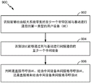
Certain aspects of the present disclosure provide a method for wireless communication by a base station in a network. Generally, the method comprises: identifying a first type of User Equipment (UE) capable of communicating with a base station via at least one narrowband region of a larger system bandwidth; identifying at least one intermediary device through which the UE is capable of indirect communication with the base station; determining whether to page the UE directly, indirectly via the intermediary device, or indirectly directly and via the intermediary device.
Certain aspects of the present disclosure provide an apparatus for wireless communications by a base station. In general, the apparatus includes at least one processor configured to: identifying a first type of User Equipment (UE) capable of communicating with a base station via at least one narrowband region of a larger system bandwidth; identifying at least one intermediary device through which the UE is capable of indirect communication with the base station; determining whether to page the UE directly, indirectly via the intermediary device, or indirectly directly and via the intermediary device. The apparatus typically also includes a memory coupled to the at least one processor.
Certain aspects of the present disclosure provide an apparatus for wireless communication by a base station in a network. Generally, the apparatus comprises: means for identifying a first type of User Equipment (UE) capable of communicating with a base station via at least one narrowband region of a larger system bandwidth; means for identifying at least one intermediary device through which the UE is capable of indirect communication with a base station; means for determining whether to page the UE directly, indirectly via the intermediary device, or indirectly directly and via the intermediary device.
Certain aspects of the present disclosure provide a non-transitory computer-readable medium for wireless communications by a base station. Generally, the non-transitory computer-readable medium includes instructions for: identifying a first type of User Equipment (UE) capable of communicating with a base station via at least one narrowband region of a larger system bandwidth; identifying at least one intermediary device through which the UE is capable of indirect communication with the base station; determining whether to page the UE directly, indirectly via the intermediary device, or indirectly directly and via the intermediary device.
Numerous other aspects are provided, including methods, apparatus, systems, computer program products, and processing systems.
Drawings
Figure 1 is a block diagram conceptually illustrating an example of a wireless communication network, in accordance with certain aspects of the present disclosure.
Fig. 2 conceptually illustrates a block diagram of an example of communication of a base station with User Equipment (UE) in a wireless communication network, in accordance with certain aspects of the present disclosure.
Fig. 3 shows an exemplary frame structure for FDD in LTE.
Fig. 4 shows two exemplary subframe formats with a normal cyclic prefix.
Fig. 5 illustrates an example of a narrowband deployment in a larger system bandwidth, in accordance with certain aspects of the present disclosure.
Fig. 6 illustrates an example wireless communication environment, in accordance with certain aspects of the present disclosure.
Fig. 7 illustrates example operations of a User Equipment (UE), in accordance with certain aspects of the present disclosure.
Fig. 8 illustrates exemplary operation of an apparatus, according to certain aspects of the present disclosure.
Fig. 9 illustrates example operation of a Base Station (BS), in accordance with certain aspects of the present disclosure.
Detailed Description
Aspects of the present disclosure provide various techniques for improving communication of Machine Type Communication (MTC) devices capable of communicating with a network either directly (e.g., via a base station) or indirectly (e.g., via an intermediate device that utilizes device-to-device (D2D) communication). In particular, aspects of the present disclosure provide techniques for improving low power discovery, transitions between direct and relay link communications, and paging of MTC devices.
The techniques described herein may be used for various wireless communication networks such as CDMA, TDMA, FDMA, OFDMA, SC-FDMA and other networks. The terms "network" and "system" are often used interchangeably. A CDMA network may implement a radio technology such as Universal Terrestrial Radio Access (UTRA), CDMA2000, and so on. UTRA includes wideband CDMA (wcdma), time division synchronous CDMA (TD-SCDMA), and other CDMA variations. CDMA2000 covers IS-2000, IS-95 and IS-856 standards. TDMA networks may implement wireless technologies such as global system for mobile communications (GSM). OFDMA networks may implement methods such as evolved UTRA (E-UTRA), Ultra Mobile Broadband (UMB), IEEE 802.11(Wi-Fi), IEEE 802.16(WiMAX), IEEE 802.20, Flash- And so on. UTRA and E-UTRA are generalAs part of a mobile telecommunications system (UMTS). 3GPP Long Term Evolution (LTE) and LTE-advanced (LTE-A) (with both Frequency Division Duplex (FDD) and Time Division Duplex (TDD)) are a new release of UMTS that employs E-UTRA on the downlink using OFDMA and on the uplink using SC-FDMA. UTRA, E-UTRA, UMTS, LTE-A, and GSM are described in documents from an organization named "third Generation partnership project" (3 GPP). CDMA2000 and UMB are described in documents from an organization named "third
 generation partnership project 2" (3GPP 2). The techniques described herein may be used for these wireless networks and the wireless technologies mentioned above as well as other wireless networks and wireless technologies. For clarity of explanation, certain aspects of the techniques are described below for LTE/LTE-advanced, which LTE/LTE-advanced terminology is used in much of the description below. LTE and LTE-A are commonly referred to as LTE.
Fig. 1 illustrates an exemplary wireless communication network 100 in which aspects of the disclosure may be implemented. For example, the techniques presented herein may be used to facilitate communications between the UE and the BS shown in fig. 1 using a narrowband (e.g., six PRB) based search space.
The network 100 may be an LTE network or some other wireless network. Wireless network 100 may include a plurality of evolved node bs (enbs) 110 and other network entities. An eNB is an entity that communicates with User Equipment (UE), and may also be referred to as a base station, a node B, an access point, etc. Each eNB may provide communication coverage for a particular geographic area. In 3GPP, the term "cell" can refer to a coverage area of an eNB and/or an eNB subsystem serving the coverage area, depending on the context in which the term is used.
An eNB may provide communication coverage for a macro cell, pico cell, femto cell, and/or other types of cells. A macro cell may cover a relatively large geographic area (e.g., several kilometers in radius) that allows unrestricted access by UEs with service subscriptions. A pico cell may cover a relatively small geographic area that allows unrestricted access by UEs with service subscriptions. A femto cell may cover a relatively small geographic area (e.g., a home) that allows restricted access by UEs having an association with the femto cell (e.g., UEs in a Closed Subscriber Group (CSG)). The eNB for the macro cell may be referred to as a macro eNB. An eNB for a pico cell may be referred to as a pico eNB. An eNB for a femto cell may be referred to as a femto eNB or a home eNB (henb). In the example shown in fig. 1, eNB 110a may be a macro eNB for macro cell 102a, eNB 110b may be a pico eNB for pico cell 102b, and eNB 110c may be a femto eNB for femto cell 102 c. An eNB may support one or more (e.g., three) cells. The terms "eNB", "base station" and "cell" herein may be used interchangeably.
In addition, the wireless network 100 may also include relay stations. A relay station is an entity that can receive a transmission of data from an upstream station (e.g., an eNB or UE) and send the transmission of the data to a downstream station (e.g., a UE or eNB). The relay station may also be a UE that can relay transmissions of other UEs. In the example shown in fig. 1, relay 110d may communicate with macro eNB 110a and UE 120d to facilitate communication between eNB 110a and UE 120 d. Further, a relay station may also be referred to as a relay eNB, a relay base station, a relay, and so on.
UEs 120 (e.g., 120a, 120b, 120c) may be dispersed throughout wireless network 100, and each UE may be stationary or mobile. A UE may also be called an access terminal, mobile station, subscriber unit, station, or the like. A UE may be a cellular phone, a Personal Digital Assistant (PDA), a wireless modem, a wireless communication device, a handheld device, a laptop computer, a cordless phone, a Wireless Local Loop (WLL) station, a tablet, a smart phone, a netbook, a smartbook, an ultrabook, and so forth. In fig. 1, a solid line with double arrows indicates a desired transmission between a UE and a serving eNB, wherein the serving eNB is an eNB designated to serve the UE on the downlink and/or uplink. The dashed line with double arrows indicates potentially interfering transmissions between the UE and the eNB.
One or more UEs 120 in the wireless communication network 100 (e.g., an LTE network) may also be narrowband bandwidth UEs. These UEs may coexist with legacy UEs and/or advanced UEs in the LTE network (e.g., which are capable of operating over a wider bandwidth), which may have limited capability or capabilities compared to other UEs in the wireless network. For example, in LTE release 12, narrowband UEs may operate in one or more of the following scenarios compared to legacy UEs and/or advanced UEs in LTE networks: a reduction in maximum bandwidth (relative to a legacy UE), a single received Radio Frequency (RF) chain, a reduction in peak rate (e.g., a maximum of 1000 bits of Transport Block Size (TBS) can be supported), a reduction in transmit power, rank 1 transmission, half-duplex operation, and so on. In some cases, if half-duplex operation is supported, the narrowband UE may have loose handover timing from transmit to receive (or from receive to transmit) operation. For example, in one case, a narrowband UE may have a relaxed handover timing of 1 millisecond (ms) compared to a20 microsecond (us) handover timing of legacy UEs and/or advanced UEs.
In some cases, low complexity UEs (e.g., in LTE release 12) are still able to monitor Downlink (DL) control channels in the same manner that legacy UEs and/or advanced UEs in an LTE network monitor DL control channels. A release 12 narrowband UE still monitors the Downlink (DL) control channel in the same way as a regular UE, e.g., a wideband control channel (e.g., Physical Downlink Control Channel (PDCCH)) in the first few symbols, and a narrowband control channel (e.g., enhanced PDCCH (epdcch)) that occupies a relatively narrowband but spans the length of one subframe.
According to certain aspects, when a narrowband UE coexists in a wider system bandwidth (e.g., 1.4/3/5/10/15/20MHz), it may be limited to a particular narrowband allocation of 1.4MHz or six Resource Blocks (RBs) partitioned from the available system bandwidth. In addition, the narrowband UE may also be capable of supporting one or more coverage modes of operation. For example, narrowband UEs can support coverage enhancements of up to 15 dB.
As used herein, a device with limited communication resources (e.g., smaller bandwidth) is generally referred to as a narrowband UE. Similarly, legacy devices such as legacy UEs and/or advanced UEs (e.g., in LTE) are often referred to as wideband UEs. In general, a wideband UE is capable of operating on a greater amount of bandwidth than a narrowband UE.
In some cases, a UE (e.g., a narrowband UE or a broadband UE) may perform cell search and acquisition procedures prior to communicating in a network. In one case, for example, referring to the LTE network shown in fig. 1, when a UE is not connected to an LTE cell and wants to access the LTE network, a cell search and acquisition procedure may be performed. In these cases, the UE may be just powered on, resume connection after temporarily losing connection with the LTE cell, and so on.
In other cases, the cell search and acquisition procedure may be performed when the UE is already connected to an LTE cell. For example, the UE may detect a new LTE cell and prepare to handover to the new cell. As another example, a UE may operate in one or more low power states (e.g., Discontinuous Reception (DRX) may be supported), and thus upon exiting the one or more low power states, a cell search and acquisition procedure must be performed (even though the UE is still in connected mode).
Fig. 2 shows a block diagram of a design of base station/eNB 110 and UE 120, where base station/eNB 110 and UE 120 may be one of the base stations/enbs in fig. 1 and one of the UEs in fig. 1. Additionally, in some cases, the UE 120 may be an intermediate device (e.g., a first tier device as shown in fig. 6) and a Machine Type Communication (MTC) device (e.g., another UE 120, a second tier device as shown in fig. 6). The base station 110 may be equipped with T antennas 234a through 234T and the UE 120 may be equipped with R antennas 252a through 252R, where T ≧ 1 and R ≧ 1.
At base station 110, a transmit processor 220 may receive data for one or more UEs from a data source 212, select one or more Modulation and Coding Schemes (MCSs) for each UE based on the CQIs received from the UE, process (e.g., encode and modulate) the data for each UE based on the selected MCS for the UE, and provide data symbols for all UEs. Transmit processor 220 may also process system information (e.g., for SRPI, etc.) and control information (e.g., CQI requests, grants, upper layer signaling, etc.) and provide overhead symbols and control symbols. Processor 220 can also generate reference symbols for reference signals (e.g., CRS) and synchronization signals (e.g., PSS and SSS). A Transmit (TX) multiple-input multiple-output (MIMO) processor 230 may perform spatial processing (e.g., precoding) on the data symbols, the control symbols, the overhead symbols, and/or the reference symbols, if applicable, and may provide T output symbol streams to T Modulators (MODs) 232a through 232T. Each modulator 232 may process a respective output symbol stream (e.g., for OFDM, etc.) to obtain an output sample stream. Each modulator 232 may further process (e.g., convert to analog, amplify, filter, and upconvert) the output sample stream to obtain a downlink signal. T downlink signals from modulators 232a through 232T may be transmitted via T antennas 234a through 234T, respectively.
At UE 120, antennas 252a through 252r may receive downlink signals from base station 110 and/or other base stations and provide received signals to demodulators (DEMODs) 254a through 254r, respectively. Each demodulator 254 may condition (e.g., filter, amplify, downconvert, and digitize) a respective received signal to obtain input samples. Each demodulator 254 may further process the input samples (e.g., for OFDM, etc.) to obtain received symbols. A MIMO detector 256 may obtain received symbols from all R demodulators 254a through 254R, perform MIMO detection on the received symbols (if any), and provide detected symbols. A receive processor 258 may process (e.g., demodulate and decode) the detected symbols, provide decoded data for UE 120 to a data sink 260, and provide decoded control information and system information to a controller/processor 280. The channel processor may determine RSRP, RSSI, RSRQ, CQI, and so on.
On the uplink, at UE 120, a transmit processor 264 may receive data from a data source 262, receive control information (e.g., for reporting including RSRP, RSSI, RSRQ, CQI, etc.) from a controller/processor 280, and process the data and control information. Further, processor 264 can also generate reference symbols for one or more reference signals. The symbols from transmit processor 264 may be precoded by a TX MIMO processor 266 if applicable, further processed by modulators 254a through 254r (e.g., for SC-FDM, OFDM, etc.), and transmitted to base station 110. At base station 110, the uplink signals from UE 120 and other UEs may be received by antennas 234, processed by demodulators 232, detected by a MIMO detector 236 (if any), and further processed by a receive processor 238 to obtain the decoded data and control information sent by UE 120. Processor 238 may provide the decoded data to a data sink 239 and the decoded control information to controller/processor 240. The base station 110 may include a communication unit 244 and communicate to the network controller 130 via the communication unit 244. Network controller 130 may include a communication unit 294, a controller/processor 290, and a memory 292.
Controllers/ processors 240 and 280 may direct the operation at base station 110 and UE 120, respectively. For example, controller/processor 280 and/or other processors and modules at UE 120 may perform or direct operations 700 shown in fig. 7 and/or operations 800 shown in fig. 8. In addition, for example, the controller/processor 240 and/or other processors and modules at the eNB 110 may perform or direct the operations 900 illustrated in fig. 9. Memories 242 and 282 may store data and program codes for base station 110 and UE 120, respectively, such as instructions/program codes for performing the processes illustrated in the functional blocks of fig. 7, 8, and 9. A scheduler 246 may schedule UEs for data transmission on the downlink and/or uplink.
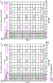
Fig. 3 shows an exemplary frame structure 300 for FDD in LTE. A transmission timeline for each of the downlink and uplink may be divided into units of radio frames. Each radio frame may have a predetermined duration (e.g., 10 milliseconds (ms)) and be divided into 10 subframes with indices of 0 through 9. Each subframe may include two slots. Thus, each radio frame may include 20 slots with indices of 0 through 19. Each slot may include L symbol periods, e.g., seven symbol periods for a normal cyclic prefix (as shown in fig. 3) or six symbol periods for an extended cyclic prefix. Indexes 0 to 2L-1 may be allocated to 2L symbol periods in each subframe.
In LTE, an eNB may transmit Primary Synchronization Signals (PSS) and Secondary Synchronization Signals (SSS) on the downlink in the middle of the system bandwidth for each cell supported by the eNB. The PSS and SSS may be transmitted in symbol periods 6 and 5, respectively, in subframes 0 and 5 of each radio frame with the normal cyclic prefix, as shown in fig. 3. The PSS and SSS may be used by the UE for cell search and acquisition, which may contain information such as a cell ID and an indication of duplex mode. The indication of duplex mode may indicate whether the cell uses Time Division Duplex (TDD) or Frequency Division Duplex (FDD) frame structures. The eNB may transmit cell-specific reference signals (CRSs) in a system bandwidth for each cell supported by the eNB. The CRS may be transmitted in certain symbol periods of each subframe, which may be used by the UE to perform channel estimation, channel quality measurement, and/or other functions. The eNB may also send a Physical Broadcast Channel (PBCH) in symbol periods 0 to 3 in slot 1 of some radio frames. The PBCH may carry some system information. The eNB may transmit other system information, such as System Information Blocks (SIBs), on the Physical Downlink Shared Channel (PDSCH) in certain subframes. The eNB may send control information/data on a Physical Downlink Control Channel (PDCCH) in the first B symbol periods of a subframe, where B is configurable for each subframe. The eNB may transmit traffic data and/or other data on the PDSCH in the remaining symbol periods of each subframe.
The UE may perform channel quality measurements according to a prescribed schedule (e.g., a schedule based on the UE's DRX cycle). For example, the UE may attempt to perform measurements for the serving cell every DRX cycle. In addition, the UE may also attempt to perform measurements for non-serving neighbor cells. Measurements for non-serving neighbor cells may be made based on a different schedule than for the serving cell, and the UE may need to tune away from the serving cell to measure the non-serving cell while the UE is in connected mode.
To facilitate channel quality measurements, the n enbs may transmit cell-specific reference signals (CRSs) on specific subframes. For example, the eNB may transmit CRS on subframes 0 and 5 of a given frame. The narrowband UE may receive the signal and measure the average power or RSRP of the received signal. Further, the narrowband UE may also calculate a Received Signal Strength Indicator (RSSI) based on the total received signal power from all sources. Further, RSRQ may also be calculated based on RSRP and RSSI.
To facilitate measurements, the eNB may provide measurement configurations to UEs located within its coverage area. The measurement configuration may specify event triggers for measurement reporting, and each event trigger may have associated parameters. When the UE detects a configured measurement event, it may respond by sending a measurement report with information about the associated measurement object to the eNB. For example, the configured measurement event may be a measured Reference Signal Received Power (RSRP) or a measured Reference Signal Received Quality (RSRQ) meeting a threshold. A time-to-trigger (TTT) parameter may be used to specify how long a measurement event must last before the UE sends its measurement report. In this way, the UE may signal the network of a change in its radio conditions.
Fig. 4 shows two exemplary subframe formats 410 and 420 for a common cyclic prefix. The available time-frequency resources may be divided into resource blocks. Each resource block may cover 12 subcarriers in one slot, and each resource block may include a plurality of resource units. Each resource element may cover a subcarrier in a symbol period and may be configured to transmit a modulation symbol, which may be a real or complex value.
Under the heading "Evolved Universal Radio Access (E-UTRA); in 3GPP TS 36.211 of Physical Channels and Modulation ", PSS, SSS, CRS and PBCH in LTE are described, wherein the document is publicly available.
For each of the downlink and uplink for FDD in LTE, an interleaving structure may be used. For example, Q interlaces may be specified with indices of 0 through Q-1, where Q may be equal to 4, 6, 8, 10, or some other value. Each interlace may include subframes separated by Q frames. Specifically, interlace Q may include subframe Q, Q + Q, Q +2Q, etc., where Q ∈ { 0., Q-1 }.
The wireless network may support hybrid automatic repeat request (HARQ) for data transmission on the downlink and uplink. For HARQ, a transmitter (e.g., an eNB) may send one or more transmissions of a packet until the packet is decoded correctly by a receiver (e.g., a UE), or some other termination condition is met. For synchronous HARQ, all transmissions for the packet may be sent in subframes of a single interlace. For asynchronous HARQ, each transmission of the packet may be sent in any subframe.
The UE may be located within the coverage of multiple enbs. One of the enbs may be selected to serve the eNB. The serving eNB may be selected based on various criteria such as received signal strength, received signal quality, path loss, and so on. The received signal quality may be quantified by a signal-to-noise-plus-interference ratio (SINR), or a Reference Signal Received Quality (RSRQ), or some other metric. The UE may operate in a dominant interference scenario where the UE observes strong interference from one or more interfering enbs.
The focus of the conventional LTE design is to improve spectral efficiency, provide ubiquitous coverage, and enhanced quality of service (QoS) support. Current LTE system Downlink (DL) and Uplink (UL) link budgets are designed for the coverage of high-end devices, such as state-of-the-art smartphones and tablets, which may support relatively large DL and UL link budgets.
Thus, as described above, one or more UEs in a wireless communication network (e.g., wireless communication network 100) may be devices (e.g., narrowband UEs) that have limited communication resources compared to other (broadband) devices in the wireless communication network. For narrowband UEs, various requirements may be relaxed since only a limited amount of information needs to be exchanged. For example, the maximum bandwidth may be reduced (relative to a wideband UE), a single receive Radio Frequency (RF) chain may be used, the peak rate may be reduced (e.g., a maximum transport block size of 1000 bits), the transmit power may be reduced, rank 1 transmission may be used, and half-duplex operation may be performed.
In some cases, if half-duplex operation is performed, the narrowband UE may have a relaxed switching time to transition from transmit to receive operation (or from receive to transmit operation). For example, the switching time may be relaxed from 20 μ s for regular UEs to 1ms for narrowband UEs. A release 12 narrowband UE may still monitor the Downlink (DL) control channel in the same manner as a regular UE, e.g., monitoring a wideband control channel (e.g., PDCCH) in the first few symbols, and a narrowband control channel (e.g., ePDCCH) that occupies a relatively narrowband but spans the length of one subframe.
In some systems, e.g., in LTE Rel-13, narrowband UEs may be restricted to a particular narrowband allocation (e.g., having no more than six Resource Blocks (RBs)) within the available system bandwidth. However, the narrowband UE can retune (e.g., operate and/or camp on) to a different narrowband region in the available system bandwidth of the LTE system, e.g., to co-exist in the LTE system.
As another example of coexistence in an LTE system, a narrowband UE may be able to receive (with repetition) a legacy Physical Broadcast Channel (PBCH) (e.g., an LTE physical channel that typically carries parameters that may be used for initial access of a cell) and support one or more legacy Physical Random Access Channel (PRACH) formats. For example, the narrowband UEs may be capable of receiving a legacy PBCH with one or more additional repetitions of the PBCH across multiple subframes. As another example, a narrowband UE may be able to transmit one or more repetitions of a PRACH (e.g., with one or more PRACH formats supported) to an eNB in an LTE system. The PRACH may be used to identify narrowband UEs. Further, the eNB may configure the number of repeated PRACH attempts.
Further, narrowband UEs may also be link budget limited devices and may operate in different modes of operation based on their link budget limits (e.g., requiring different amounts of repeated messages to be sent to the narrowband UE). For example, in some cases, a narrowband UE may operate in a normal coverage mode where there is little repetition (i.e., the amount of repetition required for the UE to successfully receive a message may be low or may not even require repetition). Alternatively, in some cases, a narrowband UE may operate in a Coverage Enhancement (CE) mode, where there may be a large number of repetitions. For example, for a 328-bit payload, a narrowband UE in CE mode may require 150 or more payload repetitions to successfully receive the payload.
In some cases, for example, for LTE Rel-13, narrowband UEs may have limited capabilities with respect to reception of broadcast and unicast transmissions. For example, the maximum Transport Block (TB) size of a broadcast transmission received by a narrowband UE may be limited to 1000 bits. In addition, in some cases, a narrowband UE may not be able to receive more than one unicast TB in a subframe. In some cases (e.g., for the CE mode and the normal mode described above), a narrowband UE may not be able to receive more than one broadcast TB in one subframe. Furthermore, in some cases, a narrowband UE may not be able to receive both unicast TBs and broadcast TBs in one subframe.
Narrowband UEs that coexist in an LTE system may also support new messages (e.g., compared to conventional messages used for certain procedures in LTE) for certain procedures (e.g., paging, random access procedures, etc.). In other words, these new messages for paging, random access procedures, and so on may be separate from messages for similar procedures associated with non-narrowband UEs. For example, narrowband UEs may be able to monitor and/or receive paging messages that non-narrowband UEs may not be able to monitor and/or receive, as compared to conventional paging messages used in LTE. Similarly, a narrowband UE can receive a Random Access Response (RAR) message that may or may not be received by a non-narrowband UE, as compared to a conventional RAR message used in a conventional random access procedure. The new paging and RAR messages associated with the narrowband UE may also be repeated one or more times (e.g., "bundled"). In addition, different numbers of repetitions of the new message (e.g., different bundle sizes) may be supported.
According to certain aspects, multiple narrowband regions may be supported by narrowband UEs and/or narrowband operations, where each narrowband region spans a bandwidth of no more than 6 total RBs. In some cases, each narrowband UE in narrowband operation may operate within one narrowband region (e.g., at 1.4MHz or 6 RBs) at a time. However, a narrowband UE in narrowband operation may retune to other narrowband regions in the wider system bandwidth at any given time. In some examples, multiple narrowband UEs may be served by the same narrowband region. In other examples, multiple narrowband UEs may be served by different narrowband regions (e.g., each narrowband region spanning 6 RBs). In other examples, different combinations of narrowband UEs may be served by one or more of the same narrowband region and/or one or more different narrowband regions.
Some systems (e.g., in LTE Rel-13) introduce coverage enhancements and support for narrowband UEs as well as other UEs. As used herein, the term coverage enhancement generally refers to any type of mechanism that extends the coverage of a device (e.g., a narrowband device) in a network. One method for Coverage Enhancement (CE) is bundling, which refers to transmitting the same data multiple times (e.g., across multiple subframes or across multiple symbols in the same subframe (as described in further detail below)).
In some systems, narrowband UEs may support narrowband operation where they may operate in a wider system bandwidth. For example, a narrowband UE may transmit and receive in a narrowband region of the system bandwidth. As described above, the narrowband region may span 6 Resource Blocks (RBs).
Some systems may provide coverage enhancement to narrowband UEs of up to 15dB, which maps to a maximum coupling loss of 155.7dB between the UE and the eNB. Thus, the narrowband UE and eNB may perform measurements at low SNR (e.g., -15dB to-20 dB). In some systems, coverage enhancements may include channel bundling, where messages associated with narrowband UEs may be repeated (e.g., bundled) one or more times.
Some devices are capable of communicating in both legacy-type communications and non-legacy-type communications. For example, some devices may be able to communicate in a narrowband region (of the overall system bandwidth) as well as a wider band region. While the above examples refer to low cost or MTC devices communicating over a narrowband region, other (non-low cost/non-MTC) types of devices may also communicate via a narrowband region (e.g., utilizing frequency selective and directional transmissions).
In some cases, some UEs (e.g., Machine Type Communication (MTC) UEs) may have a low cost, low bandwidth design (e.g., operating on a narrower bandwidth than used by UEs with higher capability designs) that need not be backward compatible with GSM or EDGE technology. However, in some cases, these low-cost, low-power UEs ("narrowband UEs") may be compatible with broadband UEs, deployed in-band (i.e., narrowband UEs operating within the bandwidth used by the broadband UE) and deployed independently (i.e., narrowband UEs operating outside the bandwidth used by the broadband UE) using the same or similar design.
For some cases in extreme coverage scenarios, a Minimum Coupling Loss (MCL) of 164dB may be required. The design may be power efficient, support a large number of devices, and may be implemented at low cost. In some cases, a200 kHz channel bandwidth may be used for communication for narrowband UEs.
Fig. 5 illustrates various deployment scenarios in which a narrowband may be deployed within a larger system bandwidth. As shown, the narrowband may be a single LTE resource block with a 180kHz bandwidth and a20 kHz guard band. By using a single LTE resource block for narrowband communications, the higher layers of the LTE stack and most of the hardware can be reused. In addition, the narrowband UE may implement enhanced machine type communication (eMTC) and narrowband LTE, which may avoid fragmentation. As shown, these narrow bands may at least partially overlap with the system bandwidth (e.g., the system bandwidth used by the wideband UE) or may exist outside of the system bandwidth.
In one case, as illustrated by deployment 502, the narrowband can be deployed within a system bandwidth (e.g., within the system bandwidth used by the wideband UE) and dedicated for use by the narrowband UE. Resource blocks in a wideband channel may be used for narrowband communications. In another case, the narrowband can be deployed within a guard band outside (or between) different channels, as shown in deployment 504. In another case, although not shown, the narrowband channel may be a stand-alone channel. For example, a narrowband channel for communication of a narrowband UE may be deployed in the GSM spectrum, using a single 200kHz carrier. As shown, in some cases, certain subsets of subframes 506 may be allocated for narrowband transmissions. The subset of subframes 506 used for narrowband transmissions may be distributed over the system bandwidth. In some casesAs shown, a first subset 506 of subframes1May be associated with other subsets of the sub-frames 506 (e.g., the second subset of sub-frames 506)2) Partially overlapping.
In communication between a UE and an enodeb (enb), the UE typically performs transmissions on a Physical Random Access Channel (PRACH). The eNB detects PRACH transmission, sends a timing advance command, and the UE sends information on a Physical Uplink Shared Channel (PUSCH), which may have a minimum allocation of 1 Resource Block (RB).
In some aspects, a narrowband UE may use 1RB to perform PRACH transmission, which reduces time resolution relative to PRACH transmission sent using a wider bandwidth. The temporal resolution for the wider bandwidth of 6 RBs may be about 1 microsecond, while the temporal resolution for the narrow band of 1RB may be about 5 microseconds. The timing advance command may lose accuracy due to the reduced time resolution and potentially lower signal to noise ratio of the 1RB narrow band. In some cases, UEs in deep coverage may be power limited (i.e., unable to benefit from additional bandwidth), which may allow the use of sub-RB allocations to increase multiplexing capability for narrowband communications (e.g., 1RB bandwidth LTE communications).
In one design, the uplink numerology of a wideband LTE subframe may be multiplied by a factor of 6 to enable narrowband LTE communications. Each symbol and cyclic prefix may be six times longer with a subcarrier spacing of 2.5 kHz. Multiplying the uplink numerology may result in higher time inaccuracy without loss of efficiency (in terms of overhead), which may allow multiplexing of a large number of UEs at the same time. However, multiplying the uplink digital scheme by a factor of 6 may cause the narrowband LTE transmissions to lose orthogonality with the wideband (legacy) LTE transmissions, which may result in additional interference. If the wideband UE and the narrowband UE are time multiplexed in the same RB, the additional cyclic prefix length may not be able to compensate for the timing advance error. Finally, the difference between scheduling time units for narrowband and wideband UEs may cause problems for scheduling, time domain duplex operation, and multiplexing narrowband LTE PUSCH with wideband sounding reference signals.
In some cases, the narrowband LTE transmissions and the wideband LTE transmissions may use the same subframe structure and digital scheme.
Exemplary D2D communication for eMTC design solution considerations
Aspects of the present disclosure provide various techniques for improving communication of Machine Type Communication (MTC) devices capable of communicating with a network either directly (e.g., via a base station) or indirectly (e.g., via an intermediate device that utilizes device-to-device (D2D) communication). In particular, aspects of the present disclosure provide techniques for improving low power discovery, transitions between direct and relay link communications, and paging of MTC devices.
Fig. 6 illustrates an example wireless communication environment in which aspects of the disclosure may be implemented. As shown, the wireless communication environment may include a plurality of communication layers (e.g., a first layer and a second layer). By way of example, the first communication layer may include low power devices (e.g., Remote Radio Heads (RRHs), small cells, smart phones, MTC hubs), and in some cases may include MTC devices that communicate directly with the network (e.g., via macro cells). The second communication layer may include MTC devices capable of communicating with the network via intermediate devices (e.g., first layer devices), for example, using D2D and/or a WAN.
As described above, there may be different ways (e.g., direct or indirect) in which MTC devices can communicate with the network. As an example, MTC devices may operate in relay/D2D mode. For example, after detecting an intermediate device providing/capable of providing a service to the MTC device, the MTC device may connect to the network through the intermediate device. In some cases, communicating with the network through the intermediary device may help conserve power on the MTC device, thereby extending the battery life of the MTC device.
However, in this case (i.e. in relay/D2D mode), there may be two entities with different Subscriber Identity Module (SIM) cards. Therefore, in this case, there is a problem as to how to handle the continuity of the connection between the MTC device and the network, as explained in further detail below.
In addition, MTC devices may communicate with the network through HUB devices via different types of wireless technologies. For example, in some cases, an MTC device may establish with an intermediate device Or a WiFi connection and may then communicate with the network through the intermediary device.
However, in some cases, when an intermediate device capable of providing services to MTC devices is not in the vicinity of the MTC device, the MTC device may be directly connected to the network, for example via a base station such as an evolved node b (enb).
However, there are certain problems in the case where MTC devices are able to communicate with the network through intermediate devices and/or communicate directly with the network. For example, there are issues regarding how MTC devices should perform low power discovery, how to transition between direct communication with the network and communication through an intermediate device, and how to handle paging. Accordingly, aspects of the present disclosure provide techniques for solving these problems.
To begin communicating with the network, the MTC device may need to perform a discovery procedure to determine whether there are any nearby devices (e.g., intermediate devices) through which to communicate. Subsequently, the MTC device may determine whether to communicate directly with the network or indirectly with the network using an intermediate device.
Fig. 7 illustrates exemplary operations 700 for wireless communication. According to certain aspects, exemplary operations 700 may be performed by a first type of User Equipment (UE) (e.g., MTC device) capable of communicating with a network via at least one narrowband region of a larger system bandwidth.
According to certain aspects, MTC devices may search for Primary Synchronization Signals (PSS), Secondary Synchronization Signals (SSS), and/or physical broadcast channels from surrounding enbs for direct communication with the network. To communicate with the network through the intermediary device, the MTC device may search for a discovery signal from the probe device. If the MTC device decides to initiate a connection, the MTC device may perform a Radio Access Channel (RACH) procedure for direct communication with the network and a D2D communication setup for communication through an intermediate device.
According to certain aspects, for MTC devices within the coverage area of an eNB and capable of receiving service from the eNB, as described above, the MTC devices may perform a RACH procedure and Radio Resource Control (RRC) connection establishment with the eNB. Alternatively, the MTC device may be connected by the HUB device (e.g., communicating via D2D) and indicate that the MTC device is in-band.
For MTC devices out of coverage (e.g., which are not able to receive service directly from the eNB), the MTC devices may connect with the intermediate device instead of performing a RACH procedure. According to certain aspects, during D2D connection establishment, the MTC device may indicate (e.g., to the intermediate device) that it is not associated with any eNB. For initial connectivity, the MTC device may search for a pre-provisioned discovery signal from the intermediate device. Once the MTC device establishes a connection with the intermediary device, the intermediary device may relay connection establishment information for the MTC device to the network.
To establish a connection with an intermediate device, as described above, the MTC device may need to perform a short-range low-power discovery procedure to discover the intermediate device to which the MTC device can connect. The discovery process may involve searching for discovery signals (e.g., enbs and/or intermediate devices) transmitted by nearby devices.
Fig. 8 illustrates exemplary operations 800 for wireless communication in a network. According to certain aspects, the example operations 800 may be performed by, for example, an apparatus for transmitting a discovery signal (e.g., an intermediary).
According to certain aspects, there may be specific connection settings (e.g., using specific D2D connection parameters) between the intermediary device and the MTC device. For example, after initial setup, the MTC device may always search only for a particular signature sequence associated with the intermediate device. In some cases, the initial connection may be performed over a network. For example, an MTC device may be connected to an eNB, and the eNB may provide D2D configuration information (e.g., parameters) to the MTC device for establishing a connection between the MTC device and an intermediate device. Additionally, transmissions between the intermediary device and the MTC device may have a fixed periodicity, which may be pre-negotiated and targeted for latency and/or power requirements of the MTC/intermediary device. In other words, parameters such as transmission period, target delay, and/or power requirements may be negotiated and used in advance when communicating between the MTC device and the intermediate device.
According to certain aspects, transmission of a discovery signal for establishing a connection may be performed differently between an intermediate device and an MTC device according to a coverage condition. For example, if the MTC device is within the coverage of the eNB, the intermediate device may periodically transmit a discovery signal, and the MTC device may perform a search for the discovery signal. According to certain aspects, this option may support multiple MTC devices. The MTC device may send a signature sequence if the MTC device is out of coverage. In this case, the intermediary must perform a search for these signature sequences on a periodic basis.
According to certain aspects, there may be two communication links when the device acts as an intermediary between the network and the MTC device. For example, the first link may comprise a link between the intermediate device and an eNB, which involves conventional LTE type communications. The second link may comprise a D2D link/communication between the intermediate device and the MTC device (e.g., in some cases, and/or WiFi).
There are certain design options between these two links. For example, the first link and the second link may remain independent. Under this design, Acknowledgement (ACK)/Negative Acknowledgement (NACK) only focuses on link quality on the first link. According to certain aspects, the design may be equivalent to a "layer 2" (or higher) relay. In another design, the first link and the second link may be joint, where ACK/NACK focuses on success between the MTC device and the eNB. According to certain aspects, the design is equivalent to a "layer 1" relay.
According to certain aspects, as described above, the MTC device may need to decide whether to send its traffic directly to the network (e.g., via an eNB) or through an intermediate device (e.g., using D2D communication). As part of this decision, the MTC device may consider the quality of the communication link between the MTC device and the eNB and the quality of the communication link between the intermediate device and the eNB. For example, the MTC device may measure the quality of the link between the intermediate device and itself and the quality of the link between itself and the eNB.
According to certain aspects, the MTC device may also determine to connect to and/or camp on the eNB or the intermediate device based on the quality of the communication link between the intermediate device and the eNB. However, the MTC device cannot measure the quality, and thus must receive quality information from an intermediate device or a network. For example, according to certain aspects, the intermediate device may broadcast quality information (i.e., the quality of the signal between the HUB device and the eNB) in the D2D discovery channel (e.g., within the discovery signal). The MTC device may receive this quality information and decide whether to connect to and/or camp on the eNB or on an intermediate device, e.g., based on which signal (i.e., the signal between the MTC device and the eNB or the signal between the HUB device and the eNB) is better. For example, if the signal between the MTC device and the eNB is better, the MTC device may decide to connect directly to the network via the eNB, whereas if the signal between the intermediate device and the eNB is better, the MTC device may choose to connect to the network via the intermediate device.
In addition, the intermediate device may also broadcast resources (e.g., also within the discovery signal) that may be used for D2D communication, and depending on these resources, the MTC device may decide whether to connect to and/or camp on the eNB or the intermediate device. For example, if D2D communication provides a lower data rate than what MTC devices need, the MTC devices may decide to connect to the eNB rather than communicate through an intermediate device.
Additionally or alternatively, when the signal between the intermediate device and the eNB falls below a certain threshold, the intermediate device (e.g., HUB) may decide to close the D2D connection between it and the MTC device so that the MTC device only "sees" the eNB. In this case, assuming that no other intermediate device is in the vicinity of the MTC device, the MTC device may be directly connected to the network via the eNB. However, if other intermediate devices are located in the vicinity of the MTC device, the MTC device may choose to connect with the other intermediate devices for communication with the network.
According to certain aspects, previous solutions to determining whether to signal directly to an eNB or via an intermediary device may be independent of a Radio Access Technology (RAT) used for D2D connection (e.g., LTE-Direct, WiFi, or some other suitable technique, Etc.) to operate.
According to certain aspects, when connected to an intermediate device, the MTC device should not declare a Radio Link Failure (RLF) as long as the MTC device is able to discover a nearby D2D device (e.g., another intermediate device) that may be linked to the network. If there are other intermediate devices in the vicinity of the MTC device, the MTC device may be handed over from one intermediate device to another in order to maintain a connection with the network.
As described above, for an MTC device connected to a network through an intermediate device, for example, there may be a problem how to perform paging. For example, a network may want to page MTC devices in an idle state, but MTC devices may want to connect to the network through an intermediate device. Therefore, there may be a problem of how the network should page the MTC devices.
Fig. 9 illustrates exemplary operations 900 of wireless communication that facilitate mitigating paging issues determined above for MTC devices. According to certain aspects, operation 900 may be performed by, for example, a base station.
According to certain aspects, to help alleviate the paging problem, one solution may involve the MTC device selecting two devices to communicate with the network: the best eNB for LTE communication and the best intermediate device for D2D communication. Subsequently, the MTC device may receive a page from the eNB, and may connect to the network through the intermediate device.
According to certain aspects, in another solution, if an MTC device is camped on an intermediary device, the MTC device may notify the network of the intermediary device on which the MTC device is camped. Subsequently, the eNB may send a page to the intermediary, which in turn forwards the page to the MTC device. However, in some cases, there may be more than one intermediate device that forwards pages to the MTC device. In this case, the page from each intermediary device may be different and the MTC device may connect to the intermediary device from which the page was received. Additionally or alternatively, the MTC device may receive a Single Frequency Network (SFN) page (e.g., a page transmitted simultaneously from all intermediate devices), may connect to the intermediate device with the best signal quality (e.g., between the MTC device and the intermediate device and/or between the intermediate device and the eNB).
In some cases, a user may have an MTC device and an intermediary device (e.g., a smartphone) with the same number but different UE IDs (since the two devices may have different SIM cards). However, the network may not know whether the user is carrying MTC devices and/or intermediate devices, so the network may not know which device to page to and establish a call with. According to certain aspects, the network may page the MTC device and the intermediate device simultaneously, forcing the two devices to ring simultaneously. Once the user answers one of the calls on the MTC device or the intermediate device, the call on the other device is automatically dropped. In some cases, the network may page the intermediary first and if the user does not answer the intermediary, the network may then page the MTC device. In other cases, information regarding whether the user owns the MTC device and the intermediary device may be provided to the network (e.g., by the intermediary device and/or the MTC device). In this case, the network may decide whether to page the intermediate device or the MTC device.
Those of skill in the art would understand that information and signals may be represented using any of a variety of different technologies and techniques. For example, data, instructions, commands, information, signals, bits, symbols, and chips that may be referenced throughout the above description may be represented by voltages, currents, electromagnetic waves, magnetic fields or particles, optical fields or particles, or any combination thereof.
The various operations of the methods described above may be performed by any suitable means capable of performing the corresponding functions. These units may include various hardware and/or software components and/or modules, including but not limited to: a circuit, an Application Specific Integrated Circuit (ASIC), or a processor. Generally, where operations are illustrated in the figures, the operations may have corresponding paired functional module components containing similar numbering.
For example, the performing unit, the deciding unit, the judging unit, the searching unit, the negotiating unit, the changing unit (e.g., communication), the modifying unit (e.g., radio link monitoring), the monitoring unit, the taking action unit, the establishing unit, the determining unit, the serving unit, the identifying unit, the maintaining unit, the paging unit, the releasing unit and/or the measuring unit may comprise a processing system, which may comprise one or more processors, e.g., the controller/processor 280 of the user equipment 120 shown in fig. 2 and/or the controller/processor 240 of the eNodeB110 shown in fig. 2. Additionally, the transmitting unit, the receiving unit, the providing unit and/or the communicating unit may comprise one or more antennas, e.g. an antenna of the eNodeB110 or an antenna 252 of the user equipment 120.
Those of ordinary skill would further appreciate that the various illustrative logical blocks, modules, circuits, and algorithm steps described in connection with the disclosure herein may be implemented as electronic hardware, software/firmware, or combinations of both. To clearly illustrate this interchangeability of hardware and software/firmware, various illustrative components, blocks, modules, circuits, and steps have been described above generally in terms of their functionality. Whether such functionality is implemented as hardware or software/firmware depends upon the particular application and design constraints imposed on the overall system. Skilled artisans may implement the described functionality in varying ways for each particular application, but such implementation decisions should not be interpreted as causing a departure from the scope of the present invention.
A general purpose processor, a Digital Signal Processor (DSP), an Application Specific Integrated Circuit (ASIC), a Field Programmable Gate Array (FPGA) or other programmable logic device, discrete gate or transistor logic, discrete hardware components, or any combination thereof, configured to perform the functions described herein, may be used to implement or perform the various illustrative logical blocks, modules, and circuits described in connection with the disclosure herein. A general-purpose processor may be a microprocessor, but in the alternative, the processor may be any conventional processor, controller, microcontroller, or state machine. A processor may also be implemented as a combination of computing devices, e.g., a combination of a DSP and a microprocessor, a number of microprocessors, one or more microprocessors in conjunction with a DSP core, or any other such configuration.
The steps of a method or algorithm described in connection with the disclosure herein may be embodied directly in hardware, in a software/firmware module executed by a processor, or in a combination of the two. A software/firmware module may reside in RAM memory, flash memory, ROM memory, EPROM memory, EEPROM memory, phase change memory, registers, a hard disk, a removable disk, a CD-ROM, or any other form of storage medium known in the art. An exemplary storage medium may be coupled to the processor such the processor can read information from, and write information to, the storage medium. In the alternative, the storage medium may be integral to the processor. The processor and the storage medium may reside in an ASIC. The ASIC may reside in a user terminal. Of course, the processor and the storage medium may reside as discrete components in a user terminal.
In one or more exemplary designs, the functions described herein may be implemented in hardware, software/firmware, or a combination thereof. When implemented in software/firmware, the functions may be stored on or transmitted over as one or more instructions or code on a computer-readable medium. Computer-readable media includes both computer storage media and communication media including any medium that facilitates transfer of a computer program from one place to another. A storage media may be any available media that can be accessed by a general purpose or special purpose computer. By way of example, and not limitation, such computer-readable media can comprise RAM, ROM, EEPROM, CD/DVD or other optical disk storage, magnetic disk storage or other magnetic storage devices, or any other medium that can be used to carry or store desired program code means in the form of instructions or data structures and that can be accessed by a general-purpose or special-purpose computer, or a general-purpose or special-purpose processor. Also, any connection is properly termed a computer-readable medium. For example, if the software/firmware is transmitted from a website, server, or other remote source using a coaxial cable, fiber optic cable, twisted pair, Digital Subscriber Line (DSL), or wireless technologies such as infrared, radio, and microwave, then the coaxial cable, fiber optic cable, twisted pair, DSL, or wireless technologies such as infrared, radio, and microwave are included in the definition of medium. Disk and disc, as used herein, includes Compact Disc (CD), laser disc, optical disc, Digital Versatile Disc (DVD), floppy disk and blu-ray disc where disks usually reproduce data magnetically, while discs reproduce data optically with lasers. Combinations of the above should also be included within the scope of computer-readable media.
As used herein (which includes the claims), when the term "and/or" is used in a list of two or more items, it means that any one of the listed items is used, or any combination of two or more of the listed items is used. For example, if a complex is described as containing component A, B and/or C, the complex can contain only A; only B is contained; only C is contained; a combination of A and B; a combination of A and C; a combination of B and C; or a combination of A, B and C. Further, as used herein (which includes the claims), a "or" (e.g., a list item ending in a phrase such as "at least one of" or "one or more of") as used in the list item indicates an inclusive list such that, for example, the list "A, B or at least one of C" means: a or B or C or AB or AC or BC or ABC (i.e., A and B and C).
The previous description is provided to enable any person skilled in the art to make or use the present disclosure. Various modifications to the disclosure will be readily apparent to those skilled in the art, and the generic principles defined herein may be applied to other variations without departing from the spirit or scope of the disclosure. Thus, the disclosure is not intended to be limited to the examples and designs described herein but is to be accorded the widest scope consistent with the principles and novel features disclosed herein.
Claims (27)
1. A method for wireless communications by a User Equipment (UE) in a network, comprising:
performing a discovery process to identify one or more intermediary devices through which the UE is capable of communicating indirectly with a base station in the network;
receiving, from an intermediary device identified through the discovery process, information comprising at least a signal strength between the intermediary device and the base station, wherein the information is received in a discovery signal from the intermediary device; and
determining whether to communicate directly with the base station via at least one narrowband region of larger system bandwidth or indirectly with the network via the intermediary device based on one or more criteria,
wherein the one or more criteria include:
a criterion relating to the signal strength between the intermediate device and the base station, an
A standard involving resources available at the intermediate device for device-to-device (D2D) communication, the resources available at the intermediate device including at least a data rate available for the D2D communication, and
wherein the received information further comprises an indication of the resources available at the intermediary device for D2D communication.
2. The method of claim 1, wherein the one or more criteria comprise at least one of:
whether the discovery process identifies an intermediary device proximate to the UE;
a criterion relating to signal strength between the UE and the base station; or
A criterion relating to signal strength between the UE and an intermediate device.
3. The method of claim 1, wherein the one or more intermediary devices comprise at least one of: a telephone, a low power base station, a remote radio head, or a hub device that also communicates with the base station via at least one narrowband region of a larger system bandwidth.
4. The method of claim 1, wherein the discovery process involves at least one of:
searching for synchronization signals from one or more cells;
searching for discovery signals from one or more intermediary devices; or
A predefined discovery signal from one or more intermediary devices is searched.
5. The method of claim 1, further comprising:
negotiating one or more parameters to perform the discovery process.
6. The method of claim 1, further comprising:
performing a device-to-device (D2D) connection setup with an intermediary device if it is decided to communicate indirectly with the base station via the intermediary device.
7. The method of claim 1, further comprising:
performing a Random Access Channel (RACH) procedure if it is decided to communicate directly with the base station.
8. The method of claim 1, wherein how the discovery process is performed depends on whether the UE is within a coverage area of the base station.
9. The method of claim 1, further comprising:
from communicating directly with a base station of the network to communicating indirectly with the network via an intermediate device.
10. The method of claim 9, wherein the change is caused by at least one of:
a measured link quality between the UE and the intermediate device;
a measured link quality between the UE and the base station; or
A measured link quality between the intermediate device and the base station.
11. The method of claim 1, wherein the discovery is not performed if a link quality between the intermediate device and the base station is below a threshold level.
12. The method of claim 1, further comprising changing a radio link monitoring procedure based on a result of the discovery procedure, wherein the change to the radio link monitoring comprises: declaring a radio link failure according to the result of the discovery process.
13. The method of claim 1, further comprising:
taking action to handover the UE between the identified intermediate devices during the discovery process.
14. The method of claim 1, further comprising:
receiving a page from the network, wherein the page is received via the intermediary or directly from the base station.
15. The method of claim 14, further comprising:
establishing a connection with the intermediary device in response to the page received directly from the base station.
16. A method for wireless communications by an apparatus in a network, comprising:
determining one or more parameters for a discovery process to allow a first type of User Equipment (UE) capable of communicating with a base station in the network via at least one narrowband region of a larger system bandwidth to discover the apparatus;
measuring an indicator of signal quality from the device to the base station while avoiding transmission of the discovery signal; and
transmitting a discovery signal in accordance with the determined one or more parameters, wherein transmitting the discovery signal includes transmitting an indicator of the signal quality in at least one of the discovery signals, wherein transmitting the discovery signal further includes transmitting an indication of resources available at the apparatus for device-to-device (D2D) communication, the resources available at the apparatus including at least a data rate available for the D2D communication.
17. The method of claim 16, wherein the determining comprises: and negotiating with the UE.
18. The method of claim 16, wherein the one or more parameters comprise at least one of: a predetermined discovery sequence or timing of discovery signal transmission.
19. The method of claim 16, further comprising:
establishing a connection with the UE; and
act as an intermediary that allows the UE to communicate indirectly with the base station via the apparatus.
20. An apparatus for wireless communications by a User Equipment (UE), comprising:
at least one processor configured to:
performing a discovery process to identify one or more intermediary devices through which the UE is capable of communicating indirectly with a base station of a network;
receiving, from an intermediary device identified through the discovery process, information comprising at least a signal strength between the intermediary device and the base station, wherein the information is received in a discovery signal from the intermediary device; and
determining whether to communicate directly with the base station via at least one narrowband region of larger system bandwidth or indirectly with the network via the intermediary device based on one or more criteria,
wherein the one or more criteria include:
a criterion relating to the signal strength between the intermediate device and the base station, an
A standard involving resources available at the intermediate device for device-to-device (D2D) communication, the resources available at the intermediate device including at least a data rate available for the D2D communication, and
wherein the received information further comprises an indication of the resources available at the intermediary device for D2D communication; and
a memory coupled with the at least one processor.
21. The apparatus of claim 20, wherein the one or more criteria comprise at least one of:
whether the discovery process identifies an intermediary device proximate to the UE;
a criterion relating to signal strength between the UE and the base station; or
A criterion relating to signal strength between the UE and an intermediate device.
22. The apparatus of claim 20, wherein the at least one processor is further configured to:
performing a device-to-device (D2D) connection setup with an intermediary device if it is decided to communicate indirectly with the base station via the intermediary device.
23. The apparatus of claim 20, wherein the at least one processor is further configured to:
from communicating directly with a base station of the network to communicating indirectly with the network via an intermediate device.
24. The apparatus of claim 23, wherein the change is caused by at least one of:
a measured link quality between the UE and the intermediate device;
a measured link quality between the UE and the base station; or
A measured link quality between the intermediate device and the base station.
25. An apparatus for wireless communication, comprising:
at least one processor configured to:
determining one or more parameters for a discovery process to allow a first type of User Equipment (UE) capable of communicating with a base station network via at least one narrowband region of a larger system bandwidth to discover the apparatus;
measuring an indicator of signal quality from the device to the base station while avoiding transmission of the discovery signal; and
transmitting discovery signals according to the determined one or more parameters, wherein to transmit the discovery signals, the at least one processor is configured to transmit an indicator of the signal quality in at least one of the discovery signals and to transmit an indication of resources available at the apparatus for device-to-device (D2D) communication, the resources available at the apparatus including at least a data rate available for the D2D communication; and
a memory coupled with the at least one processor.
26. The apparatus of claim 25, wherein the one or more parameters comprise at least one of: a predetermined discovery sequence or timing of discovery signal transmission.
27. The apparatus of claim 25, wherein the at least one processor is further configured to:
establishing a connection with the UE; and
act as an intermediary that allows the UE to communicate indirectly with the base station via the apparatus.
Applications Claiming Priority (5)
| Application Number | Priority Date | Filing Date | Title |
|---|---|---|---|
| US201562243635P | 2015-10-19 | 2015-10-19 | |
| US62/243,635 | 2015-10-19 | ||
| US15/260,997 US10524108B2 (en) | 2015-10-19 | 2016-09-09 | D2D communication for eMTC design considerations |
| US15/260,997 | 2016-09-09 | ||
| PCT/US2016/051247 WO2017069866A1 (en) | 2015-10-19 | 2016-09-12 | D2D COMMUNICATION FOR eMTC DESIGN CONSIDERATIONS |
Publications (2)
| Publication Number | Publication Date |
|---|---|
| CN108141740A CN108141740A (en) | 2018-06-08 |
| CN108141740B true CN108141740B (en) | 2021-03-16 |
Family
ID=58525940
Family Applications (1)
| Application Number | Title | Priority Date | Filing Date |
|---|---|---|---|
| CN201680060760.9A Active CN108141740B (en) | 2015-10-19 | 2016-09-12 | D2D communication for eMTC design considerations |
Country Status (7)
| Country | Link |
|---|---|
| US (1) | US10524108B2 (en) |
| EP (1) | EP3366055B1 (en) |
| JP (1) | JP6707633B2 (en) |
| KR (1) | KR102124159B1 (en) |
| CN (1) | CN108141740B (en) |
| BR (1) | BR112018007831A2 (en) |
| WO (1) | WO2017069866A1 (en) |
Families Citing this family (12)
| Publication number | Priority date | Publication date | Assignee | Title |
|---|---|---|---|---|
| US7808640B2 (en) | 2008-07-30 | 2010-10-05 | Honeywell International Inc. | Photoacoustic spectroscopy system |
| JP6670929B2 (en) * | 2016-05-13 | 2020-03-25 | 京セラ株式会社 | Wireless terminals and base stations |
| CN107634924B (en) * | 2016-07-18 | 2020-08-11 | 中兴通讯股份有限公司 | Method and device for sending and receiving synchronization signal and transmission system |
| US11122406B2 (en) * | 2017-03-10 | 2021-09-14 | Kyocera Corporation | Bulk RACH machine type communication (MTC) transmissions |
| US10785803B2 (en) * | 2017-10-18 | 2020-09-22 | Apple Inc. | RACH procedure and configuration for unlicensed EMTC system |
| CN111385856B (en) * | 2018-12-28 | 2022-02-18 | 华为技术有限公司 | Communication method, communication device, and storage medium |
| CN111436022A (en) * | 2019-01-11 | 2020-07-21 | 华为技术有限公司 | Communication method, device, equipment, air-based platform and storage medium |
| CN110225568B (en) * | 2019-05-22 | 2021-03-05 | 北京邮电大学 | MTC gateway selection method and equipment based on lowest energy consumption under non-orthogonal multiple access |
| CN114731576A (en) * | 2019-11-28 | 2022-07-08 | 苹果公司 | Link selection for idle or inactive user equipment |
| US20230053351A1 (en) * | 2020-02-29 | 2023-02-23 | Qualcomm Incorporated | Techniques for selecting and reselecting sidelink relay |
| EP4133899A1 (en) * | 2020-04-07 | 2023-02-15 | Telefonaktiebolaget LM ERICSSON (PUBL) | Management of direct wireless link establishment by d2d communication devices |
| KR20230088678A (en) * | 2020-10-15 | 2023-06-20 | 엘지전자 주식회사 | Method and apparatus for mobility in wireless communication system |
Citations (1)
| Publication number | Priority date | Publication date | Assignee | Title |
|---|---|---|---|---|
| CN104904281A (en) * | 2013-01-17 | 2015-09-09 | 高通股份有限公司 | Methods and apparatus for power efficient operation of lte based machine type communications |
Family Cites Families (29)
| Publication number | Priority date | Publication date | Assignee | Title |
|---|---|---|---|---|
| FI109953B (en) | 2000-02-17 | 2002-10-31 | Nokia Corp | Handling connections in a mobile network |
| US8611275B2 (en) | 2005-08-17 | 2013-12-17 | Intel Corporation | Methods and apparatus for providing an integrated multi-hop routing and cooperative diversity system |
| US20090122766A1 (en) * | 2007-10-01 | 2009-05-14 | Hughes Timothy J | Nested weighted round robin queuing |
| US8270374B2 (en) * | 2009-10-02 | 2012-09-18 | Research In Motion Limited | Determining link quality for networks having relays |
| CN102870348B (en) | 2010-03-05 | 2016-03-02 | 韩国电子通信研究院 | Broadband near field communication device and method |
| US10264445B2 (en) * | 2010-03-30 | 2019-04-16 | Cloud Network Technology Singapore Pte. Ltd. | Relay user equipment device and capability discovery method thereof |
| KR20130087029A (en) * | 2010-11-04 | 2013-08-05 | 인터디지탈 패튼 홀딩스, 인크 | Method and apparatus for establishing peer-to-peer communication |
| US20130322388A1 (en) | 2010-12-27 | 2013-12-05 | Jae-Young Ahn | Device-to-device communication and terminal relay method |
| US8863256B1 (en) * | 2011-01-14 | 2014-10-14 | Cisco Technology, Inc. | System and method for enabling secure transactions using flexible identity management in a vehicular environment |
| US9635624B2 (en) | 2011-02-22 | 2017-04-25 | Qualcomm Incorporated | Discovery reference signal design for coordinated multipoint operations in heterogeneous networks |
| EP2740300B1 (en) * | 2011-08-01 | 2018-12-05 | Intel Corporation | Opportunistic device-to-device communication |
| US9491738B2 (en) | 2012-02-03 | 2016-11-08 | Qualcomm Incorporated | Managing downlink and uplink resources for low cost user equipments |
| JPWO2014050886A1 (en) | 2012-09-27 | 2016-08-22 | 京セラ株式会社 | Mobile communication system and radio terminal |
| WO2014051126A1 (en) * | 2012-09-27 | 2014-04-03 | 京セラ株式会社 | Mobile communication system, user terminal, processor, and base station |
| GB2509749A (en) | 2013-01-11 | 2014-07-16 | Nec Corp | Communication system with configuration of measuring reporting via mobile relays |
| EP2785092B1 (en) | 2013-03-28 | 2015-09-23 | Fujitsu Limited | Wireless communication system |
| CN104105155B (en) * | 2013-04-01 | 2019-07-16 | 中兴通讯股份有限公司 | Receiving device finds the method and user equipment of information, sending device discovery information |
| KR102083322B1 (en) | 2013-08-22 | 2020-03-03 | 삼성전자주식회사 | Apparatus and method for providing service to isolated user equipment in device-to-device communication system |
| KR20150051138A (en) * | 2013-10-31 | 2015-05-11 | 한국전자통신연구원 | Method for device to device discovery and method for resource allocation |
| US20160044591A1 (en) | 2014-08-07 | 2016-02-11 | Acer Incorporated | Method of Access Network Detection and Selection |
| CN105451282A (en) * | 2014-08-22 | 2016-03-30 | 电信科学技术研究院 | Relay terminal reselection method and apparatus |
| ES2879377T3 (en) * | 2014-09-19 | 2021-11-22 | Samsung Electronics Co Ltd | Communication procedure and device in wireless communication system that supports D2D communication |
| WO2016048045A1 (en) * | 2014-09-23 | 2016-03-31 | Lg Electronics Inc. | Method and apparatus for signaling usable downlink subframes for low cost user equipment in wireless communication system |
| EP3187011B1 (en) * | 2014-09-29 | 2019-10-02 | Sony Corporation | Infrastructure equipment and methods |
| US20160119739A1 (en) * | 2014-10-24 | 2016-04-28 | Qualcomm Incorporated | Data delivery employing preemptive mutual exchange of the data |
| WO2016150495A1 (en) * | 2015-03-25 | 2016-09-29 | Sony Corporation | Relaying in cellular networks |
| US10064212B2 (en) * | 2015-05-14 | 2018-08-28 | Blackberry Limited | Transmitting a scheduling request for a device-to-device transmission |
| US11197227B2 (en) * | 2015-05-15 | 2021-12-07 | Huawei Technologies Co., Ltd. | Method and apparatus for selecting relay in device-to-device communication |
| US10390293B2 (en) * | 2015-08-19 | 2019-08-20 | Nokia Solutions And Networks Oy | Measurement control for UE relay selection in ProSe based UE-to-network relay |
-
2016
- 2016-09-09 US US15/260,997 patent/US10524108B2/en active Active
- 2016-09-12 JP JP2018519830A patent/JP6707633B2/en active Active
- 2016-09-12 BR BR112018007831-0A patent/BR112018007831A2/en unknown
- 2016-09-12 EP EP16770844.5A patent/EP3366055B1/en active Active
- 2016-09-12 CN CN201680060760.9A patent/CN108141740B/en active Active
- 2016-09-12 WO PCT/US2016/051247 patent/WO2017069866A1/en active Application Filing
- 2016-09-12 KR KR1020187010561A patent/KR102124159B1/en active IP Right Grant
Patent Citations (1)
| Publication number | Priority date | Publication date | Assignee | Title |
|---|---|---|---|---|
| CN104904281A (en) * | 2013-01-17 | 2015-09-09 | 高通股份有限公司 | Methods and apparatus for power efficient operation of lte based machine type communications |
Also Published As
| Publication number | Publication date |
|---|---|
| WO2017069866A1 (en) | 2017-04-27 |
| JP2018537023A (en) | 2018-12-13 |
| US20170111780A1 (en) | 2017-04-20 |
| EP3366055A1 (en) | 2018-08-29 |
| JP6707633B2 (en) | 2020-06-10 |
| EP3366055B1 (en) | 2024-04-03 |
| US10524108B2 (en) | 2019-12-31 |
| KR102124159B1 (en) | 2020-06-26 |
| BR112018007831A2 (en) | 2018-10-30 |
| CN108141740A (en) | 2018-06-08 |
| KR20180072685A (en) | 2018-06-29 |
Similar Documents
| Publication | Publication Date | Title |
|---|---|---|
| US11140681B2 (en) | Uplink design for narrowband LTE (NB-LTE) | |
| CN108141740B (en) | D2D communication for eMTC design considerations | |
| CN113630864B (en) | Method and apparatus for wireless communication by a base station and user equipment | |
| CN111885709B (en) | Enhanced paging procedure for Machine Type Communication (MTC) | |
| CN109348740B (en) | Uplink transmission gaps in eMTC | |
| US10219270B2 (en) | Enabling operation of variable bandwidth users in millimeter-wave systems | |
| EP3530060A1 (en) | Random access channel (rach) procedure design | |
| CN107925519B (en) | Mobility design for eMTC | |
| WO2017116789A1 (en) | Physical broadcast channel (pbch) and master information block (mib) design | |
| US20170105233A1 (en) | Techniques for downlink scheduling and uplink scheduling in a shared radio frequency spectrum band | |
| US11057800B2 (en) | Neighbor cell measurement and reselection for narrowband operation |
Legal Events
| Date | Code | Title | Description |
|---|---|---|---|
| PB01 | Publication | ||
| PB01 | Publication | ||
| SE01 | Entry into force of request for substantive examination | ||
| SE01 | Entry into force of request for substantive examination | ||
| GR01 | Patent grant | ||
| GR01 | Patent grant |