CN108141385B - Cloud-based system and method for managing test configuration of cable test equipment - Google Patents
Cloud-based system and method for managing test configuration of cable test equipment Download PDFInfo
- Publication number
- CN108141385B CN108141385B CN201680060100.0A CN201680060100A CN108141385B CN 108141385 B CN108141385 B CN 108141385B CN 201680060100 A CN201680060100 A CN 201680060100A CN 108141385 B CN108141385 B CN 108141385B
- Authority
- CN
- China
- Prior art keywords
- cable
- test
- test device
- network
- configuration
- Prior art date
- Legal status (The legal status is an assumption and is not a legal conclusion. Google has not performed a legal analysis and makes no representation as to the accuracy of the status listed.)
- Active
Links
Images

Classifications
-
- H—ELECTRICITY
- H04—ELECTRIC COMMUNICATION TECHNIQUE
- H04L—TRANSMISSION OF DIGITAL INFORMATION, e.g. TELEGRAPHIC COMMUNICATION
- H04L43/00—Arrangements for monitoring or testing data switching networks
- H04L43/50—Testing arrangements
-
- H—ELECTRICITY
- H04—ELECTRIC COMMUNICATION TECHNIQUE
- H04L—TRANSMISSION OF DIGITAL INFORMATION, e.g. TELEGRAPHIC COMMUNICATION
- H04L41/00—Arrangements for maintenance, administration or management of data switching networks, e.g. of packet switching networks
- H04L41/08—Configuration management of networks or network elements
- H04L41/0803—Configuration setting
- H04L41/0813—Configuration setting characterised by the conditions triggering a change of settings
- H04L41/0816—Configuration setting characterised by the conditions triggering a change of settings the condition being an adaptation, e.g. in response to network events
-
- H—ELECTRICITY
- H04—ELECTRIC COMMUNICATION TECHNIQUE
- H04L—TRANSMISSION OF DIGITAL INFORMATION, e.g. TELEGRAPHIC COMMUNICATION
- H04L41/00—Arrangements for maintenance, administration or management of data switching networks, e.g. of packet switching networks
- H04L41/08—Configuration management of networks or network elements
- H04L41/0803—Configuration setting
- H04L41/0823—Configuration setting characterised by the purposes of a change of settings, e.g. optimising configuration for enhancing reliability
-
- H—ELECTRICITY
- H04—ELECTRIC COMMUNICATION TECHNIQUE
- H04L—TRANSMISSION OF DIGITAL INFORMATION, e.g. TELEGRAPHIC COMMUNICATION
- H04L41/00—Arrangements for maintenance, administration or management of data switching networks, e.g. of packet switching networks
- H04L41/08—Configuration management of networks or network elements
- H04L41/085—Retrieval of network configuration; Tracking network configuration history
- H04L41/0853—Retrieval of network configuration; Tracking network configuration history by actively collecting configuration information or by backing up configuration information
- H04L41/0856—Retrieval of network configuration; Tracking network configuration history by actively collecting configuration information or by backing up configuration information by backing up or archiving configuration information
-
- H—ELECTRICITY
- H04—ELECTRIC COMMUNICATION TECHNIQUE
- H04L—TRANSMISSION OF DIGITAL INFORMATION, e.g. TELEGRAPHIC COMMUNICATION
- H04L43/00—Arrangements for monitoring or testing data switching networks
- H04L43/08—Monitoring or testing based on specific metrics, e.g. QoS, energy consumption or environmental parameters
- H04L43/0805—Monitoring or testing based on specific metrics, e.g. QoS, energy consumption or environmental parameters by checking availability
- H04L43/0811—Monitoring or testing based on specific metrics, e.g. QoS, energy consumption or environmental parameters by checking availability by checking connectivity
Landscapes
- Engineering & Computer Science (AREA)
- Computer Networks & Wireless Communication (AREA)
- Signal Processing (AREA)
- Arrangements For Transmission Of Measured Signals (AREA)
- Data Exchanges In Wide-Area Networks (AREA)
- Test And Diagnosis Of Digital Computers (AREA)
- Small-Scale Networks (AREA)
Abstract
The invention provides a cloud-based system and method for managing test configuration of cable test equipment. A system and method for receiving data packets in a cable network test device from a remotely located cloud host service/device is disclosed. The data packet contains the selected cable test equipment configuration instructions. The selected device instructions, once implemented in a cable test device, configure the cable test device to perform one or more cable network test procedures according to predetermined test parameters. The cloud host service/device contains a plurality of test device configuration instructions to be selected by a user, who may be remote from the cable test device.
Description
Technical Field
The disclosed embodiments relate generally to network cable testing and, more particularly, to remotely configuring cable testing equipment.
Background
Modern network systems may be networked through interconnection of cables to provide increased communication, memory capacity, and operational flexibility. Building, managing, and reconfiguring cable connections for networked computer systems is a complex task that may involve cable wiring diagrams, labeled cables, and connector reference indicators. As more cables, connections, and possible configurations increase, the task becomes more complex, such that it is extremely difficult to effectively manage the cables, connections, and configurations of a networked system in a conventional manner.
In this regard, technicians utilize cable testing equipment and systems to test various cable types (e.g., copper cables and fiber optic cables) that facilitate data communications in buildings. For example, each cable should be tested at installation and/or modification to verify that it is functioning properly. Each test is typically conducted from one termination point (typically in a wall outlet) to a second termination point (typically in a patch panel in a data/computing rack). An important aspect of each test is the cable test/verification/certification configuration implemented in the cable test equipment.
Modern test equipment is now beginning to be "cloud connected" (e.g., cable test equipment is able to transmit its test results (including the fact that the test is being conducted) to services available over the internet). Until recently, users of such test devices and measurement devices configured the devices via the user interface of the devices themselves.
Disclosure of Invention
Objects and advantages of the illustrative embodiments described below will be set forth in and apparent from the detailed description that follows. Additional advantages of the illustrative embodiments will be realized and attained by the apparatus, systems, and methods particularly pointed out in the written description and claims hereof, as well as from the appended drawings.
To achieve these and other advantages and in accordance with the purpose of the illustrated embodiments, in one aspect, a system and method for receiving data packets in a cable network test device from a remotely located cloud host service/system is described. The data packet contains the selected cable test equipment configuration instructions. The selected device instructions, once implemented in the cable test device, configure the cable test device to perform one or more cable network test procedures according to predetermined test parameters. The cloud hosting service/system contains a plurality of test device configuration instructions to be selected by a user, who may be remote from the cable test device.
Drawings
The accompanying appendix and/or drawings illustrate various non-limiting, exemplary, inventive aspects in accordance with the present disclosure:
FIG. 1 depicts an exemplary communications network in which the following illustrative embodiments may be implemented;
fig. 2 depicts an exemplary network device/node that may be used with the following illustrative embodiments;
fig. 3A and 3B depict a cable testing system 300 according to the following illustrative embodiment; and
fig. 4 shows a flow chart depicting the illustrated method of operation of the illustrated embodiment.
Detailed Description
The illustrated embodiments will now be described more fully with reference to the accompanying drawings, in which like reference numerals refer to like structural/functional features. The illustrated embodiments are not limited in any way to what is shown, as the illustrated embodiments described below are merely exemplary, as those skilled in the art will appreciate that they can be implemented in various forms. Therefore, it is to be understood that any structural and functional details disclosed herein are not to be interpreted as limiting, but merely as a basis for the claims and as a representative basis for teaching one skilled in the art to variously employ the discussed embodiments. Further, the terms and phrases used herein are not intended to be limiting but rather to provide an understandable description of the illustrated embodiment.
Unless defined otherwise, all technical and scientific terms used herein have the same meaning as commonly understood by one of ordinary skill in the art to which this invention belongs. Although any methods and materials similar or equivalent to those described herein can also be used in the practice or testing of the illustrated embodiments, the exemplary methods and materials are now described.
It must be noted that, as used herein and in the appended claims, the singular forms "a," "an," and "the" include plural referents unless the context clearly dictates otherwise. Thus, for example, reference to "a stimulus" includes a plurality of such stimuli, and reference to "the signal" includes reference to one or more signals and equivalents thereof known to those skilled in the art, and so forth.
It should be appreciated that the illustrative embodiments discussed below are preferably software algorithms, programs, or code resident on a computer usable medium having control logic for enabling execution of a machine having a computer processor. The machine typically includes memory storage configured to provide output from the execution of computer algorithms or programs.
As used herein, the term "software" is intended to be synonymous with any code or program that is within a main computer processor, regardless of whether the implementation is in hardware, firmware, or as a computer software product available on disk, memory storage device, or for downloading from a remote machine. The embodiments described herein include such software to implement the formulas, relationships, and algorithms described above. One skilled in the art will appreciate further features and advantages of the illustrated embodiments based on the above-described embodiments. Accordingly, the illustrated embodiments are not to be limited by what has been particularly shown and described, except as indicated by the appended claims.
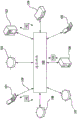
Turning now descriptively to the drawings, wherein like reference numerals refer to like elements throughout the several views, fig. 1 depicts an exemplary communications network 100 in which the following illustrative embodiments may be implemented.
It should be understood that the communications network 100 is a geographically distributed collection of nodes interconnected by communication links and segments for transmitting data between end nodes, such as personal computers, workstations, smart phone devices, tablets, televisions, sensors, and/or other devices (such as automobiles, etc.). Many types of networks are available, ranging in type from Local Area Networks (LANs) to Wide Area Networks (WANs). LANs typically connect the nodes over dedicated private communications links located at the same general physical location, such as a building or campus. WANs, on the other hand, typically connect geographically dispersed nodes over long-distance communication links, such as common carrier telephone lines, optical lightpaths, Synchronous Optical Networks (SONET), Synchronous Digital Hierarchy (SDH) links, or Power Line Communications (PLC), to name a few.
Fig. 1 is a schematic block diagram of an exemplary communication network 100, illustratively including nodes/devices 101-108 (e.g., sensors 102, client computing devices 103, smart phone devices 105, web servers 106, cable test devices 107, switches 108, etc.) interconnected by various communication methods. For example, link 109 may be a wired link or may include a wireless communication medium where certain nodes communicate with other nodes, e.g., based on distance, signal strength, current operating state, location, etc. Further, each device may transmit data packets (or frames) 142 to other devices using predefined network communication protocols as will be understood by those skilled in the art, such as various wired and wireless protocols, etc., where appropriate. In this context, a protocol consists of a set of rules defining how the nodes interact with each other. Those skilled in the art will appreciate that any number of nodes, devices, links, etc. may be used in a computer network, and that the views shown herein are for simplicity. Further, while embodiments are illustrated herein in connection with a general network cloud, the specific embodiments herein are not so limited and may be applied to hardwired networks.
As will be appreciated by one skilled in the art, aspects of the present invention may be embodied as a system, method or computer program product. Accordingly, various aspects of the present invention may take the form of an entirely hardware embodiment, an entirely software embodiment (including firmware, resident software, micro-code, etc.) or an embodiment combining software and hardware aspects that may all be referred to herein as a "circuit," module "or" system. Furthermore, various aspects of the present invention may take the form of a computer program product embodied in one or more computer-readable media having computer-readable program code embodied therein.
Any combination of one or more computer-readable media may be employed. The computer readable medium may be a computer readable signal medium or a computer readable storage medium. A computer readable storage medium may be, for example, but not limited to, an electronic, magnetic, optical, electromagnetic, infrared, or semiconductor system, apparatus, or device, or any suitable combination of the foregoing. More specific examples (a non-exhaustive list) of the computer readable storage medium would include the following: an electrical connection having one or more wires, a portable computer diskette, a hard disk, a Random Access Memory (RAM), a read-only memory (ROM), an erasable programmable read-only memory (EPROM or flash memory), an optical fiber, a portable compact disc read-only memory (CD-ROM), an optical storage device, a magnetic storage device, or any suitable combination of the foregoing. In the context of this document, a computer readable storage medium may be any tangible medium that can contain, or store a program for use by or in connection with an instruction execution system, apparatus, or device.
A computer readable signal medium may include a propagated data signal with computer readable program code embodied therein, for example, in baseband or as part of a carrier wave. Such a propagated signal may take any of a variety of forms, including, but not limited to, electro-magnetic, optical, or any suitable combination thereof. A computer readable signal medium may be any computer readable medium that is not a computer readable storage medium and that can communicate, propagate, or transport a program for use by or in connection with an instruction execution system, apparatus, or device.
Program code embodied on a computer readable medium may be transmitted using any appropriate medium, including but not limited to wireless, wireline, optical fiber cable, RF, etc., or any suitable combination of the foregoing.
Computer program code for carrying out operations for aspects of the present invention may be written in any combination of one or more programming languages, including an object oriented programming language such as Java, Smalltalk, C + + or the like and conventional procedural programming languages, such as the "C" programming language or similar programming languages. The program code may execute entirely on the user's computer, partly on the user's computer, as a stand-alone software package, partly on the user's computer and partly on a remote computer or entirely on the remote computer or server. In the latter scenario, the remote computer may be connected to the user's computer through any type of network, including a Local Area Network (LAN) or a Wide Area Network (WAN), or the connection may be made to an external computer (for example, through the Internet using an Internet service provider).
Aspects of the present invention are described below with reference to flowchart illustrations and/or block diagrams of methods, apparatus (systems) and computer program products according to embodiments of the invention. It will be understood that each block of the flowchart illustrations and/or block diagrams, and combinations of blocks in the flowchart illustrations and/or block diagrams, can be implemented by computer program instructions. These computer program instructions may be provided to a processor of a general purpose computer, special purpose computer, or other programmable data processing apparatus to produce a machine, such that the instructions, which execute via the processor of the computer or other programmable data processing apparatus, create means for implementing the functions/acts specified in the flowchart and/or block diagram block or blocks.
These computer program instructions may also be stored in a computer readable medium that can direct a computer, other programmable data processing apparatus, or other devices to function in a particular manner, such that the instructions stored in the computer readable medium produce an article of manufacture including instructions which implement the function/act specified in the flowchart and/or block diagram block or blocks.
The computer program instructions may also be loaded onto a computer, other programmable data processing apparatus, or other devices to cause a series of operational steps to be performed on the computer, other programmable apparatus or other devices to produce a computer implemented process such that the instructions which execute on the computer or other programmable apparatus provide methods for implementing the functions/acts specified in the flowchart and/or block diagram block or blocks.
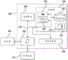
Fig. 2 is a schematic block diagram of an exemplary network computing device 200 (e.g., client computing device 103, server 106, smartphone device 105, cable test device 107) that may be used with one or more embodiments described herein (or components thereof), e.g., as one of the nodes shown in network 100. As described above, in different embodiments, these various devices are configured to communicate with each other in any suitable manner, such as via the communication network 100.
The computing device 200 is operational with numerous other general purpose or special purpose computing system environments or configurations. Examples of well known computing systems, environments, and/or configurations that may be suitable for use with computing device 200 include, but are not limited to, personal computer systems, server computer systems, thin clients, thick clients, hand-held or laptop devices, multiprocessor systems, microprocessor-based systems, set top boxes, programmable consumer electronics, network PCs, minicomputers, distributed data processing environments that include any of the above systems or devices, and the like.
FIG. 2 illustrates a device 200 in the form of a general purpose computing device. The components of device 200 may include, but are not limited to, one or more processors or processing units 216, a system memory 228, and a bus 218 that couples various system components including system memory 228 to processors 216.
The system memory 228 may include computer system readable media in the form of volatile memory, such as Random Access Memory (RAM) 230 and/or cache memory 232. Computing device 200 may also include other removable/non-removable, volatile/nonvolatile computer system storage media. By way of example only, the storage system 234 may read from and write to non-removable, nonvolatile magnetic media (not shown, and commonly referred to as a "hard disk drive"). Although not shown, a magnetic disk drive for reading from and writing to a removable, nonvolatile magnetic disk (e.g., a "floppy disk") and an optical disk drive for reading from and writing to a removable, nonvolatile optical disk such as a CD-ROM, DVD-ROM, or other optical media may be provided. In which case each may be connected to bus 218 by one or more data media interfaces. As will be further depicted and described below, memory 228 may include at least one program product having a set (e.g., at least one) of program modules that are configured to carry out the functions of embodiments of the invention.
A program/utility 240 having a set (at least one) of program modules 215, such as an underwriting module, can be stored in the memory 228 as well as the operating system, one or more application programs, other program modules, and program data by way of example and not limitation. Each of the operating system, one or more application programs, other program modules, and program data or some combination thereof may include an implementation of a networked environment. Program modules 215 generally perform the functions and/or methodologies of embodiments of the present invention as described herein.
The device 200 may also communicate with one or more external devices 214, such as a keyboard, pointing device, display 224, etc.; one or more devices that enable a user to interact with computing device 200; and/or any device (e.g., network card, modem, etc.) that enables computing device 200 to communicate with one or more other computing devices. Such communication may occur via input/output (I/O) interfaces 222. Device 200 may also communicate with one or more networks, such as a Local Area Network (LAN), a general Wide Area Network (WAN), and/or a public network (e.g., the internet), via network adapter 220. As shown, the network adapter 220 communicates with the other components of the computing device 200 via a bus 218. It should be understood that although not shown, other hardware and/or software components may be used in conjunction with device 200. Examples include, but are not limited to: microcode, device drivers, redundant processing units, external disk drive arrays, RAID systems, tape drives, data archival storage systems, and the like.
Fig. 1 and 2 are intended to provide a brief, general description of an illustrative and/or suitable exemplary environment in which embodiments of the invention described below may be implemented. Fig. 1 and 2 are examples of suitable environments and are not intended to suggest any limitation as to the scope of use, or functionality, of embodiments of the invention. The particular environment should not be interpreted as having any dependency or requirement relating to any one or combination of components illustrated in the exemplary operating environment. For example, in some cases, one or more elements of an environment may be considered unnecessary and omitted. In other cases, one or more other elements may be considered necessary and added.
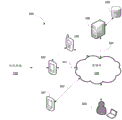
While exemplary communication network 100 (fig. 1) and computing device 200 (fig. 2) are generally shown and discussed above, certain illustrative embodiments of the invention will now be described. Referring now to fig. 3A and 3B, a cloud-based network test system 300 includes a plurality of cable test devices 107 (described below). It should be understood that the cloud-based server/host 106 (also described below) receives test result data from different test devices 107 regarding various functions, including but not limited to: generate statistical data related to the test equipment 107, and authenticate test result data received from the test equipment 107. Additionally, the cloud-based server 106 may be used to analyze the test result data to determine the efficiency of performing the job or by the operator of the test equipment 107.
It should be understood that for ease of illustration, only the use of a single testing device 107 is described, however, it should be appreciated that the cable testing system 300 may involve the use of multiple devices 107 simultaneously. The exemplary test equipment 107 is a portable tool that may include a computer system that serves as a node of a network similar to the communication network 100 shown in FIG. 1. Similarly, server 106 may be a network server including computer systems that serve as nodes of network 100.
The test equipment 107 preferably communicates with the network 100 using a first communication link 302 and the server 106 communicates with the network 100 using a second communication link 304. The first communication link 302 and the second communication link 304 may each comprise a single or multiple wired and/or wireless links. In an embodiment, some of these links use near field communications, such as Radio Frequency Identification (RFID), cellular mobile telecommunications schemes (e.g., 3G, LTE), bluetooth, infrared communications, and so forth. In an embodiment, network 100 includes the Internet. The test equipment 107 may be selectively coupled (using its internal communication components) to the network 100 such that the first communication link 302 may be intermittent, e.g., interrupted and reestablished. During operation, the second communication link 304 may be stable and readily available for communication with the test equipment 107. In other embodiments, the test device 107 communicates indirectly with the cloud-based server 105 via a communication device 106 (such as a mobile phone, tablet computer, or laptop computer).
The testing device 107 and the cloud-based server 106 may each be configured similar to the network computing device 200 shown in fig. 2, such as being configured to include a processing unit 216, a network adapter 220, an I/O interface 222, and a memory 228.
It should be understood that the network test system 300 may encompass a variety of different types of cable test equipment 107. Examples include, but are not limited to, a flow Fluke Network®The instrument comprises the following steps: optifiber® Pro OTDR;CertiFiber®Pro light loss assayTester and DSX-5000 CableAnalyzerTM. It should also be understood that the illustrative embodiments of the present disclosure encompass testing of network cables, including diagnostics, verification, authentication, and certification. With respect to authentication testing, as a non-limiting example, sourced from Fluke Network®Versiv ofTMProducts may be used to facilitate such cable authentication.
The test equipment 107 may allow multiple applications to operate simultaneously. It should be understood that the test equipment 107 may include hardware/servers embedded in an operating system (e.g., Linux). As will be described further below, using a combination of operating system features, the testing device 107 may be configured to receive firmware updates and test configurations over a network connection (preferably via the Internet 100). As will also be further explained below, the test configuration is preferably a software package that is sent from the cloud-based server device 106 (via the network 100) to the test device 107 to enable/configure the test device 107 to execute a predetermined test routine on the network 350 to be tested by the test device 107.
In operation, the testing equipment 107 may perform cable testing, for example, to diagnose, verify, certify, or qualify copper or fiber optic cables. The cables to be tested may include low voltage CAT3, CAT5, CAT5E, CAT6, UTP, STP, SSTP, and/or FTP data cables, standard voltage wires, and/or connectors (e.g., connecting devices) connecting two or more cables forming part of a network within a premise connection foundation (e.g., a residence, an office, a school, etc.). In an exemplary test procedure, one or more ports of the I/O interface 222 of the test equipment are coupled to at least one patch panel port of a patch panel in the data room via a patch cable for exchanging test signals and responses to the test signals. The test procedure may include, for example, a cable integrity test or a network connectivity test associated with one or more networking devices (e.g., routers, switches, end devices, etc.).
As shown in FIG. 3B, the test equipment 107 is typically a portable device that may also include test equipment 312, environmental sensors 314, and/or a location detector 316. The test equipment 312 includes one or more sensors for measuring electrical characteristics of the signal source or power source. The environmental sensors 314 include one or more sensors for measuring a characteristic of a physical entity (such as temperature, humidity, applied force, etc.). Environmental sensor 314 may also detect electromagnetic interference (e.g., radio frequency interference), such as to determine proximity to a device emitting electromagnetic energy. The test equipment 312 and the environmental sensors 314 may include analog-to-digital (A/D) converters that convert the output signals to digital data. The outputs from the test equipment 312 and the environmental sensors 314 may be time stamped.
The position detector 316 senses the position of the test equipment 107. The location detector 316 may include a Global Positioning System (GPS) sensor. In an embodiment, the location detector 316 may include a sensor that detects a characteristic (such as an optical code or RFID code) associated with a fixed device whose location is known.
Additionally, in an embodiment, the location detector 316 may include a device located external to the test device 107 and/or contained within the cloud-based server 106. In one embodiment, the location detector 316 may be associated with a fixed device whose location is known. A location detector 316 associated with the stationary device may sense the presence of the test device 107 (e.g., using optical sensing, RFID, bluetooth, etc.). In another embodiment, a position detector 316 included in the test device 107 may detect the position of the fixture and use the position of the fixture. In either case, the location of the fixture can be used to determine the location of the testing device 107. Further, in an embodiment, the location detector 316 may include logic to infer the location of the test device 107 from network signals, such as IP addresses, RFID, WIFI, and bluetooth MAC addresses, and/or GSM/CDMA cell IDs associated with the test device 107. The location detector 316 outputs time-stamped location data indicative of the location of the test device 107. The location data may include geographic location data and/or the location of the testing device 107 inside the building (such as relative to a floor map).
The test equipment 312, environmental sensors 314, and location detector 316 may include hardware modules and software modules (e.g., program modules 215 stored by the memory 228 of the server 106).
The I/O interface 222 of the test equipment may include one or more cable ports (e.g., ethernet ports, data cable receptacles such as RJ 45 receptacles, wire clamps, optical ports, etc.) that interface with a cable, such as a patch cord. The test signals and responses may be transmitted and received via the cable port.
The processing unit 216 of the test device is configured to select test signals to be transmitted via the cable port (e.g., ping) in accordance with test configuration instructions typically stored in the device memory 228. The processing unit 216 may also process signals received in response to transmitting test signals via the port. The processing unit 216 may process outputs received from the test equipment 312 and environmental sensors 314, perform one or more circuit and/or network connectivity diagnostic tests, and generate corresponding test result data according to particular test configuration instructions. The test result data may include metadata and data that provides information about the test procedure and test results.
For example, the test result data may indicate which type of entity (e.g., voltage, current, time (e.g., time interval from ping transmission to ping reception), IP address, bit rate, packet capture rate, etc.) to read or measure and the value read or measured. The measured value may be an electrical characteristic (e.g., voltage or current), time, IP address, bit rate, packet capture rate, or other measure indicative of network device performance and/or network connectivity performance, etc., detected on the cable. Under instruction from a particular test configuration, processing unit 216 may generate test result data using utilities such as network scan, network mapping, DNS resolution, DHCP, PING, TraceRoute, IPerf IPv4, and IPv 6.
Examples of information that may be further provided by the test result data and associated metadata include: information about the time at which the test procedure started and completed; identification of one or more operators operating the test equipment 107; identification of the test equipment 107; identification of patch cords coupled to the test equipment 107; identifying a tested cable; location data indicating a geographic location at the time of the testing procedure; environmental conditions at the time of the test procedure; identification of the test procedure being executed and/or the job to which the test procedure belongs.
The job may be, for example, an installation job in which a network or a portion of a network is installed at a particular location. In another example, the job may be a diagnostic job to identify and correct a problem. In another example, and not limited to the listed examples, the job may be a maintenance job to determine or measure network performance.
The identification of the test equipment 107, the cable under test, and/or the patch cords used may be used to determine additional information, such as the make, model, manufacturer, owner, etc. of the test equipment 107. The identification of the test procedure and associated job may be used to determine additional information, such as a customer for which the test procedure or associated job is to be executed as a service; which customer uses the tested cable for data communication, the associated monetary value (cost or settleable value) of the testing process; and/or geographic location, time, cable, patch cord, operator, duration, etc., the additional information being specified in connection with a test procedure or job.
During a test procedure pursuant to executing a test configuration as received from cloud-based server 106 (as further described below), test equipment 107 may generate one or more test signals, transmit the test signals for testing the cable, receive responsive test signals, process the responsive test signals, and transmit the results to cloud-based server 106 for analysis thereof. Processing the response test signal may include verifying that the cable received and transmitted data as expected (e.g., whether the cable was properly connected, whether component wires of the cable have been properly terminated without crossing, whether all wires in the cable are transmitting data, etc.). When data is obtained from a test (in accordance with the received test configuration settings of the execution received from the cloud-based server 106), the data may be stored in the test device 107 and/or transmitted to the cloud-based server 106. Additionally, the data may be aggregated for comparison with data from other test devices 107 or cloud-based servers 106.
The cloud-based server 106 receives test result data from a plurality of test devices 107. It should be appreciated that cloud-based server 106 may implement a Fluke Network-sourced implementation®LinkWareTMLive products to store and manage test result data received from the remote test equipment 107 and to transmit test configurations to the test equipment 107, as described further below.
Cloud-based server 106 preferably includes a statistics module 322, an efficiency module 324, an authentication module 326, and an environment correlation module 328, each of which may include a software module (e.g., program modules 215 stored by memory 228 of server 304). The cloud-based server 106 includes or is coupled to a database 330 that stores information for a plurality of test devices 107 that may be coupled to the cloud-based server 106 via the network 100. The information stored by database 330 may include, for example, cable test result data, operator data, environmental condition data, statistical data, and/or reporting data.
According to the illustrated embodiment, and as discussed further below with respect to the flowchart of fig. 4, a plurality of test configuration settings 332 are stored in a database 330 associated with the cloud-based server 106, the test configurations 332 being remotely selectable by a user of the test device 107 or a remote user 103 of the test device 107 in order to "download" from the cloud-based server 106 to the remotely located test device 107 for execution by the test device 107, as described herein. Once downloaded, the user of the test device 107 selects a configuration, causing the test device to apply the downloaded and selected test configuration. Thus, the user 103, who is remote from the testing device 107, is enabled to configure the test parameters of the measuring device 107 without the need for the presence of the device 107. It should be understood that cloud service 106 may potentially configure many different parameters, including but not limited to: 1) types of media including, but not limited to, optical fiber and copper; 2) a cable type within the selected media type; 3) assigned test types including, but not limited to, copper, OTDR, loss/length, and fiber detection; 4) identification of cable ends for testing of optional tests, such as OTDR; 5) setting parameters and controlling the measurement of the test type; 6) the assignment of cables associated with each test type; 7) a marking scheme associated with each cable; and 8) the type of data saved in the measurement result file.
The remote user 103 may access the cloud-based services provided by the cloud-based server 304 via a user computing device (e.g., the node smartphone device 105, the client computing device 103, or the test device 302) to request and/or receive information output by the cloud-based server 304. In an exemplary embodiment, access to the cloud-based service may be provided by web browser software residing on a user computing device running an application (e.g., a Java applet or other application), which may include an application programming interface ("API") connected to a more complex application running on a remote server.
In an exemplary embodiment, a user may log into the cloud-based service using the computer 103 (e.g., through web browser software resident on the computer 103 in communication with the cloud-based server device 106) via web browser software to access the cloud-based application of one or more test devices 107. After logging into the cloud-based application on the server 106, the user may create, edit, save, and delete the aforementioned cable test configurations in the cloud-based server device 106, and may establish (set) or change/edit various options (such as user preferences and/or system settings), and/or may receive or download software (e.g., an operating system or other software) or software updates, various data files or media files, user preferences, and/or system settings, and other information previously stored on the cloud-based server device 106.
According to the illustrated embodiment, a cloud-based application implemented on a cloud-based server device 106 may provide various cable test configurations that facilitate cable testing by one or more test devices 107. Thus, illustrated is a cloud-based computer server 106 for performing cable diagnostics according to test results received from at least one test device 107 configured to perform cable tests in accordance with a cable test configuration with respect to a network 350 to be tested, as specified by the remotely located server 106.
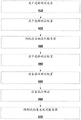
Referring now to fig. 4, a flow diagram is shown illustrating an implementation of various exemplary embodiments with respect to selecting test device configuration instructions from cloud-based server device 106 and transmitting the test device configuration instructions to one or more test devices 107 via network 100. It is noted that the order of operations shown in fig. 4 is not required, and thus various operations may in principle be performed out of the order shown. Certain operations may also be skipped, different operations may be added or substituted, or selected operations or groups of operations may be performed in separate applications following the embodiments described herein.
Beginning at operation 410, a user (who may be remote from the test device (e.g., user 103), or who may be a user of the test device 107) preferably logs in to a program implemented on the cloud-based server device 106 (as described above) to first select one or more test devices 107 designated to receive test configuration instructions. Next, at step 420, the user preferably selects one or more test configuration instructions to be sent to the selected device 107 (step 410). In the event that the test device 107 has not been coupled for data communication with the cloud-based server device 106 (as described above), the test device 107 is coupled to the cloud-based server device 106 for data communication therewith, step 430.
Once the designated test device 107 (step 410) is coupled to the cloud-based server device 106 (step 430), the selected test configuration instructions (step 420) are sent, preferably as data packets, from the cloud-based server device 106 to the designated test device 107, step 440. Thereafter, the test equipment 107 preferably stores the received test configuration instruction packet in the device memory 228 for later selection by a user of the test equipment 107, step 450. Once selected, the processing unit 216 of the test equipment 107 causes the test equipment 107 to preferably perform cable network testing (as described above) based on the specified equipment test parameters and setup configurations according to the selected test configuration instructions, step 460. After the test device 107 performs the prescribed test (step 450), the test device 107 preferably causes the test results to be transmitted to the cloud-based server device 106 (via the network 100, as described above), step 470.
Thus, the above-described embodiments enable a user to configure test parameters of the measurement/test device 107 without the need for the device 107 to be present.
It is to be understood that the above-described arrangements are only illustrative of the application of the principles of the exemplary embodiments. Numerous modifications and alternative arrangements may be devised by those skilled in the art without departing from the scope of the illustrated embodiments, and the appended claims are intended to cover such modifications and arrangements.
Claims (13)
1. A method for testing a cable network, comprising:
storing, at a cloud host device, a plurality of test device configuration instructions for configuring a plurality of cable network test devices to perform different cable network test procedures;
receiving, at the cloud host device and from a first computing device, each of:
a selection of a cable network test device from the plurality of cable network test devices, wherein the selected cable network test device is separate from the first computing device, an
A first selection of test device configuration instructions from the plurality of test device configuration instructions to provide to the selected cable network test device;
receiving, at the selected cable network test device and from the cloud host device, one or more data packets containing first selected test device configuration instructions;
receiving, at the selected cable network test device and from a user of the selected cable network test device, a second selection of one or more test device configuration instructions from the first selected test device configuration instructions;
configuring the selected cable network test device to perform one or more cable network test procedures based on the second selected test device configuration instructions; and
executing, by the selected cable network test device, the one or more cable network test procedures according to the second selected test device configuration instructions.
2. The method of claim 1, wherein the one or more data packets are received wirelessly by the selected cable network test device.
3. The method of claim 2, wherein the selected cable network test device is coupled to the cloud host device via a Wide Area Network (WAN).
4. The method of claim 1, wherein the selected cable network test device is coupled to a separate communication device, and wherein the communication device is wirelessly coupled to the cloud host device via a Wide Area Network (WAN).
5. The method of claim 1, wherein the plurality of test device configuration instructions specify at least one of: the type of cable media to be tested; the type of cable to be tested; and the assigned test type.
6. The method of claim 1, wherein the plurality of test device configuration instructions specify at least one of: a specified cable end to be tested; setting parameters for test measurements of the control cable; the assignment of cables associated with each test type; a marking scheme associated with each cable to be tested; and a type of test result data to be captured in the cable network test device.
7. A system for testing a cable network, comprising:
at least one cable test device configured to perform cable testing in accordance with a cable test configuration;
a cloud host device configured to couple to the at least one cable test device to transmit data therewith, the cloud host device comprising:
a database configured to store a plurality of cable test configurations, each cable test configuration capable of configuring a cable test device to perform a cable test procedure according to predefined instructions; and
a processor configured to:
receiving, from a first computing device separate from the at least one cable test device, a selection of a cable test device from the at least one cable test device and a first selection of a cable test configuration from the plurality of cable test configurations in the database; and
transmitting a first selected cable test configuration to the selected cable test equipment; and is
Wherein the at least one cable test device includes a selected cable test device comprising a processor configured to:
receiving one or more data packets containing a first selected cable test configuration from the cloud host device;
receiving, from a user of the selected cable test device, a second selection of one or more cable test configurations from the first selected cable test configuration; and
one or more cable test procedures are performed according to the second selected cable test configuration.
8. The system of claim 7, wherein the cable test includes performing at least one of a cable certification, a certification, and a verification of the cable.
9. The system of claim 7, wherein the cloud host device is wirelessly coupled to the at least one cable test device.
10. The system of claim 9, wherein the cable test device is coupled to the cloud host device via a Wide Area Network (WAN).
11. The system of claim 7, wherein the selected cable test device is coupled to a separate communication device, and wherein the communication device is wirelessly coupled to the cloud host device via a Wide Area Network (WAN).
12. The system of claim 7, wherein the plurality of cable test configurations specify at least one of: the type of cable media to be tested; the type of cable to be tested; and the assigned test type.
13. The system of claim 7, wherein the plurality of cable test configurations specify at least one of: a specified cable end to be tested; setting parameters for test measurements of the control cable; the assignment of cables associated with each test type; a marking scheme associated with each cable to be tested; and the type of test result data to be captured in the test device.
Applications Claiming Priority (3)
| Application Number | Priority Date | Filing Date | Title |
|---|---|---|---|
| US14/884,131 US10367713B2 (en) | 2015-10-15 | 2015-10-15 | Cloud based system and method for managing testing configurations for cable test devices |
| US14/884131 | 2015-10-15 | ||
| PCT/US2016/057206 WO2017066693A1 (en) | 2015-10-15 | 2016-10-14 | Cloud based system and method for managing testing configurations for cable test devices |
Publications (2)
| Publication Number | Publication Date |
|---|---|
| CN108141385A CN108141385A (en) | 2018-06-08 |
| CN108141385B true CN108141385B (en) | 2021-10-29 |
Family
ID=57219012
Family Applications (1)
| Application Number | Title | Priority Date | Filing Date |
|---|---|---|---|
| CN201680060100.0A Active CN108141385B (en) | 2015-10-15 | 2016-10-14 | Cloud-based system and method for managing test configuration of cable test equipment |
Country Status (6)
| Country | Link |
|---|---|
| US (1) | US10367713B2 (en) |
| EP (1) | EP3363156B1 (en) |
| JP (1) | JP6876038B2 (en) |
| CN (1) | CN108141385B (en) |
| AU (1) | AU2016337397B2 (en) |
| WO (1) | WO2017066693A1 (en) |
Families Citing this family (17)
| Publication number | Priority date | Publication date | Assignee | Title |
|---|---|---|---|---|
| CN103973362A (en) * | 2013-02-06 | 2014-08-06 | 中兴通讯股份有限公司 | Method and device for setting OTDR (optical time domain reflectometer) test parameter set |
| EP3119093B1 (en) * | 2014-03-10 | 2019-10-30 | SK TechX Co., Ltd. | Method for testing cloud streaming server, and apparatus and system therefor |
| WO2016041866A1 (en) * | 2014-09-17 | 2016-03-24 | British Telecommunications Public Limited Company | Communication set up process |
| US10602082B2 (en) | 2014-09-17 | 2020-03-24 | Fluke Corporation | Triggered operation and/or recording of test and measurement or imaging tools |
| US10271020B2 (en) * | 2014-10-24 | 2019-04-23 | Fluke Corporation | Imaging system employing fixed, modular mobile, and portable infrared cameras with ability to receive, communicate, and display data and images with proximity detection |
| US20170078544A1 (en) | 2015-09-16 | 2017-03-16 | Fluke Corporation | Electrical isolation for a camera in a test and measurement tool |
| WO2017070629A1 (en) | 2015-10-23 | 2017-04-27 | Fluke Corporation | Imaging tool for vibration and/or misalignment analysis |
| EP3280075A1 (en) | 2016-08-03 | 2018-02-07 | Rohde & Schwarz GmbH & Co. KG | Measurement system and a method |
| US10701571B2 (en) | 2016-08-12 | 2020-06-30 | W2Bi, Inc. | Automated validation and calibration portable test systems and methods |
| US10681570B2 (en) | 2016-08-12 | 2020-06-09 | W2Bi, Inc. | Automated configurable portable test systems and methods |
| US10158552B2 (en) * | 2016-08-12 | 2018-12-18 | W2Bi, Inc. | Device profile-driven automation for cell-based test systems |
| US9955371B1 (en) * | 2017-01-04 | 2018-04-24 | Rohde & Schwarz Gmbh & Co. Kg | Method for testing a device under test, electronic device, and measurement unit |
| CA3034830A1 (en) | 2018-06-14 | 2019-12-14 | Exfo Inc. | Validation of test results in network testing |
| US11200319B2 (en) * | 2019-04-04 | 2021-12-14 | Cisco Technology, Inc. | Cloud enabling of legacy trusted networking devices for zero touch provisioning and enterprise as a service |
| CN110162880B (en) * | 2019-05-22 | 2023-05-16 | 上海电力设计院有限公司 | Optical cable laying method, device, equipment and medium |
| CN112311601A (en) * | 2020-10-30 | 2021-02-02 | 中电凯杰科技有限公司 | Motor driver debugging system and method |
| CN115801649B (en) * | 2022-11-01 | 2024-05-28 | 一汽解放汽车有限公司 | Wire harness testing system and method |
Citations (2)
| Publication number | Priority date | Publication date | Assignee | Title |
|---|---|---|---|---|
| CN104506595A (en) * | 2014-12-12 | 2015-04-08 | 国家电网公司 | Portable communication device for detecting electric transmission and transformation equipment and data transmission method of portable communication device |
| CN104980312A (en) * | 2014-04-04 | 2015-10-14 | 维珍奈尼思(格伦罗西斯)有限公司 | A Portable Testing Apparatus And Method |
Family Cites Families (84)
| Publication number | Priority date | Publication date | Assignee | Title |
|---|---|---|---|---|
| US5311516A (en) | 1992-05-29 | 1994-05-10 | Motorola, Inc. | Paging system using message fragmentation to redistribute traffic |
| EP0789462B1 (en) * | 1996-02-12 | 2004-09-29 | Fluke Corporation | Method and apparatus for processing time domain cross-talk information |
| US6041355A (en) | 1996-12-27 | 2000-03-21 | Intel Corporation | Method for transferring data between a network of computers dynamically based on tag information |
| US5731706A (en) * | 1997-02-18 | 1998-03-24 | Koeman; Henriecus | Method for efficient calculation of power sum cross-talk loss |
| CA2369122C (en) | 1999-06-04 | 2008-01-22 | Rex J. Crookshanks | Building construction bid and contract management system, internet-based method and computer program therefor |
| US6823479B1 (en) | 2000-02-14 | 2004-11-23 | Teradyne, Inc. | Network fault analysis tool |
| US6496014B1 (en) | 2000-07-18 | 2002-12-17 | Agilent Technologies, Inc. | Cable tester error compensation method and apparatus |
| US20060074727A1 (en) | 2000-09-07 | 2006-04-06 | Briere Daniel D | Method and apparatus for collection and dissemination of information over a computer network |
| US7657872B2 (en) | 2000-10-23 | 2010-02-02 | Nintendo Of America Inc. | Product testing and bug tracking system |
| US7010730B1 (en) | 2000-11-01 | 2006-03-07 | Sunrise Telecom Incorporated | System and method for testing the upstream channel of a cable network |
| US6883118B2 (en) | 2001-01-24 | 2005-04-19 | Microsoft Corporation | Consumer network diagnostic agent |
| US7181017B1 (en) | 2001-03-23 | 2007-02-20 | David Felsher | System and method for secure three-party communications |
| US20030134599A1 (en) | 2001-08-08 | 2003-07-17 | Pangrac David M. | Field technician assistant |
| US6757790B2 (en) | 2002-02-19 | 2004-06-29 | Emc Corporation | Distributed, scalable data storage facility with cache memory |
| WO2003087856A1 (en) | 2002-04-17 | 2003-10-23 | Advantest Corporation | Network analyzer, network analyzing method, automatic corrector, correcting method, program, and recording medium |
| US20040015744A1 (en) | 2002-07-22 | 2004-01-22 | Finisar Corporation | Scalable multithreaded network testing tool |
| US6847213B2 (en) | 2002-12-12 | 2005-01-25 | Ideal Industries, Inc. | Hand-held tester and method for local area network cabling |
| US7479776B2 (en) | 2002-12-12 | 2009-01-20 | Ideal Industries, Inc. | Hand-held tester and method for local area network cabling |
| US7024548B1 (en) | 2003-03-10 | 2006-04-04 | Cisco Technology, Inc. | Methods and apparatus for auditing and tracking changes to an existing configuration of a computerized device |
| US7457866B1 (en) | 2003-03-24 | 2008-11-25 | Netapp, Inc. | Method and apparatus for diagnosing connectivity problems from a network management station |
| US6832168B2 (en) | 2003-04-04 | 2004-12-14 | Hewlett-Packard Development Company, L.P. | Method and system for verifying network device power cabling configuration |
| JP2005172728A (en) | 2003-12-15 | 2005-06-30 | Agilent Technol Inc | Calibration verification method in network analyzer, network analyzer provided with functional means for implementing same method, and program for implementing same method |
| US7860115B1 (en) | 2003-12-18 | 2010-12-28 | Cisco Technology, Inc. | Withdrawing multiple advertised routes based on a single tag which may be of particular use in border gateway protocol |
| US7623784B1 (en) | 2004-05-04 | 2009-11-24 | Sprint Communications Company L.P. | Network connection verification in optical communication networks |
| US9189756B2 (en) | 2004-09-21 | 2015-11-17 | International Business Machines Corporation | Case management system and method for collaborative project teaming |
| US7502850B2 (en) | 2005-01-06 | 2009-03-10 | International Business Machines Corporation | Verifying resource functionality before use by a grid job submitted to a grid environment |
| US8488472B2 (en) | 2006-02-22 | 2013-07-16 | Hewlett-Packard Development Company, L.P. | Automated cable identification and verification system |
| US8312523B2 (en) | 2006-03-31 | 2012-11-13 | Amazon Technologies, Inc. | Enhanced security for electronic communications |
| US7979532B2 (en) | 2006-09-15 | 2011-07-12 | Oracle America, Inc. | Systems and methods for using an access point for testing multiple devices and using several consoles |
| US20080208806A1 (en) | 2007-02-28 | 2008-08-28 | Microsoft Corporation | Techniques for a web services data access layer |
| US20080275714A1 (en) | 2007-05-01 | 2008-11-06 | David Frederick Martinez | Computerized requirement management system |
| US20080300945A1 (en) | 2007-05-31 | 2008-12-04 | Michel Shane Simpson | Techniques for sharing resources across multiple independent project lifecycles |
| US7720940B1 (en) | 2007-09-28 | 2010-05-18 | World Wide Packets, Inc. | Managing a network element using a template configuration |
| JP2009212616A (en) * | 2008-02-29 | 2009-09-17 | Ad-Sol Nissin Corp | Device for evaluating transmission path environment in power line communication network |
| US8174996B2 (en) | 2008-06-24 | 2012-05-08 | Verizon Patent And Licensing Inc. | Adaptive test system for network function and performance evaluation |
| US8259907B2 (en) | 2008-12-12 | 2012-09-04 | Centurylink Intellectual Property Llc | System and method for assisting field communications technicians in repairing communications lines |
| US8521092B2 (en) | 2009-05-27 | 2013-08-27 | Echo Ridge Llc | Wireless transceiver test bed system and method |
| EP2441053B1 (en) * | 2009-06-10 | 2018-08-08 | Hexagon Technology Center GmbH | Ontological filtering using spatial boundary of 3d objects |
| US20110084132A1 (en) | 2009-10-08 | 2011-04-14 | At&T Intellectual Property I, L.P. | Devices, Systems and Methods for Secure Remote Medical Diagnostics |
| US8625441B2 (en) | 2009-10-29 | 2014-01-07 | Fluke Corporation | System and method for measuring and displaying presence of wireless local area network devices |
| US9225539B2 (en) | 2010-01-15 | 2015-12-29 | Hewlett Packard Enterprise Development Lp | Storing data relating to cables |
| US8355926B1 (en) | 2010-02-08 | 2013-01-15 | Accenture Global Services Limited | Health and life sciences medicaid high performance capability assessment |
| US20130041613A1 (en) * | 2011-08-10 | 2013-02-14 | International Business Machines Corporation | Generating a test suite for broad coverage |
| US8819490B2 (en) | 2011-12-30 | 2014-08-26 | Microsoft Corporation | Test execution spanning cloud and local devices |
| US9069719B2 (en) | 2012-02-11 | 2015-06-30 | Samsung Electronics Co., Ltd. | Method and system for providing a smart memory architecture |
| US9077646B2 (en) | 2012-02-13 | 2015-07-07 | Fluke Corporation | Method and apparatus for testing and displaying test results |
| US9251360B2 (en) | 2012-04-27 | 2016-02-02 | Intralinks, Inc. | Computerized method and system for managing secure mobile device content viewing in a networked secure collaborative exchange environment |
| US9253176B2 (en) | 2012-04-27 | 2016-02-02 | Intralinks, Inc. | Computerized method and system for managing secure content sharing in a networked secure collaborative exchange environment |
| US20130305091A1 (en) | 2012-05-09 | 2013-11-14 | Ixia | Drag and drop network topology editor for generating network test configurations |
| US8813228B2 (en) | 2012-06-29 | 2014-08-19 | Deloitte Development Llc | Collective threat intelligence gathering system |
| US9291695B2 (en) | 2012-08-06 | 2016-03-22 | Fluke Corporation | Real-time RF signal visualization device |
| US9397922B1 (en) | 2013-02-28 | 2016-07-19 | EarthLink, LLC | Automated network testing platform |
| US9369447B2 (en) | 2013-03-12 | 2016-06-14 | Maxim Integrated Products, Inc. | System and method to securely transfer data |
| US9112718B2 (en) * | 2013-03-15 | 2015-08-18 | Vtrum Group Llc | Broadband diagnostics system |
| US8935765B2 (en) | 2013-03-15 | 2015-01-13 | Fluke Corporation | Method to enable mobile devices to rendezvous in a communication network |
| WO2014145153A2 (en) | 2013-03-15 | 2014-09-18 | Neeley John | Automatic recording and graphing of measurement data |
| US10284632B2 (en) | 2013-03-29 | 2019-05-07 | WOW Insites LLC | Electronic testing device |
| WO2014161003A1 (en) | 2013-03-29 | 2014-10-02 | WOW Insites LLC | Electronic testing device |
| US20140337674A1 (en) | 2013-05-10 | 2014-11-13 | Nec Laboratories America, Inc. | Network Testing |
| US9749039B1 (en) | 2013-06-10 | 2017-08-29 | Amazon Technologies, Inc. | Portable connection diagnostic device |
| US9350550B2 (en) | 2013-09-10 | 2016-05-24 | M2M And Iot Technologies, Llc | Power management and security for wireless modules in “machine-to-machine” communications |
| CN103560810B (en) * | 2013-11-15 | 2016-04-06 | 哈尔滨工业大学 | Based on the wireline test controller of CAN communication |
| AU2014363926A1 (en) | 2013-12-11 | 2015-08-27 | Intralinks, Inc. | Customizable secure data exchange environment |
| US8910294B1 (en) | 2013-12-18 | 2014-12-09 | State Farm Mutual Automobile Insurance Company | System and method for application failure testing in a cloud computing environment |
| US10305893B2 (en) * | 2013-12-27 | 2019-05-28 | Trapezoid, Inc. | System and method for hardware-based trust control management |
| US9614745B2 (en) | 2014-01-09 | 2017-04-04 | Citrix Systems, Inc. | Systems and methods for cloud-based probing and diagnostics |
| MX2016011262A (en) | 2014-03-04 | 2017-01-23 | Black Diamond Video Inc | Apparatuses, methods, and systems for troubleshooting multimedia network communication systems. |
| US9140745B1 (en) | 2014-03-05 | 2015-09-22 | Unigen Corporation | System and method for cloud testing and remote monitoring of integrated circuit devices |
| US9665473B2 (en) | 2014-03-25 | 2017-05-30 | Accenture Global Services Limited | Smart tester application for testing other applications |
| US10094866B2 (en) | 2014-04-01 | 2018-10-09 | The United States Of America, As Represented By The Secretary Of The Navy | Portable multi-function cable tester |
| WO2015164521A1 (en) | 2014-04-23 | 2015-10-29 | Intralinks, Inc. | Systems and methods of secure data exchange |
| US9467385B2 (en) | 2014-05-29 | 2016-10-11 | Anue Systems, Inc. | Cloud-based network tool optimizers for server cloud networks |
| US10250483B2 (en) | 2014-06-25 | 2019-04-02 | Ca, Inc. | System and method thereof for dynamically testing networked target systems through simulation by a mobile device |
| US9733627B2 (en) | 2014-08-13 | 2017-08-15 | Honeywell International Inc. | Cloud computing system and method for advanced process control |
| US20160072693A1 (en) | 2014-09-09 | 2016-03-10 | Avaya Inc. | Client-server communication evaluation and diagnostic tool |
| US10401411B2 (en) | 2014-09-29 | 2019-09-03 | Ecoatm, Llc | Maintaining sets of cable components used for wired analysis, charging, or other interaction with portable electronic devices |
| US9568530B2 (en) | 2014-10-29 | 2017-02-14 | Intel Corporation | Active cable testing |
| US20160301575A1 (en) | 2015-04-07 | 2016-10-13 | Quanta Computer Inc. | Set up and verification of cabling connections in a network |
| US20160330221A1 (en) | 2015-05-07 | 2016-11-10 | Cyber-Ark Software Ltd. | Systems and Methods for Detecting and Reacting to Malicious Activity in Computer Networks |
| IN2015CH05184A (en) | 2015-09-28 | 2015-10-16 | Wipro Ltd | |
| US9730004B2 (en) | 2015-09-30 | 2017-08-08 | Sartorius Stedim Biotech Gmbh | System, network and method for securing contactless communications |
| US10361945B2 (en) * | 2015-10-08 | 2019-07-23 | Fluke Corporation | System and method to reconcile cabling test results with cabling test configurations |
| US9900325B2 (en) | 2015-10-09 | 2018-02-20 | Microsoft Technology Licensing, Llc | Passive encryption of organization data |
| US9959181B2 (en) | 2015-11-13 | 2018-05-01 | Fluke Corporation | System and method for cloud-service asset management for portable computer test tools |
-
2015
- 2015-10-15 US US14/884,131 patent/US10367713B2/en active Active
-
2016
- 2016-10-14 JP JP2018518958A patent/JP6876038B2/en active Active
- 2016-10-14 EP EP16788871.8A patent/EP3363156B1/en active Active
- 2016-10-14 AU AU2016337397A patent/AU2016337397B2/en active Active
- 2016-10-14 CN CN201680060100.0A patent/CN108141385B/en active Active
- 2016-10-14 WO PCT/US2016/057206 patent/WO2017066693A1/en active Application Filing
Patent Citations (2)
| Publication number | Priority date | Publication date | Assignee | Title |
|---|---|---|---|---|
| CN104980312A (en) * | 2014-04-04 | 2015-10-14 | 维珍奈尼思(格伦罗西斯)有限公司 | A Portable Testing Apparatus And Method |
| CN104506595A (en) * | 2014-12-12 | 2015-04-08 | 国家电网公司 | Portable communication device for detecting electric transmission and transformation equipment and data transmission method of portable communication device |
Also Published As
| Publication number | Publication date |
|---|---|
| JP6876038B2 (en) | 2021-05-26 |
| JP2019501553A (en) | 2019-01-17 |
| AU2016337397A1 (en) | 2018-04-26 |
| AU2016337397B2 (en) | 2020-03-12 |
| WO2017066693A1 (en) | 2017-04-20 |
| EP3363156A1 (en) | 2018-08-22 |
| EP3363156B1 (en) | 2021-05-26 |
| US10367713B2 (en) | 2019-07-30 |
| CN108141385A (en) | 2018-06-08 |
| US20170111258A1 (en) | 2017-04-20 |
Similar Documents
| Publication | Publication Date | Title |
|---|---|---|
| CN108141385B (en) | Cloud-based system and method for managing test configuration of cable test equipment | |
| CN108141390B (en) | Cloud-based system and method for managing messages regarding cable test equipment operation | |
| AU2016256717C1 (en) | System and method for applying aggregated cable test result data | |
| CN106789401A (en) | The performance test methods and system of a kind of double-frequency wireless router | |
| CN108141381B (en) | System and method to coordinate cable test results with cable test configuration | |
| CN104023353A (en) | Router performance test method and test system | |
| CN103441894A (en) | Method and system for L2TP concurrent connection performance test | |
| CN109167707A (en) | A kind of shunting device test macro, method, apparatus, server and storage medium | |
| JP6068540B2 (en) | Information providing apparatus, communication apparatus, information providing method, and program | |
| CN105548679B (en) | Communication terminal power detection system and detection method | |
| CN104506391A (en) | Method and device for testing private Ethernet line |
Legal Events
| Date | Code | Title | Description |
|---|---|---|---|
| PB01 | Publication | ||
| PB01 | Publication | ||
| SE01 | Entry into force of request for substantive examination | ||
| SE01 | Entry into force of request for substantive examination | ||
| GR01 | Patent grant | ||
| GR01 | Patent grant |