CN108137125B - bicycle transmission - Google Patents
bicycle transmission Download PDFInfo
- Publication number
- CN108137125B CN108137125B CN201680060965.7A CN201680060965A CN108137125B CN 108137125 B CN108137125 B CN 108137125B CN 201680060965 A CN201680060965 A CN 201680060965A CN 108137125 B CN108137125 B CN 108137125B
- Authority
- CN
- China
- Prior art keywords
- ring gear
- bicycle transmission
- connecting core
- bicycle
- core
- Prior art date
- Legal status (The legal status is an assumption and is not a legal conclusion. Google has not performed a legal analysis and makes no representation as to the accuracy of the status listed.)
- Active
Links
Images


Classifications
-
- B—PERFORMING OPERATIONS; TRANSPORTING
- B62—LAND VEHICLES FOR TRAVELLING OTHERWISE THAN ON RAILS
- B62M—RIDER PROPULSION OF WHEELED VEHICLES OR SLEDGES; POWERED PROPULSION OF SLEDGES OR SINGLE-TRACK CYCLES; TRANSMISSIONS SPECIALLY ADAPTED FOR SUCH VEHICLES
- B62M9/00—Transmissions characterised by use of an endless chain, belt, or the like
- B62M9/04—Transmissions characterised by use of an endless chain, belt, or the like of changeable ratio
- B62M9/06—Transmissions characterised by use of an endless chain, belt, or the like of changeable ratio using a single chain, belt, or the like
- B62M9/10—Transmissions characterised by use of an endless chain, belt, or the like of changeable ratio using a single chain, belt, or the like involving different-sized wheels, e.g. rear sprocket chain wheels selectively engaged by the chain, belt, or the like
- B62M9/105—Transmissions characterised by use of an endless chain, belt, or the like of changeable ratio using a single chain, belt, or the like involving different-sized wheels, e.g. rear sprocket chain wheels selectively engaged by the chain, belt, or the like involving front sprocket chain-wheels engaged by the chain, belt or the like
-
- B—PERFORMING OPERATIONS; TRANSPORTING
- B62—LAND VEHICLES FOR TRAVELLING OTHERWISE THAN ON RAILS
- B62M—RIDER PROPULSION OF WHEELED VEHICLES OR SLEDGES; POWERED PROPULSION OF SLEDGES OR SINGLE-TRACK CYCLES; TRANSMISSIONS SPECIALLY ADAPTED FOR SUCH VEHICLES
- B62M9/00—Transmissions characterised by use of an endless chain, belt, or the like
- B62M9/16—Tensioning or adjusting equipment for chains, belts or the like
-
- B—PERFORMING OPERATIONS; TRANSPORTING
- B62—LAND VEHICLES FOR TRAVELLING OTHERWISE THAN ON RAILS
- B62M—RIDER PROPULSION OF WHEELED VEHICLES OR SLEDGES; POWERED PROPULSION OF SLEDGES OR SINGLE-TRACK CYCLES; TRANSMISSIONS SPECIALLY ADAPTED FOR SUCH VEHICLES
- B62M9/00—Transmissions characterised by use of an endless chain, belt, or the like
- B62M9/04—Transmissions characterised by use of an endless chain, belt, or the like of changeable ratio
- B62M9/06—Transmissions characterised by use of an endless chain, belt, or the like of changeable ratio using a single chain, belt, or the like
- B62M9/10—Transmissions characterised by use of an endless chain, belt, or the like of changeable ratio using a single chain, belt, or the like involving different-sized wheels, e.g. rear sprocket chain wheels selectively engaged by the chain, belt, or the like
- B62M9/12—Transmissions characterised by use of an endless chain, belt, or the like of changeable ratio using a single chain, belt, or the like involving different-sized wheels, e.g. rear sprocket chain wheels selectively engaged by the chain, belt, or the like the chain, belt, or the like being laterally shiftable, e.g. using a rear derailleur
-
- F—MECHANICAL ENGINEERING; LIGHTING; HEATING; WEAPONS; BLASTING
- F16—ENGINEERING ELEMENTS AND UNITS; GENERAL MEASURES FOR PRODUCING AND MAINTAINING EFFECTIVE FUNCTIONING OF MACHINES OR INSTALLATIONS; THERMAL INSULATION IN GENERAL
- F16H—GEARING
- F16H55/00—Elements with teeth or friction surfaces for conveying motion; Worms, pulleys or sheaves for gearing mechanisms
- F16H55/02—Toothed members; Worms
- F16H55/14—Construction providing resilience or vibration-damping
-
- F—MECHANICAL ENGINEERING; LIGHTING; HEATING; WEAPONS; BLASTING
- F16—ENGINEERING ELEMENTS AND UNITS; GENERAL MEASURES FOR PRODUCING AND MAINTAINING EFFECTIVE FUNCTIONING OF MACHINES OR INSTALLATIONS; THERMAL INSULATION IN GENERAL
- F16H—GEARING
- F16H55/00—Elements with teeth or friction surfaces for conveying motion; Worms, pulleys or sheaves for gearing mechanisms
- F16H55/02—Toothed members; Worms
- F16H55/30—Chain-wheels
-
- F—MECHANICAL ENGINEERING; LIGHTING; HEATING; WEAPONS; BLASTING
- F16—ENGINEERING ELEMENTS AND UNITS; GENERAL MEASURES FOR PRODUCING AND MAINTAINING EFFECTIVE FUNCTIONING OF MACHINES OR INSTALLATIONS; THERMAL INSULATION IN GENERAL
- F16D—COUPLINGS FOR TRANSMITTING ROTATION; CLUTCHES; BRAKES
- F16D3/00—Yielding couplings, i.e. with means permitting movement between the connected parts during the drive
- F16D3/02—Yielding couplings, i.e. with means permitting movement between the connected parts during the drive adapted to specific functions
-
- F—MECHANICAL ENGINEERING; LIGHTING; HEATING; WEAPONS; BLASTING
- F16—ENGINEERING ELEMENTS AND UNITS; GENERAL MEASURES FOR PRODUCING AND MAINTAINING EFFECTIVE FUNCTIONING OF MACHINES OR INSTALLATIONS; THERMAL INSULATION IN GENERAL
- F16D—COUPLINGS FOR TRANSMITTING ROTATION; CLUTCHES; BRAKES
- F16D3/00—Yielding couplings, i.e. with means permitting movement between the connected parts during the drive
- F16D3/50—Yielding couplings, i.e. with means permitting movement between the connected parts during the drive with the coupling parts connected by one or more intermediate members
- F16D3/60—Yielding couplings, i.e. with means permitting movement between the connected parts during the drive with the coupling parts connected by one or more intermediate members comprising pushing or pulling links attached to both parts
Landscapes
- Engineering & Computer Science (AREA)
- Mechanical Engineering (AREA)
- Chemical & Material Sciences (AREA)
- Combustion & Propulsion (AREA)
- Transportation (AREA)
- General Engineering & Computer Science (AREA)
- Gears, Cams (AREA)
- Devices For Conveying Motion By Means Of Endless Flexible Members (AREA)
- Transmission Devices (AREA)
Abstract
自行车传动装置(1)包括:连接核心(2),其能够以可绕旋转轴线(3)旋转的方式与自行车车架相关联;齿圈(4),其位于定位平面(11)上,围绕连接核心(2)且能够耦联到闭合环形的柔韧传动元件(5),以使所述自行车开始沿向前运动方向(6)运动;摆动构件(10),其位于连接核心(2)和齿圈(4)之间,且能够使定位平面(11)相对于旋转轴线(3)倾斜。
The bicycle transmission (1) comprises: a connecting core (2) which can be associated with a bicycle frame in a rotatable manner about a rotation axis (3); a toothed ring (4) which is located on a positioning plane (11), surrounds the connecting core (2) and can be coupled to a closed annular flexible transmission element (5) to start the bicycle moving in a forward movement direction (6); and a swinging member (10) which is located between the connecting core (2) and the toothed ring (4) and can tilt the positioning plane (11) relative to the rotation axis (3).
Description
技术领域technical field
本发明涉及一种自行车传动装置。The present invention relates to a bicycle transmission device.
背景技术Background technique
本文中“自行车”一词意谓专门由骑车人借助于踏板或类似装置用人力驱动的带有两个或更多个车轮的车辆。The term "bicycle" as used herein means a vehicle with two or more wheels which is exclusively driven manually by a cyclist by means of pedals or similar means.
自行车还包含带有踏板助力(pedal assistance)的两轮自行车,其配备有辅助电机,在骑车人停止蹬踩踏板的情况下,随着车辆达到预定车速或是更早地,该辅助电机的输出逐渐减小并最终停止输出。Bicycles also include two-wheeled bicycles with pedal assistance, which are equipped with an auxiliary motor that operates as the vehicle reaches a predetermined speed or earlier in the event that the cyclist stops pedaling. The output gradually decreases and eventually stops.
常用于两轮自行车和自行车的传动系统一般使用与车轮相关联的齿轮机构。该齿轮机构有时包含被称为“倍增器(multiplier)”的第一组齿轮和被称为“链轮”的第二组齿轮,所述第一组齿轮以可旋转的方式安装在车架上,第二组齿轮通常与后轮相关联。Transmission systems commonly used on two-wheeled bicycles and bicycles generally use gear mechanisms associated with the wheels. The gear mechanism sometimes includes a first set of gears, called "multipliers," and a second set of gears, called "sprockets," which are rotatably mounted on the frame , the second set of gears is usually associated with the rear wheels.
两组齿轮均由若干个不同大小的齿轮组成,一组内的齿轮堆叠起来布置,齿轮直径递减。The two groups of gears are composed of several gears of different sizes. The gears in one group are stacked and arranged, and the diameter of the gears decreases.
倍增器一般是驱动齿轮组,即,该齿轮组由牙盘带动,以使车辆运动。The multiplier is generally the drive gear set, ie, the gear set driven by the crankset to move the vehicle.
倍增器借助于链条与链轮动态地相连,链条适于带动链轮本身,从而也带动两轮自行车的后轮。The multiplier is dynamically connected to the sprocket by means of a chain, which is adapted to drive the sprocket itself and thus also the rear wheel of the two-wheeled bicycle.
这些已知的传动系统具有两个拨链器元件,其功能是将链条从一个齿轮拨到同一齿轮组中的另一齿轮,从而在作用于牙盘的推力不变的情况下,实现齿比的不同组合,进而实现不同速度。These known drivetrains have two derailleur elements whose function is to shift the chain from one gear to the other in the same gear set, thereby achieving a gear ratio without changing the thrust on the chainrings Different combinations of , and thus achieve different speeds.
拨链器元件是一种导引件,链条可在其中滑动;通过适当的控制,拨链器元件可借助于实际上改变链条的方向相对于车辆前后方向的倾角而将链条从一个齿轮推到另一齿轮上。A derailleur element is a guide in which the chain slides; with proper control, the derailleur element can push the chain from one gear to on the other gear.
在一些情况下,齿轮机构仅在两轮自行车车轮上具有齿轮组,而倍增器仅有单个齿轮;在这些情况下,拨链器元件仅有一个且安装在链轮上。In some cases, the gear mechanism has only a gear set on the two-wheeled bicycle wheel, and the multiplier has only a single gear; in these cases, the derailleur element is only one and mounted on the sprocket.
已知类型的传动系统具有以下若干缺点:转动中的链条无论是齿比转换还是齿比不变时均发生连续倾斜,而齿轮的旋转轴线保持固定不变。The known type of transmission system suffers from several disadvantages: the rotating chain continuously tilts, whether the gear ratio is changed or the gear ratio is constant, while the axis of rotation of the gears remains fixed.
通过将齿圈和与齿圈对准的后齿轮相连,链条实际上笔直延伸,但是当链条连接到不与齿圈对准的齿轮时,链条呈大体上S形,其中链条的未啮合在前后齿轮上的链条段相对于啮合在前后齿轮上的链条段倾斜。By connecting the ring gear to the rear gear that is aligned with the ring gear, the chain actually runs straight, but when the chain is connected to a gear that is not aligned with the ring gear, the chain is generally S-shaped, with the chain's unengaged front and rear The chain segments on the gears are inclined relative to the chain segments that mesh on the front and rear gears.
链条与齿轮的不完全对准会产生摩擦,因此浪费骑车人的力量,使骑行更加费力。Incomplete alignment of the chain to the gears creates friction, thus wasting the rider's power and making the ride more strenuous.
长此以往,频繁的倾斜还会使车辆的调校机构和各种机械零件松弛,在使用中引发问题,例如,链条不当移位、不当换档及链条错误定位造成磨损,等等。Over time, frequent tilting can also loosen the vehicle's tuning mechanism and various mechanical parts, causing problems in use, such as improper chain shifting, improper shifting, and chain mispositioning resulting in wear, among others.
另外,链条的倾斜在齿轮上引起摩擦,会使车辆零件变形或磨损(对齿轮和链条均是如此)。In addition, the tilt of the chain causes friction on the gears, which can deform or wear vehicle parts (both gears and chains).
因此,传统车辆需要频繁的维护工作,此维护有时并不便宜。Therefore, conventional vehicles require frequent maintenance work, which is sometimes not cheap.
最后,在用碳纤维车架制成且用于专业竞速的两轮自行车的特殊情况下,竭尽全力的骑行者的力量会使车架扭转弯曲。Finally, in the special case of a two-wheeled bike made with a carbon fiber frame and used for professional racing, the force of a cyclist going all out can cause the frame to twist and bend.
这导致牙盘的旋转轴线相对于车轮的旋转轴线倾斜,因此在比赛过程中引起故障,造成麻烦。This causes the axis of rotation of the crankset to be tilted relative to the axis of rotation of the wheel, thus causing trouble during the race.
发明内容SUMMARY OF THE INVENTION
本发明的主要目标是提供一种自行车传动装置,其能够促进齿比的变化,且能够减少因链条相对于固定零件倾斜而造成的摩擦,特别是链条的内摩擦以及链条与其啮合于的齿圈的齿和齿座的接触摩擦和滑动摩擦。The main object of the present invention is to provide a bicycle transmission which can facilitate the change of the gear ratio and can reduce the friction caused by the inclination of the chain relative to the fixed parts, especially the internal friction of the chain and the ring gear with which the chain meshes. The contact friction and sliding friction of the teeth and the tooth seat.
本发明的另一目标是提供一种自行车传动装置,其能克服现有技术的上述缺点,而且具有简单、合理、易用、高效且经济的特点。Another object of the present invention is to provide a bicycle transmission which can overcome the above-mentioned disadvantages of the prior art, and which is simple, reasonable, easy to use, efficient and economical.
本发明的自行车传动装置实现了上述目标。The bicycle transmission of the present invention achieves the above objectives.
附图说明Description of drawings
通过阅读自行车传动装置的两个优选而非排他性实施例的说明及附图所示的其参考性而非限制性实例,本发明的其它特性和优点将更显而易见,其中:Other characteristics and advantages of the present invention will become more apparent upon reading the description of two preferred, but not exclusive embodiments of a bicycle transmission and the illustrative but non-limiting examples thereof shown in the accompanying drawings, wherein:
图1和图2是根据本发明的装置的第一实施例的轴测图;Figures 1 and 2 are axonometric views of a first embodiment of the device according to the invention;
图3是根据本发明的装置的第二实施例的侧视图;Figure 3 is a side view of a second embodiment of the device according to the invention;
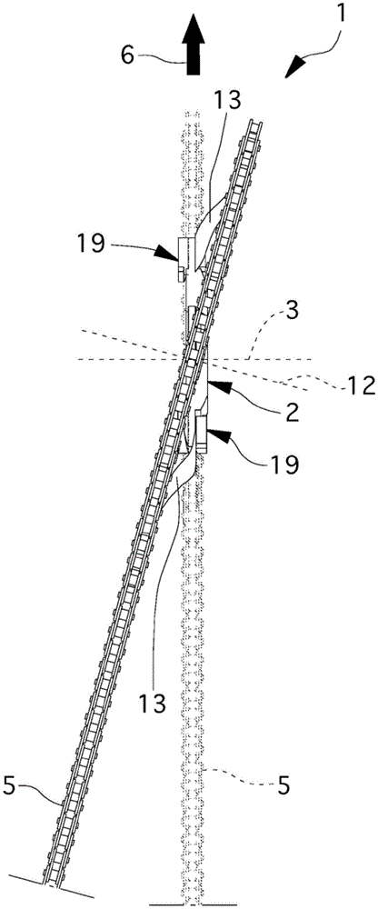
图4和图5是根据本发明的装置的两种不同工作构型的示意图。Figures 4 and 5 are schematic views of two different working configurations of the device according to the invention.
具体实施方式Detailed ways
参看诸图,自行车传动装置均由标号1标示。Referring to the figures, bicycle transmissions are designated by reference numeral 1 .
装置1包括连接核心2,该连接核心2能够以可绕旋转轴线3旋转的方式与自行车车架相关联,为简明起见,图中未绘出自行车车架。The device 1 comprises a connecting
具体而言,连接核心2所位于的平面在自行车移动期间应保持固定不变。Specifically, the plane in which the connecting
此外,装置1包括齿圈4,其位于定位平面11上,围绕连接核心2,且能够耦联到闭合环形的柔韧传动元件5,以使自行车开始沿向前运动方向6运动。Furthermore, the device 1 comprises a
在图中所示的实施例中,装置1是具有非圆形外形的齿轮,特别适于使蹬车时施加的推力最大化。In the embodiment shown in the figures, the device 1 is a gear having a non-circular profile, particularly suitable for maximizing the thrust applied when pedalling.
本发明也涵盖齿圈具有不同形状(例如,圆形)的不同解决方案。The invention also covers different solutions in which the ring gear has a different shape (eg circular).
仍然参看本发明实施例,连接核心2是装置1的部分,其与牙盘系统7相关联,用于使自行车开始运动。Still referring to the embodiment of the present invention, the connecting
牙盘系统7由两个曲柄9构成,该两个曲柄9布置在连接核心2的对侧,角位置相差180度,且通过圆柱形元件8(即,“花鼓”)连接为一体。The
花鼓8的轴线与旋转轴线3重合,且在骑行过程中应保持恒定不变。The axis of the
通过用特殊的踏板推动曲柄9,扭力传递到花鼓8,接着传递到连接核心2,从而使齿轮旋转。为了简明起见,图中未绘出踏板。By pushing the
通过这种方式,齿圈4带动柔韧传动元件5,即,“链条”。In this way, the
链条5的链环实际上耦联到齿圈4的齿,由于齿圈4的旋转,链条本身也被带动。The links of the
根据本发明,装置1包括摆动构件10,其位于连接核心2和齿圈4之间。According to the invention, the device 1 comprises a rocking
摆动构件10能使定位平面11相对于旋转轴线3倾斜。The rocking
在维持旋转轴线3的位置固定不变的同时,装置1还使得齿圈4的定位平面11的倾角可变。While maintaining the position of the
通过这种方式,当链条5啮合到与齿圈4不对准的后齿轮时,齿圈4摆动,从而使链条自身呈笔直构型而不发生显著变形,因而使摩擦最小化。In this way, when the
此外,当自行车使用者决定通过换档(因此,将链条从一个位置移位到另一位置)来改变齿比时,此技术特征也特别有用。In addition, this technical feature is also particularly useful when the user of the bicycle decides to change the gear ratio by shifting (thus, shifting the chain from one position to another).
定位平面11的倾斜实际上可使齿圈4对链条的移位做出适应性变化,从而使阻力最小化。The inclination of the
在图中,定位平面11的法线方向12相对于旋转轴线3的关系突出表现了该倾斜。This inclination is highlighted in the figure by the relationship of the
在图中所示的实施例中,摆动构件10包括至少一个柔性体13,其能使齿圈4相对于连接核心2的位置发生变化。In the embodiment shown in the figures, the rocking
具体而言,摆动构件10包括多个呈拉长薄板形状的柔性体13。Specifically, the
更具体而言,齿圈具有带齿的外周边14和大体上圆形的内周边15,且柔性体大体上沿内周边延伸。More specifically, the ring gear has a toothed
柔性体13包括与连接核心2相关联的第一末端16和与齿圈4相关联的第二末端17。The
参考当自行车运动时装置1的旋转方向,第一末端16在旋转中领先于第二末端17,以便可将运动从连接核心2传递到齿圈4,且避免因柔性体本身的滑移和失稳而造成的变形。Referring to the rotation direction of the device 1 when the bicycle is in motion, the
这是因为,借助于这种方式,在旋转中,连接核心2可通过对柔性体13施加拉伸应力而不是施加压缩应力来带动柔性体13。This is because, in this way, during rotation, the connecting
摆动构件10还包括控制构件18,该控制构件能够将定位平面11相对于旋转轴线3的倾斜限制在第一极限位置和第二极限位置之间。The rocking
本发明还涵盖第一极限位置与第二极限位置重合,从而在这一情况下使定位平面11的倾角等于零的特殊构型。The invention also covers a special configuration in which the first limit position coincides with the second limit position, so that in this case the inclination of the
有利地,控制构件18包括至少一个锁定元件19,所述锁定元件19安装在齿圈4上(图1和图2)或安装在连接核心2上(图3),并且可调节为第一构型或第二构型,在所述第一构型中,锁定元件19与连接核心2接触(图1和图2)或与齿圈4接触(图3),以防止齿圈4位移,另一方面,在所述第二构型中,锁定元件19与连接核心2间隔开(图1和图2)或与齿圈4间隔开(图3),以允许齿圈4位移。Advantageously, the
锁定元件19具有调节部分21,所述调节部分21能够调节齿圈4相对于连接核心2的偏差。The locking
在图1和图2中所示的解决方案中,锁定元件19包括握把部分20,从而能够将锁定元件本身固定到齿圈4。In the solution shown in FIGS. 1 and 2 , the locking
具体而言,锁定元件19借助于握把部分20固定到与第二末端17中的一个相对应的齿圈4和柔性体13,同时调节部分21布置在与第一末端16中的一个相对应的位置。In particular, the locking
有利地,调节部分21包括调节螺丝,经适当调节后,所述调节螺丝抵靠柔性体13的柔性较小的部分,因而限制柔性体末端的行程。Advantageously, the
本发明还涵盖调节部分21不具有调节螺丝,因而最大摆动是例如在各组件的组装阶段或其实现阶段加以预先确定的解决方案。The invention also contemplates that the
另一方面,在图3所示的解决方案中,锁定元件19包括安装在连接核心2上的半圆形段,且调节部分21由形成于半圆形段上的斜面界定。On the other hand, in the solution shown in FIG. 3 , the locking
通过旋转半圆形段,斜面21的表面靠近或远离齿圈4,并且改变齿圈4相对于连接核心2的最大偏差。By rotating the semicircular segment, the surface of the
控制构件18包括至少一对锁定元件19,所述锁定元件19布置在定位平面11的对侧。The
在图示的实施例中,控制构件包括两对锁定元件19,所述两对锁定元件19布置在两个不同角位置。In the illustrated embodiment, the control member comprises two pairs of locking
相对于连接核心2的旋转中心,两个锁定元件19布置在两个相邻柔性体13处。Two locking
通过这种方式,在两个柔性体13的各一个末端和旋转中心处实现三点固定,以便在改变定位平面11的倾角时自动固定可能的平面束,且防止定位平面11相对于除旋转轴线3外的其它方向的任何倾斜。In this way, a three-point fixation is achieved at each end of the two
控制构件18还包括至少一个固定元件22,其将锁定元件19固定到齿圈4。The
具体而言,固定元件22为螺丝类型的固定元件,且能够精确地定位和固定锁定元件19。Specifically, the fixing
在图1和图2所示的第一实施例中,摆动构件10包括薄板形元件23,该薄板形元件23分为与连接核心2相关联的中心部分24和界定柔性体13的外围部分25。In the first embodiment shown in FIGS. 1 and 2 , the rocking
在此情况下,连接核心2包括薄板形元件23的最内部且柔性较小的部分,圆形法兰26摩擦夹紧薄板形元件23。In this case, the connecting
圆形法兰26借助于螺栓27固定到薄板形元件,且连接到圆柱形元件8。The
本发明还涵盖薄板形元件23与圆形法兰26之间的连接仅通过连接元件实现而不发生摩擦夹紧的解决方案。The invention also covers a solution in which the connection between the thin plate-shaped
柔性体13具有直接从连接核心2延伸的第一末端16和与齿圈4相关联的第二末端17。The
具体而言,柔性体13不是分离的实体,而是直接成形于薄板形元件23上。Specifically, the
在图3所示的第二实施例中,连接核心2由从中心呈径向图案延伸的硬质元件构成。In the second embodiment shown in Figure 3, the connecting
柔性体13是分离的实体,其第一末端通过锁定元件19与连接核心2的各自的末端相关联,而第二末端与齿圈4相关联。The
本发明的操作过程如下。The operation of the present invention is as follows.
来自牙盘系统7的扭力使装置1旋转。Torsion from the
在旋转时,齿圈4带动柔韧传动元件5,柔韧传动元件又使自行车移动。During rotation, the
在运动中,链条5对齿圈4施力,这使得柔性体13弯曲,因此引起齿圈4相对于连接核心2的移位,以及定位平面11的倾斜。During the movement, the
借助于对调节部分21的调节,锁定元件19可决定最大倾斜。By means of the adjustment of the
在这种意义上,锁定元件19是能将齿圈4的移位限制在由锁定元件19确定的极限范围内的“终端止挡器”。In this sense, the locking
本发明还涵盖调节部分21已经过预设,因此无需进行调节的解决方案。The present invention also covers solutions in which the
前述实施例中所述的装置1在单齿轮系统(即,具有单个前齿轮)的情况下特别有利。本发明还涵盖设有若干个齿轮,其中齿圈4可相对于各自的连接核心2倾斜的解决方案。The device 1 described in the preceding embodiments is particularly advantageous in the case of a single gear system (ie with a single front gear). The invention also covers solutions with several gears, wherein the
在实务中,已发现本发明实现了预定目标,尤其要强调地是,本发明的自行车传动装置使得便于改变齿比,且能使由链条相对于固定零件的倾斜造成的摩擦最小化。In practice, the invention has been found to achieve the intended objectives, in particular, the bicycle transmission of the invention makes it easy to change the gear ratios and minimizes friction caused by the inclination of the chain relative to the fixed parts.
齿圈的定位平面的倾斜实际上有助于柔韧元件或链条在齿比改变时从一个位置移位到另一个位置。The inclination of the positioning plane of the ring gear actually helps the flexible element or chain to shift from one position to another when the gear ratio changes.
此倾斜还允许减少齿圈本身对链条施加的作用力的阻力,因而使使用者更省力。阻力的减小以及传动系统操作的改良使得能够显著减少齿圈的齿与链条的连接处的摩擦和应力。This inclination also allows reducing the resistance of the ring gear itself to the force exerted by the chain, thus making it easier for the user. The reduction in drag and the improvement in the operation of the drive train make it possible to significantly reduce friction and stress at the connection of the teeth of the ring gear to the chain.
因此,可防止齿的弯曲和/或相接触的零件的磨损,从而使所涉及的元件破损的风险减至最小,并获得与维护作业减少相关的好处。Thus, bending of the teeth and/or wear of the parts in contact can be prevented, thereby minimising the risk of breakage of the components involved and obtaining benefits associated with reduced maintenance work.
归功于本发明装置的柔韧性,本发明装置还能防止链条脱落。Thanks to the flexibility of the device of the present invention, the device of the present invention also prevents the chain from falling off.
最后,由于车架可能会经受由运动员施加的强劲推进力引发的高扭力和弯曲度,齿圈的摆动使得能够解决牙盘旋转轴线相对于车轮旋转轴线倾斜的问题。Finally, the swinging of the ring gear makes it possible to solve the problem of tilting the axis of rotation of the crankset relative to the axis of rotation of the wheel, since the frame may experience high torsion and flex due to the strong propulsion applied by the athlete.
因链条保持对准,故而有助于平顺的骑行,且可防止发生会影响比赛发挥的故障。Because the chain stays aligned, it contributes to a smooth ride and prevents failures that could affect the performance of the race.
Claims (10)
Applications Claiming Priority (3)
| Application Number | Priority Date | Filing Date | Title |
|---|---|---|---|
| ITUB2015A003217A ITUB20153217A1 (en) | 2015-08-25 | 2015-08-25 | DEVICE FOR TRANSMISSION OF MOTORCYCLES TO SPEEDS |
| ITUB2015A003217 | 2015-08-25 | ||
| PCT/IB2016/053625 WO2017033068A1 (en) | 2015-08-25 | 2016-06-17 | Device for motion transmission on cycles |
Publications (2)
| Publication Number | Publication Date |
|---|---|
| CN108137125A CN108137125A (en) | 2018-06-08 |
| CN108137125B true CN108137125B (en) | 2020-09-15 |
Family
ID=54705739
Family Applications (1)
| Application Number | Title | Priority Date | Filing Date |
|---|---|---|---|
| CN201680060965.7A Active CN108137125B (en) | 2015-08-25 | 2016-06-17 | bicycle transmission |
Country Status (6)
| Country | Link |
|---|---|
| US (1) | US10668981B2 (en) |
| EP (1) | EP3341280B1 (en) |
| JP (1) | JP6839191B2 (en) |
| CN (1) | CN108137125B (en) |
| IT (1) | ITUB20153217A1 (en) |
| WO (1) | WO2017033068A1 (en) |
Families Citing this family (3)
| Publication number | Priority date | Publication date | Assignee | Title |
|---|---|---|---|---|
| CN110884607A (en) * | 2018-09-11 | 2020-03-17 | 天心工业股份有限公司 | Transmission system of bicycle and fluted disc mounting structure thereof |
| DE102023101411A1 (en) * | 2023-01-20 | 2024-07-25 | Alfred Thun GmbH | Drive system for a bicycle |
| ES1305621Y (en) * | 2023-11-08 | 2024-04-30 | Juarez Perez Enrique | Steerable transmission system |
Family Cites Families (26)
| Publication number | Priority date | Publication date | Assignee | Title |
|---|---|---|---|---|
| FR1019930A (en) * | 1950-04-15 | 1953-01-29 | Application of the flector in the control of transmission of parts not aligned in the same plane and mounted on two parallel shafts, mainly for bicycles and all similar devices | |
| GB1087559A (en) | 1963-12-23 | 1967-10-18 | Mark Hattan | Bicycle drive |
| JPS5451150A (en) * | 1977-09-27 | 1979-04-21 | Daburiyuu Burauningu Buruusu | Sprocket shifting device |
| DE3141296A1 (en) * | 1981-10-17 | 1983-04-28 | Fichtel & Sachs Ag, 8720 Schweinfurt | Self-aligning chain wheel |
| US5205794A (en) * | 1983-11-14 | 1993-04-27 | Bicycle Partnership #1 | Shift mechanism for bicycle |
| FR2590223B1 (en) * | 1985-11-21 | 1988-06-03 | Gallee Bernard | DEVICE FOR TRANSMITTING IRREGULAR CIRCULAR EFFORTS TO A CHAIN THROUGH A DEFORMABLE PLATE |
| JP2529262B2 (en) | 1987-05-21 | 1996-08-28 | 株式会社シマノ | Bicycle drive gear |
| CN87209772U (en) * | 1987-06-29 | 1988-04-06 | 陈纪枫 | Automatic 16 grades speed variator of bicycle |
| US5927149A (en) * | 1995-07-14 | 1999-07-27 | The United States Of America As Represented By The Secretary Of The Navy | High-torque quiet gear |
| KR0161226B1 (en) * | 1996-06-19 | 1998-12-01 | 민영순 | Power train apparatus for a bicycle |
| US6173982B1 (en) * | 1998-08-19 | 2001-01-16 | W. David Westergard | Self aligning crank assembly and method |
| KR100290299B1 (en) * | 1998-12-22 | 2001-05-15 | 이재화 | Sprocket Drive of Bicycle |
| US7462120B1 (en) * | 2005-02-03 | 2008-12-09 | Thompson Scott C | Warped chain ring gear used in a bicycle chain transfer |
| ITMI20061549A1 (en) * | 2006-08-03 | 2008-02-04 | Campagnolo Srl | ASSEMBLY OF RIGHT PEDESTAL FOR BICYCLE AND RELATED PEDIVELLA AND CORONA |
| DE102006057168B4 (en) * | 2006-12-01 | 2018-07-12 | Sram Deutschland Gmbh | sprocket |
| CN201875095U (en) * | 2010-12-13 | 2011-06-22 | 林君毅 | Elastic gear |
| EP2729352A4 (en) * | 2011-07-08 | 2015-08-05 | Paha Designs Llc | Floating front ring |
| AT510717B1 (en) * | 2011-07-27 | 2012-06-15 | Schuster Gregor | MECHANICS FOR TRANSMITTING A TURNING MOVEMENT WITH A CHANGED TRANSLATION |
| CN202326991U (en) * | 2011-11-28 | 2012-07-11 | 重庆赛特尔机械有限公司 | Damping sprocket of motorcycle |
| US9725132B2 (en) * | 2014-03-26 | 2017-08-08 | Shimano Inc. | Bicycle crank assembly |
| AT516330B1 (en) * | 2014-09-01 | 2016-06-15 | Gregor Schuster | Control of a transmission with segmented wheels by means of electrical control elements |
| DE102015016263A1 (en) * | 2015-12-15 | 2017-06-22 | Sram Deutschland Gmbh | Kettering |
| US9957852B2 (en) * | 2016-06-14 | 2018-05-01 | Delphi Technologies Ip Limited | Cushion ring assembly for a sprocket driven by a chain |
| US9944347B2 (en) * | 2016-07-21 | 2018-04-17 | Sram, Llc | Pivoting chainring assembly |
| US9879752B1 (en) * | 2016-10-28 | 2018-01-30 | David Hicken | Spring loaded sprocket carrier |
| US20190162287A1 (en) * | 2017-11-28 | 2019-05-30 | Yoichiro Hamamoto | Rotation transmission mechanism, bicycle provided with rotation transmission mechanism, and elastically-deformable body used in rotation transmission mechanism |
-
2015
- 2015-08-25 IT ITUB2015A003217A patent/ITUB20153217A1/en unknown
-
2016
- 2016-06-17 EP EP16741681.7A patent/EP3341280B1/en active Active
- 2016-06-17 US US15/755,409 patent/US10668981B2/en active Active
- 2016-06-17 CN CN201680060965.7A patent/CN108137125B/en active Active
- 2016-06-17 JP JP2018529751A patent/JP6839191B2/en not_active Expired - Fee Related
- 2016-06-17 WO PCT/IB2016/053625 patent/WO2017033068A1/en not_active Ceased
Also Published As
| Publication number | Publication date |
|---|---|
| EP3341280B1 (en) | 2023-07-26 |
| EP3341280C0 (en) | 2023-07-26 |
| JP2018525281A (en) | 2018-09-06 |
| ITUB20153217A1 (en) | 2017-02-25 |
| WO2017033068A1 (en) | 2017-03-02 |
| CN108137125A (en) | 2018-06-08 |
| US10668981B2 (en) | 2020-06-02 |
| US20180244344A1 (en) | 2018-08-30 |
| JP6839191B2 (en) | 2021-03-03 |
| EP3341280A1 (en) | 2018-07-04 |
Similar Documents
| Publication | Publication Date | Title |
|---|---|---|
| TWI255249B (en) | Shift assist projection for bicycle sprocket | |
| CN108688771B (en) | Rear speed variator for bicycle | |
| US5882025A (en) | Bicycle with rhombus-like gear with circularly curved apexes | |
| TWI669242B (en) | Bicycle transmission apparatus | |
| US5970822A (en) | Unidirectional output from bi-directional inputs bicycle transmission | |
| US7153229B2 (en) | Chain alignment structure of bicycle transmission | |
| US20070213150A1 (en) | Automatic transmission for multi-speed bicycle | |
| US5224725A (en) | Two-wheeled-drive two wheeled vehicle | |
| TW200410864A (en) | Top pull type front derailleur | |
| EP0130972A1 (en) | Automatic variable speed transmission | |
| CN108137125B (en) | bicycle transmission | |
| TW201825350A (en) | Rear derailleur | |
| JPH05508367A (en) | motorcycle | |
| US5871221A (en) | Driving apparatus for bicycles and the like | |
| CN107554682B (en) | Bicycle tensioner device and bicycle tensioner | |
| US7736253B2 (en) | Gear-shifting apparatus for a bicycle, and bicycle incorporating same | |
| EP2679480B1 (en) | Vehicle | |
| JP2022547827A (en) | Motorcycle propulsion device | |
| US20250074543A1 (en) | Bicycle drivetrain and bicycle including the same | |
| US10094452B1 (en) | Continuously variable transmission for a bicycle | |
| JP5648150B1 (en) | Bicycle gear device and bicycle | |
| CN114954774B (en) | Rear derailleur and variable speed bicycle | |
| WO2018178898A1 (en) | Automatic transmission for bicycles | |
| TW202515775A (en) | Crank assembly for a bicycle | |
| JPS6231356Y2 (en) |
Legal Events
| Date | Code | Title | Description |
|---|---|---|---|
| PB01 | Publication | ||
| PB01 | Publication | ||
| SE01 | Entry into force of request for substantive examination | ||
| SE01 | Entry into force of request for substantive examination | ||
| GR01 | Patent grant | ||
| GR01 | Patent grant | ||
| TR01 | Transfer of patent right | ||
| TR01 | Transfer of patent right |
Effective date of registration: 20230526 Address after: Rovereto (TN) 2 38068 Industrial Avenue Patentee after: Metal Systems Co.,Ltd. Address before: Italy Rowe Reto Patentee before: Briosi Antonello |