CN108136593B - Robot arm and robot wrist - Google Patents
Robot arm and robot wrist Download PDFInfo
- Publication number
- CN108136593B CN108136593B CN201680048400.7A CN201680048400A CN108136593B CN 108136593 B CN108136593 B CN 108136593B CN 201680048400 A CN201680048400 A CN 201680048400A CN 108136593 B CN108136593 B CN 108136593B
- Authority
- CN
- China
- Prior art keywords
- wrist
- hgv
- robot
- axis
- rotation
- Prior art date
- Legal status (The legal status is an assumption and is not a legal conclusion. Google has not performed a legal analysis and makes no representation as to the accuracy of the status listed.)
- Active
Links
Images


Classifications
-
- B—PERFORMING OPERATIONS; TRANSPORTING
- B25—HAND TOOLS; PORTABLE POWER-DRIVEN TOOLS; MANIPULATORS
- B25J—MANIPULATORS; CHAMBERS PROVIDED WITH MANIPULATION DEVICES
- B25J17/00—Joints
- B25J17/02—Wrist joints
- B25J17/0283—Three-dimensional joints
- B25J17/0291—Three-dimensional joints having axes crossing at an oblique angle, i.e. other than 90 degrees
-
- B—PERFORMING OPERATIONS; TRANSPORTING
- B25—HAND TOOLS; PORTABLE POWER-DRIVEN TOOLS; MANIPULATORS
- B25J—MANIPULATORS; CHAMBERS PROVIDED WITH MANIPULATION DEVICES
- B25J17/00—Joints
- B25J17/02—Wrist joints
- B25J17/0283—Three-dimensional joints
-
- B—PERFORMING OPERATIONS; TRANSPORTING
- B25—HAND TOOLS; PORTABLE POWER-DRIVEN TOOLS; MANIPULATORS
- B25J—MANIPULATORS; CHAMBERS PROVIDED WITH MANIPULATION DEVICES
- B25J13/00—Controls for manipulators
- B25J13/08—Controls for manipulators by means of sensing devices, e.g. viewing or touching devices
- B25J13/085—Force or torque sensors
-
- B—PERFORMING OPERATIONS; TRANSPORTING
- B25—HAND TOOLS; PORTABLE POWER-DRIVEN TOOLS; MANIPULATORS
- B25J—MANIPULATORS; CHAMBERS PROVIDED WITH MANIPULATION DEVICES
- B25J18/00—Arms
- B25J18/02—Arms extensible
- B25J18/04—Arms extensible rotatable
-
- B—PERFORMING OPERATIONS; TRANSPORTING
- B25—HAND TOOLS; PORTABLE POWER-DRIVEN TOOLS; MANIPULATORS
- B25J—MANIPULATORS; CHAMBERS PROVIDED WITH MANIPULATION DEVICES
- B25J9/00—Programme-controlled manipulators
- B25J9/02—Programme-controlled manipulators characterised by movement of the arms, e.g. cartesian coordinate type
- B25J9/04—Programme-controlled manipulators characterised by movement of the arms, e.g. cartesian coordinate type by rotating at least one arm, excluding the head movement itself, e.g. cylindrical coordinate type or polar coordinate type
- B25J9/046—Revolute coordinate type
-
- B—PERFORMING OPERATIONS; TRANSPORTING
- B25—HAND TOOLS; PORTABLE POWER-DRIVEN TOOLS; MANIPULATORS
- B25J—MANIPULATORS; CHAMBERS PROVIDED WITH MANIPULATION DEVICES
- B25J9/00—Programme-controlled manipulators
- B25J9/06—Programme-controlled manipulators characterised by multi-articulated arms
-
- B—PERFORMING OPERATIONS; TRANSPORTING
- B25—HAND TOOLS; PORTABLE POWER-DRIVEN TOOLS; MANIPULATORS
- B25J—MANIPULATORS; CHAMBERS PROVIDED WITH MANIPULATION DEVICES
- B25J9/00—Programme-controlled manipulators
- B25J9/10—Programme-controlled manipulators characterised by positioning means for manipulator elements
- B25J9/12—Programme-controlled manipulators characterised by positioning means for manipulator elements electric
- B25J9/126—Rotary actuators
Landscapes
- Engineering & Computer Science (AREA)
- Robotics (AREA)
- Mechanical Engineering (AREA)
- Human Computer Interaction (AREA)
- Manipulator (AREA)
Abstract
The invention relates to a robot arm and a robot wrist. The robot arm comprises a number N of actuator drivable, via arm segments GLiSerially connected articulated GVnN1, 2, 1., N and i 1, 2., N-1, and N ≧ 6, the proximal arm segment GL of the robot arm1Articulated GV1Connected to the robot body, distal arm section GLN‑1Articulated GVNConnected to the actuator E, an arm section GL of the robot armN‑1And GLN‑2Articulated GVN‑1Connecting and arm section GLN‑2And GLN‑3Articulated GVN‑2Are connected, and each joint is connected with a GVN,GVN‑2,GVN‑2Allowing to surround the corresponding rotation axis RGV,N,RGV,N‑1,RGV,N‑2The movement of (2). The robot arm is embodied such that the rotation axis RGV,N‑2And RGV,N‑1Intersecting or rotational axis R at an angle in the range of 50-130 degGV,N‑2And RGV,N‑1Having a minimum spacing A1, the axes of rotation R, from each other in the range of 1mm to 20mmGV,NRadially at a constant distance D1 relative to the axis of rotation RGV,N‑1Set up and articulate the GVN‑1For detecting forces or about the axis of rotation RGV,N‑1A torque sensor of (2).
Description
Technical Field
The invention relates to a robot arm having a plurality of arm sections, which are each connected via an actuator-drivable articulation (Gelenkverbunding), wherein a proximal arm section of the robot arm can be connected via an articulation to a robot body and a distal arm section of the robot arm can be connected via an articulation to a mountable actuator (Effektor). At least the last three joints of the distal end of the robot arm allow rotation about the axis of rotation, respectively. Such robot arms are known in the prior art.
The invention further relates to a robot wrist (roboteerhanddge) having three actuator-drivable wrist joints, which are connected in series via two wrist sections, wherein a proximal wrist section of the robot wrist can be connected to the robot arm via one of the wrist joints, a distal wrist section of the robot wrist can be connected to the actuator via the other wrist joint, and each of the three wrist joints allows movement about a corresponding axis of rotation. Such robot wrists are known in the art.
The invention finally relates to a robot having a robot arm or a robot wrist.
Disclosure of Invention
It is an object of the present invention to design a robot arm or a robot wrist so as to improve the operation of the robot arm/robot wrist, in particular for the operation of the surroundings on/above an object or a work surface.
The invention can be derived from the features of the independent claims. Advantageous embodiments and configurations are the subject matter of the dependent claims. Further features, application possibilities and advantages of the invention can be derived from the following description and the description of the embodiments of the invention shown in the drawings.
In order to solve the above-mentioned object, a first aspect proposes an actuator-drivable articulation GV having a number NnOf the robot arm, these joints being connected via arm sections GLiA series connection, where N is 1, 2,., N and i is 1, 2., N-1, and N ≧ 6, wherein an arm segment GL of the proximal end of the robot arm1Can be connected by articulation GV1An arm segment GL connected to the robot body and at the distal end of the robot armN-1Articulated GVNConnected to the actuator E, an arm section GL of the robot armN-1And GLN-2Articulated GVN-1Arm segment GL of a connected and robotic armN-2And GLN-3Articulated GVN-2Connected, and articulated to GVN,GVN-1,GVN-2Each of which allows to surround a corresponding rotation axis RGV,N,RGV,N-1,RGV,N-2The movement of (2).
Distal articulation GVN,GVN-1,GVN-2Connected with joint GLN-2,GLN-1To a certain extent forming a "wrist" which is opposite to the preceding joint GLN-3.. orientation of the actuator E in three degrees of freedom is achieved.
The proposed robot arm is characterized in that it is embodied such that the axis of rotation RGV,N-2And RGV,N-1Intersect at an angle in the range of 50-130 deg., or axis of rotation RGV,N-2And RGV,N-1Having a minimum spacing A1 from each other in the range of 1-20mm, the axis of rotation RGV,NRadially at a constant distance D1 relative to the axis of rotation RGV,N-1Set up and articulate the GVN-1Arranged for sensing forces or about the axis of rotation RGV,N-1Or (or a torque that effectively acts about the axis).
Axis of rotation RGV,N-2And RGV,N-1Preferably 2mm, 5mm, 7mm, 10mm, 12mm, 15mm or 17 mm. Axis of rotation RGV,N-2And RGV,N-1The angle of intersection preferably ranges from 50 to 130 °, 60 to 120 °, 70 to 110 °, 80 to 100 °, or 85 to 95 °.
For detecting the force or torque, known output-side force or torque sensors can be present. The sensor can also be designed as a direct-drive. In the latter case, the direct drive may be both the drive and the sensor. Torque is typically estimated by engine current measurements in combination with known physical relationships. But the combination of both (direct drive and output side sensors to more accurately measure internal and external forces) cannot be completely excluded.
The aim is to improve the sensitivity to the acting torques and forces, in particular to the acting contact forces, by means of the acting lever.
Advantageously, the number N is equal to 6 or 7 or 8. It is particularly preferred that N is equal to 7. In the latter case (N ═ 7), the robot arm passes through the proximal arm section GL1Articulated GV via an articulation which is also drivable by an actuator1Connected to the robot body so as to be able to surround a total of 7 axes RGV1,RGV2,RGV3,RGV4,RGV5,RGV6And RGV7Controlling the robot arm and the actuator E. Having a rotational axis RGV5,RGV6,RGV7Three distal articulations of GV5,GV6,GV7And arm section GL5,GL6And actuator E may be collectively understood as a kind of "wrist". A 7-axis (N ═ 7) robot arm enables three-dimensional positioning and three-dimensional orientation of the end effector E in the working space of the robot. This means that the robot arm has a working space whose actuator E can reach each spatial point in any direction.
Advantageously, a proximal arm segment for three-dimensional positioning of the actuator E in the working space (for example, GL for N-6)1,GL2And GL3) Is a long arm section, so that the actuator E can be positioned in as large a working space as possible. Advantageously, the distal arm section (for example GL for N-6)4,GL5And GL6) Is a short arm section, thereby enabling the actuator E to achieve a desired orientation in a small spatial range.
The actuator (tool) E can be selected from one of several tools, such as a clamp, a welding torch, a welding tongs, a glue nozzle, a paint nozzle, a milling and drilling head, a gauge, a laser cutting head, a water jet cutting head, etc., according to the task and requirements. The actuator E can be directly connected with the joint GVNConnected or passed through (rigid)Of) a connector or adapter to an articulation GVNAre connected. The connecting element can be designed as a further arm section.
The proposed robot arm has several advantages. The lever, lifted by the distance D1 and a1, may improve the measurement of external forces or torque in almost all articulating angle joint (gelenkwenkelverbindenngen) configurations. Thus, even forces along the axis of rotation RGV,NActing, the distance D1 still achieves the effect of the joint GVN-1To identify external forces or torques. About the axis of rotation RGV,NIs also possible. Furthermore, in the proposed robot arm, the GV is connected at the wrist (distal joint)N,GVN-1,GVN-2And arm section GLN-2,GLN-1And actuator E) without classical singularities (kalasischen) ) Occurs because of the last two axes of rotation RGV,N-1And RGV,NAre not intersected. Another advantage is the reconfiguration of the wrist (Re-Konfiguration). This can to a large extent be achieved by movement of the wrist only, so that it is not necessary to move the entire robot arm.
Particularly advantageously, when the axis of rotation R isGV,N-2And RGV,NIn the case of an intersection, a movement of the robot arm and the actuator E about a so-called tool center point (TCP ═ a reference point defined at a suitable position on the tool/actuator) is possible in all robot arm configurations. Rotation axis R in current robot arm configurations even if there is no intersection pointGV,N-2And RGV,NThe closer they are arranged to each other, the rotation around the tool centre point can be implemented more easily.
The proposed robot arm advantageously enables a simple rotation around a tool center point if application scenarios of the robot arm are considered in which manipulation of an object should be performed on/over a work surface (e.g. a table top) by the robot arm comprising the implement E in the vicinity of the robot body (within the working area of the robot). This means that such rotation can be achieved to a large extent only by movement of the wrist, so that it is not necessary to move the entire robot arm in the workspace for the desired movement.
Overall, the proposed "wrist" of the robot arm or the entire robot arm enables a better detection of the acting external forces and moments, in particular during manual guidance of the wrist, for example for direct input (demonstration, teaching) movement processes, better handling of objects, in particular when working on/over a work surface, and ultimately a better and finer control of the handling of objects and the prevention of collisions of the robot arm with objects of the surroundings, by means of an efficient projection of the moments in the external forces and joint torques.
An advantageous embodiment of the robot arm is characterized in that the robot arm is embodied such that, in the case of various robot arm configurations, the axis of rotation RGV,NAt the position defined by the rotation axis RGV,N-2And RGV,N-1Projection onto an extended plane (rotation axis R of projection)GV,NX) and the axis of rotation RGV,N-1Enclosing an angle in the range of 50-130 deg..
An advantageous embodiment of the robot arm is characterized in that the axis of rotation RGV,N-2And a rotation axis RGV,N-1Enclosing an angle of 90 deg., and/or the axis of rotation RGV,NAt the position defined by the rotation axis RGV,N-2And RGV,N-1Projection onto an extended plane (rotation axis R of projection)GV,NX) and the axis of rotation RGV,N-1Enclosing an angle of 90 deg.. Advantageously, an angle suitable for a given angle, in particular an angle with a tolerance of ± 2 ° or ± 5 ° to 90 °, is used.
An advantageous embodiment of the robot arm is characterized in that the distance D1 is selected in the range from 10mm to 50cm, and is advantageously 15mm, 20mm, 50mm, 75mm, 1cm, 5cm, 10cm, 15cm, 20cm, 25cm, 30cm, 35cm, 40cm or 45 cm.
An advantageous embodiment of the robot arm is characterized in that the axis of rotation RGV,N-2And RGV,N-1Enclose into 90 °Angle and/or axis of rotation RGV,NAt the position defined by the rotation axis RGV,N-2And RGV,N-1Projection on the plane of expansion and axis of rotation RGV,N-1Enclosing an angle of 90 deg..
An advantageous embodiment of the robot arm is characterized in that it comprises an articulated connection GVN-2,GVN-1And GVNArm segment GLN-2And GLN-1And mounted on the articulated GVNPart of the robot arm of the actuator E is formed such that the arm section GLN-1And the actuator E is arranged around the axis of rotation RGV,N-1Is achievable unhindered in each posture.
An advantageous embodiment of the robot arm is characterized in that the joint GV is connected in an articulated mannerNHaving means for detecting force or about the axis of rotation RGV,NAnd/or articulation GVN-2Having means for detecting force or about the axis of rotation RGV,N-2A torque sensor of (2). Particularly advantageously, all the joints are connected to GVnAre designed to sense forces and/or about respective axes of rotation RGVnThe torque of (1). This allows a more precise detection of dynamically acting internal and external forces and moments of the robot arm, which improves the control of the robot arm and the recognition of collisions along the robot arm, for example, by means of corresponding model-based estimation methods.
An advantageous embodiment of the robot arm is characterized in that the robot arm is embodied such that the axis of rotation R isGV1And RGV2Intersecting, rotation axes R at an angle in the range of 50 to 130 DEGGV2And RGV3Intersecting, rotation axes R at an angle in the range of 50 to 130 DEGGV4Radially at a constant distance D2 from the axis of rotation RGV3Is arranged and the rotation axis RGV4And RGV5Intersecting at an angle in the range of 50 to 130 deg..
An advantageous embodiment of the robot arm is characterized in that the robot arm is embodied such that the axis of rotation R isGV1And RGV2Intersecting, rotational axes at an angle in the range of 50 to 130 °RGV2And RGV3Intersecting, rotation axes R at an angle in the range of 50 to 130 DEGGV3And RGV4Intersecting, rotation axes R at an angle in the range of 50 to 130 DEGGV5Radially at a constant distance D3 from the axis of rotation RGV4And (4) setting.
An advantageous embodiment of the robot arm is characterized in that the robot arm is embodied such that the axis of rotation R isGV1And RGV2Intersecting, rotation axes R at an angle in the range of 50 to 130 DEGGV2And RGV3Intersecting, rotation axes R at an angle in the range of 50 to 130 DEGGV4Radially at a constant distance D4 from the axis of rotation RGV3Setting, rotation axis RGV5Radially at a constant distance D5 from the axis of rotation RGV4And (4) setting.
The above embodiments relate in particular to the design of the robot arm starting from its proximal end. The different structural variants of the robot arm presented above can be selected according to the purpose of use and task settings and achieve an optimal detection of external forces and torques acting along the robot arm and a sensitive execution of movements.
According to a second aspect of the above object, the invention also relates to a wrist-coupled HGV drivable with three actuatorsnThe wrist joints are connected through two wrist sections HGLiConnected in series, where n is 1, 2, 3 and i is 1, 2, wherein the proximal wrist section HGL of the robot wrist1Can be connected with HGV through wrist joint1Connected to the robot arm, the distal wrist section HGL of the robot wrist2Can be connected with HGV through wrist joint3Connected to an actuator E, a wrist section HGL2And HGL1Articulating HGV2Connected and wrist-articulated to the HGV1,HGV2,HGV3Each allowing to rotate about a corresponding wrist rotation axis HRGV,1,HRGV,2,HRGV,3The movement of (2).
The proposed robot wrist is characterized in that the robot wrist is embodied such that the wrist rotation axis HR isHGV,1And HRHGV,2Intersect at an angle in the range of 50-130 DEG, or wrist rotation axis HRHGV,1And HRHGV,2Having a minimum spacing A1 from each other in the range of 1mm-20mm, the wrist axis of rotation HRHGV,3Radially at a constant distance D1 relative to the wrist rotation axis HRHGV,2Set up and wrist-articulate the HGV2For detecting forces or about the wrist rotation axis HRHGV,2A torque sensor of (2).
The proposed robot wrist allows three-dimensional orientation of the actuator E. The robot arm, which can be connected to the robot wrist, also allows a three-dimensional positioning of the wrist or the actuator E in the working area of the robot (robot arm, robot wrist and actuator E). A robot wrist composed of three distal wrist joints enables a sensitive interaction with a person and/or an object or a manipulation of an object, wherein the wrist is designed by the arrangement of the wrist rotation axis according to the invention and the sensing technology advantageously present in the wrist such that, on the one hand, external forces/torques can be sensitively recognized about all three axes, and, on the other hand, a high degree of mobility can be achieved largely only by a simple reconfiguration of the wrist, wherein both properties for manipulating objects in a working space, for example on/above a table top, can be utilized well.
An advantageous development of the robot wrist is characterized in that the robot wrist is embodied such that the wrist rotation axis HRHGV,3In the region defined by the wrist rotation axis HRHGV,1And HRHGV,2Projection on the plane of expansion and wrist rotation axis HRHGV,2Enclose an angle in the range of 50 deg. to 130 deg. with each other.
An advantageous development of the robot wrist is characterized in that the robot wrist is embodied such that the wrist rotation axis HRHGV,1And HRHGV,2Enclosing an angle of 90 ° and/or a wrist rotation axis HRHGV,3At a position defined by the rotation axis HRHGV,1And HRHGV,2Projection on the plane of expansion and wrist rotation axis HRHGV,2Enclose an angle of 90 deg. with each other.
An advantageous development of the robot wrist is characterized in that the robot wrist is embodied in such a way that the wrist is connected to the HGV1,HGV2,HGV3Wrist segment HGL1And HGL2And a wrist-mounted HGV3The actuator E on is formed such that the wrist section HGL2And the actuator E surrounds the wrist rotation axis HRHGV,2Is achievable unhindered in all positions of the robot arm.
An advantageous development of the robot wrist is characterized in that the robot wrist is embodied in such a way that the wrist is connected to the HGV3Arranged to sense forces or about the wrist rotation axis HRHGV,3And/or wrist-articulated HGV1Arranged to sense forces or about the wrist rotation axis HRHGV,1The torque of (1).
The advantages of the robot wrist and advantageous embodiments of the robot wrist can be derived from the transfer in the sense of the statements relating to the proposed robot arm and the like.
The invention finally also relates to a robot having a robot arm as described above.
Drawings
Further advantages, features and details can be derived from the following description, in which at least one embodiment is described in detail, if necessary with reference to the drawings. Identical, similar and/or functionally identical parts are provided with the same reference signs.
Figure 1 shows a highly schematic structure of a robot arm according to the invention with six degrees of freedom (N-6),
FIG. 2 shows a highly schematic structure of a robot wrist according to the invention, an
Fig. 3 shows a diagrammatic representation of an embodiment of a robot wrist according to the invention on a robot arm.
Detailed Description
Fig. 1 shows a highly schematic structure of a robot arm according to the invention with six degrees of freedom.
The robot arm has six actuatorsDrivable articulated GVnThese joints are connected via arm segments GLiA series connection, where n is 1, 2, 6 and i is 1, 2, 5. Proximal arm segment GL of a robot arm1Articulated GV1Is connected to the robot body RK. Distal arm section GL of a robot arm5Articulated GV6Is connected with an actuator E. The actuator E may be arranged directly at the articulation GV6On or set in the articulated GV6The adapter part is connected. Articulated GV4,GV5,GV6Each allowed to surround a corresponding rotation axis RGV,4,RGV,5,RGV,6The movement of (2). The part of the robot arm drawn with a dashed line forms the robot wrist. And arm section GL4,GL5Compared with the actuator E, the arm segment GL1,GL2And GL3With a greater longitudinal extension.
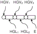
FIG. 2 shows a highly schematic structure of a robot wrist according to the present invention having three actuator drivable wrist joints HGVnThese wrist joints are connected by two wrist segments HGLiConnected in series, where n is 1, 2, 3 and i is 1, 2. Proximal wrist segment HGL of robot wrist1Connected with HGV through wrist joint1Is connected with the robot arm. Distal wrist segment HGL of robot wrist2Connected with HGV through wrist joint3Is connected with an actuator E. Wrist sector HGL2And HGL1Connecting HGVs by wrist joints2And (4) connecting. Wrist joint connection HGV1,HGV2,HGV3Each allowing to rotate about a corresponding wrist rotation axis HRGV,1,HRGV,2,HRGV,3And thus allows three-dimensional orientation of the actuator E in space.
Figure 3 shows a diagram of an embodiment of a robot wrist according to the invention on a robot arm. The robot wrist shown includes three actuator drivable wrist joints HGV1,HGV2And HGV3These wrist joints are connected by two wrist segments HGL1And HGL2Are connected in series. Near-end wrist joint connection HGL of robot wrist1Connected with HGV through wrist joint1Is connected with the robot arm. Distal end wrist joint of robot wrist connects HGL2Connected with HGV through wrist joint3Connected to an actuator E (not shown). Wrist sector HGL1And HGL2Connecting HGVs by wrist joints2And (4) connecting. Wrist joint connection HGV1,HGV2,HGV3Each allowing to rotate about a corresponding wrist rotation axis HRHGV,1,HRHGV,2,HRHGV,3And thus allows three-dimensional orientation of the actuator E in space.
The robot wrist is implemented such that the wrist rotation axis HRHGV,1And HRHGV,2Intersect at an angle of 90 DEG and for each arbitrary configuration of the robot wrist the wrist rotation axis HRHGV,3Radially with respect to the wrist rotation axis HRHGV,2A constant spacing D1. In addition, HGV is connected to all wrist joints1,HGV2And HGV3For detecting forces or about respective wrist rotation axes HRHGV,1,HRHGV,2,HRHGV,3The torque of (1).
Claims (15)
1. A robot arm having an enhanced sensitivity without generating singularities relating to moments and forces acting on the robot arm from the outside, the robot arm having a number N of actuator drivable articulation joints GVnThe articulation connecting the GVnThe transarm sector GLiAre connected in series, where N is 1, 2, 1, N and i is 1, 2, N-1, and N ≧ 6,
an arm section GL of the proximal end of the robot arm1Articulated GV1Can be connected with a robot main body RK,
an arm section GL of the distal end of the robot armN-1Articulated GVNCan be connected with an actuator E and can be connected with the actuator E,
arm section GLN-1And GLN-2Articulated GVN-1Connecting and arm section GLN-2And GLN-3Articulated GVN-2Are connected, and
-said articulation GVN,GVN-1,GVN-2Each of which allows to surround a corresponding rotation axis RGV,N,RGV,N-1,RGV,N-2The movement of (a) of (b),
characterized in that the robot arm is embodied such that
-said rotation axis RGV,N-2And RGV,N-1Intersecting at an angle in the range of 50-130,
-said rotation axis RGV,NRadially at a constant distance D1 relative to the axis of rotation RGV,N-1Is arranged, and
-said articulation GVN-1Arranged for sensing forces or about said axis of rotation RGV,N-1The torque of (1).
2. Robot arm according to claim 1, characterized in that the robot arm is embodied such that the axis of rotation R isGV,NAt the position defined by the rotation axis RGV,N-2And RGV,N-1Projection onto the plane of expansion and the axis of rotation RGV,N-1Enclose an angle in the range of 50 deg. to 130 deg. with each other.
3. Robot arm according to claim 1 or 2, characterized in that the rotation axis RGV,N-2And RGV,N-1Enclose an angle of 90 ° and/or the axis of rotation RGV,NAt the position defined by the rotation axis RGV,N-2And RGV,N-1Projection onto the plane of expansion and the axis of rotation RGV,N-1Enclosing an angle of 90 deg..
4. A robot arm according to any of the claims 1-3, characterized in that the distance D1 is selected in the range of 1-50 cm.
5. The robot arm according to any of the claims 1 to 4,comprising said articulated GVN-2,GVN-1And GVNThe arm section GLN-2And GLN-1And is mounted on the articulated GVNThe part of the robot arm of the actuator E is formed such that the arm segment GLN-1And the actuator E surrounds the axis of rotation RGV,N-1Can be realized unhindered in all postures of the robot arm.
6. A robot arm according to any of claims 1-5, characterized in that the articulation GVNArranged for sensing forces or about the axis of rotation RGV,NAnd/or the articulation GVN-2Arranged for sensing forces or about the axis of rotation RGV,N-2The torque of (1).
7. A robot arm according to any of claims 1-6, characterized in that the robot arm is implemented such that
-said rotation axis RGV1And RGV2Intersecting at an angle in the range of 50 to 130,
-said rotation axis RGV2And RGV3Intersecting at an angle in the range of 50 to 130,
-said rotation axis RGV4Radially at a constant distance D2 relative to the axis of rotation RGV3Is arranged, and
-said rotation axis RGV4And RGV5Intersecting at an angle in the range of 50 to 130 deg..
8. A robot arm according to any of claims 1-6, characterized in that the robot arm is implemented such that
-said rotation axis RGV1And RGV2Intersecting at an angle in the range of 50 to 130,
-said rotation axis RGV2And RGV3Intersecting at an angle in the range of 50 to 130,
-said rotation axis RGV3And RGV4Intersect at an angle in the range of 50 to 130 DEG, and
-said rotation axis RGV5Radially at a distance D3 relative to the axis of rotation RGV4And (4) setting.
9. A robot arm according to any of claims 1-6, characterized in that the robot arm is implemented such that
-said rotation axis RGV1And RGV2Intersecting at an angle in the range of 50 to 130,
-said rotation axis RGV2And RGV3Intersecting at an angle in the range of 50 to 130,
-said rotation axis RGV4Radially at a constant distance D4 relative to the axis of rotation RGV3Is arranged, and
-said rotation axis RGV5Radially at a distance D5 relative to the axis of rotation RGV4And (4) setting.
10. A robot wrist with enhanced dexterity without generating singularities related to moments and forces acting externally on the robot wrist having a three actuator drivable wrist articulation HGVnThe wrist joint is connected with HGVnVia two wrist segments HGLiAre connected in series, where n is 1, 2, 3 and i is 1, 2, where,
a wrist section HGL of a proximal end of the robot wrist1Can be connected with HGV through wrist joint1Is connected with the arm of the robot,
a wrist section HGL at the distal end of the robot wrist2Can be connected with HGV through wrist joint3Is connected with the actuator E and is provided with a plurality of actuators,
-said wrist section HGL2And HGL1Articulating HGV2Are connected, and
-said wrist articulation HGV1,HGV2,HGV3Each allowing to rotate about a corresponding wrist rotation axis HRHGV,1,HRHGV,2,HRHGV,3The movement of (a) of (b),
characterized in that the robot wrist is embodied such that
-said wrist rotation axis HRHGV,1And HRHGV,2Intersecting at an angle in the range of 50-130,
-said wrist rotation axis HRHGV,3Radially at a constant distance D1 relative to the wrist rotation axis HRHGV,2Is arranged, and
-said wrist articulation HGV2Arranged for detecting forces or about the axis of rotation of the wrist HRHGV,2The torque of (1).
11. A robot wrist according to claim 10, characterised in that the robot wrist is implemented such that the wrist rotation axis HRHGV,3In the region defined by the wrist rotation axis HRHGV,1And HRHGV,2Projection on the plane of deployment and said wrist rotation axis HRHGV,2Mutually enclose an angle in the range of 50 to 130 deg..
12. A robot wrist according to claim 10 or 11, characterised in that the wrist rotation axis HR is the axis HRHGV,1And HRHGV,2Enclose an angle of 90 ° and/or the wrist rotation axis HRHGV,3In the region defined by the wrist rotation axis HRHGV,1And HRHGV,2Projection on the plane of deployment and said wrist rotation axis HRHGV,2Enclose an angle of 90 deg. with each other.
13. A robot wrist according to any of claims 10 to 12, characterised in that the wrist is articulated with an HGV1,HGV2,HGV3The wrist section HGL1And HGL2And a wrist joint HGV attached to the wrist joint3Is formed such that the wrist section HGL2And said actuator E is arranged around said wrist rotation axis HRHGV,2Can be realized unhindered in all postures of the robot wrist.
14. A robot wrist according to any of claims 10 to 13, characterised in that the wrist is articulated with an HGV3Arranged for detecting forces or about the axis of rotation of the wrist HRHGV,3And/or the wrist joint is connected to the HGV1Arranged to sense forces or about said wrist rotation axis HRHGV,1The torque of (1).
15. A robot having a robot arm according to any of claims 1 to 9 or a robot wrist according to any of claims 10 to 14.
Applications Claiming Priority (3)
| Application Number | Priority Date | Filing Date | Title |
|---|---|---|---|
| DE102015113467.5A DE102015113467A1 (en) | 2015-08-14 | 2015-08-14 | Robotic arm and robot wrist |
| DE102015113467.5 | 2015-08-14 | ||
| PCT/EP2016/069060 WO2017029170A1 (en) | 2015-08-14 | 2016-08-10 | Robot arm and robot wrist |
Publications (2)
| Publication Number | Publication Date |
|---|---|
| CN108136593A CN108136593A (en) | 2018-06-08 |
| CN108136593B true CN108136593B (en) | 2021-10-15 |
Family
ID=56801509
Family Applications (1)
| Application Number | Title | Priority Date | Filing Date |
|---|---|---|---|
| CN201680048400.7A Active CN108136593B (en) | 2015-08-14 | 2016-08-10 | Robot arm and robot wrist |
Country Status (9)
| Country | Link |
|---|---|
| US (1) | US10836051B2 (en) |
| EP (1) | EP3334574B1 (en) |
| JP (1) | JP2018528085A (en) |
| KR (1) | KR102026785B1 (en) |
| CN (1) | CN108136593B (en) |
| DE (1) | DE102015113467A1 (en) |
| DK (1) | DK3334574T3 (en) |
| SG (1) | SG11201801260YA (en) |
| WO (1) | WO2017029170A1 (en) |
Families Citing this family (6)
| Publication number | Priority date | Publication date | Assignee | Title |
|---|---|---|---|---|
| JP6443875B2 (en) * | 2014-10-24 | 2018-12-26 | ライフロボティクス株式会社 | Robot arm mechanism |
| JP7087575B2 (en) * | 2018-03-30 | 2022-06-21 | 日本電産株式会社 | Posture adjustment method for 6-axis robot |
| JP6841802B2 (en) | 2018-08-31 | 2021-03-10 | ファナック株式会社 | Robots and robot systems |
| DE102019128082B4 (en) * | 2019-10-17 | 2022-03-10 | Franka Emika Gmbh | Torque-limited braking of a robotic manipulator |
| GB2592411B (en) * | 2020-02-27 | 2022-08-17 | Dyson Technology Ltd | Force sensing device |
| US11752518B2 (en) * | 2021-06-03 | 2023-09-12 | Sst Systems, Inc. | Robot-centered coating system with multiple curing workstations |
Citations (11)
| Publication number | Priority date | Publication date | Assignee | Title |
|---|---|---|---|---|
| EP1129828A1 (en) * | 2000-03-03 | 2001-09-05 | Dürr Systems GmbH | Robot for coating or treating workpieces |
| JP2004347548A (en) * | 2003-05-26 | 2004-12-09 | Ts Corporation | Load sensing system |
| JP2005199375A (en) * | 2004-01-14 | 2005-07-28 | Kawasaki Heavy Ind Ltd | Industrial robot |
| JP2006000955A (en) * | 2004-06-16 | 2006-01-05 | National Institute Of Advanced Industrial & Technology | Robot arm, and its rotating joint device and wrist device |
| JP2008073775A (en) * | 2006-09-19 | 2008-04-03 | Yaskawa Electric Corp | Industrial robot |
| JP2011101918A (en) * | 2009-11-10 | 2011-05-26 | Yaskawa Electric Corp | Robot and robot system |
| CN102395449A (en) * | 2009-04-15 | 2012-03-28 | Abb研究有限公司 | An apparatus for a robot arm |
| JP2012232361A (en) * | 2011-04-28 | 2012-11-29 | Seiko Epson Corp | Robot |
| JP2013010150A (en) * | 2011-06-28 | 2013-01-17 | Yaskawa Electric Corp | Robot and robot hand |
| CN203752148U (en) * | 2014-02-18 | 2014-08-06 | 中国人民解放军军事医学科学院卫生装备研究所 | Foldable light manipulator with joint axes in orthogonal relations and six degrees of freedom |
| CN104608127A (en) * | 2013-11-05 | 2015-05-13 | 库卡实验仪器有限公司 | Method for programming sequences of movements of a redundant industrial robot and associated industrial robot |
Family Cites Families (23)
| Publication number | Priority date | Publication date | Assignee | Title |
|---|---|---|---|---|
| JPH0261588U (en) * | 1988-10-24 | 1990-05-08 | ||
| KR950010972B1 (en) * | 1991-12-07 | 1995-09-26 | 포항종합제철주식회사 | Variable mechanism determinating method of robot |
| US5293107A (en) * | 1993-02-24 | 1994-03-08 | Fanuc Robotics North America, Inc. | Motorized rotary joint and method of constructing a modular robot utilizing same |
| JP3207728B2 (en) * | 1995-10-11 | 2001-09-10 | 三菱重工業株式会社 | Control method of redundant manipulator |
| JP2000141270A (en) | 1998-11-06 | 2000-05-23 | Matsushita Electric Ind Co Ltd | Articulated robot |
| DK3045273T3 (en) * | 2006-03-03 | 2019-02-25 | Universal Robots As | Joint for a robot |
| DE202007019624U1 (en) * | 2007-04-16 | 2014-07-29 | Schunk Gmbh & Co. Kg Spann- Und Greiftechnik | Drive unit and the drive unit comprehensive articulated arm |
| JP2008272883A (en) * | 2007-04-27 | 2008-11-13 | Yaskawa Electric Corp | Double-arm type robot manipulator |
| JP5135069B2 (en) * | 2008-06-12 | 2013-01-30 | 三鷹光器株式会社 | Medical instrument holding arm device |
| DE202010005313U1 (en) * | 2010-04-27 | 2011-10-27 | Kuka Laboratories Gmbh | processing device |
| WO2012073789A1 (en) * | 2010-11-30 | 2012-06-07 | オリンパス株式会社 | Master control input device and master-slave manipulator |
| EP2671689B1 (en) * | 2011-01-31 | 2015-02-25 | Toyota Jidosha Kabushiki Kaisha | Multi-joint arm robot, control method, and control program |
| JP5545263B2 (en) | 2011-04-27 | 2014-07-09 | 株式会社安川電機 | Robot system and workpiece manufacturing method |
| DE102012102749A1 (en) * | 2012-03-29 | 2013-10-02 | Reis Group Holding Gmbh & Co. Kg | Device and method for operating an industrial robot |
| JP5949917B2 (en) | 2012-06-19 | 2016-07-13 | 株式会社安川電機 | Robot system and method of manufacturing processed product |
| JP5713047B2 (en) | 2013-04-18 | 2015-05-07 | 株式会社安川電機 | Mobile robot, mobile robot positioning system, and mobile robot positioning method |
| JP2015142454A (en) * | 2014-01-29 | 2015-08-03 | キヤノン株式会社 | Actuator and multi-joint robot arm |
| US9981389B2 (en) * | 2014-03-03 | 2018-05-29 | California Institute Of Technology | Robotics platforms incorporating manipulators having common joint designs |
| JP6816721B2 (en) * | 2015-10-01 | 2021-01-20 | ソニー株式会社 | Medical support arm device and medical system |
| US10919149B2 (en) * | 2017-11-24 | 2021-02-16 | Denso Wave Incorporated | Controller for robot and inverse transforming method for robot |
| JP7087575B2 (en) * | 2018-03-30 | 2022-06-21 | 日本電産株式会社 | Posture adjustment method for 6-axis robot |
| JP2019177436A (en) * | 2018-03-30 | 2019-10-17 | 日本電産株式会社 | Robot control device, method for determining angle of joint of robot, and program |
| KR102284509B1 (en) * | 2019-07-25 | 2021-08-03 | 엘지전자 주식회사 | Charging robot and control method of the same |
-
2015
- 2015-08-14 DE DE102015113467.5A patent/DE102015113467A1/en not_active Ceased
-
2016
- 2016-08-10 KR KR1020187007407A patent/KR102026785B1/en active IP Right Grant
- 2016-08-10 US US15/752,705 patent/US10836051B2/en active Active
- 2016-08-10 JP JP2018509598A patent/JP2018528085A/en active Pending
- 2016-08-10 SG SG11201801260YA patent/SG11201801260YA/en unknown
- 2016-08-10 CN CN201680048400.7A patent/CN108136593B/en active Active
- 2016-08-10 EP EP16757173.6A patent/EP3334574B1/en active Active
- 2016-08-10 WO PCT/EP2016/069060 patent/WO2017029170A1/en active Application Filing
- 2016-08-10 DK DK16757173.6T patent/DK3334574T3/en active
Patent Citations (11)
| Publication number | Priority date | Publication date | Assignee | Title |
|---|---|---|---|---|
| EP1129828A1 (en) * | 2000-03-03 | 2001-09-05 | Dürr Systems GmbH | Robot for coating or treating workpieces |
| JP2004347548A (en) * | 2003-05-26 | 2004-12-09 | Ts Corporation | Load sensing system |
| JP2005199375A (en) * | 2004-01-14 | 2005-07-28 | Kawasaki Heavy Ind Ltd | Industrial robot |
| JP2006000955A (en) * | 2004-06-16 | 2006-01-05 | National Institute Of Advanced Industrial & Technology | Robot arm, and its rotating joint device and wrist device |
| JP2008073775A (en) * | 2006-09-19 | 2008-04-03 | Yaskawa Electric Corp | Industrial robot |
| CN102395449A (en) * | 2009-04-15 | 2012-03-28 | Abb研究有限公司 | An apparatus for a robot arm |
| JP2011101918A (en) * | 2009-11-10 | 2011-05-26 | Yaskawa Electric Corp | Robot and robot system |
| JP2012232361A (en) * | 2011-04-28 | 2012-11-29 | Seiko Epson Corp | Robot |
| JP2013010150A (en) * | 2011-06-28 | 2013-01-17 | Yaskawa Electric Corp | Robot and robot hand |
| CN104608127A (en) * | 2013-11-05 | 2015-05-13 | 库卡实验仪器有限公司 | Method for programming sequences of movements of a redundant industrial robot and associated industrial robot |
| CN203752148U (en) * | 2014-02-18 | 2014-08-06 | 中国人民解放军军事医学科学院卫生装备研究所 | Foldable light manipulator with joint axes in orthogonal relations and six degrees of freedom |
Also Published As
| Publication number | Publication date |
|---|---|
| EP3334574A1 (en) | 2018-06-20 |
| KR102026785B1 (en) | 2019-09-30 |
| DE102015113467A1 (en) | 2017-02-16 |
| WO2017029170A1 (en) | 2017-02-23 |
| EP3334574B1 (en) | 2021-03-10 |
| US10836051B2 (en) | 2020-11-17 |
| SG11201801260YA (en) | 2018-03-28 |
| JP2018528085A (en) | 2018-09-27 |
| CN108136593A (en) | 2018-06-08 |
| US20180243928A1 (en) | 2018-08-30 |
| KR20180099623A (en) | 2018-09-05 |
| DK3334574T3 (en) | 2021-06-14 |
Similar Documents
| Publication | Publication Date | Title |
|---|---|---|
| CN108136593B (en) | Robot arm and robot wrist | |
| CN107666875B (en) | Torque sensing for a surgical robot wrist | |
| CN104608127B (en) | Method for programming sequences of movements of a redundant industrial robot and associated industrial robot | |
| CN105073058B (en) | For positioning the system and method for manipulator arm by carrying out being engaged while occurring kernel movement in zero vertical space | |
| EP2671689B1 (en) | Multi-joint arm robot, control method, and control program | |
| CN104334110B (en) | Avoid manipulator arm using kernel to collide with patient | |
| US7445260B2 (en) | Gripping type hand | |
| JP2016516487A5 (en) | ||
| ES2424244T3 (en) | Procedure and device to regulate a manipulator | |
| Khan et al. | Force sensing in continuum manipulators using fiber bragg grating sensors | |
| US20110067521A1 (en) | Humanoid robot | |
| KR101498835B1 (en) | Control method for seven-shaft multi-joint robot, control program, and robot control device | |
| CN104334109A (en) | Systems and methods for commanded reconfiguration of a surgical manipulator using the null-space | |
| CN104718054A (en) | Phantom degrees of freedom for manipulating the movement of mechanical bodies | |
| JP7339806B2 (en) | Control system, robot system and control method | |
| JP5108032B2 (en) | Multi-joint structure teaching device | |
| WO2021111394A8 (en) | Orientation of user-input devices for controlling surgical arms | |
| JP2018528085A5 (en) | ||
| Abah et al. | A multi-modal sensor array for safe human-robot interaction and mapping | |
| AU2020375183B2 (en) | Robotic joint control | |
| JP3263939B2 (en) | Manipulator operation device | |
| JP7011426B2 (en) | Manipulator system | |
| CN112888398A (en) | Main robot and control method thereof | |
| KR20140140155A (en) | Multi-joint robot and method for controlling multi-joint robot | |
| JP4822067B2 (en) | Robot and its direct teaching device |
Legal Events
| Date | Code | Title | Description |
|---|---|---|---|
| PB01 | Publication | ||
| PB01 | Publication | ||
| SE01 | Entry into force of request for substantive examination | ||
| SE01 | Entry into force of request for substantive examination | ||
| GR01 | Patent grant | ||
| GR01 | Patent grant |