CN108106562B - Contact net measuring method and device - Google Patents
Contact net measuring method and device Download PDFInfo
- Publication number
- CN108106562B CN108106562B CN201711265064.4A CN201711265064A CN108106562B CN 108106562 B CN108106562 B CN 108106562B CN 201711265064 A CN201711265064 A CN 201711265064A CN 108106562 B CN108106562 B CN 108106562B
- Authority
- CN
- China
- Prior art keywords
- point
- line
- measured
- measuring
- measurement
- Prior art date
- Legal status (The legal status is an assumption and is not a legal conclusion. Google has not performed a legal analysis and makes no representation as to the accuracy of the status listed.)
- Active
Links
Images
Classifications
-
- G—PHYSICS
- G01—MEASURING; TESTING
- G01B—MEASURING LENGTH, THICKNESS OR SIMILAR LINEAR DIMENSIONS; MEASURING ANGLES; MEASURING AREAS; MEASURING IRREGULARITIES OF SURFACES OR CONTOURS
- G01B11/00—Measuring arrangements characterised by the use of optical techniques
- G01B11/26—Measuring arrangements characterised by the use of optical techniques for measuring angles or tapers; for testing the alignment of axes
-
- G—PHYSICS
- G01—MEASURING; TESTING
- G01B—MEASURING LENGTH, THICKNESS OR SIMILAR LINEAR DIMENSIONS; MEASURING ANGLES; MEASURING AREAS; MEASURING IRREGULARITIES OF SURFACES OR CONTOURS
- G01B11/00—Measuring arrangements characterised by the use of optical techniques
- G01B11/02—Measuring arrangements characterised by the use of optical techniques for measuring length, width or thickness
Landscapes
- Physics & Mathematics (AREA)
- General Physics & Mathematics (AREA)
- Length Measuring Devices By Optical Means (AREA)
Abstract
The invention provides a method and a device for measuring a contact net, wherein the method comprises the following steps: the method comprises the steps of obtaining a measured value of an included angle theta between a connecting line from a first measuring point to a measured point of the overhead line system and a connecting line from the first measuring point to a second measuring point, and obtaining a measured value of an included angle beta between a connecting line from the second measuring point to the measured point of the overhead line system and a connecting line from the second measuring point to the first measuring point; and determining the position of the measured point of the overhead line system according to the triangular relation operation by using the measured values of the theta and beta included angles and the distance value from the first measuring point to the second measuring point. The measurement accuracy, the measurement efficiency, the universality and the safety of the contact line of the contact network can be improved.
Description
Technical Field
The invention relates to the field of automatic measurement, in particular to a contact net measuring method and device.
Background
The overhead contact system for high-speed railway is a special power transmission line for supplying power to electric locomotive, and is formed from several portions of contact suspension, supporting device, positioning device, supporting column and foundation. The contact suspension comprises a contact wire, a dropper, a carrier cable and a connecting part.
The contact suspension has more types, and is generally divided into two main types, namely a simple contact suspension and a chain-shaped contact suspension according to different structures:
simple contact suspension is a form of suspension that is directly fixed to the post support by a contact wire. An elastic sling with the length of 8-16 m is additionally arranged on a suspension point, and a contact line is suspended through the elastic sling, so that hard points generated at the suspension point are reduced, and the flow taking condition is improved;
the contact wire of the chain-shaped suspension is suspended on the carrier cable through a dropper. The carrier cable is suspended on the supporting device of the support, so that the suspension point of the contact line is increased under the condition that the support is not increased, and the distance of the contact line to the rail surface in the whole span is kept consistent by adjusting the length of the hanger. The chain-shaped suspension reduces the sag of the contact line in the middle of the span, improves the elasticity, increases the suspension weight, improves the stability and can meet the requirement of high-speed operation current taking of the electric locomotive. The chain-shaped suspension obtains better performance than simple suspension, but also brings about a plurality of problems of complex structure, high cost, large construction and maintenance task amount and the like.
In the whole system of high-speed rail, the contact net is the link which is most prone to problems. The flexible contact net is susceptible to displacement caused by external force, for example, the displacement of the anchor section can cause the deflection of the cantilever, the pull-out value (the 'Z' -value) of the positioning point is changed, and pantograph bow-off or pantograph drilling accidents are easily caused.
The measurement items of the contact network comprise parameters such as contact line height, contact line pull-out value, locator gradient, anchor segment joint and the like of the contact network, and the existing measurement technologies mainly comprise three types of laser measurement methods, laser and image combined measurement methods and photogrammetry methods.
As one example of laser measurement, application number CN201710334434.9, entitled "synchronous detection device and method for laser radar contact network construction" provides a synchronous detection device for laser radar contact network construction, which synchronously detects a contact network pull-out value, a lead height and a pantograph dynamic envelope curve, and synchronously detects the state of the contact network after adjustment, and is characterized in that: the system comprises a signal detection system, a signal isolation and transmission system, a data acquisition system, an interface system, a data processing system, a data recording and display system and terminal equipment; the signal detection system comprises a sensor or a measuring instrument and other measuring devices, and is used for measuring the original data of the relevant parameters of the overhead line system; the signal isolation and transmission system is mainly used for isolating electromagnetic interference caused by high-voltage and low-voltage end electrical equipment on a line and transmitting signals, and generally comprises a shielding instrument, an electro-optical conversion device and a photoelectric conversion device; the data acquisition system is mainly used for receiving original data acquired by measuring devices such as a sensor or a measuring instrument and the like to form data in a preset format; the interface system consists of various cables, interfaces and conversion devices, can realize the connection between terminal equipment and peripheral equipment, and is used for detecting data transmission among hardware equipment in the system so as to finish information interaction among the systems; the data processing system is used for filtering, screening, storing and processing the data transmitted by the interface system; and the data recording and displaying system is used for displaying the processed data on the terminal equipment.
The invention discloses a laser contact net lead inspection device and a method, which are used as one example of a laser and image combined measuring method, have the application number of CN201610630272.9, and the invention name of the laser contact net lead inspection device and the method, and relate to the technical field of tramcar detection, and the laser contact net lead inspection device comprises a measuring trolley, wherein the measuring trolley comprises a T-shaped frame and three wheels, and the wheels are respectively arranged at three end points of the frame; a horizontal sensor and a track gauge sensor are arranged on the frame; the imaging recognition device is arranged on the frame and used for acquiring images and recognizing the position of a contact net lead; the laser measuring device is arranged on the frame and comprises a rotating center, and the laser measuring device is used for measuring the distance from a contact net lead to the rotating center and the included angle between the laser of the laser measuring device and the plane of the frame; and the servo tracking device is connected with the laser measuring device and drives the laser measuring device to rotate around the rotation center. The invention can continuously and automatically track and measure various parameters of the contact net.
As a second example of a combined measurement method of laser and images, the application number is cn200510045433.x, the invention name of which is "a measurement and aiming method of an electrified railway contact network based on a camera", provides a measurement and aiming method of an electrified railway contact network based on a camera. The aiming method is that a beam splitter prism is arranged in front of a laser distance sensor for measuring the height of a contact network cable, so that an outgoing beam of the laser distance sensor is perpendicular to an incident surface of the beam splitter prism, a camera is arranged right below the incident surface below the beam splitter prism, so that an optical axis of the camera is perpendicular to the incident surface below the beam splitter prism and perpendicular to the outgoing beam of the laser distance sensor, a video output of the camera is connected with a display, and when an image of a measured target is superposed with a cross point of a camera cross line, aiming is performed. The invention adopts the camera to aim, simultaneously aims the optical axis and the distance measuring optical axis to be coaxial, has high aiming precision and high speed, and is suitable for various natural light environments.
As one example of photogrammetry, patent application No. CN201410261185.1, entitled "observation reference instability compensation type overhead line system offset detection device", discloses an observation reference instability compensation type overhead line system offset detection device, which is used for monitoring and detecting the offset of an overhead line system, and comprises a target, a digital camera and a host; the targets are divided into positioning point targets, mid-point crossing targets and background targets; the positioning point target is arranged on a contact wire which is positioned and suspended, the mid-span point target is arranged on the contact wire and the carrier cable at the mid-span part, the positioning point target and the mid-span point target are configured with a background target, and the background target is fixed on the ground; the digital camera is an area-array camera and is divided into a positioning point camera and a cross-center point camera, the resolution ratio and the shooting frame rate during working are consistent, and the digital camera and the cross-center point camera are both arranged on the other positioning suspended support of the detection span; the positioning point target and the background target are positioned in a viewfinder of the positioning point camera, and the mid-span point target and the background target are positioned in the viewfinder of the mid-span point camera; the anemorumbometer is connected with the host; the host computer can be in communication connection with the remote server in a wired or wireless mode.
As a second example of the photogrammetry method, the application number is cn201310482227.x, the invention name "a high-speed rail contact network geometric parameter detection non-contact compensation and kalman filtering correction method" discloses a high-speed rail contact network geometric parameter detection non-contact compensation and kalman filtering correction method. The method mainly comprises the following steps: firstly, triggering a camera to acquire video images at equal intervals through an encoder on a wheel pair; predicting the area of the target light spot in the image by using a prediction strategy; positioning the position of the target light spot in the image by using a centroid method and an image morphology method; detecting the angle of the side rolling vibration through an angle sensor, and compensating the vibration by utilizing coordinate transformation; calculating the height-leading value and the pull-out value by means of mapping transformation of the light spot from the position of the image coordinate system to the position of the last world coordinate system; and finally, correcting the detection value by using a Kalman filtering equation.
The existing laser measurement method has the defects that high-speed measurement sampling is difficult to realize, the measurement sampling rate of the existing laser and image combined measurement method is improved compared with that of the laser measurement method, but the measurement sampling rate still needs to be further improved, and the existing photogrammetry method has the defects of low measurement precision and complex layout. In addition, the current contact net measuring technology commonality is poor, needs to use different equipment at this three in-process of contact net installation and construction, engineering acceptance, routine maintenance to, current laser measurement method contact net measuring technology lacks laser safety protection, has the potential safety hazard.
Disclosure of Invention
The invention provides a method and a device for measuring a contact net, which are used for overcoming at least one of the defects of low measuring efficiency, low measuring precision, poor universality and poor laser safety protection in the prior art. The measurement accuracy, the measurement efficiency, the universality and the safety of the contact line of the contact network can be improved.
The invention provides a contact net measuring method, which comprises the following steps:
the method comprises the steps of obtaining a measured value of an included angle theta between a connecting line from a first measuring point to a measured point of the overhead line system and a connecting line from the first measuring point to a second measuring point, and obtaining a measured value of an included angle beta between a connecting line from the second measuring point to the measured point of the overhead line system and a connecting line from the second measuring point to the first measuring point;
determining the position of a measured point of the overhead line system according to the triangular relation operation by using the measured values of the theta and beta included angles and the distance value from the first measuring point to the second measuring point;
the first measuring point and the second measuring point are two points with known distance;
the contact net measured point comprises at least one of a contact line measured point, a catenary measured point, a locator measured point and a dropper measured point;
the triangle relation operation is based on a triangle which is determined by the first measuring point, the second measuring point and the measured point of the overhead line system together, the plane of the triangle is perpendicular to the rail plane and perpendicular to the line central line or keeps a known included angle with the line central line, the bottom side of the triangle is a connecting line between the first measuring point and the second measuring point, and the connecting line is parallel to the rail plane or keeps a known included angle with the rail plane.
The invention provides a contact net measuring device, which comprises the following modules:
the device comprises an angle measuring module and a position determining module; wherein the content of the first and second substances,
the angle measurement module is used for obtaining a measured value of an included angle theta between a connecting line from a first measuring point to a measured point of a contact network and a connecting line from the first measuring point to a second measuring point and obtaining a measured value of an included angle beta between a connecting line from the second measuring point to the measured point of the contact network and a connecting line from the second measuring point to the first measuring point, and comprises a first angle measurement submodule and a second angle measurement submodule, wherein the first angle measurement submodule is used for measuring the included angle theta, and the second angle measurement submodule is used for measuring the included angle beta;
the position determining module is used for determining the position of a measured point of the overhead line system according to triangular relation operation by using the measured values of the theta and the beta of the included angle and the distance value from the first measuring point to the second measuring point, and comprises a triangular relation calculating submodule and a position parameter determining submodule;
the first measuring point and the second measuring point are two points with known distance;
the contact net measured point comprises at least one of a contact line measured point, a catenary measured point, a locator measured point and a dropper measured point;
the triangle relation operation is based on a triangle which is determined by the first measuring point, the second measuring point and the measured point of the overhead line system together, the plane of the triangle is perpendicular to the rail plane and perpendicular to the line central line or keeps a known included angle with the line central line, the bottom side of the triangle is a connecting line between the first measuring point and the second measuring point, and the connecting line is parallel to the rail plane or keeps a known included angle with the rail plane.
The method and the device provided by the embodiment of the invention can overcome at least one of the defects of low measurement efficiency, low measurement precision, poor universality and poor laser safety protection in the existing contact network measurement technology. The measurement accuracy, the measurement efficiency, the universality and the safety of the contact line of the contact network can be improved.
Additional features and advantages of the invention will be set forth in the description which follows.
Drawings
Fig. 1 is a schematic diagram of a layout of a catenary provided in an embodiment of the present invention;
fig. 2 is a schematic view of a catenary measurement according to an embodiment of the present invention;
fig. 3 is a flowchart of a method for measuring a catenary according to an embodiment of the present invention;
fig. 4 is a schematic view of a catenary measurement device according to an embodiment of the present invention.
Examples
The invention provides a method and a device for measuring a contact net, which are used for overcoming at least one of the defects of low measurement efficiency, low measurement precision, poor universality and poor laser safety protection in the existing contact net measuring technology. The measurement accuracy, the measurement efficiency, the universality and the safety of the contact line of the contact network can be improved.
In order to make the objects, technical solutions and advantages of the present invention more apparent, embodiments of the present invention will be described in detail below with reference to the accompanying drawings. It should be noted that the embodiments and features of the embodiments in the present application may be arbitrarily combined with each other without conflict.
The following describes an example of the catenary measurement method and apparatus provided by the present invention with reference to the accompanying drawings.
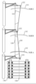
Referring to fig. 1, a contact suspension for supplying power to rail transit vehicles is arranged above a line 140, and the contact suspension comprises a contact line 120 and a catenary 130, wherein the catenary 130 provides tension for the contact line 120 through a dropper 131, so that the contact line 120 between two contact net supports keeps good straightness, and the contact suspension is carried by the contact net supports.
The pantograph 110 is positioned at the top of the train, the electric power is obtained from the contact line 120 through elastic friction between the pantograph 110 and the contact line 120, in order to evenly distribute the friction between the contact line 120 and the pantograph 110 in the process of power receiving, the contact line is arranged in a zigzag shape in engineering, and the contact part between the contact line arranged in the zigzag shape and a pantograph plate of the pantograph is constantly changed in the process of moving the pantograph along the line, so that continuous friction on the same part of the pantograph plate is avoided, the local temperature rise is reduced, and the service life of the pantograph is prolonged.
The zigzag arrangement of the contact lines is realized by adjusting the positions of positioning points at the positions of the wrists, and reverse positioning is adopted at the positioning points 121 and 123, namely the positioning points are arranged in the direction far away from the support column, so that the distance between the positioning points and the expenditure is greater than the distance between the central line of the line and the support column; the positioning point 122 adopts positive positioning, that is, the positioning point is arranged in the direction close to the pillar, so that the distance between the positioning point and the pillar is less than the distance between the line central line and the pillar; the positions of the positioning points 121, 122 and 123 determine the zigzag shape of the contact wire, i.e. the pulling value of the contact wire.
When the pantograph 110 moves from the position a to the position C through the position a, the position of the contact point between the contact line 120 and the pantograph 110 changes, and friction of the contact line against the pantograph pan is dispersed.
In a straight line section, the line center line 150 and the pantograph center line are in the same vertical plane, and in a curved line section, the line center line 150 and the pantograph center line are not in the same vertical plane.
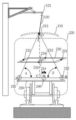
The measurement of the position of the contact line is based on the measurement of a triangular relation, as shown in fig. 2, the length of the side AB in three sides of the triangle OAB is known, the angle values of the angle theta (theta, namely the angle OAB shown in fig. 2) and the angle beta (beta, namely the angle OBA shown in fig. 2) can be obtained by photogrammetry, under the condition that one side length AB, the angle theta and the angle beta are known, the height from the top O to the bottom AB of the triangle OAB can be obtained, the sum of the height and the distance from the bottom AB to the rail plane is the height from the measured point O on the contact line to the rail plane, and if the point O is the positioning point on the contact line, the height is the lead height.
The invention adopts a virtual pantograph method for measuring the position of a contact line relative to the central line of a pantograph, and particularly, as shown in fig. 2, supposing that a pantograph exists near a measured point of a catenary, the actual position and posture of the pantograph 110 are determined by a rail plane where measurement is carried out and the dimension of a virtual train carriage 220 at the measurement position; specifically, the actual position of the pantograph 110 may be calculated from the inclination of the rail plane measured in the field, the height of the virtual railcar 220, the line center line position, and the actual height of the pantograph 110 on the railcar.
In the virtual pantograph method, the bottom edge AB of a triangle OAB is parallel to a rail plane, the longitudinal central line or the longitudinal central plane of a carriage is perpendicular to the rail plane, the central line of a pantograph is superposed with the central line or the central plane of the carriage, after the position C of the projection point of a measured point O of a catenary on the AB is calculated through a triangular relation, the point C is moved to the point C' on a pantograph of the virtual pantograph along a straight line parallel to the central line or the central plane of the carriage, and the point C is the position of the measured point of the catenary on the virtual pantograph;
further, using the distance values from different points C' on the contact line to the center line of the virtual pantograph pan, the offset of the contact line on the virtual pantograph pan per unit distance can be obtained, and using this offset, an estimated value of the pullout value of the contact line can be obtained.
Example of a first embodiment of a method for measuring a catenary
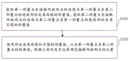
Referring to fig. 3, an embodiment of a method for measuring a catenary provided by the present invention includes the following steps:
step S310, obtaining a measured value of an included angle theta between a connecting line from a first measuring point to a measured point of a contact network and a connecting line from the first measuring point to a second measuring point, and obtaining a measured value of an included angle beta between a connecting line from the second measuring point to the measured point of the contact network and a connecting line from the second measuring point to the first measuring point;
step S320, determining the position of a measured point of the overhead line system according to triangular relation calculation by using the measured values of the theta and beta included angles and the distance value from the first measuring point to the second measuring point;
the first measuring point and the second measuring point are two points with known distance;
the contact net measured point comprises at least one of a contact line measured point, a catenary measured point, a locator measured point and a dropper measured point;
the triangle relation operation is based on a triangle which is determined by the first measuring point, the second measuring point and the measured point of the overhead line system together, the plane of the triangle is perpendicular to the rail plane and perpendicular to the line central line or keeps a known included angle with the line central line, the bottom side of the triangle is a connecting line between the first measuring point and the second measuring point, and the connecting line is parallel to the rail plane or keeps a known included angle with the rail plane.
In particular, the rail plane is the plane defined by the upper surfaces of the two running rails itself or a plane that is in parallel relationship with the plane defined by the upper surfaces of the two running rails.
Preferably, the plane of the triangle is perpendicular to the line center line.
Preferably, a connecting line between the first measuring point and the second measuring point is parallel to a plane corresponding to the rail plane.
Specifically, the first measuring point and the second measuring point are two points moving along with the contact net measuring table surface;
an attitude sensor is arranged on the measuring table top and comprises at least one of a horizontal measuring instrument, an acceleration sensor and a gyroscope;
the attitude sensor is used for sensing at least one of the inclination angle of the contact net measuring table top, the horizontal offset experienced by the contact net measuring table top and the horizontal offset experienced by the contact net measuring table top.
Specifically, the contact net measuring table top inclination angle comprises at least one of an inclination angle along the direction of a line center line and an inclination angle in a plane perpendicular to the line center line.
Further, the height difference h between the two running rails is determined by using the contact net to measure the inclination angle of the table top in the plane vertical to the line center line;
further, the height difference h is used for determining the offset of the virtual pantograph central line and the line central line and determining the position or the adjustment amount of the positioning point of the contact line.
The method of the present embodiment, wherein,
the method for obtaining the measured value of the included angle theta between the connecting line from the first measuring point to the measured point of the overhead line system and the connecting line from the first measuring point to the second measuring point and obtaining the measured value of the included angle beta between the connecting line from the second measuring point to the measured point of the overhead line system and the connecting line from the second measuring point to the first measuring point comprises the following steps:
the method comprises the steps of measuring sunlight irradiation, namely determining a measured point of a contact net by using an optical imaging sensor positioned at a first measuring point, an optical measurement control point positioned in a field of view of the optical imaging sensor and reflection of sunlight by the contact net, determining a measured value of an included angle theta corresponding to the measured point of the contact net by using the optical measurement control point, determining the measured point of the contact net by using an optical imaging sensor positioned at a second measuring point, the optical measurement control point positioned in the field of view of the optical imaging sensor and the reflection of sunlight by the contact net, and determining a measured value of an included angle beta corresponding to the measured point of the contact net by using the optical measurement control point; and/or
And a laser irradiation measuring step, namely determining a measured point of the overhead line system by using an optical imaging sensor positioned at a first measuring point and reflection of the overhead line system on the irradiated laser, determining a measured value of an included angle theta corresponding to the measured point of the overhead line system by using an optical measurement control point, determining the measured point of the overhead line system by using the optical imaging sensor positioned at a second measuring point and reflection of the overhead line system on the laser, and determining a measured value of an included angle beta corresponding to the measured point of the overhead line system by using the optical measurement control point.
Specifically, referring to fig. 2, the laser beam is a linear laser beam which is irradiated to the overhead line from a light source 240 on a measurement table 250 arranged on a track, and a cross section along the length direction of the linear beam and passing through a thickness bisection plane of the linear beam is perpendicular to the central line of the line or perpendicular to the longitudinal direction of the measurement table.
Specifically, the in-line beam thickness bisecting plane is a plane defined by a set of center lines of a cross section of the in-line beam perpendicular to the beam visual axis, or a plane along a middle line of the in-line beam length direction and including the beam visual axis.
Specifically, the measuring table top is a platform for bearing an optical imaging sensor, a laser and an optical measuring control point, or a platform for bearing the optical imaging sensor and the optical measuring control point, and the table top or the measuring surface of the platform is parallel to the rail plane; the longitudinal direction of the measuring table top is consistent with the extending direction of the rail or the included angle between the longitudinal direction of the measuring table top and the extending direction of the rail is less than 30 degrees.
Specifically, the sunlight irradiation measuring step is used for acquiring a measured value of an included angle theta or beta by utilizing an image of sunlight reflected by the overhead line system on the optical imaging sensor, and the measuring step is suitable for measurement under the condition of sunlight irradiation.
In particular, the laser irradiation measurement step is used for acquiring the measurement value of the theta or beta angle by utilizing the image of the laser reflected by the overhead line system on the optical imaging sensor, and the measurement step is suitable for carrying out measurement under the condition of laser beam irradiation.
Specifically, the reflection of the illuminating laser by the overhead line system comprises the reflection of a linear beam by the overhead line system, wherein the section of the linear beam along the direction of a linear line and passing through the thickness bisector of the beam is coplanar with a triangle jointly determined by the first measuring point, the second measuring point and the measured point of the overhead line system, so that the section of the linear beam is perpendicular to the plane of the rail and perpendicular to the central line of the line or keeps a known included angle with the central line of the line.
Specifically, the linear beam is a linear laser beam having the strongest power density at the middle of the linear beam and gradually reduced power density from the middle of the linear beam to both sides of the linear width or both ends of the linear length.
Specifically, the optical measurement control point located in the field of view of the optical imaging sensor comprises at least one of the following configurations corresponding to the sunshine irradiation measuring step:
in the first configuration, the optical measurement control points are disposed on a rectangular frame as an optical measurement mark, and as shown in fig. 2, the rectangular frame 230 is located in the field of view of the optical imaging sensor, the plane on which the four sides of the rectangular frame are located is parallel to the rail plane, the two long sides of the rectangular frame are perpendicular to the line center line, and the manner of disposing the optical measurement control points on the rectangular frame includes:
taking central points 233 and 234 of two long sides and central points 231 and 232 of two short sides of the rectangular frame as optical measurement control points, taking a plane which passes through a connecting line of the central points 231 and 232 of the two short sides and is perpendicular to a plane where the rectangular frame is located as a measurement surface of a measured point of the overhead line system, arranging a visual axis of the optical imaging sensor in the measurement surface, and determining the position of the measured point of the overhead line system by the measurement surface; further, a connecting line between the center points 233 and 234 of the two long sides is used as a scale mark for angle measurement; further, the coordinates of the center point of the connecting line between the center points 233 and 234 of the two long sides are taken as reference coordinates for the detection of the positioning error; or
Using four vertexes on the inner side edge of a rectangular frame as optical measurement control points, enabling a plane where a rectangle formed by the four vertexes on the inner side of the rectangular frame is located to be parallel to a rail plane, enabling a connecting line of middle lines of two short sides of the rectangle formed by the four vertexes to form a bisector of the rectangle in the length direction, enabling a plane which passes through the bisector of the rectangle in the length direction and is perpendicular to the rectangle to be used as a measurement surface of a measured point of a contact net, setting a visual axis of an optical imaging sensor in the measurement surface, and determining the position of the measured point of the contact net through the measurement surface; furthermore, scale marks for angle measurement are arranged on the two long sides of the rectangle, the positions of the scale marks on the two long sides are equal and the scales are the same, and a connecting line between the equal scale marks is parallel to the central line of the line; furthermore, the coordinate of the central point of the connecting line between the equivalent scale marks on the two long edges is used as the reference coordinate for detecting the positioning error;
setting optical measurement control points on two parallel strips serving as optical measurement marks, taking two points on each parallel strip to form a vertex of a quadrangle, wherein the plane of the quadrangle is parallel to the rail plane, two long sides of the quadrangle are perpendicular to the line center line, and setting a contact line measurement surface, setting a visual axis of an optical imaging sensor, setting a scale mark for angle measurement and setting a reference coordinate for positioning error detection according to the step of using four vertices on the inner side edge of a rectangular frame as the optical measurement control points in the first mode;
setting optical measurement control points on four mark shapes serving as optical measurement marks, taking two points on each mark shape to form a vertex of a quadrangle, wherein the plane of the quadrangle is parallel to a rail plane, two long sides of the quadrangle are perpendicular to a line central line, setting a contact line measuring surface, setting a visual axis of an optical imaging sensor, setting scale marks for angle measurement (the scale marks are virtual scales, and the virtual scales derive equidistant virtual scale points by taking coordinates of the two long sides of the quadrangle as references) and setting reference coordinates for positioning error detection according to the step of using the four vertices on the inner side edge of the rectangular frame as the optical measurement control points in the first mode;
wherein the content of the first and second substances,
the measuring surface is used for determining the position of a measured point of the contact network on the contact network, the intersection point of the measuring surface and the contact network is the position of the measured point of the contact network, and the intersection point of the measuring surface and the contact network comprises at least one of the intersection point of a positioning surface of the measured point of the contact network and a contact line of the contact network, the intersection point of a messenger cable of the contact network, the intersection point of a locator of the contact network and a dropper of the contact network.
Specifically, the optical measurement control point located in the field of view of the optical imaging sensor includes at least one of the following configurations corresponding to the laser irradiation measuring step:
in the first configuration, the optical measurement control points are disposed on a rectangular frame as an optical measurement mark, and as shown in fig. 2, the rectangular frame 230 is located in the field of view of the optical imaging sensor, the plane on which the four sides of the rectangular frame are located is parallel to the rail plane, the two long sides of the rectangular frame are perpendicular to the line center line, and the manner of disposing the optical measurement control points on the rectangular frame includes:
taking central points 233 and 234 of two long sides and central points 231 and 232 of two short sides of the rectangular frame as optical measurement control points, taking a plane which passes through a connecting line of the central points 231 and 232 of the two short sides and is perpendicular to a plane where the rectangular frame is located as a measurement plane of a measured point of the overhead line system, arranging a visual axis of an optical imaging sensor in the measurement plane, setting the irradiation direction of the in-line laser beam to enable a beam bisection plane of the in-line laser beam along the in-line length direction to be coplanar with the measurement plane, and determining the position of the measured point of the overhead line system by the measurement plane; further, a connecting line between the center points 233 and 234 of the two long sides is used as a scale mark for angle measurement; further, the coordinates of the center point of the connecting line between the center points 233 and 234 of the two long sides are taken as reference coordinates for the detection of the positioning error; or
Using four vertexes on the inner side edge of a rectangular frame as optical measurement control points, enabling a plane where a rectangle formed by the four vertexes on the inner side of the rectangular frame is located to be parallel to a rail plane, enabling a connecting line of middle lines of two short sides of the rectangle formed by the four vertexes to form a bisector of the rectangle in the length direction, enabling a plane which passes through the bisector of the rectangle in the length direction and is perpendicular to the rectangle to be used as a measurement surface of a measured point of a catenary, enabling a visual axis of an optical imaging sensor to be arranged in the measurement surface, enabling a beam bisector of a linear laser beam to be arranged in the irradiation direction to be coplanar with the measurement surface, and determining the position of the measured point of the catenary through the measurement surface; furthermore, scale marks for angle measurement are arranged on the two long sides of the rectangle, the positions of the scale marks on the two long sides are equal and the scales are the same, and a connecting line between the equal scale marks is parallel to the central line of the line; furthermore, the coordinate of the central point of the connecting line between the equivalent scale marks on the two long edges is used as the reference coordinate for detecting the positioning error;
setting optical measurement control points on two parallel strips serving as optical measurement marks, taking two points on each parallel strip to form a quadrilateral vertex, wherein the plane of the quadrilateral is parallel to a rail plane, two long edges of the quadrilateral are perpendicular to a line central line, and setting a contact line measurement surface, setting a visual axis of an optical imaging sensor, setting a scale mark for angle measurement, setting a reference coordinate for positioning error detection and setting the irradiation direction of a linear laser beam to enable the beam bisection surface of the linear laser beam along the linear length direction to be coplanar with the measurement surface according to the step of using the four vertices on the inner edge of a rectangular frame as the optical measurement control points in the first mode;
specifically, the scale for angle measurement described in this embodiment is determined by an optical measurement control point whose line is in a plane parallel to the track plane and perpendicular to the line center line or at a known angle to the line center line, and further includes: the angle value of an included angle corresponding to the two optical measurement control points with known positions and the known angle between the optical measurement control points and the visual axis of the optical imaging sensor are utilized to calculate the angle corresponding to the unit distance on the straight line passing through the two optical measurement control points with known positions, the straight line is used as an angle measurement scale line, and the theta angle value or the beta angle value of the measured point of the overhead line system is determined according to the intersection point of the straight line passing through the measured point and the measured point of the contact line and the angle measurement scale line.
In the present embodiment, the first and second electrodes are,
the cross section of the linear beam along the direction of a linear line and passing through the thickness bisection plane of the beam, the beam bisection plane along the length direction of the linear beam, the thickness bisection plane of the linear beam and a plane which is along the middle line of the length direction of the linear beam and contains the visual axis of the beam are the same plane.
The method of the present embodiment, wherein,
the determining the position of the measured point of the overhead line system according to the triangle relation operation by using the measured values of the theta and the beta of the included angle and the distance value from the first measuring point to the second measuring point comprises the following steps:
in a first coordinate system, determining a measured value of an included angle theta and a measured value of an included angle beta corresponding to a measured point of a contact network, and calculating the length of an OC corresponding to the measured point of the contact network and the position of an intersection point C by using the tangent relation of a right triangle;
wherein the content of the first and second substances,
the length of the OC is the distance from a measured point of the overhead line system to a connecting line AB of the first measuring point and the second measuring point;
the intersection point C is the intersection point of a perpendicular line OC from a measured point of the overhead contact system to a connecting line AB of the first measuring point and the second measuring point and the connecting line AB of the first measuring point and the second measuring point;
the first coordinate system is a rectangular coordinate system or a polar coordinate system.
Preferably, the first coordinate system in this embodiment is a rectangular coordinate system.
Specifically, the first coordinate system is a coordinate system based on the measurement table, the orientation of the coordinate axes of the coordinate system changes along with the change of the posture of the measurement table, and the origin of the coordinate system moves along with the movement of the measurement table.
Further, when the measuring table moves along the rail, the origin position of the first coordinate system and the orientation of the coordinate axes of the first coordinate system are determined by using a second coordinate system, wherein the second coordinate system is a geodetic coordinate system or a coordinate system defined based on a geodetic horizontal plane;
the geodetic coordinate system is a coordinate system based on a track plane Control Point CPIII (CP: Control Point/Control Plan);
the coordinate system defined based on the geodetic level is a coordinate system having the geodetic level as one plane of the coordinate system and a specific point whose position is unchanged with respect to the track plane control point CPIII as an origin.
Further, in order to determine the coordinates of the measured point of the catenary in the second coordinate system, the coordinates of the measured point of the catenary are subjected to coordinate transformation, and the coordinate values of the measured point of the catenary in the first coordinate system are converted into coordinate values in the second coordinate system.
In the embodiment, in order to convert the coordinate value of the measured point of the contact network in the first coordinate system into the coordinate value in the second coordinate system, the attitude sensor and the position sensor are arranged on the measuring table top;
the attitude sensor comprises at least one of an electronic level, an acceleration sensor and a gyroscope and is used for measuring the longitudinal and transverse inclination angles of the measuring table relative to the ground horizontal plane;
the position sensor is used for measuring the coordinates of a specific point of the measuring table top in the second coordinate system and the displacement of the measuring table top in the geodetic horizontal plane;
and converting the coordinate values of the measured point of the catenary in the first coordinate system into the coordinate values in the second coordinate system by using the longitudinal and transverse inclination angles of the measuring table surface relative to the ground level, the coordinates of a specific point of the measuring table surface in the second coordinate system and the displacement of the measuring table surface in the ground level.
In this embodiment, as a specific implementation manner for determining a measurement value of an included angle theta and a measurement value of an included angle beta corresponding to a measured point of a catenary, the implementation manner includes:
identifying a smaller theta value from the theta values of included angles corresponding to two measured points contained in the primary imaging of the optical imaging sensor to the contact net, and identifying a smaller beta value from the beta values of included angles corresponding to two measured points contained in the primary imaging of the optical imaging sensor to the contact net, wherein one of the two measured points is a measured point on the contact line, and the other one is a measured point on the catenary;
the identified smaller theta value and the identified smaller beta value are used as a measured value of an included angle theta and a measured value of an included angle beta corresponding to a measured point of the contact line;
optionally, the identified larger theta value and larger beta value are used as the measured value of the angle theta and the measured value of the angle beta corresponding to the measured point of the catenary.
In this embodiment, as another specific implementation manner for determining a measured value of an included angle theta and a measured value of an included angle beta corresponding to a measured point of a catenary, the implementation manner includes:
identifying a smaller theta value from the theta values of included angles corresponding to two measured points contained in the primary imaging of the optical imaging sensor to the contact net, and identifying a smaller beta value from the beta values of included angles corresponding to two measured points contained in the primary imaging of the optical imaging sensor to the contact net, wherein one of the two measured points is a measured point on the contact line, and the other one is a measured point on the catenary;
the contact net image acquired by the optical imaging sensor is used for judging whether the crossed image of the contact line and the catenary exists or not,
if not, the identified smaller theta value and the identified smaller beta value are used as the theta included angle measured value and the beta included angle measured value corresponding to the measured point of the contact line; optionally, the identified larger theta value and the identified larger beta value are used as a measured value of an included angle theta and a measured value of an included angle beta corresponding to the measured point of the catenary cable;
if so, using the identified smaller theta value and the identified larger beta value as the measured value of the included angle theta and the measured value of the included angle beta corresponding to the measured point of the contact line, or using the identified larger theta value and the identified smaller beta value as the measured value of the included angle theta and the measured value of the included angle beta corresponding to the measured point of the contact line;
further, at least one of the known trend and height of the contact line and the position of the contact line obtained by previous measurement is used for judging whether the collocation between the measured value of the included angle theta and the measured value of the included angle beta is correct.
In this embodiment, as a specific implementation manner of calculating the length of the OC corresponding to the measured point of the catenary and the position of the intersection point C by using the tangent relation of the right triangle, as shown in fig. 2, the method includes:
a triangle formed by a first measurement point 211 (the point is marked as a in the figure), a second measurement point 212 (the point is marked as B in the figure) and a catenary measured point 213 (the point is marked as O in the figure) is represented as Δ ABO, and three sides of the triangle are OA, OB and AB respectively;
a line segment OC is obtained by drawing a perpendicular line from the vertex O of the triangle to the side AB, and the intersection 214 (the point is marked as C in the figure) of the OC and the side AB divides the side AB into two parts, namely AC and CB;
the theta is an internal angle corresponding to the vertex A of the triangle delta ABO and is also an internal angle corresponding to the vertex A of the right-angled triangle OAC;
the angle beta (beta) is an internal angle corresponding to the vertex B of triangle delta ABO, and is also an internal angle corresponding to the vertex B of right-angled triangle OBC.
According to the definition of the tangent operation of a right triangle, the following relationship exists between the two sides OC and AC of a right triangle OAC:
tan(theta)=OC/AC (1)
in the formula, AC and OC are the side lengths of two right-angle sides of a right-angle triangle OAC respectively, wherein OC and AC are to-be-solved quantities;
according to the definition of tangent operation of the right triangle, the following relationship exists between two sides OC and BC of the right triangle OBC:
tan(beta)=OC/BC (2)
in the formula, BC and OC are respectively the side lengths of two right-angle sides of a right-angle triangle OAC, wherein OC and BC are to-be-solved quantities;
the combination relation is as follows:
AC=AB- BC (3)
wherein AB is the bottom edge length of the delta ABO, AB is a known quantity, and AC and BC are quantities to be solved;
by using the relational expressions (1), (2) and (3), AC, BC and OC can be solved;
then, the distance (the distance is the length of OC) from the measured point of the catenary (the point is marked as O in the figure) to the connecting line AB (the connecting line is the side AB of the triangle OAB) between the first measuring point (the point is marked as a in the figure) and the second measuring point (the point is marked as B in the figure) is calculated;
then, the position of the intersection (the intersection is denoted by C in the drawing) of the perpendicular (the perpendicular is OC) from the measured point of the catenary (the point is denoted by O in the drawing) to the line AB (the line AB is the side AB of the triangle OAB) connecting the first measurement point and the second measurement point (the point is denoted by B in the drawing) and the line AB (the line AB is the side AB of the triangle OAB) connecting the first measurement point and the second measurement point (the intersection is denoted by C in the drawing) is calculated (the position refers to the distance AC from the intersection C to the first measurement point a or the distance CB to the second measurement point B).
The method of the present embodiment, wherein,
the determining a measured value of an included angle theta and a measured value of an included angle beta corresponding to a measured point of the catenary, and calculating the length of an OC corresponding to the measured point of the catenary and the position of an intersection point C by using a tangent relation of a right triangle, further comprises:
determining the height measurement value of the contact line by using the distance OC from the measured point of the contact line to the connecting line AB of the first measurement point and the second measurement point and the distance from the connecting line AB of the first measurement point and the second measurement point to the rail plane;
and determining the distance of the measured point of the overhead line system relative to the central line of a virtual pantograph by using the position of the intersection point, wherein the virtual pantograph is used for simulating the position of the vehicle-mounted pantograph above the track line.
The virtual pantograph central line is a straight line or a line segment which passes through the central point of the length of the pantograph pan and is vertical to the length direction of the pantograph pan;
the virtual pantograph is used for simulating the position of the vehicle-mounted pantograph above a track line, and means that the height and the inclination angle of the virtual pantograph are consistent with those of the pantograph on a train passing through the line at the spatial position corresponding to the measured point of the overhead line system; or
Errors between the height and the inclination angle of the virtual pantograph and the height and the inclination angle of the pantograph on the train passing through the line can be ignored; or
The inclination angle of the virtual pantograph is consistent with the inclination angle of the pantograph on the train passing through the line, and the absolute value of the difference between the height of the virtual pantograph and the height of the pantograph on the train passing through the line is less than 0.3 m; or
The inclination angle of the virtual pantograph is consistent with the inclination angle of the pantograph on the train passing through the line, and the absolute value of the difference between the height of the virtual pantograph and the actual height of the contact line is less than 0.3 meter.
Specifically, the determining a height measurement value of the contact line by using the distance from the measured point of the contact line to the connecting line of the first measuring point and the second measuring point and the distance from the connecting line of the first measuring point and the second measuring point to the plane of the rail comprises:
and adding the distance from the measured point of the contact net to the connecting line of the first measuring point and the second measuring point and the distance from the connecting line of the first measuring point and the second measuring point to the plane of the contact net to calculate, and taking the sum as the height measured value of the contact line or the height of the contact line.
Specifically, the determining the distance between the measured point of the catenary and the center line of a virtual pantograph used for simulating the position of an on-vehicle pantograph above the track line by using the position of the intersection point comprises the following steps:
referring to fig. 2, the method for determining the position of the measured point of the catenary on the actual pantograph by using the virtual pantograph method includes:
assuming that there is a pantograph 110 near the catenary point being measured, the actual position and attitude of the pantograph 110 is determined by the rail plane where the measurement is made and the dimensions of the virtual railcar 220 at the measurement; specifically, the actual position of the pantograph 110 may be calculated from the inclination of the rail plane measured on site, the height of the virtual railcar 220, and the actual height of the pantograph 110 on the railcar.
In the method for simulating the position of the vehicle-mounted pantograph above a track line by the virtual pantograph, the base line AB of a triangle OAB is parallel to a rail plane, the central line or the central plane of a carriage is perpendicular to the rail plane, the central line of the pantograph is superposed with the central line or the central plane of the carriage, after the position C of a projection point of a measured point O of a catenary on the base line AB is calculated, the point C is moved to a point C 'on a pantograph of the virtual pantograph along a straight line parallel to the central line or the central plane of the carriage, and the point C' is the position of the measured point of the catenary on the virtual pantograph;
further, determining the offset rate of the contact line in unit distance by using the distance values from different points C' on the contact line to the center line of the virtual pantograph pan, wherein the offset rate of the contact line in unit distance is the offset of the contact line in unit distance on the virtual pantograph pan;
and obtaining an estimated value of the pulling value of the contact line by using the deviation rate of the contact line in unit distance and the distance between the position control points of two adjacent contact lines.
Further, whether or not the pullout value of the contact line is within the design range is judged using the rate of displacement of the contact line per unit distance, or using an estimated value of the pullout value of the contact line.
The method of this embodiment further includes at least one of a positioning error detection method and a laser beam irradiation error detection method, wherein,
the positioning error detection method comprises the following steps:
the method comprises the steps of obtaining a measured value of an included angle theta between a connecting line from a first measuring point to a detection reference point with known position coordinates and a connecting line from the first measuring point to a second measuring point, and obtaining a measured value of an included angle beta between a connecting line from the second measuring point to the detection reference point and a connecting line from the second measuring point to the first measuring point;
determining the measurement value of the position coordinate of the detection reference point according to the triangle relation operation by using the measurement values of the theta and the beta of the included angle and the distance value from the first measurement point to the second measurement point;
calculating a distance error between a measured value of the position coordinates of the detection reference points and a known value of the position coordinates of the detection reference points;
if the distance error is greater than or equal to a distance error threshold, judging the distance error to be overproof, and if the distance error is less than the distance error threshold, judging the distance error not to be overproof;
wherein the detection reference point comprises an optical measurement control point with known position coordinates or a derived point comprising the optical measurement control point;
the laser beam irradiation error detection method includes the steps of:
receiving an irradiation spot image of the in-line laser beam emitted from the light source 240 included in the laser irradiation sub-module 412 on the optical measurement mark using the optical imaging sensor;
calculating the distance from the central line of the linear laser beam along the linear length direction to a first measurement control point and a second measurement control point on the optical measurement mark;
judging whether the distances are all smaller than a preset irradiation error threshold, if so, judging the irradiation error of the laser beam not to exceed the standard, and if not, judging the irradiation error of the laser beam to exceed the standard;
or
An optical imaging sensor is used for receiving an irradiation spot image of a linear laser beam on a measured point of a contact network;
determining the position of the measured point of the overhead line system by using the optical imaging sensor and the measuring surface of the measured point of the overhead line system determined by the optical measurement control point;
calculating the distance between the position of the measured point of the overhead line system determined by the measuring surface and the position of the irradiation light spot image;
and judging whether the distance is smaller than a preset superposition error threshold of the light spot and the measuring surface, if so, judging that the irradiation error of the laser beam does not exceed the standard, and if not, judging that at least one of the irradiation of the laser beam and the measuring surface of the measured point of the contact network is abnormal.
Specifically, the derived point 235 of the optical measurement control point is a point whose position coordinates derived based on the position of the optical measurement control point are known;
a specific method of determining the derivation point of an optical measurement control point, as shown in fig. 2, comprises:
a derivation point 235 using an intersection of a line between the optical measurement control points 231 and 232 on the optical measurement flag 230 and a line between the optical measurement control points 233 and 234 as an optical measurement control point;
the coordinates of the derived point 235 of the optical measurement control point are determined using the coordinates of the optical measurement control points 231, 232, 233, and 234.
Specifically, the irradiation spot of the in-line laser beam on the optical measurement mark is generated by irradiating the laser source 240 mounted on the measurement table 250 onto the optical measurement mark 230, in this embodiment, the in-line length direction of the in-line laser beam is designed to be perpendicular to the line center line, in performing the laser beam irradiation error detection, a first part of the in-line laser beam is irradiated on the measurement control point 231 or in the vicinity of the measurement control point 231 to form a first spot on the optical measurement mark 230, and a second part of the in-line laser beam is irradiated on the measurement control point 231 or in the vicinity of the measurement control point 231 to form a second spot on the optical measurement mark 230.
Specifically, the calculating of the distance from the center line of the in-line laser beam in the length direction of the in-line laser beam to the first measurement control point and the second measurement control point on the optical measurement mark includes:
calculating the distance from the center line of the linear laser beam along the linear length direction to the first measurement control point 231 and the second measurement control point 232 on the optical measurement mark; or
The distance of the centroid of said first spot of the in-line laser beam to the first measurement control point 231 and the distance of the centroid of the second spot to the second measurement control point 232 are calculated.
The optical measurement control point is a specific point characterized by at least one of a planar optical measurement mark, a linear optical measurement mark and a cylindrical optical measurement mark;
preferably, the optical measurement control point has a specific shape.
Specifically, the position coordinates and the shape dimension of the optical measurement control points are known.
Specifically, the distance error threshold is a real number with a value less than 5, and the unit is millimeter;
specifically, the illumination error threshold is a real number with a value less than 2, and the unit is millimeter;
specifically, the measurement plane coincidence error threshold is a real number smaller than 1, and the unit is millimeter.
The method provided by this embodiment further includes a position indication method, which specifically includes:
indicating a target position to which the contact line needs to be adjusted using a spatial position indicator located above the track; or
And displaying at least one of the current position, the target position, the positioning point adjustment amount and the hanger adjustment amount of the contact line using a display.
Wherein the target position is a design position of the contact line, or a spatial position where the contact line should be located if a designed pull-out value and a designed lead-up value are satisfied.
Specifically, the displaying the current position and the target position of the contact line by using the display comprises:
and displaying the current position and the target position of the contact line obtained by measurement on a display in a graphical mode.
The target position is a design position of the contact line, or the position of a measured point of the contact line determined by using a design offset rate of the contact line on a unit distance and a distance from the measured point of the contact line to a positioning point;
the design deviation rate of the contact line in unit distance is calculated by using the designed contact line pulling value and the distance between adjacent positioning points.
Specifically, the display positioning point adjustment amount and the hanger adjustment amount include at least one of the following adjustment amounts:
adjusting the horizontal position of the positioning point;
the vertical position adjustment amount of a positioning point;
the angle adjustment of the positioner; and
the length adjustment of the hanger.
Specifically, the hanger length adjustment amount is determined using the deviation amount of the measured position of one or more measured points of the contact line from the corresponding target position.
Specifically, the target position to which the contact line needs to be adjusted is indicated by using a spatial position indicator located above the track, and the method comprises the following steps:
and using an electromechanical indicator or a photoelectric indicator as a space position indicator to mark the actual space position of the target position to which the contact line needs to be adjusted.
In this embodiment, as an implementation manner of using the electromechanical indicator to mark an actual spatial position of a target position to which a contact line needs to be adjusted, the implementation manner includes:
the height and the transverse position of a position pointer contained in the electromechanical indicator are adjusted, so that the top end of the position pointer coincides with a target position to which the contact line needs to be adjusted.
In this embodiment, as an implementation manner of using the photoelectric indicator to mark an actual spatial position of a target position to which a contact line needs to be adjusted, the implementation manner includes:
and using a position indication bow consistent with the height, position and posture of the vehicle-mounted pantograph as a photoelectric indicator to mark the actual space position of the target position to which the contact line needs to be adjusted, wherein the position indication bow is provided with a photoelectric indication component which marks the actual space position of the target position to which the contact line needs to be adjusted in the form of an optical symbol.
Specifically, the shape of the upper surface of the electromechanical indicator or the photoelectric indicator is the same as the shape and the size of the pantograph pan of the actual pantograph.
In particular, the electromechanical or photoelectric indicator comprises a pressure sensor for measuring the pressure from the contact line.
At least one of the height, inclination, azimuth and center position of the spatial position indicator may be automatically adjusted, wherein,
the specific method for adjusting the height and the inclination angle of the spatial position indicator comprises the following steps:
measuring the distances from the two ends of the space position indicator to the reference table top of the measuring table top by using a laser ranging module, adjusting the height of the space position indicator to ensure that the distances from the two ends of the space position indicator to the reference table top of the measuring table top are the same, and ensuring that the height of the space position indicator is at a preset height value;
the specific method for adjusting the azimuth angle of the spatial position indicator comprises the following steps:
observing an included angle between a azimuth line on the space position indicator and an azimuth reference line on a reference table top of the measuring table top by using an optical imaging sensor, and adjusting the azimuth angle of the space position indicator to enable the azimuth line and the azimuth reference line to be in an overlapped state or enable the included angle to be smaller than a preset included angle threshold;
the specific method for adjusting the center position of the spatial position indicator comprises the following steps:
observing the deviation between an aiming line on a space position indicator and a cross line intersection point or a target ring central point on a reference table top of a measuring table top by using an optical imaging sensor, and adjusting the position of the space position indicator to enable the aiming line and the cross line intersection point or the target ring central point to be in an overlapped state or enable the distance between the aiming line and the cross line intersection point or the target ring central point to be smaller than a preset distance threshold; or
Observing the deviation between the irradiation point of the linear laser beam emitted by the space position indicator on the reference table top of the measuring table top and the intersection point of the cross line or the central point of the target ring on the reference table top by using an optical imaging sensor, and adjusting the position of the space position indicator to enable the irradiation point and the intersection point of the cross line or the central point of the target ring to be in an overlapped state or enable the distance between the irradiation point and the intersection point of the cross line or the central point of the target ring to be smaller than a.
Specifically, the spacing threshold is a real number less than 5 in millimeters.
Specifically, the included angle threshold is a real number smaller than 1, and the unit is degree.
In this embodiment, the height of the spatial position indicator is adjusted to make the distances from the two ends of the spatial position indicator to the reference table of the measurement table be the same, and the height of the spatial position indicator is at a predetermined height value, so as to achieve the parallelism of the spatial position indicator and the reference table of the measurement table, and to make the spatial position indicator reach a predetermined value from the reference table.
The method of the present embodiment, wherein,
the laser irradiation measuring step further comprises a laser protection method, and specifically comprises the following steps:
the vicinity of the laser beam is detected using an ultrasonic probe beam, and irradiation of the laser beam is interrupted when the presence of the object is detected using the ultrasonic probe beam.
Specifically, the detecting the adjacent region of the laser beam by using the ultrasonic detection beam includes:
covering the adjacent area of the in-line laser beam by using an ultrasonic beam with a beam angle larger than the angle range of the in-line laser beam; or
One or more ultrasonic beams are used to cover the vicinity of the in-line laser beam.
Specifically, the interrupting of the irradiation of the laser beam includes at least one of powering off a line laser beam light source, shielding the line laser beam, and changing an irradiation direction of the line laser beam.
Specifically, the detecting of the presence of the object using the ultrasonic detection beam includes detecting the presence of a head of a person in a detection range of the ultrasonic detection beam and detecting the presence of a moving object in the detection range of the ultrasonic detection beam.
Second embodiment, an example of a contact net measuring device
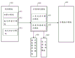
Referring to fig. 4, an embodiment of a measuring device for a catenary provided by the present invention includes:
an angle measurement module 410 and a position determination module 420; wherein the content of the first and second substances,
the angle measurement module 410 is used for obtaining a measured value of an included angle theta between a connecting line from a first measuring point to a measured point of a contact network and a connecting line from the first measuring point to a second measuring point, and obtaining a measured value of an included angle beta between a connecting line from the second measuring point to the measured point of the contact network and a connecting line from the second measuring point to the first measuring point, and comprises a measuring submodule 411, wherein the measuring submodule 411 comprises a first angle measurement submodule and a second angle measurement submodule, the first angle measurement submodule is used for measuring the included angle theta, and the second angle measurement submodule is used for measuring the included angle beta;
the position determining module 420 is configured to determine the position of a measured point of the catenary according to a triangular relationship operation by using the measurement values of the theta and the beta of the included angle and the distance value from the first measurement point to the second measurement point, and includes a triangular relationship calculating submodule and a position parameter determining submodule;
the first measuring point and the second measuring point are two points with known distance;
the contact net measured point comprises at least one of a contact line measured point, a catenary measured point, a locator measured point and a dropper measured point;
the triangle relation operation is based on a triangle which is determined by the first measuring point, the second measuring point and the measured point of the overhead line system together, the plane of the triangle is perpendicular to the rail plane and perpendicular to the line central line or keeps a known included angle with the line central line, the bottom side of the triangle is a connecting line between the first measuring point and the second measuring point, and the connecting line is parallel to the rail plane or keeps a known included angle with the rail plane.
In particular, the rail plane is the plane defined by the upper surfaces of the two running rails itself or a plane that is in parallel relationship with the plane defined by the upper surfaces of the two running rails.
Preferably, the plane of the triangle is perpendicular to the line center line.
Preferably, a connecting line between the first measuring point and the second measuring point is parallel to a plane corresponding to the rail plane.
Specifically, the first measuring point and the second measuring point are two points moving along with the contact net measuring table surface;
an attitude sensor is arranged on the measuring table top and comprises at least one of a horizontal measuring instrument, an acceleration sensor and a gyroscope;
the attitude sensor is used for sensing at least one of the inclination angle of the contact net measuring table top, the horizontal offset experienced by the contact net measuring table top and the horizontal offset experienced by the contact net measuring table top.
Specifically, the contact net measuring table top inclination angle comprises at least one of an inclination angle along the direction of a line center line and an inclination angle in a plane perpendicular to the line center line.
Further, the height difference h between the two running rails is determined by using the contact net to measure the inclination angle of the table top in the plane vertical to the line center line;
further, the height difference h is used for determining the offset of the virtual pantograph central line and the line central line and determining the position or the adjustment amount of the positioning point of the contact line.
The present embodiment provides an apparatus, wherein,
the operation executed by the angle measurement module 410 to obtain a measured value of an included angle theta between a connecting line from a first measurement point to a measured point of a catenary and a connecting line from the first measurement point to a second measurement point and obtain a measured value of an included angle beta between a connecting line from the second measurement point to the measured point of the catenary and a connecting line from the second measurement point to the first measurement point specifically includes the following operation steps:
the method comprises the steps of measuring sunlight irradiation, namely determining a measured point of a contact net by using an optical imaging sensor positioned at a first measuring point, an optical measurement control point positioned in a field of view of the optical imaging sensor and reflection of sunlight by the contact net, determining a measured value of an included angle theta corresponding to the measured point of the contact net by using the optical measurement control point, determining the measured point of the contact net by using an optical imaging sensor positioned at a second measuring point, the optical measurement control point positioned in the field of view of the optical imaging sensor and the reflection of sunlight by the contact net, and determining a measured value of an included angle beta corresponding to the measured point of the contact net by using the optical measurement control point; and/or
And a laser irradiation measuring step, namely determining a measured point of the overhead line system by using an optical imaging sensor positioned at a first measuring point and reflection of the overhead line system on the irradiated laser, determining a measured value of an included angle theta corresponding to the measured point of the overhead line system by using an optical measurement control point, determining the measured point of the overhead line system by using the optical imaging sensor positioned at a second measuring point and reflection of the overhead line system on the laser, and determining a measured value of an included angle beta corresponding to the measured point of the overhead line system by using the optical measurement control point.
Specifically, referring to fig. 2, the laser beam is a linear laser beam which is irradiated to the overhead line from a light source 240 on a measurement table 250 arranged on a track, and a cross section along the length direction of the linear beam and passing through a thickness bisection plane of the linear beam is perpendicular to the central line of the line or perpendicular to the longitudinal direction of the measurement table.
Specifically, the in-line beam thickness bisecting plane is a plane defined by a set of center lines of a cross section of the in-line beam perpendicular to the beam visual axis, or a plane along a middle line of the in-line beam length direction and including the beam visual axis.
Specifically, the measuring table top is a platform for bearing an optical imaging sensor, a laser and an optical measuring control point, or a platform for bearing the optical imaging sensor and the optical measuring control point, and the table top or the measuring surface of the platform is parallel to the rail plane; the longitudinal direction of the measuring table top is consistent with the extending direction of the rail or the included angle between the longitudinal direction of the measuring table top and the extending direction of the rail is less than 30 degrees.
Specifically, the sunlight irradiation measuring step is used for acquiring a measured value of an included angle theta or beta by utilizing an image of sunlight reflected by the overhead line system on the optical imaging sensor, and the measuring step is suitable for measurement under the condition of sunlight irradiation.
In particular, the laser irradiation measurement step is used for acquiring the measurement value of the theta or beta angle by utilizing the image of the laser reflected by the overhead line system on the optical imaging sensor, and the measurement step is suitable for carrying out measurement under the condition of laser beam irradiation.
Specifically, the reflection of the illuminating laser by the overhead line system comprises the reflection of a linear beam by the overhead line system, wherein the section of the linear beam along the direction of a linear line and passing through the thickness bisector of the beam is coplanar with a triangle jointly determined by the first measuring point, the second measuring point and the measured point of the overhead line system, so that the section of the linear beam is perpendicular to the plane of the rail and perpendicular to the central line of the line or keeps a known included angle with the central line of the line.
Specifically, the linear beam is a linear laser beam having the strongest power density at the middle of the linear beam and gradually reduced power density from the middle of the linear beam to both sides of the linear width or both ends of the linear length.
Specifically, the optical measurement control point located in the field of view of the optical imaging sensor comprises at least one of the following configurations corresponding to the sunshine irradiation measuring step:
in the first configuration, the optical measurement control points are disposed on a rectangular frame as an optical measurement mark, and as shown in fig. 2, the rectangular frame 230 is located in the field of view of the optical imaging sensor, the plane on which the four sides of the rectangular frame are located is parallel to the rail plane, the two long sides of the rectangular frame are perpendicular to the line center line, and the manner of disposing the optical measurement control points on the rectangular frame includes:
taking central points 233 and 234 of two long sides and central points 231 and 232 of two short sides of the rectangular frame as optical measurement control points, taking a plane which passes through a connecting line of the central points 231 and 232 of the two short sides and is perpendicular to a plane where the rectangular frame is located as a measurement surface of a measured point of the overhead line system, arranging a visual axis of the optical imaging sensor in the measurement surface, and determining the position of the measured point of the overhead line system by the measurement surface; further, a connecting line between the center points 233 and 234 of the two long sides is used as a scale mark for angle measurement; further, the coordinates of the center point of the connecting line between the center points 233 and 234 of the two long sides are taken as reference coordinates for the detection of the positioning error; or
Using four vertexes on the inner side edge of a rectangular frame as optical measurement control points, enabling a plane where a rectangle formed by the four vertexes on the inner side of the rectangular frame is located to be parallel to a rail plane, enabling a connecting line of middle lines of two short sides of the rectangle formed by the four vertexes to form a bisector of the rectangle in the length direction, enabling a plane which passes through the bisector of the rectangle in the length direction and is perpendicular to the rectangle to be used as a measurement surface of a measured point of a contact net, setting a visual axis of an optical imaging sensor in the measurement surface, and determining the position of the measured point of the contact net through the measurement surface; furthermore, scale marks for angle measurement are arranged on the two long sides of the rectangle, the positions of the scale marks on the two long sides are equal and the scales are the same, and a connecting line between the equal scale marks is parallel to the central line of the line; furthermore, the coordinate of the central point of the connecting line between the equivalent scale marks on the two long edges is used as the reference coordinate for detecting the positioning error;
setting optical measurement control points on two parallel strips serving as optical measurement marks, taking two points on each parallel strip to form a vertex of a quadrangle, wherein the plane of the quadrangle is parallel to the rail plane, two long sides of the quadrangle are perpendicular to the line center line, and setting a contact line measurement surface, setting a visual axis of an optical imaging sensor, setting a scale mark for angle measurement and setting a reference coordinate for positioning error detection according to the step of using four vertices on the inner side edge of a rectangular frame as the optical measurement control points in the first mode;
setting optical measurement control points on four mark shapes serving as optical measurement marks, taking two points on each mark shape to form a vertex of a quadrangle, wherein the plane of the quadrangle is parallel to a rail plane, two long sides of the quadrangle are perpendicular to a line central line, setting a contact line measuring surface, setting a visual axis of an optical imaging sensor, setting scale marks for angle measurement (the scale marks are virtual scales, and the virtual scales derive equidistant virtual scale points by taking coordinates of the two long sides of the quadrangle as references) and setting reference coordinates for positioning error detection according to the step of using the four vertices on the inner side edge of the rectangular frame as the optical measurement control points in the first mode;
wherein the content of the first and second substances,
the measuring surface is used for determining the position of a measured point of the contact network on the contact network, the intersection point of the measuring surface and the contact network is the position of the measured point of the contact network, and the intersection point of the measuring surface and the contact network comprises at least one of the intersection point of a positioning surface of the measured point of the contact network and a contact line of the contact network, the intersection point of a messenger cable of the contact network, the intersection point of a locator of the contact network and a dropper of the contact network.
Specifically, the optical measurement control point located in the field of view of the optical imaging sensor includes at least one of the following configurations corresponding to the laser irradiation measuring step:
in the first configuration, the optical measurement control points are disposed on a rectangular frame as an optical measurement mark, and as shown in fig. 2, the rectangular frame 230 is located in the field of view of the optical imaging sensor, the plane on which the four sides of the rectangular frame are located is parallel to the rail plane, the two long sides of the rectangular frame are perpendicular to the line center line, and the manner of disposing the optical measurement control points on the rectangular frame includes:
taking central points 233 and 234 of two long sides and central points 231 and 232 of two short sides of the rectangular frame as optical measurement control points, taking a plane which passes through a connecting line of the central points 231 and 232 of the two short sides and is perpendicular to a plane where the rectangular frame is located as a measurement plane of a measured point of the overhead line system, arranging a visual axis of an optical imaging sensor in the measurement plane, setting the irradiation direction of the in-line laser beam to enable a beam bisection plane of the in-line laser beam along the in-line length direction to be coplanar with the measurement plane, and determining the position of the measured point of the overhead line system by the measurement plane; further, a connecting line between the center points 233 and 234 of the two long sides is used as a scale mark for angle measurement; further, the coordinates of the center point of the connecting line between the center points 233 and 234 of the two long sides are taken as reference coordinates for the detection of the positioning error; or
Using four vertexes on the inner side edge of a rectangular frame as optical measurement control points, enabling a plane where a rectangle formed by the four vertexes on the inner side of the rectangular frame is located to be parallel to a rail plane, enabling a connecting line of middle lines of two short sides of the rectangle formed by the four vertexes to form a bisector of the rectangle in the length direction, enabling a plane which passes through the bisector of the rectangle in the length direction and is perpendicular to the rectangle to be used as a measurement surface of a measured point of a catenary, enabling a visual axis of an optical imaging sensor to be arranged in the measurement surface, enabling a beam bisector of a linear laser beam to be arranged in the irradiation direction to be coplanar with the measurement surface, and determining the position of the measured point of the catenary through the measurement surface; furthermore, scale marks for angle measurement are arranged on the two long sides of the rectangle, the positions of the scale marks on the two long sides are equal and the scales are the same, and a connecting line between the equal scale marks is parallel to the central line of the line; furthermore, the coordinate of the central point of the connecting line between the equivalent scale marks on the two long edges is used as the reference coordinate for detecting the positioning error;
setting optical measurement control points on two parallel strips serving as optical measurement marks, taking two points on each parallel strip to form a quadrilateral vertex, wherein the plane of the quadrilateral is parallel to a rail plane, two long edges of the quadrilateral are perpendicular to a line central line, and setting a contact line measurement surface, setting a visual axis of an optical imaging sensor, setting a scale mark for angle measurement, setting a reference coordinate for positioning error detection and setting the irradiation direction of a linear laser beam to enable the beam bisection surface of the linear laser beam along the linear length direction to be coplanar with the measurement surface according to the step of using the four vertices on the inner edge of a rectangular frame as the optical measurement control points in the first mode;
specifically, the scale for angle measurement described in this embodiment is determined by an optical measurement control point whose line is in a plane parallel to the track plane and perpendicular to the line center line or at a known angle to the line center line, and further includes: the angle value of an included angle corresponding to the two optical measurement control points with known positions and the known angle between the optical measurement control points and the visual axis of the optical imaging sensor are utilized to calculate the angle corresponding to the unit distance on the straight line passing through the two optical measurement control points with known positions, the straight line is used as an angle measurement scale line, and the theta angle value or the beta angle value of the measured point of the overhead line system is determined according to the intersection point of the straight line passing through the measured point and the measured point of the contact line and the angle measurement scale line.
In the present embodiment, the first and second electrodes are,
the cross section of the linear beam along the direction of a linear line and passing through the thickness bisection plane of the beam, the beam bisection plane along the length direction of the linear beam, the thickness bisection plane of the linear beam and a plane which is along the middle line of the length direction of the linear beam and contains the visual axis of the beam are the same plane.
The present embodiment provides an apparatus, wherein,
the triangulation relation calculation submodule 421 included in the position determination module 420 performs an operation of determining the position of the measured point of the catenary according to triangulation relation calculation using the measured values of the included angles theta and beta and the distance value from the first measurement point to the second measurement point, including the following operation steps:
in a first coordinate system, determining a measured value of an included angle theta and a measured value of an included angle beta corresponding to a measured point of a contact network, and calculating the length of an OC corresponding to the measured point of the contact network and the position of an intersection point C by using the tangent relation of a right triangle;
wherein the content of the first and second substances,
the length of the OC is the distance from a measured point of the overhead line system to a connecting line AB of the first measuring point and the second measuring point;
the intersection point C is the intersection point of a perpendicular line OC from a measured point of the overhead contact system to a connecting line AB of the first measuring point and the second measuring point and the connecting line AB of the first measuring point and the second measuring point;
the first coordinate system is a rectangular coordinate system or a polar coordinate system.
Preferably, the first coordinate system in this embodiment is a rectangular coordinate system.
Specifically, the first coordinate system is a coordinate system based on the measurement table, the orientation of the coordinate axes of the coordinate system changes along with the change of the posture of the measurement table, and the origin of the coordinate system moves along with the movement of the measurement table.
Further, when the measuring table moves along the rail, the origin position of the first coordinate system and the orientation of the coordinate axes of the first coordinate system are determined by using a second coordinate system, wherein the second coordinate system is a geodetic coordinate system or a coordinate system defined based on a geodetic horizontal plane;
the geodetic coordinate system is a coordinate system based on a track plane Control Point CPIII (CP: Control Point/Control Plan);
the coordinate system defined based on the geodetic level is a coordinate system having the geodetic level as one plane of the coordinate system and a specific point whose position is unchanged with respect to the track plane control point CPIII as an origin.
Further, in order to determine the coordinates of the measured point of the catenary in the second coordinate system, the coordinates of the measured point of the catenary are subjected to coordinate transformation, and the coordinate values of the measured point of the catenary in the first coordinate system are converted into coordinate values in the second coordinate system.
In the embodiment, in order to convert the coordinate value of the measured point of the contact network in the first coordinate system into the coordinate value in the second coordinate system, the attitude sensor and the position sensor are arranged on the measuring table top;
the attitude sensor comprises at least one of an electronic level, an acceleration sensor and a gyroscope and is used for measuring the longitudinal and transverse inclination angles of the measuring table relative to the ground horizontal plane;
the position sensor is used for measuring the coordinates of a specific point of the measuring table top in the second coordinate system and the displacement of the measuring table top in the geodetic horizontal plane;
and converting the coordinate values of the measured point of the catenary in the first coordinate system into the coordinate values in the second coordinate system by using the longitudinal and transverse inclination angles of the measuring table surface relative to the ground level, the coordinates of a specific point of the measuring table surface in the second coordinate system and the displacement of the measuring table surface in the ground level.
In this embodiment, as a specific implementation manner for determining a measurement value of an included angle theta and a measurement value of an included angle beta corresponding to a measured point of a catenary, the implementation manner includes:
identifying a smaller theta value from the theta values of included angles corresponding to two measured points contained in the primary imaging of the optical imaging sensor to the contact net, and identifying a smaller beta value from the beta values of included angles corresponding to two measured points contained in the primary imaging of the optical imaging sensor to the contact net, wherein one of the two measured points is a measured point on the contact line, and the other one is a measured point on the catenary;
the identified smaller theta value and the identified smaller beta value are used as a measured value of an included angle theta and a measured value of an included angle beta corresponding to a measured point of the contact line;
optionally, the identified larger theta value and larger beta value are used as the measured value of the angle theta and the measured value of the angle beta corresponding to the measured point of the catenary.
In this embodiment, as another specific implementation manner for determining a measured value of an included angle theta and a measured value of an included angle beta corresponding to a measured point of a catenary, the implementation manner includes:
identifying a smaller theta value from the theta values of included angles corresponding to two measured points contained in the primary imaging of the optical imaging sensor to the contact net, and identifying a smaller beta value from the beta values of included angles corresponding to two measured points contained in the primary imaging of the optical imaging sensor to the contact net, wherein one of the two measured points is a measured point on the contact line, and the other one is a measured point on the catenary;
the contact net image acquired by the optical imaging sensor is used for judging whether the crossed image of the contact line and the catenary exists or not,
if not, the identified smaller theta value and the identified smaller beta value are used as the theta included angle measured value and the beta included angle measured value corresponding to the measured point of the contact line; optionally, the identified larger theta value and the identified larger beta value are used as a measured value of an included angle theta and a measured value of an included angle beta corresponding to the measured point of the catenary cable;
if so, using the identified smaller theta value and the identified larger beta value as the measured value of the included angle theta and the measured value of the included angle beta corresponding to the measured point of the contact line, or using the identified larger theta value and the identified smaller beta value as the measured value of the included angle theta and the measured value of the included angle beta corresponding to the measured point of the contact line;
further, at least one of the known trend and height of the contact line and the position of the contact line obtained by previous measurement is used for judging whether the collocation between the measured value of the included angle theta and the measured value of the included angle beta is correct.
In this embodiment, as a specific implementation manner of calculating the length of the OC corresponding to the measured point of the catenary and the position of the intersection point C by using the tangent relation of the right triangle, as shown in fig. 2, the method includes:
a triangle formed by a first measurement point 211 (the point is marked as a in the figure), a second measurement point 212 (the point is marked as B in the figure) and a catenary measured point 213 (the point is marked as O in the figure) is represented as Δ ABO, and three sides of the triangle are OA, OB and AB respectively;
a line segment OC is obtained by drawing a perpendicular line from the vertex O of the triangle to the side AB, and the intersection 214 (the point is marked as C in the figure) of the OC and the side AB divides the side AB into two parts, namely AC and CB;
the theta is an internal angle corresponding to the vertex A of the triangle delta ABO and is also an internal angle corresponding to the vertex A of the right-angled triangle OAC;
the angle beta (beta) is an internal angle corresponding to the vertex B of triangle delta ABO, and is also an internal angle corresponding to the vertex B of right-angled triangle OBC.
According to the definition of the tangent operation of a right triangle, the following relationship exists between the two sides OC and AC of a right triangle OAC:
tan(theta)=OC/AC (1)
in the formula, AC and OC are the side lengths of two right-angle sides of a right-angle triangle OAC respectively, wherein OC and AC are to-be-solved quantities;
according to the definition of tangent operation of the right triangle, the following relationship exists between two sides OC and BC of the right triangle OBC:
tan(beta)=OC/BC (2)
in the formula, BC and OC are respectively the side lengths of two right-angle sides of a right-angle triangle OAC, wherein OC and BC are to-be-solved quantities;
the combination relation is as follows:
AC=AB- BC (3)
wherein AB is the bottom edge length of the delta ABO, AB is a known quantity, and AC and BC are quantities to be solved;
by using the relational expressions (1), (2) and (3), AC, BC and OC can be solved;
then, the distance (the distance is the length of OC) from the measured point of the catenary (the point is marked as O in the figure) to the connecting line AB (the connecting line is the side AB of the triangle OAB) between the first measuring point (the point is marked as a in the figure) and the second measuring point (the point is marked as B in the figure) is calculated;
then, the position of the intersection (the intersection is denoted by C in the drawing) of the perpendicular (the perpendicular is OC) from the measured point of the catenary (the point is denoted by O in the drawing) to the line AB (the line AB is the side AB of the triangle OAB) connecting the first measurement point and the second measurement point (the point is denoted by B in the drawing) and the line AB (the line AB is the side AB of the triangle OAB) connecting the first measurement point and the second measurement point (the intersection is denoted by C in the drawing) is calculated (the position refers to the distance AC from the intersection C to the first measurement point a or the distance CB to the second measurement point B).
The present embodiment provides an apparatus, wherein,
the position determining module 420, using the position parameter determining submodule 422 contained therein, performs the following operation steps:
determining the height measurement value of the contact line by using the distance OC from the measured point of the contact line to the connecting line AB of the first measurement point and the second measurement point and the distance from the connecting line AB of the first measurement point and the second measurement point to the rail plane;
and determining the distance of the measured point of the overhead line system relative to the central line of a virtual pantograph by using the position of the intersection point, wherein the virtual pantograph is used for simulating the position of the vehicle-mounted pantograph above the track line.
The virtual pantograph central line is a straight line or a line segment which passes through the central point of the length of the pantograph pan and is vertical to the length direction of the pantograph pan;
the virtual pantograph is used for simulating the position of the vehicle-mounted pantograph above a track line, and means that the height and the inclination angle of the virtual pantograph are consistent with those of the pantograph on a train passing through the line at the spatial position corresponding to the measured point of the overhead line system; or
Errors between the height and the inclination angle of the virtual pantograph and the height and the inclination angle of the pantograph on the train passing through the line can be ignored; or
The inclination angle of the virtual pantograph is consistent with the inclination angle of the pantograph on the train passing through the line, and the absolute value of the difference between the height of the virtual pantograph and the height of the pantograph on the train passing through the line is less than 0.3 m; or
The inclination angle of the virtual pantograph is consistent with the inclination angle of the pantograph on the train passing through the line, and the absolute value of the difference between the height of the virtual pantograph and the actual height of the contact line is less than 0.3 meter.
Specifically, the determining a height measurement value of the contact line by using the distance from the measured point of the contact line to the connecting line of the first measuring point and the second measuring point and the distance from the connecting line of the first measuring point and the second measuring point to the plane of the rail comprises:
and adding the distance from the measured point of the contact net to the connecting line of the first measuring point and the second measuring point and the distance from the connecting line of the first measuring point and the second measuring point to the plane of the contact net to calculate, and taking the sum as the height measured value of the contact line or the height of the contact line.
Specifically, the determining the distance between the measured point of the catenary and the center line of a virtual pantograph used for simulating the position of an on-vehicle pantograph above the track line by using the position of the intersection point comprises the following steps:
referring to fig. 2, the method for determining the position of the measured point of the catenary on the actual pantograph by using the virtual pantograph method includes:
assuming that there is a pantograph 110 near the catenary point being measured, the actual position and attitude of the pantograph 110 is determined by the rail plane where the measurement is made and the dimensions of the virtual railcar 220 at the measurement; specifically, the actual position of the pantograph 110 may be calculated from the inclination of the rail plane measured on site, the height of the virtual railcar 220, and the actual height of the pantograph 110 on the railcar.
In the method for simulating the position of the vehicle-mounted pantograph above a track line by the virtual pantograph, the base line AB of a triangle OAB is parallel to a rail plane, the central line or the central plane of a carriage is perpendicular to the rail plane, the central line of the pantograph is superposed with the central line or the central plane of the carriage, after the position C of a projection point of a measured point O of a catenary on the base line AB is calculated, the point C is moved to a point C 'on a pantograph of the virtual pantograph along a straight line parallel to the central line or the central plane of the carriage, and the point C' is the position of the measured point of the catenary on the virtual pantograph;
further, determining the offset rate of the contact line in unit distance by using the distance values from different points C' on the contact line to the center line of the virtual pantograph pan, wherein the offset rate of the contact line in unit distance is the offset of the contact line in unit distance on the virtual pantograph pan;
and obtaining an estimated value of the pulling value of the contact line by using the deviation rate of the contact line in unit distance and the distance between the position control points of two adjacent contact lines.
Further, whether or not the pullout value of the contact line is within the design range is judged using the rate of displacement of the contact line per unit distance, or using an estimated value of the pullout value of the contact line.
The apparatus of this embodiment further comprises at least one of a positioning error detection module 440 and a laser beam irradiation error detection module 450, wherein,
the positioning error detection module 440 is configured to perform the following steps:
the method comprises the steps of obtaining a measured value of an included angle theta between a connecting line from a first measuring point to a detection reference point with known position coordinates and a connecting line from the first measuring point to a second measuring point, and obtaining a measured value of an included angle beta between a connecting line from the second measuring point to the detection reference point and a connecting line from the second measuring point to the first measuring point;
determining the measurement value of the position coordinate of the detection reference point according to the triangle relation operation by using the measurement values of the theta and the beta of the included angle and the distance value from the first measurement point to the second measurement point;
calculating a distance error between a measured value of the position coordinates of the detection reference points and a known value of the position coordinates of the detection reference points;
if the distance error is greater than or equal to a distance error threshold, judging the distance error to be overproof, and if the distance error is less than the distance error threshold, judging the distance error not to be overproof;
wherein the detection reference point comprises an optical measurement control point with known position coordinates or a derived point comprising the optical measurement control point;
the laser beam irradiation error detection module 450 is configured to perform the following operation steps:
receiving an irradiation spot image of the in-line laser beam emitted from the light source 240 included in the laser irradiation sub-module 412 on the optical measurement mark using the optical imaging sensor;
calculating the distance from the central line of the linear laser beam along the linear length direction to a first measurement control point and a second measurement control point on the optical measurement mark;
judging whether the distances are all smaller than a preset irradiation error threshold, if so, judging the irradiation error of the laser beam not to exceed the standard, and if not, judging the irradiation error of the laser beam to exceed the standard;
or
An optical imaging sensor is used for receiving an irradiation spot image of a linear laser beam on a measured point of a contact network;
determining the position of the measured point of the overhead line system by using the optical imaging sensor and the measuring surface of the measured point of the overhead line system determined by the optical measurement control point;
calculating the distance between the position of the measured point of the overhead line system determined by the measuring surface and the position of the irradiation light spot image;
and judging whether the distance is smaller than a preset superposition error threshold of the light spot and the measuring surface, if so, judging that the irradiation error of the laser beam does not exceed the standard, and if not, judging that at least one of the irradiation of the laser beam and the measuring surface of the measured point of the contact network is abnormal.
Specifically, the derived point 235 of the optical measurement control point is a point whose position coordinates derived based on the position of the optical measurement control point are known;
a specific method of determining the derivation point of an optical measurement control point, as shown in fig. 2, comprises:
a derivation point 235 using an intersection of a line between the optical measurement control points 231 and 232 on the optical measurement flag 230 and a line between the optical measurement control points 233 and 234 as an optical measurement control point;
the coordinates of the derived point 235 of the optical measurement control point are determined using the coordinates of the optical measurement control points 231, 232, 233, and 234.
Specifically, the irradiation spot of the in-line laser beam on the optical measurement mark is generated by irradiating the laser source 240 mounted on the measurement table 250 onto the optical measurement mark 230, in this embodiment, the in-line length direction of the in-line laser beam is designed to be perpendicular to the line center line, in performing the laser beam irradiation error detection, a first part of the in-line laser beam is irradiated on the measurement control point 231 or in the vicinity of the measurement control point 231 to form a first spot on the optical measurement mark 230, and a second part of the in-line laser beam is irradiated on the measurement control point 231 or in the vicinity of the measurement control point 231 to form a second spot on the optical measurement mark 230.
Specifically, the calculating of the distance from the center line of the in-line laser beam in the length direction of the in-line laser beam to the first measurement control point and the second measurement control point on the optical measurement mark includes:
calculating the distance from the center line of the linear laser beam along the linear length direction to the first measurement control point 231 and the second measurement control point 232 on the optical measurement mark; or
The distance of the centroid of said first spot of the in-line laser beam to the first measurement control point 231 and the distance of the centroid of the second spot to the second measurement control point 232 are calculated.
The optical measurement control point is a specific point characterized by at least one of a planar optical measurement mark, a linear optical measurement mark and a cylindrical optical measurement mark;
preferably, the optical measurement control point has a specific shape.
Specifically, the position coordinates and the shape dimension of the optical measurement control points are known.
Specifically, the distance error threshold is a real number with a value less than 5, and the unit is millimeter;
the illumination error threshold is a real number with a value less than 2 and the unit is millimeter;
the coincidence error threshold of the light spot and the measuring surface is a real number with a value less than 1 and the unit is millimeter.
The apparatus of this embodiment further includes a position indication module 430, which is configured to perform the following operations:
indicating a target position to which the contact line needs to be adjusted using a spatial position indicator located above the track; or
And displaying at least one of the current position, the target position, the positioning point adjustment amount and the hanger adjustment amount of the contact line using a display.
Wherein the target position is a design position of the contact line, or a spatial position where the contact line should be located if a designed pull-out value and a designed lead-up value are satisfied.
Specifically, the displaying the current position and the target position of the contact line by using the display comprises:
and displaying the current position and the target position of the contact line obtained by measurement on a display in a graphical mode.
The target position is a design position of the contact line, or the position of a measured point of the contact line determined by using a design offset rate of the contact line on a unit distance and a distance from the measured point of the contact line to a positioning point;
the design deviation rate of the contact line in unit distance is calculated by using the designed contact line pulling value and the distance between adjacent positioning points.
Specifically, the display positioning point adjustment amount and the hanger adjustment amount include at least one of the following adjustment amounts:
adjusting the horizontal position of the positioning point;
the vertical position adjustment amount of a positioning point;
the angle adjustment of the positioner; and
the length adjustment of the hanger.
Specifically, the hanger length adjustment amount is determined using the deviation amount of the measured position of one or more measured points of the contact line from the corresponding target position.
Specifically, the target position to which the contact line needs to be adjusted is indicated by using a spatial position indicator located above the track, and the method comprises the following steps:
and using an electromechanical indicator or a photoelectric indicator as a space position indicator to mark the actual space position of the target position to which the contact line needs to be adjusted.
In this embodiment, as an implementation manner of using the electromechanical indicator to mark an actual spatial position of a target position to which a contact line needs to be adjusted, the implementation manner includes:
the height and the transverse position of a position pointer contained in the electromechanical indicator are adjusted, so that the top end of the position pointer coincides with a target position to which the contact line needs to be adjusted.
In this embodiment, as an implementation manner of using the photoelectric indicator to mark an actual spatial position of a target position to which a contact line needs to be adjusted, the implementation manner includes:
and using a position indication bow consistent with the height, position and posture of the vehicle-mounted pantograph as a photoelectric indicator to mark the actual space position of the target position to which the contact line needs to be adjusted, wherein the position indication bow is provided with a photoelectric indication component which marks the actual space position of the target position to which the contact line needs to be adjusted in the form of an optical symbol.
Specifically, the shape of the upper surface of the electromechanical indicator or the photoelectric indicator is the same as the shape and the size of the pantograph pan of the actual pantograph.
In particular, the electromechanical or photoelectric indicator comprises a pressure sensor for measuring the pressure from the contact line.
At least one of the height, inclination, azimuth and center position of the spatial position indicator may be automatically adjusted, wherein,
the specific method for adjusting the height and the inclination angle of the spatial position indicator comprises the following steps:
measuring the distances from the two ends of the space position indicator to the reference table top of the measuring table top by using a laser ranging module, adjusting the height of the space position indicator to ensure that the distances from the two ends of the space position indicator to the reference table top of the measuring table top are the same, and ensuring that the height of the space position indicator is at a preset height value;
the specific method for adjusting the azimuth angle of the spatial position indicator comprises the following steps:
observing an included angle between a azimuth line on the space position indicator and an azimuth reference line on a reference table top of the measuring table top by using an optical imaging sensor, and adjusting the azimuth angle of the space position indicator to enable the azimuth line and the azimuth reference line to be in an overlapped state or enable the included angle to be smaller than a preset included angle threshold;
the specific method for adjusting the center position of the spatial position indicator comprises the following steps:
observing the deviation between an aiming line on a space position indicator and a cross line intersection point or a target ring central point on a reference table top of a measuring table top by using an optical imaging sensor, and adjusting the position of the space position indicator to enable the aiming line and the cross line intersection point or the target ring central point to be in an overlapped state or enable the distance between the aiming line and the cross line intersection point or the target ring central point to be smaller than a preset distance threshold; or
Observing the deviation between the irradiation point of the linear laser beam emitted by the space position indicator on the reference table top of the measuring table top and the intersection point of the cross line or the central point of the target ring on the reference table top by using an optical imaging sensor, and adjusting the position of the space position indicator to enable the irradiation point and the intersection point of the cross line or the central point of the target ring to be in an overlapped state or enable the distance between the irradiation point and the intersection point of the cross line or the central point of the target ring to be smaller than a.
Specifically, the spacing threshold is a real number less than 5 in millimeters.
Specifically, the included angle threshold is a real number smaller than 1, and the unit is degree.
In this embodiment, the height of the spatial position indicator is adjusted to make the distances from the two ends of the spatial position indicator to the reference table of the measurement table be the same, and the height of the spatial position indicator is at a predetermined height value, so as to achieve the parallelism of the spatial position indicator and the reference table of the measurement table, and to make the spatial position indicator reach a predetermined value from the reference table.
The present embodiment provides an apparatus, wherein,
in correspondence with the laser irradiation measurement step performed by the goniometer module 410, the goniometer module 410 also comprises a laser protection submodule 413 for performing the following operating steps:
the vicinity of the laser beam is detected using an ultrasonic probe beam, and irradiation of the laser beam is interrupted when the presence of the object is detected using the ultrasonic probe beam.
Specifically, the detecting the adjacent region of the laser beam by using the ultrasonic detection beam includes:
covering the adjacent area of the in-line laser beam by using an ultrasonic beam with a beam angle larger than the angle range of the in-line laser beam; or
One or more ultrasonic beams are used to cover the vicinity of the in-line laser beam.
Specifically, the interrupting of the irradiation of the laser beam includes at least one of powering off a line laser beam light source, shielding the line laser beam, and changing an irradiation direction of the line laser beam.
Specifically, the detecting of the presence of the object using the ultrasonic detection beam includes detecting the presence of a head of a person in a detection range of the ultrasonic detection beam and detecting the presence of a moving object in the detection range of the ultrasonic detection beam.
The method and the device provided by the embodiment of the invention can be completely or partially realized by using an electronic technology and a photoelectric technology; the method provided by the embodiment of the invention can be wholly or partially realized by software instructions and/or hardware circuits; the modules or units included in the device provided by the embodiment of the invention can be realized by adopting electronic and photoelectric components.
The above description is only a preferred embodiment of the present invention, and is not intended to limit the scope of the present invention. It will be understood by those skilled in the art that various changes in form and details may be made therein without departing from the spirit and scope of the invention as defined by the appended claims.
The invention provides a distance measuring method and a distance measuring device, which overcome at least one of the defects of low measuring efficiency, low measuring precision, poor universality and poor laser safety protection in the existing contact network measuring technology. The measurement accuracy, the measurement efficiency, the universality and the safety of the contact line of the contact network can be improved.
Claims (12)
1. A catenary measurement method, comprising:
the method comprises the steps of obtaining a measured value of an included angle theta between a connecting line from a first measuring point to a measured point of the overhead line system and a connecting line from the first measuring point to a second measuring point, and obtaining a measured value of an included angle beta between a connecting line from the second measuring point to the measured point of the overhead line system and a connecting line from the second measuring point to the first measuring point;
determining the position of a measured point of the overhead line system according to the triangular relation operation by using the measured values of the theta and beta included angles and the distance value from the first measuring point to the second measuring point;
indicating a target position to which the contact line needs to be adjusted using a spatial position indicator located above the track; in particular, the amount of the solvent to be used,
using an electromechanical indicator or a photoelectric indicator as a space position indicator, and marking the actual space position of a target position to which a contact line needs to be adjusted;
the method for marking the actual spatial position of the target position to which the contact line needs to be adjusted by using the electromechanical indicator comprises the following steps:
adjusting the height and the transverse position of a position pointer contained in the electromechanical indicator to ensure that the top end of the position pointer is superposed with a target position to which the contact line needs to be adjusted;
the method for marking the actual space position of a target position to which a contact line needs to be adjusted by using a photoelectric indicator comprises the following steps:
using a position indication bow consistent with the height, position and posture of the vehicle-mounted pantograph as a photoelectric indicator to mark the actual space position of a target position to which a contact line needs to be adjusted, wherein the position indication bow is provided with a photoelectric indication component which marks the actual space position of the target position to which the contact line needs to be adjusted in the form of an optical symbol;
the first measuring point and the second measuring point are two points with known distance;
the first measuring point and the second measuring point are two points moving along with the contact net measuring table board;
the measuring table top is a platform for bearing the optical imaging sensor, the laser and the optical measuring control point, or a platform for bearing the optical imaging sensor and the optical measuring control point, and the table top or the measuring surface of the platform is parallel to the rail plane;
a triangle which is determined by the first measuring point, the second measuring point and the measured point of the contact network is coplanar with the measuring surface;
the intersection point of the measuring surface and the contact network is the position of a measured point of the contact network, and the measured point of the contact network comprises at least one of a measured point of the contact line, a measured point of the catenary, a measured point of the positioner and a measured point of the dropper;
the triangle relation operation is based on a triangle which is determined by the first measuring point, the second measuring point and the measured point of the overhead line system together, the plane of the triangle is vertical to the rail plane and is vertical to the line central line or keeps a known included angle with the line central line, the bottom side of the triangle is a connecting line between the first measuring point and the second measuring point, and the connecting line is parallel to the rail plane or keeps a known included angle with the rail plane;
the target position is the design position of the contact wire or the spatial position in which the contact wire should be located if the design pull-out and lead-up values are met.
2. The method of claim 1, wherein,
the method for obtaining the measured value of the included angle theta between the connecting line from the first measuring point to the measured point of the overhead line system and the connecting line from the first measuring point to the second measuring point and obtaining the measured value of the included angle beta between the connecting line from the second measuring point to the measured point of the overhead line system and the connecting line from the second measuring point to the first measuring point comprises the following steps:
setting an optical measurement control point on a rectangular frame serving as an optical measurement mark, wherein the rectangular frame is positioned in a field of view of an optical imaging sensor, the plane of four sides of the rectangular frame is parallel to a rail plane, and two long sides of the rectangular frame are perpendicular to a line central line;
the method comprises the steps of measuring sunlight irradiation, namely determining a measured point of a contact net by using an optical imaging sensor positioned at a first measuring point, an optical measurement control point positioned in a field of view of the optical imaging sensor and reflection of sunlight by the contact net, determining a measured value of an included angle theta corresponding to the measured point of the contact net by using the optical measurement control point, determining the measured point of the contact net by using an optical imaging sensor positioned at a second measuring point, the optical measurement control point positioned in the field of view of the optical imaging sensor and the reflection of sunlight by the contact net, and determining a measured value of an included angle beta corresponding to the measured point of the contact net by using the optical measurement control point; and/or
The laser irradiation measurement step, namely determining a measured point of a contact network by using an optical imaging sensor positioned at a first measurement point and reflection of irradiated laser by the contact network, determining a measured value of an included angle theta corresponding to the measured point of the contact network by using an optical measurement control point, determining the measured point of the contact network by using the optical imaging sensor positioned at a second measurement point and reflection of laser by the contact network, and determining a measured value of an included angle beta corresponding to the measured point of the contact network by using the optical measurement control point;
corresponding to the sunlit measurement step, the configuration of the optical measurement control point includes:
taking the central points of two long sides and the central points of two short sides of the rectangular frame as optical measurement control points, taking a plane which passes through a connecting line between the central points of the two short sides and is perpendicular to the plane of the rectangular frame as a measurement surface of a measured point of the overhead line system, arranging a visual axis of the optical imaging sensor in the measurement surface, and determining the position of the measured point of the overhead line system by the measurement surface; or
Using four vertexes on the inner side edge of a rectangular frame as optical measurement control points, enabling a plane where a rectangle formed by the four vertexes on the inner side of the rectangular frame is located to be parallel to a rail plane, enabling a connecting line of middle lines of two short sides of the rectangle formed by the four vertexes to form a bisector of the rectangle in the length direction, enabling a plane which passes through the bisector of the rectangle in the length direction and is perpendicular to the rectangle to be used as a measurement surface of a measured point of a contact net, setting a visual axis of an optical imaging sensor in the measurement surface, and determining the position of the measured point of the contact net through the measurement surface;
corresponding to the laser irradiation measuring step, the configuration of the optical measurement control point includes:
the central points of two long sides and the central points of two short sides of the rectangular frame are used as optical measurement control points, a plane which is perpendicular to the plane where the rectangular frame is located and is connected with the central points of the two short sides is used as a measurement surface of a measured point of the overhead line system, the visual axis of the optical imaging sensor is arranged in the measurement surface, the irradiation direction of the in-line laser beam is arranged to enable the beam bisection surface of the in-line laser beam along the in-line length direction to be coplanar with the measurement surface, and the position of the measured point of the overhead line system is determined by the measurement surface; or
The method comprises the steps of using four vertexes on the inner side edge of a rectangular frame as optical measurement control points, enabling a plane where a rectangle formed by the four vertexes on the inner side of the rectangular frame is located to be parallel to a rail plane, enabling a connecting line of middle lines of two short sides of the rectangle formed by the four vertexes to form a bisector of the rectangle in the length direction, enabling a plane which passes through the bisector of the rectangle in the length direction and is perpendicular to the rectangle to be used as a measurement surface of a measured point of the overhead line system, enabling a visual axis of an optical imaging sensor to be arranged in the measurement surface, enabling a beam bisector of a linear laser beam to be arranged in the irradiation direction to enable the beam bisector of the linear laser beam to be coplanar with the measurement surface, and determining the position.
3. The method of claim 1, wherein,
the determining the position of the measured point of the overhead line system according to the triangle relation operation by using the measured values of the theta and the beta of the included angle and the distance value from the first measuring point to the second measuring point comprises the following steps:
in a first coordinate system, determining a measured value of an included angle theta and a measured value of an included angle beta corresponding to a measured point of a contact network, and calculating the length of an OC corresponding to the measured point of the contact network and the position of an intersection point C by using the tangent relation of a right triangle;
wherein the content of the first and second substances,
the length of the OC is the distance from a measured point of the overhead line system to a connecting line AB of the first measuring point and the second measuring point;
the intersection point C is the intersection point of a perpendicular line OC from a measured point of the overhead contact system to a connecting line AB of the first measuring point and the second measuring point and the connecting line AB of the first measuring point and the second measuring point;
the first coordinate system is a rectangular coordinate system or a polar coordinate system.
4. The method of claim 3, wherein,
the determining a measured value of an included angle theta and a measured value of an included angle beta corresponding to a measured point of the catenary, and calculating the length of an OC corresponding to the measured point of the catenary and the position of an intersection point C by using a tangent relation of a right triangle, further comprises:
determining the height measurement value of the contact line by using the distance OC from the measured point of the contact line to the connecting line AB of the first measurement point and the second measurement point and the distance from the connecting line AB of the first measurement point and the second measurement point to the rail plane;
and determining the distance of the measured point of the overhead line system relative to the central line of a virtual pantograph by using the position of the intersection point, wherein the virtual pantograph is used for simulating the position of the vehicle-mounted pantograph above the track line.
5. The method of claim 2, further comprising a positioning error detection method:
the method comprises the steps of obtaining a measured value of an included angle theta between a connecting line from a first measuring point to a detection reference point with known position coordinates and a connecting line from the first measuring point to a second measuring point, and obtaining a measured value of an included angle beta between a connecting line from the second measuring point to the detection reference point and a connecting line from the second measuring point to the first measuring point;
determining the measurement value of the position coordinate of the detection reference point according to the triangle relation operation by using the measurement values of the theta and the beta of the included angle and the distance value from the first measurement point to the second measurement point;
calculating a distance error between a measured value of the position coordinates of the detection reference points and a known value of the position coordinates of the detection reference points;
if the distance error is greater than or equal to a distance error threshold, judging the distance error to be overproof, and if the distance error is less than the distance error threshold, judging the distance error not to be overproof;
wherein the detection reference point comprises an optical measurement control point with known position coordinates or a derived point comprising the optical measurement control point;
the specific method for determining the derivation point of the optical measurement control point comprises the following steps:
using the intersection point of the connecting line between the optical measurement control points at the central points of the two long sides and the connecting line between the optical measurement control points at the central points of the two short sides on the rectangular frame as the derivation point of the optical measurement control points;
coordinates of a derived point of the optical measurement control point are determined using coordinates of the optical measurement control point at the center points of the two long sides and coordinates of the optical measurement control point at the center points of the two short sides on the rectangular frame as the optical measurement markers.
6. The method of claim 2, wherein,
the laser irradiation measuring step further comprises a laser protection method, and specifically comprises the following steps:
the vicinity of the laser beam is detected using an ultrasonic probe beam, and irradiation of the laser beam is interrupted when the presence of the object is detected using the ultrasonic probe beam.
7. A catenary measurement device, comprising:
the device comprises an angle measuring module, a position determining module and a position indicating module; wherein the content of the first and second substances,
the angle measurement module is used for obtaining a measured value of an included angle theta between a connecting line from a first measuring point to a measured point of a contact network and a connecting line from the first measuring point to a second measuring point, and obtaining a measured value of an included angle beta between a connecting line from the second measuring point to the measured point of the contact network and a connecting line from the second measuring point to the first measuring point, and comprises a measuring submodule, wherein the measuring submodule comprises a first angle measurement submodule and a second angle measurement submodule, the first angle measurement submodule is used for measuring the included angle theta, and the second angle measurement submodule is used for measuring the included angle beta;
the position determining module is used for determining the position of a measured point of the overhead line system according to triangular relation operation by using the measured values of the theta and the beta of the included angle and the distance value from the first measuring point to the second measuring point, and comprises a triangular relation calculating submodule and a position parameter determining submodule;
a position indication module for performing the following operations:
indicating a target position to which the contact line needs to be adjusted using a spatial position indicator located above the track; in particular, the amount of the solvent to be used,
using an electromechanical indicator or a photoelectric indicator as a space position indicator, and marking the actual space position of a target position to which a contact line needs to be adjusted;
the method for marking the actual spatial position of the target position to which the contact line needs to be adjusted by using the electromechanical indicator comprises the following steps:
adjusting the height and the transverse position of a position pointer contained in the electromechanical indicator to ensure that the top end of the position pointer is superposed with a target position to which the contact line needs to be adjusted;
the method for marking the actual space position of a target position to which a contact line needs to be adjusted by using a photoelectric indicator comprises the following steps:
using a position indication bow consistent with the height, position and posture of the vehicle-mounted pantograph as a photoelectric indicator to mark the actual space position of a target position to which a contact line needs to be adjusted, wherein the position indication bow is provided with a photoelectric indication component which marks the actual space position of the target position to which the contact line needs to be adjusted in the form of an optical symbol;
the first measuring point and the second measuring point are two points with known distance;
the first measuring point and the second measuring point are two points moving along with the contact net measuring table board;
the measuring table top is a platform for bearing the optical imaging sensor, the laser and the optical measuring control point, or a platform for bearing the optical imaging sensor and the optical measuring control point, and the table top or the measuring surface of the platform is parallel to the rail plane;
a triangle which is determined by the first measuring point, the second measuring point and the measured point of the contact network is coplanar with the measuring surface;
the intersection point of the measuring surface and the contact network is the position of a measured point of the contact network, and the measured point of the contact network comprises at least one of a measured point of the contact line, a measured point of the catenary, a measured point of the positioner and a measured point of the dropper;
the triangle relation operation is based on a triangle which is determined by the first measuring point, the second measuring point and the measured point of the overhead line system together, the plane of the triangle is vertical to the rail plane and is vertical to the line central line or keeps a known included angle with the line central line, the bottom side of the triangle is a connecting line between the first measuring point and the second measuring point, and the connecting line is parallel to the rail plane or keeps a known included angle with the rail plane;
the target position is the design position of the contact wire or the spatial position in which the contact wire should be located if the design pull-out and lead-up values are met.
8. The apparatus of claim 7, wherein,
the operation of the angle measurement module for acquiring a measured value of an included angle theta between a connecting line from a first measurement point to a measured point of a catenary and a connecting line from the first measurement point to a second measurement point and acquiring a measured value of an included angle beta between a connecting line from the second measurement point to the measured point of the catenary and a connecting line from the second measurement point to the first measurement point specifically comprises the following operation steps:
setting an optical measurement control point on a rectangular frame serving as an optical measurement mark, wherein the rectangular frame is positioned in a field of view of an optical imaging sensor, the plane of four sides of the rectangular frame is parallel to a rail plane, and two long sides of the rectangular frame are perpendicular to a line central line;
the method comprises the steps of measuring sunlight irradiation, namely determining a measured point of a contact net by using an optical imaging sensor positioned at a first measuring point, an optical measurement control point positioned in a field of view of the optical imaging sensor and reflection of sunlight by the contact net, determining a measured value of an included angle theta corresponding to the measured point of the contact net by using the optical measurement control point, determining the measured point of the contact net by using an optical imaging sensor positioned at a second measuring point, the optical measurement control point positioned in the field of view of the optical imaging sensor and the reflection of sunlight by the contact net, and determining a measured value of an included angle beta corresponding to the measured point of the contact net by using the optical measurement control point; and/or
The laser irradiation measurement step, namely determining a measured point of a contact network by using an optical imaging sensor positioned at a first measurement point and reflection of irradiated laser by the contact network, determining a measured value of an included angle theta corresponding to the measured point of the contact network by using an optical measurement control point, determining the measured point of the contact network by using the optical imaging sensor positioned at a second measurement point and reflection of laser by the contact network, and determining a measured value of an included angle beta corresponding to the measured point of the contact network by using the optical measurement control point;
corresponding to the sunlit measurement step, the configuration of the optical measurement control point includes:
taking the central points of two long sides and the central points of two short sides of the rectangular frame as optical measurement control points, taking a plane which passes through a connecting line between the central points of the two short sides and is perpendicular to the plane of the rectangular frame as a measurement surface of a measured point of the overhead line system, arranging a visual axis of the optical imaging sensor in the measurement surface, and determining the position of the measured point of the overhead line system by the measurement surface; or
Using four vertexes on the inner side edge of a rectangular frame as optical measurement control points, enabling a plane where a rectangle formed by the four vertexes on the inner side of the rectangular frame is located to be parallel to a rail plane, enabling a connecting line of middle lines of two short sides of the rectangle formed by the four vertexes to form a bisector of the rectangle in the length direction, enabling a plane which passes through the bisector of the rectangle in the length direction and is perpendicular to the rectangle to be used as a measurement surface of a measured point of a contact net, setting a visual axis of an optical imaging sensor in the measurement surface, and determining the position of the measured point of the contact net through the measurement surface;
corresponding to the laser irradiation measuring step, the configuration of the optical measurement control point includes:
taking central points of two long sides and central points of two short sides of a rectangular frame as optical measurement control points, taking a plane which passes through a connecting line between the central points of the two short sides and is perpendicular to a plane where the rectangular frame is located as a measurement surface of a measured point of the overhead line system, arranging a visual axis of an optical imaging sensor in the measurement surface, arranging the irradiation direction of a linear laser beam to enable the beam bisection surface of the linear laser beam along the linear length direction to be coplanar with the measurement surface, and determining the position of the measured point of the overhead line system by the measurement surface; or
The method comprises the steps of using four vertexes on the inner side edge of a rectangular frame as optical measurement control points, enabling a plane where a rectangle formed by the four vertexes on the inner side of the rectangular frame is located to be parallel to a rail plane, enabling a connecting line of middle lines of two short sides of the rectangle formed by the four vertexes to form a bisector of the rectangle in the length direction, enabling a plane which passes through the bisector of the rectangle in the length direction and is perpendicular to the rectangle to be used as a measurement surface of a measured point of the overhead line system, enabling a visual axis of an optical imaging sensor to be arranged in the measurement surface, enabling a beam bisector of a linear laser beam to be arranged in the irradiation direction to enable the beam bisector of the linear laser beam to be coplanar with the measurement surface, and determining the position.
9. The apparatus of claim 7, wherein,
the triangulation relation calculation submodule contained in the position determination module executes the operation of determining the position of the measured point of the overhead line system according to the triangulation relation calculation by using the measured values of the theta and beta of the included angle and the distance value from the first measuring point to the second measuring point, and comprises the following operation steps:
in a first coordinate system, determining a measured value of an included angle theta and a measured value of an included angle beta corresponding to a measured point of a contact network, and calculating the length of an OC corresponding to the measured point of the contact network and the position of an intersection point C by using the tangent relation of a right triangle;
wherein the content of the first and second substances,
the length of the OC is the distance from a measured point of the overhead line system to a connecting line AB of the first measuring point and the second measuring point;
the intersection point C is the intersection point of a perpendicular line OC from a measured point of the overhead contact system to a connecting line AB of the first measuring point and the second measuring point and the connecting line AB of the first measuring point and the second measuring point;
the first coordinate system is a rectangular coordinate system or a polar coordinate system.
10. The apparatus of claim 9, wherein,
the position determining module uses the position parameter determining submodule contained in the position determining module to execute the following operation steps:
determining the height measurement value of the contact line by using the distance OC from the measured point of the contact line to the connecting line AB of the first measurement point and the second measurement point and the distance from the connecting line AB of the first measurement point and the second measurement point to the rail plane;
and determining the distance of the measured point of the overhead line system relative to the central line of a virtual pantograph by using the position of the intersection point, wherein the virtual pantograph is used for simulating the position of the vehicle-mounted pantograph above the track line.
11. The apparatus of claim 8, further comprising a positioning error detection module, wherein,
the positioning error detection module is used for executing the following operation steps:
the method comprises the steps of obtaining a measured value of an included angle theta between a connecting line from a first measuring point to a detection reference point with known position coordinates and a connecting line from the first measuring point to a second measuring point, and obtaining a measured value of an included angle beta between a connecting line from the second measuring point to the detection reference point and a connecting line from the second measuring point to the first measuring point;
determining the measurement value of the position coordinate of the detection reference point according to the triangle relation operation by using the measurement values of the theta and the beta of the included angle and the distance value from the first measurement point to the second measurement point;
calculating a distance error between a measured value of the position coordinates of the detection reference points and a known value of the position coordinates of the detection reference points;
if the distance error is greater than or equal to a distance error threshold, judging the distance error to be overproof, and if the distance error is less than the distance error threshold, judging the distance error not to be overproof;
wherein the detection reference point comprises an optical measurement control point with known position coordinates or a derived point comprising the optical measurement control point;
the specific method for determining the derivation point of the optical measurement control point comprises the following steps:
using the intersection point of the connecting line between the optical measurement control points at the central points of the two long sides and the connecting line between the optical measurement control points at the central points of the two short sides on the rectangular frame as the derivation point of the optical measurement control points;
coordinates of a derived point of the optical measurement control point are determined using coordinates of the optical measurement control point at the center points of the two long sides and coordinates of the optical measurement control point at the center points of the two short sides on the rectangular frame as the optical measurement markers.
12. The apparatus of claim 8, wherein,
corresponding to the laser irradiation measurement step executed by the angle measurement module, the angle measurement module also comprises a laser protection sub-module, and the sub-module is used for executing the following operation steps:
the vicinity of the laser beam is detected using an ultrasonic probe beam, and irradiation of the laser beam is interrupted when the presence of the object is detected using the ultrasonic probe beam.
Priority Applications (1)
| Application Number | Priority Date | Filing Date | Title |
|---|---|---|---|
| CN201711265064.4A CN108106562B (en) | 2017-12-05 | 2017-12-05 | Contact net measuring method and device |
Applications Claiming Priority (1)
| Application Number | Priority Date | Filing Date | Title |
|---|---|---|---|
| CN201711265064.4A CN108106562B (en) | 2017-12-05 | 2017-12-05 | Contact net measuring method and device |
Publications (2)
| Publication Number | Publication Date |
|---|---|
| CN108106562A CN108106562A (en) | 2018-06-01 |
| CN108106562B true CN108106562B (en) | 2021-02-09 |
Family
ID=62208151
Family Applications (1)
| Application Number | Title | Priority Date | Filing Date |
|---|---|---|---|
| CN201711265064.4A Active CN108106562B (en) | 2017-12-05 | 2017-12-05 | Contact net measuring method and device |
Country Status (1)
| Country | Link |
|---|---|
| CN (1) | CN108106562B (en) |
Families Citing this family (13)
| Publication number | Priority date | Publication date | Assignee | Title |
|---|---|---|---|---|
| CN108072327A (en) * | 2017-12-31 | 2018-05-25 | 浙江维思无线网络技术有限公司 | A kind of measuring method and device using control point |
| CN109488312B (en) * | 2018-11-28 | 2021-02-09 | 兖州煤业股份有限公司 | Roadway driving direction correction method |
| CN109489603B (en) * | 2018-12-20 | 2021-06-01 | 北京铁科英迈技术有限公司 | Locator deviation detection device and method |
| CN110285762A (en) * | 2019-07-08 | 2019-09-27 | 四川艾德瑞电气有限公司 | Contact net dynamic characteristic real-time monitoring system |
| CN113310450B (en) * | 2020-03-12 | 2022-11-25 | 广东中科如铁技术有限公司 | Contact net dropper detection method based on point cloud training model |
| CN112669391A (en) * | 2020-12-29 | 2021-04-16 | 苏州大晚成智能科技有限公司 | Calibration method and device for four-camera contact line measuring instrument |
| CN112747722A (en) * | 2020-12-30 | 2021-05-04 | 苏州大晚成智能科技有限公司 | Method and device for synchronously shooting and measuring contact lines by four cameras |
| CN113534142B (en) * | 2021-07-13 | 2022-05-13 | 中国人民解放军国防科技大学 | Railway contact net measuring method based on radar system and rail car |
| CN113746963B (en) * | 2021-08-30 | 2023-11-21 | 苏州灵猴机器人有限公司 | Component mounting method, device, equipment and storage medium |
| CN113504545A (en) * | 2021-09-09 | 2021-10-15 | 成都中轨轨道设备有限公司 | Contact network data detection method based on laser radar |
| CN113534216B (en) * | 2021-09-16 | 2021-12-21 | 广东科凯达智能机器人有限公司 | Line inspection robot GPS position correction positioning method and system |
| CN113763379B (en) * | 2021-09-23 | 2023-07-18 | 成都唐源电气股份有限公司 | Hanger strand breakage detection method and device, computer equipment and storage medium |
| CN113607094B (en) * | 2021-10-11 | 2022-01-25 | 中国铁建电气化局集团第二工程有限公司 | Contact net slope laser measuring device and method |
Citations (10)
| Publication number | Priority date | Publication date | Assignee | Title |
|---|---|---|---|---|
| EP0051913A1 (en) * | 1980-11-07 | 1982-05-19 | Deike, Robert Frederick | Remote control surveying |
| CN2660531Y (en) * | 2003-12-19 | 2004-12-01 | 任建祖 | Contact net static parameter intelligence measurer |
| DE102007063490A1 (en) * | 2007-12-31 | 2009-07-16 | Deutzer Technische Kohle Gmbh | Measuring instrument for determining thickness of trolley wire for e.g. electrically operated railway, has cameras capturing and feeding optical information to evaluating device, and projectors projecting optical lines on sides of wire |
| CN101750729A (en) * | 2010-01-19 | 2010-06-23 | 山东神戎电子股份有限公司 | Laser night-vision device with function of safety protection |
| WO2015005203A1 (en) * | 2013-07-11 | 2015-01-15 | 株式会社 明電舎 | Contact line measurement device |
| CN104567684A (en) * | 2015-01-20 | 2015-04-29 | 中国铁道科学研究院 | Contact network geometrical parameter detection method and device |
| CN104765364A (en) * | 2015-03-06 | 2015-07-08 | 苏州大方特种车股份有限公司 | Automatic navigation truck based on iGPS |
| CN105674896A (en) * | 2016-01-29 | 2016-06-15 | 东莞市诺丽电子科技有限公司 | Catenary geometrical parameter dynamic detection method based on triangulation |
| CN106042983A (en) * | 2016-08-03 | 2016-10-26 | 中铁电气化局集团有限公司 | Laser overhead contact system wire inspection device and method |
| CN106679567A (en) * | 2017-02-14 | 2017-05-17 | 成都国铁电气设备有限公司 | Contact net and strut geometric parameter detecting measuring system based on binocular stereoscopic vision |
-
2017
- 2017-12-05 CN CN201711265064.4A patent/CN108106562B/en active Active
Patent Citations (10)
| Publication number | Priority date | Publication date | Assignee | Title |
|---|---|---|---|---|
| EP0051913A1 (en) * | 1980-11-07 | 1982-05-19 | Deike, Robert Frederick | Remote control surveying |
| CN2660531Y (en) * | 2003-12-19 | 2004-12-01 | 任建祖 | Contact net static parameter intelligence measurer |
| DE102007063490A1 (en) * | 2007-12-31 | 2009-07-16 | Deutzer Technische Kohle Gmbh | Measuring instrument for determining thickness of trolley wire for e.g. electrically operated railway, has cameras capturing and feeding optical information to evaluating device, and projectors projecting optical lines on sides of wire |
| CN101750729A (en) * | 2010-01-19 | 2010-06-23 | 山东神戎电子股份有限公司 | Laser night-vision device with function of safety protection |
| WO2015005203A1 (en) * | 2013-07-11 | 2015-01-15 | 株式会社 明電舎 | Contact line measurement device |
| CN104567684A (en) * | 2015-01-20 | 2015-04-29 | 中国铁道科学研究院 | Contact network geometrical parameter detection method and device |
| CN104765364A (en) * | 2015-03-06 | 2015-07-08 | 苏州大方特种车股份有限公司 | Automatic navigation truck based on iGPS |
| CN105674896A (en) * | 2016-01-29 | 2016-06-15 | 东莞市诺丽电子科技有限公司 | Catenary geometrical parameter dynamic detection method based on triangulation |
| CN106042983A (en) * | 2016-08-03 | 2016-10-26 | 中铁电气化局集团有限公司 | Laser overhead contact system wire inspection device and method |
| CN106679567A (en) * | 2017-02-14 | 2017-05-17 | 成都国铁电气设备有限公司 | Contact net and strut geometric parameter detecting measuring system based on binocular stereoscopic vision |
Non-Patent Citations (3)
| Title |
|---|
| Increased range of ultrasonic guided wave testing of overhead transmission line cables using dispersion compensation;Mathew Legg等;《Ultrasonics》;20150930;第62卷;第35-45页 * |
| 一种接触网磨损的线结构光三维检测系统;王献伟等;《烟台大学学报(自然科学与工程版)》;20151231(第4期);第273-276、307页 * |
| 接触网几何参数测量仪检定台架的可靠性评估;张文亮等;《铁道技术监督》;20131231(第10期);第13-17页 * |
Also Published As
| Publication number | Publication date |
|---|---|
| CN108106562A (en) | 2018-06-01 |
Similar Documents
| Publication | Publication Date | Title |
|---|---|---|
| CN108106562B (en) | Contact net measuring method and device | |
| CN106092056B (en) | A kind of vehicle-mounted dynamic monitoring method of high-speed railway bridge foundation settlement deformation | |
| CN103115581B (en) | Multifunction railway measuring system and method | |
| CN107479059B (en) | A kind of overhead line based on unmanned plane and vegetation distance-measuring device and method | |
| CN105674896A (en) | Catenary geometrical parameter dynamic detection method based on triangulation | |
| CN110588709A (en) | Railway infrastructure detection system | |
| CN102337710B (en) | GPS (Global Positioning System) track irregularity detection system and method | |
| US20140336928A1 (en) | System and Method of Automated Civil Infrastructure Metrology for Inspection, Analysis, and Information Modeling | |
| CN108120474A (en) | A kind of contact net contact line measuring method and device | |
| GB2571045A (en) | Facility patrol system and facility patrol method | |
| CN110360947A (en) | A kind of vehicle's contour measurement method based on vector image measurement | |
| CN103223955A (en) | Detection method and device for vehicle clearance | |
| CN108981580A (en) | A kind of crane runway on-line measuring device and method | |
| JP2021512813A (en) | How to inspect railcars and track sections | |
| CN108457143B (en) | Track line coordinate measuring system | |
| US11453422B2 (en) | Vehicle control system | |
| CN103968778A (en) | Detecting system with multiple laser devices | |
| CN102602425B (en) | Locomotive limiting system and calibration method thereof | |
| CN202124809U (en) | Track geometry detecting complete system device | |
| CN109334706A (en) | Satellite positioning and the integrated track detection car of inertial navigation | |
| US11981362B2 (en) | Method and measuring vehicle for determining an actual position of a track | |
| CN113324476A (en) | Crane guide rail detection system and detection method thereof | |
| CN111895996A (en) | High-speed track detection system and method | |
| CN115307565A (en) | Device and method for monitoring deformation and displacement of bridge track | |
| CN110487195A (en) | Vehicle-mounted tunnel detection method and device based on direction linear array technology |
Legal Events
| Date | Code | Title | Description |
|---|---|---|---|
| PB01 | Publication | ||
| PB01 | Publication | ||
| SE01 | Entry into force of request for substantive examination | ||
| SE01 | Entry into force of request for substantive examination | ||
| GR01 | Patent grant | ||
| GR01 | Patent grant | ||
| PE01 | Entry into force of the registration of the contract for pledge of patent right |
Denomination of invention: A method and device for measuring contact network Effective date of registration: 20230815 Granted publication date: 20210209 Pledgee: Bank of Jiaxing science and technology branch of Limited by Share Ltd. Pledgor: ZHEJIANG WIRELESS NETWORK TECHNOLOGY Ltd. Registration number: Y2023980052235 |
|
| PE01 | Entry into force of the registration of the contract for pledge of patent right |