CN108030259B - Rack for two-dimensional artistic activities - Google Patents
Rack for two-dimensional artistic activities Download PDFInfo
- Publication number
- CN108030259B CN108030259B CN201810053456.2A CN201810053456A CN108030259B CN 108030259 B CN108030259 B CN 108030259B CN 201810053456 A CN201810053456 A CN 201810053456A CN 108030259 B CN108030259 B CN 108030259B
- Authority
- CN
- China
- Prior art keywords
- rack
- plate
- rod
- fixed
- fixedly connected
- Prior art date
- Legal status (The legal status is an assumption and is not a legal conclusion. Google has not performed a legal analysis and makes no representation as to the accuracy of the status listed.)
- Active
Links
Images


Classifications
-
- A—HUMAN NECESSITIES
- A47—FURNITURE; DOMESTIC ARTICLES OR APPLIANCES; COFFEE MILLS; SPICE MILLS; SUCTION CLEANERS IN GENERAL
- A47B—TABLES; DESKS; OFFICE FURNITURE; CABINETS; DRAWERS; GENERAL DETAILS OF FURNITURE
- A47B57/00—Cabinets, racks or shelf units, characterised by features for adjusting shelves or partitions
- A47B57/04—Cabinets, racks or shelf units, characterised by features for adjusting shelves or partitions with means for adjusting the inclination of the shelves
-
- A—HUMAN NECESSITIES
- A47—FURNITURE; DOMESTIC ARTICLES OR APPLIANCES; COFFEE MILLS; SPICE MILLS; SUCTION CLEANERS IN GENERAL
- A47B—TABLES; DESKS; OFFICE FURNITURE; CABINETS; DRAWERS; GENERAL DETAILS OF FURNITURE
- A47B96/00—Details of cabinets, racks or shelf units not covered by a single one of groups A47B43/00 - A47B95/00; General details of furniture
- A47B96/02—Shelves
- A47B96/024—Shelves characterised by support bracket location means, e.g. fixing means between support bracket and shelf
-
- A—HUMAN NECESSITIES
- A47—FURNITURE; DOMESTIC ARTICLES OR APPLIANCES; COFFEE MILLS; SPICE MILLS; SUCTION CLEANERS IN GENERAL
- A47B—TABLES; DESKS; OFFICE FURNITURE; CABINETS; DRAWERS; GENERAL DETAILS OF FURNITURE
- A47B96/00—Details of cabinets, racks or shelf units not covered by a single one of groups A47B43/00 - A47B95/00; General details of furniture
- A47B96/02—Shelves
- A47B96/025—Shelves with moving elements, e.g. movable extensions or link elements
-
- A—HUMAN NECESSITIES
- A47—FURNITURE; DOMESTIC ARTICLES OR APPLIANCES; COFFEE MILLS; SPICE MILLS; SUCTION CLEANERS IN GENERAL
- A47B—TABLES; DESKS; OFFICE FURNITURE; CABINETS; DRAWERS; GENERAL DETAILS OF FURNITURE
- A47B2230/00—Furniture jointing; Furniture with such jointing
- A47B2230/0003—Adjustable furniture jointing
Abstract
The invention discloses a rack for two-dimensional artistic activities, which comprises rack supporting rods, wherein the bottom of each rack supporting rod is fixedly connected with a rack supporting foot stand, the number of the rack supporting rods is two, a rack plate is arranged between the two rack supporting rods, and the bottom of the rack plate is fixedly connected with a connecting rotating rod. The invention is convenient to increase the space size of the storage cavity, the movable outer plate is separated from the fixed inner plate by controlling, the material stop rod extends to the outer side of the movable outer plate, articles are shielded by the material stop rod, the articles are prevented from falling to the outer side of the storage plate, the protection of the articles is improved, the storage space is enlarged, more articles are convenient to store, the adjustment of the storage plate is convenient, the advantage of convenient adjustment is achieved, and the problem that the storage space of the storage rack is limited due to the fact that the conventional storage rack is inconvenient to adjust, certain articles cannot be stored, and the storage rack is influenced to store, place and use articles is solved.
Description
Technical Field
The invention relates to the technical field of racks, in particular to a rack for two-dimensional artistic activities.
Background
The rack is also called a storage rack, is a storage rack for mainly containing washing articles, bath towels and the like, and has the characteristics of convenience, cyclic utilization, fashion and the like. The storage rack is formed by combining a carbon steel chromium plating net sheet and a support column, has a unique modeling structure, is flexible in design, is simple and convenient to assemble and disassemble, and is a clean and bright kitchen series, a living room series, a bedroom series, a study office series, a market, a hotel, a factory or a household series, a product display rack series and other articles.
When the existing rack is used, the telescopic adjustment is inconvenient, the quantity of articles stored by the rack is limited, and when a large number of articles are stored, the space of the rack is limited, so that some articles cannot be stored, and the use of storing and placing the articles by the rack is influenced.
Disclosure of Invention
The invention aims to provide a rack for two-dimensional artistic activities, which has the advantage of convenient adjustment and solves the problem that the storage space of the rack is limited due to the inconvenient adjustment of the conventional rack, so that certain articles cannot be stored, and the storage and the placement use of the rack are influenced.
In order to achieve the purpose, the invention provides the following technical scheme: a rack for two-dimensional artistic activities comprises rack supporting rods, wherein the bottom of each rack supporting rod is fixedly connected with a rack supporting foot frame, the number of the rack supporting rods is two, a rack plate is arranged between the two rack supporting rods, the bottom of the rack plate is fixedly connected with a connecting rotating rod, the two ends of the connecting rotating rod are respectively movably connected with the outer side surfaces of the two rack supporting rods, the outer surface of each rack supporting rod is movably connected with a connecting fixing piece, the outer side of the connecting fixing piece is connected with the outer surface of the connecting rotating rod, a connecting fixing opening is formed in the connecting fixing piece, the outer side of the connecting rotating rod extends to the inside of the connecting fixing opening, fastening sockets are formed in the front surface of the connecting fixing piece and the back surface of the connecting fixing piece, and an extending fixing shaft is fixedly connected with the outer surface of the, one end of the extension fixed shaft is inserted into the fastening socket, the other end of the extension fixed shaft extends to the outer side of the connecting and fixing part through the fastening socket, an adjusting inner cavity is arranged in the rack supporting foot rest, the outer surface of the rack supporting foot rest is provided with a movement control opening, the adjusting inner cavity is communicated with the outer side of the rack supporting foot rest through the movement control opening, one side of the connecting and fixing part connected with the rack supporting foot rest is fixedly connected with an extension connecting rod, the other end of the extension connecting rod, far away from the connecting and fixing part, extends to the inner part of the adjusting inner cavity through the movement control opening, one end of the extension connecting rod, positioned in the adjusting inner cavity, is fixedly connected with a supporting inner plate, a supporting spring is arranged in the adjusting inner cavity, one end of the supporting spring is fixedly connected with the bottom of the supporting inner plate, the inner part of the rack supporting foot frame is provided with a limiting inner cavity, the outer surface of the rack supporting foot frame connected with the connecting rotating rod is provided with an extending connecting groove, the limiting inner cavity is communicated with the outer side of the rack supporting foot frame through the extending connecting groove, the connecting rotating rod extends to the inside of the limiting inner cavity through the extending connecting groove, one end of the extending connecting groove positioned in the limiting inner cavity is fixedly connected with a limiting inner plate, a rack cavity is arranged above the rack plate, the rack plate comprises a fixed inner plate, both sides of the fixed inner plate are movably connected with movable outer plates, the movable outer plates comprise movable bottom plates, the tops of the movable bottom plates are fixedly connected with movable blocking frames, the fixed inner plate comprises a fixed bottom plate, the tops of the fixed bottom plates are fixedly connected with fixed blocking frames, the fixed bottom plates are connected with the movable bottom plates, and the fixed blocking, the utility model discloses a shrink cavity, including PMKD, activity bottom plate, shrink cavity, material pin, one side fixedly connected with material pin that PMKD is connected with the activity bottom plate, the shrink cavity has been seted up to the inside of activity bottom plate, the connection opening has been seted up to one side that activity bottom plate is connected with PMKD, the shrink cavity is linked together through the outside of connecting opening and activity bottom plate, the one end of baffle extends to the inside in shrink cavity through the connection opening, the material pin is located the one end fixedly connected with baffle of shrink cavity inside, one side fixedly connected with that fixed fender frame and activity fender frame are connected extends and keeps off the frame, the activity keeps off the frame and has seted up with one side that the fixed fender frame is connected and accomodate the.
Preferably, the number of the shelf plates is three, and the three shelf plates are arranged on the outer side of the rack supporting rod in an equidistant mode.
Preferably, a first stabilizing rod and a second stabilizing rod are fixedly connected between the two rack supporting rods respectively, the first stabilizing rod is located above the rack plate, the second stabilizing rod is located below the rack plate, two ends of the first stabilizing rod and two ends of the second stabilizing rod are fixedly connected with the outer side surfaces of the rack supporting rods, and the volumes of the first stabilizing rod and the second stabilizing rod are equal.
Preferably, one of the shelf plates is fixedly connected with the shelf supporting rod through two connecting fixing parts, the number of the extending fixing shafts outside the connecting rotating rods is four, the connecting rotating rods are connected with one connecting fixing part in an inserting mode through two extending fixing shafts, and the extending fixing shafts are symmetrically arranged on the outer surface of the connecting rotating rod.
Preferably, the width of the adjusting inner cavity is larger than that of the movement control opening, and the width of the supporting inner plate is larger than that of the movement control opening.
Preferably, the width of the inner limiting cavity is larger than the width of the extending connecting groove, and the width of the inner limiting plate is larger than the width of the extending connecting groove.
Preferably, the width of the contraction cavity is larger than the width of the connection opening, and the width of the baffle is larger than the width of the connection opening.
Preferably, the extension fixing shaft is cylindrical, the fastening socket is rectangular, and an inner side surface of the fastening socket contacts with an outer surface of the extension fixing shaft.
Compared with the prior art, the invention has the following beneficial effects:
1. the connecting rotating rod is conveniently fixed by the connecting and fixing part, the shelf board is conveniently controlled to rotate by the connecting rotating rod, so that the angle of the shelf board is conveniently adjusted, the shelf board is conveniently fixed by the connecting and fixing part, articles can be stored on the shelf board, the articles are not easy to fall off the shelf board, the connecting rotating rod cannot rotate by the connection between the fastening socket and the extending fixing shaft, the fixing effect of the connecting rotating rod is realized, the connecting and fixing part is conveniently controlled to move up and down by the supporting spring, so that the connecting and fixing part and the connecting rotating rod are conveniently separated, and the advantage of convenience in control is achieved.
2. The invention can conveniently increase the space size of the rack cavity by adjusting the movable outer plate and the fixed inner plate, and can prevent the articles from falling to the outer side of the rack plate by controlling the separation of the movable outer plate and the fixed inner plate, thereby extending the material stop rod to the outer side of the movable outer plate, shielding the articles by the material stop rod, improving the protection of the articles, increasing the storage space, facilitating the storage of more articles, facilitating the adjustment of the rack plate, achieving the advantage of convenient adjustment, and effectively solving the problem that the storage space of the rack is limited due to the inconvenient adjustment of the existing rack, thereby causing the storage of some articles and affecting the storage and the use of the rack.
Drawings
FIG. 1 is a schematic structural view of the present invention;
FIG. 2 is a side view of the structure of the present invention;
FIG. 3 is an inside view of the connection fixture structure of the present invention;
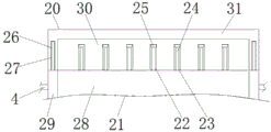
FIG. 4 is a top view of the shelf structure of the present invention;
FIG. 5 is an inside view of the shelf structure of the present invention.
In the figure: 1 rack supporting rod, 2 rack supporting foot frames, 3 rack plates, 4 connecting rotating rods, 5 connecting and fixing parts, 6 first stabilizing rods, 7 second stabilizing rods, 8 connecting and fixing openings, 9 extending fixing shafts, 10 fastening insertion openings, 11 extending connecting grooves, 12 limiting inner cavities, 13 limiting inner plates, 14 movement control openings, 15 adjusting inner cavities, 16 extending connecting rods, 17 supporting springs, 18 supporting inner plates, 19 rack cavities, 20 movable outer plates, 21 fixed inner plates, 22 contraction cavities, 23 connecting openings, 24 material blocking rods, 25 blocking plates, 26 extending blocking frames, 27 accommodating cavities, 28 fixing bottom plates, 29 fixing blocking frames, 30 movable bottom plates and 31 movable blocking frames.
Detailed Description
The technical solutions in the embodiments of the present invention will be clearly and completely described below with reference to the drawings in the embodiments of the present invention, and it is obvious that the described embodiments are only a part of the embodiments of the present invention, and not all of the embodiments. All other embodiments, which can be derived by a person skilled in the art from the embodiments given herein without making any creative effort, shall fall within the protection scope of the present invention.
Referring to fig. 1-5, a rack for two-dimensional artistic activities includes rack support rods 1, two rack support rods 1 fixedly connected to the bottom of the rack support rods 1, three rack plates 3 disposed between the two rack support rods 1, the three rack plates 3 arranged at the outer sides of the rack support rods 1 in an equidistant manner, first and second stabilizing rods 6 and 7 fixedly connected between the two rack support rods 1, the first stabilizing rod 6 located above the rack plate 3, the second stabilizing rod 7 located below the rack plate 3, both ends of the first stabilizing rod 6 and both ends of the second stabilizing rod 7 fixedly connected to the outer side surfaces of the rack support rods 1, the first stabilizing rod 6 and the second stabilizing rod 7 having the same volume, the bottom of the rack plate 3 fixedly connected to a connection 4, the two ends of the connecting rotating rod 4 are respectively movably connected with the outer side surfaces of the two rack supporting rods 1, the outer surface of each rack supporting rod 1 is movably connected with a connecting fixing piece 5, the outer side of each connecting fixing piece 5 is connected with the outer surface of the connecting rotating rod 4, a connecting fixing opening 8 is formed in each connecting fixing piece 5, the outer side of each connecting rotating rod 4 extends into the corresponding connecting fixing opening 8, fastening sockets 10 are formed in the front surface of each connecting fixing piece 5 and the back surface of each connecting fixing piece 5, an extending fixing shaft 9 is fixedly connected to the outer surface of each connecting rotating rod 4, one end of each extending fixing shaft 9 is connected with the corresponding fastening socket 10 in an inserting mode, each extending fixing shaft 9 is cylindrical, each fastening socket 10 is rectangular, the inner side surface of each fastening socket 10 is in contact with the outer surface of each extending fixing shaft 9, and, an adjusting inner cavity 15 is arranged in the article holding supporting foot rest 2, a movement control opening 14 is arranged on the outer surface of the article holding supporting foot rest 2, the adjusting inner cavity 15 is communicated with the outer side of the article holding supporting foot rest 2 through the movement control opening 14, one side of the connecting and fixing part 5 connected with the article holding supporting foot rest 2 is fixedly connected with an extension connecting rod 16, the other end of the extension connecting rod 16 far away from the connecting and fixing part 5 extends into the adjusting inner cavity 15 through the movement control opening 14, one end of the extension connecting rod 16 positioned in the adjusting inner cavity 15 is fixedly connected with a supporting inner plate 18, the width of the adjusting inner cavity 15 is larger than that of the movement control opening 14, the width of the supporting inner plate 18 is larger than that of the movement control opening 14, a supporting spring 17 is arranged in the adjusting inner cavity 15, one end of the supporting spring 17 is fixedly connected, the other end of the supporting spring 17 is fixedly connected with the inner wall of the adjusting inner cavity 15, the inner part of the rack supporting foot stand 2 is provided with a limiting inner cavity 12, the outer surface of the rack supporting foot stand 2 connected with the connecting rotating rod 4 is provided with an extending connecting groove 11, the limiting inner cavity 12 is communicated with the outer side of the rack supporting foot stand 2 through the extending connecting groove 11, the connecting rotating rod 4 extends to the inner part of the limiting inner cavity 12 through the extending connecting groove 11, one end of the extending connecting groove 11 positioned in the limiting inner cavity 12 is fixedly connected with a limiting inner plate 13, the width of the limiting inner cavity 12 is larger than that of the extending connecting groove 11, the width of the limiting inner plate 13 is larger than that of the extending connecting groove 11, one rack plate 3 is fixedly connected with the rack supporting rod 1 through two connecting fixing parts 5, and the number of the extending fixing, the connecting rotating rod 4 is inserted with a connecting and fixing part 5 through two extending fixing shafts 9, the extending fixing shafts 9 are symmetrically arranged on the outer surface of the connecting rotating rod 4, a placing cavity 19 is arranged above the placing plate 3, the placing plate 3 comprises a fixed inner plate 21, both sides of the fixed inner plate 21 are movably connected with movable outer plates 20, each movable outer plate 20 comprises a movable bottom plate 30, the top of each movable bottom plate 30 is fixedly connected with a movable blocking frame 31, each fixed inner plate 21 comprises a fixed bottom plate 28, the top of each fixed bottom plate 28 is fixedly connected with a fixed blocking frame 29, each fixed bottom plate 28 is connected with each movable bottom plate 30, each fixed blocking frame 29 is connected with each movable blocking frame 31, one side of each fixed bottom plate 28, which is connected with each movable bottom plate 30, is fixedly connected with a material blocking rod 24, a contraction cavity 22 is arranged inside each movable bottom plate 30, and one side of each movable bottom, shrink chamber 22 is linked together through connect opening 23 and movable bottom plate 30's the outside, the one end of baffle 25 is passed through connect opening 23 and is extended to shrink chamber 22's inside, material pin 24 is located the inside one end fixedly connected with baffle 25 in shrink chamber 22, shrink chamber 22's width value size is greater than connect opening 23's width value size, baffle 25's width value size is greater than connect opening 23's width value size, one side fixedly connected with that fixed fender frame 29 and activity fender frame 31 are connected extends and keeps off frame 26, movable fender frame 31 has been seted up with the one side that fixed fender frame 29 is connected and has been accomodate chamber 27, extend and keep off frame 26 and accomodate chamber 27 and peg graft mutually.
In summary, the following steps: the two-dimensional artistic rack for activities is convenient for fixing the connecting rotating rod 4 by arranging the connecting fixing piece 5, the rack plate 3 is convenient to control to rotate by the connecting rotating rod 4, so that the angle of the rack plate 3 is convenient to adjust, the rack plate 3 is convenient to fix by the connecting fixing piece 5, so that the rack plate 3 can store articles, the articles are not easy to fall off the rack plate 3, the connecting rotating rod 4 can not rotate by the connection between the fastening socket 10 and the extending fixing shaft 9, the fixing effect of the connecting rotating rod is realized, the connecting fixing piece 5 is convenient to control to move up and down by the supporting spring 17, so that the connecting fixing piece 5 is convenient to control to separate from the connecting rotating rod 4, the advantage of convenient control is achieved, the space size of the rack cavity 19 is convenient to increase by the adjustment between the movable outer plate 20 and the fixed inner plate 21, separate through control activity planking 20 and fixed inner panel 21 to make material pin 24 extend to the outside of activity planking 20, shelter from article through material pin 24, prevent that article from falling the outside of rack 3, improve the protection to article, and increased storing space, conveniently store more article, and conveniently carry out the regulation of rack 3, the advantage of being convenient for adjust has been reached, thereby the effectual inconvenient storage space who leads to the rack of adjusting of having solved current rack receives the restriction, thereby lead to some article can't be stored, thereby influence the rack and carry out the problem that article storage was put and is used.
It is noted that, herein, relational terms such as first and second, and the like may be used solely to distinguish one entity or action from another entity or action without necessarily requiring or implying any actual such relationship or order between such entities or actions. Also, the terms "comprises," "comprising," or any other variation thereof, are intended to cover a non-exclusive inclusion, such that a process, method, article, or apparatus that comprises a list of elements does not include only those elements but may include other elements not expressly listed or inherent to such process, method, article, or apparatus.
Although embodiments of the present invention have been shown and described, it will be appreciated by those skilled in the art that changes, modifications, substitutions and alterations can be made in these embodiments without departing from the principles and spirit of the invention, the scope of which is defined in the appended claims and their equivalents.
Claims (8)
1. A rack for two-dimensional artistic activities comprises a rack supporting rod (1), and is characterized in that: the bottom of each rack supporting rod (1) is fixedly connected with a rack supporting foot frame (2), the number of the rack supporting rods (1) is two, a rack plate (3) is arranged between the two rack supporting rods (1), the bottom of the rack plate (3) is fixedly connected with a connecting rotating rod (4), two ends of the connecting rotating rod (4) are respectively movably connected with the outer side surfaces of the two rack supporting rods (1), a connecting fixing piece (5) is movably connected with the outer surface of the rack supporting rods (1), the outer side of the connecting fixing piece (5) is connected with the outer surface of the connecting rotating rod (4), a connecting and fixing opening (8) is formed in the connecting and fixing piece (5), the outer side of the connecting rotating rod (4) extends to the inner side of the connecting and fixing opening (8), fastening sockets (10) are formed in the front surface of the connecting and the back surface of the connecting and fixing piece (5), the outer surface of the connecting rotating rod (4) is fixedly connected with an extending fixed shaft (9), one end of the extending fixed shaft (9) is connected with a fastening socket (10) in an inserting mode, the other end of the extending fixed shaft (9) extends to the outer side of the connecting fixing piece (5) through the fastening socket (10), an adjusting inner cavity (15) is formed in the rack supporting rod (1), a mobile control opening (14) is formed in the outer surface of the rack supporting rod (1), the adjusting inner cavity (15) is communicated with the outer side of the rack supporting rod (1) through the mobile control opening (14), an extending connecting rod (16) is fixedly connected to one side of the connecting fixing piece (5) connected with the rack supporting rod (1), the other end, far away from the connecting fixing piece (5), of the extending connecting rod (16) extends to the inner part of the adjusting inner cavity (15) through the mobile control opening (14), the utility model discloses a rack support, including extension connecting rod (16), regulation inner chamber (15), inner chamber (15) and limit inner chamber (12), the one end of support spring (17) and the bottom fixed connection who supports inner plate (18), the other end of support spring (17) and the inner wall fixed connection who adjusts inner chamber (15), limit inner chamber (12) have been seted up to the inside of rack bracing piece (1), extension spread groove (11) have been seted up to the surface that rack bracing piece (1) and connection dwang (4) are connected, limit inner chamber (12) are linked together through the outside of extension spread groove (11) with rack bracing piece (1), connect dwang (4) and extend to the inside of limit inner chamber (12) through extension spread groove (11), extension spread groove (11) are located the inside one end fixedly connected with of limit inner plate (13) of limit inner chamber (12), the storage rack is characterized in that a storage cavity (19) is formed above the storage rack (3), the storage rack (3) comprises a fixed inner plate (21), two sides of the fixed inner plate (21) are movably connected with movable outer plates (20), each movable outer plate (20) comprises a movable bottom plate (30), the top of each movable bottom plate (30) is fixedly connected with a movable blocking frame (31), each fixed inner plate (21) comprises a fixed bottom plate (28), the top of each fixed bottom plate (28) is fixedly connected with a fixed blocking frame (29), each fixed bottom plate (28) is connected with each movable bottom plate (30), each fixed blocking frame (29) is connected with each movable blocking frame (31), a material blocking rod (24) is fixedly connected to one side of each fixed bottom plate (28) connected with each movable bottom plate (30), a contraction cavity (22) is formed in each movable bottom plate (30), a connecting opening (23) is formed in one side of each movable bottom plate (30) connected with each fixed bottom plate (28), shrink chamber (22) are linked together through the outside of connecting opening (23) with movable bottom plate (30), and the one end of baffle (25) is passed through connecting opening (23) and is extended to the inside in shrink chamber (22), material pin (24) are located the inside one end fixedly connected with baffle (25) in shrink chamber (22), fixed one side fixedly connected with that keeps off frame (29) and activity fender frame (31) are connected extends and keeps off frame (26), the activity keeps off frame (31) and fixed one side that keeps off frame (29) and is connected and has seted up and accomodate chamber (27), extend and keep off frame (26) and accomodate chamber (27) and peg graft mutually.
2. The rack for a two-dimensional art activity according to claim 1, wherein: the number of the shelf plates (3) is three, and the three shelf plates (3) are arranged on the outer side of the shelf supporting rod (1) in an equidistant mode.
3. The rack for a two-dimensional art activity according to claim 1, wherein: a first stabilizing rod (6) and a second stabilizing rod (7) are fixedly connected between the two rack supporting rods (1), the first stabilizing rod (6) is positioned above the rack plate (3), the second stabilizing rod (7) is positioned below the rack plate (3), two ends of the first stabilizing rod (6) and two ends of the second stabilizing rod (7) are fixedly connected with the outer side surface of the rack supporting rods (1), and the volumes of the first stabilizing rod (6) and the second stabilizing rod (7) are equal.
4. The rack for a two-dimensional art activity according to claim 1, wherein: one shelf board (3) is connected mounting (5) and shelf bracing piece (1) fixed connection through two, and connects dwang (4) outside and extend the quantity of fixed axle (9) and be four, connect dwang (4) and extend fixed axle (9) and one through two and connect mounting (5) and peg graft mutually, just extend fixed axle (9) and arrange the surface of connecting dwang (4) with the form of symmetry.
5. The rack for a two-dimensional art activity according to claim 1, wherein: the width value of the adjusting inner cavity (15) is larger than that of the mobile control opening (14), and the width value of the supporting inner plate (18) is larger than that of the mobile control opening (14).
6. The rack for a two-dimensional art activity according to claim 1, wherein: the width value of restriction inner chamber (12) is greater than the width value size of extension connecting groove (11), the width value size of restriction inner panel (13) is greater than the width value size of extension connecting groove (11).
7. The rack for a two-dimensional art activity according to claim 1, wherein: the width value of shrink chamber (22) is greater than the width value of connecting opening (23), the width value of baffle (25) is greater than the width value of connecting opening (23) size.
8. The rack for a two-dimensional art activity according to claim 1, wherein: the extension fixing shaft (9) is cylindrical, the fastening socket (10) is rectangular, and the inner side surface of the fastening socket (10) is in contact with the outer surface of the extension fixing shaft (9).
Priority Applications (1)
| Application Number | Priority Date | Filing Date | Title |
|---|---|---|---|
| CN201810053456.2A CN108030259B (en) | 2018-01-19 | 2018-01-19 | Rack for two-dimensional artistic activities |
Applications Claiming Priority (1)
| Application Number | Priority Date | Filing Date | Title |
|---|---|---|---|
| CN201810053456.2A CN108030259B (en) | 2018-01-19 | 2018-01-19 | Rack for two-dimensional artistic activities |
Publications (2)
| Publication Number | Publication Date |
|---|---|
| CN108030259A CN108030259A (en) | 2018-05-15 |
| CN108030259B true CN108030259B (en) | 2020-04-28 |
Family
ID=62096897
Family Applications (1)
| Application Number | Title | Priority Date | Filing Date |
|---|---|---|---|
| CN201810053456.2A Active CN108030259B (en) | 2018-01-19 | 2018-01-19 | Rack for two-dimensional artistic activities |
Country Status (1)
| Country | Link |
|---|---|
| CN (1) | CN108030259B (en) |
Families Citing this family (1)
| Publication number | Priority date | Publication date | Assignee | Title |
|---|---|---|---|---|
| CN112704333A (en) * | 2020-11-24 | 2021-04-27 | 宁波东诚日用塑料制品有限公司 | Concatenation rack |
Family Cites Families (8)
| Publication number | Priority date | Publication date | Assignee | Title |
|---|---|---|---|---|
| FI7376U1 (en) * | 2006-09-12 | 2007-01-31 | Gws Pikval Oy | Sliding shelf locking mechanism |
| JP2013106923A (en) * | 2011-11-20 | 2013-06-06 | Lintec 21:Kk | Fall prevention tool |
| CN104515353B (en) * | 2013-09-30 | 2017-01-18 | 卧龙电气章丘海尔电机有限公司 | Adjustable rack of refrigerator and refrigerator |
| CN205030788U (en) * | 2015-10-13 | 2016-02-17 | 南阳医学高等专科学校 | Multi -functional archives management cabinet |
| GB2547931A (en) * | 2016-03-03 | 2017-09-06 | Wanzl Ltd | Shelf |
| CN107198355B (en) * | 2017-05-25 | 2019-05-07 | 李新亚 | Container Rotating rack |
| CN107348698A (en) * | 2017-07-20 | 2017-11-17 | 王琪 | A kind of novel environment friendly bookcase |
| CN107456005A (en) * | 2017-09-18 | 2017-12-12 | 苏州柯瑞德物流科技有限公司 | A kind of electric business shelf of fast demountable |
-
2018
- 2018-01-19 CN CN201810053456.2A patent/CN108030259B/en active Active
Also Published As
| Publication number | Publication date |
|---|---|
| CN108030259A (en) | 2018-05-15 |
Similar Documents
| Publication | Publication Date | Title |
|---|---|---|
| CA3048502C (en) | Multifunctional breathable storage cabinet | |
| CN108030259B (en) | Rack for two-dimensional artistic activities | |
| KR101460583B1 (en) | System furniture | |
| CN202760623U (en) | Multi-cabinet dressing table | |
| KR200452483Y1 (en) | Combination furniture set | |
| CN211186339U (en) | Make things convenient for multi-functional wardrobe of dismouting | |
| JP3091239U (en) | Assembling type multifunctional goods storage cabinet | |
| CN214548186U (en) | Multifunctional bookcase | |
| CN214207544U (en) | Multifunctional folding table cabinet | |
| CN217695665U (en) | Floor type storage rack | |
| CN211298938U (en) | Combined type trousers drawer | |
| CN219396687U (en) | Stainless steel cabinet with quick-assembly mortise and tenon structure | |
| CN212815976U (en) | Multifunctional storage rack | |
| CN218115913U (en) | Telescopic top-to-bottom clothes hanger | |
| CN215737791U (en) | Multifunctional medical bedside cabinet | |
| CN210407635U (en) | Clothes arrangement frame | |
| CN215456574U (en) | Domestic dining cabinet frame construction and dining cabinet | |
| CN207613430U (en) | Portable movable wardrobe | |
| CN212036645U (en) | Wardrobe for house | |
| CN220255998U (en) | Multifunctional wardrobe | |
| CN212394267U (en) | Wardrobe with multiple storage modes | |
| CN220726767U (en) | Stand bar buckle and combined cabinet | |
| CN210184991U (en) | Multifunctional bookshelf for life | |
| CN218588571U (en) | Assembled multifunctional cabinet | |
| CN210673153U (en) | Movable drawer grid |
Legal Events
| Date | Code | Title | Description |
|---|---|---|---|
| PB01 | Publication | ||
| PB01 | Publication | ||
| SE01 | Entry into force of request for substantive examination | ||
| SE01 | Entry into force of request for substantive examination | ||
| GR01 | Patent grant | ||
| GR01 | Patent grant |