CN107978773B - Gasket and fuel cell stack - Google Patents
Gasket and fuel cell stack Download PDFInfo
- Publication number
- CN107978773B CN107978773B CN201710992401.3A CN201710992401A CN107978773B CN 107978773 B CN107978773 B CN 107978773B CN 201710992401 A CN201710992401 A CN 201710992401A CN 107978773 B CN107978773 B CN 107978773B
- Authority
- CN
- China
- Prior art keywords
- point
- outer peripheral
- gasket
- quadrant
- stacking direction
- Prior art date
- Legal status (The legal status is an assumption and is not a legal conclusion. Google has not performed a legal analysis and makes no representation as to the accuracy of the status listed.)
- Active
Links
- 239000000446 fuel Substances 0.000 title claims abstract description 44
- 230000002093 peripheral effect Effects 0.000 claims abstract description 163
- 238000007789 sealing Methods 0.000 claims description 21
- 239000000853 adhesive Substances 0.000 claims description 6
- 230000001070 adhesive effect Effects 0.000 claims description 6
- 230000004048 modification Effects 0.000 description 37
- 238000012986 modification Methods 0.000 description 37
- 230000006835 compression Effects 0.000 description 30
- 238000007906 compression Methods 0.000 description 30
- 239000002826 coolant Substances 0.000 description 24
- 239000007789 gas Substances 0.000 description 21
- 230000001590 oxidative effect Effects 0.000 description 16
- 239000002737 fuel gas Substances 0.000 description 15
- 238000010586 diagram Methods 0.000 description 14
- 230000003449 preventive effect Effects 0.000 description 10
- 239000000463 material Substances 0.000 description 8
- 230000000694 effects Effects 0.000 description 6
- 239000012528 membrane Substances 0.000 description 4
- 239000007800 oxidant agent Substances 0.000 description 4
- 239000012495 reaction gas Substances 0.000 description 4
- 101000994463 Carassius auratus Keratin, type I cytoskeletal 50 kDa Proteins 0.000 description 3
- OKTJSMMVPCPJKN-UHFFFAOYSA-N Carbon Chemical compound [C] OKTJSMMVPCPJKN-UHFFFAOYSA-N 0.000 description 3
- LYCAIKOWRPUZTN-UHFFFAOYSA-N Ethylene glycol Chemical compound OCCO LYCAIKOWRPUZTN-UHFFFAOYSA-N 0.000 description 3
- UFHFLCQGNIYNRP-UHFFFAOYSA-N Hydrogen Chemical compound [H][H] UFHFLCQGNIYNRP-UHFFFAOYSA-N 0.000 description 3
- 229910052799 carbon Inorganic materials 0.000 description 3
- 229910052739 hydrogen Inorganic materials 0.000 description 3
- 239000001257 hydrogen Substances 0.000 description 3
- 230000002265 prevention Effects 0.000 description 3
- XLYOFNOQVPJJNP-UHFFFAOYSA-N water Substances O XLYOFNOQVPJJNP-UHFFFAOYSA-N 0.000 description 3
- 230000005484 gravity Effects 0.000 description 2
- 238000003475 lamination Methods 0.000 description 2
- 238000004519 manufacturing process Methods 0.000 description 2
- 229910052751 metal Inorganic materials 0.000 description 2
- 239000002184 metal Substances 0.000 description 2
- 125000006850 spacer group Chemical group 0.000 description 2
- 229910001200 Ferrotitanium Inorganic materials 0.000 description 1
- 230000009471 action Effects 0.000 description 1
- 239000000470 constituent Substances 0.000 description 1
- 229920001971 elastomer Polymers 0.000 description 1
- 239000003792 electrolyte Substances 0.000 description 1
- 239000012530 fluid Substances 0.000 description 1
- -1 for example Substances 0.000 description 1
- 230000012447 hatching Effects 0.000 description 1
- 238000001746 injection moulding Methods 0.000 description 1
- 239000007788 liquid Substances 0.000 description 1
- 230000013011 mating Effects 0.000 description 1
- 230000007246 mechanism Effects 0.000 description 1
- 238000000034 method Methods 0.000 description 1
- 238000000465 moulding Methods 0.000 description 1
- 239000002245 particle Substances 0.000 description 1
- 239000012466 permeate Substances 0.000 description 1
- 230000003134 recirculating effect Effects 0.000 description 1
- 230000009467 reduction Effects 0.000 description 1
- 239000011347 resin Substances 0.000 description 1
- 229920005989 resin Polymers 0.000 description 1
- 229910001220 stainless steel Inorganic materials 0.000 description 1
- 239000010935 stainless steel Substances 0.000 description 1
- 229920002725 thermoplastic elastomer Polymers 0.000 description 1
Images


Classifications
-
- H—ELECTRICITY
- H01—ELECTRIC ELEMENTS
- H01M—PROCESSES OR MEANS, e.g. BATTERIES, FOR THE DIRECT CONVERSION OF CHEMICAL ENERGY INTO ELECTRICAL ENERGY
- H01M8/00—Fuel cells; Manufacture thereof
- H01M8/02—Details
- H01M8/0271—Sealing or supporting means around electrodes, matrices or membranes
- H01M8/0273—Sealing or supporting means around electrodes, matrices or membranes with sealing or supporting means in the form of a frame
-
- H—ELECTRICITY
- H01—ELECTRIC ELEMENTS
- H01M—PROCESSES OR MEANS, e.g. BATTERIES, FOR THE DIRECT CONVERSION OF CHEMICAL ENERGY INTO ELECTRICAL ENERGY
- H01M8/00—Fuel cells; Manufacture thereof
- H01M8/02—Details
- H01M8/0202—Collectors; Separators, e.g. bipolar separators; Interconnectors
- H01M8/0247—Collectors; Separators, e.g. bipolar separators; Interconnectors characterised by the form
-
- H—ELECTRICITY
- H01—ELECTRIC ELEMENTS
- H01M—PROCESSES OR MEANS, e.g. BATTERIES, FOR THE DIRECT CONVERSION OF CHEMICAL ENERGY INTO ELECTRICAL ENERGY
- H01M8/00—Fuel cells; Manufacture thereof
- H01M8/02—Details
- H01M8/0202—Collectors; Separators, e.g. bipolar separators; Interconnectors
- H01M8/0258—Collectors; Separators, e.g. bipolar separators; Interconnectors characterised by the configuration of channels, e.g. by the flow field of the reactant or coolant
- H01M8/0265—Collectors; Separators, e.g. bipolar separators; Interconnectors characterised by the configuration of channels, e.g. by the flow field of the reactant or coolant the reactant or coolant channels having varying cross sections
-
- H—ELECTRICITY
- H01—ELECTRIC ELEMENTS
- H01M—PROCESSES OR MEANS, e.g. BATTERIES, FOR THE DIRECT CONVERSION OF CHEMICAL ENERGY INTO ELECTRICAL ENERGY
- H01M8/00—Fuel cells; Manufacture thereof
- H01M8/02—Details
- H01M8/0271—Sealing or supporting means around electrodes, matrices or membranes
- H01M8/0276—Sealing means characterised by their form
-
- H—ELECTRICITY
- H01—ELECTRIC ELEMENTS
- H01M—PROCESSES OR MEANS, e.g. BATTERIES, FOR THE DIRECT CONVERSION OF CHEMICAL ENERGY INTO ELECTRICAL ENERGY
- H01M8/00—Fuel cells; Manufacture thereof
- H01M8/24—Grouping of fuel cells, e.g. stacking of fuel cells
- H01M8/241—Grouping of fuel cells, e.g. stacking of fuel cells with solid or matrix-supported electrolytes
- H01M8/242—Grouping of fuel cells, e.g. stacking of fuel cells with solid or matrix-supported electrolytes comprising framed electrodes or intermediary frame-like gaskets
-
- H—ELECTRICITY
- H01—ELECTRIC ELEMENTS
- H01M—PROCESSES OR MEANS, e.g. BATTERIES, FOR THE DIRECT CONVERSION OF CHEMICAL ENERGY INTO ELECTRICAL ENERGY
- H01M8/00—Fuel cells; Manufacture thereof
- H01M8/24—Grouping of fuel cells, e.g. stacking of fuel cells
- H01M8/2457—Grouping of fuel cells, e.g. stacking of fuel cells with both reactants being gaseous or vaporised
-
- H—ELECTRICITY
- H01—ELECTRIC ELEMENTS
- H01M—PROCESSES OR MEANS, e.g. BATTERIES, FOR THE DIRECT CONVERSION OF CHEMICAL ENERGY INTO ELECTRICAL ENERGY
- H01M8/00—Fuel cells; Manufacture thereof
- H01M8/24—Grouping of fuel cells, e.g. stacking of fuel cells
- H01M8/2465—Details of groupings of fuel cells
- H01M8/2483—Details of groupings of fuel cells characterised by internal manifolds
-
- H—ELECTRICITY
- H01—ELECTRIC ELEMENTS
- H01M—PROCESSES OR MEANS, e.g. BATTERIES, FOR THE DIRECT CONVERSION OF CHEMICAL ENERGY INTO ELECTRICAL ENERGY
- H01M8/00—Fuel cells; Manufacture thereof
- H01M8/24—Grouping of fuel cells, e.g. stacking of fuel cells
- H01M8/2465—Details of groupings of fuel cells
- H01M8/2484—Details of groupings of fuel cells characterised by external manifolds
- H01M8/2485—Arrangements for sealing external manifolds; Arrangements for mounting external manifolds around a stack
-
- H—ELECTRICITY
- H01—ELECTRIC ELEMENTS
- H01M—PROCESSES OR MEANS, e.g. BATTERIES, FOR THE DIRECT CONVERSION OF CHEMICAL ENERGY INTO ELECTRICAL ENERGY
- H01M8/00—Fuel cells; Manufacture thereof
- H01M8/10—Fuel cells with solid electrolytes
- H01M2008/1095—Fuel cells with polymeric electrolytes
-
- Y—GENERAL TAGGING OF NEW TECHNOLOGICAL DEVELOPMENTS; GENERAL TAGGING OF CROSS-SECTIONAL TECHNOLOGIES SPANNING OVER SEVERAL SECTIONS OF THE IPC; TECHNICAL SUBJECTS COVERED BY FORMER USPC CROSS-REFERENCE ART COLLECTIONS [XRACs] AND DIGESTS
- Y02—TECHNOLOGIES OR APPLICATIONS FOR MITIGATION OR ADAPTATION AGAINST CLIMATE CHANGE
- Y02E—REDUCTION OF GREENHOUSE GAS [GHG] EMISSIONS, RELATED TO ENERGY GENERATION, TRANSMISSION OR DISTRIBUTION
- Y02E60/00—Enabling technologies; Technologies with a potential or indirect contribution to GHG emissions mitigation
- Y02E60/30—Hydrogen technology
- Y02E60/50—Fuel cells
Abstract
The invention provides a gasket and a fuel cell stack. The seal portion has an outer peripheral point having a first length L1 from a center point, the outer peripheral point being a point on an outer peripheral line in a first range of 0 to 90 degrees with respect to the stacking direction with the center point as a center, L2 is equal to or less than L1 when a distance from the center point is a second length L2 for each point on the outer peripheral line in the first range of the first direction from the center point toward the outer peripheral point and the stacking direction, L3< L1 when a distance from the center point is L3 for each point on the outer peripheral line in a second range of the first direction from the direction perpendicular to the stacking direction, and each point on the outer peripheral line in the second range is located on the opposite side of the center point or at the same position as the outer peripheral point with respect to the outer peripheral point in the direction perpendicular to the stacking direction.
Description
Technical Field
The present invention relates to a gasket used for a fuel cell stack, and a fuel cell stack.
Background
In general, a fuel cell stack has a stack structure in which a plurality of unit cells are stacked. Each of the unit cells has a membrane electrode assembly and two separators sandwiching the membrane electrode assembly. Since the reaction gas flow path, the coolant flow path, the reaction gas manifold, and the coolant manifold are formed in the separator, a gasket for suppressing leakage of each fluid is appropriately provided around the reaction gas flow path, the coolant flow path, the reaction gas manifold, and the coolant manifold. A non-adhesive type gasket having a main lip which is closely attached to a separator is disclosed in japanese patent laid-open No. 2006-4851.
Disclosure of Invention
In the structure using the gasket of the related art, when a compressive force is applied from a direction intersecting the stacking direction, the gasket may be inclined with the longitudinal direction as an axis, and the main lip portion protruding in the stacking direction may be displaced from the surface of the separator. In this case, sufficient surface pressure cannot be applied between the unit cells of the fuel cell stack, and sufficient sealing performance cannot be ensured. Therefore, a technique capable of ensuring sufficient sealing performance in a non-adhesive type gasket is desired.
A first aspect of the present invention relates to a gasket that is disposed between separators of unit cells of two fuel cell stacks adjacent in a stacking direction so as not to adhere to each other, and seals the separators. The gasket has a seal portion that is in close contact with the two separators. In a cross section perpendicular to a longitudinal direction of the seal portion, the seal portion has an outer peripheral point having a first length L1 from a center point of the seal portion, the outer peripheral point being a point on an outer peripheral line within a range of a right angle of 0 to 90 degrees with respect to the stacking direction with the center point as a center, has a relationship of L2 ≦ L1 when a distance from the center point to each point on the outer peripheral line within a first angle range of a first direction from the center point toward the outer peripheral point and the stacking direction is set to a second length L2, has a relationship of L3< L1 when a distance from the center point to each point on an outer peripheral line within a second angle range of the first direction and a direction perpendicular to the stacking direction is set to L3, and has a relationship of L3< L1 with each point on the outer peripheral line within the second angle range being located on a side opposite to the center point or opposite to the outer peripheral point in the direction perpendicular to the stacking direction The same position of the peripheral points.
According to this gasket, there is an outer peripheral point in a right angle range from 0 degrees to 90 degrees, and a length (distance) L2 from a center point of each point on an outer peripheral line in a first angle range on the 0 degree side of the outer peripheral point is equal to or less than a length (distance) L1 from the center point to the outer peripheral point. Therefore, in the outer peripheral line in the first angle range, the outer peripheral point becomes the farthest portion from the center point. When the pad is inclined with the longitudinal direction as an axis, the orientation of the outer peripheral point with respect to the center point may be caused to function so as to approach the compression direction of the pad. Therefore, even when the gasket is inclined, a sufficient thickness contributing to the sealing property can be secured. Further, according to this gasket, the distance L3 from the center point of each point on the outer peripheral line in the second angular range on the 90-degree side of the outer peripheral point is shorter than the length (distance) L1 from the center point to the outer peripheral point, and each point on the outer peripheral line in the second angular range is located on the opposite side of the center point or at the same position as the outer peripheral point with respect to the outer peripheral point in the direction perpendicular to the stacking direction. Therefore, the gasket material can be reliably filled in the compression range in a view from the compression direction. Therefore, a decrease in the reaction force during compression can be suppressed. Therefore, according to this gasket, even when the gasket is inclined, a portion in close contact with the separator can be secured, and reduction in the reaction force during compression can be suppressed, so that the effect of being able to sufficiently apply the surface pressure between the separators of the fuel cell stack and securing sufficient sealing performance is exhibited.
The outer circumferential point may be a point farthest from the center point among a row of points constituting an outer circumferential line of the seal portion. In this way, a portion that comes into close contact with the separator when the gasket is inclined can be further secured.
The outer peripheral line of the seal portion may have a circular arc-shaped portion centered on the center point and having the first length as a radius, and the outer peripheral point may be a point having a longest distance from the center point in a direction perpendicular to the stacking direction among the rows of points constituting the circular arc-shaped portion. In this way, when the gasket is inclined, the portion in close contact with the separator can be ensured to be the arc-shaped portion.
Each point on the outer peripheral line in the second angular range may be gradually increased in distance from the center point in a direction perpendicular to the stacking direction as approaching the center point in the stacking direction. Thus, sufficient sealing performance can be ensured with a simple shape.
The seal portion may include an O-ring portion having a circular cross section and a first protrusion portion disposed on an outer periphery of the O-ring portion, and the outer peripheral point may be a vertex of the first protrusion portion. Thus, the outer circumferential point can be easily obtained, and sufficient sealing performance can be ensured.
When a coordinate plane having the center point as an origin is assumed in the cross section, the rectangular range may correspond to a first quadrant located at an upper right in the coordinate plane, and a portion of the seal portion included in a second quadrant located at an upper left may be line-symmetric to a portion of the seal portion included in the first quadrant. In this way, since the outer circumferential points can be obtained at both the first quadrant portion and the second quadrant portion, more sufficient sealing performance can be ensured.
The sealing member may include plate-shaped peripheral portions provided on both sides of the sealing member in a direction perpendicular to the stacking direction, and the outer peripheral line in the second angular range may not include a portion of the sealing member connected to the peripheral portions. In this way, the peripheral edge portion abuts against the separator, and the gasket can be prevented from tilting about the longitudinal direction.
The second projecting portion may be provided so as to project from a surface of the peripheral edge portion in the stacking direction. In this way, the second projecting portion abuts against the separator, thereby further suppressing the gasket from tilting about the longitudinal direction.
A second aspect of the present invention relates to a fuel cell stack in which a plurality of unit cells are stacked in a stacking direction. The fuel cell includes the gasket according to the first aspect. According to this fuel cell stack, even when the gasket is inclined, the space between the separators can be sufficiently sealed.
Drawings
The features, advantages and technical and industrial significance of exemplary embodiments of the present invention will be explained below with reference to the accompanying drawings. In the drawings, like numbering represents like elements.
Fig. 1 is an explanatory diagram showing a schematic configuration of a fuel cell system according to a first embodiment of the present invention.
Fig. 2 is a schematic plan view of an anode-side separator of a single cell viewed from the opposite side of the MEA.
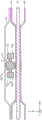
Fig. 3 is an explanatory view showing a cross section III-III of the anode-side separator shown in fig. 2.
Fig. 4 is an explanatory view showing a cross section perpendicular to the longitudinal direction of the gasket.
Fig. 5 is an explanatory diagram showing a state in which the pad is inclined with the longitudinal direction as an axis.
Fig. 6 is an explanatory view showing a cross section perpendicular to the longitudinal direction of the gasket of the third reference example.
Fig. 7 is an explanatory view showing a cross section perpendicular to the longitudinal direction of the gasket of the fourth reference example.
Fig. 8 is an explanatory view showing a part of a gasket according to a first modification of the first embodiment.
Fig. 9 is an explanatory view showing a gasket according to a second embodiment of the present invention.
Fig. 10 is an explanatory diagram showing a state in which the pad of the second embodiment is inclined with the longitudinal direction as an axis.
Fig. 11 is an explanatory view showing a part of a gasket according to a first modification of the second embodiment.
Fig. 12 is an explanatory view showing a gasket according to a second modification of the second embodiment.
Fig. 13 is an explanatory view showing an anode-side separator provided with a gasket according to a third embodiment.
Fig. 14 is an explanatory view showing a part of a gasket according to a modification of the third embodiment.
Detailed Description
A. The first embodiment:
a-1. the overall structure of the fuel cell system:
fig. 1 is an explanatory diagram showing a schematic configuration of a fuel cell system 10 according to a first embodiment of the present invention. The fuel cell system 10 includes a fuel cell stack 100. The fuel cell stack 100 has a stack structure in which an end plate 110, an insulating plate 120, a current collector plate 130, a plurality of unit cells 140 of the fuel cell stack 100, the current collector plate 130, the insulating plate 120, and the end plate 110 are stacked in this order. The stacking direction of the cells 140 is a direction Z perpendicular to the vertical direction Y. One end plate 110 and the other end plate 110 are fastened by applying a compressive force by four fastening bolts (not shown).
Hydrogen as a fuel gas is supplied from a hydrogen tank 150 in which high-pressure hydrogen is stored to the fuel cell stack 100 through a shut-off valve 151, a regulator 152, and a pipe 153. The fuel gas (anode off-gas) that is not used in the fuel cell stack 100 is discharged to the outside of the fuel cell stack 100 through the discharge pipe 163. The fuel cell system 10 may include a recirculation mechanism for recirculating the anode off-gas to the pipe 153. Air as the oxidizing gas is supplied to the fuel cell stack 100 through the air pump 160 and the pipe 161. The oxidant gas (cathode off-gas) that is not used in the fuel cell stack 100 is discharged to the outside of the fuel cell stack 100 through the discharge pipe 154. The fuel gas and the oxidant gas are also referred to as reaction gases.
In order to cool the fuel cell stack 100, the cooling medium cooled by the radiator 170 is supplied to the fuel cell stack 100 via the water pump 171 and the pipe 172. The cooling medium discharged from the fuel cell stack 100 is circulated to the radiator 170 through the pipe 173. As the cooling medium, for example, water, an unfrozen liquid such as ethylene glycol, air, or the like can be used. In this example, water is used as the cooling medium.
Each cell 140 included in the fuel cell stack 100 is configured to sandwich a membrane electrode assembly (also referred to as MEA)30, in which an anode and a cathode are disposed on both surfaces of an electrolyte membrane, respectively, by an anode-side separator 50 and a cathode-side separator 40, which are a pair of separators. The anode-side separator 50 includes a plurality of fuel gas flow channels 52 in a rib shape on the face on the MEA30 side, and a plurality of cooling medium flow channels 54 in a rib shape on the face on the opposite side from the MEA 30. The cathode-side separator 40 includes a plurality of rib-like oxidizing gas flow path grooves 42 on the MEA 30-side surface. The frame member 32 made of resin having insulating properties is provided on the outer periphery of the MEA30 sandwiched between the anode side separator 50 and the cathode side separator 40.
Fig. 2 is a schematic plan view of the anode-side separator 50 of the unit cell 140 viewed from the side opposite to the MEA 30. In fig. 2, the front-back direction is the stacking direction Z, and the vertical direction Y is the vertical direction. In this specification, the vertical direction Y includes a direction of gravity and a direction opposite to the gravity. The horizontal direction in the drawing perpendicular to the vertical direction Y and the stacking direction Z is the horizontal direction X. The anode separator 50 and the cathode separator 40 are made of a member having gas-blocking properties and electron-conducting properties, and are formed of, for example, a carbon member such as dense carbon that is compressed with carbon particles and does not allow gas to permeate therethrough, or a metal member such as press-formed stainless steel or titanium steel. In the present embodiment, the separators 40, 50 are metal stamped separators.
The fuel gas inlet manifold 62, the coolant outlet manifold 84, and the oxidant gas inlet manifold 72 are arranged in this order from above along the vertical direction Y at one end edge portion in the horizontal direction X of the anode-side separator 50. On the other hand, the oxidizing gas outlet manifold 74, the cooling medium inlet manifold 82, and the fuel gas outlet manifold 64 are arranged in this order from the top in the vertical direction Y at the other end edge portion. The fuel gas inlet manifold 62 and the fuel gas outlet manifold 64 are disposed so as to be point-symmetrical with respect to the outer edge portions on both sides in the horizontal direction X. The oxidizing gas inlet manifold 72 and the oxidizing gas outlet manifold 74 are disposed so as to be point-symmetrical with respect to the outer edge portions on both sides in the horizontal direction X. The coolant inlet manifold 82 and the coolant outlet manifold 84 are disposed so as to be point-symmetrical with respect to the outer edge portions on both sides in the horizontal direction X.
The fuel gas supplied from the fuel gas inlet manifold 62 is distributed to the fuel gas flow path grooves 52 (fig. 1) of the unit cells 140, and thereafter, the fuel gas unused in the fuel gas flow path grooves 52 is collected by the fuel gas outlet manifold 64 and discharged to the outside of the fuel cell stack 100. The oxidizing gas supplied from the oxidizing gas inlet manifold 72 is distributed to the oxidizing gas flow channels 42 (fig. 1) of the unit cells 140, and thereafter, the oxidizing gas that is not used in the oxidizing gas flow channels 42 is collected by the oxidizing gas outlet manifold 74 and discharged to the outside of the fuel cell stack 100.
The coolant supplied from the coolant inlet manifold 82 diffuses through one end of the anode-side separator 50 where the dimples 56 are provided, flows through the coolant flow channel 54, is collected from the coolant flow channel 54 through the other end where the dimples 56 are provided by the coolant outlet manifold 84, and is discharged to the outside of the fuel cell stack 100. In a plane of the anode-side separator 50 viewed from the side opposite to the MEA30, the cooling medium inlet manifold 82, the cooling medium flow channel groove 54, and the cooling medium outlet manifold 84 communicate with each other in the horizontal direction X to constitute a cooling medium flow surface 200. The openings of the manifolds 62, 64, 72, 74, 82, and 84 are substantially rectangular. Each manifold has a shape extending in the stacking direction Z of the fuel cell stack 100.
Gaskets GK1 to GK5 that surround the manifolds 62, 64, 72, and 74 and the coolant flow field surface 200 are formed on a plane of the anode-side separator 50 viewed from the side opposite to the MEA 30. The gaskets GK1 to GK5 are seal members that constitute closed (both ends overlapping) linear seal lines and seal (seal) the space between two adjacent unit cells 140 by abutting against the surface of another unit cell 140 when the plurality of unit cells 140 are stacked. Specifically, the gaskets GK1 and GK2 suppress leakage of the fuel gas, the gaskets GK3 and GK4 suppress leakage of the oxidizing gas, and the gasket GK5 suppresses leakage of the cooling medium. The gaskets GK1 to GK5 are formed by injection molding, press molding, or the like, and as the material of the gaskets GK1 to GK5, rubber, thermoplastic elastomer, or the like can be used. The groove 80 is formed in a region where these gaskets GK1 to GK5 are arranged (a part of a plane of the anode-side separator 50 viewed from the side opposite to the MEA 30). The gaskets GK1 to GK5 have no cavity.
A-2. Structure of the gasket:
a plan view of the gasket GK4 formed near the oxidant gas outlet manifold 74 of the anode-side separator 50 is shown in fig. 2. The gasket GK4 extends in a direction along the seal line, and includes a center seal portion 21 near the center in the width direction of the seal line, and peripheral edge portions 22 on both sides of the center seal portion 21 (see fig. 3). The central seal portion 21 is formed integrally with the peripheral edge portion 22.
Fig. 3 is an explanatory view showing a cross section III-III of the anode-side separator 50 shown in fig. 2. The III-III cross section is a cross section perpendicular to the longitudinal direction (linear extending direction) of the pad GK 4. The center seal portion 21 of the gasket GK4 functions to be in close contact with the anode-side separator 50 of one of the adjacent two cells 140 and the cathode-side separator 40 of the other cell 140 in a state where the plurality of cells 140 (fig. 2) are stacked. The peripheral edge portion 22 of the gasket GK4 has a flat plate shape, and is connected to both sides of the central seal portion 21 in the horizontal direction X and near the center in the stacking direction Z. The peripheral edge portion 22 is formed to have a smaller thickness than the central seal portion 21. In the present specification, "thickness" refers to a dimension in the stacking direction Z of the unit cells 140. The width Wg of the gasket GK4 is smaller than the width Ws of the groove 80, and the gasket GK4 is disposed in the groove 80. The shape characteristics of the pad GK4 are similar to those of the other pads GK1 to GK3 and GK 5.
When the fuel cell stack 100 is assembled, the cathode-side separator 40 of another adjacent cell 140 abuts against the anode-side separator 50 in a state where the gaskets GK1 to GK5 are disposed in the grooves 80 formed in the anode-side separator 50 of the cell 140. Fig. 3 shows a state immediately before the abutment. In the drawing, the cathode-side separator 40 of the other adjacent unit cell 140 is indicated by a broken line. At this time, the center seal portion 21 of the gasket GK4 is in contact with the cathode-side separator 40 and the anode-side separator 50.
Fig. 4 is an explanatory diagram showing a cross section perpendicular to the longitudinal direction of the pad GK 4. Hatching for showing the cross section is omitted as necessary in the drawings. The central seal portion 21 of the gasket GK4 has the following shape characteristics in a cross section perpendicular to the longitudinal direction. The central seal portion 21 may be regarded as a "seal portion" in the first aspect of the present invention described in the section of the "summary of the invention".
The coordinate plane along the cross section is divided into a first quadrant (portion of X >0, Z > 0), a second quadrant (portion of X <0, Z > 0), a third quadrant (portion of X <0, Z < 0), and a fourth quadrant (portion of X >0, Z < 0) by a coordinate axis along the horizontal direction X (hereinafter, referred to as "X coordinate axis") and a coordinate axis along the stacking direction Z (hereinafter, referred to as "Z coordinate axis"). The origin at which the X coordinate axis and the Z coordinate axis intersect coincides with the center point O in the cross section of the central seal portion 21.
In the central sealing portion 21, the portions of the first and second quadrants are symmetrical with respect to the Z-axis, the portions of the first and third quadrants are point-symmetrical with respect to the center point O, and the portions of the first and fourth quadrants are symmetrical with respect to the X-axis. Hereinafter, the first quadrant will be described as a representative of the second to fourth quadrants.
As described above, the first quadrant is a portion where X >0 and Z > 0. In other words, the first quadrant is a portion within an angular range (right angle range) from 0 degrees to 90 degrees clockwise with respect to the + side of the Z coordinate axis (hereinafter referred to as "+ Z coordinate axis") in the cross section perpendicular to the longitudinal direction of the center seal portion 21. The portion of the first quadrant may be considered "within the right angle range" in the first aspect of the present invention.
In the first quadrant, the outer periphery (outer peripheral line) of the center seal portion 21 includes an outer peripheral upper portion 21a, an outer peripheral intermediate portion 21b, and outer peripheral side portions 21 c.
The outer peripheral upper portion 21a is a portion on the upper side (+ Z side) in the drawing of the stacking direction Z, and is formed in a linear shape parallel to the X coordinate axis. That is, the outer peripheral upper portion 21a has a planar shape parallel to the X-Y plane. The distance between the outer peripheral upper portion 21a and the X coordinate axis is h.
The outer peripheral middle portion 21b is a portion continuous with the + X-side (the + side in the X coordinate axis direction, the same applies hereinafter) end portion of the outer peripheral upper portion 21a, and is a corner portion of the central seal portion 21 having a rounded corner. Specifically, the outer peripheral intermediate portion 21b is a portion from P1 to point P2 on the outer peripheral line of the center seal portion 21, and is formed in a shape along an arc of a radius r with the center point O as the center. The radius r is longer than the distance h. The + X-side end of the outer peripheral intermediate portion 21b, i.e., the point P1, is located in a direction that makes an angle α clockwise with respect to the + Z coordinate axis. The angle alpha is for example 35 degrees. The 35 degrees is an example, and can be converted into various values. The point P1 may be regarded as the "outer peripheral point" in the first aspect of the invention.
The circle CR shown by a dotted line in the figure is a circle of radius r centered on the center point O. The outer peripheral middle portion 21b is along a part of the circle CR, and the outer peripheral upper portion 21a is located inside (on the center point O side) the circle CR. Therefore, each point (for example, point P2) on the outer peripheral line has a relationship of the following equation (1) in an angular range (portion α in the figure) formed by the direction from the center point O to the point P1 and the + Z coordinate axis. This angular range may be regarded as "first angular range" in the first aspect of the present invention, and hereinafter, referred to as "first angular range α".
L2≤r…(1)
Here, L2 is the distance from the center point O to the point P2. r is the distance from the center point O to the point P1 as described above, and may be regarded as "the first length L1" in the first aspect of the present invention.
The outer peripheral side portion 21c is a portion continuous with a point P1, which is the + X-side end portion of the outer peripheral intermediate portion 21b, and functions as an outer peripheral line in an angular range (a range of β in fig. 4) formed by the + X coordinate axis in a direction from the center point O toward the point P1. This angular range may be regarded as "second angular range" in the first aspect of the present invention, and hereinafter, referred to as second angular range β. In the outer peripheral line of the gasket GK4 in the first quadrant, the range occupied by the outer peripheral line of the center seal portion 21 is a portion from the point P1 to the point P3 within the second angular range β. Point P3 is the boundary point between the central seal portion 21 and the peripheral edge portion 22. The portion from the point P1 to the point P3 functions as an outer peripheral line in the second angular range β. In the present specification, the outer peripheral line is a line that forms a boundary with the outside (atmosphere side), and is a portion from point P1 to point P3 in the central seal portion 21. The outer peripheral line does not include a portion of the central seal portion 21 connected to the peripheral edge portion 22, that is, a portion not open to the atmosphere.
The outer peripheral side portion 21c is formed in a convex shape bulging toward the + X side in the X coordinate axis direction than a straight line LN in the stacking direction Z passing through the point P1. Specifically, the smaller the value of the Z-axis, the more gradually the value of the X-axis increases. However, the outer peripheral side portion 21c is present on the inner side (center point O side) of the circle CR.
The outer peripheral side portion 21c may be defined as follows. Each point on the outer peripheral side portion 21c, that is, each point on the outer peripheral line within the second angular range β (for example, one point is a point P4 in fig. 4) has a relationship of the following mathematical expression (2).
L3<r…(2)
Here, L3 is the distance from the center point O to each point on the outer peripheral line (e.g., point P4). r is the distance from the center point O to the point P1, previously described, i.e. the radius of the circle CR.
Further, each point on the outer peripheral side portion 21c, that is, each point on the outer peripheral line within the second angular range β (for example, the point P4 in the drawing is one of the points) is located on the opposite side (that is, the + X side) from the center point O with respect to the point P1 in the X coordinate axis direction. In the present embodiment, each point is located on the opposite side of the center point O (i.e., + X side) with respect to the point P1 in the X coordinate axis direction, but may be located at the same position as the point P1 in the X coordinate axis direction instead of this. The dot row constituting the outer peripheral side portion 21c may be all or a part of the dot row located at the same position as the point P1.
Of the outer peripheral upper portion 21a, the outer peripheral intermediate portion 21b, and the outer peripheral side portion 21c, the outer peripheral intermediate portion 21b is farthest from the center point O. Therefore, the outer peripheral intermediate portion 21b can be said to be a set of points that are at the farthest distance (r) from the center point O (hereinafter, these points are referred to as "outermost points") among the rows of points that constitute the outer peripheral line of the seal portion.
When a compressive force is applied between the anode-side separator 50 and the cathode-side separator 40 of the other adjacent cell 140 from the state of fig. 3, the gasket GK4 is compressed in the stacking direction Z, and a surface pressure is applied to the separators 40, 50 by the restoring force. Specifically, the center seal portion 21 of the gasket GK4 deforms in the stacking direction Z, and a surface pressure is applied to each separator 40, 50 by the restoring force of the center seal portion 21. As a result, the center seal portion 21 is in close contact with the surface of the anode-side separator 50 and the surface of the cathode-side separator 40 of the adjacent other cell 140, and seals the cell 140 and the adjacent other cell 140.
As described above, the peripheral edge portions 22 are provided on both sides of the central seal portion 21. The peripheral edge portion 22 functions to regulate the degree of inclination of the gasket GK about the longitudinal direction as an axis, that is, to prevent falling. The peripheral edge portion 22 does not function so as to be in close contact with the anode side separator 50 of one of the two adjacent unit cells and the cathode side separator 40 of the other unit cell.
A-3, action effect:
as described above in detail, according to the gaskets GK1 to GK5 of the present embodiment, the center seal portion 21 has the point P1 as one point on the outer peripheral line in the angular range of the first quadrant in the cross section perpendicular to the longitudinal direction. Each point (for example, point P2) on the outer peripheral line in the first angular range (range of α in fig. 4) on the side of the angle of 0 degrees with respect to the Z axis from the point P1 has the relationship of the above-described mathematical expression (1). Specifically, the length (distance) L2 from the center point O to each point is equal to or less than the distance r from the center point O to the point P1. That is, in the outer peripheral lines (the outer peripheral upper portion 21a and the outer peripheral intermediate portion 21b) in the first angle range, there is no portion (point) having a length (distance) L2 from the center point O that is farther than the point P1. With respect to the portion of the outer peripheral intermediate portion 21b other than the point P1, although departing from the center point O to the same extent as the point P1, it is not farther apart than the point P1.
Fig. 5 is an explanatory diagram showing a state in which the pad GK4 is tilted about the longitudinal direction as an axis. For example, when the fastening pressures of the four fastening bolts are not equal to each other, a compressive force may be applied to the gasket GK4 from a direction intersecting the stacking direction Z. In this case, the pad GK4 may be entirely or partially inclined about the longitudinal direction as an axis. For example, as shown in fig. 5, the center point O may be inclined counterclockwise. At this time, the pad GK4 according to the present embodiment functions such that the outer peripheral intermediate portion 21b including the point P1 (fig. 4) is located closer to the center point O in the compression direction of the pad GK 4. Therefore, even when the gasket GK4 is inclined, a sufficient thickness contributing to the sealing property can be secured.
In a cross section perpendicular to the longitudinal direction of the central seal portion 21, as described with reference to fig. 4, each point (for example, point P4) on the outer peripheral line in a second angular range (range of β in fig. 4) on the 90 ° side of the point P1 has the relationship of the above-described equation (2). Specifically, the distance L3 from the center point O to each of the points is shorter than the distance r from the center point O to the point P1. Further, the respective points are located on the opposite side of the center point O or at the same position as the point P1 with respect to the point P1 in the X coordinate axis direction. Therefore, the gaskets GK1 to GK5 can reliably fill the compression range with the gasket material when viewed from the compression direction, and can suppress a decrease in the reaction force during compression.
Therefore, according to the gaskets GK1 to GK5 of the present embodiment, even when the gaskets GK1 to GK5 are inclined, since a portion in close contact with the separator 40 can be secured and a decrease in the reaction force during compression can be suppressed, a sufficient surface pressure can be applied between the separators 40 and 50 of the fuel cell stack 100. As a result, the gaskets GK1 to GK5 exhibit an effect of being able to ensure sufficient sealing properties.
The advantages of the gaskets GK1 to GK5 (hereinafter, also simply referred to as "gasket GK") according to the present embodiment will be further described by comparison with gaskets of other shapes. In the gasket described in jp 2006-a 4851 a (hereinafter, referred to as "gasket of the first reference example"), as described in the section of [ summary of the invention ], the tip end of the main ridge is displaced from the mating seal surface, and sufficient sealability cannot be ensured. In contrast, the gasket GK of the present embodiment can secure a portion in close contact with the separator 40 even when the gasket GK is inclined as described above, and therefore can sufficiently apply a surface pressure between the cells.
Hereinafter, a bonding type gasket having a main lip in a chevron shape similar to the above gasket and having a bottom surface bonded to the separator will be described as a gasket of a second reference example. According to the gasket of the second reference example, since the gasket is bonded to the separators, the gasket does not tilt between the separators. Therefore, according to the gasket of the second reference example, the surface pressure drop caused by the inclination of the gasket can be prevented. However, the gasket according to the second reference example requires the steps of surface management of the separator, application of the adhesive, and curing at the time of assembly, and the manufacturing of the fuel cell stack takes time and labor. In contrast, since the gasket GK of the present embodiment is a non-adhesive type, assembly is easy, and manufacturing of the fuel cell stack is easy.
Fig. 6 is an explanatory diagram showing a cross section perpendicular to the longitudinal direction of the spacer GK90 of the third reference example. The cross section of the gasket GK90 is formed in a circular shape. The gasket GK90 is a so-called O-ring. The gasket GK90 has a larger width in the horizontal direction X perpendicular to the stacking direction Z than the gasket GK of the present embodiment, and therefore the gasket material has a larger volume. Therefore, in the gasket GK90 of the third reference example, in order to obtain high sealability, it is necessary to compress the gasket with a high compression force, but in this case, the internal stress increases and the strain increases. In contrast, in the gasket GK of the present embodiment, since each point on the outer peripheral side portion 21c of the center seal portion 21, that is, each point on the outer peripheral line in the second angular range β has the relationship of the above-described mathematical expression (2) (L3< r), the width in the horizontal direction X is smaller than the gasket GK90 of the third reference example. Therefore, the gasket GK of the present embodiment can have a low internal stress at high compression and can be formed with a low strain.
Fig. 7 is an explanatory diagram showing a cross section perpendicular to the longitudinal direction of the spacer GK92 of the fourth reference example. The pad GK92 has an X-shaped cross section perpendicular to the longitudinal direction. Specifically, the gasket GK92 has recesses 92a, 92b, 92c, and 92d on both sides in the stacking direction Z and both sides in the horizontal direction X, respectively.
When an outer peripheral point at a distance r from the center point O in the first quadrant of the gasket GK92 of the fourth reference example is defined as a point Q1, the recess 92c enters the inner side (the center point O side) of a straight line LN in the lamination direction Z passing through the point Q1. That is, the point Q1 is located on the same side as the center point O in the X coordinate axis direction. Therefore, when viewed from the compression direction, the gasket material is partially broken in the compression range, and therefore the reaction force during compression is reduced. Therefore, in the gasket GK92 of the fourth reference example, a high surface pressure cannot be obtained at the time of compression.
In contrast, according to the gasket GK of the present embodiment, as shown in fig. 4, each point on the outer peripheral side portion 21c, that is, each point on the outer peripheral line within the second angular range β, is located on the opposite side of the center point O with respect to the point P1 in the X-coordinate axis direction, and therefore the gasket material can be reliably filled in the compression range when viewed from the compression direction. Therefore, according to the gasket GK of the present embodiment, a decrease in the reaction force during compression can be suppressed. Therefore, according to the gasket GK of the present embodiment, a high surface pressure can be obtained at the time of compression.
B. Modification of the first embodiment:
fig. 8 is an explanatory diagram illustrating a part of the gasket GK20 according to the first modification of the first embodiment. Only the portion of the first quadrant in a cross section perpendicular to the longitudinal direction is shown in the figure. The gasket GK20 of the first modification is different from the gasket GK of the first embodiment only in the cross-sectional shape of the center seal portion 221, and is otherwise the same. The single-dot chain line in the figure indicates the outer peripheral line of the center seal portion 21 of the first modification. The same components as those in the first embodiment in the first modification are denoted by the same reference numerals, and description thereof is omitted.
As in the first embodiment, the outer periphery of the center seal portion 221 in the first modification includes an outer periphery upper portion 221a, an outer periphery middle portion 221b, and an outer periphery side portion 221 c. The outer peripheral intermediate portion 221b has the same shape as the outer peripheral intermediate portion 21b of the first embodiment. The outer upper portion 221a is recessed from a straight line parallel to the X coordinate axis to the-side of the Z coordinate axis.
The outer peripheral side portion 221c is a shape bulging toward the + side of the Z coordinate axis and having a depression SP at the bulged central portion. The recess SP has a depth that does not penetrate to the center point O side of a straight line LN in the stacking direction Z passing through the + X-side end portion of the outer peripheral intermediate portion 221b, i.e., the point P1. That is, each point on the outer peripheral side portion 221c, that is, each point on the outer peripheral line within the second angular range β (for example, the point P24) is located on the opposite side of the center point O or at the same position as the point P1 with respect to the point P1 in the X-axis direction. The outer peripheral side portion 221c is formed in a shape existing inside (on the center point O side) the arc AR2 of the radius r around the center point O. That is, each point on the outer peripheral side portion 221c, that is, each point on the outer peripheral line within the second angular range β (for example, the point P24) has the relationship of the above-described mathematical expression (2) (L3< r).
In the gasket GK20 of the first modification as well, as in the gasket GK of the first embodiment, when the gasket is inclined, a portion in close contact with the separator 40 can be secured, and a decrease in the reaction force during compression can be suppressed, so that a sufficient surface pressure can be applied between the separators 40, 50 of the fuel cell stack 100.
The GK20 of the first modification is different in both the outer peripheral upper portion 221a and the outer peripheral side portion 221c from the pad GK of the first embodiment, but instead of this, it may be different in either the outer peripheral upper portion 221a or the outer peripheral side portion 221 c.
The shape of the outer peripheral upper portion 221a is not limited to the shape of the first modification, and may be changed to various shapes. For example, the structure may be such that the unevenness is repeated. In short, the outer peripheral upper portion 221a may be changed to various shapes as long as it is a shape existing inside (including on the arc AR 1) the arc (the arc from P0 to P1 in fig. 8) AR1 having the radius r centered on the center point O. The point P0 is a point intersecting the + Z coordinate axis. The inner side including the arc AR1 on the arc AR1 described here includes: the case where all of the outer peripheral upper portion 221a is on the circular arc AR 1; the case where all of the outer peripheral upper portion 221a is located inside the arc AR 1; and the case where a part of the outer peripheral upper portion 221a is located on the circular arc AR1 and the remaining part is located inside the circular arc. In short, the outer peripheral upper portion 221a is shaped so as not to intrude outside the arc AR 1. In other words, each point (for example, the point P22) on the outer peripheral upper portion 221a may have the relationship (L2. ltoreq. r) of the above-described equation (1). The portion within the range of the outer peripheral upper portion 221a and the outer peripheral middle portion 221b that does not include the point P1 may have the relationship (L2 ≦ r) of the aforementioned equation (1).
The shape of the outer peripheral side portion 221c is not limited to the shape of the first modification, and may be changed to various shapes. For example, a structure in which two or more irregularities are repeated may be employed. In short, the outer peripheral side portion 221c may be converted into various shapes as long as it is in a region from the inside of the arc AR2 of the radius r centered on the center point O to the straight line LN in the stacking direction Z passing through the + X-side end portion of the outer peripheral intermediate portion 221b, i.e., the point P1. The "inner side of the circular arc AR 2" does not include the circular arc AR 2. "up to line LN" includes line LN. Therefore, the shape of the outer peripheral side portion 221c is out of the allowable range if at least a part thereof is in contact with the arc AR2, and is within the allowable range if a part or the whole thereof is in contact with the straight line LN. For example, the outer peripheral side portion 221c may be formed in a shape that is steep from the point P1 along the straight line LN. In other words, each point (for example, the point P24) on the outer peripheral side portion 221c may be at any position as long as it has the relationship (L3< r) of the above-described formula (2) and is located on the opposite side of the center point O or at the same position as the point P1 with respect to the point P1 in the X-coordinate axis direction.
In the first embodiment and the first modification of the first embodiment, in the cross section perpendicular to the longitudinal direction of the center seal portion 21, 221, the first quadrant portion and the second quadrant portion are symmetrical with respect to the Z-axis, the first quadrant portion and the third quadrant portion are point-symmetrical with respect to the center point O, and the first quadrant portion and the fourth quadrant portion are symmetrical with respect to the X-axis. In contrast, as a modification, the second quadrant and the first quadrant may be symmetrical with respect to the Z-axis, and the third quadrant and the fourth quadrant may be independent of the first quadrant. The second quadrant may have a shape that is independent of the first quadrant. The sectional shape to which the present invention is applied is not necessarily applied to the first quadrant, and may be applied to the second quadrant instead of the first quadrant. Further, the configuration may be applied to the third quadrant, and the configuration may be applied to the fourth quadrant.
A second modification of the first embodiment will be described below. The gasket (not shown) of the second modification is different from the gasket GK of the first embodiment only in the shape of the outer peripheral middle portion, and is otherwise the same. The outer peripheral intermediate portion 21b of the gasket GK of the first embodiment has an arc shape from the point P1 to the point P2 (see fig. 4), but in the gasket of the second modification, the outer peripheral intermediate portion is constituted by only the point P1. According to this structure, the outer peripheral upper portion 21a can be regarded as a "first outer peripheral line".
In the gasket of the second modification as well, similarly to the gasket GK of the first embodiment, when the gasket is inclined, a portion in close contact with the separator 40 can be secured, and a decrease in the reaction force during compression can be suppressed, so that a sufficient surface pressure can be applied between the separators 40, 50 of the fuel cell stack 100.
C. Second embodiment:
fig. 9 is an explanatory diagram showing a gasket GK30 according to a second embodiment of the present invention. Fig. 9 shows a cross section perpendicular to the longitudinal direction. The gasket GK30 of the second embodiment is different from the gasket GK of the first embodiment only in the cross-sectional shape of the center seal portion 321, and is otherwise the same. The same components as those in the first embodiment in the second embodiment are denoted by the same reference numerals, and description thereof is omitted.
The center seal portion 321 of the gasket GK30 of the second embodiment includes an O-ring portion 350 having a circular cross section and first to fourth protrusions 351 to 354 having substantially semicircular cross sections. The first to fourth protrusions 351 to 354 are disposed on the outer periphery of the O-ring portion 350, respectively, and are formed integrally with the O-ring portion 350. In fig. 9, when an attempt is made to draw the X coordinate axis and the Z coordinate axis in the same manner as in fig. 4 of the first embodiment, the shape and the arrangement position of the second protrusion 352 located in the second quadrant are line-symmetrical with respect to the Z coordinate axis with respect to the first protrusion 351 located in the first quadrant. The shape and the arrangement position of the third projection 353 located in the third quadrant are point-symmetric with respect to the center point O of the first projection 351. The shape and the arrangement position of the fourth protrusion 354 located in the fourth quadrant are symmetrical to the first protrusion 351 with respect to the X-axis. Hereinafter, the cross-sectional shape of the center seal portion 321 will be described by taking the first protrusion 351 as a representative.
In the first quadrant of the cross section, the vertex 351a of the first protrusion 351 is an outer peripheral point at a distance r from the center point O. Vertex 351a exists in the first quadrant as the outermost point at the farthest distance from center point O. Therefore, even when the gasket GK20 is inclined about the longitudinal direction, a portion that is in close contact with the separator 40 can be secured.
Fig. 10 is an explanatory diagram illustrating a state in which the pad GK30 of the second embodiment is tilted about the longitudinal direction as an axis. For example, the pad GK30 may be inclined counterclockwise around the center point O as shown in the drawing. In this case, the vertex 351a of the first projection 351 is caused to approach the compression direction Z of the pad GK30 with respect to the direction of the center point O. Therefore, even when the gasket GK30 is inclined, a portion in close contact with the separator 40 can be secured.
In the center seal portion 321 having the above-described configuration, in a cross section perpendicular to the longitudinal direction, the outer peripheral line of the center seal portion 321 exists in a region from the inside of an arc AR having the center point O as the center and the radius r as the distance between the center point O and the vertex 351a to a straight line LN in the lamination direction Z passing through the vertex 351a in an angular range (range of θ in the drawing) formed by the Z coordinate axis and the direction from the center point O toward the vertex 351 a. In other words, each point (for example, point P34 in fig. 9) on the outer peripheral line in the above-described angular range (range of θ in the figure) has the relationship of the above-described equation (2) (L3< r). Therefore, the gasket GK30 can reliably fill the gasket material in the compression range when viewed from the compression direction, and can suppress a decrease in the reaction force during compression.
Therefore, according to the gasket GK30 of the second embodiment, even when the gasket GK30 is inclined, since a portion in close contact with the separator 40 can be secured and a decrease in the reaction force during compression can be suppressed, a sufficient surface pressure can be applied between the separators 40, 50 of the fuel cell stack 100. As a result, the gasket GK30 exerts an effect that sufficient sealing performance can be ensured, as in the first embodiment.
D. Modification of the second embodiment:
fig. 11 is an explanatory diagram illustrating a part of the gasket GK40 according to the first modification of the second embodiment. Only the first quadrant of the cross section perpendicular to the longitudinal direction is shown. The gasket GK40 of the first modification of the second embodiment is different from the gasket GK30 of the second embodiment only in the cross-sectional shape of the center seal portion 421, and is otherwise the same. The single-dot chain line in the figure indicates the outer peripheral line of the center seal portion 321 of the second embodiment. The same components as those in the second embodiment in the first modification of the second embodiment are denoted by the same reference numerals, and description thereof is omitted.
The outer peripheral line of the center seal portion 321 of the second embodiment has a shape in which the protrusions 351 to 354 are arranged on the circular O-ring portion 350 (see fig. 9). In contrast, the outer peripheral line of the central seal portion 421 of the first modification of the second embodiment has a shape in which the first projecting portion 351 similar to that of the second embodiment is arranged in a portion having a shape in which the recess 421a is formed with respect to the circular shape. The recess 421a is recessed toward the-side of the Z coordinate axis at a portion on the side close to the peripheral edge portion 22. The recess 421a has a depth not to intrude into the center point O side of a straight line LN in the stacking direction Z passing through the vertex 351a of the first protrusion 351. The recess 421b in the figure is an example of the invention not conforming to the present application, and intrudes into the center point O side of the straight line LN.
Although only the portion of the first quadrant is shown in fig. 11, the portion of the second quadrant is symmetrical to the portion of the first quadrant about the Z-axis, the portion of the third quadrant is point-symmetrical to the portion of the first quadrant about the center point O, and the portion of the fourth quadrant is symmetrical to the portion of the first quadrant about the X-axis.
According to the GK40 of the first modification of the second embodiment configured as described above, the gasket material can be reliably filled in the compression range in a view from the compression direction, and a decrease in the reaction force during compression can be suppressed, as in the gasket GK30 of the second embodiment.
In the second embodiment and the first modification of the second embodiment, in the cross section perpendicular to the longitudinal direction of the center seal portions 321 and 421, the first quadrant portion and the second quadrant portion are symmetrical with respect to the Z coordinate axis, the first quadrant portion and the third quadrant portion are point-symmetrical with respect to the center point O, and the first quadrant portion and the fourth quadrant portion are symmetrical with respect to the X coordinate axis. In contrast, as a modification, the second quadrant and the first quadrant may be symmetrical with respect to the Z-axis, and the third quadrant and the fourth quadrant may be independent of the first quadrant. The second quadrant may have a shape that is independent of the first quadrant. The sectional shape to which the present invention is applied is not necessarily applied to the first quadrant, and may be applied to the second quadrant instead of the first quadrant. Further, the configuration may be applied to the third quadrant, and the configuration may be applied to the fourth quadrant.
Fig. 12 is an explanatory diagram showing a gasket GK50 according to a second modification of the second embodiment. In the gasket GK50 of the second modification, in a cross section perpendicular to the longitudinal direction, the first protrusion 551 located in the first quadrant and the third protrusion 553 located in the third quadrant are point-symmetric with respect to the center point O, and the second protrusion 552 located in the second quadrant and the fourth protrusion 554 located in the fourth quadrant are point-symmetric with respect to the center point O. The first protrusion 551 located in the first quadrant protrudes to a greater extent than the second protrusion 552 located in the second quadrant. The rest of the aspects are the same as the second embodiment. The same components as those in the second embodiment are denoted by the same reference numerals in the second modification of the second embodiment, and descriptions thereof are omitted.
According to the gasket GK50 of the second modification of the above configuration, the effect of ensuring sufficient sealing performance is exhibited as in the second embodiment.
E. The third embodiment:
fig. 13 is an explanatory view showing the anode-side separator 50 provided with the gasket GK60 of the third embodiment. Fig. 13 is a sectional view when viewed from the same direction as fig. 3 of the first embodiment. As shown in the drawing, the gasket GK60 of the third embodiment is different from the gasket GK of the first embodiment in that fall prevention portions 620 are provided at the peripheral edge portions 22 provided on both sides of the center seal portion 21. The other structures (the center seal portion 21 and the peripheral edge portion 22) of the gasket GK60 of the third embodiment are the same as those of the fuel cell stack 100 of the first embodiment, and therefore the same components are denoted by the same reference numerals as those in fig. 3 in fig. 13, and the description thereof is omitted.
The falling prevention portion 620 is an elongated member (protruding portion) having a rectangular cross section, and is provided on the surface of each peripheral edge portion 22 on the anode side separator 50 side. Specifically, the falling preventive portions 620 are provided at both ends in the horizontal direction X on the surface of each peripheral edge portion 22 on the anode side separator 50 side. The length H6 of the falling preventive portion 620 in the stacking direction Z is shorter than the height (distance in the Z coordinate axis direction) of the outer peripheral upper portion 21a of the central seal portion 21 from the surface of the peripheral edge portion 22. That is, the end surface 620a on the anode side separator 50 side in the stacking direction Z is located higher than the outer peripheral upper portion 21a of the central sealing portion 21 on the Z-coordinate axis.
According to the gasket GK60 of the third embodiment configured as described above, the degree of inclination of the gasket GK60 about the longitudinal direction can be further restricted by the function of the falling preventive portion 620, as compared with the gasket GK of the first embodiment in which the falling preventive portion 620 is not provided. The falling preventive portion 620 is provided only on the surface of the peripheral portion 22 on the anode-side separator 50 side, and therefore does not play a role of sealing the separator 40, 50 when a compressive force is applied between the anode-side separator 50 and the cathode-side separator 40.
F. Modification of the third embodiment:
fig. 14 is an explanatory diagram showing a part of a gasket GK70 according to a modification of the third embodiment. The gasket GK70 is different from the gasket GK60 of the third embodiment in that fall prevention portions 720 and 722 are provided on both sides of each peripheral edge portion 22 in the stacking direction. The other structures (the center seal portion 21 and the peripheral edge portion 22) of the gasket GK70 of the third embodiment are the same as those of the gasket GK60 of the third embodiment, and therefore the same components are denoted by the same reference numerals as those in fig. 1 in fig. 14, and the description thereof is omitted.
The anti-collapse part 720 on the anode side separator 50 side is an elongated member having a rectangular cross section, and differs from the anti-collapse part 620 of the third embodiment only in that its thickness (length in the stacking direction Z) is small, and the length in the horizontal direction X and the attachment position to the peripheral edge part 22 are the same. The anti-collapse parts 722 of the cathode-side separator 40 have the same shape as the anti-collapse parts 720 of the anode-side separator 50, and are provided at positions that are line-symmetrical with respect to the peripheral edge 22.
According to the gasket GK70 of the modification of the third embodiment configured as described above, the degree of inclination of the gasket GK70 about the longitudinal direction can be further restricted by the function of the falling preventive portions 720 and 722, as compared with the gasket GK of the first embodiment in which the falling preventive portions 720 and 722 are not provided. Further, according to the gasket GK70 of this modification, since the falling preventive portions 720 and 722 are provided on both sides of the peripheral edge portion 22 in the stacking direction, respectively, as compared with the gasket GK60 of the third embodiment, the falling preventive function can be more reliably exhibited.
The cross-section of the falling preventive portions 620, 720, 722 in the third embodiment and the modification of the third embodiment is rectangular, but instead, they may be formed in various shapes such as a semicircular shape and a triangular shape. In short, any shape may be used as long as it protrudes from one surface of the peripheral edge portion 22 in the stacking direction Z, and any shape may be used.
The present invention is not limited to the above-described embodiments, and can be realized in various configurations without departing from the scope of the invention. For example, the technical features of the embodiments corresponding to the technical features of the respective aspects described in the section of the summary of the invention may be appropriately replaced or combined in order to solve a part or all of the above-described problems or to achieve a part or all of the above-described effects. Further, among the constituent elements of the embodiments described above, elements other than those described in independent claims are additional elements and may be omitted as appropriate.
Claims (5)
1. A gasket which is disposed between separators of unit cells of two fuel cell stacks adjacent in a stacking direction in a non-adhesive manner and seals the separators, the gasket being provided with a seal portion that is in close contact with the two separators,
the seal portion has, in a cross section perpendicular to a longitudinal direction of the seal portion, an outer peripheral point which is a point on an outer peripheral line in a right angle range of 0 to 90 degrees with respect to the stacking direction with a center point of the seal portion as a center and which is located at an angle of more than 0 degree with respect to the stacking direction in the right angle range,
the seal portion includes an O-ring portion having a circular cross section and a first protrusion portion disposed on an outer periphery of the O-ring portion,
the outer peripheral point is an apex of at least one of the first protruding portions, and the outer peripheral point is an outermost point farthest from the center point among a row of points constituting an outer peripheral line of the seal portion.
2. The cushion according to claim 1,
when a coordinate plane having the center point as an origin is assumed in the cross section, the right angle range corresponds to a first quadrant located at the upper right in the coordinate plane,
a portion of the sealing portion included in a second quadrant located at an upper left is line-symmetric to a portion of the sealing portion included in the first quadrant.
3. The cushion according to claim 1 or 2,
the sealing member further includes plate-shaped peripheral edges provided on both sides of the sealing portion in a direction perpendicular to the stacking direction.
4. The cushion according to claim 3,
the second protrusion portion protrudes from a surface of the peripheral edge portion in the stacking direction.
5. A fuel cell stack in which a plurality of unit cells are stacked in a stacking direction, characterized in that,
the gasket according to any one of claims 1 to 4, which is disposed between the separators of two unit cells adjacent to each other in the stacking direction in a non-adhesive manner.
Applications Claiming Priority (2)
| Application Number | Priority Date | Filing Date | Title |
|---|---|---|---|
| JP2016-208317 | 2016-10-25 | ||
| JP2016208317A JP6597552B2 (en) | 2016-10-25 | 2016-10-25 | Gasket and fuel cell |
Publications (2)
| Publication Number | Publication Date |
|---|---|
| CN107978773A CN107978773A (en) | 2018-05-01 |
| CN107978773B true CN107978773B (en) | 2021-04-23 |
Family
ID=60022010
Family Applications (1)
| Application Number | Title | Priority Date | Filing Date |
|---|---|---|---|
| CN201710992401.3A Active CN107978773B (en) | 2016-10-25 | 2017-10-23 | Gasket and fuel cell stack |
Country Status (6)
| Country | Link |
|---|---|
| US (1) | US11005121B2 (en) |
| EP (1) | EP3316377A1 (en) |
| JP (1) | JP6597552B2 (en) |
| KR (1) | KR102001307B1 (en) |
| CN (1) | CN107978773B (en) |
| CA (1) | CA2981381C (en) |
Families Citing this family (10)
| Publication number | Priority date | Publication date | Assignee | Title |
|---|---|---|---|---|
| US11929524B2 (en) * | 2020-04-14 | 2024-03-12 | Spectronik Pte. Ltd. | Separator plate for a proton-exchange membrane fuel cell |
| DE102020207919A1 (en) | 2020-06-25 | 2021-12-30 | Vitesco Technologies GmbH | Fuel cell assembly and method for manufacturing a fuel cell assembly |
| DE102020207918B4 (en) | 2020-06-25 | 2023-11-16 | Vitesco Technologies GmbH | Fuel cell arrangement and method for producing a fuel cell arrangement |
| CN114256492B (en) * | 2020-09-22 | 2024-02-13 | 未势能源科技有限公司 | Gasket and electrochemical cell |
| DE102020212103A1 (en) | 2020-09-25 | 2022-03-31 | Vitesco Technologies GmbH | Fuel cell assembly and method for manufacturing a fuel cell assembly |
| DE102020212104A1 (en) | 2020-09-25 | 2022-03-31 | Vitesco Technologies GmbH | Fuel cell assembly and method for manufacturing a fuel cell assembly |
| DE102020212764A1 (en) | 2020-10-09 | 2022-04-14 | Vitesco Technologies GmbH | Fuel cell assembly and method for manufacturing a fuel cell assembly |
| DE102021119054A1 (en) | 2021-07-22 | 2023-01-26 | Vitesco Technologies GmbH | Device for holding a plate-shaped component when testing and/or processing the component, and use therefor |
| DE102021119029A1 (en) | 2021-07-22 | 2023-01-26 | Vitesco Technologies GmbH | Metallic bipolar plate for a fuel cell and method for producing such a bipolar plate |
| DE102021214297B4 (en) | 2021-12-14 | 2023-08-17 | Vitesco Technologies GmbH | Bipolar plate for a fuel cell stack |
Citations (6)
| Publication number | Priority date | Publication date | Assignee | Title |
|---|---|---|---|---|
| CN1567612A (en) * | 2003-06-17 | 2005-01-19 | 乐金电子(天津)电器有限公司 | Sealing structure of fuel cell |
| CN1581549A (en) * | 2003-08-01 | 2005-02-16 | 松下电器产业株式会社 | Polymer electrolyte fuel cell |
| CN101076909A (en) * | 2005-07-15 | 2007-11-21 | Nok株式会社 | Seal structure body for fuel cell and its manufacturing method |
| CN101432916A (en) * | 2006-04-25 | 2009-05-13 | 丰田自动车株式会社 | Fuel cell and separator for same |
| CN104798238A (en) * | 2012-11-22 | 2015-07-22 | 日产自动车株式会社 | Fuel cell stack |
| CN105280933A (en) * | 2014-06-26 | 2016-01-27 | 住友理工株式会社 | Rubber gasket for fuel cell |
Family Cites Families (16)
| Publication number | Priority date | Publication date | Assignee | Title |
|---|---|---|---|---|
| CA2296384C (en) | 1997-07-16 | 2004-09-28 | Ballard Power Systems Inc. | Resilient seal for membrane electrode assembly (mea) in an electrochemical fuel cell and method of making same |
| US6337120B1 (en) | 1998-06-26 | 2002-01-08 | Nok Corporation | Gasket for layer-built fuel cells and method for making the same |
| JP2002117872A (en) * | 2000-08-01 | 2002-04-19 | Honda Motor Co Ltd | Seal for fuel cell |
| JP4401554B2 (en) * | 2000-09-04 | 2010-01-20 | 本田技研工業株式会社 | Fuel cell |
| JP3962899B2 (en) * | 2001-12-26 | 2007-08-22 | Nok株式会社 | Sealant for fuel cell |
| JP4573021B2 (en) | 2004-06-21 | 2010-11-04 | Nok株式会社 | Gasket for fuel cell |
| JP2007026908A (en) * | 2005-07-19 | 2007-02-01 | Fuji Electric Holdings Co Ltd | Polymer electrolyte fuel cell |
| JP2007333126A (en) | 2006-06-16 | 2007-12-27 | Nok Corp | Gasket for fuel cell |
| JP2008311158A (en) | 2007-06-18 | 2008-12-25 | Toyota Motor Corp | Gasket for fuel cell and fuel cell |
| JP5344135B2 (en) * | 2008-11-04 | 2013-11-20 | Nok株式会社 | gasket |
| JP5203250B2 (en) | 2009-02-19 | 2013-06-05 | 本田技研工業株式会社 | Fuel cell stack |
| WO2010100906A1 (en) | 2009-03-04 | 2010-09-10 | パナソニック株式会社 | Polymer electrolyte type fuel cell gasket |
| JP5617268B2 (en) * | 2009-05-19 | 2014-11-05 | Nok株式会社 | Fuel cell sealing structure |
| JP2012195128A (en) * | 2011-03-16 | 2012-10-11 | Panasonic Corp | Gasket for polymer electrolyte fuel cell and polymer electrolyte fuel cell |
| JP2013101849A (en) * | 2011-11-09 | 2013-05-23 | Panasonic Corp | Separator with gasket for fuel cell, and fuel cell stack |
| JP6082362B2 (en) | 2014-05-30 | 2017-02-15 | 本田技研工業株式会社 | Fuel cell |
-
2016
- 2016-10-25 JP JP2016208317A patent/JP6597552B2/en active Active
-
2017
- 2017-10-02 US US15/722,254 patent/US11005121B2/en active Active
- 2017-10-04 CA CA2981381A patent/CA2981381C/en active Active
- 2017-10-05 EP EP17195013.2A patent/EP3316377A1/en active Pending
- 2017-10-11 KR KR1020170129957A patent/KR102001307B1/en active IP Right Grant
- 2017-10-23 CN CN201710992401.3A patent/CN107978773B/en active Active
Patent Citations (6)
| Publication number | Priority date | Publication date | Assignee | Title |
|---|---|---|---|---|
| CN1567612A (en) * | 2003-06-17 | 2005-01-19 | 乐金电子(天津)电器有限公司 | Sealing structure of fuel cell |
| CN1581549A (en) * | 2003-08-01 | 2005-02-16 | 松下电器产业株式会社 | Polymer electrolyte fuel cell |
| CN101076909A (en) * | 2005-07-15 | 2007-11-21 | Nok株式会社 | Seal structure body for fuel cell and its manufacturing method |
| CN101432916A (en) * | 2006-04-25 | 2009-05-13 | 丰田自动车株式会社 | Fuel cell and separator for same |
| CN104798238A (en) * | 2012-11-22 | 2015-07-22 | 日产自动车株式会社 | Fuel cell stack |
| CN105280933A (en) * | 2014-06-26 | 2016-01-27 | 住友理工株式会社 | Rubber gasket for fuel cell |
Also Published As
| Publication number | Publication date |
|---|---|
| EP3316377A1 (en) | 2018-05-02 |
| JP2018073491A (en) | 2018-05-10 |
| KR20180045799A (en) | 2018-05-04 |
| JP6597552B2 (en) | 2019-10-30 |
| CA2981381C (en) | 2019-09-24 |
| CA2981381A1 (en) | 2018-04-25 |
| US20180115007A1 (en) | 2018-04-26 |
| CN107978773A (en) | 2018-05-01 |
| US11005121B2 (en) | 2021-05-11 |
| KR102001307B1 (en) | 2019-07-17 |
Similar Documents
| Publication | Publication Date | Title |
|---|---|---|
| CN107978773B (en) | Gasket and fuel cell stack | |
| JP4800443B2 (en) | Gasket for polymer electrolyte fuel cell | |
| US9673458B2 (en) | Fuel cell | |
| US9099693B2 (en) | Fuel cell and fuel cell separator | |
| JP2017117780A (en) | Fuel battery module | |
| US10340533B2 (en) | Fuel cell stack | |
| JP6082362B2 (en) | Fuel cell | |
| US10770737B2 (en) | Gasket and fuel cell stack including gasket | |
| JP2018181604A5 (en) | ||
| US10355289B2 (en) | Plate structure for a fuel cell | |
| JP6520666B2 (en) | Fuel cell seal structure | |
| US9843063B2 (en) | Fuel cell | |
| JP2006344434A (en) | Fuel cell | |
| US20220123330A1 (en) | Fuel cell gasket | |
| CN110571452B (en) | Gasket for fuel cell | |
| CN113394422A (en) | Metal separator for fuel cell and power generation cell | |
| CN110931821B (en) | Gasket for fuel cell | |
| JP4793548B2 (en) | Fuel cell seal | |
| JP6569503B2 (en) | Fuel cell seal structure | |
| JP2013145713A (en) | Fuel cell | |
| JP2022066850A (en) | gasket | |
| JP2017107704A (en) | Seal member | |
| JP2021012827A (en) | Metal separator for fuel cell, joint separator, and power generation cell | |
| JP2020087564A (en) | Fuel cell gasket | |
| JP2018014196A (en) | Fuel cell stack |
Legal Events
| Date | Code | Title | Description |
|---|---|---|---|
| PB01 | Publication | ||
| PB01 | Publication | ||
| SE01 | Entry into force of request for substantive examination | ||
| SE01 | Entry into force of request for substantive examination | ||
| GR01 | Patent grant | ||
| GR01 | Patent grant |