CN107957717B - Method and system for subscribing remote device to control data - Google Patents
Method and system for subscribing remote device to control data Download PDFInfo
- Publication number
- CN107957717B CN107957717B CN201710967123.6A CN201710967123A CN107957717B CN 107957717 B CN107957717 B CN 107957717B CN 201710967123 A CN201710967123 A CN 201710967123A CN 107957717 B CN107957717 B CN 107957717B
- Authority
- CN
- China
- Prior art keywords
- data
- list
- server
- computing device
- mobile
- Prior art date
- Legal status (The legal status is an assumption and is not a legal conclusion. Google has not performed a legal analysis and makes no representation as to the accuracy of the status listed.)
- Active
Links
- 238000000034 method Methods 0.000 title claims abstract description 776
- 230000008569 process Effects 0.000 claims abstract description 640
- 238000004891 communication Methods 0.000 claims abstract description 107
- 230000004044 response Effects 0.000 claims abstract description 65
- 238000004886 process control Methods 0.000 claims description 250
- 238000012423 maintenance Methods 0.000 claims description 18
- 238000013475 authorization Methods 0.000 claims description 9
- 230000006870 function Effects 0.000 description 53
- 238000010586 diagram Methods 0.000 description 35
- 230000005540 biological transmission Effects 0.000 description 21
- 238000012544 monitoring process Methods 0.000 description 16
- 230000000007 visual effect Effects 0.000 description 13
- 238000007726 management method Methods 0.000 description 9
- 238000012545 processing Methods 0.000 description 9
- 239000008186 active pharmaceutical agent Substances 0.000 description 8
- 230000008859 change Effects 0.000 description 8
- 238000011217 control strategy Methods 0.000 description 6
- 238000012790 confirmation Methods 0.000 description 5
- 230000006378 damage Effects 0.000 description 5
- 230000007613 environmental effect Effects 0.000 description 5
- 230000000737 periodic effect Effects 0.000 description 5
- 230000003068 static effect Effects 0.000 description 5
- 238000012546 transfer Methods 0.000 description 5
- 230000009471 action Effects 0.000 description 4
- 238000013480 data collection Methods 0.000 description 4
- 238000009826 distribution Methods 0.000 description 4
- 238000001914 filtration Methods 0.000 description 4
- 239000007789 gas Substances 0.000 description 4
- 239000003350 kerosene Substances 0.000 description 4
- 230000002159 abnormal effect Effects 0.000 description 3
- 230000008901 benefit Effects 0.000 description 3
- 230000001934 delay Effects 0.000 description 3
- 230000000670 limiting effect Effects 0.000 description 3
- 238000005259 measurement Methods 0.000 description 3
- 238000012800 visualization Methods 0.000 description 3
- 238000010923 batch production Methods 0.000 description 2
- 238000004364 calculation method Methods 0.000 description 2
- 230000001413 cellular effect Effects 0.000 description 2
- ILYCWAKSDCYMBB-OPCMSESCSA-N dihydrotachysterol Chemical compound C1(/[C@@H]2CC[C@@H]([C@]2(CCC1)C)[C@H](C)/C=C/[C@H](C)C(C)C)=C\C=C1/C[C@@H](O)CC[C@@H]1C ILYCWAKSDCYMBB-OPCMSESCSA-N 0.000 description 2
- 230000003993 interaction Effects 0.000 description 2
- 238000004519 manufacturing process Methods 0.000 description 2
- 239000000463 material Substances 0.000 description 2
- 239000003921 oil Substances 0.000 description 2
- 238000013021 overheating Methods 0.000 description 2
- 230000002829 reductive effect Effects 0.000 description 2
- 238000007670 refining Methods 0.000 description 2
- 238000012552 review Methods 0.000 description 2
- 238000003860 storage Methods 0.000 description 2
- 239000000126 substance Substances 0.000 description 2
- UGFAIRIUMAVXCW-UHFFFAOYSA-N Carbon monoxide Chemical compound [O+]#[C-] UGFAIRIUMAVXCW-UHFFFAOYSA-N 0.000 description 1
- 238000012369 In process control Methods 0.000 description 1
- 229910000831 Steel Inorganic materials 0.000 description 1
- 238000004458 analytical method Methods 0.000 description 1
- 230000003190 augmentative effect Effects 0.000 description 1
- 230000006399 behavior Effects 0.000 description 1
- 235000013361 beverage Nutrition 0.000 description 1
- 230000033228 biological regulation Effects 0.000 description 1
- 238000009530 blood pressure measurement Methods 0.000 description 1
- 239000004568 cement Substances 0.000 description 1
- 238000010924 continuous production Methods 0.000 description 1
- 230000008878 coupling Effects 0.000 description 1
- 238000010168 coupling process Methods 0.000 description 1
- 238000005859 coupling reaction Methods 0.000 description 1
- 239000010779 crude oil Substances 0.000 description 1
- 238000013479 data entry Methods 0.000 description 1
- 238000013500 data storage Methods 0.000 description 1
- 238000001514 detection method Methods 0.000 description 1
- 230000001627 detrimental effect Effects 0.000 description 1
- 239000002283 diesel fuel Substances 0.000 description 1
- 238000004821 distillation Methods 0.000 description 1
- 238000011143 downstream manufacturing Methods 0.000 description 1
- 238000005516 engineering process Methods 0.000 description 1
- 238000005111 flow chemistry technique Methods 0.000 description 1
- 239000003546 flue gas Substances 0.000 description 1
- 239000012530 fluid Substances 0.000 description 1
- 239000000446 fuel Substances 0.000 description 1
- 239000002737 fuel gas Substances 0.000 description 1
- 125000000524 functional group Chemical group 0.000 description 1
- 230000036541 health Effects 0.000 description 1
- 238000010965 in-process control Methods 0.000 description 1
- 238000012905 input function Methods 0.000 description 1
- 238000012432 intermediate storage Methods 0.000 description 1
- 238000002955 isolation Methods 0.000 description 1
- 230000036961 partial effect Effects 0.000 description 1
- 230000009290 primary effect Effects 0.000 description 1
- 230000001681 protective effect Effects 0.000 description 1
- 238000009877 rendering Methods 0.000 description 1
- 238000005070 sampling Methods 0.000 description 1
- 238000000926 separation method Methods 0.000 description 1
- 239000010959 steel Substances 0.000 description 1
- 230000001629 suppression Effects 0.000 description 1
- 238000012360 testing method Methods 0.000 description 1
- 238000012549 training Methods 0.000 description 1
- 230000001052 transient effect Effects 0.000 description 1
- 230000001960 triggered effect Effects 0.000 description 1
- 238000012795 verification Methods 0.000 description 1
- 230000001755 vocal effect Effects 0.000 description 1
- 239000002351 wastewater Substances 0.000 description 1
- XLYOFNOQVPJJNP-UHFFFAOYSA-N water Substances O XLYOFNOQVPJJNP-UHFFFAOYSA-N 0.000 description 1
- 230000003442 weekly effect Effects 0.000 description 1
Images


Classifications
-
- G—PHYSICS
- G05—CONTROLLING; REGULATING
- G05B—CONTROL OR REGULATING SYSTEMS IN GENERAL; FUNCTIONAL ELEMENTS OF SUCH SYSTEMS; MONITORING OR TESTING ARRANGEMENTS FOR SUCH SYSTEMS OR ELEMENTS
- G05B19/00—Programme-control systems
- G05B19/02—Programme-control systems electric
- G05B19/418—Total factory control, i.e. centrally controlling a plurality of machines, e.g. direct or distributed numerical control [DNC], flexible manufacturing systems [FMS], integrated manufacturing systems [IMS], computer integrated manufacturing [CIM]
- G05B19/4185—Total factory control, i.e. centrally controlling a plurality of machines, e.g. direct or distributed numerical control [DNC], flexible manufacturing systems [FMS], integrated manufacturing systems [IMS], computer integrated manufacturing [CIM] characterised by the network communication
- G05B19/41855—Total factory control, i.e. centrally controlling a plurality of machines, e.g. direct or distributed numerical control [DNC], flexible manufacturing systems [FMS], integrated manufacturing systems [IMS], computer integrated manufacturing [CIM] characterised by the network communication by local area network [LAN], network structure
-
- G—PHYSICS
- G05—CONTROLLING; REGULATING
- G05B—CONTROL OR REGULATING SYSTEMS IN GENERAL; FUNCTIONAL ELEMENTS OF SUCH SYSTEMS; MONITORING OR TESTING ARRANGEMENTS FOR SUCH SYSTEMS OR ELEMENTS
- G05B19/00—Programme-control systems
- G05B19/02—Programme-control systems electric
- G05B19/418—Total factory control, i.e. centrally controlling a plurality of machines, e.g. direct or distributed numerical control [DNC], flexible manufacturing systems [FMS], integrated manufacturing systems [IMS], computer integrated manufacturing [CIM]
- G05B19/4183—Total factory control, i.e. centrally controlling a plurality of machines, e.g. direct or distributed numerical control [DNC], flexible manufacturing systems [FMS], integrated manufacturing systems [IMS], computer integrated manufacturing [CIM] characterised by data acquisition, e.g. workpiece identification
-
- G—PHYSICS
- G05—CONTROLLING; REGULATING
- G05B—CONTROL OR REGULATING SYSTEMS IN GENERAL; FUNCTIONAL ELEMENTS OF SUCH SYSTEMS; MONITORING OR TESTING ARRANGEMENTS FOR SUCH SYSTEMS OR ELEMENTS
- G05B19/00—Programme-control systems
- G05B19/02—Programme-control systems electric
- G05B19/418—Total factory control, i.e. centrally controlling a plurality of machines, e.g. direct or distributed numerical control [DNC], flexible manufacturing systems [FMS], integrated manufacturing systems [IMS], computer integrated manufacturing [CIM]
- G05B19/41845—Total factory control, i.e. centrally controlling a plurality of machines, e.g. direct or distributed numerical control [DNC], flexible manufacturing systems [FMS], integrated manufacturing systems [IMS], computer integrated manufacturing [CIM] characterised by system universality, reconfigurability, modularity
-
- G—PHYSICS
- G05—CONTROLLING; REGULATING
- G05B—CONTROL OR REGULATING SYSTEMS IN GENERAL; FUNCTIONAL ELEMENTS OF SUCH SYSTEMS; MONITORING OR TESTING ARRANGEMENTS FOR SUCH SYSTEMS OR ELEMENTS
- G05B15/00—Systems controlled by a computer
- G05B15/02—Systems controlled by a computer electric
-
- G—PHYSICS
- G05—CONTROLLING; REGULATING
- G05B—CONTROL OR REGULATING SYSTEMS IN GENERAL; FUNCTIONAL ELEMENTS OF SUCH SYSTEMS; MONITORING OR TESTING ARRANGEMENTS FOR SUCH SYSTEMS OR ELEMENTS
- G05B19/00—Programme-control systems
- G05B19/02—Programme-control systems electric
- G05B19/04—Programme control other than numerical control, i.e. in sequence controllers or logic controllers
- G05B19/042—Programme control other than numerical control, i.e. in sequence controllers or logic controllers using digital processors
- G05B19/0428—Safety, monitoring
-
- G—PHYSICS
- G05—CONTROLLING; REGULATING
- G05B—CONTROL OR REGULATING SYSTEMS IN GENERAL; FUNCTIONAL ELEMENTS OF SUCH SYSTEMS; MONITORING OR TESTING ARRANGEMENTS FOR SUCH SYSTEMS OR ELEMENTS
- G05B19/00—Programme-control systems
- G05B19/02—Programme-control systems electric
- G05B19/04—Programme control other than numerical control, i.e. in sequence controllers or logic controllers
- G05B19/048—Monitoring; Safety
-
- G—PHYSICS
- G05—CONTROLLING; REGULATING
- G05B—CONTROL OR REGULATING SYSTEMS IN GENERAL; FUNCTIONAL ELEMENTS OF SUCH SYSTEMS; MONITORING OR TESTING ARRANGEMENTS FOR SUCH SYSTEMS OR ELEMENTS
- G05B19/00—Programme-control systems
- G05B19/02—Programme-control systems electric
- G05B19/418—Total factory control, i.e. centrally controlling a plurality of machines, e.g. direct or distributed numerical control [DNC], flexible manufacturing systems [FMS], integrated manufacturing systems [IMS], computer integrated manufacturing [CIM]
- G05B19/4185—Total factory control, i.e. centrally controlling a plurality of machines, e.g. direct or distributed numerical control [DNC], flexible manufacturing systems [FMS], integrated manufacturing systems [IMS], computer integrated manufacturing [CIM] characterised by the network communication
-
- G—PHYSICS
- G06—COMPUTING; CALCULATING OR COUNTING
- G06F—ELECTRIC DIGITAL DATA PROCESSING
- G06F16/00—Information retrieval; Database structures therefor; File system structures therefor
- G06F16/20—Information retrieval; Database structures therefor; File system structures therefor of structured data, e.g. relational data
- G06F16/24—Querying
- G06F16/242—Query formulation
- G06F16/2428—Query predicate definition using graphical user interfaces, including menus and forms
-
- G—PHYSICS
- G06—COMPUTING; CALCULATING OR COUNTING
- G06F—ELECTRIC DIGITAL DATA PROCESSING
- G06F16/00—Information retrieval; Database structures therefor; File system structures therefor
- G06F16/20—Information retrieval; Database structures therefor; File system structures therefor of structured data, e.g. relational data
- G06F16/24—Querying
- G06F16/248—Presentation of query results
-
- G—PHYSICS
- G06—COMPUTING; CALCULATING OR COUNTING
- G06F—ELECTRIC DIGITAL DATA PROCESSING
- G06F16/00—Information retrieval; Database structures therefor; File system structures therefor
- G06F16/90—Details of database functions independent of the retrieved data types
- G06F16/95—Retrieval from the web
- G06F16/951—Indexing; Web crawling techniques
-
- G—PHYSICS
- G06—COMPUTING; CALCULATING OR COUNTING
- G06F—ELECTRIC DIGITAL DATA PROCESSING
- G06F3/00—Input arrangements for transferring data to be processed into a form capable of being handled by the computer; Output arrangements for transferring data from processing unit to output unit, e.g. interface arrangements
- G06F3/01—Input arrangements or combined input and output arrangements for interaction between user and computer
- G06F3/048—Interaction techniques based on graphical user interfaces [GUI]
- G06F3/0481—Interaction techniques based on graphical user interfaces [GUI] based on specific properties of the displayed interaction object or a metaphor-based environment, e.g. interaction with desktop elements like windows or icons, or assisted by a cursor's changing behaviour or appearance
- G06F3/0482—Interaction with lists of selectable items, e.g. menus
-
- H—ELECTRICITY
- H04—ELECTRIC COMMUNICATION TECHNIQUE
- H04L—TRANSMISSION OF DIGITAL INFORMATION, e.g. TELEGRAPHIC COMMUNICATION
- H04L12/00—Data switching networks
- H04L12/28—Data switching networks characterised by path configuration, e.g. LAN [Local Area Networks] or WAN [Wide Area Networks]
- H04L12/40—Bus networks
-
- H—ELECTRICITY
- H04—ELECTRIC COMMUNICATION TECHNIQUE
- H04L—TRANSMISSION OF DIGITAL INFORMATION, e.g. TELEGRAPHIC COMMUNICATION
- H04L12/00—Data switching networks
- H04L12/28—Data switching networks characterised by path configuration, e.g. LAN [Local Area Networks] or WAN [Wide Area Networks]
- H04L12/46—Interconnection of networks
- H04L12/4604—LAN interconnection over a backbone network, e.g. Internet, Frame Relay
- H04L12/462—LAN interconnection over a bridge based backbone
- H04L12/4625—Single bridge functionality, e.g. connection of two networks over a single bridge
-
- H—ELECTRICITY
- H04—ELECTRIC COMMUNICATION TECHNIQUE
- H04L—TRANSMISSION OF DIGITAL INFORMATION, e.g. TELEGRAPHIC COMMUNICATION
- H04L41/00—Arrangements for maintenance, administration or management of data switching networks, e.g. of packet switching networks
- H04L41/06—Management of faults, events, alarms or notifications
- H04L41/069—Management of faults, events, alarms or notifications using logs of notifications; Post-processing of notifications
-
- H—ELECTRICITY
- H04—ELECTRIC COMMUNICATION TECHNIQUE
- H04L—TRANSMISSION OF DIGITAL INFORMATION, e.g. TELEGRAPHIC COMMUNICATION
- H04L41/00—Arrangements for maintenance, administration or management of data switching networks, e.g. of packet switching networks
- H04L41/08—Configuration management of networks or network elements
- H04L41/0803—Configuration setting
- H04L41/0806—Configuration setting for initial configuration or provisioning, e.g. plug-and-play
-
- H—ELECTRICITY
- H04—ELECTRIC COMMUNICATION TECHNIQUE
- H04L—TRANSMISSION OF DIGITAL INFORMATION, e.g. TELEGRAPHIC COMMUNICATION
- H04L43/00—Arrangements for monitoring or testing data switching networks
- H04L43/04—Processing captured monitoring data, e.g. for logfile generation
- H04L43/045—Processing captured monitoring data, e.g. for logfile generation for graphical visualisation of monitoring data
-
- H—ELECTRICITY
- H04—ELECTRIC COMMUNICATION TECHNIQUE
- H04L—TRANSMISSION OF DIGITAL INFORMATION, e.g. TELEGRAPHIC COMMUNICATION
- H04L43/00—Arrangements for monitoring or testing data switching networks
- H04L43/10—Active monitoring, e.g. heartbeat, ping or trace-route
-
- H—ELECTRICITY
- H04—ELECTRIC COMMUNICATION TECHNIQUE
- H04L—TRANSMISSION OF DIGITAL INFORMATION, e.g. TELEGRAPHIC COMMUNICATION
- H04L63/00—Network architectures or network communication protocols for network security
- H04L63/02—Network architectures or network communication protocols for network security for separating internal from external traffic, e.g. firewalls
- H04L63/0209—Architectural arrangements, e.g. perimeter networks or demilitarized zones
- H04L63/0218—Distributed architectures, e.g. distributed firewalls
-
- H—ELECTRICITY
- H04—ELECTRIC COMMUNICATION TECHNIQUE
- H04L—TRANSMISSION OF DIGITAL INFORMATION, e.g. TELEGRAPHIC COMMUNICATION
- H04L65/00—Network arrangements, protocols or services for supporting real-time applications in data packet communication
- H04L65/1066—Session management
- H04L65/1083—In-session procedures
-
- H—ELECTRICITY
- H04—ELECTRIC COMMUNICATION TECHNIQUE
- H04L—TRANSMISSION OF DIGITAL INFORMATION, e.g. TELEGRAPHIC COMMUNICATION
- H04L65/00—Network arrangements, protocols or services for supporting real-time applications in data packet communication
- H04L65/60—Network streaming of media packets
- H04L65/70—Media network packetisation
-
- H—ELECTRICITY
- H04—ELECTRIC COMMUNICATION TECHNIQUE
- H04L—TRANSMISSION OF DIGITAL INFORMATION, e.g. TELEGRAPHIC COMMUNICATION
- H04L67/00—Network arrangements or protocols for supporting network services or applications
- H04L67/01—Protocols
-
- H—ELECTRICITY
- H04—ELECTRIC COMMUNICATION TECHNIQUE
- H04L—TRANSMISSION OF DIGITAL INFORMATION, e.g. TELEGRAPHIC COMMUNICATION
- H04L67/00—Network arrangements or protocols for supporting network services or applications
- H04L67/01—Protocols
- H04L67/10—Protocols in which an application is distributed across nodes in the network
-
- H—ELECTRICITY
- H04—ELECTRIC COMMUNICATION TECHNIQUE
- H04L—TRANSMISSION OF DIGITAL INFORMATION, e.g. TELEGRAPHIC COMMUNICATION
- H04L67/00—Network arrangements or protocols for supporting network services or applications
- H04L67/01—Protocols
- H04L67/12—Protocols specially adapted for proprietary or special-purpose networking environments, e.g. medical networks, sensor networks, networks in vehicles or remote metering networks
- H04L67/125—Protocols specially adapted for proprietary or special-purpose networking environments, e.g. medical networks, sensor networks, networks in vehicles or remote metering networks involving control of end-device applications over a network
-
- H—ELECTRICITY
- H04—ELECTRIC COMMUNICATION TECHNIQUE
- H04L—TRANSMISSION OF DIGITAL INFORMATION, e.g. TELEGRAPHIC COMMUNICATION
- H04L67/00—Network arrangements or protocols for supporting network services or applications
- H04L67/34—Network arrangements or protocols for supporting network services or applications involving the movement of software or configuration parameters
-
- H—ELECTRICITY
- H04—ELECTRIC COMMUNICATION TECHNIQUE
- H04L—TRANSMISSION OF DIGITAL INFORMATION, e.g. TELEGRAPHIC COMMUNICATION
- H04L67/00—Network arrangements or protocols for supporting network services or applications
- H04L67/50—Network services
- H04L67/75—Indicating network or usage conditions on the user display
-
- H—ELECTRICITY
- H04—ELECTRIC COMMUNICATION TECHNIQUE
- H04M—TELEPHONIC COMMUNICATION
- H04M1/00—Substation equipment, e.g. for use by subscribers
- H04M1/72—Mobile telephones; Cordless telephones, i.e. devices for establishing wireless links to base stations without route selection
- H04M1/724—User interfaces specially adapted for cordless or mobile telephones
- H04M1/72469—User interfaces specially adapted for cordless or mobile telephones for operating the device by selecting functions from two or more displayed items, e.g. menus or icons
- H04M1/72472—User interfaces specially adapted for cordless or mobile telephones for operating the device by selecting functions from two or more displayed items, e.g. menus or icons wherein the items are sorted according to specific criteria, e.g. frequency of use
-
- H—ELECTRICITY
- H04—ELECTRIC COMMUNICATION TECHNIQUE
- H04W—WIRELESS COMMUNICATION NETWORKS
- H04W12/00—Security arrangements; Authentication; Protecting privacy or anonymity
- H04W12/06—Authentication
-
- H—ELECTRICITY
- H04—ELECTRIC COMMUNICATION TECHNIQUE
- H04W—WIRELESS COMMUNICATION NETWORKS
- H04W12/00—Security arrangements; Authentication; Protecting privacy or anonymity
- H04W12/08—Access security
- H04W12/088—Access security using filters or firewalls
-
- G—PHYSICS
- G05—CONTROLLING; REGULATING
- G05B—CONTROL OR REGULATING SYSTEMS IN GENERAL; FUNCTIONAL ELEMENTS OF SUCH SYSTEMS; MONITORING OR TESTING ARRANGEMENTS FOR SUCH SYSTEMS OR ELEMENTS
- G05B2219/00—Program-control systems
- G05B2219/20—Pc systems
- G05B2219/25—Pc structure of the system
- G05B2219/25232—DCS, distributed control system, decentralised control unit
-
- G—PHYSICS
- G05—CONTROLLING; REGULATING
- G05B—CONTROL OR REGULATING SYSTEMS IN GENERAL; FUNCTIONAL ELEMENTS OF SUCH SYSTEMS; MONITORING OR TESTING ARRANGEMENTS FOR SUCH SYSTEMS OR ELEMENTS
- G05B2219/00—Program-control systems
- G05B2219/20—Pc systems
- G05B2219/25—Pc structure of the system
- G05B2219/25252—Microprocessor
-
- G—PHYSICS
- G05—CONTROLLING; REGULATING
- G05B—CONTROL OR REGULATING SYSTEMS IN GENERAL; FUNCTIONAL ELEMENTS OF SUCH SYSTEMS; MONITORING OR TESTING ARRANGEMENTS FOR SUCH SYSTEMS OR ELEMENTS
- G05B2219/00—Program-control systems
- G05B2219/20—Pc systems
- G05B2219/26—Pc applications
- G05B2219/2609—Process control
-
- G—PHYSICS
- G05—CONTROLLING; REGULATING
- G05B—CONTROL OR REGULATING SYSTEMS IN GENERAL; FUNCTIONAL ELEMENTS OF SUCH SYSTEMS; MONITORING OR TESTING ARRANGEMENTS FOR SUCH SYSTEMS OR ELEMENTS
- G05B2219/00—Program-control systems
- G05B2219/30—Nc systems
- G05B2219/31—From computer integrated manufacturing till monitoring
- G05B2219/31105—Remote control of network controller
-
- G—PHYSICS
- G05—CONTROLLING; REGULATING
- G05B—CONTROL OR REGULATING SYSTEMS IN GENERAL; FUNCTIONAL ELEMENTS OF SUCH SYSTEMS; MONITORING OR TESTING ARRANGEMENTS FOR SUCH SYSTEMS OR ELEMENTS
- G05B2219/00—Program-control systems
- G05B2219/30—Nc systems
- G05B2219/31—From computer integrated manufacturing till monitoring
- G05B2219/31246—Firewall
-
- G—PHYSICS
- G05—CONTROLLING; REGULATING
- G05B—CONTROL OR REGULATING SYSTEMS IN GENERAL; FUNCTIONAL ELEMENTS OF SUCH SYSTEMS; MONITORING OR TESTING ARRANGEMENTS FOR SUCH SYSTEMS OR ELEMENTS
- G05B2219/00—Program-control systems
- G05B2219/30—Nc systems
- G05B2219/31—From computer integrated manufacturing till monitoring
- G05B2219/31457—Factory remote control, monitoring through internet
-
- G—PHYSICS
- G05—CONTROLLING; REGULATING
- G05B—CONTROL OR REGULATING SYSTEMS IN GENERAL; FUNCTIONAL ELEMENTS OF SUCH SYSTEMS; MONITORING OR TESTING ARRANGEMENTS FOR SUCH SYSTEMS OR ELEMENTS
- G05B2219/00—Program-control systems
- G05B2219/30—Nc systems
- G05B2219/33—Director till display
- G05B2219/33273—DCS distributed, decentralised controlsystem, multiprocessor
-
- H—ELECTRICITY
- H04—ELECTRIC COMMUNICATION TECHNIQUE
- H04L—TRANSMISSION OF DIGITAL INFORMATION, e.g. TELEGRAPHIC COMMUNICATION
- H04L67/00—Network arrangements or protocols for supporting network services or applications
- H04L67/50—Network services
- H04L67/55—Push-based network services
-
- Y—GENERAL TAGGING OF NEW TECHNOLOGICAL DEVELOPMENTS; GENERAL TAGGING OF CROSS-SECTIONAL TECHNOLOGIES SPANNING OVER SEVERAL SECTIONS OF THE IPC; TECHNICAL SUBJECTS COVERED BY FORMER USPC CROSS-REFERENCE ART COLLECTIONS [XRACs] AND DIGESTS
- Y02—TECHNOLOGIES OR APPLICATIONS FOR MITIGATION OR ADAPTATION AGAINST CLIMATE CHANGE
- Y02P—CLIMATE CHANGE MITIGATION TECHNOLOGIES IN THE PRODUCTION OR PROCESSING OF GOODS
- Y02P90/00—Enabling technologies with a potential contribution to greenhouse gas [GHG] emissions mitigation
- Y02P90/02—Total factory control, e.g. smart factories, flexible manufacturing systems [FMS] or integrated manufacturing systems [IMS]
-
- Y—GENERAL TAGGING OF NEW TECHNOLOGICAL DEVELOPMENTS; GENERAL TAGGING OF CROSS-SECTIONAL TECHNOLOGIES SPANNING OVER SEVERAL SECTIONS OF THE IPC; TECHNICAL SUBJECTS COVERED BY FORMER USPC CROSS-REFERENCE ART COLLECTIONS [XRACs] AND DIGESTS
- Y02—TECHNOLOGIES OR APPLICATIONS FOR MITIGATION OR ADAPTATION AGAINST CLIMATE CHANGE
- Y02P—CLIMATE CHANGE MITIGATION TECHNOLOGIES IN THE PRODUCTION OR PROCESSING OF GOODS
- Y02P90/00—Enabling technologies with a potential contribution to greenhouse gas [GHG] emissions mitigation
- Y02P90/80—Management or planning
Abstract
A system for transmitting process data to a remote computing device. The system includes a processor, a communication unit, and a memory storing instructions for the module. The module includes a scanner that interfaces with the communication unit to enable communication with the server via the first network. The scanner realizes communication by the following steps: the method includes receiving data from a server, identifying a polling request in the received data, and sending a request list to the server in response to the polling request. The module also includes a data stream processor that determines a set of process data values in the received data, the set of process data values corresponding to view list data to be transmitted to the remote computing device. Another module is an Application Program Interface (API) that interfaces with the communication unit to enable communication with the remote computing device via the second network by transmitting the set of process data values to the remote computing device.
Description
Technical Field
The present disclosure relates generally to mobile monitoring of a process control environment and, in particular, to a system for providing customizable, real-time awareness of a process control system across multiple mobile devices.
Background
Distributed Control Systems (DCS) are used in a variety of process industries, including chemical, petrochemical, refinery, pharmaceutical, food and beverage, electrical, cement, water and wastewater, oil and gas, pulp and paper, and steel, and to control batch, feed-batch, and continuous processes operating at a single location or remote location. A process plant typically includes one or more process controllers communicatively coupled to one or more field devices via analog, digital or combined analog/digital buses or via wireless communication links or networks. In general, various devices perform monitoring, control, and data collection functions to control processes, safety shutdown systems, fire and gas detection systems, machine health monitoring systems, maintenance systems, decision support, and other systems.
Field devices, which may be, for example, valves, valve positioners, switches and transmitters (e.g., temperature, pressure, level and flow rate sensors), are located within the process environment and typically perform physical or process control functions such as opening or closing valves, measuring process parameters and the like to control one or more processes performed within the process plant or system. Smart field devices, such as field devices conforming to known fieldbus protocols, may also perform control calculations, alarm functions, and other control functions typically performed within a controller. A process controller, also typically located within the plant environment, receives signals indicative of process measurements made by the field devices and/or other information pertaining to the field devices and executes a controller application that runs, for example, a different control module that makes process control decisions, generates control signals based on the received information, and communicates with the field devices (such as  And
And fieldbus field devices) coordinate with one another. A control module in the controller sends control signals to the field devices over the communication lines or links to thereby control the operation of at least a portion of the process plant or system.
Information from the field devices and controllers may typically be made available through a data highway to one or more other hardware devices, such as operator workstations, personal computers or computing devices, data historians, report generators, centralized databases, or other centralized management computing devices, typically located in control rooms or other locations remote from the harsher plant environment. Each of these hardware devices is typically centralized across a process plant or a portion of a process plant. These hardware devices run applications that may, for example, enable an operator to perform functions with respect to controlling a process and/or operating a process plant, such as changing settings for process control routines, modifying the operation of controllers or control modules within field devices, viewing the current state of a process, viewing alarms generated by field devices and controllers, simulating the operation of a process for the purpose of training personnel or testing process control software, maintaining and updating a configuration database, etc. The data highway used by the hardware devices, controllers, and field devices may include wired communication paths, wireless communication paths, or a combination of wired and wireless communication paths.
As an example, DeltaV sold by Emerson Process management TM A control system includes a number of applications that are stored in and executed by different devices located at different locations within a process plant. A configuration application resident on one or more workstations or computing devices enables a user to create or change process control modules and download these process control modules to dedicated distributed controllers via a data highway. Typically, these control modules are made up of communicatively interconnected function blocks, which are objects in an object-oriented programming protocol that perform functions within the control scheme based on inputs thereto and provide outputs to other function blocks within the control scheme. The configuration application may also allow a configuration engineer to create or change an operator interface used by the viewing application to display data to an operator and enable the operator to change settings, such as set points, within the process control routine. Each dedicated controller, and in some cases one or more field devices, stores and executes a corresponding controller application that runs a software application assigned to and downloaded to itTo perform actual process control functions. A viewing application, which may be executed on one or more operator workstations (or on one or more remote computing devices in communicative connection with the operator workstations and the data highway), receives data from the controller application via the data highway and displays the data to a process control system designer, operator, or user using a user interface, and may provide any of a number of different views, such as an operator view, an engineer view, a technician view, etc. The data historian application is typically stored in and executed by a data historian that collects and stores some or all of the data provided across the data highway, while the configuration database application may be run in another computer attached to the data highway to store the current process control routine configuration and data associated therewith. Alternatively, the configuration database may be located in the same workstation as the configuration application.
In many distributed process control systems, each field device in a process plant is assigned a unique device tag. The unique device tag provides a simple method to reference the corresponding field device. Device tags may be used during configuration of a process control system to specify the source or destination of inputs or outputs, respectively, of function blocks in a control module. Each signal type has a particular format or set of information associated with it, and a device tag for a particular device may have a particular signal type associated with it, such that when the device tag is associated with an input or output of the function block, the function block knows the format and information associated with the signal. In the case where a field device has multiple signals associated with it (e.g., a valve can measure and transmit both pressure and temperature), a device signal tag can be associated with each signal of the field device.
For various reasons, access to data of process control systems has traditionally been available only while on a process plant site and/or while using equipment connected to a data highway coupling operator workstations, controllers, data historians, and other equipment. Security is a particular concern for process control systems, and as a result, process control system operators often physically separate the process control systems from external network environments (e.g., the internet) to limit or prevent external actors from having the opportunity to damage the process control systems, affect product quality or feasibility, or access or steal proprietary information.
More recently, mobile solutions have emerged that allow users to view certain information from process control systems via mobile devices such as smart phones, even when not directly coupled to the process network and data highway that make up the process plant. These solutions allow for monitoring a single data source (such as a data historian) and thus the available data is limited to those stored in the data historian (i.e., a small subset of the total data in the process plant). In addition, even data available via such systems becomes unavailable in real-time (due to the frequency with which data is stored to the data historian). Furthermore, alarms are not typically available via currently provided mobile systems due to delays in data availability and limited subsets of available data, and to the extent that alarm-like functionality may be available on certain mobile systems, alarms are neither "native" to the process control system (i.e., they are provided as layers on top of the mobile systems and require extensive and time-consuming engineering to perform), nor lack the real-time and historical data needed to evaluate and eliminate alarms.
Disclosure of Invention
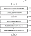
Certain aspects of the systems and methods described herein relate to the secure and timely transmission of process data from a process control system of a process plant to a remote computing device. The system and method may allow secure access to any process data within the process control system in real time via a mobile server that receives the process data from a data server, which in turn obtains the process data from the process control system in real time as data values are generated or received by a controller within the process control system.
In an embodiment, a method of securely subscribing to a remote computing device to obtain process data from a process control system of a process plant includes: the method includes receiving, at a mobile server, configuration data indicative of a configuration of a process control system from a data server via a first network, and establishing, by the mobile server, a communication connection with a remote computing device via a second network. The method also includes receiving, at the mobile server, an indication from a remote computing device via a second network requesting a view list of process data associated with the process control system. The process data corresponds to the available data indicated by the configuration data. The method further comprises the following steps: the method includes receiving, at the mobile server from the data server via the first network, a polling request for a list of data to be sent from the data server to the mobile server, determining, by the mobile server, the list of data based at least in part on the view list, and sending, in response to the polling request, the list of data from the mobile server to the data server via the first network. In addition, the method comprises: the method includes receiving, at a mobile server, a plurality of data values associated with a list of data from a data server via a first network, and sending, from the mobile server to a remote computing device via a second network, a view set containing at least some of the plurality of data values corresponding to a list of views associated with the remote computing device.
In other embodiments, a computer system for communicating process data from a process control system of a process plant to a remote computing device, includes: the system includes one or more processors, one or more communication units configured to send and receive data via a first network and a second network, and memory storing executable instructions that, when executed by the one or more processors, cause a computer system to execute a plurality of modules. The executed modules include one or more scanners interfacing with one or more communication units to enable communication with a data server via a first network. In particular, the scanner communicates by: the method includes receiving data from a data server, identifying a polling request in the data received from the data server, and sending a list of requests to the data server in response to the polling request. The module also includes a data stream processor that determines a set of process data values from the data received by the data server, the set of process data values corresponding to view list data to be transmitted to the remote computing device. Another included module is an Application Program Interface (API) that interfaces with one or more communication units to enable communication with a remote computing device via a second network by sending a set of process data values to the remote computing device.
Drawings
The features and advantages of the methods, apparatus, and systems described herein will be best understood with reference to the following detailed description and accompanying drawings, in which:
FIG. 1A is a block diagram of an example process control environment according to the present description;
FIG. 1B is a flow diagram illustrating an example process in a process control environment;
FIG. 1C is a block diagram of individual units within the exemplary process of FIG. 1B;
FIG. 1D illustrates individual process control entities of the units of FIG. 1C;
FIG. 1E is a block diagram illustrating a production flow by another one of the process control entities in the example process of FIG. 1B;
FIG. 1F depicts two exemplary display graphics that may be displayed in accordance with the present description;
FIG. 1G depicts an exemplary watch list that may be displayed in accordance with the present description;
FIG. 1H depicts an exemplary display showing data related to a particular item on the watch list in FIG. 1G;
FIG. 1I depicts an exemplary alert list display according to the present description;
FIG. 1J depicts a display that may be generated for a particular alarm in the alarm list of FIG. 1I;
FIG. 1K depicts an alternative display of the information in FIG. 1H, which may be shown when the device is rotated to a landscape orientation;
FIG. 1L depicts a block diagram that shows an overall architecture of a system for mobile information distribution in a process control environment, according to the present description;
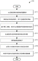
FIG. 2A is a flow diagram of an example data list configuration method in a process control system of a process plant;
FIG. 2B is a flow diagram of an example configuration data retrieval method in a process control system of a process plant;
FIG. 2C is a flow diagram of an example data subscription method in a process control system of a process plant;
FIG. 2D is a sequence diagram of an example data subscription communication sequence in a process control system of a process plant;
FIG. 2E is a flow diagram of an example data server communication method in a process control system of a process plant;
FIG. 2F is a sequence diagram of an example data server communication sequence in a process control system of a process plant;
FIG. 2G is a flow diagram of an example mobile server communication method in a process control system of a process plant;
FIG. 2H is a sequence diagram of an example mobile server communication sequence in a process control system of a process plant;
FIG. 2I is a sequence diagram of an example view list subscription sequence in a process control system of a process plant;
FIG. 2J is a block diagram of an example data server within a process control system of a process plant;
FIG. 2K is a block diagram of an example mobile server in a process control system of a process plant;
FIG. 2L is a block diagram of an example mobile server internal communication architecture in a process control system of a process plant;
FIG. 2M is a flow diagram of an example alarm notification method in a process control system of a process plant;
FIG. 2N is a sequence diagram of an example alarm transmission sequence in a process control system of a process plant;
FIG. 2O is a block diagram of an example alarm notification architecture in a process control system of a process plant;
FIG. 2P is a flow diagram of an example alarm response method in a process control system of a process plant;
FIG. 2Q is a block diagram of an exemplary web client embodiment in accordance with the systems and methods described herein;
FIG. 3A is a signal diagram of an exemplary GUI generation sequence executing on a mobile computing device;
FIG. 3B is an exemplary representation of a list GUI executing on a mobile computing device;
FIG. 3C is an exemplary representation of a list GUI executing on a mobile computing device;
FIG. 3D is an exemplary representation of a watch list GUI executing on a mobile computing device;
FIG. 3E is an exemplary representation of a watch list item GUI executing on a mobile computing device;
FIG. 3F is an exemplary representation of a watch list item GUI executing on a mobile computing device;
FIG. 3G is an exemplary representation of an alert list GUI executing on a mobile computing device;
FIG. 3H is an exemplary representation of an alert item GUI executing on a mobile computing device;
FIG. 3I is an exemplary representation of steps in assembling a view of a list item via a watch list GUI executing on a mobile computing device;
FIG. 3J is an exemplary representation of steps in assembling a view of a list item via a watch list GUI executing on a mobile computing device;
FIG. 3K is an exemplary representation of steps in assembling a view of a list item via a watch list GUI executing on a mobile computing device;
FIG. 3L is an exemplary representation of steps in assembling a view of a list item via a watch list GUI executing on a mobile computing device;
FIG. 3M is an exemplary representation of steps in a process of combined viewing of list items via a watch list GUI executing on a mobile computing device;
FIG. 3N is a flow diagram of an exemplary list configuration method performed by a mobile computing device;
FIG. 3P is an exemplary representation of a selection interface executing on a mobile computing device;
FIG. 3Q is an exemplary representation of a retrieval interface executing on a mobile computing device;
FIG. 3R is an exemplary representation of a filter interface executing on a mobile computing device;
FIG. 3S is a flow diagram of an exemplary user access configuration method performed by a mobile computing device; and
fig. 3T is an exemplary representation of a user access interface executing on a mobile computing device.
Detailed Description
As described above, known distributed process control systems lack the ability for operators, maintenance personnel, and other personnel associated with the process control system to maintain context awareness while located remotely from the operator workstation and/or from the physical location of the process plant. Thus, plant personnel cannot observe the operation of the process control system and the process plant unless the plant personnel are physically present. Since process plants are typically operated in multiple shifts, the observation and operation of a process plant is typically switched multiple times per day. While the plant personnel for a particular shift may leave notes on these personnel for the next shift, these shift changes result in discontinuities in the operation and management of the process and equipment, which may have a detrimental effect on product quality, plant efficiency, maintenance, environmental safety, compliance regulations, and other aspects of process plant management. Embodiments of the systems, devices, and methods for mobile information distribution described herein may mitigate many of the discontinuities and problems associated therewith resulting from such shift changes, provide increased situational awareness for plant personnel, and make additional advantages apparent from the following disclosure.
FIG. 1A illustrates an example process plant network 10 that includes a mobile services infrastructure 12 for supporting a plurality of mobile devices 14, which are not necessarily located at a process plant site, but have access to data associated with a process plant. As will be described in detail herein, the mobile services infrastructure 12 facilitates the real-time transfer of any of the process plant data available within the process control device network 10 to the mobile devices 14 while maintaining the security of the process plant network 10. Each of the mobile devices 14 includes, among other elements, an application 16 executable by the mobile device 14 to allow a user to interact with process plant data via a Graphical User Interface (GUI) 18.
Generally, plant personnel use one or more applications 20 to oversee or control the operation of the process plant 10 and a distributed control system 22 implemented within the process plant 10. The viewing or monitoring application 20 typically includes a user interface application that uses a variety of different displays to graphically depict process graphics to each of the operators and maintenance technicians and/or other users at workstations, such as the workstations 30 and 32.
The process plant environment of FIG. 1A also includes a graphic configuration system 34. The graphic configuration system 34 generally facilitates the creation of control and monitoring schemes, including graphic displays, for controlling a process plant. The graphic configuration system 34 may include, for example, a configuration editor 35, which configuration editor 35 may be used to store control modules and control module templates, graphic displays and templates, and other aspects of the control system in a library, and the configuration editor 35 may then be used to create instances or usages that are actually performed in the control of the process plant during operation of the plant 10 by downloading instances of the control modules to the controllers, or by executing instances of the graphic displays in user displays presented to, for example, operators and maintenance personnel. Of course, the graphics configuration system 34, the configuration editor 35, and each of the various control modules, templates, and graphical displays may be stored in tangible computer-readable memory or media and executed on one or more processors to perform the functions described herein.
Generally, the distributed process control system 22 illustrated in FIG. 1A has one or more controllers 40 that are each connected to one or more field devices 44 and 46 (which may be smart devices) via an input/output (I/O) device or card 48, which may be, for example, a Fieldbus interface, a Profibus interface, a HART interface, a standard 4-20ma interface, or the like. The controller 40 is also coupled to one or more host or operator workstations 30-32 via a data highway 54 (which may be, for example, an Ethernet link). A process data database 58 may be coupled to the data highway 54 and operates to collect and store process variables, process parameters, status and other data associated with the controllers, field devices and any other devices within the plant 10. During operation of the process plant 10, the process data database 58 may receive process data from the controller 40 and indirectly from the field devices 44-46 via the data highway 54.
The configuration database 60 stores the current configuration of the distributed control system 22 within the plant 10 as it is downloaded to and stored within the controllers 40 and field devices 44, 46. The configuration database 60 stores process control functions defining one or more control strategies for the distributed control system 22, configuration parameters for the devices 44, 46, assignments of the devices 44, 46 to the process control functions, and other configuration data associated with the process plant 10. The configuration database 60 may additionally store graphical objects or user displays and configuration data associated with such objects or displays, as described in more detail herein, to provide various graphical representations of elements within the process plant 10. Some of the stored graphical objects may correspond to process control functions (e.g., process graphics developed for a certain PID loop) and other graphical objects may be device specific (e.g., graphics corresponding to pressure sensors).
The data historian 62 (another database) stores a process of events, alarms, notes, and actions taken by the operator. Events, alarms, and comments may relate to individual devices (e.g., valves, transmitters), communication links (e.g., wired Fieldbus segments, WirelessHART communication links), or process control functions (e.g., PI control loops for maintaining a desired temperature set point). In addition, the knowledge repository 64 stores references, operator log entries, help topics, or links to these and other documents that may be found useful by operators and maintenance technicians when overseeing the process plant 10. Still further, the user database 66 stores information about users (such as operators and maintenance technicians). For each user, the user database 66 may store, for example, his or her organizational role, the control areas of the user, the areas within the process plant 10 with which the user is associated, work team associations, safety information, system privileges, shift information, and the like.
Each of databases 58-66 may be any desired type of data storage or collection unit having any desired type of memory and any desired or known software, hardware, or firmware for storing data. Of course, the databases 58-66 need not reside in separate physical devices. Thus, in some embodiments, some of the databases 58-66 may be implemented on a shared data processor and memory. In general, it is also possible to use more or fewer databases to store data collectively stored and managed by databases 58-66 in the exemplary system of FIG. 1A.
While the controller 40, I/O cards 48 and field devices 44, 46 are typically located and distributed throughout the sometimes harsh plant environment, the operator workstations 30 and 32 and the databases 58-66 are typically located in control rooms or other less harsh environments easily assessable by controllers, maintenance personnel and various other plant personnel. However, in some cases, handheld devices coupled to the data highway 54 may be used to perform these functions, and these handheld devices are typically carried around in the factory. And in some cases, such hand-held devices, operator workstations, and other display devices may be connected to the DCS 22 via a wireless communication connection. The handheld device differs from the mobile device 14 in that the mobile device does not necessarily reside in a process plant site and does not need to be directly coupled (via wired or wireless means) to the data highway 54.
As is known, each of the controllers 40 (which may be, for example, DeltaV sold by Emerson Process management, Inc.) TM Controller) stores and executes a controller application that implements a control strategy using any number of different, independently implemented control modules or blocks 70. Control mould Each of the blocks 70 may be comprised of what are commonly referred to as function blocks, wherein each function block is a part or a subroutine of an overall control routine and operates in conjunction with other function blocks (via communications called links) to implement process control loops within the process plant 10. As is well known, function blocks, which may be objects in an object oriented programming protocol, typically perform one of an input function, such as that associated with a transmitter, a sensor or other process parameter measurement device, a control function, such as that associated with a control routine that performs PID, fuzzy logic, etc. control, or an output function, which controls the operation of some device, such as a valve, to perform some physical function within the process plant 10. Of course, hybrid and other types of complex function blocks exist, such as Model Predictive Controllers (MPCs), optimizers, and so on. While the Fieldbus protocol and the DeltaV system protocol use control modules and function blocks designed and implemented in an object oriented programming protocol, the control modules may be designed using any desired control programming scheme, including, for example, sequential function blocks, ladder logic, etc., and are not limited to being designed and implemented using function blocks or any other particular programming technique. Each of the controllers 40 may also support sales by Emerson Process management  A suite is applied and predictive intelligence can be used to improve the availability and performance of production assets including mechanical equipment, electrical systems, process equipment, instrumentation, non-intelligent and
 intelligent field devices 44, 46, etc.
As depicted, the DCS 22 includes one or more of the controllers 40 communicatively coupled to the workstation(s) 30, 32 in the control room. The controller 40 automates the control of the field devices 44, 46 in the process area by executing process control strategies executed via the workstations 30, 32. An example process strategy involves measuring pressure using a pressure sensor field device and automatically sending a command to a valve positioner to open or close a flow valve based on the pressure measurement. The I/O card 48 converts information received from the field devices 44, 46 into a format compatible with the controller 40 and converts information from the controller 40 into a format compatible with the field devices 44, 46.
Through the I/O card 48, the controller 40 may communicate with the field devices 44, 46 according to a control module 70 that has been downloaded to the controller 40. Control module 70 is programmed using configuration system 34. In configuring the system 34, an engineer may create the control module 70 by, for example, instantiating one or more function blocks. As an example, the configuration engineer may instantiate an AI function block to receive analog input from one of the field devices 44, 46, where the AI function block may receive various values (e.g., signal values, alarm upper and lower limits, signal states, etc.) associated with the analog output of the field devices 44, 46. The AI function block may output a corresponding signal to another function block (e.g., a proportional-integral-derivative (PID) control function block, a custom function block, a display module, etc.). Once the AI function block is instantiated, associating the function block with the unique device tags associated with the field devices 44, 46 will cause the function block, once downloaded to the controller 40, to cooperate with the appropriate I/O card 48 to process information from the correct field device 44, 46.
In the plant network 10 shown in FIG. 1A, the field devices 44, 46 connected to the controllers 40 may be standard 4-20ma devices, and may be smart field devices (such as a smart field device including a processor and a memory) Profibus, or
 Fieldbus field devices) or may be any other desired type of device. Some of these devices, such as Fieldbus field devices (labeled with
 reference number 46 in FIG. 1A), may store and execute modules or sub-modules (such as function blocks) associated with the control strategy implemented in the controllers 40, or modules or sub-modules (such as data collection, trending, alarming, calibration, etc.) that perform other actions within the process plant (such as data collection, trending, alarming, calibration, etc.)Such as a function block). As is well known, the function blocks 72 shown in FIG. 1A as being disposed in two different ones of the Fieldbus field devices 46 may be executed in conjunction with the control modules 70 within the execution controller 40 to implement process control. Of course, the field devices 44, 46 may be any type of device (such as sensors, valves, transmitters, positioners, etc.) and the I/O device 48 may be any type of I/O device conforming to any desired communication or controller protocol, such as HART, Fieldbus, Profibus, etc.
With continued reference to FIG. 1A, the workstations 30 and 32 may include a variety of applications for a variety of different functions performed by personnel within the plant 10. Each of the workstations 30 and 32 includes a memory 80 and a processor 82, the memory 80 storing various applications, programs, data structures, etc., and the processor 82 may be used to execute any of the applications stored in the memory 80. In the example illustrated in FIG. 1A, in addition to the display and viewing application 20, the workstation 30 includes one or more process controller configuration applications 84 that may include, for example, a control module creation application, an operator interface application, and other data structures that may be accessed by any authorized configuration engineer to create and download control routines or modules (such as the control modules 70 and 72) to the various controllers 40 and devices 46 of the plant 10. The configuration application 84 also includes a display or graphic configuration system 34 having a configuration editor 35 that can be used to create the control module 70.
In general terms, the viewing application 20 allows an operator to view display modules configured to provide specific information regarding the operation of a particular area of the process plant 10, and the viewing application 20 allows an operator to control the operation of the process plant 10 based on the information on the display modules. Display modules are presented on the workstations 30, 32 and include real-time process data received from the controller 40 and the field devices 44, 46. As used herein, "real-time" communication of data refers to electronic communication of data through an electronic communication network with ordinary delays for processing, routing, and transmission, without intentionally introducing additional non-trivial delays. In some embodiments, a slight delay of less than five seconds (preferably less than two seconds) may be introduced to reduce network congestion when transmitting data in real time. The display modules may be any type of interface that enables, for example, an operator or other user to manipulate data values (e.g., perform reads or writes) to monitor or change the operation of the field devices 44, 46, the control modules 70 and function blocks 72, and the DCS 22 and the process plant 10 as a whole. The display modules may be stored in the memory 80 of the workstations 30, 32 and may also be stored in the configuration database 60.
In some embodiments, the control module 70 and the display module may be part of a configuration file 74 in the configuration database 60. That is, the control module 70 may be stored in the configuration file 74 with the display module or separately from the display module. In any case, the configuration file 74 typically stores the entire configuration of the DCS 22, including devices, device tags, friendly names, data formatting information (e.g., scaling information, unit types, etc.), which variables are associated with each control loop, the defined control strategies, and so forth. As previously indicated, the configuration file 74 may also be downloaded to the controller 40 to implement the control strategy defined in the configuration file 74.
As will be understood, the process plant 10 may include hundreds, thousands, or even thousands of signals, outputs from transmitters (i.e., sensors) on hundreds or thousands of field devices 44, 46, and/or inputs to those field devices 44, 46 to cause the field devices 44, 46 to perform control functions in accordance with control strategies programmed into the control module 70. The plant 10 may be divided into different areas, multiple of which may be controlled by a single controller 40, each of which may be controlled by a single controller or multiple controllers 40, or some combination. In any case, the field devices 44, 46 that make up the process plant 10 may be individually replicated multiple times within the process plant 10 (e.g., there may be multiple valves of any type, multiple pumps, multiple heaters, multiple tanks, etc.). The field devices 44, 46 may also be combined into functional groups within a physical area ("process area"), where the field devices 44, 46 within the process area perform specific portions of the overall process. For example, a particular process area may have equipment for generating steam for other parts of the process. Within a process area, there may be duplicate blocks or groups of equipment ("process elements") that share similar structure and functionality. As an example, a process unit in a steam generating process zone may include a boiler and a turbine generator, and a process zone may include multiple instances of the process unit.
As an example, FIG. 1B depicts a flow diagram 100 showing a process for converting crude oil to other fuel products. At the entry point to the refining process, crude unit 102 separates the components and distributes the components for further downstream processing by other units. Each of the units may include various equipment such as pumps, compressors, heat exchangers, reactors, tanks, separation and distillation columns, as well as various valves, transmitters, pumps, and the like. Many of the units may include general purpose processing equipment. For example, the heaters may be used in different ones of the cells.
Referring to FIG. 1C, a block diagram of a crude unit 102 is depicted, the crude unit 102 including various field devices. Although fig. 1C depicts the desalter 104, fired heater 106, fractionator 108, pump 110, and vessels 112, 114, the crude unit 102 also includes other field devices, such as temperature, level, and pressure transducers, valves, and the like, which are not shown in fig. 1C. Each of the field devices, each group of devices, each process unit and/or each process area may have a corresponding display graphic used in the display module to represent it to an operator during operation of the process plant 10 and to include specific information for its operation. For example, as depicted in FIG. 1D, fired heater 106 may be represented in display module 116 with a limited set of parameters.
In fig. 1D, fired heater 106 is depicted as having six parameters. Although of course these parameters will vary for each of the various blocks of the equipment, and in some cases for different uses of the equipment (e.g., the parameters included in the fired heater 106 used in the crude unit 102 may differ from those included in the fired heater used in the diesel hydrotreater), the parameters will varyThe parameters depicted in the display module 116 include O in the flue gas (118, 120, respectively) 2 And NO X Level, outlet temperature 122, process fluid flow rate 124, fuel gas pressure 126, and vent pressure 128.
As another example, and referring back to fig. 1B, diesel fuel output from the crude unit 102 flows to the hydrocracker 103. The components of the diesel hydrocracker 103 are depicted in block diagram 130 in FIG. 1E and include a feed system 132, a bank of heaters and reactors 134, a stripper 136, and a gas plant 138. Of course, each of the components shown in FIG. 1E may be made up of several (or many) subcomponents. For example, the set of heaters and reactor 134 may comprise a single reactor or a plurality of reactors. Thus, as depicted in fig. 1F, the display graphic corresponding to reactor 134 may include a single reactor or multiple reactors, and the display graphic may be displayed differently depending on whether one or multiple reactors are included. In FIG. 1F, display graphic 140 depicts a single reactor, while display graphic 142 depicts multiple reactors. Associated parameters for displaying each of the graphics 140 and 142 are also depicted, and it should be understood that may differ depending on the particular arrangement and use of the depicted equipment.
Personnel in an oil refinery or any process plant are generally not responsible for monitoring or controlling the entire process plant. Instead, the personnel have a different "scope of responsibility". With reference to the exemplary refining process described above, for example, a particular operator may be responsible for a crude unit and one of several diesel hydrotreaters. Other operators may be responsible for other groups of the same equipment (e.g., another crude unit in the same process area, a crude unit in another process area, etc.), some operators may be responsible for different groups of equipment (e.g., a naphtha hydrotreater), and other operators may be responsible for monitoring higher-level processes (e.g., monitoring characteristics of one or more of the entire refinery process or output products). Each operator may view, monitor, and/or manipulate different display modules depending on the operator's scope of responsibility. Operators having similar responsibility ranges (e.g., two operators each responsible for a crude unit) can see the same viewing display module (each showing data for the crude unit each operator is responsible for), while other operators can see different display modules adapted (i.e., designed or configured) to allow monitoring and/or manipulation of parameters, equipment and processes corresponding to each operator's responsibility range. Other personnel (e.g., non-operators) may be responsible for environmental operations in the process plant and may be interested only in environmental parameters, alarms, and alarms associated with all or a subset of the equipment in the process plant, which may or may not correspond to equipment within one of the operator's areas of responsibility.
The data and displays available in real time to operators and other personnel within the process plant, including real time process variables and parameters, alarms, warnings, alerts, configuration information (e.g., from configuration files 74), control modules 70, display modules, batch information (for batch processes), etc., are collectively referred to throughout this specification as "process-level data," and may include all data stored, processed, or transmitted by the controller 40. Process level data is valuable to operators and, of course, maintenance and other service personnel who may need or desire to monitor the real-time status of all or part of the process.
In the embodiments described herein, personnel may access process-level data via mobile device 14 (and in some embodiments additional data is further described elsewhere in the specification). This may be useful, for example, when the operator desires to monitor equipment within his responsibility during a phase when he is not working (e.g., during another shift), in order to keep monitoring for specific issues that have occurred before, or to simply maintain a degree of situational awareness during shift changes for continuous purposes (i.e., to know what occurred during the previous shift when returning to her shift). At the same time, maintenance personnel may wish to be alerted of a problem that will need to be resolved when they return to the process plant. Further, personnel at the process plant site (e.g., "on-duty" operators) may wish to collaborate with colleagues currently not at the site to receive assistance in diagnosing and/or addressing an abnormal situation in the process plant, and having access to process-level data when not physically present at the process plant may facilitate such collaboration. Of course, there are many other reasons why plant personnel would benefit from the availability of plant-level data on the mobile device 14.
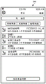
In general, the contemplated embodiments facilitate access to plant level data via mobile device 14 by allowing a user of mobile device 14 to configure a view list. The view list may include lists such as, for example and without limitation, a watch list, an alarm list, a lot list, a calculation list, a system diagnostics list, an equipment alarms list, a Key Performance Indicator (KPI) list, a decision support list, and other derivatives of the "list" concept. Fig. 1G depicts an exemplary watchlist 144 for diesel hydrotreater 103 (labeled "DHT 1"). The watchlist of diesel hydrotreater "DHT 1" includes various items 146 that can be customized by a user of mobile device 14, and the order of the items in list 144 can also be customized by the user (as described below).
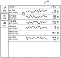
From the list 144, the user may select one of the watch list items to retrieve and view other information about that item, including historical values and other associated parameters such as labels, module names, friendly names, information source paths, and other information that may depend on the item selected from the watch list, as shown in view 148 in FIG. 1H. For example, in the case of a control loop, the items may include the process variable itself, its set point, output, and scale, in addition to the alarm and/or abnormal condition associated with the process value. As will be described herein, most of the displayed information and the manner in which it is displayed may be customized by the user.
As the user may do in the process plant (e.g., from the operator workstations 30, 32) — the user may quickly navigate from the displayed data to the relevant data. For example, by clicking on an alarm, the user can navigate to the alarm list 150 and/or the alarm view 152 (see FIG. 1J) as shown in FIG. 1I, from which alarm view 152 the user can view details of the alarm, such as the alarm name, description, time and date of the alarm, response time, functional classification, trends associated with the process value that triggered the alarm, suggested corrective action, and the like. This is similar to the way an operator at a workstation 30, 32 can interact with an alarm by clicking on it to view the associated data.
The system may also provide the user with a list of key decisions that need attention. These lists may relate to operations, planning, maintenance, asset management, etc. The priority of the decision may reflect a fast change and cannot simply be specified in an early condition (commonly referred to as unstructured and semi-structured decision problems). The decision support system may be fully computerized, human, or a combination of both.
In embodiments, additional information may be made available by rotating mobile device 14 to a landscape orientation as depicted in FIG. 1K, and the information may be navigated and viewed in more or less detail by zooming in/out using touch gestures.
Other features will be described in detail with reference to the infrastructure and system embodiments.
System architecture
Turning now to FIG. 1L, a block diagram illustrates an overall architecture 152 of a system for mobile information distribution in a process control environment. The architecture is generally divided into three levels: a factory/process level 154, a data service level 156, and a mobile service level 158 that includes four to six different networks in total. The plant/process level 154 includes a field network (not shown) that couples the controller 40 to the field devices 44, 46, and a control network (depicted in FIG. 1A as the data highway 54) that couples the controller 40 to the workstations 30, 32, the databases 58-66, and other components within the process control plant 10. The plant/process level 154 may optionally include an intermediary network 160 that may couple the control network 54 to other service level applications. The plant/process level 154 is coupled to the data service level 156 through a network 162. The data service level 156 is coupled to the mobile service level 158 through a network 164. The mobile service level 158 includes one or more other networks, such as the internet and/or a mobile telephony/data network. Each of the layers 154, 156, 158, and indeed each of the networks, may be isolated from the other networks by hardware and/or software firewalls, among other security measures. The layered architecture allows isolation between the various networks 54, 160, 162, 164, etc.
At the plant/process level 154, a communicator interface 170 provides an interface between the controllers 40 and the process plant 10 on one side and the data service level 156 on the other side. Although a single communicator interface 170 is depicted in FIG. 1L as communicating with a single controller 40 (and, therefore, a single process plant 10), the communicator interface 170 may communicate with multiple controllers 40 controlling a single process plant, wherein various areas of the process plant 10 are controlled by separate controllers 40. It is also contemplated that, in an embodiment, multiple process control systems 10 may be coupled to the data service level 156 and the mobile service level 158 via multiple communicator interfaces 170. In a particular embodiment, a communicator interface 170 is coupled to each process control system 10 and a group of communicator interfaces 170 are coupled to the data service level 156. It is also contemplated that multiple control systems may be physically located at different locations (e.g., at different chemical plants).
The communicator interface 170 may be part of a larger portal 171, the portal 171 providing an overall interface to the data service level 156 and the mobile service level 158, respectively. The portal 171 may include functionality such as facilitating configuration of user information, device and system information, and software/hardware licenses.
Further, in the factory/process level 154, a file interface 172 is used to transfer the configuration file 74 to the data service level 156. In certain embodiments, the file interface 172 is part of a dedicated one of the workstations 30, 32, the workstations 30, 32 being used to configure the process plant 10 and including the graphic configuration system 34, the configuration editor 35, and the like. In other embodiments, the file interface 172 may be part of the communicator interface 170. In any case, the file interface 172 is coupled to the data service level 156 and communicates configuration data for the process plant to the data service level 156.
At data service level 156, data server 174 includes a plurality of different data services 176 that collectively receive data from communication interface 170 and file interface 172 and communicate the received data to mobile service level 158. Included in the data received from the factory/process level 154 and transmitted to the mobile services level 158 are: alarms, process parameters, diagnostics, historical data, and configuration data. Each data service 176 may also be used to index the configuration files 74 received from the file interface 172. The indexing operations may include indexing specific information, such as module parameters and module hierarchies, to support specific retrieval capabilities, which may allow a user to retrieve parameter names, device tags, alarms, or other data for the process plant 10.
The mobile server 178 is the core of the mobile service level 158. The mobility server 178 supports connections to the mobile device 14, supports configuration of various lists (e.g., alert lists, watch lists, etc.) to which the mobile device 14 subscribes, provides retrieval capabilities, and manages mobility notifications. The mobile server 178 is also responsible for creating and maintaining subscriptions to various data from the data service 176. The mobile server 178 is coupled to the mobile device 14 by any of a variety of wireless data technologies, which may include Wi-Fi (i.e., a protocol in the IEEE 802.11 protocol suite) and/or mobile ("cellular") infrastructure using any of a variety of data services available now or in the future, including but not limited to LTE services, some or all of which may utilize the internet 180.
The mobile device 14 may comprise a mobile device running the Android mobile operating system developed by Google (Google), a mobile device running the iOS mobile operating system developed by Apple (Apple), or any other operating system now known or developed in the future. Those familiar with the use of these services will readily appreciate that for mobile devices 14 running android and/or iOS mobile operating systems, notifications may be delivered to the mobile device 14 via the apple or google notification service 182. The mobile server 178 facilitates configuration of notification services at a system level and/or a user level.
With regard to configuration of mobile information distribution, the mobile server 178 provides certain configuration services via a mobile device interface that is native to the mobile device 14. The mobile server 178 also provides configuration options via a web page (i.e., using a web browser). As will be described later, the various alarm lists and watchlists can be configured via a web interface using search (i.e., searching the index data of configuration files 74) and/or filters, and utilizing system-level information, function classifications, alarm priorities, alarm categories, and the like. Additional details regarding the system configuration will be provided later in this description.
The availability of configuration data at the mobile service level 158 can be used to provide an especially rich mobile environment for the end user, since the system has access not only to data but also to relationships between data. By way of example, the mobile server 178 has contextual access to data and data types through configuration data from the configuration file 74, rather than merely having a status of an alarm (e.g., active) or a status of a parameter value (e.g., normal, high, low, etc.). Thus, the system may determine that a particular activated alarm is the result of a parameter status of "high" and that the parameter status is "high" because the parameter data value exceeds a particular limit. As a result of the rich contextual information available to the mobile server 178, for example, the user interface may be operable to present data in context — either real-time data and historical portrayal alerts, or process variables may be portrayed with current and historical setpoint values and optional related module relationships, which may allow a user to navigate from one data to another related data based on relationships between process control devices, function blocks, etc.
Process data configuration and communication
As described more fully elsewhere herein, systems and methods for providing process data associated with a process plant to a remote computing device are disclosed. The process data may include data from the controller 40 via the communicator interface 170, data from the process database 58, or data otherwise communicated via the process plant network 10. In certain embodiments, the process data may include or may be augmented by adding additional data about the process plant, such as data stored in the data historian 62, the knowledge store 64, or data received from a specialized server 186. The additional data may include historical data of past operations of the process plant, summary data associated with past or current operations of the plant, batch data associated with batch runs or scheduling of the process plant, scheduling data associated with plant operations, maintenance data associated with the process plant, business data related to the efficiency or profit of the process plant, or other information associated with the operations of the process plant. The process data (and, if applicable, additional data) may be generated from or obtained from information generated by components in a process control system that controls the operation of some or all of the process plant.
The process data (and any additional data) is provided to the remote computing devices through the data server 174 and the mobile server 178. The data server 174 may execute a data service 176 to obtain data via the process control network 162 and communicate with a mobile server 178 via the remote access network 164. These networks 162 and 164 may be separated by an existing firewall 166, thereby allowing secure communications using existing network architecture. To further secure network communications and protect the process control system from unauthorized access, in a particularly preferred embodiment, the data server 174 may only accept the requested data list from the mobile server 178. In such a preferred embodiment, the data server 174 may send a polling request for these lists to the mobile server 178. In response to the polling request, the mobile server 178 may send the requested data list to the data server 174. In further embodiments, the data server 174 may be configured to accept only the requested data list from the mobile server 178, and such list may be accepted only in response to a polling request. For example, the data server 174 may be configured to accept the requested data list from the known mobile server 178 only during a predetermined period of time after each polling request is transmitted to the mobile server 178. The mobility server 178 may likewise be configured to send only a list of data requests to the data server 174, and only in response to receiving a polling request from the data server 174.
Based on the received list of requested data, the data server 174 may obtain process data from the process control system via the process control network 162. This may include requesting or subscribing to a data stream from one or more components within the process control system, such as process data associated with a particular controller 40 or field device 46, 48. In certain embodiments, the process data obtained by the data server 174 or transmitted to the mobile server 178 may include only L1 data from the process control system. As used herein, "L1 data" refers to process data (e.g., display graphics and process entity visualizations) generated or used by or within the workstations 30, 32, controllers 40, or field devices 44-46 of a process control system used to control the operation of a process plant. In other embodiments, additional data may be included. The data server 174 may also obtain data from additional components through the process control network 10 if additional data is requested in the requested data list. Such additional data may include, by way of example and not limitation, one or more of the following: key Performance Indicators (KPIs), batch information, maintenance information, efficiency information, knowledge base information about equipment or conditions within a process plant, decision support information, or scheduling information. Thus, the data server 174 obtains a plurality of data values from the process control system. The data values may be indicative of specific process parameter values, such as sensor output values, process flow rates, material input or output values, equipment operating state values, derived or inferred values, control module parameter values, or any other value of a type of data generated by or maintained within the process control system, including graphical display elements that may be used in the operator workstations 30, 32. When a data value is obtained from the process control system, the data server 174 may then identify or select the received data value corresponding to the requested data indicated in the list to be sent to the mobile server 178. The data server 174 then transmits the identified data value to the mobility server 178 via the remote access network 164. In a preferred embodiment, the data server 174 receives the requested process data values and transmits the requested process data values to the mobile server 178 in substantially real time as the requested process data values become available (i.e., with only a modest communication delay when generating the process data values within the process control system). Thus, the data server 174 may receive multiple data streams from entities within the process control system and may also send one or more data streams to the mobile server 178 to establish a real-time data subscription.
When the mobile server 178 receives the requested data value from the data server 174, the mobile server 178 also identifies one or more remote computing devices to receive the set of one or more data values. The mobile server 178 then transmits the set of data values to the corresponding remote computing device via a mobile network, which may include the remote access network 164, the internet 180, or other networks that facilitate communication between the mobile server 178 and the remote computing device. In some embodiments, at least a portion of the mobile network may be an external network (e.g., the Internet 180) that is not associated with the process control system or the process plant. In a particularly preferred embodiment, the mobile server 178 transmits the set of data values to the remote computing device in substantially real time as the data values are received from the data server 174. Thus, the remote computing device may receive a data stream of process data from the process control system. The remote computing device may be the mobile device 14 described above, such as a smartphone, tablet computer, wearable computing device such as a smartwatch, or other highly mobile computing device. The remote computing device may also include a notebook, netbook, desktop, or similar computer located remotely from the process plant and in communication with the mobile server 178 via the web client 198. In any case, the remote computing device communicates with the mobile server 178 via a mobile network to obtain process data values from the process control system. In a particularly preferred embodiment, the remote access device only receives process data from the mobile server 178 and does not otherwise communicate with the process control network. Thus, in such an embodiment, the remote access device may not be able to access the process control network 10 or the process control system except in the limited manner described herein via the mobile server 178 and the data server 174.
This configuration increases the security of the process control system by limiting access to remote computing devices to receiving requested data via the mobile server 178, where the mobile server 178 itself only receives data from the data server 174. These additional protective measures are important in process control systems because remote access to the controller 40 or other components of the process control system (particularly remote controls) by unauthorized users presents a serious, potentially fatal, hazard. Significant damage and destruction to the process plant may occur if an unauthorized user gains control of equipment in the process plant. Even without control, unauthorized users may use non-public information about the operation of the process plant (which may include business secrets) and thus commercially compromise plant operators. In conventional process plants, these problems are partially addressed by physical security measures, such as restricting physical access to the workstations 30, 32 and other sensitive equipment. However, in the case of remote access, new ways of protecting the process plant beyond its physical boundaries are needed. While security may be achieved by limiting or eliminating access to process data from a remote location, such limitations will prevent information about the plant from reaching process plant personnel that require access to ensure proper operation of the plant.
To address both issues simultaneously, the systems and methods described herein allow remote computing devices to access process data via a mobile server 178 in communication with a data server 174. To obtain the data, the remote computing device requests the data values associated with the data list from the mobile server 178. In response to the polling request, the mobile server 178 then sends one or more lists of requested data to the data server 174. In some embodiments, the mobile server 178 may generate a combined list of requested data from a list of data received from a plurality of remote access devices. When data values are received from the data server 174, the mobile server 178 may then determine, based on the data list, which of the remote computing devices have requested data corresponding to the received data values. In any case, the mobile server 178 identifies the data values received from the data server 174 and transmits the appropriate data values to one or more remote computing devices via a mobile network. To identify the appropriate data values to transmit to each remote computing device, mobile server 178 uses a data list associated with each remote computing device.
The data list may be received from the remote computing device or may be identified by a data list indicator received from the remote computing device. For example, the remote computing device may request data values associated with a predetermined data list stored in the memory of the mobile server 178 by sending an indicator of the predetermined data list to the mobile server 178. Such a request may be automatically generated by the remote computing device in certain states, or the request may be generated upon the occurrence of an action by a user of the remote computing device. The indicated data list may be a data list previously established by a user of the remote computing device or may be a shared data list available to multiple remote access device users. The data list may be a watch list indicating process parameters observed in the process control system, a view list associated with a data view (corresponding in some but not all embodiments to an operator view available on a workstation) for display on a remote computing device, an alarm list indicating alarms for monitoring, or other types of data received at a remote computing device. Each list may include a plurality of entries identifying data sources (or additional data sources associated with additional data) within the process control system. The entries may be associated with entities within a process control system that generate or otherwise provide process or additional data associated with a process plant, such as sensors, valves, control modules, function blocks, controllers, equipment units, process units, or areas. The entry may likewise be associated with a process parameter associated with the operation of the process plant or a condition within the process plant by the process control system. The entries may be hierarchically related such that certain parameters or entities may be a subset of data associated with higher level parameters or entities. For example, an area of a process plant may include several process units, each of which may also include one or more equipment units, each of which is also associated with one or more control modules. The control module may also be associated with a plurality of process parameters. Thus, the data list may directly or indirectly reference data to be received, such as by requesting data for a higher level entity.
In a particularly preferred embodiment, the data list may be based on the same configuration data available to the field operator. In particular, the data list may be generated based on a configuration file 74 from the process control system. Such configuration files 74 may be received from the controller 40, the configuration database 60, or the file interface 172. The configuration file 74 may include information regarding the configuration of the process control system used by the controllers 40 of the workstations 30, 32 in operating the process control system. As a particular example, the configuration file may be DeltaV sold by Emerson Process management TM FHX profile used in the control system. The configuration data may include a plurality of entries associated with entities or parameters within the process plant. Each entry may include a plurality of information about an entity or parameter, which may be described by a tag within the configuration data. Such tags may identify entities or parameters, characteristics of data values associated therewith, and other similar information. The tags may also indicate associations with other entities within the process control system, such as higher level entities. In some embodiments, the entries may include separate tags of different levels within the PROCESS control system, such as an AREA tag (e.g., PLANT _ AREA NAME ("AREA _ A"), a PROCESS UNIT tag (e.g., PROCESS _ CELL NAME ("PROCESS _ CELL 1"), an EQUIPMENT tag (e.g., BATCH _ EQUIPMENT _ UNIT NAME ("UNIT 1"), a control MODULE tag (e.g., MODELE TA. MODELE TA. the "UNIT _ NAME") and the like G ═ model 1 "), or a MODULE BLOCK label (e.g., model _ BLOCK NAME ═ model 1). Thus, a module may have a label that associates the module with a process plant area and equipment unit and the module. In further embodiments, the tags may include paths that associate entities or parameters with higher level entities. From these tags, the complete system architecture of the process control system may be determined. Thus, the remote computing device may request any process data within the process control system based on the configuration data.
In certain embodiments, the data server 174 may obtain configuration data from the process control system via the process control network 156, where the configuration data may include one or more configuration files 74. The data server 174 may then send the configuration data to the mobility server 178 via the remote access network 164. The configuration data may be sent periodically without a request from the mobile server 178. The mobile server 178 may then store the configuration data locally within a memory of the mobile server 178 for transmission to or retrieval by a remote computing device. The configuration data may also be sent from the mobile server 178 to a remote computing device, or the remote computing device may retrieve the configuration data based on query parameters sent from the remote computing device to the mobile server 178. The remote computing device or mobile server 178 may then generate a data list based on the configuration data. In embodiments where the full configuration data associated with the process control system (or a portion thereof) is sent to the mobile server 178, a fully authorized user of the remote computing device may access any information within the process control system (or a portion thereof) as if the user were operating a workstation 30, 32 within the process plant. However, as discussed above, in a preferred embodiment, the user may still only be able to obtain data from the process control system, rather than controlling its operation. However, full access to retrieve process data from remote computing devices and configure user displays at runtime improves the operation of the process plant by allowing remote user access to the same data and displays that they can access on-site at the process plant. In addition, as with the workstations 30, 32, the available data relationships (which may be determined from the configuration file 74) drive the content of the information displayed on the mobile device. That is, the particular parameters, values, states, and alarms illustrated and the presentation of those parameters, values, states, and alarms may be selectively determined in part by the logic and configuration of the process control system and selectively determined in part by the state of the system (e.g., based on alarm state, unit state, etc.). Of course, authorization via user credential verification (e.g., via credentials, login, etc.) or device whitelisting may be used to limit user access to a portion of the total data generated by or related to the process plant. Even so, the data available to each user via the remote computing device may be the same data available to the user from the workstations 30, 32 within the process plant.
Notifications of alarms and other conditions within a process plant are of particular interest in this regard. Any alarms in the process control system may be simply selected by inclusion in the data list. In addition, any process parameter in the process control system may also be monitored by inclusion in the data list. In certain embodiments, a user of the remote computing device may set notification or alarm criteria associated with any process data of the process control system by including such criteria in a data list or otherwise communicating such criteria to the mobile server 178. The mobile server 178 may then monitor the indicated process data and send any requested notifications or alerts to the remote computing device when the corresponding criteria are met. Because the data server 174 transmits the requested process data values to the mobile server 178 substantially in real time as the process data values become available, the mobile server 178 is able to transmit the requested notifications or alerts to the remote computing devices substantially in real time. This is particularly important because conditions within the process plant may require urgent attention by the process plant operator. For example, critical alarm conditions may need to be corrected within minutes to avoid system failures and significant plant downtime that may result in damage or damage. The systems and methods described herein facilitate the presentation of alerts and notifications to remote users in real-time by using available existing network infrastructure and providing access to periodic updates of process parameter-level data rather than summary data. In further embodiments, the mobile server 178 may push the notification or alert to a remote computing device using a notification service. Such notification services may include third party services, such as services associated with a primary operating system manufacturer or cellular network operator. Such notification services may cause a remote computing device to receive and present notifications or alerts to a user regardless of whether the user is currently interacting with a related application or program on the remote computing device.
These features of the presently described systems and methods are in contrast to prior art third party systems, in which any data that may be viewed on the mobile device must be stored in an intermediate storage location to be accessed by third party software, both of which limit the amount of information available to the user of the mobile device (e.g., the user can only access the data being stored or alerts recreated in an intermediate application) and result in differences (e.g., at workstations 30, 32) between the data displayed on the DCS and the data displayed on the mobile device because the sampling rate is too slow, resulting in data lag. In addition, in contrast to prior art third party systems, the presently described systems and methods provide a level of context for data that is not available and realizable in prior art systems, as the user is able to navigate the system's data according to what is presented (e.g., select alarms to see real-time and/or historical process variables, status, etc., which results in the generation of alarms, or select alarms to view relevant information (restrictions, etc.), module relationships (e.g., hierarchy), etc. available in the DCS).
The following describes example embodiments to provide additional information regarding certain aspects of the systems and methods discussed above. Although specific embodiments have been described in detail to illustrate specific aspects, other configurations or processes are contemplated within the scope of this application. Additional, fewer, or alternative components or acts may be included in other embodiments.
Data list configuration
As discussed above, the remote computing device receives data from the process control system based on the data list of process data or additional data requested from the data server 174. In some embodiments, this may include generating or selecting a data list. In further embodiments, this may include retrieving process data to monitor as a data list. In any case, the entries in the data list may be selected based on configuration data received from the process control system. Unlike other techniques that provide limited and predetermined types of process data to a remote computing device, the methods described below allow full access to any L1 data in a process control system. In addition, since the configuration data that has been used by the process control system is also used to generate the data list, setup and configuration of the system is simplified. Thus, the systems and methods described herein facilitate better access to process data while requiring less initial configuration and ongoing maintenance.
FIG. 2A illustrates an example data list configuration method 200 that uses configuration data from a process control system to obtain a data list indicating process data to be transmitted to a remote computing device. The data list configuration method 200 may be implemented by the data server 174 or the mobile server 178, or both the data server 174 and the mobile server 178 may perform portions of the method 200. The method 200 begins at block 201, where the data server 174 or the mobile server 178 receives configuration data from a process control system. The configuration data indicates a number of entities or parameters within the process control system or the process plant (or a portion thereof). In certain embodiments, the configuration data may be received as one or more configuration files 74 from a configuration database or file interface 172. The configuration files may include descriptions of entities and parameters within the process control system, which may include information used by the process control system to control the operation of the process plant. The configuration data may include indications of various levels of entities, parameters, or other data within the process control system, including L1 data. In a particularly preferred embodiment, the configuration data may include information sufficient to build a complete hierarchy of all data levels for all L1 data within the process control system or a portion thereof. For example, the configuration file 74 may include entries for all parameters within the process control system, such as process parameters associated with function blocks within the module. Such entries in the configuration file 74 may also include indicators associating parameters with higher level entities within the process control system, such as control modules, equipment, or areas. Additionally or alternatively, the configuration file 74 may also include additional entries for higher level entities, where the additional entries may include indicators of entities and related entities or parameters (e.g., an equipment entity entry may include indicators of a plurality of control module entities associated with an equipment entity, where the control module entity entry may include indicators of other control modules, function blocks, or parameters associated with the control module entity).
At block 202, the data server 174 or the mobile server 178 identifies a plurality of levels within the process control system (or a portion thereof) based on the configuration data. The levels may be associated with any or all of the following: a region, a process unit, equipment, a control module, a module block, or a parameter. Entities or parameters may be associated within higher level entities and higher level entities may be associated with lower level entities or parameters. Thus, the configuration of a process control system (or a portion thereof) may be described as a hierarchy of entities and parameters. The identification of the levels may include identifying tags associated with the levels for entities and parameters within the configuration data. For example, each entry within configuration data corresponding to an entity or parameter may include one or more tags indicating an association with a higher level entity. Such tags may be separated by levels (e.g., area tags, equipment tags, control module tags) or may be combined into one tag that specifies a path within a process control system hierarchy (e.g., specifies associated higher level entities within one tag value). At block 203, the data server 174 or the mobile server 178 may also identify a plurality of control modules associated with the levels in the configuration data. Control modules may be identified in a similar manner as used to identify other levels, which may include identifying control module tags within process control data. Identifying a control module may also include identifying a function block or parameter associated with the control module. In some embodiments, the identification of the level and control module may be combined.
At block 204, the data server 174 or the mobile server 178 generates a hierarchical list of the process control system (or a portion thereof) based on the identified levels and control modules. Each entity or parameter may be placed within an ordered hierarchy that represents a configuration of the process control system (or a portion thereof). The hierarchical list is generated using values of entities and parameters associated with the plurality of levels and control modules identified in the configuration data. The configuration of a process control system (or a portion thereof) may be described as a number of nested sets, each set containing elements corresponding to lower level entities or parameters, where some of the elements may be a subset containing lower level entities or parameters. In some embodiments, the sets or subsets may overlap, i.e., elements may be contained at the same level by multiple sets. In other embodiments, the sets and subsets may be non-overlapping, i.e., each element belongs to at most one set at each level. Each set may be identified as a sub-list or group of entries within a hierarchical list having a common value within a certain field. Thus, the hierarchical list may include entries for all of the L1 data within the relevant process control system (or a portion thereof), which may be organized in a manner that allows for a rollup-up category that represents each of the different sets or subsets associated with higher level entities. Thus, an entity may be considered a user-selected or generated aggregated category of view lists, watch lists, alarm lists, and the like.
In certain embodiments, one or more hierarchical lists are generated from display objects used in the process plant network 10. That is, the process plant network 10, and in particular the controller(s) 40 and/or the workstation(s) 30 or 32 and/or the configuration database 60, may have stored in corresponding memory devices a plurality of display objects that control the manner in which information is displayed to an operator of the process plant network 10. In particular, each display object includes depictions and/or information corresponding to a plurality of process plant entities, such as field devices 44, 46. For example, the overview display may include all data and/or parameters determined to be critical in a portion of the process plant. The display object is part of the L1 data and/or is part of the configuration file 74. Thus, in some embodiments, method 200 may include creating one or more watchlists from configuration file 74, and in particular, creating one or more watchlists from display object data. A default watch list may be created to include all parameters/data associated with a particular display object. A set of default watchlists can be created such that each default watchlist includes parameters/data associated with a corresponding display object. Of course, the default watch list may be editable, as described herein. In further embodiments, the watchlists are automatically updated as the configuration of the associated display object is updated in the configuration file 74, and in other embodiments, the data/parameters available for addition to each watchlist are updated according to the updated configuration file 74.
Additionally, a user may select an area, unit, or cell of the process plant 10 and may create a watch list to include some or all of the units, areas, or cells of the modules or may include modules for configuring critical alarms.
Alarm lists may also be automatically created to match the alarm configuration of individual operator stations so that an operator may still monitor that he/she has configured an alarm that is important to his/her operational responsibilities when the operator is not physically present in the plant and/or at his/her workstation 30, 32. Alarm filtering criteria, including alarm priorities, functions, and notification settings as specified in the configuration file 74, may also be used to automatically create a list of alarms that are available for selection for monitoring in the mobile application. Thus, a user of the mobile device may select a predefined list of alarms to monitor, may edit the predefined list, may create a new list of alarms to monitor, and so on.
The batch data that can of course be viewed or monitored in any of the watchlists, alarm lists, and watchlists can each be automatically configured according to the particular batch, particular recipe, particular collection, etc. of the batch equipment.
At block 205, the data server 174 or the mobile server 178 may transmit information regarding the hierarchical list to another computing device. Such information may be communicated periodically or when changes occur within the hierarchical list (e.g., new entities or parameters are added, existing entries are removed, etc.). Such information may likewise be conveyed in summary form or as an indication of merely changing information. The other computing device may be a remote computing device or may be a mobile server 178. When the hierarchical list is generated by the data server 174, the data server 174 may transmit information about the hierarchical list to the mobile server 178. In some embodiments, the data server 174 may only transmit the changed entry in the hierarchical list when the change occurs. In further embodiments, the data server 175 may periodically transmit a complete hierarchical list to verify accuracy, where the complete list may be transmitted infrequently (e.g., daily, weekly, monthly). When the hierarchical list is generated by the mobile server 178, the mobile server 178 may transmit information regarding the hierarchical list to one or more remote computing devices (e.g., mobile device 14). In some embodiments, the information may include a restricted list of entries within the hierarchical list. For example, the restrictive list may include entries that the user or remote computing device is authorized to access. As another example, a restrictive list may include only high-level entries (e.g., entries associated with areas or process units). As yet another example, the restrictive list may include only entries associated with retrieved parameters of a request or query from a remote computing device, such as in response to a user query for a particular type of data (e.g., equipment operating state, temperature, failed valves, critical alarms, etc.). As another example, the restricted list may include only entries associated with entities, such as entities previously selected by a user of the remote computing device.
At block 206, the data server 174 or the mobile server 178 may receive a selection of one or more items from another computing device. The selection may indicate a set of entries within a hierarchical list requested by another computing device. For example, the remote computing device may send an indication to the mobile server 178 that a particular parameter or entity for which process data is received is selected. Continuing the example, the mobility server 178 may also send an indication of the selected parameter or entity to the data server 174. In some embodiments, the selection may be received as an indicator (e.g., a preset view list or watch list) of a predetermined set of entries stored in a memory of the data server 174 or the mobile server 178. For example, an identifier associated with a predetermined list of views may be received by the mobile server 178, where the data list may include a plurality of entries to be requested.
At block 208, the data server 174 or the mobile server 178 may transmit the data value corresponding to the selected entry to another computing device. This may include transmitting process data values from the data server 174 to the mobile server 178 or transmitting process data values from the mobile server 178 to a remote computing device. In some embodiments, this may include transmitting one or more streams in the process data values in substantially real-time as the data server 174 or the mobile server 178 receives the process data values. Accordingly, the remote computing device may subscribe to one or more data streams associated with entities or parameters within the process control system. In some embodiments, the mobile server 178 may also transmit additional or historical process data (e.g., process data associated with selected items of past hours, days, etc.). Such data may provide context to a user of the remote computing device and may be presented as described elsewhere herein. The communication of process data values is described in further detail elsewhere herein.
FIG. 2B illustrates an example configuration data retrieval method 210 for retrieving configuration data from a process control system to generate a data list indicating process data to be transmitted to a remote computing device. The data list configuration method 210 may be implemented by the data server 174 or the mobile server 178, or both the data server 174 and the mobile server 178 may perform portions of the method 210. However, in the preferred embodiment, the method 210 is performed by the mobile server 178, the mobile server 178 receiving configuration data from the data server 174 and receiving a query from a remote computing device. In such embodiments, the mobile server also receives process data values from the data server 174 and transmits the process data values to the remote computing device based on the data list.
As described above with respect to block 201, the method 210 begins at block 211, where the data server 174 or the mobile server 178 receives configuration data from a process control system. At block 212, the data server 174 or the mobile station server 178 receives a query from another computing device requesting process data, where the query indicates one or more retrieval parameters associated with the process data. In response to a user selecting a search parameter, such as by a user directly entering a search term or selecting a common query parameter (e.g., current alarm, run batch, process data for a past day of plant operation, etc.), a query may be generated by another computing device. The retrieval parameters may specify particular entities or process parameters within the process control system, each of which may be identified by a user-friendly tag name or unique identifier number, for example. Alternatively, the retrieval parameter may indicate a type or category of entity, such as a level, a process function, a type of equipment unit, a type of alarm, a type of control module, a type of sensor reading, and the like. In addition to identifying entities or process parameters, query parameters may specify other information. For example, the query parameters may specify a particular value (or range of values) of the process data values, a time frame of historical or summary data (e.g., an average value), other information identifying process data generated within the process control system, or non-process data associated with the process plant but not generated within the process control system.
At block 213, the data server 174 or the mobile server 178 identifies one or more entities or process parameters associated with the process control system based on the retrieved parameters of the received query. As discussed above, configuration data may include tags containing information about entities or parameters within a process control system. The tag value may be used to identify process data or parameters that are responsive to the query (i.e., that match the query parameters). For example, certain of the retrieved parameters may indicate values associated with tags of entities or parameters within the configuration data, such as values indicating a particular zone, equipment unit, alarm status, or data type (e.g., "temperature," "pressure," etc.).
At block 214, the data server 174 or the mobile server 178 generates a list of entries based on the retrieval parameters. The list of entries may include a plurality of entries indicating the identified entities or parameters. In some embodiments, the list may also include entries indicating a predefined list (e.g., a shared view list) that includes entries associated with the identified entities or parameters. In further embodiments, the list may include related entries that are associated with the identified entity or parameter, but do not individually match the retrieval parameter. For example, each higher level entity associated with a matching entity or parameter may be included in the list. Because the related items do not directly match the search parameters, the related items may be tagged in a list or included in a separate list to identify them as not directly responsive to the query. These related items may then be presented to the user separately from the identified entities or parameters, or the related items may be indicated in a graphical user interface with a graphical or stylistic indication. Generating the list may include determining a subset of the identified entities or parameters that the user or remote computing device is authorized to obtain. Such authorization may be determined based on a user ID of the user or a device ID of the remote computing device.
At block 215, the data server 174 or the mobile server 178 transmits the generated list to the requesting computing device (e.g., remote computing device). In some embodiments, this may involve sending only partial information about the item to the requesting computing device, followed by sending additional information upon further request by the user. Upon receiving the list from the mobile server 178, the remote computing device may present at least a portion of the list information to the user. This may include presenting a list of items, which may be organized or ordered to provide the most relevant or more frequently selected items in a more prominent position on the display. When the user selects a set of one or more of the items (e.g., adds an item to a view list to form a new watch list, etc.), the remote computing device may transmit the selection of the set of items back to the mobile server 178. In some embodiments, the mobile server 178 may transmit an indication of the selected set of entries to the data server 174 in response to a polling request from the data server 174.
At block 216, the data server 174 or the mobile server 178 receives a selection of a set of one or more entries from the list. Similar to other data list selections discussed herein, the selection may be received as a set of indicators of the items, or may be received as one or more indicators of a predetermined list. In response to receiving the selection, the data server 174 or the mobile server 178 obtains the data value from the process control system and transmits the data value associated with the selected entry to the remote computing device at block 217. As discussed elsewhere herein, the mobile server 178 may request process data or additional data from the process control system in response to polling requests from the data server 174 by sending an indication of the requested process data to the data server 174. The data server 174 obtains a plurality of data values from the process control system and transmits the requested data values to the mobile server 178. The mobile server 178 then transmits the requested data value associated with the selected entry to the mobile computing device. Thus, as described above, the remote computing device may subscribe to one or more data streams associated with entities or parameters within the process control system using queries to identify and request data. In some embodiments, the mobile server 178 may also transmit additional or historical process data (e.g., process data associated with selected items of the past hour, day, etc.). Such data may provide context to a user of the remote computing device and may be presented as discussed elsewhere herein.
Process data subscription
In order for a remote computing device to securely subscribe to a process data stream and obtain additional data without compromising the security protection of the process control system, the following systems and methods may be used. As discussed above, the remote computing device may obtain the data values from the mobile server 178, which in turn the mobile server 178 may obtain the data values from the data server 174. The data server 174 obtains data values from the process control system (such as from a controller via the communicator interface 170, from the process database 58, the data historian 62, the knowledge base 64, or from a dedicated server 186). In a preferred embodiment, the data server 174 sends a polling request to the mobility server 178, and the mobility server 178 sends a list of requested data to the data server 174 only in response to the polling request. Such a list of requested data may include only changed data requests, such as data subscriptions to be added or removed (i.e., indicators of new data that was not previously requested or indicators of data that was previously requested but is no longer requested). Because the process data subscriptions may be configured as desired as discussed above, the subscription methods described herein provide access to L1 data from the process control system. Additionally, process data may be transmitted to a remote computing device in substantially real-time without breaching the security protection in place within the process control system to protect the process plant from malicious or otherwise unauthorized access. Moreover, the mobile server 178 may only obtain the actual requested data, thereby reducing process and storage requirements while still providing full-scope access to the L1 data. By establishing data subscriptions as needed while the process plant is operating, initial setup and subsequent system reconfiguration is reduced. Thus, the systems and methods described herein facilitate more extensive and timely access to process data while requiring less initial configuration and ongoing maintenance.
FIG. 2C illustrates an exemplary data subscription method 220 for selecting and obtaining process data at a remote computing device. The data subscription method 220 can be repeatedly performed to establish, edit, adjust, or terminate data subscriptions of one or more remote computing devices, and the data subscription method 220 can be performed in conjunction with one or more of the other methods described herein.
At block 221, the data server 174 receives a configuration file 74 or other configuration data from an entity within the process control system. As described elsewhere herein, the configuration file 74 may include configuration data regarding the process control system, and the configuration file 74 may be received from the file interface 172 or the configuration database 60. At block 222, the data server 174 may transmit data associated with the configuration file 74 to the mobile server 178, which may involve sending the configuration file 74, a portion of the configuration data contained therein, or configuration data obtained therefrom by the data server 174. At block 223, mobile server 178 may provide access to configuration data to one or more remote computing devices. Providing access to the remote computing device may include sending a list of available data or establishing an interface for retrieving configuration data. As discussed elsewhere herein, the mobile server 178 may provide access to less than the full configuration data in some cases, such as by providing access to a portion of the configuration data for which the user is authorized.
At block 224, the mobile server 178 receives one or more view list indicators from the remote computing device via the mobile network indicating the process data (and any additional data) requested by the remote computing device from the process control system. In some embodiments, a user login event on the remote computing device may cause a default view list indicator to be automatically sent from the remote computing device to the mobile server 178. Such default view list indicators may be interpreted by the mobile server 178 as a request for the same data that was last requested by the user. Upon receiving one or more view list indicators, the mobile server 178 may determine or generate a list of the requested data. Such a list of requested data may be a combined list of all data requested by multiple remote computing devices, which may also be simplified by removing redundant entries. Mobile server 178 may update this combined list of requested data each time a new indicator is received from any remote computing device, including an indicator to terminate a previously requested remote computing device. To facilitate later transmission of data values to the appropriate remote computing devices, the mobile server 178 may also maintain one or more lists associating requested data with particular remote computing devices. In some embodiments, the association data may be included in a combined list of requested data. In further embodiments, the mobile server 178 may additionally generate a list of requested changes, which may include only entries indicating changes to the requested process data (or additional data) received from the remote computing device because the previous data request was sent to the data server 174. By sending such a list of requested changes, rather than a complete list of requested data, the mobile server 178 can effectively communicate with the data server 174.
At block 225, the data server 174 sends a polling request to the mobility server 178 via the remote access network 164 requesting information about the data requested by the remote computing device. Polling requests may be sent periodically at slower intervals than certain process data value updates, thereby reducing the total data to be sent via remote access network 164. In response to receiving the polling request, the mobile server 178 then sends a list of the requested data to the data server 174 via the remote access network 164 at block 226. As described above, in some embodiments, the list of requested data may be a combined list, and may also be a list of requested changes. In a preferred embodiment, the mobile server 178 may only send the list in response to receiving a polling request from the data server 178. In further embodiments, the data server 174 may be configured to accept the list of requested data only during a predetermined interval after each polling request and only from the mobile server 178. The data server 174 may ignore the unsatisfactory request. In an alternative embodiment, the data server 174 may receive a list of requested data (particularly a list of changed requests) from the mobile server 178 at any time. Such an embodiment may be advantageous because the delay before the data value is sent from the data server 174 to the mobile server 178 is reduced.
At block 227, the data server 174 receives a process data stream from the process control system via the process control network 162. The process data may be received from one or more data sources within the process control system, including one or more of the following: received from the controller 40 via the communicator interface 170, received from the process database 58, or otherwise communicated via the process plant network 10. In certain embodiments, the data server 174 may subscribe to one or more data sources by transmitting a request for particular data from the data sources. Such requested subscriptions may also be generated based on a list of requested data from the mobile server 178. In further embodiments, the data server 174 may also obtain additional data requested by the mobile server 178 from the data historian 62, the knowledge repository 64, or the dedicated server 186.
At block 228, the data server 174 identifies data values in the received data that are also to be sent to the mobile server 178. The data server 174 may identify process data values in the data stream that correspond to the requested data in the list of requested data from the mobile server 178. The data server 174 then sends the identified data value to the mobility server 178 via the remote access network 164 at block 229. To reduce network traffic on remote access network 164, data server 174 may only send updated or changed data values associated with requested process data. For example, unchanged data values may not be transmitted, or may only be transmitted as an indicator of unchanged values. In alternative embodiments, the data server 174 may transmit the data values in real time as they are received from the process control system, or the data server 174 may transmit the data values in groups at intervals. When transmitted in real-time, the data values may be transmitted as a data stream from the data server 174 to the mobile server 178. When transmitted at intervals, the data server 174 may group data values received from the process control system at various times during the interval, which may be a fixed period or a variable interval. For example, the data server 174 may send data values to the mobile server 178 at a fixed period (e.g., every second) unless a desired amount of data (e.g., 5MB) is received from the process control system prior to the periodic transmission.
At block 230, the mobile server 178 similarly identifies the received subset of data values and transmits the received subset of data values to the remote computing device via the mobile network. The mobile server 178 may select the subset based on an entry in a list of views indicated by the remote computing device. In alternative embodiments, the mobile server 178 may transmit the subset of data values in real time as the data values are received from the data server 174, or the mobile server 178 may transmit the data values in groups at intervals. For example, data values may be grouped and sent periodically (e.g., once per second) to reduce the number of transmissions over a mobile telephone network. In further embodiments, the mobile server 178 may transmit the data values in real-time, but a third party network (e.g., a mobile phone network) may transmit the data values in groups according to a periodic transmission schedule. However, once received by the mobile computing device, at least some of the data values in the subset are presented to the user at block 231. Such presentation may include presentation of a summary presentation as a notification, chart, icon, or other based portion of a data value.
FIG. 2D illustrates an exemplary data subscription communication sequence between a display process control system (specifically, the file interface 172 and the communicator interface 170), a data server 174, a mobile server 178, and a remote computing device (specifically, the mobile device 14). Although the connections are shown as direct to better illustrate the salient features of the sequence, it should be understood that intermediate components may be involved. For example, the controller 40 may transmit configuration data to the data server 174 via the file interface 172 and may also transmit process data to the data server 174 via the communicator interface 170. Although variously described throughout the specification as being communicated from the controller 40 to the data server 174, it should be appreciated that, in at least some embodiments, the configuration data 74 is stored in the configuration database 60 and communicated from the configuration database 60 to the data server 174 via the file interface 172. That is, the file interface 172 may retrieve the configuration data 74 from the configuration database 60 (or from the controller 40) and transmit the configuration data 74 to the data server 174. In any case, the communicator interface 170, the file interface 172, and the data server 174 communicate via the process control network 162. The data server 174 and the mobility server 178 communicate via the remote interface network 164. The mobile server 178 and the mobile device 14 communicate via a mobile network, which may include a local network (e.g., part of the remote access network 164) at the process plant, a notification service 196, or the internet 180. Although the exemplary sequence shows only one of each of the file interface 172, the data server 174, the mobile server 178, and the mobile device 14 for clarity, in further embodiments any or all of a plurality of these components are also included.
The exemplary communication sequence begins with the transfer of the configuration file 74 from the file interface 172 to the data server 174 (line 232). Upon receiving the configuration file 74, the data server 174 determines the configuration data and sends the configuration data to the mobile server 178 (line 233), which may be part of the information included in the configuration file 74. The mobile server 178 then provides the configuration data, or a portion thereof, to the mobile device 14 (line 234). When a data request is received from a user or otherwise determined at the mobile device 14, the mobile device 14 sends a view list indicator to the mobile server 178 (line 235). In the illustrated embodiment, the mobility server 178 receives the view list indicator and waits for a polling request from the data server 174. After a period of time, the data server 174 sends a polling request to the mobility server 178 (row 236). In response to receiving the polling request, the mobile server sends the requested data list or an indication thereof to the data server 174 (line 237). As shown, polling requests may be sent by the data server 174 periodically or at intervals (line 236) in response to each of the requested data list or updated list may be returned by the mobile server 178.
The data server 174 receives process data associated with the controller 40 from the communicator interface 170 at various times (line 238), which may be periodic with one or more periods, or may be non-periodic (e.g., occasional). As illustrated by line 238, in some embodiments process data may be received even without a particular data request. When process data is received at the data server 174, the data server 174 may determine whether the received process data value corresponds to any requested data in the requested data list. When such requested data is identified, the data server 174 sends the requested data to the mobile server 178 (line 239). Upon receiving the requested data, the mobile server 178 may select a data value corresponding to the view list data requested by the mobile device 14. The mobile server 178 then transmits the requested view list data to the mobile device 14 (line 240). The sequence of transferring process data values from the communicator interface 170 to the data server 174 (line 238), from the data server 174 to the mobile server 178 (line 239), and from the mobile server 178 to the mobile device 14 (line 240) may repeat during process plant operations until the mobile device 14 terminates the data subscription. The data subscription may be terminated by transmitting an indicator of termination or a new view list indicator that does not request any process data.
FIG. 2E illustrates an example data server communication method 250 for providing process data from the data server 174 to the mobile server 178. The data server communication method 250 (or a portion thereof) may be repeatedly performed by the data server 174 to provide a data stream or otherwise provide process data values from the process control system to the mobile server 178, and the method 250 may be performed in conjunction with one or more of the other methods described herein. While the method 250 is described as receiving and transmitting process data, in certain embodiments, the data server 174 may also obtain additional data related to the process plant and send the additional data related to the process plant to the mobile server 178.
At block 251, the data server 174 receives configuration data from the process control system via the process control network 162. As discussed elsewhere herein, this configuration data may be received as one or more configuration files 74 from the controller 40, the file interface 172, or the configuration database 60. After receiving the configuration data, the data server 174 may also transmit the configuration data to the mobile server 178 at block 252. To communicate the configuration data, the data server 174 may determine a subset of the changed or updated configuration data, or may otherwise determine a subset of the configuration data to send to the mobile device 178. In further embodiments, the data server 174 may generate configuration information to send to the mobile server 178, such as by obtaining summary or hierarchical list information from configuration data received from the process control system.
At block 253, the data server 174 sends a polling request to the mobility server 178 via the remote access network 164. The polling request may instruct the mobility server 178 to respond by transmitting the requested data list to the data server 174. In response to the polling request, the mobility server 178 may send a list of requested data to the data server 174 via the remote access network 164. The list of requested data may include a number of requested data parameters indicating the entity or parameters from the process control system for which the mobile server 178 is requesting data. In some embodiments, the list may also include an indication of additional data associated with the process control system. In further embodiments, the list may include only entries for new, modified, changed, cancelled, or updated requested data parameters.
At block 254, the data server 174 receives the list of requested data from the mobility server 178 via the remote access network 164. The data server 174 may then obtain the process data values associated with the list of requested data, and (where applicable) the data server 174 may also obtain additional data if indicated in the list of requested data. In certain embodiments, the data server 174 may then subscribe to receive process data from one or more controllers 40 or communicator interfaces 170. At block 255, the data server 174 receives a plurality of process data values via the process control network 162, wherein the process data values are associated with a plurality of entities within the process plant. The process data values may include control values, measurement values, or other parameter values generated or used within the process control system. In a preferred embodiment, the process data values may be received from the process control system in real-time as one or more data streams as the process data values are generated or updated.
When the data server 174 receives the process data values, the data server 174 next identifies a subset of the process data values corresponding to the requested data parameters of the received requested data list to send to the mobile server 178 at block 256. Identifying a subset of process data values may include identifying those process data values that have changed or updated, or process data values associated with process data recently requested by the mobile server 178. Similarly, in some embodiments, the identified subset may include an indicator of updated, but unchanged, process data values. Accordingly, a subset of process data values may be identified for efficient transmission to the mobile server 178. Once the subset of process data values has been identified, the data server 174 transmits the subset of process data values to the mobile server 178 at block 257. In a preferred embodiment, the identification and communication of the subset of process data values may be performed in real-time as the data server 174 receives the process data values. Thus, the data server 174 may provide streaming process data subscriptions to the mobile server.
FIG. 2F illustrates an exemplary data server communication sequence showing communications between the process control system (specifically, the file interface 172 and the communicator interface 170), the data server 174, the mobile server 178, and the remote computing device (specifically, the mobile device 14). The exemplary data server communication sequence is particularly directed to communications involving the data server 174. Although the connections are shown as direct to better illustrate the salient features of the sequence, it should be understood that intermediate components may be involved. For example, the controller 40 may transmit configuration data to the data server 174 via the file interface 172 and may also transmit process data to the data server 174 via the communicator interface 170. The controller 40 and the data server 174 communicate via the process control network 162. The data server 174 and the mobility server 178 communicate via the remote access network 164. The mobile server 178 and the mobile device 14 communicate via a mobile network, which may include a local network (e.g., part of the remote access network 164) at the process plant, a notification service 196, or the internet 180. While the exemplary sequence shows only one of each of the file interface 172, the communicator interface 170, the data server 174, the mobile server 178, and the mobile device 14 for clarity, additional embodiments include any or all of a plurality of these components.
The exemplary communication sequence begins with the transmission of a request for configuration data from the data server 174 to the file interface 172 (line 258). The file interface 172 may obtain configuration data from the configuration database 60. In response to the configuration data request, the file interface 172 sends the configuration data to the data server 174 (line 259), which may be sent as the configuration file 74 or otherwise. The data server 174 receives the configuration data, which may then be processed to further determine configuration data (e.g., a subset of the received configuration data, a set of lists based on the configuration data, etc.) for transmission to the mobile server 178. The data server 174 sends (line 260) the configuration data or information associated therewith to the mobile server 178. At some point thereafter, the data server 174 sends a polling request to the mobility server 178 (line 261). In response to the polling request, the mobile server 178 generates and transmits a list of requested data to the data server 174 (line 262). As discussed elsewhere herein, the requested data list may include entries indicating process data requested from the process control system by the remote computing device.
Based on the requested data list, in some embodiments, the data server 174 may send a process data request (line 263) to the communicator interface 170. The communicator interface 170 may obtain process data from one or more controllers 40 in the process control system. Regardless of whether an embodiment relates to a process data request, the data server 174 receives process data from the communicator interface 170 (line 264). After receiving the process data, the data server 174 selects the process data associated with the requested data list for transmission to the mobile server 174 (line 265). Selecting process data may include identifying one or more sets or subsets of process data values, which may be identified in some embodiments as including updated or changed process data values. The data server 174 then transmits the selected process data to the mobile server 178 (line 266). The mobile server 178 may then further transmit the selected process data (or a subset thereof) to the mobile device 14, as described elsewhere herein.
Fig. 2G illustrates an exemplary mobile server communication method 270 for selecting, obtaining, and transmitting process data to one or more remote computing devices. The mobile server communication method 270 (or portions thereof) may be repeatedly implemented by the mobile server 178 to provide a data stream or otherwise provide process data values from the process control system to a remote computing device, and the method 270 may be implemented in conjunction with one or more of the other methods described herein. While the method 270 is described as receiving and transmitting process data, in certain embodiments, the mobile server 178 may also obtain and send additional data related to the process plant to a remote computing device.
At block 271, the mobile server 178 receives configuration data associated with the process control system from the data server 174 via the remote access network 164. The configuration data may include one or more configuration files 74, information associated with such files, or other information describing available process data within the process control system. In certain embodiments, the mobile server 178 may store a representation of the configuration of the process control system (or a portion thereof) within the memory of the mobile server 178 to improve the retrieval speed of the remote computing device. The data server 174 may then only provide updates or changes to the configuration data, where the mobile server 178 may be used to modify the stored representation of the configuration of the process control system. In some embodiments, at block 272, the mobile server 178 may transmit some or all of the configuration data to one or more remote computing devices via a mobile network. For example, the mobile server 178 may provide a list of entities, parameters, or related information in response to a request for a list of available process data or in response to a user query, as described elsewhere herein.
At block 273, the mobile server 178 receives an indication of the list of views from at least one remote computing device via a mobile network. The indication may specify the process data in the view list by a data source or parameter, such as by specifying a region, a process unit, or a process parameter within the process control system. The indication may optionally specify a predetermined list of views stored in the memory of the mobile server 178, which may include entries associated with entities or parameters within the process control system. The mobile server 178 may receive a plurality of such view lists from a plurality of remote computing devices, in which case the mobile server 178 may also generate a combined list of the requested data in some embodiments. The mobile server 178 may also generate a list of requested changes that includes only indications of changes in the requested process data. The mobile server 178 may continue to receive indications of the list of views from the remote computing device and may update the list until a polling request is received from the data server 174.
At block 274, the mobility server 178 receives a polling request from the data server 174 via the remote access network 164. In response to receiving the polling request, the mobile server 178 determines a list of requested data based on one or more indications of the received list of views from the remote computing device at block 275. The mobile server may identify process data requested by the remote computing device based on the indication of the predetermined list. In some embodiments, the mobile server 178 may also generate a combined list of requested data from multiple remote computing devices. The mobile server 178 may also generate a list of requested changes that includes only indications of changes in the requested process data. In further embodiments, the mobile server 178 may identify relevant process data that is relevant to the requested data based on the context, but not explicitly requested by the remote computing device. The list of requested process data may include an indication of such relevant process data to further obtain process data that may be requested by a user of the remote computing device. The mobile server 178 then sends the determined list of requested process data to the data server 174 via the remote access network 164 at block 276. The list of requested process data sent may be one or more of the foregoing lists or other similar lists as described herein.
At block 277, the mobile server 178 receives the plurality of process data values from the data server 174 via the remote access network 164. The process data values may include data generated by entities within the process control system and transmitted to the data server 174 via the process control network 162. In some embodiments, the plurality of process data values may include data requested by a plurality of remote computing devices. Accordingly, at block 278, the mobile server 178 identifies such a set of multiple process data values from the received multiple process data values corresponding to the data associated with the particular view list. The mobile server 178 may identify such sets of process data values, each set associated with a list of views indicated by one or more remote computing devices. Each set of process data values includes data values that are requested, directly or indirectly, by the remote computing device based on an indication of a list of views received from the remote computing device. Once the sets of process data values are identified, at block 271, the mobile server 178 transmits the sets of process data values to the respective one or more remote computing devices via a mobile network. This may include communicating via a notification service 196, which notification service 196 may be configured to push notifications to remote computing devices.
FIG. 2H illustrates an exemplary mobile server communication sequence showing communication between the process control system (specifically, the file interface 172 and the communicator interface 170), the data server 174, the mobile server 178, and the remote computing device (specifically, the mobile device 14). The exemplary mobile server communication sequence is particularly focused on communications involving the mobile server 178. Although the connections are shown as direct, to better illustrate the salient features of the sequence, it should be understood that intermediate components may be involved. For example, the file interface 172 may transmit configuration data to the data server 174, and the communicator interface 170 may also transmit process data to the data server 174. The controller 40 and the data server 174 communicate via the process control network 162. The data server 174 and the mobility server 178 communicate via the remote access network 164. The mobile server 178 and the mobile device 14 communicate via a mobile network, which may include a local network at the process plant (e.g., part of the remote access network 164), a notification service 196, or the internet 180. While the exemplary sequence illustrates each of the file interface 172, the communicator interface 170, the data server 174, the mobile server 178, and the mobile device 14 for clarity, another embodiment may include a plurality of any or all of these components.
The exemplary communication sequence begins with the communication of configuration data from the data server 174 to the mobile server 178 (line 280). In some embodiments, the mobile server 178 may also transmit configuration data (or a portion thereof) to the mobile device 14 (line 281). The mobile device 14 then transmits (line 282) a view list indication to the mobile server 178, which may include an entry associated with an entity or parameter within the process control system or may indicate a predetermined list stored at the mobile server 178. The mobile server 178 may then wait for a polling request from the data server 174. The mobility server 178 receives polling requests from the data server 174 (line 283), which may be periodically sent from the data server 174. In response to the polling request, the mobile server 178 determines a list of requested data based at least in part on the view list indication received from the mobile device 14 (line 284). In some embodiments, determining the list of requested data may include determining view list entries, combining view list entries for multiple remote computing devices, and determining changed or updated view list entries to request. When the list of requested data is determined, the mobile server 178 sends the list of requested data to the data server 174 (line 285).
The data server 174 receives process data (line 286) from the communicator interface 170. At least a portion of the received process data is then sent from the data server 174 to the mobile server 178 based on the list of requested data (line 287). Upon receiving the process data from the data server 174, the mobile server 178 determines view list data (line 288) that includes process data values associated with the entities or parameters of the view list. Determining the view list data may include selecting a set of view list data values from process data received for each view list associated with one or more mobile devices 14. The mobile server 178 then sends the view list data to the mobile device 14 (line 289).
FIG. 2I illustrates an exemplary view list subscription sequence showing communications between various modules implemented by the mobile device 14 and/or the mobile server 178. Referring briefly to fig. 2K, in an exemplary embodiment, the mobile server 178 may implement a watch list module 371, a mobile data service module 372, an Application Programming Interface (API)373, a runtime cache 374, and a user view list subscription module 375. In an alternative embodiment, the watchlist module 371 and the mobile data services module 372 may run on the mobile device 14, while the runtime cache 374 and the user view list subscription module 375 may run on the mobile server 178, and the API 373 may be separate between the mobile device 14 and the mobile server 178. The view list subscription sequence shows selection of a view list, subscription to a data stream associated with the view list, and disconnection from the data stream.
Selection of the view list begins with the user of the mobile device 14 selecting the view list at the mobile device 14. An indication of this selection may be communicated by the mobile device 14 to the watch list module 371 (line 290). Since the indication of the view list selection may not fully specify the data associated with the view list, the view list module 371 passes the indication of the view list selection to the mobile data service 372 (line 291), which further passes the indication of the view list selection to the API 373 (line 293). Subsequently, the API 373 accesses the database storing the definitions of the selected view list and reads the view list definition that specifies the data associated with the view list (line 293). The view list definition is then communicated back to the mobile data service module 372 (line 294), which communicates the view list definition to the watch list module 371 (line 295). The watch list module 371 may provide the view list definition to the mobile device 14 or another module of the mobile device 14 to generate the user selected watch list 296. The user selected watch list 296 may be displayed to the user or stored for later use.
In response to selection of the view list, subscription of the corresponding data stream begins and the API passes a subscription request to user view list subscription module 375 (line 297). The user view list subscription module 375 adds a subscription to the process data value from the process control system based on the view list selection (line 298). Adding a subscription may include requesting process data values from the data server 174, as described elsewhere herein. Once the subscription is added, the user view list subscription module 375 communicates a confirmation of the subscription to the API 373 (line 299), and the user view list subscription module 375 begins communicating runtime values from the process control system to the runtime cache 374 (line 300). As discussed elsewhere herein, a runtime value may be a process data value associated with an entity or parameter within a process control system.
In an exemplary view list subscription order, the watchlist module 371 updates the runtime value periodically (e.g., every second) or occasionally (e.g., when the user selects an option to view particular data). To obtain the runtime value, the watchlist module 371 sends a current value request to the mobile data service module 372 (line 301), which is further transferred to the runtime cache 374 (line 303). When a current value request is received at the runtime cache 374, the requested runtime value of the view list is collected (line 304) and passed to the API 373 (line 305). The API 373 then communicates the runtime value of the view list to the mobile service module 372 (line 306), and the mobile service module 372 communicates the runtime value to the watch list module 371 (line 307). This sequence may be repeated each time a new run time value is required.
When a stop update request is sent from the watchlist module 371 to the mobile data services module 372 (line 308), the data flow is disconnected, and the stop update is further passed to the API 373 (line 309). The API 373 communicates a stop update request to the user view list subscription module 375 (line 310). Upon receiving the stop update request, the user view list subscription module 375 may stop obtaining the run-time value (i.e., the process data value) of the view list. The user view list subscription module 375 also sends a stop update confirmation message to the API 373 (line 311), the API 373 communicates the stop update confirmation message to the mobile data service module 372 (line 312), and the API 373 communicates the stop update confirmation message to the watch list module 371 (line 313).
FIG. 2J illustrates an example data server 174 in a process control system. Data server 174 is communicatively connected to server 178 via remote access network 164. In addition, a data server 174 is communicatively coupled to the various components within the process control system via the process control network 162. The process control network 162 connects the data server 174 to the controller 40, a communicator interface 170 associated with the controller 40, the configuration database 60, a file interface 172 that provides configuration data to the data server 174, and the data historian 62 that stores past process data associated with the process plant.
The data server 174 includes a data service 176 that facilitates communication, and the data service 176 may include a number of specialized modules or routines. The data service 176 may include a data scanner 314, a configuration module 315, and a data module 316. The configuration module 315 may communicate with the configuration database 60 or the file interface 172 to obtain configuration data regarding the process control system (e.g., the configuration file 74). The data module 316 may request and retrieve data values from the data historian 62, the controller 40, or the communicator interface 170. The data module 316 may also select the received data values for communication with the mobile server 178 according to methods discussed elsewhere herein. The data scanner 314 may passively receive streaming process data values from the controller 40 or the communicator interface 170 via the process control network 162. In some embodiments, the data scanner 314 may scan all process data transmitted over the process control network 162, some of which may then be identified as communicating with the mobile server 178. Additional, alternative, or fewer elements may be included in other embodiments of the data server 174.
FIG. 2K illustrates an example mobility server 178 in a process control system. The mobile server 178 is communicatively coupled to the mobile device 14 or the web client 198 to provide process data, which may include L1 data, to remote users. The application API 317 handles the communication of data lists (e.g., alert lists, watch lists, etc.) and related data values between the mobile server 178 and remote computing devices (i.e., mobile device 14 or web client 198). In addition, mobile server 178 may include a notification module 327, notification module 327 communicating notifications to mobile device 14 via notification service 196, and notification service 196 may also send notifications through third party notification service 182 (e.g., a Google or Apple notification service). The application API 317 may further handle user authentication and personalization, for which purpose the application API 317 may also communicate with the certificate server 318 and various internal components of the mobile server 178. Internal components related to authentication and personalization may include a configuration database 321 and a user customization module 322. The configuration database 321 may also receive information from the user module 333, which user module 333 may receive configuration and personalization data from the configuration unit 330 executing the portal (exhibition) server 179 via the data connection 334.
In addition to authorization and personalization components, the application API 317 may communicate with a retrieval database 319, a records database 320, and a memory cache 323. The retrieval database may receive configuration data from the retrieval module 332 to facilitate retrieval of available process data at the L1 data level or summary data level within the process control system, as discussed elsewhere herein. The retrieval module 332 may receive configuration data from the configuration file processing unit 331 of the presentation server 179 via a data connection 334. The logging database 320 may store usage metrics for offline analysis. The memory cache 323 communicates with the application APIs 317 and the stream processing unit 325 to facilitate notification and management of the stored lists 324.
The stream processing unit 325 receives process data values from the process control system through the runtime scanner 326 via the data connection 334. The runtime scanner 326 also obtains process data values from a communicator interface 170 of a portal 171 within the process control system via a data connection 334. The runtime scanner 326 may identify process data values based on configuration data from the configuration database 321. Upon receiving the process data values, the stream processing unit 325 evaluates the received data values to identify requested data values associated with parameters, entities, alerts, or notifications requested by the remote computing device. The user customization module 322 and the configuration database 321 may provide information about data to be transferred to a remote computing device, which may be added to the memory cache 323. When the flow processing unit 325 determines that a notification should be sent, the notification information may be sent to the notification module 327 to be pushed to the mobile device 14 via the notification service 196.
The presentation server 179 may include a presentation database 328, the presentation database 328 storing information regarding users, equipment, licenses, and system level information for the process control system. This may include the configuration file 74 as well as information regarding user authorization to access the process data. The presentation database 328 may be configured by a presentation configurator unit 329 operating within the process control system. The presentation database 328 then provides the configuration and authorization data to the user module 333 via the configuration unit 330 and to the retrieval module via the configuration file processing unit 331 via the data connection 334. Additional, alternative, or fewer elements may be included in other embodiments of the mobile server 178. For example, data server 174 may be included between mobile server 178 and both presentation server 179 and communicator interface 170.
Fig. 2L illustrates an exemplary mobile server internal communication architecture within the mobile server 178. The exemplary architecture presents an alternative view of the logical connections within the mobile server 178. The mobile server 178 may include a mobile service 339 and a presentation server 338, the mobile service 339 and the presentation server 338 communicating via an asynchronous communications API, such as, for example, a windows communications infrastructure (WCF) framework (developed by microsoft corporation) between a server-side scanner 335 within the mobile service 339 and a client-side scanner 336 within the presentation server 338. In presentation server 338, server-side scanner 335 communicates with presentation communicator 337 to process the configuration from presentation database 328. In the mobile service 339, the client-side scanner 336 passes the received data to the observe list items unit 324, which is further in communication with the mobile service 190. The mobile service 190 also manages communications with the mobile device 14.
Notification and alarm
The systems and methods described herein may be used to communicate alarms associated with a process plant to a user of a remote computing device, among other process data. The real-time data communication aspects of the systems and methods herein are particularly valuable for alerts because alerts are often time sensitive and may be urgent. The alarms may be included as L1 data generated by the process control system and may be included in the process control data values transmitted to the mobile server 178 via the data server 174. For example, the alarm may be a parameter defined in the configuration data and may be included in process data associated with an entity such as a control module. Such alarms may be process parameters and may have alarm states as process parameter data values that may be selected from a predefined set of alarm states (e.g., inhibit, disable, acknowledge, active not acknowledge, active acknowledge and inactive not acknowledge). The alarm state may be based on other parameters within the process control system or otherwise indicate a condition within the process plant, such as a status of a process material within a portion of the process plant, an environmental condition within a portion of the process plant, or a status of a device (e.g., a field device 44-46 or a unit of equipment) within the process plant. In some embodiments, conditions associated with alarms may be monitored based on process inputs or outputs associated with the conditions, such as where the conditions themselves are not directly measured in the process (e.g., due to physical limitations within the process plant).
As with other process data, alarms may be selected for monitoring or subscription as part of an alarm list selected by a user of a remote computing device. Thus, the mobility server 178 may receive the alarm state as part of the process data values sent from the data server 174. The mobile server 178 may also process the alert status to determine whether the user should be alerted. Alternatively, the alarm may be implemented by the mobile server 178 based on an associated process data value from the process control system. For example, the alarm may specify a range of values for one or more parameters associated with each of a plurality of alarm states. Then, upon receiving the associated parameter values from the data server 174, the mobile server 178 may subscribe to the associated one or more parameters and determine an alarm state. Regardless of how generated, the alert may be monitored to determine when to alert the user. When the alert state satisfies one or more criteria for transmission, the mobile server 178 may transmit a notification or alert to a corresponding remote computing device for presentation to the user. Such alerts or notifications may be transmitted over a mobile network as other process data values, or may be transmitted via the notification service 196 (which may also interact with other services such as the third party notification service 182, such as a Google or Apple notification service, etc.). Thus, the alert and notification methods and systems described herein may be implemented by or in conjunction with other methods described elsewhere herein.
FIG. 2M illustrates an example alarm notification method 340 for monitoring a process control system and providing an alarm to a remote computing device. The alert notification method 340 may be implemented by the mobile server 178 to identify and send notifications or other alerts associated with an alert. At block 341, the mobile server 178 establishes a subscription for alarms in the process control system for one or more remote computing devices. As discussed elsewhere herein, such a subscription may be established in response to a data list (e.g., an alarm list or other list containing alarms as process data entries) and selection of a request including an alarm issued from the data server 174 to the data server 174, which may be sent in response to a polling request. At block 342, the mobility server 178 receives the process data from the data server 174 via the remote access network 164. The process data may include a plurality of process data values that, when generated in the process control system, may be received as one or more streams of process data values transmitted in real-time.
Upon receiving the process data, mobile server 178 identifies an alarm data value in the received process data at block 343. The alarm data value may be an alarm state associated with a monitored condition within the process plant. Alternatively, the alarm data value may be another process data value associated with an alarm state. Based on the identified alert data values, the mobile server 178 may determine a notification associated with the alert state for transmission to the remote computing device.
At block 344, the mobile server 178 transmits a notification of the alert data value to one or more remote computing devices. The notification may include an alarm state or may be an optional notification. In some embodiments, the notification may also include additional information related to the alert (e.g., suggestions about handling the condition associated with the alert, time to handle the condition, or comments about the condition). Such additional data may be obtained from the data historian 62 or knowledge repository 64 via the data server 174, or the additional data may be obtained by the mobile server 178 from the enterprise historian 188. As discussed elsewhere herein, the data server 178 may transmit a notification (including any additional data) to one or more remote computing devices based on a list of viewing data associated with the remote computing devices. Delivering the notification may include sending the notification over a mobile network, such as the internet 180 or a home network. The local network may be used, for example, to send notifications to mobile device 14 over Wi-Fi access point 12a via remote access network 164. In some embodiments, the notification may be transmitted to a remote computing device via notification service 196. The notification service 196 may push the notification to the remote computing device regardless of whether an application associated with the process data (e.g., a dedicated monitoring application or Web browser capable of receiving the process data from the mobile server 178) is running on the remote computing device at the time the notification is transmitted. Thus, the user may be alerted even if the user is not viewing the process data. At block 345, upon receiving the notification, the remote computing device presents an alert corresponding to the notification to the user.
Fig. 2N illustrates an exemplary alert transmission sequence showing communication of an alert or notification from the mobile server 178 to the mobile device 14. In an exemplary embodiment, the mobile server 178 may implement the runtime notification service 326, the notification filter 325, and the application API 317. When the mobile server 178 identifies a notification for transmission to the mobile device 14, the notification may be generated by or communicated to the runtime notification service 326 of the mobile server 178. Alternatively, the runtime notification service 326 may identify a notification to be sent to the mobile server 14. In either case, the runtime notification service 326 sends the notification to the notification filter 325, and the notification filter 325 may further determine how the notification will be sent to the mobile device 14. The notification filter 325 then sends the notification to the application API 317 for further transmission.
The application API 317 may communicate with a notification service 196 (e.g., the Azure notification center developed by Microsoft corporation), and the notification service 196 may be configured to further send notifications to the mobile device 14 over the notification channel 346 via a third party notification service 182 (e.g., a Google or Apple notification service). Upon receiving the notification, the application API 317 sends the notification to the notification service 196. The notification service 196 selects the third party notification service 182 and sends the notification to the selected third party notification service 182. The third party notification service 182 receives the notification and sends it to the notification channel 346, and the notification channel 346 transmits the notification to the mobile device 14. Subsequently, mobile device 14 may present a notification to the user. In some embodiments, mobile device 14 may receive a request to read a pending notification, which may include a user selection of the notification. In response to such a request, mobile device 14 may provide additional information contained in the notification or received separately from mobile server 178. In further embodiments, the mobile device 14 may implement a process data application to obtain process data associated with a notification in response to receiving a request from a user.
FIG. 2O illustrates an exemplary alert notification architecture that illustrates communication of notifications associated with an alert to mobile device 14. The exemplary architecture illustrates the primary components involved in transferring data between the mobile device 14 and the mobile server 178. The mobile server 178 includes a notification module 327 that sends a notification (e.g., an alert associated with an alert) to the mobile device 14, but the notification module 327 does not receive a communication back from the mobile device 14. The notification module 327 receives notifications to be sent to the mobile device 14 or determines such notifications based on process data received by the mobile server 178. Once a notification is identified, the notification module 327 may send the notification to the notification service 196 via the Internet 180. The notification service 196 may then send the notification to the third party notification service 182, which third party notification service 182 may be a cloud-based service (e.g., apple's iCloud). The third party notification service 182 may then push the notification to the mobile device 14 for presentation to the user.
The application API 317 of the mobile server 178 sends and receives data. As described above, the application API 317 may send the configuration data and requested process data values to the mobile device 14 via a mobile network, such as the Internet 180. The application API 317 also receives communications from the mobile device 14 via the mobile network, such as queries for configuration data, requests, or selections of process data (e.g., watch lists, alarm lists, etc.), and the like. Thus, the application API 317 may provide an interface for general communications between the mobile device 14 and the mobile server 178, while the notification module 327 pushes notifications for particular time-sensitive information (e.g., alerts associated with alerts). Mobile device 14 may implement various software applications, modules, or routines to receive and transmit data, as well as to present data to a user via a GUI. For example, mobile device 14 may include mobility and data services for handling communications via a mobile network (and, in some embodiments, for receiving notifications). The mobile and data services may store and retrieve data from local memory of the mobile device 14, as well as provide data for people in the view model. The view model may combine views selected or created by the user with process data values received from the mobile server 178 or local memory to present the user with available information about the process plant. The view model may also communicate data to mobile and data services for storage or for communication with the mobile server 178 to indicate requests for configuration data or process data from the process control system, as described elsewhere herein.
FIG. 2P illustrates an example alarm response method 350 for providing notifications and additional data to a remote computing device (e.g., the mobile device 14) regarding alarms within a process control system. Method 350 may be implemented by mobile server 178 to identify and transmit notifications or other alerts associated with an alert, receive requests for further information associated with such an alert, and provide additional data associated with the alert. At block 351, the mobile server 178 may receive a plurality of process data values from the data server 174 via the remote access network 164, as described elsewhere herein. Upon receiving process data from the mobile server 174, the mobile server 178 may identify data associated with alarms within the process control system. Identifying the alarm may include identifying an alarm state in the plurality of process data values received from the data server 174, or identifying the alarm may include determining the alarm state from parameter values within the plurality of process data values at the mobile server 178. The mobile server 178 may then generate or select a notification to send to the remote computing device, which may include an alert status.
At block 352, the mobile server 178 transmits a notification associated with the identified alert to a remote computing device. The notification may be communicated via the notification module 327 of the mobile server 178 to a notification service 196 for further communication with the mobile device 14 via the third party notification service 182. After receiving the notification, the remote computing device may present the notification to the user and may receive a user request for additional data related to the notification. The request for additional data may specify particular data associated with the alarm or a condition within the process plant associated with the alarm. For example, the user may select further detailed information from a list of available relevant information by selecting a representation of the notification. Alternatively, the request for additional data may simply request additional data that is available within the process control system and that is associated with the condition associated with the alarm.
At block 353, the mobile server 178 receives a request from a remote computing device for additional data associated with the condition. Such a request for additional data may be received from a remote computing device via a mobile network to the mobile server 178 and received by the application API 317 of the mobile server 178. For example, mobile device 14 may send a message including a request for additional data to application API 317 of mobile server 178 via internet 180. After the mobile server 178 receives the request for additional data, at block 354, the mobile server 178 may identify additional data associated with conditions to be sent to the remote computing device. The mobile server 178 may identify the additional data from the indication specifying the additional data included in the request. Additionally or alternatively, the mobile server 178 may identify additional data based on configuration data previously received from the data server 174, such as by identifying areas, processing units, equipment units, control modules, or parameters associated with alerts (or input parameters for alerts). For example, process data regarding equipment units associated with parameter values that trigger alarms may be identified as additional data related to the request. In further embodiments, the mobile server 178 may identify data regarding alarms or devices that may be related to a condition in the process plant, such as suggestions or notes associated with the condition or entity within the process control system associated with the condition, or the like. The identified additional data may be sent to the remote computing device if available at the mobile server 178. The mobile server 178 may obtain the additional data if some or all of the identified additional data is not available at the mobile server 178. Obtaining additional data may include requesting process data values associated with the additional data from the data server 174. Obtaining additional data values may also include obtaining additional data values from data historian 62 or knowledge store 64. Once the mobile server 178 has the identified additional data, the mobile server 178 may transmit the identified additional data to a remote computing device via a mobile network. This may include sending one or more messages including the additional data value from the application API 327 to the mobile device 14 via the internet 180. The remote computing device may then present the additional data values to the user or store the additional data values for later presentation.
Web browser implementation
While the disclosure herein generally exemplifies a remote computing device as the mobile device 14, it should be understood that other remote computing devices (e.g., a web client 198, such as a web browser or application therein, etc.) may use the disclosed systems and methods to access process data via the internet 180 or other unsecure networks. In some embodiments, such remote computing devices may also communicate with the mobility server 178 via one or more secure networks. However, the processes described herein may be used as further security measures. An exemplary web client implementation that may operate on a mobile device or a stationary computer connected to the mobile server 178 via an unsecure network is illustrated in fig. 2Q.
FIG. 2Q illustrates an exemplary web client implementation for receiving process data from the mobile server 178 at the web client 198. The exemplary diagram illustrates communications between components of the web client 198 and components of the mobile server 178. The mobile server 178 may include a mobile service 190 to control communications with remote computing devices, as described above. In a web client implementation, the mobile service 190 may communicate with an application API 317 within the mobile server 178. The application APIs 317 may send and receive information from the mobile services 190 through one or more application services 356 of the application APIs 317. The application APIs 317 may then use a view controller 357, a Web service 358, or a Web interfaces (WebSockets) 359. The view controller 357 and the Web service 358 may provide data to the Web client 198, while the Web interface 359 may send data to the Web client 198 and receive data from the Web client 359. The view controller 357 may transmit a static file that defines the outline of the view to be displayed by the GUI (e.g., HTML page, CSS file, or JavaScript) of the web client 198. The web service 358 may communicate the process data values to the web client 198 for use with the static file. web service 348 may be a representational state transfer (REST) web service and may use JavaScript object notation (JSON) to efficiently send data values. Web interface 359 can also use JSON for communications between mobile server 178 and Web client 198. Although not illustrated, the application API 317 may communicate with the web client 198 via the Internet 180 or other communication network.
The web client may include a data client unit 360 that communicates with the mobile server 178 via a data service module 361. The data service module 361 may receive static files, data values, and any other data from the view controller 357, Web services 358, or Web interface 359 of the mobile server 178. Data service module 361 may also transfer data to Web interface 359. The data service 361 may communicate within the data client unit 360 to generate or provide data to the GUI of the remote computing device. To present data to a user, data client unit 360 can combine components 364 with templates 365 based on instructions 366 (including instructions from the user). The classes 362 and interfaces 363 can be used for communication between a data service 361 that receives data provided by the mobile server 178 and a component 364 of the user interface. The illustrated web client implementation is merely exemplary, and additional, alternative, or fewer elements may be included in other embodiments of the web client implementation.
GUI generation
As described above, applications executing on mobile computing devices are used to enable users to remotely view process data and alarms for process control systems. In particular, the application is configured to present various Graphical User Interfaces (GUIs) representing process data and/or alarms generated by the process control system. Fig. 3A illustrates a signal diagram detailing interaction between mobile server 178, mobile computing device 14, application 16 executing on mobile computing device 14, and GUI 18 presented on a display of mobile computing device 14. In general, application 16 and mobile computing device 14 interact via one or more APIs of mobile computing device 14 to generate and display GUI 18. In addition to the mobile computing device 14 APIs, the mobile server 178 may also include one or more APIs to control communication between the mobile server 178 and the mobile computing device 14 and to control access to process data and/or alarms generated by the process control system.
In one aspect, the process illustrated in the signal diagram begins when a user interacts with the GUI 18 to log in 602 the application 16. As is generally known, the login process involves the user providing a username and password. In one embodiment, application 16 is a browser application executing on mobile computing device 14. In this embodiment, a user may log into a web portal that facilitates the functionality described herein. In another embodiment, the application 16 is an application dedicated to interfacing with a process control system. In this embodiment, the login process may occur when the user launches a dedicated application. The application 16 receives the login information and generates an authentication request according to the API of the mobile server 178. The authentication request may include an indication of the identity of the user and/or an indication of the identity of mobile computing device 14. Next, application 16 forwards (604) the authentication request to mobile computing device 14 for transmission (606) to mobile server 178 via the communication network. In the illustrated process, the mobile server 178 processes the authentication request and authorizes (608) the user to access process data and/or alarms generated by the process control system. In embodiments, access is limited to a set of process data and/or alarms specifically allowed in a user profile corresponding to the user. In some embodiments, a user may be authorized to access process data and/or alarms from a plurality of different process control systems. After granting access rights, mobile server 178 sends (610) confirmation to mobile computing device 14 that the user was successfully authenticated. Mobile computing device 14 then notifies (612) application 16 that the user was successfully authenticated.
After the user is authenticated to access the process data and/or alarms generated by the process control system, the user interacts with the GUI 18 to select (614) a list of views of the process data and/or alarms. The view list may be an alarm list, a watch list, a batch list, or a series of lists (i.e., a list of alarms, watch lists, batch lists, and/or other lists). For example, upon logging into the application 16, the application 16 may generate an interface that presents a list of multiple views that the user has access to. In this example, the selection may be a click, tap, or other user interaction with the GUI 18 that indicates a particular view list of the multiple view lists. Of course, the GUI 18 may be configured to detect the selection through other known user interface techniques, including using verbal commands and/or gestures. Next, the application 16 generates a request for data corresponding to the selected view list. In an aspect, the application 16 formats the request for data to include an indication of the view list according to the API of the mobile server 178. Application 16 then forwards (616) the request for data to mobile computing device 14 for transmission (618) to mobile server 178 via the communication network.
According to aspects described elsewhere herein, when the mobile server 178 receives the request for data, the mobile server 178 queries a view list database (not shown) to determine a plurality of parameters included in the indicated view list. In an embodiment, the mobile server 178 also determines a plurality of parameters associated with each item within the indicated list of views. For example, if the indicated view list is an alarm list, the mobile server 178 determines a plurality of parameters associated with each alarm item within the alarm list. As another example, if the indicated view list is a series of lists, the mobile server 178 determines a plurality of parameters associated with each list (and a plurality of parameters associated with items therein) within the series of lists.
The various parameters are divided into two general categories: runtime parameters and non-runtime parameters. Runtime parameters include parameters generated by field device 44 and/or control module 70 to indicate a current operating state. To this end, the runtime parameters may represent a "real-time" or current view of the state of the field devices 44 and/or the control modules 70. By way of example, the runtime parameters may include process values, limit values, output values, or alarm records. On the other hand, non-runtime parameters tend to represent generally static characteristics of field devices 44 and/or control modules 70. By way of example, the non-runtime parameters may include the name of a field device or control module, a tag of a field device or control module, a role of an item, a unit associated with a runtime parameter, and the like. It should be appreciated that while the non-runtime parameters are typically static, the non-runtime parameters may still change from time to time (e.g., when a new field device is added to the process control system).
Based on these different characteristics of the run-time and non-run-time parameters, the mobile server 178 processes requests to obtain data differently for the run-time and non-run-time parameters. To do so, mobile server 178 queries 622 configuration data (e.g., FHX file) for non-runtime parameters. The mobile server 178 then sends (626) the retrieved non-runtime parameters to the mobile computing device 14. Conversely, for run-time parameters, mobile server 178 may subscribe (620) mobile computing device 14 to a data stream that includes the parameters. In an embodiment, to subscribe (subscribe) the mobile computing device to a data stream, the mobile server 178 follows the steps of the data subscription method 220 illustrated in fig. 2C. It should be appreciated that, in some embodiments, because the data stream may be hierarchically organized, the data stream may also include references to several non-runtime parameters (e.g., names or tags of control modules or field devices). As another example, some view lists may include graphical representations of historical trends for parameters. In this example, the data stream may include a plurality of historical values for the parameter (e.g., values per minute corresponding to the last 12 hours). Unlike runtime parameters, these historical values are obtained from a data historian (not depicted) interconnected with the mobility server 178. After mobile computing device 14 subscribes to the data stream, mobile server 178 may periodically send 628 the data stream to mobile computing device 14. In some embodiments, the data stream may actually be an aggregate data stream that includes a plurality of different data streams from a plurality of different process control systems.
In addition, according to various aspects, the application 16 obtains (624) a template (e.g., a view model) within a template database (not depicted) corresponding to the selected view list. The template includes the location of the parameter values that display the view list on the GUI 18. As an example, if the template includes a title bar, the template may indicate the location of a friendly name (friendlyName) parameter for the selected view list on the title bar. In one case, the template is a default template for a particular type of view list. In another case, the template of the selected view list may be a custom template. For example, the user may customize whether the GUI 18 corresponding to the selected view list includes visualizations of various parameters. To this end, the user is able to customize which parameters (e.g., process values, set points, limits, etc.) are displayed in the chart presented in the GUI 18, whether the chart includes a scale, whether the chart includes a line or bar graph, or even whether the chart is fully displayed on the GUI 18.
After mobile computing device 14 receives the retrieved non-runtime parameters and the data stream including the runtime parameters, mobile computing device 14 provides the received data to application 16. Application 16 then populates 632 the retrieved template with data provided by mobile computing device 14. To this end, the parameters included in the template and the parameters provided by mobile computing device 14 may correspond to each other (e.g., both parameters have the same name). Next, application 16 generates a set of instructions that cause mobile computing device 14 to display (634) the populated template on GUI 18. In one aspect, the set of instructions is formatted according to an API of the mobile computing device. For example, the operating system of mobile computing device 14 may include a plurality of APIs related to rendering a GUI on a display of mobile computing device 14.
In an aspect, as described above, mobile server 178 may send parameters associated with each item within the selected view list to mobile computing device 14. However, the template of the selected view list may not include the location of each parameter associated with each item therein. Accordingly, parameters not included in the template are not displayed on the GUI 18. That is, the user can interact with the GUI 18 to view another list of views corresponding to items within the selected list of views. To increase the speed at which templates corresponding to other view lists can be populated, the application 16 can cache data provided by the mobile computing device. As a result, templates corresponding to other view lists may be populated without further communication between mobile computing device 14 and mobile server 178.
Further, as described above, when mobile computing device 14 subscribes to the data stream, mobile server 178 periodically sends (636) data to mobile computing device 14. Mobile computing device 14 then provides (638) the received data to application 16. In some cases, the data stream may include updated data values for one or more parameters included in a list of views displayed on the GUI 18. Accordingly, the application 16 updates (640) the template to include the updated data values, which are included in the data stream. Next, application 16 generates a set of instructions that cause mobile computing device 14 to display (642) the updated template on GUI 18.
At some point in time, the user may navigate away from GUI 18 and/or otherwise interact with mobile computing device 14 such that application 16 no longer presents GUI 18. In one case, the user has logged off the application 16. Accordingly, the application 16 may detect a log-off event and generate a unsubscribe message. Application 16 then forwards the unsubscribe message to mobile computing device 14 for transmission to mobile server 178. In response, mobile server 178 causes mobile computing device 14 to unsubscribe from the data stream. In another case, the user may select a new view list to be displayed on the GUI 18. Thus, the application 16 may select a new view list. The application 16 then generates an unsubscribe message for the current view list and a request to receive data corresponding to the new view list. Next, application 16 forwards the unsubscribe message and the request for received data to mobile computing device 14 for transmission to mobile server 178. In response, mobile server 178 unsubscribes mobile computing device 14 and modifies the data stream to reflect the parameters corresponding to the new view list.
Turning now to fig. 3B-3H, exemplary GUIs corresponding to different view list types are illustrated: FIGS. 3B and 3C illustrate GUIs corresponding to a series of list view lists; FIG. 3D illustrates a GUI corresponding to a watchlist view list; FIGS. 3E and 3F illustrate GUIs corresponding to viewing list item view lists; FIG. 3G illustrates a GUI corresponding to an alarm list view list; and FIG. 3H illustrates a GUI corresponding to a view list of alarm items. Each illustrated GUI may be presented by a GUI 18 within an application 16 executing on mobile computing device 14. As described above, the arrangement of the various GUI elements is managed by a template (e.g., a viewing model) corresponding to the particular view list. The template may include a location on the GUI 18 where the plurality of parameter values are to be displayed. To populate the template, the application 16 may be configured to generally follow the process described in the signal diagram 600. In particular, in response to the user selecting the respective view list at step 614 of signal diagram 600, GUI 18 may present the interfaces illustrated in FIGS. 3B-3H. In addition, the interfaces illustrated in fig. 3B-3H may be presented in response to the application 16 populating the respective templates for the respective view lists at step 632 and step 634 of the signal diagram 600, respectively, and sending the set of instructions to the mobile computing device 14 to present the interface on the GUI 18. In addition.
With specific reference to fig. 3B and 3C, GUI 18 presents a series of view list interfaces 644 and 646, respectively. Interfaces 644 and 646 include display areas to display visual representations of individual listings within a series of listings. In the example illustrated by interface 644, the various lists are a DHT zone alarm list, a DHT1 watch list, a utility alarm list, a DHT2 watch list, and a security alarm list. Each visual representation of the list may include a summary of the list. In particular, if the list is a watchlist, the summary may include a number of watchlist items within the watchlist and a number of those watchlist items that have an exception status. On the other hand, if the list is an alarm list, the summary may include a number of active unconfirmed alarms within the alarm list, a number of inactive unconfirmed alarms within the alarm list, and a number of suppressed alarms within the alarm list. The visual representation of the listings in the series of listings may also include friendly names for the listings (e.g., DHT zone alerts), labels for modules monitored by the listings (e.g., FIC350112), and/or alerts for particular modules (e.g., HI _ HI). Further, the visual representation of the list within the watchlist includes icons indicating the type of list (e.g., watchlist and alarm list) and the status of the list. In particular, for an alarm list, the status indicator corresponds to the highest priority unconfirmed or suppressed alarm within the alarm list, and for a watchlist, the status indicator corresponds to whether the watchlist includes watchlist items in an exception state.
In addition, interfaces 644 and 646 include a retrieval interface capable of retrieving a particular item included in a series of lists. The search interface may be configured to receive a user input indicating a search term. For example, the user input may be text entered via a virtual or physical keyboard, speech captured by a microphone of the mobile computing device, or other known techniques for receiving user input indicative of a term. The results of the retrieval are displayed in the display areas of interfaces 644 and 646. According to various aspects, the retrieval may be performed on a cached data set received by mobile computing device 14 from mobile server 178. Thus, the retrieval may be performed by the application 16 without the need to communicate with the mobile server 178, thereby reducing the time required to complete the retrieval.
In addition, interfaces 644 and 646 include a shared list switch element. To this end, each list within a series of lists may be categorized as an individual list (e.g., a list that a user may individually modify or configure the list) or a shared list (e.g., a list that multiple users may modify or configure the list). As shown in interface 646, when the shared list switching element is in the active state, the display area includes a list of personal lists and a list of shared lists. In contrast, as illustrated on interface 644, when the shared list switch is inactive, the display area includes only the list of personal lists.
Referring now specifically to FIG. 3D, the GUI 18 presents a watchlist view list interface 648. In one case, when GUI 18 presents one of interfaces 644 or 646, interface 648 is presented in response to a user selecting a DHT1 watchlist. Interface 648 includes a display area to display a visual representation of individual watchlist items within the watchlist. In the example illustrated by interface 648, the various view list items are source Nap FCC, furnace outlet temperature, flash drum pressure, stripper (strp) reboiler temperature, stripper bottoms level, and main ACN state. Each visual representation of a watchlist item may include a friendly name of the watchlist item (e.g., Source Nap FCC), a tag of a module monitored by the watchlist item (e.g., FIC350112), and/or a hierarchical location of the module monitored by the watchlist item (e.g., 1/COMM/PRI/OLINTEG). Additionally, the visual representation may include the parameter values and units thereof (e.g., bpd) that observe the primary role of the list item (e.g., 89.2). For example, a "furnace outlet temperature" is observed for a list of items, the primary function being to monitor a process value corresponding to the furnace temperature. As another example, for a master ACN state observation list item, the primary role is to monitor the state of the master ACN.
Further, the visual representation of the viewed list item may also include a chart depicting a trend (e.g., past 20 minute values) of parameter values corresponding to a primary effect of the viewed list item. According to various aspects, the graph may include a set point or other reference point superimposed on the graph. The visual representation of the viewed list item may also include a status region indicating a status of the viewed list item. For example, in the scenario illustrated by interface 648, the Source Nap FCC Observation List item has an exception state. Thus, the status area of the Source Nap FCC observed list item includes an indicator (e.g., exclamation point) of an exception status. In contrast, the "furnace outlet temperature" observation list item has a normal state. Thus, on the illustrated interface 646, the "furnace exit temperature" observes that the status region of the list items is empty.
In addition, interface 648 includes a retrieval interface capable of retrieving particular items included within the watch list. The search interface may be configured to receive a user input indicating a search term. For example, the user input may be text entered via a virtual or physical keyboard, speech captured by a microphone of the mobile computing device, or other known techniques for receiving user input indicative of a term. The results of the search are displayed in the display area of interface 648. According to various aspects, the retrieval may be performed on cached data sets received by mobile computing device 14 from mobile server 178. Thus, the search may be performed by the application 16 without communicating with the mobile server 178, reducing the time required to complete the search.
With specific reference to fig. 3E and 3F, the GUI 18 presents a watch list item view list interface 650 and 652, respectively. In one case, when the GUI 18 presents the interface 648, the interfaces 650 and 652 are presented in response to a user selecting a Source Nap FCC observed list item. Interfaces 650 and 652 include a current parameter value display area to display current parameter values for one or more parameters monitored by the observed list items. As illustrated on the interfaces 650 and 652, the current parameter display area includes parameter values corresponding to a process value (89.2), a set value (50), and an output value (0.0). Of course, other interfaces may include additional, fewer, or alternative parameter values. Interfaces 650 and 652 also include historical parameter value display areas for displaying graphical depictions of historical values of one or more parameters monitored by the viewing list items. As illustrated by interfaces 650 and 652, the graphical depiction includes a graph that displays historical values for each of the process values, set point values, and output values.
In one aspect, the view list item interfaces 650 and 652 correspond to different templates. In particular, interface 650 corresponds to a longitudinal mode template and interface 652 corresponds to a transverse mode template. Accordingly, application 16 is configured to detect the orientation of mobile computing device 14. When mobile computing device 14 is in a portrait mode orientation, application 16 populates a portrait mode template to present interface 650 on GUI 18. Similarly, when mobile computing device 14 is in a landscape mode orientation, application 16 populates a landscape mode template to present interface 652 on GUI 18. As illustrated by interfaces 650 and 652, the lateral mode template includes a larger historical parameter value display area and a smaller current parameter value display area relative to the longitudinal mode template.
In addition, the portrait mode template presented on interface 650 includes an identification display area and a condition status display area. As illustrated by interface 650, the identification display AREA includes an indication of the name of the observed listing (e.g., the Source Nap FCC), a description of the observed listing (e.g., "Diesel hydrotreater Unit 1 inlet stream from FCC"), a tag (e.g., F1350112), and a path indicating the hierarchical location of the field device 44 and/or control module 70 (e.g., my system site name: DHT _ AREA/DHT1 /). As illustrated on interface 650, the condition status display area includes an indication of one or more conditions under which list items are viewed (e.g., "PV bad" and "abnormal mode").
Turning to FIG. 3G, the GUI 18 presents an alarm list watch list interface 654. In one case, when GUI 18 presents one of interfaces 644 or 646, interface 654 is presented in response to a user selecting a DHT zone alarm list. Interface 654 includes a display area to display a visual representation of each alarm item within the alarm list. In the example illustrated on interface 654, the various alarm items are an HI _ HI source Nap FCC alarm, an LO furnace outlet temperature alarm, an HI flash drum pressure alarm, a bypass source Nap FCC alarm, and an interlock DHT1XFR pump alarm. Each visual representation of an alarm item may include a friendly name for the alarm item (e.g., Source Nap FCC), a tag for the module monitored by the observed listing (e.g., FIC350112), and a particular alarm for the module corresponding to the alarm item (e.g., HI _ HI). In addition, the display area may include status icons (e.g., red circles) for alarm items within the alarm list. The status icons may correspond to the priority and/or status of the alarm items.
In addition, interface 654 includes a retrieval interface capable of retrieving a particular alarm item included in the alarm list. The search interface may be configured to receive a user input indicating a search term. For example, the user input may be text entered via a virtual or physical keyboard, speech captured by a microphone of the mobile computing device, or other known techniques for receiving user input representing a term. The results of the retrieval are displayed in the display area of the interface 654. According to various aspects, the retrieval may be performed on cached data sets received by mobile computing device 14 from mobile server 178. As a result, the search may be performed by the application 16 without communicating with the mobile server 178, reducing the time required to complete the search.
Referring to FIG. 3H, the GUI 18 presents an alarm item view list interface 656. In one instance, when the GUI 18 presents an interface 654, the interface 656 is presented in response to a user selecting a Source Nap FCC HI alarm. The interface 656 includes an identification display area to display information identifying an alarm item. As illustrated on the interface 656, the identification display area can include an indication of the name of the alarm item (e.g., source Nap FCC), the module corresponding to the alarm item (e.g., FIC350112), a description of the alarm item (e.g., DHT feed rate is extremely high), and a functional classification of the module corresponding to the alarm item (e.g., environmental protection). The identification display area may include a status icon (e.g., a red circle) indicating the priority and/or status of the alarm item.
As illustrated on interface 656, interface 656 includes an alarm timer display area. The alarm timer display area displays an alarm timer corresponding to the alarm item. When the alarm item is a notified alarm, the alarm timer display area indicates the time at which the alarm item was notified and the time since the alarm was notified. When the alarm item is a suppressed alarm, the alarm timer display area indicates the time the alarm item was suppressed and the time since the alarm was suppressed.
Additionally, the interface 656 also includes a responsive display area. The response display area includes an indication of the result of inactivity (e.g., "economic-mainly: potential loss of $ 10 to $ 50") and a suggested measure of response to the alarm item (e.g., "cross-check read from L1-ut11."). When the alarm item is a notified alarm, the response display area includes a time to respond to the alarm item (e.g., less than 15 minutes) and a timer (e.g., 00:13:24) indicating a difference between the time the alarm item was notified and the response time. When an alarm item is suppressed, the response display area includes a reason for the alarm item being suppressed (e.g., chatter or transient behavior) and a timer (e.g., 11:16:36) that indicates a total amount of time that the alarm has been suppressed.
The interface 656 also includes a historical parameter value display area for displaying a graphical depiction of the historical values of the parameters corresponding to the alarm entry. The graphical depiction includes identification of parameters monitored by the alarm item (e.g., FIC 350112/PV). According to certain aspects, the graphical depiction further includes an alarm limit line corresponding to a limit that triggers an alarm item.
It should be understood that the user of mobile computing device 14 may customize interface 644-656. For example, the user may be able to zoom or re-adjust the graphical depiction or chart, rearrange the order items displayed in the list, and/or modify the displayed parameter set. One particular customization of a watchlist (e.g., a watchlist included on interface 648) includes the ability to reconfigure a watchlist to create a composed watchlist item that includes a composed graphical representation of parameter values for one or more watchlist items. This customization is displayed by a series of watchlist view list interfaces 658 and 666 illustrated in figures 3I-3M. A series of interfaces 658 and 666 are generated within application 16 executing on mobile computing device 14.
The combined view list item process begins with the interface 658 illustrated in FIG. 3I, which depicts the edit button of the user selection interface 658. In response, the application 16 presents an interface on the watch list editing GUI 18, as shown by interface 660 of FIG. 3J. According to certain aspects, for each watchlist item, a watchlist editing interface enables a user to edit a graphical depiction of a location of a corresponding current parameter value and a corresponding historical value, respectively. As illustrated on interface 660, each observation list item includes an upper slider element corresponding to the location of the current parameter value and a lower slider element corresponding to the historical value of the graphical depiction. The scenario illustrated in FIG. 3J depicts a user starting to drag a graphically depicted sliding element of the historical values of the viewed list items corresponding to the diesel product temperature. As illustrated in fig. 3K, the dragging of the slider element ends in the scene depicted by interface 662. More specifically, interface 662 depicts the user dragging the slider element to the bottom of the watch list. As illustrated by interface 662, the dragging of the slider element separates within the watch list the graphical depiction of the current parameter value location and the historical value location for the diesel product temperature watch list item.
As depicted by interface 664 of fig. 3L, the combining process continues when the user of mobile computing device 14 drags the graphically depicted slider bar corresponding to the historical values for the kerosene product temperature watch list items to the bottom of the watch list. As illustrated on interface 662, the dragging of the slider element similarly separates within the watch list the graphical depiction of the current parameter value location and the historical value location for the kerosene product temperature watch list item. To confirm the graphical depiction of the historical values for the combined diesel product temperature and kerosene product temperature observation list items, the user selects the "done" element of interface 664. As with the interface 666 illustrated in FIG. 3, the application 16 then combines the graphical depictions of historical values for the diesel product temperature and kerosene product temperature observation list items into a single graphical depiction. It should be appreciated that any customization of the view list, including combining two watchlist items, modifies the template corresponding to the watchlist accordingly. As a result, any customizations to the view list are stored on mobile computing device 14 and may be readily accessed by application 16 at a later time.
As another example, many users may have become accustomed to viewing process values on an interface generated on a workstation 30 or 32. Generally, these interfaces are not designed in view of mobile computing devices. As a result, the interface generated by mobile computing device 14 and workstations 30 or 32 may vary in a number of ways. This may lead to user confusion or inability to use the application 16. Thus, the view list may include a view mode switch element that uses a view list template that approximates the view generated at workstation 30 or 32. In an embodiment, the view list template is generated based on data initiated by an L1 display module, such as illustrated in FIG. 1F.
List configuration
Fig. 3N illustrates a configuration method 368 for configuring an exemplary list of process data item lists via an application-executing mobile computing device, such as application 16 (e.g., mobile computing device 14). The list configuration method 368 can be implemented at a plurality of mobile computing devices in communication with the mobile server 178. The list configuration method 368 that may be implemented may also be implemented in conjunction with one or more other methods described herein.
At block 372, mobile computing device 14 accesses a hierarchical list of available process data items. As described above, the hierarchical list of process data items may include a first hierarchical level indicative of an area within the process plant, a second hierarchical level indicative of a unit of process within the area within the process plant, a third hierarchical level indicative of a module within the unit of process, and/or a fourth hierarchical level indicative of a particular process control system from among the plurality of process control systems. In one case, mobile computing device 14 accesses a local copy of the hierarchical list of available process data items stored at mobile computing device 14. In another case, the mobile computing device 14 sends a request to the mobile server 178 that the mobile server 178 obtain and send a hierarchical list of available process data items, or portions thereof, to the mobile computing device 14 in response to the query or term. In this case, mobile computing device 14 may also include user credentials corresponding to the user of mobile computing device 14. Based on the user credentials, the mobile server 178 filters a hierarchical list of all available process data items for the one or more process control systems to include only the available process data items to which access is granted.
According to certain aspects, the hierarchical list of available process data items may include a pre-existing set of selections corresponding to the list. To this end, the list may have been previously created and stored in a list database interconnected with the mobile server 178. Thus, the set of pre-existing selections includes one or more selections that list the process data items that are currently configured to be monitored. To receive the set of pre-existing selections, mobile computing device 14 sends an indication of the list to mobile server 178. In response, mobile server 178 accesses the list at the list database and sends the set of pre-existing selections to mobile computing device 14. It should be understood that in embodiments where the list is a shared list, a portion of the pre-existing selections may be selected by a user other than the user of mobile computing device 14. Of course, if the user is configuring a new list, there are no pre-existing selections corresponding to the list.
At block 374, the mobile computing device presents a selection interface for selecting a process data item from the hierarchical list of available process data items. Referring also to fig. 3P, interface 382 is an exemplary selection interface presented by mobile computing device 14. To present the selection interface, the application 16 pre-populates the hierarchical list of available process data items with pre-existing selections such that the selection interface indicates that the pre-existing selections are included in the list. In the scenario illustrated on interface 382, the watchlist is pre-populated with watchlist items corresponding to O2 control, gas flow rate, and the like. The selection interface also enables the user to dynamically rearrange the order of the items in the list (e.g., by dragging an item to a new location in the list). In embodiments, the one or more items displayed in the selection interface include a visualization of the current process value and/or a trend of the previous process value.
According to certain aspects, the selection interface may also include a search interface to filter a hierarchical list of available process data items based on the search terms. As illustrated on interface 382, the search interface may include a search box configured to receive a search term. Referring also to fig. 3Q, interface 384 is an exemplary search interface that displays search results. Interface 384 may be presented to a user entering "coarse tower temperature" in a search box presented on interface 382. Because the list illustrated on the selection interface 382 is an observation list, the search results include a module that matches the search term (in this case, a module that is located in the coarse tower processing unit and that contains the temperature parameter). In one embodiment, selecting a module from the retrieve results interface 384 enables a user to select observed list items corresponding to module parameters (e.g., process values, set point values, or output values) included in a hierarchical list of available process data items. In embodiments where the list is an alarm list, the retrieve results interface 384 enables a user to select an alarm associated with the module. In any case, selecting the process data item associated with the module includes selecting the process data in the collection of process data items.
In another aspect, the selection interface may further include a filter interface for filtering the hierarchical list of available process data items through entries included in the hierarchical levels of the hierarchical list. Referring also to FIG. 3R, the interface 386 is an exemplary filter interface that displays a hierarchical list of filtered available process data items. Interface 386 may be presented in response to a user selecting an add button on interface 382 or by selecting a filter button on an alternate selection interface. As illustrated on interface 386, the filter interface enables communication at a site level (e.g., site 1), a zone level (e.g., a boiler zone), a process unit level (e.g., air), or a module level (e.g., PIC-11-401). In addition to hierarchy, the filter interface may enable filtering of a hierarchical list of available process data items by functional classification (e.g., product quality or security), priority (e.g., critical or advisory), and/or class of process data items (e.g., process or procedure). In embodiments, the filtering may also be based on access rights associated with the process data item (e.g., based on a location of the user having access rights, a role of the user having access rights, or a movement by the user having access rights). On the illustrated interface 386, each process data item corresponds to a check box. Any selections of process data items included in the list, including pre-existing selections, may include a check mark to indicate that the list includes process data items. The user may indicate a selection by checking a checkbox corresponding to an entry at the hierarchy. Thus, the selected process data item and/or all process data items hierarchically generated from the inspected entry are included in the selection of the set of process data items.
At block 376, the application 16 receives a selection of a set of process data items, for example, process data items selected via a retrieval interface and/or a filter interface. Then, at block 378, the mobile computing device 14 sends the set of process data items to the mobile server 178. In an embodiment, mobile computing device 14 transmits a set of process data items upon each selection. In another embodiment, mobile computing device 14 sends the set of process data items after the user indicates that the user has completed configuring the list of process data items (e.g., clicking a complete button). In response, mobile server 178 updates the list database to include the process data items included in the set of process data items sent by mobile computing device 14.
At block 380, the mobile computing device 14 receives a set of data values associated with a set of process data items from the mobile server 178. As described elsewhere herein, when the mobile server 178 updates the list stored in the list database, the mobile server 178 subscribes the mobile computing device 14 to a data stream of process values associated with process data items in the set of process data items. Thus, a portion of the set of data values received at the mobile computing device is received as part of the data stream of process values.
In one case, the selection of the set of process data items received at block 376 includes an indication that the user deselected a particular process data item included in the pre-existing set of selections. To do so, the user may have deselected a box of the filter interface 386 and/or selected a delete button corresponding to a process data item displayed on the selection interface 382. Accordingly, at block 378, in response to mobile computing device 14 sending an indication of a deselection of mobile server 178, mobile server 178 unsubscribes mobile computing device 14 from the data stream associated with the deselected process data item. Accordingly, the set of data values received from the mobile server 178 at block 380 does not include the data value associated with the deselected process data item.
In an aspect, the selection interface includes a comment interface. The review interface enables a user of mobile computing device 14 to input reviews corresponding to the list and/or process data items comprising the list. For example, the comment interface may enable the inclusion of a comment at the level of the list that the user believes the boiler is overheating, followed by a comment at the level of the process data item corresponding to the process data item for the boiler temperature, which indicates a specific reasoning why the user believes the boiler is overheating. In this example, the list-level comments are entered into the comments interface while viewing the list view and the process data item-level comments are entered into the comments interface while viewing the process data item. It should be appreciated that since these comments are associated with the list, any user viewing the list may view the comments (assuming the user has appropriate access rights, as described below).
According to some aspects, the list corresponds to a set of access rights that control the ability of others to interact with the list. For example, access rights may include rights to view lists, rights to modify lists, rights to share lists, rights to view comments, and so forth. These access rights may vary between different users. Thus, in addition to configuring the process data items included in the list, the selection interface may also include a user access interface for configuring access to the list.
Fig. 3S illustrates an exemplary user access configuration method 388 for configuring access rights to a list via an application (such as application 16) executing a mobile computing device (such as mobile computing device 14, etc.). The user access configuration 388 may be implemented at a plurality of mobile computing devices in communication with the mobile server 178. The list configuration method 368 that may be implemented may also be implemented in conjunction with one or more other methods described herein.
At block 392, mobile computing device 14 presents a user access interface on GUI 18 of mobile computing device 14. The user access interface may be presented in response to a user selecting a user button illustrated on interface 382 or 386. Referring also to FIG. 3T, interface 398 is an exemplary user access interface displaying a set of users. As illustrated by interface 398, the user access interface enables a user of mobile computing device 14 to configure access rights for individual users (e.g., Bob or Jenny) or groups of individuals (e.g., DHT operators or environments). Although the interface 398 depicts only a functionally categorized group, the user access interface may also include groups arranged by the location of the users within the group, the movements made by the users in the group, and/or the roles of the users within the group.
On the illustrated interface 398, there is one check box for each user or group of users. Any selection by the user, including pre-existing selections, may include a check mark for indicating that the list provides access to the user. Thus, a user may indicate the selection of access privileges by checking a checkbox corresponding to a particular user or group of users. Although not illustrated on the interface 398, the user access interface may enable the user to individually set access rights for different types of access. To this end, the user access interface may include an access rights selection interface to enable the user to switch between the various access rights configured. In one case, a particular user has access to a view list, but not to a modified list. In one aspect, the user access interface includes a search interface configured to filter a set of users based on search terms.
At block 396, mobile computing device 14 receives a selection of a set of user access permissions. More specifically, mobile computing device 14 receives a set of user access permission selections made by a user while interacting with a user access interface.
At block 396, mobile computing device 14 sends the set of user access permissions to mobile server 178. In response, the mobile server 178 updates the records corresponding to the list in the list database according to the set of user access permissions. Thus, when the set of user access rights includes new access rights to the particular user, the mobile server 178 sends a set of data values associated with the set of process data items included in the list to the mobile computing device of the particular user. Additionally or alternatively, the mobile server 178 may send a notification to the mobile computing device of the particular user to notify the user of the new access rights. In one embodiment, application 16 enables the user to send notifications from mobile computing device 14, for example, via SMS messages or a messaging service supported by application 16. In one aspect, the user access interface includes an interface that receives annotations (e.g., text and/or voice recordings) contained in the notification. Thus, regardless of how the notification is sent to the mobile computing device of the particular user, the notification includes the annotation.
The following list of aspects reflects various embodiments explicitly contemplated by the present application. Those of ordinary skill in the art will readily appreciate that the following aspects are neither limiting of the embodiments disclosed herein nor exhaustive of all embodiments available from the foregoing disclosure, but are exemplary in nature.
1. A method of securely subscribing to a remote computing device to obtain process data from a process control system of a process plant, comprising: receiving, at a mobile server from a data server via a first network, configuration data indicative of a configuration of the process control system; establishing, by the mobile server, a communication connection with the remote computing device via a second network; receiving, at the mobile server from the remote computing device via the second network, an indication requesting a view list of process data associated with the process control system, wherein the process data corresponds to available data indicated by the configuration data; receiving, at the mobile server from the data server via the first network, a polling request for a data list to be sent from the data server to the mobile server; determining, by the mobile server, the list of data based at least in part on the list of views; sending the data list from the mobile server to the data server via the first network in response to the polling request; receiving, at the mobile server, a plurality of data values associated with the data list from the data server via the first network; and sending a set of views from the mobile server to the remote computing device via the second network, the set of views containing at least some of the plurality of data values corresponding to the list of views associated with the remote computing device.
2. The method of aspect 1, wherein the configuration data is received as one or more configuration files used by one or more process controllers to control the operation of the process plant.
3. The method of aspect 2, wherein the one or more configuration files include information regarding a hierarchy of equipment and control modules within the process control system.
4. The method of aspect 2, wherein the one or more profiles comprise a plurality of alerts associated with the equipment and control modules.
5. The method of any of aspects 1-4, further comprising: additional data associated with the process plant is received at the mobile server from a data server via a first network, and wherein the view list further includes at least a portion of the additional data.
6. The method of claim 5, wherein the additional data comprises one or more of: key Performance Indicators (KPIs), batch information, maintenance information, efficiency information, knowledge base information about equipment or conditions within the process plant, decision support information, or schedule information.
7. The method of any of aspects 1-6, further comprising: generating, by the mobile server, a hierarchical list of the available data based on the received configuration data; and sending, from the mobile server to the remote computing device via the second network, a plurality of entries associated with entities within the hierarchical list of available data for selection by a user of the remote computing device of the requested process data of the view list.
8. The method of any of aspects 1-7, wherein establishing the communication connection with the remote computing device includes authenticating the remote computing device or a user of the remote computing device, and further comprising determining an authorization level of the remote computing device or user, the authorization level indicating the set of process data that the remote computing device or user is authorized to receive.
9. The method of any of aspects 1-8, further comprising: receiving, at the mobile server, an additional indication from an additional remote computing device via the second network of an additional view list requesting additional process data associated with the process control, wherein at least a portion of the additional process data requested in the additional view list is different from the process data requested in the view list, and wherein the data list is determined based at least in part on the view list and the additional view list.
10. The method of aspect 9, wherein determining the data list comprises combining the view list with the additional view list and removing redundant entries.
11. The method of any of aspects 1-10, wherein the polling request from the data server is received periodically.
12. The method of any of aspects 1-11, wherein the mobile server only sends information to the data server in response to the polling request from the data server.
13. The method of any of aspects 1-12, wherein determining the data list comprises identifying one or more related data items associated with the requested data item included in the view list.
14. The method of aspect 13, wherein the one or more related data items include historical data associated with the requested data item.
15. The method of any of aspects 1 to 14, wherein the indication of the view list is an indication of a predetermined view list stored on a memory of the mobile server.
16. The method of any of aspects 1-15, further comprising: receiving, at the data server, the list of data from the data server via the first network in response to the polling request; receiving, at the data server, a plurality of data signals associated with the process plant from a plurality of data sources within the process control system via a third network; identifying, by the data server, a plurality of data values from the plurality of data signals based on the received data list; transmitting the plurality of data values from the data server to the mobility server via the second network.
17. The method of aspect 16, wherein the plurality of data sources includes a plurality of process controllers within the process control system.
18. The method of aspect 16, wherein the plurality of data sources includes at least one data historian that stores historical process data from the process control system, and further comprising: transmitting, from the data server to the data historian, a request for one or more historical data values from the historical process data via the third network, and wherein the plurality of data signals includes the one or more requested historical data values.
19. The method of aspect 16, wherein the plurality of data signals includes a plurality of data streams of process data values generated within a plurality of components of the process control system.
20. The method of aspect 19, wherein the data server receives the process data values of the data stream in real-time as each process data value is generated within the process control system.
21. The method of any of aspects 1-20, further comprising: receiving, at the mobile server, additional indications of additional view lists from additional remote computing devices via the second network, the additional view lists requesting additional process data associated with the process control; generating, by the mobile server, an indicator of a data subscription for each of the remote computing device and the additional remote computing device, wherein the indicator of the data subscription indicates data to be communicated to the respective remote computing device or each of the respective additional remote computing devices; and selecting, by the mobile server, the plurality of data values associated with the data list of the remote computing device based on an indicator of a data subscription associated with the remote computing device.
22. The method of any of aspects 1-21, further comprising: presenting at least a portion of the view-set to a user of the remote computing device through a graphical user interface of the remote computing device.
23. The method of any of aspects 1-22, wherein the communication connection is established via an Application Program Interface (API) configured to facilitate communication with a remote device via the second network.
24. The method of any of aspects 1 to 23, wherein the mobile server further comprises summary information not included in the configuration data, and the view list further comprises one or more summary information data items corresponding to at least part of the summary information.
25. The method of any of aspects 1-24, further comprising: receiving, at the mobile server, an indication of a second view list from the remote computing device via the second network, wherein the second view list requests less data than the view list; receiving, at the mobile server from the data server via the first network, a second polling request for a second list of data to be sent from the data server to the mobile server; determining, by the mobile server, the second list of data based at least in part on the second list of views; sending an indication of the second data list from the mobile server to the data server via the first network in response to the second polling request; receiving, at the mobile server, a second plurality of data values associated with the second data list from the data server via the first network; and determining, by the mobile server, a subset of the second plurality of data values to be sent to the remote computing device.
26. The method of aspect 25, wherein the subset of the second plurality of data values is empty.
27. The method of aspect 25, wherein the indication of the second data list includes only an indication of a change from the data list.
28. The method of any one of aspects 1 to 27, wherein: the view list includes a first set of process data parameters; the data list comprises a second set of process data parameters, the second set of process data parameters comprising at least the first set of process data parameters; the plurality of data values comprises a plurality of process data parameter values associated with the second set of process data parameters; and the view-set includes at least some of the plurality of process data parameter values associated with the first set of process data parameters.
29. The method of any of aspects 1-28, wherein the plurality of data values associated with the data list includes only data values associated with new or updated data values.
30. The method of any of aspects 1-29, wherein at least a portion of the second network comprises an external network not associated with the process control system.
31. The method of any of aspects 1-30, wherein the plurality of data values are L1 data from only the process control system.
32. A computer system for communicating process data from a process control system of a process plant to a remote computing device, comprising: one or more processors; one or more communication units configured to transmit and receive data via a first network and a second network; a memory storing executable instructions that, when executed by the one or more processors, cause the computer system to implement a plurality of modules, the plurality of modules comprising: one or more scanners interfacing with the one or more communication units to enable communication with a data server via the first network by: receiving data from the data server, identifying a polling request in the data received from the data server, and sending a request list to the data server in response to the polling request; a data stream processor that determines a set of process data values in data received from the data server, the set of process data values corresponding to view list data to be communicated to a remote computing device; and an Application Program Interface (API) interfaced with the one or more communication units to enable communication with the remote computing device via the second network by sending the set of process data values to the remote computing device.
33. The computer system of aspect 32, wherein the data received by the one or more scanners comprises configuration data and process data.
34. The computer system of aspect 33, wherein the configuration data is received as one or more configuration files used by one or more process controllers to control the operation of the process plant.
35. The computer system of aspect 34, wherein the one or more configuration files include information regarding a hierarchy of equipment and control modules within the process control system.
36. The computer system of aspect 34, wherein the one or more profiles comprise a plurality of alerts associated with the equipment and control module.
37. The computer system of aspect 33, wherein the configuration data is received periodically and at least a portion of the process data is received aperiodically.
38. The computer system of claim 33, wherein the data received by the one or more scanners further includes additional data associated with the process plant, the additional data including one or more of: key Performance Indicators (KPIs), batch information, maintenance information, efficiency information, knowledge base information about equipment or conditions within the process plant, decision support information, or schedule information.
39. The computer system of aspect 33, wherein: the process data is received as one or more data streams of process data values generated within a plurality of components of the process control system; and the process data values are received by the one or more scanners in real time as each process data value is generated within the process control system.
40. The computer system of any of aspects 32-39, wherein the polling request is received periodically.
41. The computer system of any of aspects 32-40, wherein: the request list is sent only in response to the polling request; and the computer system sends only a list of requests to the data server.
42. The computer system of any of aspects 32-41, wherein: the data stream processor further determines a plurality of additional sets of process data values in the data received from the data server, each additional set of process data values associated with one or more of a plurality of additional remote computing devices; and the API further sends each set of additional process data values to one or more of the respective additional remote computing devices.
43. The computer system of any of aspects 32-42, wherein: the data stream processor also identifies an alert in the data that is sent to the remote computing device, and the API also sends the identified alert to the remote computing device.
44. The computer system of aspect 43, wherein the API sends the identified alarm to the remote computing device via a notification service that causes the alarm to be displayed at the remote computing device regardless of whether the remote computing device has requested any process data.
45. The computer system of any of aspects 32-44, wherein the API further enables communication by: transmitting a list of available data to the remote computing device based on configuration data included in the data received from the data server; and receiving, from the remote computing device, an indication of a view list associated with the view list data.
46. The computer system of aspect 45, wherein the indication of the list of views is an indication of a predetermined list of views stored in the memory.
47. The computer system of any of aspects 32-46, wherein: the view list data comprises a first set of process data parameters; the request list includes a second set of process data parameters that includes at least the first set of process data parameters; the data received from the data server includes a plurality of process data parameter values associated with the second set of process data parameters; and the set of process data values corresponding to the view list data includes at least some of the plurality of process data parameter values, at least some of the plurality of process data parameter values being associated with the first set of process data parameters.
48. The computer system of any of aspects 32-47, wherein the memory further stores executable instructions that cause the computer system to implement an authentication module that determines an identity of the remote computing device, and wherein the data stream processor determines the set of process data values based on the determined identity of the remote computing device.
49. The computer system of any of aspects 32-48, wherein the remote computing device identity is determined to be a user account in response to receiving an indication of a user logged into an application executing on the remote computing device via the second network.
50. The computer system of any of aspects 32-49, wherein at least a portion of the second network includes an external network not associated with the process control system.
51. The computer system of any of aspects 32-50, wherein the set of process data values includes only L1 data from the process control system.
Claims (27)
1. A method of securely subscribing to a remote computing device to obtain process data from a process control system of a process plant, comprising:
receiving, at a mobile server from a data server via a first network, configuration data indicative of a configuration of the process control system;
establishing, by the mobile server, a communication connection with the remote computing device via a second network;
receiving, at the mobile server from the remote computing device via the second network, an indication requesting a view list of process data associated with the process control system, wherein the process data corresponds to available data indicated by the configuration data;
receiving, at the mobile server from the data server via the first network, a polling request for a data list to be sent from the data server to the mobile server;
Determining, by the mobile server, the list of data based at least in part on the list of views;
sending the data list from the mobile server to the data server via the first network in response to the polling request;
receiving, at the mobile server, a plurality of data values associated with the data list from the data server via the first network; and
sending, from the mobile server to the remote computing device via the second network, a set of views containing at least some of the plurality of data values corresponding to the list of views associated with the remote computing device.
2. The method of claim 1, wherein (i) the configuration data is received as one or more configuration files used by one or more process controllers to control operation of the process plant, and/or (ii) the one or more configuration files include information regarding a hierarchy of equipment and control modules within the process control system, and/or (iii) the one or more configuration files include a plurality of alarms associated with the equipment and control modules.
3. The method of claim 1, further comprising:
receiving, at the mobile server, additional data associated with the process plant from a data server via a first network, and
wherein the view list further comprises at least part of the additional data.
4. The method of claim 3, wherein the additional data comprises one or more of: key Performance Indicators (KPIs), batch information, maintenance information, efficiency information, knowledge base information about equipment or conditions within the process plant, decision support information, or scheduling information.
5. The method of claim 1, further comprising:
generating, by the mobile server, the hierarchical list of available data based on the received configuration data; and
sending, from the mobile server to the remote computing device via the second network, a plurality of entries associated with entities within the hierarchical list of the available data for selection of the requested process data in the view list by a user of the remote computing device.
6. The method of claim 1, wherein establishing a communication connection with the remote computing device includes authenticating the remote computing device or a user of the remote computing device, and further comprising determining an authorization level of the remote computing device or user, the authorization level indicating the set of process data that the remote computing device or user is authorized to receive.
7. The method of claim 1, further comprising:
receiving, at the mobile server from an additional remote computing device via the second network, an additional indication of an additional view list requesting additional process data associated with the process control system, wherein at least some of the additional process data requested in the additional view list is different from the process data requested in the view list, and
wherein the list of data is determined based at least in part on the list of views and the list of additional views.
8. The method of claim 7, wherein determining the data list comprises combining the view list with the additional view list and removing redundant entries.
9. The method of claim 1, wherein the polling request from the data server is received periodically.
10. The method of claim 1, wherein the mobile server sends information to the data server only in response to the polling request from the data server.
11. The method of claim 1, wherein the indication of the view list is an indication of a predetermined view list stored on a memory of the mobile server.
12. The method of claim 1, wherein the communication connection is established via an Application Programming Interface (API) configured to facilitate communication with a remote device via the second network.
13. The method of claim 1, wherein the mobile server further comprises summary information not included in the configuration data, and the view list further comprises one or more summary information data items corresponding to at least some of the summary information.
14. The method of claim 1, wherein:
the view list includes a first set of process data parameters;
the data list includes a second set of process data parameters that includes at least the first set of process data parameters;
the plurality of data values includes a plurality of process data parameter values associated with the second set of process data parameters; and
the set of views includes at least some of the plurality of process data parameter values associated with the first set of process data parameters.
15. The method of claim 1, wherein the plurality of data values associated with the data list includes only data values associated with new or updated data values.
16. The method of claim 1, wherein at least a portion of the second network comprises an external network not associated with the process control system.
17. A computer system for communicating process data from a process control system of a process plant to a remote computing device, comprising:
one or more processors;
one or more communication units configured to transmit and receive data via a first network and a second network;
a memory storing executable instructions that, when executed by the one or more processors, cause the computer system to execute a plurality of modules, the plurality of modules comprising:
one or more scanners interfacing with the one or more communication units to enable communication with a data server via the first network by:
-receiving data from the data server and-transmitting the data,
identifying a polling request in data received from the data server, an
In response to the polling request, sending a request list to the data server;
a data stream processor that determines a set of process data values in data received from the data server, the set of process data values corresponding to view list data to be transmitted to the remote computing device; and
an Application Program Interface (API) that interfaces with the one or more communication units to enable communication with the remote computing device via the second network by sending the set of process data values to the remote computing device.
18. The computer system of claim 17, wherein the data received by the one or more scanners comprises configuration data and process data.
19. The computer system of claim 18, wherein the configuration data is received as one or more configuration files used by one or more process controllers to control the operation of the process plant.
20. The computer system of claim 19, wherein the one or more configuration files include information regarding a hierarchy of equipment and control modules within the process control system.
21. The computer system of claim 18, wherein the configuration data is received periodically and at least some of the process data is received aperiodically.
22. The computer system of claim 18, wherein:
the process data is received as one or more data streams of process data values generated within a plurality of components of the process control system; and is provided with
The process data values are received by the one or more scanners in real time as each process data value is generated within the process control system.
23. The computer system of claim 17, wherein:
the request list is sent only in response to the polling request; and is provided with
The computer system sends only a list of requests to the data server.
24. The computer system of claim 17, wherein:
the data stream processor further determining a plurality of additional sets of process data values in the data received from the data server, each additional set of process data values being associated with one or more of a plurality of additional remote computing devices; and is
The API also sends each additional set of process data values to a respective one or more of the additional remote computing devices.
25. The computer system of claim 17, wherein:
the data stream processor also identifies an alert in the data to send to the remote computing device, and
the API also sends the identified alert to the remote computing device.
26. The computer system of claim 25, wherein the API sends the identified alert to the remote computing device via a notification service that causes the alert to be displayed at the remote computing device regardless of whether the remote computing device has requested any process data.
27. The computer system of claim 17, wherein the memory further stores executable instructions that cause the computer system to execute an authentication module that determines an identity of the remote computing device, and wherein the data stream processor determines the set of process data based on the determined identity of the remote computing device.
Applications Claiming Priority (4)
| Application Number | Priority Date | Filing Date | Title |
|---|---|---|---|
| US201662409331P | 2016-10-17 | 2016-10-17 | |
| US62/409,331 | 2016-10-17 | ||
| US15/623,645 | 2017-06-15 | ||
| US15/623,645 US10338549B2 (en) | 2016-10-17 | 2017-06-15 | Methods and systems for subscribing remote devices to process control data |
Publications (2)
| Publication Number | Publication Date |
|---|---|
| CN107957717A CN107957717A (en) | 2018-04-24 |
| CN107957717B true CN107957717B (en) | 2022-07-26 |
Family
ID=61902278
Family Applications (5)
| Application Number | Title | Priority Date | Filing Date |
|---|---|---|---|
| CN201710962946.XA Pending CN107957715A (en) | 2016-10-17 | 2017-10-17 | For process control data to be assigned to the system and device of remote equipment |
| CN201710962903.1A Active CN107957714B (en) | 2016-10-17 | 2017-10-17 | Mobile device for remote access to process control data |
| CN201710967123.6A Active CN107957717B (en) | 2016-10-17 | 2017-10-17 | Method and system for subscribing remote device to control data |
| CN201710967124.0A Active CN107957718B (en) | 2016-10-17 | 2017-10-17 | Method and apparatus to configure remote access to process control data |
| CN201710965444.2A Active CN107957716B (en) | 2016-10-17 | 2017-10-17 | Method and system for streaming process control data to a remote device |
Family Applications Before (2)
| Application Number | Title | Priority Date | Filing Date |
|---|---|---|---|
| CN201710962946.XA Pending CN107957715A (en) | 2016-10-17 | 2017-10-17 | For process control data to be assigned to the system and device of remote equipment |
| CN201710962903.1A Active CN107957714B (en) | 2016-10-17 | 2017-10-17 | Mobile device for remote access to process control data |
Family Applications After (2)
| Application Number | Title | Priority Date | Filing Date |
|---|---|---|---|
| CN201710967124.0A Active CN107957718B (en) | 2016-10-17 | 2017-10-17 | Method and apparatus to configure remote access to process control data |
| CN201710965444.2A Active CN107957716B (en) | 2016-10-17 | 2017-10-17 | Method and system for streaming process control data to a remote device |
Country Status (4)
| Country | Link |
|---|---|
| US (7) | US10338549B2 (en) |
| JP (9) | JP7361450B2 (en) |
| CN (5) | CN107957715A (en) |
| GB (1) | GB2615415B (en) |
Families Citing this family (62)
| Publication number | Priority date | Publication date | Assignee | Title |
|---|---|---|---|---|
| SG10201507834SA (en) * | 2015-09-21 | 2017-04-27 | Yokogawa Electric Corp | Mobile based on collaborative and interactive operations with smart mobile devices |
| USD842874S1 (en) * | 2016-02-25 | 2019-03-12 | Mitsubishi Electric Corporation | Display screen with graphical user interface |
| US10681182B1 (en) * | 2016-04-06 | 2020-06-09 | Uipco, Llc | Multi-device work flow management method and system for managing work flow data collection for users across a diverse set of devices and processes by unifying the work process to be data and device agnostic |
| US10338549B2 (en) | 2016-10-17 | 2019-07-02 | Fisher-Rosemount Systems, Inc. | Methods and systems for subscribing remote devices to process control data |
| US11748684B2 (en) * | 2017-03-31 | 2023-09-05 | Raytheon Technologies Corp. | Predictive analytics systems and methods |
| EP3392811B1 (en) * | 2017-04-21 | 2021-08-18 | Leica Geosystems AG | System and method for distributing data to a group of electronic devices |
| USD878402S1 (en) * | 2017-05-22 | 2020-03-17 | Subsplash Ip, Llc | Display screen or portion thereof with transitional graphical user interface |
| US10877464B2 (en) * | 2017-06-08 | 2020-12-29 | Rockwell Automation Technologies, Inc. | Discovery of relationships in a scalable industrial analytics platform |
| US10652300B1 (en) * | 2017-06-16 | 2020-05-12 | Amazon Technologies, Inc. | Dynamically-generated encode settings for media content |
| DE102017006677A1 (en) * | 2017-07-14 | 2019-01-17 | Drägerwerk AG & Co. KGaA | Devices, procedures and computer programs for an alarm server, an alarm source and an alarm device, alarm system |
| SE542688C2 (en) * | 2017-07-17 | 2020-06-23 | Beijer Electronics Ab | Configuring an industrial automation system for internet-of-things accessibility |
| EP3441918A1 (en) * | 2017-08-09 | 2019-02-13 | Siemens Aktiengesellschaft | System and method for plant efficiency evaluation |
| US10847012B2 (en) * | 2017-09-28 | 2020-11-24 | Rockwell Automation Technologies, Inc. | System and method for personalized alarm notifications in an industrial automation environment |
| US10388140B2 (en) * | 2017-10-18 | 2019-08-20 | Bently Nevada, Llc | Automated alarm shelving |
| US10878690B2 (en) * | 2017-11-02 | 2020-12-29 | Honeywell International Inc. | Unified status and alarm management for operations, monitoring, and maintenance of legacy and modern control systems from common user interface |
| US10534360B2 (en) * | 2017-11-21 | 2020-01-14 | General Electric Company | Apparatus and method for automatic detection and classification of industrial alarms |
| US10901833B2 (en) * | 2017-12-28 | 2021-01-26 | Aveva Software, Llc | Automated recovery of execution roles in a distributed online system |
| US10911954B2 (en) * | 2018-03-01 | 2021-02-02 | The Boeing Company | Dynamic data package access for mobile device |
| CN111886846B (en) * | 2018-03-26 | 2023-01-13 | 西门子股份公司 | Method for event-controlled calling of process data |
| JP7378089B2 (en) * | 2018-06-13 | 2023-11-13 | パナソニックIpマネジメント株式会社 | Unauthorized communication detection device, unauthorized communication detection method, and manufacturing system |
| JP6746003B2 (en) * | 2018-06-22 | 2020-08-26 | 三菱電機株式会社 | Management device, management method and program |
| US10649430B2 (en) * | 2018-06-26 | 2020-05-12 | Fisher-Rosemount Systems, Inc. | Method and apparatus for configuring access to multi-variable field devices signals |
| CN109189818B (en) * | 2018-07-05 | 2022-06-14 | 四川省烟草公司成都市公司 | Tobacco data granularity division method in value-added service environment |
| US10663960B2 (en) * | 2018-08-03 | 2020-05-26 | Bauer Compressors, Inc. | System and method for controlling operational facets of a compressor from a remote location |
| CN112930523B (en) * | 2018-09-10 | 2024-01-23 | 阿韦瓦软件有限责任公司 | Edge HMI module server system and method |
| US11714394B2 (en) * | 2018-09-28 | 2023-08-01 | Fisher-Rosemount Systems, Inc | Bulk commissioning of field devices within a process plant |
| JP6845199B2 (en) * | 2018-09-28 | 2021-03-17 | シスメックス株式会社 | Display method, sample analyzer, computer program and recording medium |
| US11281200B2 (en) | 2018-10-01 | 2022-03-22 | Fisher-Rosemount Systems, Inc. | Drone-enabled operator rounds |
| US11265293B2 (en) | 2018-10-26 | 2022-03-01 | Honeywell International Inc. | Wireless adaptor and wireless gateway having built-in firewalls for secure access to instruments |
| JP7193310B2 (en) * | 2018-11-12 | 2022-12-20 | 株式会社クボタ | Monitoring system and monitoring program |
| GB201820853D0 (en) * | 2018-12-20 | 2019-02-06 | Palantir Technologies Inc | Detection of vulnerabilities in a computer network |
| EP3686698B1 (en) * | 2019-01-24 | 2022-04-06 | ABB Schweiz AG | Automated creation of modular industrial plants |
| JP2020135169A (en) * | 2019-02-15 | 2020-08-31 | 三菱電機株式会社 | Monitor/control system for plant device |
| CN110109670B (en) * | 2019-05-16 | 2020-06-23 | 北京字节跳动网络技术有限公司 | Method and device for processing view list data, electronic equipment and storage medium |
| US10962962B2 (en) * | 2019-05-20 | 2021-03-30 | Fisher-Rosemount Systems, Inc. | Quick connection techniques for skid communicator tool |
| US20200401124A1 (en) * | 2019-06-21 | 2020-12-24 | Fisher-Rosemount Systems, Inc. | Enhanced Work Order Generation and Tracking System |
| DE102019117095A1 (en) * | 2019-06-25 | 2020-12-31 | Kiefel Gmbh | HMI SYSTEM FOR OPERATING A PRODUCTION MACHINE FOR PLASTICS PROCESSING |
| DE102019119989A1 (en) * | 2019-07-24 | 2021-01-28 | Aktien-Gesellschaft der Dillinger Hüttenwerke | Device and method for monitoring and / or controlling an industrial method for manufacturing a steel product |
| US11574090B2 (en) * | 2019-09-03 | 2023-02-07 | Yokogawa Electric Corporation | System and method for simulating field device in industrial plant |
| US11249628B2 (en) | 2019-09-17 | 2022-02-15 | Fisher-Rosemount Systems, Inc. | Graphical user interface (GUI) systems and methods for refactoring full-size process plant displays at various zoom and detail levels for visualization on mobile user interface devices |
| US11507251B2 (en) | 2019-09-17 | 2022-11-22 | Fisher-Rosemount Systems, Inc. | Guided user interface (GUI) based systems and methods for regionizing full-size process plant displays for rendering on mobile user interface devices |
| US11768877B2 (en) * | 2019-09-20 | 2023-09-26 | Fisher-Rosemount Systems, Inc. | Smart search capabilities in a process control system |
| US11768878B2 (en) * | 2019-09-20 | 2023-09-26 | Fisher-Rosemount Systems, Inc. | Search results display in a process control system |
| US11846934B2 (en) * | 2019-09-23 | 2023-12-19 | Fisher-Rosemount Systems, Inc. | Industrial control system hyperconverged architecture |
| GB2592455B (en) | 2019-09-23 | 2023-10-25 | Fisher Rosemount Systems Inc | Secure off-premises access of process control data by a mobile device |
| US11374902B2 (en) * | 2019-11-06 | 2022-06-28 | Fisher-Rosemount Systems, Inc. | Field device loop warning parameter change smart notification |
| CN110909380B (en) * | 2019-11-11 | 2021-10-19 | 西安交通大学 | Abnormal file access behavior monitoring method and device |
| CN110956390B (en) * | 2019-11-28 | 2022-04-22 | 珠海格力电器股份有限公司 | Method and device for prompting early warning risk |
| CN111177200B (en) * | 2019-12-31 | 2021-05-11 | 北京九章云极科技有限公司 | Data processing system and method |
| CN111124692B (en) * | 2020-01-02 | 2023-05-12 | 神州数码融信软件有限公司 | Service request processing system |
| CN111736539B (en) * | 2020-02-21 | 2022-09-06 | 北京沃东天骏信息技术有限公司 | Monitoring data display method, device, system, server and storage medium |
| EP3910432A1 (en) * | 2020-05-15 | 2021-11-17 | Caterpillar Inc. | System and method for real time health monitoring of a machine component |
| US20210364995A1 (en) * | 2020-05-22 | 2021-11-25 | Mankaew MUANCHART | Integrated Monitoring, Time-Driven- and Feedback-Control, User Interface, and Plant ID Tracking Systems and Methods for Closed Horticulture Cultivation Systems |
| US20220146464A1 (en) * | 2020-10-14 | 2022-05-12 | Wyatt Technology Corporation | Performing a separation on a field flow fractonator |
| CN112256763B (en) * | 2020-10-27 | 2023-08-15 | 宝信软件(武汉)有限公司 | Online monitoring system and equipment |
| US11516087B2 (en) * | 2020-11-30 | 2022-11-29 | Google Llc | Connecting processors using twisted torus configurations |
| JP7342902B2 (en) | 2021-03-10 | 2023-09-12 | 横河電機株式会社 | Information processing system, information processing method, mobile device and information processing program |
| US11599523B2 (en) | 2021-04-30 | 2023-03-07 | Bank Of America Corporation | System for computing system configuration file state identification using decentralized multidimensional snapshots |
| US11307952B1 (en) | 2021-04-30 | 2022-04-19 | Bank Of America Corporation | System for computing system configuration file state mirroring on peer computing devices |
| US20230024419A1 (en) * | 2021-07-23 | 2023-01-26 | GM Global Technology Operations LLC | System and method for dynamically configurable remote data collection from a vehicle |
| EP4191353A1 (en) * | 2021-12-02 | 2023-06-07 | Siemens Aktiengesellschaft | Control system for a technical plant and method of operation |
| US20230297539A1 (en) * | 2022-03-18 | 2023-09-21 | Streaming Global, Inc. | Portable cloud services for media and data distribution |
Family Cites Families (118)
| Publication number | Priority date | Publication date | Assignee | Title |
|---|---|---|---|---|
| US5432932A (en) | 1992-10-23 | 1995-07-11 | International Business Machines Corporation | System and method for dynamically controlling remote processes from a performance monitor |
| JP3015926B2 (en) | 1993-05-20 | 2000-03-06 | 株式会社日立製作所 | Display device for local control panel |
| US7206646B2 (en) * | 1999-02-22 | 2007-04-17 | Fisher-Rosemount Systems, Inc. | Method and apparatus for performing a function in a plant using process performance monitoring with process equipment monitoring and control |
| US7249356B1 (en) | 1999-04-29 | 2007-07-24 | Fisher-Rosemount Systems, Inc. | Methods and structure for batch processing event history processing and viewing |
| US6775707B1 (en) * | 1999-10-15 | 2004-08-10 | Fisher-Rosemount Systems, Inc. | Deferred acknowledgment communications and alarm management |
| US6704737B1 (en) | 1999-10-18 | 2004-03-09 | Fisher-Rosemount Systems, Inc. | Accessing and updating a configuration database from distributed physical locations within a process control system |
| US7289994B2 (en) * | 1999-10-18 | 2007-10-30 | Fisher-Rosemount Systems, Inc. | Interconnected zones within a process control system |
| US7934251B2 (en) * | 1999-12-02 | 2011-04-26 | Western Digital Technologies, Inc. | Managed peer-to-peer applications, systems and methods for distributed data access and storage |
| US7917628B2 (en) * | 1999-12-02 | 2011-03-29 | Western Digital Technologies, Inc. | Managed peer-to-peer applications, systems and methods for distributed data access and storage |
| US7020876B1 (en) | 2000-06-30 | 2006-03-28 | Fisher-Rosemount Systems, Inc. | Campaign management for batch processes |
| US6965802B2 (en) * | 2000-12-06 | 2005-11-15 | Ge Fanuc Automation North America, Inc. | Method for using portable wireless devices to monitor industrial controllers |
| US8073967B2 (en) * | 2002-04-15 | 2011-12-06 | Fisher-Rosemount Systems, Inc. | Web services-based communications for use with process control systems |
| JP5024977B2 (en) | 2001-03-15 | 2012-09-12 | 株式会社キーエンス | Photoelectric switch |
| JP2002312021A (en) | 2001-04-13 | 2002-10-25 | Mitsubishi Electric Corp | Management system for semiconductor equipment |
| US7162534B2 (en) * | 2001-07-10 | 2007-01-09 | Fisher-Rosemount Systems, Inc. | Transactional data communications for process control systems |
| JP2003223218A (en) | 2002-01-31 | 2003-08-08 | Toshiba Eng Co Ltd | Remote monitoring system using internet-compatible portable terminal |
| CN101213580A (en) | 2002-03-01 | 2008-07-02 | 费舍-柔斯芒特系统股份有限公司 | Integrated alert generation in a process plant |
| US20030226056A1 (en) | 2002-05-28 | 2003-12-04 | Michael Yip | Method and system for a process manager |
| JP3637331B2 (en) * | 2002-05-28 | 2005-04-13 | 三菱重工業株式会社 | Plant monitoring device that enables remote monitoring |
| US9565275B2 (en) | 2012-02-09 | 2017-02-07 | Rockwell Automation Technologies, Inc. | Transformation of industrial data into useful cloud information |
| JP2004054848A (en) | 2002-07-24 | 2004-02-19 | Mitsubishi Electric Corp | Plant supervision and control system |
| US7574509B2 (en) * | 2002-11-25 | 2009-08-11 | Fisher-Rosemount Systems, Inc. | Interactive two-way collaboration in process control plants |
| JP2004227215A (en) | 2003-01-22 | 2004-08-12 | Mitsubishi Heavy Ind Ltd | Remote monitoring system of plant and web server |
| US6975966B2 (en) | 2003-01-28 | 2005-12-13 | Fisher-Rosemount Systems, Inc. | Integrated diagnostics in a process plant having a process control system and a safety system |
| US7953842B2 (en) * | 2003-02-19 | 2011-05-31 | Fisher-Rosemount Systems, Inc. | Open network-based data acquisition, aggregation and optimization for use with process control systems |
| US7275062B2 (en) | 2003-03-10 | 2007-09-25 | Fisher-Rosemount Systems, Inc. | Automatic linkage of process event data to a data historian |
| JP4145258B2 (en) | 2004-02-24 | 2008-09-03 | 津田駒工業株式会社 | Textile machine setting equipment |
| JP2007536634A (en) * | 2004-05-04 | 2007-12-13 | フィッシャー−ローズマウント・システムズ・インコーポレーテッド | Service-oriented architecture for process control systems |
| US20060069689A1 (en) * | 2004-06-08 | 2006-03-30 | Gregory Karklins | Method for accessing and browsing a PLC provided within a network |
| US10129261B2 (en) | 2004-06-23 | 2018-11-13 | Nokia Technologies Oy | Method for serving location information access requests |
| US20060218311A1 (en) * | 2005-03-28 | 2006-09-28 | Prashant Maranat | Simplifying integration of field devices accessible by different network protocols into a field device management system |
| US7272531B2 (en) | 2005-09-20 | 2007-09-18 | Fisher-Rosemount Systems, Inc. | Aggregation of asset use indices within a process plant |
| US7877154B2 (en) * | 2005-09-30 | 2011-01-25 | Fisher-Rosemount Systems, Inc. | Method and system for controlling a batch process |
| US7627385B2 (en) * | 2005-11-14 | 2009-12-01 | Rockwell Automation Technologies, Inc. | Historian module for use in an industrial automation controller |
| US7940756B1 (en) * | 2005-11-23 | 2011-05-10 | Symantec Corporation | Dynamic tagging of network data based on service level objectives |
| JP2008003781A (en) * | 2006-06-21 | 2008-01-10 | Konica Minolta Holdings Inc | Operation monitoring system |
| US7698242B2 (en) | 2006-08-16 | 2010-04-13 | Fisher-Rosemount Systems, Inc. | Systems and methods to maintain process control systems using information retrieved from a database storing general-type information and specific-type information |
| US7668608B2 (en) | 2006-09-01 | 2010-02-23 | Fisher-Rosemount Systems, Inc. | Graphical programming language object editing and reporting tool |
| US20080125877A1 (en) * | 2006-09-12 | 2008-05-29 | Fisher-Rosemount Systems, Inc. | Process data collection system configuration for process plant diagnostics development |
| US7912560B2 (en) * | 2006-09-29 | 2011-03-22 | Rockwell Automation Technologies, Inc. | Module and controller operation for industrial control systems |
| CN101169648A (en) | 2006-10-25 | 2008-04-30 | 研华股份有限公司 | Industrial controller remote monitoring and controlling method and device |
| JP2008147892A (en) | 2006-12-08 | 2008-06-26 | Mitsubishi Electric Corp | Remote monitoring control system |
| US8108790B2 (en) * | 2007-03-26 | 2012-01-31 | Honeywell International Inc. | Apparatus and method for visualization of control techniques in a process control system |
| US7974937B2 (en) * | 2007-05-17 | 2011-07-05 | Rockwell Automation Technologies, Inc. | Adaptive embedded historians with aggregator component |
| US7831411B2 (en) | 2007-05-25 | 2010-11-09 | Rockwell Automation Technologies, Inc. | Diagnostic tool for retroactive assessment of industrial process performance |
| US9323247B2 (en) | 2007-09-14 | 2016-04-26 | Fisher-Rosemount Systems, Inc. | Personalized plant asset data representation and search system |
| CN101145228A (en) | 2007-10-12 | 2008-03-19 | 成都方程式电子有限公司 | Production management system and safety implementation method |
| US8555206B2 (en) | 2007-12-21 | 2013-10-08 | Fisher-Rosemount Systems, Inc. | Methods and apparatus to present recipe progress status information |
| JP2009284183A (en) * | 2008-05-22 | 2009-12-03 | Yokogawa Electric Corp | Network system and device setting method in network system |
| US20090307627A1 (en) * | 2008-06-05 | 2009-12-10 | Honeywell International Inc. | Systems and methods for providing an integrated set of display screen windows |
| US8606379B2 (en) | 2008-09-29 | 2013-12-10 | Fisher-Rosemount Systems, Inc. | Method of generating a product recipe for execution in batch processing |
| CN104317262B (en) | 2008-09-29 | 2017-09-12 | 费希尔-罗斯蒙特系统公司 | The efficient design of the element of Process Control System and configuration |
| US8055375B2 (en) * | 2008-09-30 | 2011-11-08 | Rockwell Automation Technologies, Inc. | Analytical generator of key performance indicators for pivoting on metrics for comprehensive visualizations |
| US20100152900A1 (en) * | 2008-10-10 | 2010-06-17 | Exxonmobil Research And Engineering Company | Optimizing refinery hydrogen gas supply, distribution and consumption in real time |
| US20130041479A1 (en) | 2008-10-15 | 2013-02-14 | Shuo Zhang | Automated control system and supervisor scheduler usable with same |
| US8269620B2 (en) | 2008-12-19 | 2012-09-18 | Honeywell Internatonal Inc. | Alarm trend summary display system and method |
| US9955352B2 (en) * | 2009-02-17 | 2018-04-24 | Lookout, Inc. | Methods and systems for addressing mobile communications devices that are lost or stolen but not yet reported as such |
| CN101488104B (en) | 2009-02-26 | 2011-05-04 | 北京云快线软件服务有限公司 | System and method for implementing high-efficiency security memory |
| WO2010116456A1 (en) | 2009-03-30 | 2010-10-14 | 富士通株式会社 | Method for managing data in operation system and server |
| CN101610190A (en) | 2009-07-22 | 2009-12-23 | 刘文祥 | Data network and system |
| US9043003B2 (en) | 2009-07-31 | 2015-05-26 | Fisher-Rosemount Systems, Inc. | Graphical view sidebar for a process control system |
| GB2474545B (en) * | 2009-09-24 | 2015-06-24 | Fisher Rosemount Systems Inc | Integrated unified threat management for a process control system |
| JP2011164958A (en) | 2010-02-10 | 2011-08-25 | Toshiba Corp | Plant monitoring information display system and plant monitoring information generation device used for the same, portable terminal, plant monitoring information display method, and plant monitoring information display program |
| US8825183B2 (en) * | 2010-03-22 | 2014-09-02 | Fisher-Rosemount Systems, Inc. | Methods for a data driven interface based on relationships between process control tags |
| US9122764B2 (en) | 2010-03-24 | 2015-09-01 | Fisher-Rosemount Systems, Inc. | Methods and apparatus to access process data stored on a server |
| US20110239109A1 (en) | 2010-03-24 | 2011-09-29 | Mark Nixon | Methods and apparatus to display process data |
| US8982738B2 (en) * | 2010-05-13 | 2015-03-17 | Futurewei Technologies, Inc. | System, apparatus for content delivery for internet traffic and methods thereof |
| JP2011243128A (en) | 2010-05-21 | 2011-12-01 | Yokogawa Electric Corp | Device and method for batch process management |
| US20120016999A1 (en) | 2010-07-14 | 2012-01-19 | Sap Ag | Context for Sharing Data Objects |
| US10083249B2 (en) * | 2010-09-23 | 2018-09-25 | Fisher-Rosemount Systems, Inc. | Systems, methods and articles of manufacture to provide a search service to a process control system |
| PL2458467T3 (en) * | 2010-11-26 | 2014-03-31 | Abb Research Ltd | Method and system for monitoring an industrial system |
| CN102063111A (en) | 2010-12-14 | 2011-05-18 | 广东雅达电子股份有限公司 | Mobile terminal-based remote robot control system |
| EP2663954B1 (en) * | 2011-01-10 | 2019-05-01 | International Business Machines Corporation | System and method for extending cloud services into the customer premise |
| WO2012135048A2 (en) * | 2011-04-01 | 2012-10-04 | Votini Llc | Systems and methods for capturing event feedback |
| US8885665B2 (en) | 2011-05-31 | 2014-11-11 | General Electric Company | Systems and methods for foundation fieldbus alerts |
| US9239574B2 (en) | 2011-06-30 | 2016-01-19 | Honeywell International Inc. | Apparatus for automating field device operations by capturing device method execution steps for later use and related method |
| US9069343B2 (en) * | 2011-11-14 | 2015-06-30 | Rockwell Automation Technologies, Inc. | Generation and publication of shared tagsets |
| US9785133B2 (en) | 2012-02-10 | 2017-10-10 | Fisher-Rosemount Systems, Inc. | Methods for collaboratively assisting a control room operator |
| ITCO20120008A1 (en) | 2012-03-01 | 2013-09-02 | Nuovo Pignone Srl | METHOD AND SYSTEM FOR MONITORING THE CONDITION OF A GROUP OF PLANTS |
| US9516449B2 (en) * | 2012-08-02 | 2016-12-06 | Openet Telecom Ltd. | System and method for controlling advanced triggering operations in a telecommunication network |
| US9021431B2 (en) | 2013-01-07 | 2015-04-28 | Abb Inc. | System and method for developing, deploying and implementing power system computer applications |
| US9276936B2 (en) | 2013-01-29 | 2016-03-01 | Synchronoss Technologies, Inc. | Tethering enforcement device controller and methods thereof |
| JP5896934B2 (en) | 2013-02-01 | 2016-03-30 | 三菱電機株式会社 | Supervisory control system |
| US10223327B2 (en) | 2013-03-14 | 2019-03-05 | Fisher-Rosemount Systems, Inc. | Collecting and delivering data to a big data machine in a process control system |
| US9558220B2 (en) * | 2013-03-04 | 2017-01-31 | Fisher-Rosemount Systems, Inc. | Big data in process control systems |
| US10120350B2 (en) * | 2013-03-11 | 2018-11-06 | Fisher-Rosemount Systems, Inc. | Background collection of diagnostic data from field instrumentation devices |
| CN104050182A (en) | 2013-03-13 | 2014-09-17 | Sap股份公司 | Configurable rule for monitoring data of in-memory database |
| US9763097B2 (en) * | 2013-03-13 | 2017-09-12 | Lookout, Inc. | Method for performing device security corrective actions based on loss of proximity to another device |
| CN104049575B (en) | 2013-03-14 | 2018-10-26 | 费希尔-罗斯蒙特系统公司 | It is collected in Process Control System and delivers data to big data machine |
| JP6167579B2 (en) | 2013-03-14 | 2017-07-26 | 株式会社リコー | INFORMATION SYSTEM, FILE SERVER, INFORMATION SYSTEM CONTROL METHOD, FILE SERVER CONTROL METHOD, PROGRAM FOR THE METHOD, AND RECORDING MEDIUM CONTAINING THE PROGRAM |
| CN105144011B (en) * | 2013-03-15 | 2019-05-28 | 费希尔-罗斯蒙特系统公司 | Graphic procedure variable trends for Process Control System monitor |
| US10691281B2 (en) | 2013-03-15 | 2020-06-23 | Fisher-Rosemount Systems, Inc. | Method and apparatus for controlling a process plant with location aware mobile control devices |
| JP2014233060A (en) | 2013-05-28 | 2014-12-11 | 東芝Itコントロールシステム株式会社 | Plant remote monitoring control device |
| JP5474238B1 (en) * | 2013-06-05 | 2014-04-16 | 三菱電機株式会社 | Layout generation system, energy management system, terminal device, layout creation method, and program |
| US10018997B2 (en) * | 2013-06-28 | 2018-07-10 | Fisher-Rosemount Systems, Inc. | Non-intrusive data analytics in a process control system |
| CN105593826B (en) | 2013-09-30 | 2019-11-19 | Mts系统公司 | A kind of method for the test that long-range monitoring executes in a test device and calculate equipment |
| US20150106753A1 (en) | 2013-10-14 | 2015-04-16 | Invensys Systems, Inc. | Human-machine interface (hmi) system having elements styles with centrally managed and distributed graphic styles |
| US9547291B2 (en) | 2013-10-14 | 2017-01-17 | Ivensys Systems, Inc. | Human machine interface (HMI) system having a symbol wizard creator |
| EP3094051B1 (en) * | 2014-01-29 | 2018-08-15 | Huawei Technologies Co., Ltd. | Data transmission method, transmission control method and device |
| US9838476B2 (en) * | 2014-03-26 | 2017-12-05 | Rockwell Automation Technologies, Inc. | On-premise data collection and ingestion using industrial cloud agents |
| US10095202B2 (en) | 2014-03-26 | 2018-10-09 | Rockwell Automation Technologies, Inc. | Multiple controllers configuration management interface for system connectivity |
| US9647882B1 (en) * | 2014-05-29 | 2017-05-09 | Amazon Technologies, Inc. | Network topology assisted device provisioning |
| US20160028650A1 (en) * | 2014-07-25 | 2016-01-28 | Aruba Networks, Inc. | Method and system for a user to create favorite server lists for multiple services |
| CN205427588U (en) * | 2014-10-04 | 2016-08-03 | 布里斯托公司商用名远程自动化解决方案 | System for be used for making up equipment level for process mill |
| US20160132538A1 (en) | 2014-11-07 | 2016-05-12 | Rockwell Automation Technologies, Inc. | Crawler for discovering control system data in an industrial automation environment |
| US11073805B2 (en) | 2014-11-21 | 2021-07-27 | Fisher-Rosemount Systems, Inc. | Process plant network with secured external access |
| GB2535597B (en) | 2014-12-17 | 2021-11-24 | Fisher Rosemount Systems Inc | Methods and apparatus to provide a role-based user interface |
| US20160182247A1 (en) * | 2014-12-19 | 2016-06-23 | Smartlabs, Inc. | Smart home device adaptive configuration systems and methods using cloud data |
| JP6333185B2 (en) | 2015-01-15 | 2018-05-30 | 三菱電機株式会社 | Array antenna device and manufacturing method thereof |
| CN104698948B (en) | 2015-03-25 | 2018-03-30 | 王宏 | The screen system of industry second and master control system of a kind of automation equipment |
| US20160292895A1 (en) | 2015-03-31 | 2016-10-06 | Rockwell Automation Technologies, Inc. | Layered map presentation for industrial data |
| EP3076194B1 (en) | 2015-03-31 | 2019-06-19 | ABB Schweiz AG | Method and system for coherent aggregation and synchronization of gathered data from spread devices |
| US20160349726A1 (en) | 2015-05-27 | 2016-12-01 | Honeywell International, Inc. | Apparatus and method for variable data collection of intelligent loop performance monitoring system in bandwidth-constrained dcs |
| US9646487B2 (en) * | 2015-08-17 | 2017-05-09 | Fisher-Rosemount Systems, Inc. | Process control alarm auditing |
| US9923993B2 (en) * | 2015-11-02 | 2018-03-20 | Rockwell Automation Technologies, Inc. | Self-describing diagnostic data for presentation on mobile devices |
| US10338549B2 (en) | 2016-10-17 | 2019-07-02 | Fisher-Rosemount Systems, Inc. | Methods and systems for subscribing remote devices to process control data |
| US10534342B2 (en) | 2016-10-17 | 2020-01-14 | Fisher-Rosemount Systems, Inc. | Systems and apparatus for distribution of batch and continuous process control data to remote devices |
| GB2556444B (en) | 2016-10-17 | 2023-03-08 | Fisher Rosemount Systems Inc | Mobile devices for remote access of process control data |
-
2017
- 2017-06-15 US US15/623,645 patent/US10338549B2/en active Active
- 2017-06-15 US US15/623,647 patent/US10539936B2/en active Active
- 2017-06-15 US US15/623,649 patent/US10809702B2/en active Active
- 2017-06-15 US US15/623,653 patent/US11543805B2/en active Active
- 2017-06-15 US US15/623,643 patent/US10671032B2/en active Active
- 2017-10-10 GB GB2219755.2A patent/GB2615415B/en active Active
- 2017-10-16 JP JP2017200621A patent/JP7361450B2/en active Active
- 2017-10-16 JP JP2017200619A patent/JP7303611B2/en active Active
- 2017-10-16 JP JP2017200618A patent/JP2018097851A/en active Pending
- 2017-10-16 JP JP2017200620A patent/JP7001315B2/en active Active
- 2017-10-16 JP JP2017200617A patent/JP7034663B2/en active Active
- 2017-10-17 CN CN201710962946.XA patent/CN107957715A/en active Pending
- 2017-10-17 CN CN201710962903.1A patent/CN107957714B/en active Active
- 2017-10-17 CN CN201710967123.6A patent/CN107957717B/en active Active
- 2017-10-17 CN CN201710967124.0A patent/CN107957718B/en active Active
- 2017-10-17 CN CN201710965444.2A patent/CN107957716B/en active Active
-
2020
- 2020-01-17 US US16/746,099 patent/US11353854B2/en active Active
-
2022
- 2022-02-21 JP JP2022024758A patent/JP2022081507A/en active Pending
- 2022-04-21 JP JP2022070353A patent/JP2022106826A/en active Pending
- 2022-04-21 JP JP2022070418A patent/JP2022095964A/en active Pending
- 2022-12-22 US US18/086,875 patent/US20230195087A1/en active Pending
-
2024
- 2024-02-22 JP JP2024025217A patent/JP2024054389A/en active Pending
Also Published As
Similar Documents
| Publication | Publication Date | Title |
|---|---|---|
| CN107957717B (en) | Method and system for subscribing remote device to control data | |
| US10534342B2 (en) | Systems and apparatus for distribution of batch and continuous process control data to remote devices | |
| GB2556444A (en) | Mobile devices for remote access of process control data | |
| JP2023162420A (en) | System and apparatus for distribution of batch and continuous process control data to remote devices | |
| GB2556445A (en) | Methods and apparatus for configuring remote access of process control data | |
| GB2555720A (en) | Systems and apparatus for distribution of process control data to remote devices | |
| GB2556201A (en) | Methods and systems for streaming process control data to remote devices | |
| GB2556200A (en) | Methods and systems for subscribing remote devices to process control data |
Legal Events
| Date | Code | Title | Description |
|---|---|---|---|
| PB01 | Publication | ||
| PB01 | Publication | ||
| SE01 | Entry into force of request for substantive examination | ||
| SE01 | Entry into force of request for substantive examination | ||
| GR01 | Patent grant | ||
| GR01 | Patent grant |