CN107945112B - Panoramic image splicing method and device - Google Patents
Panoramic image splicing method and device Download PDFInfo
- Publication number
- CN107945112B CN107945112B CN201711148168.7A CN201711148168A CN107945112B CN 107945112 B CN107945112 B CN 107945112B CN 201711148168 A CN201711148168 A CN 201711148168A CN 107945112 B CN107945112 B CN 107945112B
- Authority
- CN
- China
- Prior art keywords
- source image
- image block
- target image
- target
- pixel point
- Prior art date
- Legal status (The legal status is an assumption and is not a legal conclusion. Google has not performed a legal analysis and makes no representation as to the accuracy of the status listed.)
- Active
Links
- 238000000034 method Methods 0.000 title claims abstract description 45
- 238000012545 processing Methods 0.000 claims description 20
- 230000009466 transformation Effects 0.000 claims description 8
- 238000012935 Averaging Methods 0.000 claims description 7
- 238000004891 communication Methods 0.000 claims description 6
- 238000013507 mapping Methods 0.000 description 9
- 238000010586 diagram Methods 0.000 description 8
- 230000008569 process Effects 0.000 description 7
- 238000012937 correction Methods 0.000 description 5
- 230000003287 optical effect Effects 0.000 description 4
- 230000000694 effects Effects 0.000 description 2
- 238000003384 imaging method Methods 0.000 description 2
- 238000012805 post-processing Methods 0.000 description 2
- 230000005540 biological transmission Effects 0.000 description 1
- 230000008859 change Effects 0.000 description 1
- 125000004122 cyclic group Chemical group 0.000 description 1
- 238000009434 installation Methods 0.000 description 1
- 238000012986 modification Methods 0.000 description 1
- 230000004048 modification Effects 0.000 description 1
- 238000003672 processing method Methods 0.000 description 1
- 238000000638 solvent extraction Methods 0.000 description 1
- 238000006467 substitution reaction Methods 0.000 description 1
- 230000000007 visual effect Effects 0.000 description 1
Images


Classifications
-
- G—PHYSICS
- G06—COMPUTING; CALCULATING OR COUNTING
- G06T—IMAGE DATA PROCESSING OR GENERATION, IN GENERAL
- G06T5/00—Image enhancement or restoration
- G06T5/50—Image enhancement or restoration by the use of more than one image, e.g. averaging, subtraction
-
- G—PHYSICS
- G06—COMPUTING; CALCULATING OR COUNTING
- G06T—IMAGE DATA PROCESSING OR GENERATION, IN GENERAL
- G06T3/00—Geometric image transformation in the plane of the image
- G06T3/40—Scaling the whole image or part thereof
- G06T3/4038—Scaling the whole image or part thereof for image mosaicing, i.e. plane images composed of plane sub-images
-
- G06T3/04—
-
- G—PHYSICS
- G06—COMPUTING; CALCULATING OR COUNTING
- G06T—IMAGE DATA PROCESSING OR GENERATION, IN GENERAL
- G06T7/00—Image analysis
- G06T7/80—Analysis of captured images to determine intrinsic or extrinsic camera parameters, i.e. camera calibration
-
- G—PHYSICS
- G06—COMPUTING; CALCULATING OR COUNTING
- G06T—IMAGE DATA PROCESSING OR GENERATION, IN GENERAL
- G06T2207/00—Indexing scheme for image analysis or image enhancement
- G06T2207/20—Special algorithmic details
- G06T2207/20021—Dividing image into blocks, subimages or windows
Abstract
The embodiment of the invention provides a panoramic image splicing method and device, which are used for solving the technical problem of low panoramic image splicing efficiency in the prior art. The method comprises the steps of obtaining a source image video stream, and determining a preset position information set, wherein one position information is used for indicating a specific coordinate position of a source image block in the source image video stream; respectively intercepting a corresponding source image block from a source image video stream based on each position information in the position information set; and generating a plurality of target images based on the obtained source image blocks, and splicing the target images to obtain corresponding panoramic images.
Description
Technical Field
The invention relates to the technical field of image processing, in particular to a panoramic image splicing method and a panoramic image splicing device.
Background
At present, the method for obtaining a panoramic image of a wide-angle scene containing image information mainly includes: the method comprises the following steps that firstly, a single optical system is used for realizing a hyper-hemispherical imaging system, such as a fish-eye lens system, and a panoramic image of a scene with a wide visual angle of more than 180 degrees can be formed; secondly, a hard splicing method is adopted, namely image sequences which are acquired by a plurality of paths of cameras and overlapped with each other are directly spliced without any treatment to form a panoramic image of a wide view angle scene; and thirdly, a Central Processing Unit (CPU) and a Graphic Processing Unit (GPU) are adopted to perform coordinate transformation on the image sequences which are acquired by the multi-path cameras and are overlapped with each other, the source images are projected to a two-dimensional plane, the two-dimensional images are subjected to distortion correction, the overlapped areas of the adjacent images are aligned, then the images are fused to form a panoramic image of a wide view angle scene and the like.
Aiming at the first method in the prior art, the imaging system of a hyper-hemisphere is realized by using a single optical system, inevitable large distortion is generated, the resolution ratio of an edge field is greatly reduced relative to a central field, and if a relatively accurate panoramic image is obtained, post-processing is required, so that the efficiency of obtaining the accurate panoramic image is low; in the second method, images acquired by multiple cameras are directly spliced, and because of distortion of the images, the splicing seams are obvious, or because of errors of the placement angles of the cameras, the splicing seams can have obvious overlapped parts, and in the method, if an accurate panoramic image is obtained, post-processing is still needed, so that the efficiency of obtaining the accurate panoramic image is low; in the third method, the CPU and the GPU are adopted to splice images acquired by a plurality of cameras according to a certain algorithm, so that the real-time processing requirement of video stream images, particularly the real-time processing requirement of high-resolution video stream images, is difficult to meet, and the processing efficiency of panoramic splicing is low.
In summary, the technical problem of low panoramic image stitching efficiency exists in the prior art.
Disclosure of Invention
The embodiment of the invention provides a panoramic image splicing method and a panoramic image splicing device, which are used for solving the technical problem of low panoramic image splicing efficiency in the prior art.
First aspect
The embodiment of the invention provides a panoramic image splicing method, which comprises the following steps:
acquiring a source image video stream, and determining a preset position information set, wherein one position information is used for indicating a specific coordinate position of a source image block in the source image video stream;
intercepting a corresponding source image block from the source image video stream based on each position information in the position information set respectively;
and generating a plurality of target images based on the obtained source image blocks, and splicing the target images to obtain corresponding panoramic images.
In a possible implementation manner, before the obtaining of the source image video stream, presetting the position information set specifically includes:
acquiring a sample source image set;
analyzing and processing each sample source image in the sample source image set, and converting into a corresponding target image;
acquiring splicing projection parameters of target images corresponding to each sample source image, wherein the splicing projection parameters of one target image are used for at least indicating the initial coordinates and the length and width dimensions of the target image in the corresponding sample source image;
determining the position information of a plurality of target image blocks contained in the corresponding target image in the corresponding sample source image respectively based on the mosaic projection parameters of each target image;
and forming the obtained position information into a position information set.
In one possible implementation, determining, based on the stitching projection parameters of any one target image, position information of a plurality of target image blocks included in the corresponding target image in the corresponding sample source image includes:
dividing any one target image based on length and width size parameters included in splicing projection parameters of any one target image to obtain a plurality of target image blocks;
respectively executing the following operations for each target image block:
aiming at a target image block, determining a first pixel point coordinate set of the target image block based on an initial coordinate parameter included by a splicing projection parameter, wherein the first pixel point coordinate set includes coordinates of all pixel points in the target image block;
determining a second pixel point coordinate set corresponding to the first pixel point coordinate set in the sample source image corresponding to the target image based on the splicing projection parameters of the target image block including geometric transformation parameters;
and determining the position information of the target image block in the corresponding sample source image based on the second pixel point coordinate set corresponding to the target image block.
In a possible implementation manner, the determining, based on the second set of pixel point coordinates corresponding to the one target image block, position information of the target image block in the corresponding sample source image includes:
calculating the abscissa and the ordinate of the pixel point coordinate in the second pixel point coordinate set corresponding to the target image block, and determining the minimum abscissa, the minimum ordinate and the maximum ordinate;
determining the initial coordinate of the source image block corresponding to the target image block based on the minimum abscissa and the minimum ordinate, and determining the number of lines of the source image block corresponding to the target image block based on the minimum ordinate and the maximum ordinate;
and determining the position information of the source image block corresponding to the target image block based on the starting coordinate and the number of the spanning rows.
In one possible implementation, the intercepting a corresponding source image block from the source image video stream based on each position information in the position information set respectively includes:
when each source image block is intercepted from the source image video stream, the following operations are executed:
determining a third pixel point coordinate set of one source image block and a pixel value corresponding to each pixel point coordinate, wherein the third pixel point coordinate set comprises coordinates of all pixel points in the one source image block;
and intercepting a corresponding source image block from the source image video stream based on the third pixel point coordinate set and the position information of the source image block.
In one possible implementation, the generating a plurality of target images based on the obtained source image blocks includes:
generating a target image block based on a source image block, performing the following operations:
reading pixel values of a plurality of pixel points corresponding to the second pixel point coordinate set of the target image block and pixel values of adjacent pixel points of each pixel point in the plurality of pixel points from a third pixel point coordinate set of the source image block;
weighting and averaging the read pixel value of one pixel point in the plurality of pixel points and the pixel value of an adjacent pixel point, and determining the pixel value of a pixel point corresponding to each pixel point coordinate in the second pixel point coordinate set;
and generating the target image block based on the pixel value of the pixel point corresponding to each pixel point coordinate in the second pixel point coordinate set.
In a possible implementation manner, the stitching the multiple target images to obtain corresponding panoramic images includes:
splicing a plurality of target images with pixel values based on a preset rule to obtain a panoramic image; the preset rule is used for indicating the splicing sequence of the generated target images.
Second aspect of the invention
The embodiment of the invention provides a panoramic image splicing device, which comprises:
the acquisition module is used for acquiring a source image video stream and determining a preset position information set, wherein one position information is used for indicating a specific coordinate position of a source image block in the source image video stream;
a matching module, configured to intercept a corresponding source image block from the source image video stream based on each position information in the position information set, respectively;
and the splicing module is used for generating a plurality of target images based on the obtained source image blocks, splicing the target images and obtaining corresponding panoramic images.
In a possible implementation manner, the apparatus further includes
A processing module, configured to preset the position information set before the source image video stream is acquired, and specifically includes:
acquiring a sample source image set;
analyzing and processing each sample source image in the sample source image set, and converting into a corresponding target image;
acquiring splicing projection parameters of target images corresponding to each sample source image, wherein the splicing projection parameters of one target image are used for at least indicating the initial coordinates and the length and width dimensions of the target image in the corresponding sample source image;
determining the position information of a plurality of target image blocks contained in the corresponding target image in the corresponding sample source image respectively based on the mosaic projection parameters of each target image;
and forming the obtained position information into a position information set.
In one possible implementation, the processing module is further configured to:
dividing any one target image based on length and width size parameters included in splicing projection parameters of any one target image to obtain a plurality of target image blocks;
respectively executing the following operations for each target image block:
aiming at a target image block, determining a first pixel point coordinate set of the target image block based on an initial coordinate parameter included by a splicing projection parameter, wherein the first pixel point coordinate set includes coordinates of all pixel points in the target image block;
determining a second pixel point coordinate set corresponding to the first pixel point coordinate set in the sample source image corresponding to the target image based on the splicing projection parameters of the target image block including geometric transformation parameters;
and determining the position information of the target image block in the corresponding sample source image based on the second pixel point coordinate set corresponding to the target image block.
In one possible implementation, the processing module is further configured to:
calculating the abscissa and the ordinate of the pixel point coordinate in the second pixel point coordinate set corresponding to the target image block, and determining the minimum abscissa, the minimum ordinate and the maximum ordinate;
determining the initial coordinate of the source image block corresponding to the target image block based on the minimum abscissa and the minimum ordinate, and determining the number of lines of the source image block corresponding to the target image block based on the minimum ordinate and the maximum ordinate;
and determining the position information of the source image block corresponding to the target image block based on the starting coordinate and the number of the spanning rows.
In a possible implementation manner, the matching module is specifically configured to:
when each source image block is intercepted from the source image video stream, the following operations are executed:
determining a third pixel point coordinate set of one source image block and a pixel value corresponding to each pixel point coordinate, wherein the third pixel point coordinate set comprises coordinates of all pixel points in the one source image block;
and intercepting a corresponding source image block from the source image video stream based on the third pixel point coordinate set and the position information of the source image block.
In a possible implementation manner, the splicing module is specifically configured to:
generating a target image block based on a source image block, performing the following operations:
reading pixel values of a plurality of pixel points corresponding to the second pixel point coordinate set of the target image block and pixel values of adjacent pixel points of each pixel point in the plurality of pixel points from a third pixel point coordinate set of the source image block;
weighting and averaging the read pixel value of one pixel point in the plurality of pixel points and the pixel value of an adjacent pixel point, and determining the pixel value of a pixel point corresponding to each pixel point coordinate in the second pixel point coordinate set;
and generating the target image block based on the pixel value of the pixel point corresponding to each pixel point coordinate in the second pixel point coordinate set.
In a possible implementation manner, the splicing module is specifically configured to:
splicing a plurality of target images with pixel values based on a preset rule to obtain a panoramic image; the preset rule is used for indicating the splicing sequence of the generated target images.
Third aspect of the invention
An embodiment of the present invention provides another panoramic image stitching apparatus, including:
at least one processor, and
a memory communicatively coupled to the at least one processor, a communication interface;
wherein the memory stores instructions executable by the at least one processor, the at least one processor performing the method of the first aspect with the communication interface by executing the instructions stored by the memory.
Fourth aspect of the invention
Embodiments of the present invention provide a computer-readable storage medium storing computer instructions, which, when executed on a computer, cause the computer to perform the method according to the first aspect.
In the embodiment of the invention, after the source image video stream is acquired and the preset position information set is determined, the specific coordinate position of the source image block in the source image video stream can be determined according to each position information in the preset position information set, the corresponding source image block is intercepted from the source image video stream, then a plurality of target images can be generated according to each obtained source image block, and the plurality of target images are spliced to obtain the corresponding panoramic image, so that the splicing efficiency of the panoramic image is improved.
Drawings
In order to more clearly illustrate the technical solutions of the embodiments of the present invention, the drawings needed to be used in the embodiments of the present invention will be briefly described below, and it is obvious that the drawings described below are only some embodiments of the present invention, and it is obvious for those skilled in the art that other drawings can be obtained according to the drawings without creative efforts.
FIG. 1 is a general concept of a panoramic image stitching method according to an embodiment of the present invention;
fig. 2 is a schematic flowchart of a panoramic image stitching method provided in an embodiment of the present invention;
FIG. 3 is a diagram illustrating partitioning of a target image into blocks according to an embodiment of the present invention;
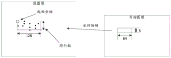
FIG. 4 is a schematic diagram of mapping a target image block to a source image block in an embodiment of the present invention;
FIG. 5 is a schematic diagram illustrating mapping of pixel points of a target image block to pixel points of a source image block in an embodiment of the present invention;
fig. 6 is a schematic diagram of a panoramic image stitching device in an embodiment of the present invention.
Detailed Description
In order to make the objects, technical solutions and advantages of the present invention more apparent, the technical solutions in the embodiments of the present invention will be clearly and completely described below with reference to the accompanying drawings in the embodiments of the present invention, and it is obvious that the described embodiments are only a part of the embodiments of the present invention, and not all of the embodiments.
All other embodiments, which can be derived by a person skilled in the art from the embodiments given herein without making any creative effort, shall fall within the protection scope of the present invention. The embodiments and features of the embodiments of the present invention may be arbitrarily combined with each other without conflict. Also, while a logical order is shown in the flow diagrams, in some cases, the steps shown or described may be performed in an order different than here.
First, please refer to fig. 1, which is a general concept of a panoramic image stitching method according to an embodiment of the present invention. For convenience of description, in fig. 1, a trinocular camera is taken as an example in the embodiment of the present invention, a panoramic image stitching method of an N-ocular camera is the same as that of the trinocular camera, and N is an integer greater than or equal to 1.
In fig. 1, a three-frame buffer space is opened up for each destination video stream, a source image is stored in a cyclic manner, and n is an integer greater than or equal to 1. Taking a standard video stream of a first target camera of the trinocular camera as an example, the obtained source image is stored in a Double Data Rate (DDR).
The method comprises the steps that when a first frame of source images are stored in a DDR (double data rate), target image block coordinates are generated according to the initial coordinates and the length and width dimensions of a preprocessed target image, pixel point coordinates of the source images corresponding to the coordinates of the target image blocks are calculated through operations such as back projection and distortion correction, initialization of the initial coordinates of the source image blocks corresponding to the target image blocks is completed after the pixel point coordinates of the source images are processed, and the operation is executed only once when power is on or parameters are changed. And reading a corresponding source image block from the DDR for each subsequent frame image from the second frame according to the source image initial coordinate, generating a target image block, and then generating a target image to be spliced.
After the three-eye camera respectively obtains the three target images, the three target images can be stored in the DDR according to a certain splicing sequence, the three target images are spliced into a panoramic image, the panoramic image can be read from the DDR by the follow-up three-eye camera, and a panoramic image quasi-video stream is output to rear-end display equipment.
In order to better understand the technical solution, the technical solution will be described in detail with reference to the drawings and the specific embodiments. It should be noted that the following embodiments are based on the same inventive concept, and when the contents of any one of the embodiments are understood or explained, the contents described in other embodiments may be referred to.
Example one
Referring to fig. 2, an embodiment of the present invention provides a panoramic image stitching method, which may be applied to a panoramic image stitching apparatus, such as a camera and a multi-view camera, where an implementation process of the method may be described as follows.
S101: acquiring a source image video stream, and determining a preset position information set, wherein one position information is used for indicating a specific coordinate position of a source image block in the source image video stream;
s102: respectively intercepting a corresponding source image block from a source image video stream based on each position information in the position information set;
s103: and generating a plurality of target images based on the obtained source image blocks, and splicing the target images to obtain corresponding panoramic images.
In S101, panoramic image stitching devices in different positions, such as a plurality of source images obtained by a plurality of cameras in different positions in real time, may be a source image video stream; or, a panoramic image stitching device, such as a multi-view camera, acquires a plurality of source images at different angles in real time, or may be a source image video stream, where the source images are usually spherical images.
The panoramic image splicing device can store the acquired source image video stream into a DDR (double data rate) for caching, wherein if the panoramic image splicing device is a multi-view camera, a three-frame cache space can be opened up for each view video stream, and the acquired source image can be stored in a circulating mode.
When the panoramic image stitching device acquires a source image video stream, a preset position information set can be determined, wherein the preset position information set comprises a plurality of position information, and one position information can be used for indicating a specific coordinate position of a source image block in the source image video stream.
In a possible implementation, the preset position information set is required before the source image video stream is acquired, which may be performed by, but is not limited to, the following manner.
Acquiring a sample source image set;
analyzing and processing each sample source image in the sample source image set, and converting into a corresponding target image;
acquiring splicing projection parameters of a target image corresponding to each sample source image, wherein the splicing projection parameters of one target image are used for at least indicating the initial coordinates and the length and width dimensions of the target image in the corresponding sample source image;
determining the position information of a plurality of target image blocks contained in the corresponding target image in the corresponding sample source image respectively based on the mosaic projection parameters of each target image;
and forming the obtained position information into a position information set.
In the embodiment of the invention, if the installation of the panoramic image splicing device is completed or the position of the panoramic image splicing device is changed, the panoramic image splicing device can acquire a sample source image set before the splicing of the panoramic image, wherein a plurality of source images included in the sample source image set can be acquired by the panoramic image splicing device at different positions, such as a plurality of cameras at different positions; alternatively, the plurality of source images included in the sample source image set may be acquired from different angles by a multi-view camera, and the like.
Then, the panoramic image stitching device may analyze and process each sample source image in the sample source image set, convert the sample source image into a corresponding target image, and may obtain a stitching projection parameter of the target image corresponding to each sample source image, where the stitching projection parameter of one target image is used to indicate at least a start coordinate and a length and width dimension of the target image in the corresponding sample source image.
In one possible implementation, the preprocessed stitched projection parameters may include one or more of geometric transformation parameters, distortion correction parameters, length and width parameters of the target image, and start coordinate parameters of the target image, where the geometric transformation parameters may be used to indicate that the source image of the spherical map is projected as a two-dimensional plane map.
Therefore, the panoramic image stitching device can independently and parallelly determine the position information of a plurality of target image blocks contained in the corresponding target images in the corresponding sample source images for each source image based on the stitching projection parameters of each target image.
In a possible implementation manner, based on the stitching projection parameters of any one target image, the position information of a plurality of target image blocks contained in the corresponding target image in the corresponding sample source image is determined, and the following can be implemented:
the panoramic image splicing device can divide any one target image according to length and width size parameters included in splicing projection parameters of any one target image to obtain a plurality of target image blocks; the size of the target image block can be determined by the range of the pixel points corresponding to the source image after the pixel points in the block are transformed by the back projection algorithm, the efficiency of the DDR and the logic resource condition of the hardware, and the length and width of the boundary block of the target image can be processed according to the actual condition, for example, the length and width or the area of the target image cannot be divided by the size or the area of the target image block to be divided, at this time, the length and width of the target image block at the boundary of the target image can be divided according to the actual condition.
Referring to fig. 3, a schematic diagram of the target image divided by blocks according to the embodiment of the present invention is shown, in fig. 3, the size of each target image block is 64 × 8.
The following operations are respectively executed for each target image block in a plurality of target image blocks contained in one target image block:
for a target image block, the starting position of the target image block may be determined according to the starting coordinate parameters included in the stitching projection parameters, and then the coordinates of each pixel point in the target image block may be calculated from left to right and from top to bottom, where the set of the coordinates of the pixel points is the first pixel point coordinate set of the target image block in the embodiment of the present invention.
Because the positions of the pixel points of the target image, which are mapped to the pixel points of the source image through the back projection algorithm, are uncertain, if the point-to-point mapping is used for directly reading data from the DDR, the utilization rate of the DDR is too low. According to the method and the device, the characteristic of image continuity is utilized, the pixel point of the target image block is mapped to the pixel point of the source image to be within a certain source image block range of the source image, and therefore point-to-point mapping is converted into the mapping of the target image block to the source image block. By adopting the characteristic of DDR burst transmission, the source image blocks mapped by the target image blocks are taken out of the DDR, the efficiency of the DDR is greatly improved, and the splicing of the panoramic image can be processed in real time.
Please refer to fig. 4, which is a diagram illustrating mapping of target image blocks to source image blocks according to an embodiment of the present invention.
Then, the panoramic image stitching device may calculate, according to the geometric transformation parameters included in the stitching projection parameters of one target image block, pixel coordinates of the obtained target image corresponding to pixel coordinates of the corresponding source image by using a back projection algorithm, that is, determine a second pixel coordinate set corresponding to the first pixel coordinate set in the sample source image corresponding to one target image.
Furthermore, the panoramic image stitching device can determine the position information of the target image block in the corresponding sample source image according to the second pixel point coordinate set corresponding to the target image block.
In a possible implementation manner, the panoramic image stitching device can correct the pixel point coordinates of the source image by adopting a distortion correction algorithm according to the distortion correction parameters.
In a possible implementation manner, the panoramic image stitching apparatus may determine, according to a second pixel coordinate set corresponding to one target image block, position information of the target image block in the corresponding sample source image, which may be performed by, but is not limited to, the following manner.
And calculating the abscissa and the ordinate of the pixel point coordinate in the second pixel point coordinate set corresponding to the target image block, and determining the minimum abscissa, the minimum ordinate and the maximum ordinate.
Determining a starting coordinate of a source image block corresponding to a target image block based on the minimum abscissa and the minimum ordinate, and determining a number of lines of traversal of the source image block corresponding to the target image block based on the minimum ordinate and the maximum ordinate.
For example, as shown in fig. 4, according to the characteristic of image continuity, the pixel points mapped to the source image in the target image block are necessarily within a certain region range, and all the pixel points mapped to the source image in the target image block are counted to obtain the minimum value of the abscissa (x axis) and the ordinate (y axis), that is, the initial coordinate of the source image block; meanwhile, the maximum value of the ordinate (y axis) is obtained, and the difference between the maximum value of the ordinate (y axis) and the minimum value of the ordinate (y axis), namely the number of the spanning rows of the source image blocks, is solved.
The panoramic image stitching device can determine the position information of the source image block corresponding to one target image block according to the starting coordinate and the number of the spanning lines.
Subsequently, the panoramic image stitching device may store the start coordinates and the number of lines in the source image block corresponding to all the target images in a Random Access Memory (RAM), that is, the initialization of the start coordinates of the source image block is completed.
The process of initializing the initial coordinates of the source image blocks is only completed within the time of one frame after the panoramic image splicing device is powered on or splicing projection parameters are changed, and the purpose is that after the splicing projection parameters are determined, the target image blocks can quickly position the corresponding source image blocks in the DDR. Meanwhile, the initialization process is calculated in real time, so that the panoramic image splicing device, such as a multi-view camera and the like, can adapt to different scene requirements, and meanwhile, the requirements on relative positions and included angles among the multi-view cameras are reduced. Only a group of source images are collected according to different application scenes of the multi-view camera to calculate splicing projection parameters, and the use flexibility of the multi-view camera is greatly improved.
S102 may then be entered, i.e. a corresponding source image block is truncated from the source image video stream based on each position information in the set of position information, respectively.
When each source image block is intercepted from a source image video stream, the panoramic image splicing device executes the following operations:
determining a third pixel point coordinate set of a source image block and a pixel value corresponding to each pixel point coordinate, wherein the third pixel point coordinate set comprises coordinates of all pixel points in the source image block;
and intercepting a corresponding source image block from the source image video stream based on the third pixel point coordinate set and the position information of one source image block.
That is to say, the panoramic image stitching device can determine the coordinates of all the pixel points in one source image block and the pixel value corresponding to each pixel point coordinate, and then can intercept the corresponding source image block from the source image video stream according to the pixel point coordinate sets and the position information of the source image block.
For example, the panorama image stitching device stores the previous frame of source image into the DDR within a frame time of initialization of the start coordinates of the source image blocks, and when the next frame of image starts, takes out the start address and the number of lines crossing of the first source image block from a storage unit, such as the RAM, and then calculates and determines the position and the size of the source image block in the DDR according to the start address and the number of lines crossing, thereby intercepting the corresponding first source image block from the source image video stream. The pixel values in the first source image block are then stored in a local memory location, such as a RAM.
And after the first source image block is read from the DDR, starting to read the initial address and the row spanning number of the next source image block, and reading the data of the next source image block and storing the data into the other RAM.
In S103, the panoramic image stitching device may generate a plurality of target images according to the obtained source image blocks, and stitch the plurality of target images to obtain corresponding panoramic images.
In one possible implementation, generating a plurality of target images based on the obtained source image blocks may be performed in the following manner.
Generating a target image block based on a source image block, performing the following operations:
reading pixel values of a plurality of pixel points corresponding to a second pixel point coordinate set of a target image block and pixel values of adjacent pixel points of each pixel point in the plurality of pixel points from a third pixel point coordinate set of a source image block.
For example, if the panorama image stitching device needs to read a pixel value of a pixel corresponding to a pixel coordinate of a target image block, the pixel value of the pixel corresponding to the pixel coordinate and a pixel value of an adjacent pixel may be searched from a source image block corresponding to the target image block according to the pixel coordinate of the target image block, where one pixel may have one or more adjacent pixels.
And weighting and averaging the read pixel value of one pixel point in the plurality of pixel points and the pixel value of an adjacent pixel point, and determining the pixel value of a pixel point corresponding to each pixel point coordinate in a second pixel point coordinate set. That is to say, if the pixel value of one pixel point and the pixel value of an adjacent pixel point are obtained, the pixel values of the two pixel points are weighted and averaged to obtain the pixel value of the pixel point corresponding to the corresponding pixel point coordinate in the target image block; or, if the pixel value of one pixel point and the pixel values of a plurality of adjacent pixel points are obtained, the pixel value of one pixel point and the pixel values of a plurality of adjacent pixel points are weighted and averaged, and the pixel value of the pixel point corresponding to the corresponding pixel point coordinate in the target image block can be obtained.
And generating a target image block based on the pixel value of the pixel point corresponding to each pixel point coordinate in the second pixel point coordinate set, namely generating the target image block with the pixel value to be spliced after determining the pixel value of the pixel point corresponding to each pixel point coordinate in the second pixel point coordinate set of the target image block.
For example, as shown in fig. 5, a schematic diagram of mapping pixel points of a target image block to pixel points of a source image block in an embodiment of the present invention is shown.
The panoramic image splicing device can take out the values of the pixel and the adjacent pixels from the RAM, obtain the value of the corresponding pixel point of the target image block by adopting a weighted averaging method, and quickly take out the pixel point of the source image block corresponding to the pixel point of the target image block from the RAM by utilizing the point-to-point mapping of the pixel point, so that the generation of the target image is completed, and the rate of searching the corresponding pixel point from the source image in a point-to-point mode is improved.
As shown in fig. 1, the generation of the target images of the trinocular camera is performed by parallel computation, and the target images obtained by the above method are stored in the DDR according to a preset rule to be spliced into a corresponding panoramic image, where the preset rule may be used to indicate the splicing sequence of the generated target images.
In practical application, the preset rule may be set according to the ranking of the cameras, for example, if the cameras are ranked from left to right, then we need to splice the panoramic image from left to right, and therefore the preset rule is to splice the target images from left to right.
If the adjacent target images are overlapped during splicing, the overlapped parts of the two adjacent target images can be fused by adopting methods such as weighting, averaging and the like, and then the fused target images are output to the rear-end display equipment according to the format of the standard video stream.
In summary, one or more technical solutions of the embodiments of the present invention have the following technical effects or advantages:
first, in the embodiments of the present invention, after a source image video stream is acquired and a preset position information set is determined, a specific coordinate position of a source image block in the source image video stream may be determined according to each position information in the preset position information set, and a corresponding source image block is captured from the source image video stream, and then a plurality of target images may be generated according to each obtained source image block, and the plurality of target images are stitched to obtain a corresponding panoramic image, thereby improving the stitching efficiency of the panoramic image.
Secondly, because the panoramic image splicing device in the embodiment of the invention has independent source image video streams such as a multi-view camera and the like, the panoramic image splicing device can process the source image video streams in parallel, thereby improving the processing efficiency of the panoramic image splicing and ensuring the real-time property of the panoramic image splicing. Meanwhile, each path of source image video stream is independently processed, so that the number of cameras can be conveniently expanded, and the video streams can be rapidly expanded into 4-mesh cameras, 5-mesh cameras, 6-mesh cameras and the like.
Thirdly, as the splicing projection parameter real-time configuration mode can be adopted in the embodiment of the invention, the parameters can be continuously debugged, and the seamless splicing effect can be achieved as long as the splicing projection parameters meet the requirements.
Fourthly, because the embodiment of the invention can adopt the modes of block division and three-layer addressing to complete the processing method of searching the corresponding pixel points by point-to-point mapping, the point-to-point searching efficiency is greatly improved, and the panoramic stitching is ensured to be completed in real time. The first layer addressing is to find the position of a source image in a DDR cache; the second layer of searching is to search the position of a source image block corresponding to the target image block in the source image; and the third layer of addressing is to find the position of the pixel point of the source image corresponding to the pixel point in the target image block in the RAM.
Fifth, the embodiment of the present invention provides a concept of initializing the starting coordinates of the source image block. The initialization process is completed within one frame time after the equipment is powered on or splicing projection parameters are changed, the position of a source image block corresponding to a target image block in the DDR can be predicted in advance, the source image block corresponding to the target image block is taken out from the DDR and stored in RAM resources of hardware before coordinates of the target image block are generated, and the processing efficiency is greatly improved. Meanwhile, the process can be carried out in real time, splicing projection parameters can be changed at any time, and equipment is not limited by the position and the included angle of the camera any more and the change of the external environment, so that the use flexibility of the equipment is improved.
Example two
Referring to fig. 6, based on the same inventive concept, an embodiment of the present invention provides a panoramic image stitching apparatus, which includes an acquisition module 61, a matching module 62, and a stitching module 63.
The acquisition module 61 is configured to acquire a source image video stream and determine a preset position information set, where one position information is used to indicate a specific coordinate position of a source image block in the source image video stream;
a matching module 62, configured to intercept a corresponding source image block from the source image video stream based on each position information in the position information set respectively;
and a stitching module 63, configured to generate a plurality of target images based on the obtained source image blocks, and stitch the plurality of target images to obtain corresponding panoramic images.
In a possible implementation manner, the apparatus further includes
A processing module, configured to preset the position information set before the source image video stream is acquired, and specifically includes:
acquiring a sample source image set;
analyzing and processing each sample source image in the sample source image set, and converting into a corresponding target image;
acquiring splicing projection parameters of target images corresponding to each sample source image, wherein the splicing projection parameters of one target image are used for at least indicating the initial coordinates and the length and width dimensions of the target image in the corresponding sample source image;
determining the position information of a plurality of target image blocks contained in the corresponding target image in the corresponding sample source image respectively based on the mosaic projection parameters of each target image;
and forming the obtained position information into a position information set.
In one possible implementation, the processing module is further configured to:
dividing any one target image based on length and width size parameters included in splicing projection parameters of any one target image to obtain a plurality of target image blocks;
respectively executing the following operations for each target image block:
aiming at a target image block, determining a first pixel point coordinate set of the target image block based on an initial coordinate parameter included by a splicing projection parameter, wherein the first pixel point coordinate set includes coordinates of all pixel points in the target image block;
determining a second pixel point coordinate set corresponding to the first pixel point coordinate set in the sample source image corresponding to the target image based on the splicing projection parameters of the target image block including geometric transformation parameters;
and determining the position information of the target image block in the corresponding sample source image based on the second pixel point coordinate set corresponding to the target image block.
In one possible implementation, the processing module is further configured to:
calculating the abscissa and the ordinate of the pixel point coordinate in the second pixel point coordinate set corresponding to the target image block, and determining the minimum abscissa, the minimum ordinate and the maximum ordinate;
determining the initial coordinate of the source image block corresponding to the target image block based on the minimum abscissa and the minimum ordinate, and determining the number of lines of the source image block corresponding to the target image block based on the minimum ordinate and the maximum ordinate;
and determining the position information of the source image block corresponding to the target image block based on the starting coordinate and the number of the spanning rows.
In a possible implementation manner, the matching module 62 is specifically configured to:
when each source image block is intercepted from the source image video stream, the following operations are executed:
determining a third pixel point coordinate set of one source image block and a pixel value corresponding to each pixel point coordinate, wherein the third pixel point coordinate set comprises coordinates of all pixel points in the one source image block;
and intercepting a corresponding source image block from the source image video stream based on the third pixel point coordinate set and the position information of the source image block.
In a possible implementation manner, the splicing module 63 is specifically configured to:
generating a target image block based on a source image block, performing the following operations:
reading pixel values of a plurality of pixel points corresponding to the second pixel point coordinate set of the target image block and pixel values of adjacent pixel points of each pixel point in the plurality of pixel points from a third pixel point coordinate set of the source image block;
weighting and averaging the read pixel value of one pixel point in the plurality of pixel points and the pixel value of an adjacent pixel point, and determining the pixel value of a pixel point corresponding to each pixel point coordinate in the second pixel point coordinate set;
and generating the target image block based on the pixel value of the pixel point corresponding to each pixel point coordinate in the second pixel point coordinate set.
In a possible implementation manner, the splicing module 63 is specifically configured to:
splicing a plurality of target images with pixel values based on a preset rule to obtain a panoramic image; the preset rule is used for indicating the splicing sequence of the generated target images.
EXAMPLE III
Based on the same inventive concept, the embodiment of the invention provides a panoramic image splicing device, which comprises:
at least one processor, and
a memory communicatively coupled to the at least one processor, a communication interface;
wherein the memory stores instructions executable by the at least one processor, and the at least one processor performs the method of embodiment one using the communication interface by executing the instructions stored by the memory.
Example four
Based on the same inventive concept, the embodiment of the present invention provides a computer-readable storage medium, which stores computer instructions that, when executed on a computer, cause the computer to perform the method of the first embodiment.
In particular implementations, the computer-readable storage medium includes: various storage media capable of storing program codes, such as a Universal Serial Bus flash drive (USB), a removable hard disk, a Read-Only Memory (ROM), a Random Access Memory (RAM), a magnetic disk, and an optical disk.
The above-described embodiments of the apparatus are merely illustrative, wherein units/modules illustrated as separate components may or may not be physically separate, and components shown as units/modules may or may not be physical units/modules, may be located in one place, or may be distributed over a plurality of network units/modules. Some or all of the modules may be selected according to actual needs to achieve the purpose of the solution of the present embodiment. One of ordinary skill in the art can understand and implement it without inventive effort.
Through the above description of the embodiments, those skilled in the art will clearly understand that each embodiment can be implemented by software plus a necessary general hardware platform, and certainly can also be implemented by hardware. With this understanding in mind, the above-described technical solutions may be embodied in the form of a software product, which can be stored in a computer-readable storage medium such as ROM/RAM, magnetic disk, optical disk, etc., and includes instructions for causing a computer device (which may be a personal computer, a server, or a network device, etc.) to execute the methods described in the embodiments or some parts of the embodiments.
Finally, it should be noted that: the above examples are only intended to illustrate the technical solution of the present invention, but not to limit it; although the present invention has been described in detail with reference to the foregoing embodiments, it will be understood by those of ordinary skill in the art that: the technical solutions described in the foregoing embodiments may still be modified, or some technical features may be equivalently replaced; and such modifications or substitutions do not depart from the spirit and scope of the corresponding technical solutions of the embodiments of the present invention.
Claims (9)
1. A panoramic image stitching method is characterized by comprising the following steps:
acquiring a sample source image set;
analyzing and processing each sample source image in the sample source image set, and converting into a corresponding target image;
acquiring splicing projection parameters of target images corresponding to each sample source image, wherein the splicing projection parameters of one target image are at least used for indicating the initial coordinates and the length and width dimensions of the target image in the corresponding sample source image;
determining the position information of a plurality of target image blocks contained in the corresponding target image in the corresponding sample source image respectively based on the mosaic projection parameters of each target image;
forming a position information set by the obtained position information;
acquiring a source image video stream, and determining the position information set, wherein one piece of position information is used for indicating a specific coordinate position of a source image block in the source image video stream;
intercepting a corresponding source image block from the source image video stream based on each position information in the position information set respectively;
and generating a plurality of target images based on the obtained source image blocks, and splicing the target images to obtain corresponding panoramic images.
2. The method of claim 1, wherein determining the position information of the target image blocks contained in the corresponding target images in the corresponding sample source images based on the stitched projection parameters of any one of the target images comprises:
dividing any one target image based on length and width size parameters included in splicing projection parameters of any one target image to obtain a plurality of target image blocks;
respectively executing the following operations for each target image block:
aiming at a target image block, determining a first pixel point coordinate set of the target image block based on an initial coordinate parameter included by a splicing projection parameter, wherein the first pixel point coordinate set includes coordinates of all pixel points in the target image block;
determining a second pixel point coordinate set corresponding to the first pixel point coordinate set in the sample source image corresponding to the target image block based on the splicing projection parameters of the target image block including geometric transformation parameters;
and determining the position information of the target image block in the corresponding sample source image based on the second pixel point coordinate set corresponding to the target image block.
3. The method of claim 2, wherein the determining the position information of the target image block in the corresponding sample source image based on the second set of pixel point coordinates corresponding to the one target image block comprises:
calculating the abscissa and the ordinate of the pixel point coordinate in the second pixel point coordinate set corresponding to the target image block, and determining the minimum abscissa, the minimum ordinate and the maximum ordinate;
determining the initial coordinate of the source image block corresponding to the target image block based on the minimum abscissa and the minimum ordinate, and determining the number of lines of the source image block corresponding to the target image block based on the minimum ordinate and the maximum ordinate;
and determining the position information of the source image block corresponding to the target image block based on the starting coordinate and the number of the spanning rows.
4. The method of claim 3, wherein said truncating a respective source image block from the source image video stream based on each position information in the set of position information, respectively, comprises:
when each source image block is intercepted from the source image video stream, the following operations are executed:
determining a third pixel point coordinate set of one source image block and a pixel value corresponding to each pixel point coordinate, wherein the third pixel point coordinate set comprises coordinates of all pixel points in the one source image block;
and intercepting a corresponding source image block from the source image video stream based on the third pixel point coordinate set and the position information of the source image block.
5. The method of claim 4, wherein generating a plurality of target images based on the obtained respective source image blocks comprises:
generating a target image block based on a source image block, performing the following operations:
reading pixel values of a plurality of pixel points corresponding to the second pixel point coordinate set of the target image block and pixel values of adjacent pixel points of each pixel point in the plurality of pixel points from a third pixel point coordinate set of the source image block;
weighting and averaging the read pixel value of one pixel point in the plurality of pixel points and the pixel value of an adjacent pixel point, and determining the pixel value of a pixel point corresponding to each pixel point coordinate in the second pixel point coordinate set;
and generating the target image block based on the pixel value of the pixel point corresponding to each pixel point coordinate in the second pixel point coordinate set.
6. The method of any one of claims 1-5, wherein said stitching the plurality of target images to obtain respective panoramic images comprises:
splicing a plurality of target images with pixel values based on a preset rule to obtain a panoramic image; the preset rule is used for indicating the splicing sequence of the generated target images.
7. A panoramic image stitching apparatus, characterized in that the apparatus comprises:
the acquisition module is used for acquiring a sample source image set, analyzing and processing each sample source image in the sample source image set, converting the sample source image into a corresponding target image, acquiring splicing projection parameters of the target image corresponding to each sample source image, determining position information of a plurality of target image blocks contained in the corresponding target image in the corresponding sample source image respectively based on the splicing projection parameters of each target image, and forming the acquired position information into a position information set; acquiring a source image video stream, and determining the position information set, wherein one piece of position information is used for indicating a specific coordinate position of a source image block in the source image video stream, and a splicing projection parameter of a target image is at least used for indicating a starting coordinate and a length and width dimension of the target image in a corresponding sample source image;
a matching module, configured to intercept a corresponding source image block from the source image video stream based on each position information in the position information set, respectively;
and the splicing module is used for generating a plurality of target images based on the obtained source image blocks, splicing the target images and obtaining corresponding panoramic images.
8. A panoramic image stitching apparatus, characterized in that the apparatus comprises:
at least one processor, and
a memory communicatively coupled to the at least one processor, a communication interface;
wherein the memory stores instructions executable by the at least one processor, the at least one processor performing the method of any one of claims 1-6 with the communications interface by executing the instructions stored by the memory.
9. A computer-readable storage medium characterized by:
the computer readable storage medium stores computer instructions that, when executed on a computer, cause the computer to perform the method of any of claims 1-6.
Priority Applications (4)
| Application Number | Priority Date | Filing Date | Title |
|---|---|---|---|
| CN201711148168.7A CN107945112B (en) | 2017-11-17 | 2017-11-17 | Panoramic image splicing method and device |
| PCT/CN2018/115405 WO2019096156A1 (en) | 2017-11-17 | 2018-11-14 | Methods and systems for image processing |
| EP18879498.6A EP3698316A4 (en) | 2017-11-17 | 2018-11-14 | Methods and systems for image processing |
| US16/876,104 US11455709B2 (en) | 2017-11-17 | 2020-05-17 | Methods and systems for image processing |
Applications Claiming Priority (1)
| Application Number | Priority Date | Filing Date | Title |
|---|---|---|---|
| CN201711148168.7A CN107945112B (en) | 2017-11-17 | 2017-11-17 | Panoramic image splicing method and device |
Publications (2)
| Publication Number | Publication Date |
|---|---|
| CN107945112A CN107945112A (en) | 2018-04-20 |
| CN107945112B true CN107945112B (en) | 2020-12-08 |
Family
ID=61931892
Family Applications (1)
| Application Number | Title | Priority Date | Filing Date |
|---|---|---|---|
| CN201711148168.7A Active CN107945112B (en) | 2017-11-17 | 2017-11-17 | Panoramic image splicing method and device |
Country Status (4)
| Country | Link |
|---|---|
| US (1) | US11455709B2 (en) |
| EP (1) | EP3698316A4 (en) |
| CN (1) | CN107945112B (en) |
| WO (1) | WO2019096156A1 (en) |
Families Citing this family (16)
| Publication number | Priority date | Publication date | Assignee | Title |
|---|---|---|---|---|
| CN107945112B (en) | 2017-11-17 | 2020-12-08 | 浙江大华技术股份有限公司 | Panoramic image splicing method and device |
| CN110503602B (en) * | 2018-05-18 | 2023-07-04 | 杭州海康微影传感科技有限公司 | Image projection transformation method and device and electronic equipment |
| CN109242772B (en) * | 2018-08-23 | 2023-01-31 | 上海圭目机器人有限公司 | Airport pavement surface image splicing method based on intelligent platform area-array camera acquisition |
| CN110246081B (en) * | 2018-11-07 | 2023-03-17 | 浙江大华技术股份有限公司 | Image splicing method and device and readable storage medium |
| CN109523468B (en) * | 2018-11-15 | 2023-10-20 | 深圳市道通智能航空技术股份有限公司 | Image stitching method, device, equipment and unmanned aerial vehicle |
| CN111105347B (en) * | 2019-11-19 | 2020-11-13 | 贝壳找房(北京)科技有限公司 | Method, device and storage medium for generating panoramic image with depth information |
| US11055835B2 (en) | 2019-11-19 | 2021-07-06 | Ke.com (Beijing) Technology, Co., Ltd. | Method and device for generating virtual reality data |
| CN111314729A (en) * | 2020-02-25 | 2020-06-19 | 广州华多网络科技有限公司 | Panoramic image generation method, device, equipment and storage medium |
| CN111729304B (en) * | 2020-05-26 | 2024-04-05 | 广州尊游软件科技有限公司 | Method for displaying mass objects |
| WO2021243566A1 (en) * | 2020-06-02 | 2021-12-09 | 深圳市大疆创新科技有限公司 | Imaging method, imaging apparatus, and computer readable storage medium |
| CN111738923A (en) * | 2020-06-19 | 2020-10-02 | 京东方科技集团股份有限公司 | Image processing method, apparatus and storage medium |
| US11652982B2 (en) * | 2020-10-30 | 2023-05-16 | Nvidia Corporation | Applications for detection capabilities of cameras |
| CN112907496A (en) * | 2021-02-24 | 2021-06-04 | 嘉楠明芯(北京)科技有限公司 | Image fusion method and device |
| EP4177823A1 (en) * | 2021-11-03 | 2023-05-10 | Axis AB | Producing an output image of a scene from a plurality of source images captured by different cameras |
| CN114289332A (en) * | 2022-01-20 | 2022-04-08 | 湖南视比特机器人有限公司 | Visual identification and positioning method and device for workpiece sorting and sorting system |
| CN115484417A (en) * | 2022-09-20 | 2022-12-16 | 深圳看到科技有限公司 | Video distribution method, device and equipment based on panoramic image and storage medium |
Family Cites Families (20)
| Publication number | Priority date | Publication date | Assignee | Title |
|---|---|---|---|---|
| CA2371349A1 (en) | 1998-05-13 | 1999-11-18 | Scott Gilbert | Panoramic movies which simulate movement through multidimensional space |
| US6775411B2 (en) * | 2002-10-18 | 2004-08-10 | Alan D. Sloan | Apparatus and method for image recognition |
| JP3977776B2 (en) * | 2003-03-13 | 2007-09-19 | 株式会社東芝 | Stereo calibration device and stereo image monitoring device using the same |
| US20080285652A1 (en) | 2007-05-14 | 2008-11-20 | Horizon Semiconductors Ltd. | Apparatus and methods for optimization of image and motion picture memory access |
| US8463074B2 (en) | 2009-11-11 | 2013-06-11 | General Dynamics Advanced Information Systems | System and method for rotating images |
| JP5434621B2 (en) * | 2010-01-19 | 2014-03-05 | ソニー株式会社 | Information processing apparatus, information processing method, and program thereof |
| JP5934929B2 (en) * | 2011-05-27 | 2016-06-15 | パナソニックIpマネジメント株式会社 | Image processing apparatus and image processing method |
| FR2989244B1 (en) | 2012-04-05 | 2014-04-25 | Current Productions | MULTI-SOURCE VIDEO INTERFACE AND NAVIGATION |
| US9264598B1 (en) | 2012-12-12 | 2016-02-16 | Amazon Technologies, Inc. | Collaborative image capturing |
| US10249029B2 (en) * | 2013-07-30 | 2019-04-02 | Apple Inc. | Reconstruction of missing regions of images |
| CN103763479B (en) | 2013-12-31 | 2017-03-29 | 深圳英飞拓科技股份有限公司 | The splicing apparatus and its method of real time high-speed high definition panorama video |
| CN105516597B (en) * | 2015-12-30 | 2018-11-13 | 完美幻境(北京)科技有限公司 | A kind of pan-shot processing method and processing device |
| CN106447608B (en) * | 2016-08-25 | 2017-11-07 | 中国科学院长春光学精密机械与物理研究所 | A kind of video image joining method and device |
| CN106815808A (en) * | 2017-01-20 | 2017-06-09 | 长沙全度影像科技有限公司 | A kind of image split-joint method of utilization piecemeal computing |
| CN106875339B (en) * | 2017-02-22 | 2020-03-27 | 长沙全度影像科技有限公司 | Fisheye image splicing method based on strip-shaped calibration plate |
| JP7203356B2 (en) * | 2017-03-31 | 2023-01-13 | パナソニックIpマネジメント株式会社 | Imaging system |
| CN107274346A (en) * | 2017-06-23 | 2017-10-20 | 中国科学技术大学 | Real-time panoramic video splicing system |
| WO2019084919A1 (en) * | 2017-11-03 | 2019-05-09 | SZ DJI Technology Co., Ltd. | Methods and system for infrared tracking |
| CN107945112B (en) * | 2017-11-17 | 2020-12-08 | 浙江大华技术股份有限公司 | Panoramic image splicing method and device |
| US20190180475A1 (en) * | 2017-12-08 | 2019-06-13 | Qualcomm Incorporated | Dynamic camera calibration |
-
2017
- 2017-11-17 CN CN201711148168.7A patent/CN107945112B/en active Active
-
2018
- 2018-11-14 EP EP18879498.6A patent/EP3698316A4/en active Pending
- 2018-11-14 WO PCT/CN2018/115405 patent/WO2019096156A1/en unknown
-
2020
- 2020-05-17 US US16/876,104 patent/US11455709B2/en active Active
Also Published As
| Publication number | Publication date |
|---|---|
| EP3698316A1 (en) | 2020-08-26 |
| WO2019096156A1 (en) | 2019-05-23 |
| US20200279357A1 (en) | 2020-09-03 |
| CN107945112A (en) | 2018-04-20 |
| US11455709B2 (en) | 2022-09-27 |
| EP3698316A4 (en) | 2021-03-03 |
Similar Documents
| Publication | Publication Date | Title |
|---|---|---|
| CN107945112B (en) | Panoramic image splicing method and device | |
| EP3664443B1 (en) | Panoramic image generation method and device | |
| CN111598993B (en) | Three-dimensional data reconstruction method and device based on multi-view imaging technology | |
| US10395341B2 (en) | Panoramic image generation method and apparatus for user terminal | |
| US10726580B2 (en) | Method and device for calibration | |
| WO2017088533A1 (en) | Method and apparatus for merging images | |
| WO2010028559A1 (en) | Image splicing method and device | |
| CA3029590A1 (en) | Method and device for performing mapping on spherical panoramic image | |
| CN110570367A (en) | Fisheye image correction method, electronic device and storage medium | |
| CN109005334A (en) | A kind of imaging method, device, terminal and storage medium | |
| CN110246081B (en) | Image splicing method and device and readable storage medium | |
| CN109035134B (en) | Panoramic image splicing method and device, electronic equipment and storage medium | |
| CN112215880B (en) | Image depth estimation method and device, electronic equipment and storage medium | |
| CN111292278B (en) | Image fusion method and device, storage medium and terminal | |
| US8019180B2 (en) | Constructing arbitrary-plane and multi-arbitrary-plane mosaic composite images from a multi-imager | |
| CN113643414A (en) | Three-dimensional image generation method and device, electronic equipment and storage medium | |
| US20220182595A1 (en) | Optical flow based omnidirectional stereo video processing method | |
| CN114648458A (en) | Fisheye image correction method and device, electronic equipment and storage medium | |
| GB2551426A (en) | Hardware optimisation for generating 360° images | |
| Rodrigues et al. | FPGA-based rectification of stereo images | |
| Lin et al. | Real-time low-cost omni-directional stereo vision via bi-polar spherical cameras | |
| CN115131507B (en) | Image processing method, image processing device and meta space three-dimensional reconstruction method | |
| CN113436247B (en) | Image processing method and device, electronic equipment and storage medium | |
| CN102750687A (en) | Method and device for camera parameter calibration and three-dimensional point cloud generating | |
| US9723216B2 (en) | Method and system for generating an image including optically zoomed and digitally zoomed regions |
Legal Events
| Date | Code | Title | Description |
|---|---|---|---|
| PB01 | Publication | ||
| PB01 | Publication | ||
| SE01 | Entry into force of request for substantive examination | ||
| SE01 | Entry into force of request for substantive examination | ||
| GR01 | Patent grant | ||
| GR01 | Patent grant |