CN107925828B - Advanced management of implantable sound management systems - Google Patents
Advanced management of implantable sound management systems Download PDFInfo
- Publication number
- CN107925828B CN107925828B CN201680029441.1A CN201680029441A CN107925828B CN 107925828 B CN107925828 B CN 107925828B CN 201680029441 A CN201680029441 A CN 201680029441A CN 107925828 B CN107925828 B CN 107925828B
- Authority
- CN
- China
- Prior art keywords
- sound
- microphone
- hearing prosthesis
- management system
- recipient
- Prior art date
- Legal status (The legal status is an assumption and is not a legal conclusion. Google has not performed a legal analysis and makes no representation as to the accuracy of the status listed.)
- Active
Links
Images


Classifications
-
- H—ELECTRICITY
- H04—ELECTRIC COMMUNICATION TECHNIQUE
- H04R—LOUDSPEAKERS, MICROPHONES, GRAMOPHONE PICK-UPS OR LIKE ACOUSTIC ELECTROMECHANICAL TRANSDUCERS; DEAF-AID SETS; PUBLIC ADDRESS SYSTEMS
- H04R25/00—Deaf-aid sets, i.e. electro-acoustic or electro-mechanical hearing aids; Electric tinnitus maskers providing an auditory perception
- H04R25/50—Customised settings for obtaining desired overall acoustical characteristics
- H04R25/505—Customised settings for obtaining desired overall acoustical characteristics using digital signal processing
-
- H—ELECTRICITY
- H04—ELECTRIC COMMUNICATION TECHNIQUE
- H04R—LOUDSPEAKERS, MICROPHONES, GRAMOPHONE PICK-UPS OR LIKE ACOUSTIC ELECTROMECHANICAL TRANSDUCERS; DEAF-AID SETS; PUBLIC ADDRESS SYSTEMS
- H04R25/00—Deaf-aid sets, i.e. electro-acoustic or electro-mechanical hearing aids; Electric tinnitus maskers providing an auditory perception
- H04R25/30—Monitoring or testing of hearing aids, e.g. functioning, settings, battery power
- H04R25/305—Self-monitoring or self-testing
-
- H—ELECTRICITY
- H04—ELECTRIC COMMUNICATION TECHNIQUE
- H04R—LOUDSPEAKERS, MICROPHONES, GRAMOPHONE PICK-UPS OR LIKE ACOUSTIC ELECTROMECHANICAL TRANSDUCERS; DEAF-AID SETS; PUBLIC ADDRESS SYSTEMS
- H04R3/00—Circuits for transducers, loudspeakers or microphones
- H04R3/005—Circuits for transducers, loudspeakers or microphones for combining the signals of two or more microphones
-
- H—ELECTRICITY
- H04—ELECTRIC COMMUNICATION TECHNIQUE
- H04R—LOUDSPEAKERS, MICROPHONES, GRAMOPHONE PICK-UPS OR LIKE ACOUSTIC ELECTROMECHANICAL TRANSDUCERS; DEAF-AID SETS; PUBLIC ADDRESS SYSTEMS
- H04R2225/00—Details of deaf aids covered by H04R25/00, not provided for in any of its subgroups
- H04R2225/67—Implantable hearing aids or parts thereof not covered by H04R25/606
-
- H—ELECTRICITY
- H04—ELECTRIC COMMUNICATION TECHNIQUE
- H04R—LOUDSPEAKERS, MICROPHONES, GRAMOPHONE PICK-UPS OR LIKE ACOUSTIC ELECTROMECHANICAL TRANSDUCERS; DEAF-AID SETS; PUBLIC ADDRESS SYSTEMS
- H04R2460/00—Details of hearing devices, i.e. of ear- or headphones covered by H04R1/10 or H04R5/033 but not provided for in any of their subgroups, or of hearing aids covered by H04R25/00 but not provided for in any of its subgroups
- H04R2460/01—Hearing devices using active noise cancellation
Abstract
A hearing prosthesis comprising an implantable microphone and a sound management system, wherein the hearing prosthesis is configured to set an operating parameter of the sound management system based on input from a microphone external to a recipient of the implantable microphone.
Description
Cross Reference to Related Applications
This application claims 2015 filed on 21/5.21 under the name batiaan VAN DIJK, entitled "advanced management OF IMPLANTABLE SOUND management system (ADVANCED MANAGGEMENT OF AN imprantable SOUND SOUND MANAGEMENT SYSTEM)" as priority OF the inventor, provisional U.S. patent application No.62/164,669, the entire contents OF which are incorporated herein by reference in its entirety.
Background
Hearing loss, which may be caused by many different reasons, is generally of two types: conductive and sensorineural. Sensorineural hearing loss is caused by a lack or damage of hair cells in the cochlea that convert sound signals into nerve impulses. Various hearing prostheses are commercially available to provide an individual suffering from sensorineural hearing loss with the ability to perceive sound. One example of a hearing prosthesis is a cochlear implant.
Conductive hearing loss occurs when the normal mechanical pathways that provide sound to the hair cells in the cochlea are obstructed (e.g., due to damage to the ossicular chain or ear canal). Individuals suffering from conductive hearing loss may retain some form of residual hearing because the hair cells in the cochlea may remain undamaged.
Hearing aids rely on the principle of air conduction to send acoustic signals to the cochlea. In particular, hearing aids typically use an arrangement positioned in or on the ear canal of the recipient to amplify sound received by the outer ear of the recipient. This amplified sound reaches the cochlea, causing the movement of perilymph and the stimulation of the auditory nerve.
In contrast to hearing aids, which rely primarily on the principle of air conduction, certain types of hearing prostheses, often referred to as cochlear implants, convert received sound into electrical stimulation. Electrical stimulation is applied to the auditory nerve in the cochlea, which results in the received sound being perceived.
Another type of hearing prosthesis uses an actuator to mechanically vibrate the ossicular chain, whereby an amplified signal may reach the cochlea. Depending on the level of hearing loss, this type of hearing prosthesis may have utility for both conductive and sensorineural loss.
Disclosure of Invention
According to an exemplary embodiment, there is a hearing prosthesis comprising an implantable microphone and a noise cancellation system, wherein the hearing prosthesis is configured to set at least one operating parameter of the noise cancellation system based on input from a microphone external to a recipient of the implantable microphone.
According to another exemplary embodiment, there is a method comprising: first data is developed based on ambient sound captured external to the recipient, and a noise cancellation system of the implantable sound capture system is controlled based at least in part on the first data.
According to another exemplary embodiment, there is a system comprising a noise cancellation subsystem configured to at least partially cancel a body conducted noise component from a first signal, wherein the first signal comprises the body conducted noise component and an ambient sound component, and the system is further configured to at least partially cancel the body conducted noise component using a first algorithm, the first algorithm being based on a second signal that temporally precedes the first signal, wherein the second signal is based on a capture sound, the capture sound being at least one of: (i) no body-conducted noise at all, or (ii) consisting entirely of ambient sound.
Drawings
Embodiments of the invention are described below with reference to the accompanying drawings, in which:
fig. 1 is a perspective view of an exemplary hearing prosthesis to which at least some of the teachings detailed herein are applicable;
fig. 2 schematically illustrates an implantable hearing system incorporating an implantable microphone assembly and a motion sensor 70;
FIG. 3A functionally illustrates an exemplary use of an adaptive filter;
fig. 3B functionally depicts an exemplary embodiment of a system usable in the hearing prosthesis of fig. 1, functionally operating in accordance with the example of fig. 3A;
FIG. 3C depicts an exemplary flow diagram according to an exemplary process;
FIG. 4 is a schematic diagram of an embodiment of an implantable hearing prosthesis utilizing a plurality of cancellation filters;
FIG. 5 depicts an exemplary flow diagram according to another exemplary process;
FIG. 6 depicts a plot of operating parameters in a unit circle;
FIG. 7 illustrates the fitting of a straight line to a first set of operating parameters that define a range of latent variables;
FIG. 8 illustrates a linear regression analysis of system parameters for latent variables;
FIG. 9 depicts a plot of microphone ADC output and accelerometer ADC output versus time for the case where the own voice body conducted noise phenomenon causes the noise cancellation algorithm to seek the wrong set of parameters;
FIG. 10 depicts a graph of phi versus time for the normal evolution of the pose variables phi1 and phi2 in the case where the effects of own voice body noise do not affect the noise cancellation algorithm;
FIG. 11A depicts a graph of phi versus time for the normal evolution of the pose variables phi1 and phi2 in the case where the effects of own voice body noise affect the noise cancellation algorithm;
FIG. 11B depicts an exemplary flow chart according to an exemplary process in accordance with an exemplary embodiment;
FIG. 11C depicts an exemplary flow chart in accordance with an exemplary process in accordance with an exemplary embodiment;
FIG. 11D depicts an exemplary flow chart in accordance with an exemplary process in accordance with an exemplary embodiment;
11E and 11F are exemplary collected data for an exemplary scenario in accordance with an exemplary embodiment;
FIG. 11G is an exemplary gain regime developed based on the data of FIGS. 11E and 11F in an exemplary scenario;
fig. 12 functionally depicts another exemplary embodiment of a system usable in the hearing prosthesis of fig. 1; and
fig. 13 functionally depicts another exemplary embodiment of a system usable in the hearing prosthesis of fig. 1.
Detailed Description
Fig. 1 is a perspective view of a fully implantable cochlear implant (referred to as cochlear implant 100) implanted in a recipient for which some embodiments and/or variations thereof detailed herein are applicable. The fully implantable cochlear implant 100 is part of the system 10, and in some embodiments, the system 10 may include external components, as will be described below. Note that in at least some embodiments, the teachings detailed herein are applicable to any type of hearing prosthesis having an implantable microphone.
Note that in alternative embodiments, the teachings detailed herein and/or variations thereof may be applicable to other types of hearing prostheses, such as, for example, bone conduction devices (e.g., active percutaneous bone conduction devices), Direct Acoustic Cochlear Implants (DACI), and so forth. Embodiments may include any type of hearing prosthesis that may utilize the teachings detailed herein and/or variations thereof. It is further noted that in some embodiments, the teachings detailed herein and/or variations thereof may be used in other types of prostheses besides hearing prostheses.
The recipient has an outer ear 101, a middle ear 105, and an inner ear 107. The following describes the components of outer ear 101, middle ear 105, and inner ear 107, followed by cochlear implant 100.
In a fully functional ear, outer ear 101 includes a pinna 110 and an ear canal 102. The sound pressure or sound wave 103 is collected by the pinna 110 and is transmitted through the passage into the ear canal 102 and through the ear canal 102. Disposed across the distal end of the ear canal is a tympanic membrane 104 that vibrates in response to sound waves 103. The vibrations are coupled to the oval or oval window 112 through the three bones of the middle ear 105, collectively referred to as the ossicles 106, and including the malleus 108, the incus 109, and the stapes 111. Bones 108, 109 and 111 of middle ear 105 are used to filter and amplify sound wave 103, causing oval window 112 to emit sound, or vibrate in response to vibration of tympanic membrane 104. The vibrations create waves of fluid motion of the perilymph within the cochlea 140. Such fluid movement in turn activates tiny hair cells (not shown) inside the cochlea 140. Activation of the hair cells causes appropriate nerve impulses to be generated and transmitted through the spiral ganglion cells (not shown) and the auditory nerve 114 to the brain (also not shown) where they are perceived as sound.
As shown, cochlear implant 100 includes one or more components that are temporarily or permanently implanted in the recipient. Cochlear implant 100 is shown in fig. 1 with external device 142, external device 142 being part of system 10 (along with cochlear implant 100), external device 142 being configured to provide power to the cochlear implant, as described below, wherein the implanted cochlear implant includes a battery that is recharged with power provided from external device 142. In the illustrative arrangement of fig. 1, the external device 142 may include a power supply (not shown) disposed in the ear-to-ear (BTE) unit 126. The external device 142 also includes components of the transcutaneous energy transfer link, referred to as external energy transfer assemblies. The transcutaneous energy transfer link is used to transfer power and/or data to cochlear implant 100. Various types of energy transfer, such as Infrared (IR), electromagnetic, capacitive, and inductive transfer, may be used to transfer power and/or data from external device 142 to cochlear implant 100. In the illustrative embodiment of fig. 1, the external energy transfer assembly includes an external coil 130 that forms part of an inductive Radio Frequency (RF) communication link. The external coil 130 is typically a wire antenna coil composed of multiple turns of electrically insulated single or multiple strands of platinum or gold wire. The external device 142 also includes magnets (not shown) positioned within the multiple turns of the external coil 130. Optionally, the external device 142 includes a microphone 127 (sometimes referred to herein as an external microphone) that may be used as a supplement/replacement to the implantable microphone assembly as described in detail below, but in other embodiments the cochlear implant includes a separate external microphone from the BTE device (the BTE device may also optionally include the microphone 127). Thus, the external device shown in fig. 1 is merely illustrative, and other external devices may be used with embodiments of the present invention.
The primary implantable component 120 further includes a stimulator unit (also not shown) that generates electrical stimulation signals based on the data signals. Electrical stimulation signals are delivered to the recipient via elongate electrode assembly 118.
The elongate electrode assembly 118 has a proximal end connected to the primary implantable component 120 and a distal end implanted in the cochlea 140. Electrode assembly 118 extends from main implantable assembly 120, through mastoid bone 119, to cochlea 140. In some embodiments, the electrode assembly 118 may be implanted at least in the base region 116, and sometimes further. For example, electrode assembly 118 may extend toward the apical end of cochlea 140 (referred to as cochlea apex 134). In some cases, electrode assembly 118 may be inserted into cochlea 140 via cochleostomy 122. In other cases, the floor of the cochlea may be formed through the circular window 121, the oval window 122, the promontory 123, or through the roof turn 147 of the cochlea 140.
As noted, cochlear implant 110 comprises a fully implantable prosthesis that is capable of operating without the need for external device 142, at least for a period of time. Accordingly, cochlear implant 100 further includes a rechargeable power source (not shown) that stores power received from external device 142. The power source may include, for example, a rechargeable battery. During operation of cochlear implant 100, the power stored by the power source is distributed to various other implanted components as needed. The power source may be located in the primary implantable component 120 or at a separate implanted location.
Note that the teachings detailed herein and/or variations thereof may be utilized with prostheses that are not fully implantable. That is, in an alternative embodiment of cochlear implant 100, cochlear implant 100 is a conventional hearing prosthesis.
In some exemplary embodiments, the signal sent to the stimulator of the cochlear implant may be derived from an external microphone, in which case the system is referred to as a semi-implantable device, or from an implanted microphone, which is then referred to as a fully implantable device. DACI may also use implanted microphones and thus also fully implantable devices. Fully implantable devices may have utility by exhibiting improved aesthetics, improved immunity to certain noises (e.g., wind noise), exhibiting little chance of loss or damage, and may at least sometimes be more resistant to clogging by debris, water, or the like. DACI can have practical value by keeping the ear canal open, which can reduce the likelihood of ear canal infection that would otherwise be wet, often affected by cerumen (ear wax), and painful due to the need for a tight fit for non-implanted hearing aids.
The implanted microphone may detect pressure. In at least some embodiments, they are configured to detect air pressure that is subsequently transmitted through the tissue to the microphone. Implanted microphones may detect other pressures presented to their surface, which may be undesirable in some situations. One type of pressure that may represent an impairment to the performance of an implanted microphone is the pressure due to acceleration. In some embodiments, if the hearing prosthesis is within the desired operating frequency range of the prosthesis (typically 20Hz to 20kHz, 20Hz to 10kHz, or 20Hz to 8kHz), such acceleration may have a detrimental effect on the hearing prosthesis, although the narrower range still gives satisfactory speech intelligibility. Acceleration may be caused by, for example, footstep impacts during walking, movement of soft tissue relative to harder tissue, abrasion of harder tissue relative to each other, chewing, and articulation. In the case of DACI, acceleration may be caused by the actuator driving the ossicle.
In some embodiments, acceleration causes pressure on the microphone, which cannot distinguish between a desired pressure due to external sounds and a very undesired pressure due to internal vibrations originating directly from the body or transmitted through the body to the microphone from an implanted actuator. Acceleration can be thought of as causing these pressures by means of a microphone driven into the tissue. If the microphone is mounted firmly on the skull and the skull vibrates perpendicular to its surface, the microphone membrane will be driven into the tissue, which may present a reaction force to the microphone due to its mass, and hence inertia. The reaction force divided by the area of the microphone is the pressure generated by the acceleration. The formula for the acceleration pressure may be:
ΔP=ρ·t·a
wherein Δ P is higher than P0Instantaneous pressure (ambient pressure), ρ is the average density of tissue over the microphone, t is the average thickness of tissue over the microphone, and a is the instantaneous acceleration. When the acceleration is vertical, but into the surface, rather than away from the surface, a pressure drop occurs, rather than an increase.
In some cases, there may be a practical value in reducing signal output due to acceleration. Because the relative pressure of body propagation versus air propagation of an implanted microphone is typically 10-20dB higher than that which occurs in normal hearing, body-emitted sounds may be a bit louder relative to externally-emitted sounds. Such a large vibration to acoustic signal ratio is experienced by recipients as clattering and rumbling during movement, very noisy chewing, and their own voice being unusually loud relative to other speakers. At the same time, it should be noted that there is utility value in avoiding the recipient's own voice being eliminated, in whole or in part. Complete cancellation of the recipient's own voice may, in some embodiments, result in the recipient speaking very loudly compared to other speakers. It is therefore practical to reduce the ratio of vibration to acoustic signal to a level, such as the level visible in normal hearing. In some embodiments, this may be achieved by effectively reducing the acceleration pressure/air-borne pressure sensitivity by 10-20 dB. By doing so, a similar ratio of acoustic signal to vibration signal as experienced in normal hearing can be achieved, and therefore a more natural listening experience.
In addition, the signals propagated by the body from the actuators as in DACI can be amplified by signal processing of the implant and can exhibit a gain greater than 1 at a frequency around the loop formed by the microphone, signal processing, actuators and tissue. This may be the case when high gains are handled, such as may be the case with medium to large hearing losses. In such cases, unless additional steps such as those disclosed herein are taken, the hearing prosthesis system may be positively fed back at a certain frequency and begin to "ring" or oscillate. The oscillations can reduce speech intelligibility, effectively masking at least the frequencies at which the oscillations are occurring, and generally other frequencies, by a psychoacoustic phenomenon known as mask propagation. This is annoying to the recipient, because oscillations may occur at very loud levels and cause an increased load on the battery, thereby reducing the time required between replacing or charging the battery. This may require a much larger feedback reduction of 25-55dB (typically 35-45dB) and may depend on the recipient's hearing loss, since the greater the recipient's hearing loss, the greater the gain that needs to be imparted in the signal processing, at least in some cases. It can thus be seen that a fully implantable DACI may require greater attenuation to reduce (including remove) feedback to balance air and bone conducted sound level differences, such as may be required in a fully implantable cochlear implant.
Exemplary embodiments that include an implantable microphone assembly utilize a motion sensor to reduce the effects of noise (including mechanical feedback and biological noise) in the output response of the implantable microphone assembly. In an exemplary embodiment, the diaphragm of the implantable microphone assembly that vibrates due to waves originating from ambient sounds traveling through the recipient's skin may also be affected by body noise or the like. To actively address non-ambient noise sources of vibration of the diaphragm of the implantable microphone (e.g., body noise conducted through the recipient's tissue to the microphone, which in at least some embodiments is not an audible energy level and/or frequency at a location remote from the recipient, but is an energy level and/or frequency that is not audible at least in the absence of a sound enhancement device), and thus the resulting unwanted movement between the diaphragm and the overlying tissue, some embodiments utilize a motion sensor to provide an output response that is proportional to the vibrational movement experienced by the microphone assembly. In general, the motion sensor may be mounted anywhere such that it is capable of providing a sufficiently accurate representation of vibrations received by the implantable microphone in general, and the membrane of the implantable microphone in particular. The motion sensor may be part of an assembly containing the microphone/its diaphragm, while in an alternative embodiment it may be housed in a separate assembly (e.g., a separate housing, etc.). In an exemplary embodiment, the motion sensor is substantially isolated from the reception of ambient acoustic signals originating from ambient sound that transcutaneously pass through tissue on the microphone/microphone diaphragm and are received by the microphone diaphragm. In this regard, the motion sensor may provide an output response/signal indicative of motion (e.g., caused by vibration and/or acceleration), while the transducer of the microphone may generate an output response/signal indicative of both transcutaneously received acoustic sound and motion. Thus, the output response of the motion sensor may be removed from the output response of the microphone to reduce the effect of motion on the implanted hearing system.
Therefore, in order to remove noise (including feedback and biological noise), it is practical to measure the acceleration of the microphone assembly. Fig. 2 schematically illustrates an implantable hearing system incorporating an implantable microphone assembly having a microphone 12 including a diaphragm and a motion sensor 70. As shown, motion sensor 70 further includes a filter 74, which filter 74 is used to match the output response Ha of motion sensor 70 to the output response Hm of microphone 12. Notably, the diaphragm of the microphone 12 accepts desired acoustic signals (e.g., from ambient sources 103), as well as undesired signals from biological sources (e.g., vibrations caused by speaking, chewing, etc.), and feedback received by the tissue feedback loop 78 from the output device 108 depending on the type of output device 108 (e.g., bone conduction vibration device, DACI actuator, and, in some cases, cochlear implant electrode array). In contrast, the motion sensor 70 is substantially isolated (including completely isolated) from surrounding sources and accepts only undesired signals caused by biological sources and/or caused by feedback received via the feedback loop 78. Thus, the output of the motion sensor 70 corresponds to an undesired signal component of the microphone 12. However, the amplitude of the output channels (i.e., the output response Hm of the microphone 12 and the output response Ha of the motion sensor 70) may be different and/or shifted in phase and/or have an offset frequency response. To remove undesired signal components from the microphone output response Hm, the filter 74 and/or system processor may operate to filter one or both of the responses to provide scaling, phase shifting, and/or frequency shaping. The output responses Hm and Ha of the microphone 12 and the motion sensor 70 are then combined by a summing unit 76, the summing unit 76 producing a net output response Hn having a reduced response to the undesired signal, at least if the filter 74 has the correct response.
To implement filter 74 for scaling and/or phase shifting the output response Ha of motion sensor 70 to remove the effects of feedback and/or biological noise from microphone output response Hm, a system model of the relationship between the output responses of microphone 12 and motion sensor 17 is identified/developed. That is, filter 74 may operate to manipulate the output response Ha of motion sensor 70 to the biological noise and/or feedback to replicate the output response of microphone 12 to the same biological noise and/or feedback. In this regard, the filtered output responses Haf and Hm may be substantially the same amplitude and phase prior to combining (e.g., subtracting/cancelling). It will be noted, however, that such a filter 74 need not manipulate the output response Ha of the motion sensor 70 to match the microphone output response Hm for all operating conditions. Instead, the filter 74 may match the output responses Ha and Hm at a predetermined set of operating conditions, including, for example, a desired frequency range (e.g., acoustic hearing range) and/or one or more passbands. It is also noted that filter 74 can adapt the ratio of microphone output response Hm to motion sensor output response Ha to acceleration, so any change in the feedback path that leaves the ratio of response to acceleration constant has little or no effect on good cancellation. Such an arrangement thus has a significantly reduced sensitivity to the posture of the recipient, to the clenching of the teeth, etc.
The exemplary embodiments utilize tunable filters, such as, by way of example only and not limitation, adaptive filter(s) that filter out body noise, and the like. More specifically, fig. 3A functionally illustrates an exemplary utility of such an adaptive filter. Any filter arrangement that can enable the teachings detailed herein and/or variations thereof to be implemented can be used in at least some embodiments in fig. 3A, the bio-noise is modeled with accelerations at the microphone assembly that are filtered by a linear process K. The signal is added to the acoustic signal at the surface of the microphone element. In this regard, the microphone 12 sums the signals. If the combination of K and acceleration is known, the combination of the accelerometer output and the adaptive/tunable filter can be tuned to K. This is then subtracted from the microphone output. This will result in a clean or clean audio signal with reduced bio-noise components. This net signal may then be passed to a signal processor where it may be processed by the hearing system.
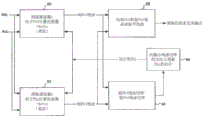
Fig. 3B functionally depicts an exemplary embodiment of a system 400 usable in the hearing prosthesis 10 of fig. 1, the system 400 functionally operating according to the schematic of fig. 3A, along with additional functionality as will be detailed below. As can be seen, system 400 includes a microphone 412 and an accelerometer 470. The microphone 412 is configured such that it receives signals derived from ambient sounds as well as biological/body noise, which in at least some embodiments includes signals derived from the recipient's own voice traveling through the body via bone/tissue conduction. These latter signals are added to the signals derived from the ambient sound at the microphone 412, since the microphone 412 detects both signals. In contrast, the accelerometer 470 is ideally functionally isolated from signals derived from ambient sound and generally only responds to body noise signals and/or feedback signals. The system 400 incorporates an adaptive filter device 450 controlled by a control unit 440, the control unit 440 running an adaptive algorithm to control the filter(s) of the tunable filter device 450. Details of the adaptive algorithm are provided below, but in brief, it can be seen that the output of the adaptive filter device 450 controlled by the filter control unit 440 is fed to an adder 430 where it is added to (or more precisely subtracted from) the output of the microphone 412 and, optionally, delivered to a signal processor and/or output means (not shown, but for example a receiver stimulator for a cochlear implant, an actuator for a DACI and/or an actuator (vibrator) for an active transcutaneous bone conduction means) in accordance with the positioning of a switch 434 which functionally represents controlling the system in an implanted microphone mode or an external microphone mode, described in more detail below). The accelerometer 470, the tunable filter 450, the filter control unit 440, and the adder 430 collectively correspond to an adaptive noise cancellation subsystem 460. Control unit 440 runs an adaptive algorithm to control the filter(s) of adjustable filter device 450, e.g., based at least in part on feedback of the signal output by summer 430.
The adaptive filter may perform this process using ambient signals and acoustic signals of acceleration plus filtered acceleration. The adaptive algorithm and the tunable filter may take many forms, such as continuous, discrete, Finite Impulse Response (FIR), Infinite Impulse Response (IIR), trellis, systolic array, and the like. Some exemplary algorithms of the adaptive algorithm include random gradient-based algorithms such as the Least Mean Square (LMS) algorithm and recursive algorithms such as RLS. Alternatively and/or in addition, numerically more stable algorithms may be used in some alternative embodiments, such as QR decomposition with RLS (QRD-RLS) and fast implementation somewhat similar to FFT. The adaptive filter may incorporate an observer, which is a module that determines one or more expected states of the microphone/motion sensor system. The observer may use one or more observed states/variables to determine appropriate or practical filter coefficients. Converting the observer's observations into filter coefficients may be performed by a function, a look-up table, or the like. In some exemplary embodiments, the adaptive algorithm may be written to operate primarily in the digital signal processor "background", thereby freeing up resources needed for real-time signal processing.
Still referring to fig. 3B, it can be seen that system 400 includes a microphone 427, in at least some example embodiments, microphone 427 corresponds to external microphone 127 of fig. 1, detailed above. That is, in an exemplary embodiment, the microphone 427 may be part of the BTE device 126, and the sound captured by the microphone 427 may be converted by the microphone to a signal representative of the captured sound and then transcutaneously transmitted to an implantable portion of the hearing prosthesis (represented in fig. 3B by the wireless link symbol 429) where the signal is processed by the implantable components for later use in invoking hearing perception in accordance with the teachings detailed herein. That is, in an alternative embodiment, the microphone 427 may correspond to a remote microphone that is separate from the BTE device 126. By way of example only, and not limitation, the microphone 427 may be a microphone that is placed on a table or the like and that wirelessly (or in a wired manner) transmits a signal to the BTE device (or another device in communication with the implantable component) such that the signal is transcutaneously transmitted to the implantable component. Still further, in an exemplary embodiment, two or more wireless links may exist between the microphone 427 and the output of the system 400, allowing for multiple microphones. Any apparatus, system, and/or method that implements an external microphone as system 400 that would enable the teachings detailed herein and/or variations thereof to be implemented may be used in at least some embodiments.
As seen in fig. 3B, switch 434 controls output from microphone 427 to a signal processor and/or output device (not shown, but such as a receiver stimulator of a cochlear implant, an actuator of a DACI, and/or an actuator (vibrator) of an active transcutaneous bone conduction device) of hearing prosthesis system 400. That is, in an exemplary embodiment, the hearing perceptions invoked by the system 400 may be variously based on the implantable microphone 412 or the external microphone 427, respectively. In this regard, in at least some embodiments, hearing perception based on sounds effectively isolated (including isolated) from body conducted noise through the use of an external microphone 427 as opposed to an implantable microphone 412 can be invoked. Thus, in an exemplary embodiment, the switch 434 enables the system 400 to provide the recipient with the ability to switch between the convenience of utilizing the implantable microphone 412 without an external microphone, thereby enabling the system 400 to function as a fully implantable hearing prosthesis, and obtaining hearing perceptions based on captured sounds that are less affected and/or effectively isolated naturally from body conducted noise (as opposed to sounds captured by the implantable microphone 412). In this regard, in at least some embodiments, switch 434 passes the output from adaptive noise cancellation subsystem 460 by (i) blocking the output of adaptive noise cancellation subsystem 460 and (more precisely, passing a signal based on the output of external microphone 427) and (ii) blocking the output of external microphone 427 (if present), respectively.
Still referring to fig. 3B, it can be seen that system 400 includes two different feedback paths from summer 430 to filter control unit 440. The first path, path 1, is the path that inputs the unmodified signal from adder 430 back to control unit 440. In this regard, in an exemplary embodiment, filter control unit 440 controls the filter based only on the output from adder 430 or only on the output from adder 430 and other inputs to filter control unit 440 (useful for enabling adaptive noise cancellation subsystem 460 to operate). Control unit 440 runs an adaptive algorithm to control the filter(s) of tunable filter device 450, e.g., based at least in part on feedback of the signal output by summer 430.
The second path (path 2) is a path that also extends from the adder 430 to the control unit 440, but also includes the adder 432. Via path 2, the output from the adaptive noise cancellation subsystem in adder 430 is added to (or more precisely subtracted from) the output of external microphone 427 and passed to control unit 440. Briefly note that in the absence of a signal from an external microphone, or in the presence of a blockage of the signal from the microphone (which may correspond to an embodiment where, for example, a switch is positioned between adder 432 and link 429, link 429 preventing the output from microphone 427 from reaching adder 432), the signal fed into filter control unit 440 is the signal from adder 430 and is therefore the same as the signal for path 1. In contrast, in an ideally operating system, without any energy from ambient noise affecting accelerometer 470, the output of summer 432, and thus the input from path 2, should be zero, and there is no transfer function difference between microphone 412 and accelerometer 470 over time.
Note that while the embodiment of fig. 3B includes 2 paths, in at least some embodiments, the embodiment of fig. 3B utilizes only a single path (path 2). Rather, as will be detailed below, in alternative embodiments, additional paths exist.
While at least some embodiments cause filter control unit 440 to control tunable filter 450 based on the signal from path 1, in at least some embodiments, tunable filter 450 is not necessarily directly controlled by filter control unit 440 when summer 432 is summing the signals from summer 430 and microphone 427. In contrast, as will be explained in greater detail below, in the exemplary embodiment, adaptive noise cancellation subsystem 460 acts as a system that develops data to later adjust or otherwise control filter 450 (but which may include control of tunable filter 450 by filter control unit 440) via a learning process based on a comparison of the outputs of summer 430 and microphone 427. As will also be presented in more detail below, in an alternative embodiment, adaptive noise cancellation subsystem 460 develops data to adjust or otherwise control filter 450 at a later time via a learning process based on a comparison of the outputs of microphone 412, accelerometer 470, and microphone 427.
More specifically, exemplary embodiments include hearing prostheses such as hearing prosthesis 10 of fig. 1 including system 400 of fig. 3B, including an implantable microphone such as implantable microphone 412 and a noise cancellation system such as, by way of example only and not limitation, adaptive noise cancellation subsystem 460 (although in other embodiments, it is noted that the noise cancellation system need not be an adaptive noise cancellation system — any adjustable noise cancellation system may be used in at least some embodiments). In this exemplary embodiment, the hearing prosthesis is configured to set the operating parameters of the noise cancellation subsystem based on input from a microphone (e.g., microphone 427) that is external to the recipient of the implantable microphone. For example, such input is provided by path 2, path 2 corresponding to the addition of the output of summer 430 to the output of external microphone 427, and thus, the signal provided to control unit 440 is based on the input from external microphone 427 (which is also based on the input from implantable microphone 412-as will be described in more detail below, in an alternative embodiment, a signal path is provided that bypasses summer 432, and thus a path exists that is based entirely on the input from external microphone 427). In an exemplary embodiment of this exemplary embodiment, the operating parameter is a parameter related to the control of the filter 450 of the adaptive noise cancellation subsystem 460.
More specifically, during normal operation of the hearing prosthesis system 400 (e.g., relying entirely on the output from the transducer system 480 to invoke hearing perception), the filter control unit 440 bases control of the filter 450 on the input from path 1 or the input from path 2, where no input is provided from the microphone 427 (either due to the fact that the microphone is not transmitting or due to the fact that the switch prevents signal communication between the link 429 and the summer 432) and the output of the switch 434 outputs the same signal as the path 1 signal that is sent to the output device of the hearing prosthesis (e.g., the stimulator of a cochlear implant array, the actuator of an active transcutaneous bone conduction device, etc., although it is noted that a sound processor may be positioned between the switch 434 and the output assembly, depending on the embodiment). That is, the tuned-up hearing perception of the hearing prosthesis system 400 is based on the output of the implantable microphone 412, which is adjusted at the summer 430 with the signal output from the filter 450 (which is based on the output of the implantable accelerometer 470).
During this normal operation (operation based on an implantable microphone), the output signal of the microphone 412 contains a component corresponding to the recipient's ambient sound, which impinges on the recipient's skin and is transmitted to the microphone through the recipient's tissue. This is a desired signal component that enables a recipient of the hearing prosthesis system 400 to hear ambient sounds (e.g., a person speaking to the recipient). Also during this normal operation, the output signal of the microphone 412 additionally includes a component corresponding to noise originating within the recipient and/or conducted directly to the microphone 412 by the recipient's tissue (i.e., not passing through the ambient air). Hereinafter, for the convenience of language, these noises are referred to as "body conduction noises". This signal component is generally considered to be undesirable noise, and in an exemplary embodiment, the noise cancellation subsystem cancels at least a portion of this noise.
That is, during normal operation of hearing prosthesis system 400 in conjunction with normal operation of adaptive noise cancellation subsystem 460, the output of accelerometer 470 (which ideally does not have a component based on ambient sounds originating outside the recipient) filtered (e.g., in an adaptive manner) with filter 450 is subtracted from the output of microphone 412 at adder 430. The resulting signal (corresponding to signal path 1) is ideally free of residual body conduction noise components. That is, if accelerometer 470 is operating at maximum efficiency and the input in the accelerometer corresponds exactly to the body conducted noise component input into microphone 412, the output of adder 430 will not include any body conducted noise portion (as it will then be subtracted). Further, in at least some instances, at least sometimes, if not always, ambient sound components are captured by the accelerometer 470. That is, in at least some embodiments of the hearing prosthesis system 400, or in at least some implementations of some embodiments of the hearing prosthesis system 400, the accelerometer 470 cannot be completely isolated from the energy derived from the ambient sound. Alternatively and/or in addition thereto, the body conducted noise captured by accelerometer 470 or otherwise the output of accelerometer 470 does not accurately correspond to the body conducted noise captured by implanted microphone 412, or the components of the body conducted noise output by microphone 412 do not perfectly correspond to the output of accelerometer 470 because the isolation of the components is not perfect. This is a static defect, since the defect changes meaninglessly, at least during a limited period of time. Still further, in some exemplary embodiments, there may be dynamic deficiencies that may include, for example, instances where the transfer function between microphone 412 and accelerometer 470 deviates from the beginning over time (including a limited period of time lasting five seconds or less, such as may occur when the skin over an implanted microphone is tightened by the recipient turning his or her head) (e.g., the frequency response may shift, a phase shift may occur, etc.).
Hereinafter, these defects (static and dynamic) are generally referred to as defects of the transducer system 480. Thus, the output of switch 434, and thus the hearing perception called up by hearing prosthesis system 400, will be distorted relative to an ideal case or a case where no body noise component/no body noise energy is impinging on transducer system 480 (and thus no output from accelerometer 470) in the output of microphone 412 and/or relative to a stable transfer function regime between microphone 412 and accelerometer 470, although the distortion is much less relative to the case without noise cancellation subsystem 460. By analogy, the distortion may be considered as an "error" coefficient, and will be referred to as such herein by the term "error". By using the output of the microphone 427, which should be isolated from body conducted noise due to the geographic fact that the microphone 427 may be positioned entirely away from the recipient (e.g., tens of centimeters, or one meter or more away from the recipient) or may at least be less susceptible to body conducted noise, data may be obtained from the microphone 427, which may be compared to the output of the noise cancellation subsystem 460. The results of this comparison may be used to identify errors caused by the aforementioned "imperfections" of the noise cancellation subsystem 460 (in general)/imperfections of the transducer system 480 (again, in general), so training the noise cancellation subsystem 460 to take into account the distortions noted above that exist due to imperfections relative to the isolation of the accelerometer 470, differences in transfer functions between the accelerometer 470 and the microphone 412, and so on.
In an exemplary embodiment, the hearing prosthesis system 400 is configured such that the recipient can switch from a tuned-up hearing perception based on the output of the implantable microphone 412 to a tuned-up hearing perception based on the output of the external microphone 427, and vice versa. In general, the hearing prosthesis system 400 is configured to provide a utility value, i.e., the recipient may have the benefits of a fully implantable hearing prosthesis system (or at least the benefits of a hearing prosthesis system in which a microphone is implanted) as well as the benefits of a hearing prosthesis system in which a microphone or other sound capture device is positioned external to the recipient. By way of example only, and not limitation, the hearing prosthesis system 400 may be configured to enable a recipient to provide an input to the hearing prosthesis that switches between two modes of operation. Alternatively, and/or in addition, the hearing prosthesis system 400 may be configured to automatically switch between the two modes based on the source of the input. Any device, system, and/or method that can enable the hearing prosthesis system 400 to switch between the two modes in a practical manner may be used in at least some embodiments.
During at least some situations when the hearing prosthesis is in an external microphone-based mode (e.g., hearing perception is turned on based on the output of external microphone 427), noise cancellation subsystem 460 is inactive because the output from implanted microphone 412 is not being used. That is, the hearing perception that the hearing prosthesis system 400 is tuned up may be tuned up based entirely on the sound captured by the external microphone 427. Indeed, in at least some cases, where all other things are equal (e.g., the sound captured by the implantable microphone is that captured by a microphone external to the recipient, while originating from the same source — it is the same sound), such a hearing perception may be subjectively better than a hearing perception based on the output of the microphone 412 being turned up.
In the exemplary embodiment of the hearing prosthesis system 400, the noise cancellation subsystem 460 operates even if the hearing percept posed by the hearing prosthesis system 400 is not based on the output of the implantable microphone 412. More specifically, the noise cancellation subsystem 460 functions as normal as if its output were being used to tune up the hearing percept. Indeed, in at least some embodiments, the only difference between this mode (hereinafter referred to as the data collection mode) and the implantable microphone-based mode is that the switch 434 is configured to prevent the output of the noise cancellation subsystem from being output to the output device of the hearing prosthesis. Thus, the data collection mode corresponds to a mode in which the hearing prosthesis operates in an external microphone-based mode, wherein the noise cancellation subsystem 460 is in operation.
Thus, in an exemplary embodiment, the noise cancellation system is configured to compare data based at least in part on an output signal of an implantable microphone (again, e.g., microphone 412 corresponding to, for example, data of path 1) indicative of sound captured by the implantable microphone with data based at least in part on input from a microphone external to the recipient (again, e.g., microphone 427 corresponding to, for example, data of path 2 or data of path 3 as will be described below), wherein the input from the microphone external to the recipient is sound captured based on the microphone external to the recipient. The setting of the operating parameters of the noise cancellation system (e.g., parameters related to the control of the filter 450 of the adaptive noise cancellation subsystem 460) is based on the comparison: comparison of data based on an output signal of an implantable microphone (e.g., microphone 412) with data based on input from a microphone external to the recipient (e.g., microphone 427). That is, in an exemplary embodiment of the data collection mode, filter control unit 440 evaluates the signal from path 2 (where the sound captured by implantable microphone 412 and the sound captured by microphone 427 originate from the same source at the same time), and based on this evaluation, filter control unit 440 develops an adjustment/tuning algorithm for the algorithm it uses to control filter 450. This adjusted algorithm is later used when the hearing prosthesis system 400 is in an implantable microphone-based mode, where the output of the adder 430 more closely corresponds to the signal that would be present at the switch 434 when the hearing prosthesis system 400 is in an external microphone-based mode. That is, the adjustment to the algorithm used by filter control unit 440 takes into account, at least in part, the differences noted above that may arise due to incomplete isolation of accelerometer 470 from ambient noise and/or the differences in body conducted noise received at accelerometer 470 and at implantable microphone 412 and/or the aforementioned transfer function offsets. Moreover, in at least some embodiments, the adjustment of the algorithm may further take into account, at least in part, any other differences that may result from the hearing perceptions being turned up with the implanted transducer system 480 relative to the hearing perceptions being turned up with the external microphone 427.
By evaluating the input from path 2 (where, for example, the input from path 2 may be deemed to correspond to an "error" in the system), the hearing prosthesis may train the noise cancellation subsystem 460 (including the noise cancellation subsystem training itself) to cancel noise based on the input from the implantable microphone based on the sounds captured by the implantable microphone 412 and the input from the microphone 427 based on the sounds captured by the microphone 427. Any device, system, and/or method that may enable the hearing prosthesis system 400 to train itself may be used in at least some embodiments. It is further noted that in at least some embodiments, the hearing prosthesis system 400 need not be configured to train itself. Rather, in some embodiments, the hearing prosthesis system 400 may collect temporarily linked data or other data linked in a sufficient manner corresponding to the output of path 2 (or other paths as disclosed herein). This data may be uploaded to a separate device where a comparison between the data may be made and adjustments to the/new algorithm for filter control unit 440 may be developed based on this comparison. Any apparatus, system, and/or method that may enable the algorithm of filter control unit 440 to be adjusted or otherwise modified based on the data of path 2 (or other data path) in order to compensate for the difference between the external microphone-based mode and the implanted microphone-based mode noted above may be used in at least some embodiments.
Also, in the exemplary embodiment, noise cancellation subsystem 460 is configured to automatically identify filter coefficient settings for adjustable filter 450 based on input from implantable microphone 412 based on sound captured by implantable microphone 412 and input from microphone 427 external to the recipient based on sound captured by microphone 427, and in some embodiments, adjustable filter 450 may be an adaptive filter of the noise cancellation subsystem. In the exemplary body, the noise cancellation subsystem 460 is further configured to then implement these filter coefficient settings for use in noise cancellation when the hearing prosthesis system 400 is in an implantable microphone-based mode. That is, in an alternative embodiment, a separate device may be utilized based on the data collected by the hearing prosthesis system 400.
In an alternative embodiment, data based at least in part on the input from external microphone 427 may be obtained from a signal from which the output of adder 430 is not subtracted. More specifically, FIG. 3B presents an alternative embodiment where there is a path 3 to the control unit 440 that bypasses the adder 432. In an exemplary embodiment utilizing pathway 3, the signal is obtained by the control unit 440 unaffected by the implanted transducer system 480. In an exemplary embodiment where path 3 is present, the input from path 1 may be compared to the input of path 3. In this regard, the signals of path 1 and path 2 correspond to data based at least in part on the output signal of the implantable microphone indicative of sound captured by the implantable microphone, and the signals of path 2 and path 3 correspond to data based at least in part on input from a microphone external to the recipient.
Also, as can be seen in fig. 3B, additional signal paths may be provided to the control unit 440. For example, signal path 4 corresponds to a signal path representing the output of implanted microphone 412 without modifications related to the output of accelerometer 470 (e.g., path 4 extends from the signal path between the output of microphone 412 and summer 430). By way of example still further, signal path 5 corresponds to a signal path representing the output of accelerometer 470 without modifications associated with the output of microphone 412 and modifications caused by filter 450 (e.g., path 5 extends from the signal path between the output of accelerometer 470 and filter 450 with summer 430 downstream of filter 450). Signal path 6 corresponds to a signal path representing the output of accelerometer 470 without modifications related to the output of microphone 412, but with modifications caused by filter 450 (e.g., path 6 extends from the signal path between the output of filter 450 and adder 430, where adder 430 is downstream of filter 450). In an exemplary embodiment, the input of path 3 may be compared to the inputs of paths 4 and 5, the input of path 3 may be compared to the inputs of paths 4 and 6, and so on.
Also, while the exemplary embodiment presented in fig. 3B shows all paths to the control unit 440, in alternative embodiments, these paths need not lead to the control unit 440 (possibly in addition to path 1, path 1 is used by the noise cancellation subsystem regardless of the learning features detailed herein, and possibly in addition to path 4, depending on some particular implementation of some embodiments). Indeed, by way of example only, and not limitation, at least some of the paths may instead or additionally also lead to a memory unit or processor separate from the control unit 440. For example, path 3 may lead to a memory unit disposed outside the recipient. In an exemplary embodiment, the comparison may be made based on data obtained for path 3 and one or more of the other paths that are temporarily linked in a memory unit or otherwise linked sufficient (the data also being stored in the memory unit such that the storing enables the comparison(s) and/or evaluation(s) detailed herein to be performed remotely from the hearing prosthesis). Any comparison or evaluation of data based on any phenomenon from any source at any time that would enable the algorithm of the control unit 440 to be adjusted to account for defects associated with the transducer system 480 may be used in at least some embodiments.
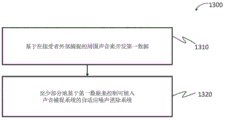
In view of the above, embodiments include a method as represented by the flow chart of fig. 3C. In particular, fig. 3C represents a method 1300 that includes a method act 1310, the method act 1310 requiring development of first data based on ambient sound captured externally to the recipient. In this regard, in an exemplary embodiment, the first data may correspond to data from either path 2 or path 3. More specifically, in an exemplary embodiment, the first data may be developed by operating the hearing prosthesis system 400 in an external microphone-based mode. That is, in an alternative exemplary embodiment, the first data may be developed by operating the hearing prosthesis 400 in an implantable microphone based mode, wherein the external microphone 427 is operating as a data collection device, wherein the hearing perceptions invoked by the hearing prosthesis system 400 are based on the output of the implantable microphone 411, and not on the output of the external microphone 427. Still further, in at least some embodiments, the external microphone 427 need not be a device that is part of the hearing prosthesis system 400 or that is in communication with the hearing prosthesis system 400. Method act 1310 may be performed with any data based on ambient sound captured outside the recipient from any source, at least providing that the data may be later temporarily or otherwise sufficiently linked with other data (e.g., data related to one or more of signal paths 1, 4, 5, or 6) to enable the teachings detailed herein and/or variations thereof with respect to developing an algorithm for the adaptive noise cancellation subsystem 460 that takes into account the above-noted deficiencies with respect to the transducer system 480 and/or the above-detailed transfer function offsets.
The first data may be stored by the control unit 440 or any other component of the hearing prosthesis 400. Indeed, as noted above, in alternative embodiments, the first data (e.g., data from path 3, data from path 2) may alternatively and/or additionally be transmitted from the external microphone 427 and/or from the hearing prosthesis 400 to an external storage device separate from the hearing prosthesis system 400 (e.g., in a manner that accompanies a telemetry system utilized with the implanted medical device). Any device, system, and/or method that collects data may be used in the practice of method act 1310.
The method 1300 further includes a method act 1320, the method act 1320 requiring control of an adaptive noise cancellation system (e.g., the subsystem 460) of the implantable sound capture system based at least in part on the first data. In this regard, by way of example only, and not limitation, because the algorithm developed based on the evaluation of signal path 2 or the comparison of signal path 1 to signal path 3 (or one or more of the other signal paths) as detailed above to accommodate the flaw/transfer function offset associated with the transducer system 480 is based on data based on ambient sound captured external to the recipient, operation of the adaptive noise cancellation subsystem 460 with such developed algorithm corresponds to performing method action 1320.
In view of the foregoing, exemplary embodiments include a system, such as a hearing prosthesis system 400, that includes a noise cancellation subsystem (e.g., subsystem 460 of fig. 3B) configured to at least partially cancel a body-conducted noise component from a first signal that is the output of an implantable microphone (e.g., microphone 412). In an exemplary embodiment, the first signal includes the aforementioned body-conducted noise component and ambient sound component. The system is further configured to at least partially cancel the body-conducted noise component using a first algorithm, the first algorithm being based on a second signal that precedes (e.g., exists before) the first signal in time, the second signal being based on a captured sound that is at least one of: (i) completely isolated from body-conducted noise, or (ii) composed entirely of ambient sound. In an exemplary embodiment, the first signal is based on a captured sound, the captured sound being at least one of: (i) no body-conducted noise, or (ii) consists entirely of ambient sound. In an exemplary embodiment, the signal may correspond to, for example, a path 1 signal. It is further noted that the signal of path 2 may also correspond to the second signal. Indeed, the signal of path 2 is based at least in part on a signal that includes a body-conducted noise component (which is based on the signal, although cancelled from another signal). However, the path 2 signal is also based on a captured sound that, at least in some embodiments, meets at least one of these 2 requirements (the signal is based on a captured sound that is completely isolated from body conducted noise, or the signal is based on a captured sound that is completely composed of ambient sound).
As noted above, the hearing prosthesis is configured to set the operating parameters of the noise cancellation system based on input from the external microphone 427. In an exemplary embodiment, adjustment data (e.g., which may include compilation of pseudo filter coefficient settings, filter adjustments, etc.) corresponding to how the control algorithm used by the control unit 440 will adjust the filter 450 to eliminate body-conducted noise components to achieve a solution or otherwise reduce the effect of the aforementioned deficiency/transfer function offset on the transducer system 480 may be developed or otherwise obtained and used to set or otherwise identify operating parameters. In some exemplary embodiments, the operating parameters are set in a manner that accompanies the implementation of the error correction regime (which may also be developed in a manner that accompanies the development of such a regime). That is, in an exemplary embodiment, data based on input from a microphone external to the recipient may be used to determine an error in the transducer system 480 and/or to determine a correction needed to compensate for the error in the transducer system 480. The resulting operating parameters of noise cancellation subsystem 460 (e.g., parameters of an algorithm controlling filter 450 of filter control unit 440) are then used by filter control unit 440 when noise cancellation subsystem 460 operates to cancel body noise.
In at least some example embodiments, the resulting operating parameter is a static operating parameter. For example, the same operating parameters are used regardless of the dynamic environment of the hearing prosthesis system 400. Note that while this resulting operating parameter may be a static parameter, the noise cancellation subsystem 460 may still operate in a dynamic manner (e.g., the noise cancellation subsystem 460 may be an adaptive noise cancellation subsystem in which the operating parameters used to correct the above-noted problem (error) in the transducer system 480 are static). Alternatively, in an exemplary embodiment, the operating parameter may be in the form of a function, wherein the operating parameter is varied based on varying the input according to some form of algorithm. Still further, in an exemplary embodiment, the operating parameter may be an operating parameter that varies in response to changing dynamic environments of the hearing prosthesis system 400, and not necessarily a particular function. By way of example only, and not limitation, a table may be developed and stored in the hearing prosthesis 400 that correlates inputs from one or more of the signal paths 1, 4, 5, and/or 6 with correction/adjustment data to be used by the filter control unit 440 that controls the filter 450 to achieve noise cancellation that addresses or otherwise accounts at least in part for the deficiencies noted above associated with the transducer system 480. During use of noise cancellation subsystem 460, when the input in control unit 440 corresponds to an exemplary situation corresponding to an input cataloged in a look-up table (accurately, statistically, and/or extrapolatively), control unit 440 may utilize the corresponding adjustment data on the look-up table as a basis for controlling filter 450. These are merely some exemplary ways to implement the noise cancellation regime for the above-identified deficiencies associated with the transducer system 480. Any apparatus, system, and/or method that may be used to enable a hearing prosthesis to at least partially cancel noise, including body conducted noise, using an algorithm based on the output of an external microphone (whether or not it is part of the hearing prosthesis) may be used in at least some embodiments.
Also, as detailed above, embodiments disclosed herein generally focus on adaptive noise cancellation systems, where the control unit 440 utilizes feedback (the feedback loop represented by path 1 in fig. 3B) to control the adjustment of the filter 450 based on the feedback. However, in alternative embodiments, the noise cancellation system need not be adaptive, or at least not a system that relies on a feedback loop, at least not in all cases to cancel noise, such as body conduction noise. In contrast, in an exemplary embodiment, the noise cancellation system may be a system configured to adjust the filter 450 (including setting the filter 450) without relying on a feedback loop. More specifically, in an exemplary embodiment, controller 440 may be configured to control tunable filter 450 based on signals output by implantable microphone 412 and/or accelerometer 470. In this regard, while the adaptive noise cancellation system may adaptively adjust the filter 450 (or more precisely, adjust the adjustment of the filter 450 based on feedback of the signal obtained by the summer 430) using a feedback loop, in an exemplary embodiment of the noise cancellation system, the adjustable filter 450 may be controlled without using a feedback loop.
By way of example only, and not limitation, a data table may be developed and stored in hearing prosthesis 400 that correlates outputs of microphone 412 and/or accelerometer 470 (in front of and/or behind filter 450) with corresponding control outputs of control unit 440 that controls filter 450 to enable noise cancellation that addresses or otherwise accounts at least in part for the above-noted deficiencies associated with transducer system 480. When control unit 440 identifies a given situation based on an input from one or more of signal paths 4, 5, or 6 corresponding to an input present in the look-up table (accurately, statistically, and/or extrapolatively), control unit 440 selects a corresponding control output associated with the input and adjusts filter 450 accordingly. In this regard, in an exemplary embodiment, the noise cancellation subsystem 460 may operate entirely based on an algorithm that does not utilize feedback from the noise cancellation subsystem. That is, in the exemplary embodiment, the noise cancellation is configured to switch between modes that utilize a feedback system and modes that do not utilize a feedback system (between algorithms and/or parameter sets) as the case may be at system 460.
Further, it is noted that in at least some embodiments, the noise cancellation subsystem 460 does not dynamically change the filter 450 to address deficiencies associated with the transducer system 480. In contrast, in the exemplary embodiment, filter coefficients 450 are set based on the above-noted evaluations and comparisons, which at least partially mitigates deficiencies associated with transducer system 480. In this regard, at least some embodiments require a noise cancellation subsystem that is not an adaptive noise cancellation subsystem, but rather a noise cancellation subsystem based on data developed in a data collection mode.
In at least some example embodiments, there are hearing prostheses with noise cancellation subsystems configured to at least partially cancel body conduction noise from signals output by an implantable microphone using an implantable accelerometer, wherein the implantable accelerometer is isolated from energy derived from ambient sound in an imperfect manner (i.e., the accelerometer will receive more than zero percent, but limited, energy from ambient sound received by the implantable microphone due to natural physical constraints associated with engineering, design, and implementation) that is captured by the implantable microphone used by the hearing prosthesis to tune the hearing perception. The noise cancellation subsystem is configured to reduce the effect of this imperfect isolation of the accelerometer using signal filtering by removing at least about 50%, 55%, 60%, 65%, 70%, 75%, 80%, 85%, 90%, 91%, 92%, 93%, 94%, 95%, 96%, 97%, 98%, and/or about 99% or more (e.g., about 100%) of the components of the energy of the ambient sound in the output signal of each frequency band of the accelerometer or any value or range of values therebetween in increments of about 0.1% (e.g., 67.5% to 99.9%, at least about 90.3%, etc.) (which may be the same over the entire frequency band or may vary over the entire frequency band), relative to the case without such signal filtering. In an exemplary embodiment, signal filtering is achieved by controlling the filter according to the teachings detailed herein.
In at least some example embodiments, the noise cancellation subsystem is configured to utilize signal filtering to reduce the components of energy derived from ambient sounds in the output of the accelerometer such that the signal output from adder 430 and/or output from switch 434 is at least about 80%, 85%, 90%, 91%, 92%, 93%, 94%, 95%, 96%, 97%, 98%, and/or about 99% or more (e.g., about 100%) or any value or range of values therebetween in increments of about 0.1% in combination with the signal output directly from the external microphone that is part of the hearing prosthesis based on the exact same ambient sounds that created the energy captured by the accelerometer. In an exemplary embodiment, signal filtering is achieved by controlling the filter according to the teachings detailed herein.
As noted above, at least some example embodiments of the teachings detailed herein may be used to address or otherwise compensate for deficiencies associated with the transducer system 480. Alternatively and/or additionally, at least one example embodiment may be used to address or otherwise compensate for one or more phenomena associated with implementation of the noise cancellation system of fig. 2-3B, whether or not the sometimes-occurring paths 2-6 are utilized. This phenomenon will now be described (along with the framework of the system associated with the phenomenon), for which the teachings detailed herein may have practical value in some embodiments.
Fig. 4 presents a functional diagram of an exemplary adaptive filter arrangement utilizing an adaptive filter that is adapted based on the current operating conditions (e.g., operating environment) of the implantable hearing prosthesis. It is noted that the teachings detailed herein and/or variations thereof can be combined with some or all of the teachings of U.S. patent application publication No.2012/0232333 issued by inventor Scott alan Miller at 9/13 of 2012. In this regard, at least some embodiments include apparatus, systems, and/or methods that utilize one or more or all of the teachings of U.S. patent application publication No.2012/0232333 in combination with one or more or all of the teachings detailed herein. It is further noted that, in at least some embodiments detailed herein, the adaptive noise cancellation systems and methods disclosed in the aforementioned U.S. patent application may be utilized with the hearing prosthesis systems detailed herein.
There are some situations: such operating conditions are typically not directly observable/even though the operating conditions may be able to be observed directly by utilizing certain components that may not be present in the hearing prosthesis, not. That is, the operating conditions form a latent parameter. Thus, the system is operable to estimate the latent parameters for the purpose of adapting to current operating conditions. In other words, the system utilizes a latent variable adaptive filter.
In an exemplary embodiment, the Latent Variable Adaptive Filter (LVAF) is computationally efficient, converges quickly, can be easily stabilized, and is robust in its performance in the presence of correlated noise. It may be based on an IIR filter, rather than adapting all coefficients independently, it may exploit the functional dependence of the coefficients on the latent variable. In statistics, a latent variable is one that is not directly observable, but can be inferred through observation of the system. Examples of latent variables are the thickness of the tissue above the microphone and/or the wave propagation properties through the tissue above the microphone. In at least some embodiments, this is not measured directly, but inferred from changes in the microphone motion sensor (i.e., min/acc) transfer function. Another hidden variable may be a user "gesture". It has been pointed out that some users of implantable hearing instruments experience difficulty in feedback when turning left or to the left (typically one direction is worse) if the (non-adaptive) cancellation filter has been optimized with a forward-facing recipient. A gesture may be assumed to have one value at one "extreme" position and another value at a different "extreme" position. "extreme" is flexible in the sense that in this case; it may mean at the extremes of posture, or it may mean far more than modest posture changes that still generate different amounts of feedback to the recipient. The pose in this case may be a Synthetic Hidden Variable (SHV) because the actual value of the variable is arbitrary; importantly, the value of the hidden variable varies from measurement to measurement. For example, the value of SHV for a gesture may be "+ 90" for a recipient that is always facing right and "-90" for a recipient that is always facing left, regardless of whether the recipient actually rotated the entire 90 degrees from the front. The actual values of SHV are arbitrary and may be "-1" and "+ 1", or "0" and "+ 1", if such a range results in computational simplification.
Note that while the teachings detailed herein relating to parameters are described with respect to embodiments in which the parameters are gesture parameters, the parameters may be other parameters. Indeed, in exemplary embodiments, the noise cancellation subsystem and/or variations thereof detailed herein may track any impairments of the system, at least so long as the presence of the impairments can be detected. For example, the damage may be due to, for example, an overflow of an internal register, which may, in some cases, cause oscillations in the output.
In terms of gestures, in an exemplary embodiment, physical parameter(s) are assigned to SHVs, such as the angle the recipient turns from facing forward. However, there are other situations where variables are truly hidden. An example may be that the recipient internally activates a muscle group, which may or may not have any outward appearance. In this case, if the mandatory and non-mandatory spasm conditions affect the feedback differently, these two conditions may be given values of "0" and "+ 1" or some other arbitrary value. One of the advantages of using SHV is that only the vibration/motion response of the microphone assembly needs to be measured, it may be practical not to measure the actual hidden variable. That is, the hidden variable(s) may be estimated and/or inferred.
As shown in fig. 4, the adaptive system may utilize two adaptive cancellation filters 90 and 92 instead of one fixed cancellation filter. The cancellation filters are identical and each cancellation filter 90, 92 may comprise an adaptive filter (not shown) for adjusting the motion accelerometer signal Acc to match the microphone output signal Mic to produce an adjusted or filtered motion signal. In addition, each cancellation filter may include a summing device (not shown) for subtracting the filtered motion signal from the microphone output signal to produce cancelled signals that are estimates of the microphone's response to a desired signal (e.g., ambient acoustic signals). Each adaptive cancellation filter 90, 92 estimates a latent variable "phi", which is a vector variable representing one or more dimensions of a posture or other variable operating condition that changes in the recipient, but whose value is not directly observable. The estimate of the latent variable phi is used to set the coefficients of the cancellation filter to cancel microphone noise caused by, for example, feedback and biological noise. That is, all of the coefficients of the filters 90, 92 depend on the latent variable phi. After cancellation, one, two or a combination of the cancelled microphone signals (essentially acoustic signals) are passed on to the rest of the hearing instrument for signal processing.
In order to determine the value of the latent variable phi that provides the best cancellation, the coefficients of the first cancellation filter 90 are set to values based on an estimate of the latent variable phi. In contrast, the coefficients of the second cancellation filter 92 (referred to as the scout cancellation filter 92) are set to estimated values based on the latent variable phi plus (or minus) a predetermined value delta. Alternatively, the coefficients of the first filter 90 may be set to the value of the latent variable plus delta and the coefficients of the second filter may be set to the value of the latent variable minus delta. In this regard, the coefficients of the second adaptive filter 92 are slightly different from the coefficients of the first filter 90. Thus, the first and second cancelled signals or residuals output by the first adaptive cancellation filter 90 and the second adaptive cancellation filter 92 may have slightly different energies. The residuals (which are the non-cancelled portions of the microphone signal outside each cancellation filter 90, 92) are compared in a comparison module 94, and the difference of the residuals is used by a Phi estimator 96 to update the estimate of Phi. Thus, the process may be repeated until the value of phi is iteratively determined. In this regard, phi may be updated until the residual values of the first and second cancellation filters are substantially equal. At such times, either of the canceled signals may be used for subsequent processing, or the canceled signals may be averaged together in summing device 98 and then processed.
Adjusting the latent variable phi based on a comparison of the residuals of the cancelled signals makes it possible to quickly adjust the cancellation filter for the current operating conditions of the implantable hearing instrument. To further speed up the process, it may be practical to make large adjustments (i.e., strides) to the latent value phi. For example, if the range of phi is known (e.g., 0 to 1), an initial mid-range estimate of phi (e.g., 1/2) may be used as the first estimate. Alternatively, the initial value of phi may be set to 0 (which may correspond to a relaxation gesture for embodiments where phi is gesture-related), and the iteration proceeds from these values.
Likewise, the step size of the adjustment of phi may be relatively large (e.g., 0.05 or 0.1) so that the filter coefficients may converge quickly to substantially remove noise from the microphone output signal in response to changes in operating conditions.
To implement the system of fig. 4, in at least some embodiments, a filter is generated in which the filter coefficients depend on latent variables associated with variable operating conditions/environments of the implantable hearing instrument. Fig. 5-8 provide an overview of how the dependence of the adaptive filter on changing operating conditions may be established in at least some embodiments.
Fig. 5 illustrates the overall process for generating a filter. Initially, the process requires two or more system models to be generated for different operating environments. For example, the system model may be generated when the recipient is looking to the left, looking straight ahead, looking to the right, and/or leaning. The system model may be generated as discussed above and/or as discussed in U.S. patent application publication No.20120232333 and/or according to any practical method. Once such system models are generated in act 310, parameters for each system model may be identified in act 320. In particular, parameters that vary between different system models, and thus different operating environments, may be identified at act 320.
For example, each system model may include multiple dimensions. Such dimensions may include, but are not limited to, gain, real poles, real zeros, and complex poles and zeros. Further, it will be appreciated that the complex poles and zeros may include radii as well as angular dimensions. In any case, a set of these parameters that vary between different models (i.e., and different operating environments) may be identified. For example, a complex radius for each system model may be determined, as well as a complex angle and gain (i.e., three parameters), which show the variation for different operating conditions. For example, FIG. 6 illustratesIllustrating a plot of a unit circle in the "z" dimension. As shown, for four system models M1To M4Are projected onto the plot. It can be seen that there is some variation between the parameters of the different system models. However, it will be appreciated that other parameters may be selected. In at least some embodiments, the selected parameters are selected in a manner such that they vary between system models, and the variation is caused by a change in the operating conditions of the implantable hearing instrument.
Once the variable parameters are identified in act 320, they may be projected into a subspace (act 330). In the present arrangement where multiple parameters are selected, this may require principal component analysis to be performed on the selected parameters in order to reduce their dimensionality. In particular, in the present embodiment, principal component analysis is performed to reduce the dimensionality to one dimension so that a straight line can be fit to the resulting data points. (see, e.g., FIG. 7.) thus, this data may represent operating environment changes or latent variables for the system. For example, in the present arrangement where four system models are based on four different gestures of the user, the changes may represent gesture values. Further, the plot may define a range of latent variables. That is, a line fit to the data may define the limits of the latent constant. For example, a first end of a straight line may be defined as a zero point and a second end of the straight line may be defined as a one. At this point, latent variables for each system model may be identified. Further, the relationships of the remaining parameters of each system model may be determined with respect to the latent variables of the system model (e.g., act 340). For example, as shown in FIG. 8, a linear recursive analysis of all real poles of the four system models for the latent variable may be projected. In this regard, the relationship of each parameter (i.e., real poles, real zeros, etc.) with respect to the latent variable may be determined. For example, the slope of the resulting linear recursion can be used as the sensitivity for each parameter. Thus, this relationship between the parameter and the latent variable is determined, and this information may be used to generate a coefficient vector, which may be implemented with the cancellation filters 90, 92 of the system of FIG. 4 (act 350). As will be appreciated, the coefficient vector will depend on the latent variable. Thus, by adjusting a single value (latent variable), all coefficients can be adjusted.
It is noted that in some embodiments, cancellation algorithms in accordance with the above teachings and/or variations thereof may be affected by own voice body conducted noise in a detrimental manner. That is, bone conduction/body conduction sounds originating from/caused by vocal cord vibrations of the recipient's own voice, hereinafter, for convenience of language, are often simply referred to as "own voice body conduction noise phenomenon" or "own voice phenomenon", and unless otherwise specifically indicated to the contrary, the latter phrase corresponds to noise caused by the recipient's own voice being conducted through tissue (e.g., bone) to the implanted microphone. In an exemplary scenario, this is caused by the relatively large amount of acceleration signals present in the microphone channel and the accelerometer channel. As a result, in some cases, the noise cancellation algorithm may not respond appropriately to the own speech signal, ramping up the state variables associated with the parameters (e.g., gesture parameters, etc.) to a larger value, eventually reaching the allowable limits of operation. After the native speech phenomenon ceases, the parameters typically return to their appropriate values.
The acceleration transfer function of accelerometer 470 is fixed for a given parameter (e.g., a posture parameter) relative to the acceleration transfer function of microphone 412. In some cases, there may be a deviation from the fixed relationship when stimulated by own voice in some recipients. As a result, the feedback cancellation algorithm seeks the wrong set of parameters as long as the own speech excitation continues. If a detrimental situation occurs anyway, it usually occurs during loud and harmonic phonemes (e.g. vowels), but is different from non-linear problems such as saturation of the signal chain. More specifically, fig. 9 depicts a plot of microphone 412(MIC) ADC output and accelerometer 470(ACC) ADC output versus time for a situation where the own voice phenomenon causes the algorithm to seek the wrong set of parameters. It can be seen that the MIC and ACC ADC values are not close to the saturation level, which would be about 32,767 to-32,768, and the graph does not show any of the classical clipping that might be expected.
The following exemplary embodiments are directed to elimination algorithms that utilize gestures as parameters.
Fig. 10 depicts a graph of phi versus time (in each frame of 16kHz 1 samples) for the normal evolution of the pose variables phi1 and phi2 in the case that the effect of own voice body noise does not affect the algorithm or at least the algorithm is able to cope with the effect of own voice body noise. The limits for phi1 and phi2 are +/-1. It can be seen that the values phi1 and phi2 deviate from the initial value of zero, but are generally far from the limit (+/-1).
Fig. 11A also depicts a plot of phi versus time for the case where the effect of the own voice body noise affects the algorithm in a way that the algorithm is affected in a detrimental way. More specifically, fig. 11A depicts a graph of the situation where the phoneme "EEEEEE" is pronounced by the recipient in a relatively loud manner. It can be seen that the effect of the own-voice body noise ramps the values of phi1 and phi2 from the initial value of zero to the limit of 1, and remains there, or relatively close thereto, as long as the recipient is speaking the aforementioned phoneme.
As noted above, the own phonetics that cause the value of phi to ramp up towards the limit may have a detrimental effect on the noise cancellation algorithm. For example, the native speech phenomenon prevents the recipient from receiving the practical effects of feedback cancellation, at least partially and/or completely, while speaking. This may be because the value of phi is unstable and may reach a limit in some cases. In some cases where the real-time value of phi is used for noise cancellation, the ramped phi value may potentially cause noise in the system. Furthermore, due to the time constraints of the feedback correction algorithm used to improve the algorithm's resistance to noise, the own-voice phenomenon takes time to pull the parameters away from their correct values. This necessarily results in that the algorithm recovery may also take time, sometimes about the same amount of time, sometimes more time, sometimes less time (e.g., roughly tracing back a trajectory caused by the native phonetics may take about the same time). For example, with respect to FIG. 11A, the time for ramping up is about 37.5ms, and the time for recovery will also be about 37.5 ms. In case the entire practical effect of feedback cancellation is not available to the recipient, this may correspond to about 75 ms.
According to exemplary embodiments, there are apparatuses, systems, and methods that address, at least in part, this phenomenon of self-noise. More specifically, in the exemplary embodiment, the parameters are developed based on data obtained from external microphone 427 because external microphone 427 is not implanted in the recipient, so external microphone 427 produces an output that is not affected by the phenomenon of spontaneous noise associated with body conducted noise. Data from the external microphone is used to develop an algorithm that controls the adaptive noise cancellation subsystem 460 by limiting the adaptation of the subsystem based on the data from the external microphone such that the adaptive noise cancellation subsystem 460 is prevented from reaching the limits noted above (either by stopping the adaptation at a location before the limits are reached (e.g., freezing the filter), or by implementing another algorithm for the adaptive system that will not result in reaching the limits, or by some other mode that may enable the teachings detailed herein and/or variations thereof to be implemented). In this regard, in a manner similar to the development of the control parameters developed above, when a hearing prosthesis is utilized in an external microphone-based mode, in which the adaptive noise cancellation subsystem 460 operates, but whose output is not used to invoke hearing perception (data collection mode), the signal path 1 may be compared to the signal path 3 and/or the output of the signal path 2 may be evaluated. Situations where the own voice body noise content of the signals from microphone 412 and/or accelerometer 470 is sufficient to cause the above-noted detrimental phenomena may be identified by evaluating the input from path 2 in any manner that would enable evaluation of the input from path 2. By way of example, and not limitation, a large (statistically significant/significant compared to empirical data) and/or sudden and/or temporally short change from a typical input from path 2 may be an indication that the above self-voiced body noise phenomenon has occurred. Alternatively or in addition, the input from path 1 may be compared with the input of path 3 (or from any other relevant path (s)). Based on the foregoing evaluation and/or comparison, an algorithm is then developed that prevents filter control unit 440 from adjusting filter 450 outside a given range, thereby preventing the own voice body conducted noise from significantly adversely affecting noise cancellation subsystem 460.
Thus, in an exemplary embodiment, the above-noted actions of limiting the adaptation of the noise cancellation subsystem include preventing the filter of the system from being adapted to have certain coefficients based on data developed based on ambient sound captured by the external microphone.
Along with the above teachings associated with developing look-up tables and/or functions for controlling noise cancellation subsystems, exemplary embodiments include: pseudo-noise cancellation subsystem operating parameters are obtained that indicate how the subsystem should operate to cancel body conducted noise, and operation of the system is limited to the pseudo-noise cancellation system operating parameters. In an exemplary embodiment, the pseudo noise cancellation subsystem operational parameters may correspond to/be used in an algorithm in which extreme filter values are identified based on data received during the external microphone based mode, taking into account how filter 450 should be adapted to output a signal corresponding to or lacking the signal that would be output if the inputs into filter control unit 440 via the various paths corresponded to perfect or at least more perfect operation of transducer 480. Alternatively and/or in addition, the pseudo noise cancellation subsystem operating parameter may be a limit on the filter. In an exemplary embodiment, the pseudo-noise cancellation subsystem operating parameter may be a filter coefficient value that is prohibited from being used by the hearing prosthesis system 400. In at least some example embodiments, the pseudo-noise cancellation subsystem operating parameter may be any parameter based on data developed with the above detailed operation of the hearing prosthesis system 400 in an external microphone-based mode (where the noise cancellation subsystem 460 is in a data collection mode that may be utilized in the operation of the hearing prosthesis system 400 that will avoid the above-noted self body noise phenomenon from occurring). Thus, in an exemplary embodiment, the act of controlling an adaptive noise cancellation system of the implantable sound capture system based at least in part on the first data comprises at least one of: the coefficients of the adaptive filter of the adaptive noise cancellation system are limited to pseudo-adaptive filter coefficients or prevented from having values exceeding the extreme values of the pseudo-adaptive filter coefficients.
In view of the foregoing, in an exemplary embodiment, the act of obtaining the pseudo-noise cancellation system operating parameters includes comparing data based on an output signal of an implantable microphone of the implantable sound capture system based on sound captured by the implantable microphone (e.g., an input from path 1 or path 4 or an output from summer 430 into summer 432) to a signal based on ambient sound captured outside the recipient (e.g., an input from path 3 or an input into summer 432), where the sound captured by the implantable microphone originates from the same sound source as the sound source originating the sound captured outside the microphone (since the sound captured by external microphone 427 is the same sound impinging on the recipient's skin that causes energy to propagate through the recipient's skin to transducer system 480). Further, the exemplary method includes developing pseudo-adaptive filter coefficients based on a comparison, where the comparison may correspond to a summation at summer 432, the resulting input to path 2 being the result of the comparison.
It is noted that in an exemplary embodiment, the above-noted method further comprises configuring the hearing prosthesis system 400 with the above-noted developed pseudo noise cancellation system operating parameters and/or pseudo adaptive filter coefficients. This has the corollary that in an exemplary embodiment, there is a hearing prosthesis system configured with the above-noted developed pseudo noise cancellation system operating parameters and/or pseudo adaptive filter coefficients in accordance with the teachings detailed herein and/or variations thereof.
Still further, by way of example only, and not limitation, in at least some embodiments, operating parameters (such as, for example, pseudo noise cancellation system operating parameters) may be developed using one or more or all of the methods detailed above and/or variations thereof or other methods (any of which may be utilized) that take into account short-term variations in ambient conditions of the implanted transducer system 480 when applied to the noise cancellation subsystem 460. Indeed, as understood from the above, the pseudo-operational parameters may be used to compensate for changes in posture, such as where the recipient turns his or her head to the side, which consequently results in different tightening conditions on the skin that change the response of the noise cancellation subsystem to ambient sounds and/or body conducted noise. Still further, by way of example only, and not limitation, a recipient of the hearing prosthesis system 400 may be exposed to a situation in which the recipient's surrounding environment changes. For example, the recipient may change pressure altitude (e.g., in the case of a recipient flying in a modern pressurized commercial jet aircraft), and so forth. In such an exemplary situation, this may change the preload on the membrane/diaphragm of the transducer system 480. This means that, in at least some instances, the settings of the filter 450 should be different to achieve a noise cancellation effect (e.g., a noise cancellation setting with utility value on sea level) that has a utility value comparable to the situation before the recipient's ambient environment changes (resulting in a change in preload on the membrane/diaphragm of the transducer system 480).
Utilizing the methods detailed above and/or variations thereof or other methods to develop the pseudo-operating parameters after the recipient has changed his or her ambient environment, the noise cancellation subsystem 460 may at least partially account for the results of the preload change on the film/diaphragm by utilizing those developed pseudo-operating parameters during the time period that the recipient is in the new ambient environment. By way of example only, and not limitation, in an exemplary embodiment, a recipient may board an airliner and shortly after takeoff, after the aircraft has reached a pressure altitude of 8,000 feet or more (or whatever is used by the applicable fuselage manufacturer as the pressure in the passenger cabin), for example, the recipient may utilize the hearing prosthesis system 400 in an external microphone-based mode (with the noise cancellation subsystem 460 in a data collection mode) to develop pseudo-operational parameters that may be automatically developed by the hearing prosthesis system 400 and/or automatically developed with additional components (e.g., a portable laptop configured to connect to the hearing prosthesis 400 that has more processing power than the hearing prosthesis 400 so the algorithm is developed in the portable laptop and then communicated to the hearing prosthesis system 400), these pseudo-operating parameters may be utilized by the hearing prosthesis system 400 during subsequent actions that invoke hearing perceptions based on inputs implanted in the microphone 412. This may have utility value in that it may improve the performance of the adaptive noise cancellation subsystem 460 relative to the case of utilizing an algorithm based on sea level models/sea level data. This may also have practical value, i.e., the detrimental effects associated with the own body noise noted above may still be avoided by utilizing the limits on filter 450. In this exemplary situation, the recipient may utilize newly developed parameters on board the aircraft when the aircraft is at cruise altitude/when the pressure in the passenger cabin is a given boost for cruise. At the end of the flight, the recipient may then switch the hearing prosthesis 400 back to the original parameters that existed prior to the flight or other parameters that may be developed utilizing the teachings detailed herein and/or variations thereof. That is, in an alternative embodiment, the hearing prosthesis system 400 may be configured to automatically perform this operation upon determining that the environment prompts a parameter change/prompts that development of a new parameter has ceased/the recipient is no longer in the environment. As a corollary of this, in at least some embodiments, the hearing prosthesis system 400 is configured to determine that a given environment has changed, thus automatically performing different parameters developed with the hearing prosthesis in a data collection mode, the parameters developed in accordance with the teachings detailed herein and/or variations thereof.
In this regard, exemplary embodiments require real-time adaptive calibration or at least closest temporal adaptive calibration of the implantable sound capture system, the difference between the two being that in the latter, data may be obtained with an external microphone during a first time period, and then data may be obtained with an implantable microphone during a second time period, the two time periods being different (completely separate, overlapping) from one another, wherein the first and second time periods do not necessarily indicate a data collection order. The latter may have a practical value in situations where processing power is limited and where the environment of the first and second time periods may be controlled. (this will be described in more detail below.)
Some example calibration methods and systems for implementing such methods may enable a calibration activity to equalize the frequency response of an implantable microphone to match the frequency response of an external microphone. This may enable adaptive calibration to be used to reduce distortion of the implanted microphone due to environmental changes, both chronic changes in the recipient (such as fibrous tissue growth, weight gain, thinning of the skin, etc.) and drastic changes (such as wearing a hat, changing the hairstyle, height changes, etc.).
More specifically, because the implanted microphone system is implanted, the energy received by the system due to ambient sounds is distorted by the recipient's body structure. Various factors affect distortion. For example, the thickness of the flap, the degree of fibrous tissue growth adjacent the microphone, the number and location of hairs on the scalp, etc. may alter the distortion. While the above embodiments have focused at least in part on body noise and its noise cancellation, the following focuses on more general distortion phenomena. Consistent with the above, the external microphone may be used as a reference for calibrating the implanted hearing prosthesis, since the external microphone may be considered as a true representation of the actual sounds of the surroundings (e.g. what the recipient of the hearing prosthesis wants to hear). In an exemplary embodiment, the external microphone used as a reference has a known frequency response, and/or has been calibrated during production, and/or is of a known design with a stable frequency response. Exemplary embodiments entail comparing the output of an external microphone with the output of an implanted microphone to enable calibration and/or diagnostic features as will now be described in detail.
Continuing with the aforementioned airliner journey scenario in which the recipient changes pressure altitude (and somewhat similar to, although in perhaps less drastic situations, the recipient lives in mountainous areas where the recipient's pressure altitude changes frequently as a result of travel), the teachings detailed herein may have utility value in addressing the phenomena associated with implantable microphones that do not have a pressure equalization system (e.g., do not have a system similar to a human's eustachian tube system). In this regard, the implantable microphone is hermetically sealed from the surrounding environment, wherein the diaphragm and/or membrane form a portion of an outer surface of the implantable microphone. In this exemplary embodiment, the microphone element implanted in the microphone is inside the sealed housing of the implantable microphone in pressure communication with the diaphragm/membrane. The internal pressure of the microphone does not change (because the gas inside is at a constant temperature, a fixed volume) or at least does not change by a perceptible amount as the recipient's ambient pressure changes. Instead, the external pressure changes due to the change in altitude (which, of course, has the consequence that the pressure changes due to being under water or the like). All things being equal, this biases the diaphragm/membrane in a particular direction, which changes its frequency response and can therefore distort the sound picked up by the hearing prosthesis.
Utilizing the teachings detailed herein to obtain first and second data from respective external and implantable microphones, the first and second data can be used to compensate for the fact that the frequency response of the diaphragm/membrane has changed in accordance with the teachings detailed herein when calibrating the sound capture system. Note that while embodiments utilizing this calibration may be implemented via the noise cancellation subsystem, alternative embodiments may be implemented for systems other than the noise cancellation subsystem. Thus, while the embodiments detailed herein are generally described in terms of noise cancellation systems, the teachings detailed herein and/or variations thereof may be implemented with different types of systems (e.g., systems configured to specifically enable the calibration techniques detailed herein). Thus, unless otherwise specified, any disclosure of a noise cancellation system/subsystem herein corresponds to a disclosure of a more general system and/or a specific system (e.g., calibration system, calibration/noise cancellation subsystem, etc.), provided that the teachings detailed herein and/or variations thereof can be implemented. Any devices, systems, and/or methods that can enable the teachings detailed herein and/or variations thereof to be implemented can be used in at least some embodiments. This entails that although the embodiments detailed herein generally focus on body noise cancellation, the teachings detailed herein are also applicable to sound management techniques, regardless of the presence or absence of body noise.
Accordingly, in an exemplary embodiment, there is a hearing prosthesis comprising an implantable microphone and a sound management system (e.g., a noise cancellation subsystem, a calibration subsystem, etc.), wherein the hearing prosthesis is configured to set at least one operating parameter of the sound management system based on input from a microphone external to a recipient of the implantable microphone. In an exemplary embodiment of this embodiment, setting the at least one operating parameter at least partially compensates for a changed frequency response of the implanted microphone diaphragm and/or one or more other changes in the system that affect the perceived sound. In an exemplary embodiment, the at least one operating parameter is changed by adjusting a filter of the sound management system. In an exemplary embodiment, the at least one operating parameter is changed by adjusting a gain of the sound management system. Further, by way of example only, and not limitation, management of frequency channels may be adjusted. For example, certain frequency channels may be attenuated and other frequency channels emphasized relative to the pre-change situation in order to calibrate the sound management system to make the adjusted hearing perceptions more consistent with if the hearing perceptions were based on an external microphone rather than an implantable microphone.
Still further, in an exemplary embodiment, there is a hearing prosthesis configured to enable a recipient to initiate a calibration routine that will calibrate a sound management system based on data from an external microphone. Alternatively and/or additionally, in an exemplary embodiment, there is a hearing prosthesis configured to automatically initiate a calibration routine that will calibrate a sound management system based on data from an external microphone. In an exemplary embodiment, the hearing prosthesis may be configured to periodically obtain data from the external microphone, and the hearing prosthesis may automatically enter a calibration routine when it is determined that the deviation between the hearing percepts tuned up with the implantable microphone and those to be tuned up with the external microphone has reached a certain level. Alternatively and/or in addition, the hearing prosthesis may provide an indication to the recipient that the calibration may be of practical value or at least more practical value in a given instance relative to what was in the preceding time period in time. Alternatively and/or in addition thereto, the hearing prosthesis may be configured to provide data to a third party indicating that the hearing prosthesis has experienced a change in its surroundings that is of interest. Such ambient changes may have to include fibrous tissue growth, weight gain or weight loss, etc. over the microphone membrane/diaphragm. It is further noted that the hearing prosthesis may be configured to utilize the techniques detailed herein to indicate that the hearing prosthesis itself has experienced a change (or both). That is, rather than the ambient environment changing, the implantable microphone may become damaged or the like (due to the impact), such that, for example, the transfer function of the diaphragm/membrane has changed. It is further noted that, in at least some example embodiments, it is not necessary for the hearing prosthesis to indicate the type of change that has occurred or to otherwise provide data indicating the type of change that has occurred. According to the teachings detailed herein and/or variations thereof, it is sufficient that the hearing prosthesis can provide an indication that a change has occurred that deserves some form of attention based on utilization of the output of a microphone external to the recipient.
In view of the foregoing, fig. 11B presents an exemplary algorithm 1100 of an exemplary method according to an exemplary embodiment. Method 1100 includes a method act 1110 that entails obtaining first data based on ambient sound captured external to a recipient. In an exemplary embodiment, the method acts are performed with an external microphone 427 and may be performed in a manner consistent with the method acts detailed above for obtaining data with microphone 427. Note that it is not necessary for method action 1110 to be performed in fact to develop the first data. All that is necessary to implement method act 1110 is to obtain the data, although the data is actually developed to satisfy the method act.
Note that in at least some example embodiments, method 1100 may be performed remotely from the recipient. By way of example only, and not limitation, a hearing prosthesis may be configured to enable data to be transmitted to a remote location. In an exemplary embodiment, the first data and the second data may be sent or otherwise delivered (e.g., via a flash drive through the mail) via a network or the like (e.g., a telephone network, the internet) to a remote location remote from the recipient where an audiologist or the like may perform method act 1120 (where receipt of the first data through the mail corresponds to method act 1110).
FIG. 11C presents another exemplary flow diagram in accordance with an exemplary method. Flowchart 1130 includes method act 1140 requiring performance of method act 1120 and, based on performance of method act 1120, performing method act 1150, method act 1150 requiring a determination of whether a change associated with the implantable microphone system has occurred based on method act 1120 (comparison of the first data to the second data).
FIG. 11D presents another exemplary flow diagram in accordance with an exemplary method. Flow diagram 1160 includes a method act 1170 that entails performing method act 1150, and upon determining that a change associated with the implantable microphone system has in fact occurred based on performance of method act 1150, performing a method act 1180 that entails adjusting the implantable microphone system (e.g., adjusting filter settings to compensate for the change).
Still further, in exemplary embodiments, the teachings detailed herein and/or variations thereof may enable a hearing prosthesis having an implantable microphone system to calibrate itself (by the recipient and/or automatically) or at least the implantable microphone to check itself. Traditionally, calibration of microphones is performed using so-called sound-proof chambers. Exemplary embodiments require calibration of the implantable microphone system without utilizing an acoustic chamber. In an exemplary embodiment, this may be performed by performing any one or more of the methods detailed herein and/or variations thereof using a sound captured externally to the recipient as a reference for comparison purposes.
In an exemplary embodiment, there is a system that utilizes a smartphone or personal computer or telehearing prosthesis assistant, or the like, to present one or more sounds to a recipient. The sound is captured by an external microphone and an implantable microphone of the hearing prosthesis. Data developed or otherwise obtained in association with the two different microphones is compared. Based on the comparison, it may be determined that some form of change has occurred that affects the implantable microphone system, and an indication may be provided to the recipient or a third party. Alternatively and/or additionally, based on the comparison, the implantable microphone system may be adjusted according to the teachings detailed herein. In an exemplary embodiment, such adjustments may be performed automatically.
In an exemplary method of utilizing the foregoing exemplary system, the recipient is instructed to utilize the system in a quiet environment, at least while the data is being developed. This may have practical value because a more accurate analysis may be performed relative to the situation in a more noisy environment. The calibration action may then be used for the internal microphone system. In an exemplary embodiment, the calibration action normalizes the frequency response of the implantable microphone system to the frequency response of the external microphone system.
Referring back to the situation where the above data is from an external microphone implanted in the microphone or obtained at different time periods, this can be made practical when the sound produced by the system is a known sound/can be repeated in a manner that effectively results in exactly the same sound being reproduced. This has the inevitable consequence that it is of practical value to perform this operation in an environment that is not too noisy relative to a more noisy environment.
It is further noted that while the foregoing system utilizes machine generated sound, in alternate embodiments, other more general sounds may be utilized. For example, the recipient may perform the method during normal use, such as when the recipient is at a meeting, at a sworn affluence, or the like, when there will be an extended period of speaking. In this regard, during such an event, the recipient may perform one or more or all of the methods described herein to calibrate or otherwise adjust the implantable microphone system to correlate the performance of the system with the external microphone.
It is noted that the aforementioned method may be performed in a manner that provides a binary result. That is, the method may be performed such that the recipient and/or a third party is given an indication that the calibration of the implantable microphone system is not appropriate or that the implantable microphone system needs to be calibrated or some change.
Referring back to the foregoing example systems, in at least some example embodiments, the hearing prosthesis may be configured to perform one or more or all of the method acts detailed herein and/or variations thereof automatically and/or upon human initiation (human initiation may include verbal commands that initiate one or more of these method acts). Alternatively and/or additionally, in an exemplary system, a remote device (such as a smartphone, a personal computer, a remote hearing prosthesis assistant, and/or some other form of processing device) may be configured to perform one or more or all of the method acts detailed herein. For example, data from various microphones may be sent via wireless and/or wired links.
As noted above, in some exemplary embodiments, there are method acts detailed herein that may be performed remotely from a recipient having an implanted microphone. This may enable, for example, diagnostic techniques. These techniques may be available to the recipient and/or the clinician/audiologist.
For example, the teachings detailed herein and/or variations thereof may be used to perform periodic in-office calibration with a recipient. As detailed above, some exemplary embodiments have utility values because an acoustic chamber is not necessary. However, some exemplary embodiments may utilize an acoustic chamber, if available.
In an exemplary method, the results of the foregoing method acts may be stored. This may have utility value where the aforementioned method acts are repeated over a period of time such that data associated with changes affecting the implanted microphone system may be compiled over the period of time. Based on the data, changes affecting the implanted microphone system may be identified and/or trends may be identified. By way of example only, and not limitation, the methods detailed herein may be repeated in a manner similar to how an audiologist or the like monitors the results of a recipient's hearing test. Any abrupt change may be considered to be indicative of a change in the microphone due to physiological or other external factors. For example, a relatively sudden change may indicate that the infection results in fluid accumulation and/or scar tissue formation. Such a change may be indicative of an external influence on the microphone causing a deformation of the microphone diaphragm that changes its frequency response. Thus, in an exemplary embodiment, presenting logged data developed over a period of time may provide an indication to examine a recipient for one or more of the aforementioned physical phenomena or other physical phenomena that may affect the performance of an implanted microphone system. Thus, the exemplary method requires that recipients be examined for such phenomena based on an evaluation of the logged data. As a corollary of this, in an exemplary embodiment, an audiologist or other healthcare professional/clinician may suggest to the recipient regarding the performance of the implanted microphone system based on the logged data.
It is further noted that example embodiments include performing one or more or all of the method acts herein intraoperatively to verify that the microphone is functioning properly/in a sufficiently practical manner and/or to determine that the microphone system is not functioning properly/in a sufficiently practical manner. Thus, in an exemplary embodiment, there is a method that requires: one or more or all of the method acts detailed herein and/or variations thereof are performed while a recipient of the implantable microphone system is being operated to implant the implantable microphone system in the recipient, and the implanted microphone system is evaluated based on a result of the method, and/or a determination is made whether the implanted microphone system should still be implanted in the recipient based on the evaluation.
As detailed above, exemplary embodiments entail comparing data from an external microphone to data from an implanted microphone. In an exemplary embodiment, the data is obtained by operating the hearing prosthesis in a so-called stealth hearing mode, in which sound is captured with an implantable microphone system, and the hearing perception is based on the captured sound. At the same time, an external microphone, which may be part of the back of the ear device or the like, or a remote microphone of the hearing prosthesis, also captures the ambient sound at the same time. The data from each microphone is saved in a format so that it can be compared. Alternatively and/or in addition, the data may be compared in real-time (e.g., in some embodiments, the data is not saved) and based on the comparison, adjustments may be made to the implantable microphone system. Fig. 11E and 11F present exemplary data from an external microphone and an implanted microphone over a corresponding time period in time (corresponding to a fraction of the same processing cycle in Hz).
It can be seen that the data has been divided into frequency bands (intervals) for the processing time periods in question. Exemplary embodiments entail comparing frequency sub-data of one or more of the frequency bands of the external microphone with frequency sub-data of one or more of the frequency bands of the implanted microphone (including comparing data of the implanted microphone with data of the external microphone). The comparison may be performed by any device, system, and/or method that may enable comparison. In an exemplary embodiment, this may be performed by the hearing prosthesis (implantable component and/or external component) and/or by a remote device (e.g., laptop, smartphone, etc.). In an exemplary embodiment, the comparison results in a determination that a frequency-based gain of practical value may be applied to a given frequency channel of the implanted microphone system, which will result in its field of view more closely corresponding to that of the external microphone. Fig. 11G presents such an exemplary gain regime over the spectrum in question, over a processing time period, that may be applied to a sound management system as a result of the method detailed herein and/or variations thereof. In an exemplary embodiment, the gain regime constitutes calibration data.
In an exemplary embodiment, the frequency sub-data may be compiled over multiple processing cycles and statistically averaged (direct averaging, weighted averaging, etc.). Indeed, in an exemplary embodiment, FIGS. 11E-11G represent statistically averaged data.
Note that the data of fig. 11E and 11F constitute exemplary types of data obtained using an external microphone and an implantable microphone. Alternate embodiments may be implemented by obtaining other types of data, and the data may be bursted differently (more or fewer bands (windows), etc.). Further, it is noted that in some embodiments not all frequencies are compared to each other, or at least not all frequencies are adjusted in the resulting exemplary gain regime.
Any data manipulation technique may be used to develop the gain regime to be applied to the sound management system, including direct addition, fourier transform, etc. In this regard, while some embodiments are directed to replicating the resulting signal output from the external microphone (or based on the resulting hearing perception of the signal), other embodiments do not specifically replicate the signal (or based on the resulting hearing perception of the signal), but instead utilize an algorithm based on data obtained from the external microphone to modify the signal from the implantable microphone in a manner deemed practical. Also, note that while the above has been described in terms of a gain adjustment regime, alternative embodiments may utilize other types of regimes to implement the teachings detailed herein.
The filter system and/or filter array may be used to implement a regime in which the sound management system is to be adjusted so that the resulting hearing perceptions based on the implanted microphone more closely correspond to the hearing perceptions that would result if the hearing perceptions were based on an external microphone. In this regard, a variable filter system may be utilized in which filter coefficients are adjusted based on a comparison between data from an external microphone and data from an implantable microphone, and then set to or at least used as a reference from which some embodiments utilize an adaptive filter system. The filter system utilized may have a specific filter for each band (each band may have filter coefficients set), or may be such that multiple bands may be filtered by a given filter. Indeed, in some exemplary embodiments, the frequency spectrum may be divided into two and/or three portions (e.g., upper, middle, and lower frequency ranges), etc., and the adjustment regime may adjust differently for each segmented group.
In an exemplary embodiment, the sound management system is configured such that any adjustments to the system that will result in its output more closely corresponding to the output of the external microphone are implemented in a gradual manner or more precisely the adjustments are applied in a gradual manner (although other embodiments do so in an abrupt manner). For example, as noted above, the data of fig. 11E and 11F constitute data for a single time period. Assuming that the differences in the graphs are generally normal and do not change too quickly over time (e.g., the data of the graphs will be substantially consistent over other time periods, and any changes will occur slowly), the adjustment regime applied to the system will generally make the same scale adjustments over these time periods. However, if the output of the implantable microphone differs significantly from the output of the implantable microphone of fig. 11F (and differs in a more significant manner than that of fig. 11E), at least for a brief period of time, the resulting adjustment to the system will be a larger scale to achieve a result that more closely corresponds to that of fig. 11F. Thus, exemplary embodiments may include an adjustment regime that limits the adjustment of the system to a certain amount for a certain period of time, after which time period has elapsed, allowing additional adjustments to be made (which may result in partial adjustments for multiple time periods until the entire adjustment is achieved). This may have practical value in that a smoother hearing sensation is achieved and/or the likelihood of feedback occurring is reduced, etc. By way of example only, and not limitation, where the adjustment regime is a gain regime, the sound management system may be configured such that no single channel is adjusted by more than a given amount (e.g., 5dB, 10dB, 15dB, etc.). Alternatively, the first adjustment may be a first amount (e.g., 5dB) and the second adjustment may be a second amount (e.g., 10dB) different from the first amount.
In an exemplary embodiment, the gain regime developed as a result of the methods detailed herein may be periodically updated or otherwise changed during a given time period to quasi-continuously adjust the implanted microphone system based on the output of the external microphone. In an exemplary embodiment, the comparison may be initiated by determining that the recipient has changed environmental conditions (e.g., determining that the recipient is in an airplane, determining that the recipient is in a city environment, determining that the recipient is jogging, etc.). This may be based on the use of a so-called scene classifier.
Any reason or rationale for performing the method acts detailed herein to adjust or otherwise calibrate an implanted microphone system, no matter what basis it is, may be used in at least some embodiments.
As noted above, in exemplary embodiments, the external microphone is part of a microphone behind the ear device, or an external component of the hearing prosthesis (e.g., may or may not include an external sound processor in addition to any implanted sound processor). In an exemplary embodiment, the methods detailed herein may be performed while the recipient is wearing an external component. Indeed, in exemplary embodiments, the methods detailed herein may be performed when hearing perception is adjusted based on the output of an external microphone (e.g., an implantable microphone for data collection purposes). Alternatively and/or additionally, in exemplary embodiments, the methods detailed herein may be performed when hearing perception is adjusted based on the output of an implantable microphone system, wherein the output of the external microphone is utilized in a manner similar to wartime submarine periscope use (a short upper periscope (microphone on) time period followed by a longer lower periscope (microphone off) time period).
As a corollary to the above, in an alternative embodiment, an offline comparison of data may be used to perform the methods detailed herein. In an exemplary embodiment, the hearing prosthesis and/or other components associated with the system for implementing the teachings detailed herein are configured to record the output of, or at least record data based on, the output of the various microphones and store such data for later use. In an exemplary embodiment, such actions are performed followed by actions that result in a more powerful processor than is available in a hearing prosthesis system to perform the comparing and/or determining actions and/or the processor intensive actions associated with the methods detailed herein and/or variations thereof.
Alternatively, in an exemplary embodiment, the data collection/recording action is performed, and then one or more or all of the following method actions are performed while more capable/less capable operations are being performed by the system relative to other time periods (such as at or near the data collection/recording time period). Thus, in an exemplary embodiment, the hearing prosthesis may include a volatile memory in which the aforementioned data is stored in a manner such that it may be accessed for later use, in accordance with the teachings detailed herein and/or variations thereof.
In an exemplary embodiment, data collection occurs during a time period when the recipient is in a quieter/controlled environment relative to what it would be during normal use. Thus, in an exemplary embodiment, the aforementioned scenario classifier or the like may determine that the environment is one that will provide a practical result, or at least a more practical result relative to another environment, in terms of data collection implementing the teachings detailed herein and automatically initiate data collection in accordance with the teachings detailed herein. Alternatively and/or additionally, in an exemplary embodiment, the scenario classifier may provide an indication of the aforementioned utility environment to the recipient, and the recipient may manually enable the data collection and/or other methods detailed herein.
Moreover, the teachings detailed herein may have utility in other areas, such as when combined with other technologies. For example, in addition to addressing or otherwise accounting for changes in the recipient's surroundings that affect the operation of the transducer system 480 (or other aspects of the hearing prosthesis system 400) using the teachings and/or variations thereof detailed herein, exemplary embodiments may also adjust the filter of the noise cancellation subsystem 460 using the teachings and/or variations thereof detailed herein to filter different signals from the microphone 412 that originate from different sounds in different ways based on the classification of the noise. More specifically, there are multiple types (classes) of noise that will be received by implanted microphone 412, which is typically not intended to be heard by the recipient. By way of example only, and not limitation, external mechanical noise (such as, by way of example only, and not limitation, hair catching) is often difficult to filter out effectively. In this regard, without the teachings detailed herein, an undesired hearing perception based on external mechanical noise would be addressed by the hearing prosthesis system 400, albeit with possible attenuation. The exemplary embodiment utilizes algorithms developed through the use of external microphones with the hearing prosthesis system 400 and data collection mode to at least partially filter out this externally emitted mechanical noise.
The teachings detailed herein may have utility in other areas, such as when combined with other technologies. For example, in addition to addressing or otherwise accounting for changes in the recipient's surroundings that affect the operation of the transducer system 480 (or other aspects of the hearing prosthesis system 400) using the teachings and/or variations thereof detailed herein, exemplary embodiments may also utilize the teachings and/or variations thereof detailed herein to adjust the filters of the noise cancellation subsystem 460 to filter different signals from the microphone 412 that originate from different sounds in different ways based on the classification of the noise. More specifically, there are multiple types (classes) of noise that will be received by implanted microphone 412, which is typically not intended to be heard by the recipient. By way of example only, and not limitation, external mechanical noise (such as, by way of example only, and not limitation, hair catching) is often difficult to filter out effectively. In this regard, without the teachings detailed herein, an undesired hearing perception based on external mechanical noise would be addressed by the hearing prosthesis system 400, albeit with possible attenuation. The exemplary embodiment utilizes algorithms developed through the use of external microphones with the hearing prosthesis system 400 and data collection mode to at least partially filter out this externally emitted mechanical noise.
More specifically, referring now to fig. 12, an exemplary embodiment includes a hearing prosthesis system 400', which is a modified version of the hearing prosthesis system 400 of fig. 3B. In an exemplary embodiment, the hearing prosthesis system 400' has all of the functions of the hearing prosthesis system 400 detailed above (some features have been removed from fig. 12 (e.g., many of the paths) for clarity), while further including the ability to classify input sounds input into the implantable microphone 412. In this regard, hearing prosthesis system 400' includes one or more classifiers, represented by classifiers 1210 and 1220. Alternatively and/or in addition, the filter control unit 440 may be a classifier. Further along these lines, in the exemplary embodiment, filter control unit 440 and/or one or more of classifiers 1210 or 1220 are configured to identify the presence of a particular event based on the converted energy output by transducer system 480 (e.g., external mechanical noise is generated and captured by implantable microphone 412). These classifiers may classify the output signal(s) of the transducer as a transducer having content corresponding to a known class of sound (e.g., external mechanical noise) and/or having no such content. It is noted that the identification of the presence of a given category of content comprises the identification of the absence of a given category of content, at least in view of its binary nature of presence/absence. Any arrangement that may enable the presence of a given class of content in the output of the transducer system 480 to be identified may be used in at least some embodiments.
In an exemplary embodiment, the hearing prosthesis system 400 may be utilized in an external microphone based mode, but also in a data collection mode, to develop data in accordance with the teachings above. The hearing prosthesis system 400 may be trained such that for each type of sound, corresponding utility algorithms/corresponding utility parameters are developed, which are stored in a memory of the hearing prosthesis system 400. When the classifier determines that the input sound corresponds to a given classification, the hearing prosthesis system 400 may change from one set of operating parameters using the noise cancellation subsystem 462 to another set of operating parameters using the noise cancellation subsystem 460, the other set of operating parameters of the noise cancellation subsystem 460 being hearing parameters developed according to the teachings detailed herein with the hearing prosthesis system 400 in the external microphone-based mode and also while in the data collection mode, wherein the other set of operating parameters relates to the given classification of sound.
Thus, in at least some example embodiments, if the control unit 440 and/or the classifier 1210 or 1220 determines that a given class of noise content is present in the output of the microphone 412 and/or the accelerometer 470 (thus "classifying the input sound input into the implantable microphone"), the control unit 440 may control the system such that the hearing prosthesis system 400 is set to utilize a particular set of operating parameters of the noise cancellation subsystem based on the classification, the particular set of operating parameters being different from other operating parameters previously utilized by the hearing prosthesis system (e.g., operating parameters utilized during normal use where a particular type of sound classified by the classifier is generally not present). Thus, in an exemplary embodiment, the hearing prosthesis system 400 is configured to initiate the setting of the operating parameters so developed based on the classification of the input sound. In an exemplary embodiment, the operational parameters set based on the classification are operational parameters based on input from the external microphone 427 developed in accordance with the teachings detailed herein.
As a corollary to the above, in an exemplary embodiment, there is a method comprising: the first data is developed based on ambient sounds captured external to the recipient (e.g., by operating the hearing prosthesis system 400 in an external microphone-based mode, as detailed above, but also while in a data collection mode), and the noise cancellation system of the implantable sound capture system of the hearing prosthesis system 400 is controlled based at least in part on the first data. The method further includes controlling actions of the noise cancellation system by adjusting a filter of the noise cancellation system based on a determination that the implantable sound capture system is receiving a first type of sound (e.g., a sound derived from external mechanical noise) as compared to a second, different type of sound. In the method, ambient sound used to develop the first data is captured concurrently with the occurrence of the first type of sound.
Thus, in at least some example embodiments, the hearing prosthesis system 400 may be configured to transition from the first mode of operation to the second mode of operation based on a determination that the sound captured by the transducer system 480 includes given content known to cause undesirable hearing perceptions during normal operation of the noise cancellation subsystem 460. This second mode of operation may entail controlling filter 450 in a different manner than the first mode of operation, where the different control of filter 450 is based on the training of hearing prosthesis system 400 as detailed herein in an external microphone-based mode, but also while in a data collection mode.
Exemplary classifications of content in the sound captured by the output signal/implantable microphone 412 of the transducer system 480 may include, by way of example only and not limitation, own voice sound, external voice sound, hair-catching sound, breathing sound (bone breathing), snoring (own snoring), and the like. Thus, in an exemplary embodiment, when the classifier classifies a signal as one having a given content, the hearing prosthesis system 400 may call algorithms and/or parameters from memory and set the filter 450 accordingly, the called algorithms and/or settings being developed based on using the hearing prosthesis in an external microphone based mode and a data collection mode.
For feedback management, the teachings detailed herein may have practical value at least for embodiments of the hearing prosthesis system 400 in which the output of the switch 434 is provided to, or otherwise utilized by, an implantable mechanical transducer (e.g., a bone conduction device such as an active transcutaneous bone conduction device, DACI (direct acoustic cochlear implant)/middle ear implant, etc.) that invokes hearing perception by outputting mechanical force to the recipient's tissue. More specifically, in at least some example embodiments, vibrational energy from the implanted mechanical actuator resulting from its actuation to invoke a hearing sensation based on the signal output from the switch 434 of the hearing prosthesis system 400 is fed back into the transducer system 480, at least into the microphone 412. The feedback path is established by body tissue (e.g., bone conduction). Thus, the feedback from the implanted mechanical actuator is body-conducted feedback. Thus, the output of the microphone 412 includes content corresponding to the actuator issuing body conduction feedback. In at least some embodiments, there is a utility value for reducing or eliminating the content from the signal used to evoke the hearing perception (e.g., the signal sent to the implanted actuator). Because at least some embodiments of the teachings detailed herein and/or variations thereof may be implemented in a manner that isolates the external microphone 427 from the actuator issuing body conduction feedback content (e.g., because the external microphone 427 does not contact the recipient), the hearing prosthesis system 400 may be trained to account for body conduction feedback originating from the actuator by operating the hearing prosthesis system 400 in an external microphone-based mode, but also while in a data collection mode.
Accordingly, exemplary embodiments include a method of developing first data based on ambient sound captured external to a recipient, and controlling a noise cancellation system of an implantable (implanted) sound capture system based at least in part on the first data. An implantable (implanted) sound capture system is part of a hearing prosthesis that includes an implanted mechanical actuator that, when actuated, invokes a hearing percept, wherein energy from the actuation is received by the implantable sound capture system as body conducted feedback emitted by the actuator. The method further includes controlling the noise cancellation system to reduce or eliminate body conducted feedback content emitted by an actuator of the output of the implantable sound capture system. In an exemplary embodiment, the filter 450 is adjusted based on data collected while utilizing the hearing prosthesis system 400 in the external microphone-based mode, but also in the data collection mode, such that the filter of the hearing prosthesis at least partially cancels the content of the feedback from the signal output by the microphone 412. Note that while in at least some embodiments, filter 450 is used to achieve this cancellation (including partial cancellation), in an alternative embodiment, filter 450' that directly filters the output of microphone 412 is used to implement this embodiment, as seen by way of example only, and not limitation, in fig. 13, which depicts an alternative embodiment of hearing prosthesis system 400 ". (note that the arrangement of fig. 13 may be used in at least some instances to implement other embodiments of the teachings detailed herein, provided such may enable implementation of the teachings detailed herein and/or variations thereof.) any device, system, and/or method that may enable implementation of the feedback reduction feature may be used in at least some embodiments.
It is further noted that at least some example embodiments include utilizing the teachings detailed herein to calibrate a response of the transducer system 480 in response to a change in the environment of the transducer system 480. More specifically, in at least some embodiments, the implantable microphone 412 will not have a fixed frequency response. By way of example only, and not limitation, different loading conditions on the membrane and/or diaphragm thereof may alter the frequency response of the microphone 412. By way of example only, and not limitation, changes in skin thickness, hair growth at a location above the implanted microphone 412, wearing a hat, changes in ambient air pressure, and the like may change the frequency response of the implanted microphone 412. This is also the case with respect to accelerometer 470.
Thus, in an exemplary embodiment, the hearing prosthesis system 400 may be utilized in an external microphone-based mode, but also in a data collection mode, to develop data for formulating an algorithm that accounts for such altered frequency response. Note that in this exemplary embodiment, the algorithm may be utilized regardless of whether body noise content is present in the microphone 412. Indeed, in a sense, this embodiment may be considered to be a normalization of the frequency response of the transducer system 480 relative to the output of the external microphone 427. Thus, in an exemplary embodiment, the above-detailed controlling the motion of the noise cancellation system based on the data based on the ambient sound captured external to the recipient sets a frequency response of the implantable sound capture system that accommodates changes in the load of the recipient's tissue on the implantable sound capture system.
Still further, while the above exemplary embodiments have been described in terms of controlling the noise cancellation system of the hearing prosthesis to account for the changing frequency response of the implanted transducer system 480, in alternative embodiments, the noise cancellation system itself is not adjusted, but rather, signal processing techniques are provided external to the noise cancellation system. Thus, in an exemplary embodiment, there is an exemplary method that entails developing second data (distinct from first data developed as detailed above) based on second ambient sounds captured external to the recipient (distinct from first ambient sounds as detailed above), and processing a signal based on sounds captured by the implantable sound capture system (e.g., output of the microphone 412 using the filter 450') based at least in part on the second data. In this exemplary embodiment, the act of processing the signal based on the sound captured by the implantable sound capture system accommodates changes in the loading of the recipient's tissue on the implantable sound capture system that change the frequency response of the sound capture system. That is, alternatively and/or additionally, exemplary embodiments entail processing a signal based on sound captured by an implantable sound capture system based, at least in part, on the aforementioned first data (where a noise cancellation system of the implantable sound capture system may be controlled based, at least in part, on the first data, as detailed above). That is, data used to control the noise cancellation system may also be used for the aforementioned signal processing, while in alternative embodiments, separate data that may not be used to control the noise cancellation system is used for the aforementioned signal processing.
In at least some embodiments, the teachings detailed herein and/or variations thereof can be used to address situations where one or more recipient-specific parameters are unknown. For example, skin and other recipient body structures and clothing features attenuation of airborne sound before it reaches the implanted microphone, sensitivity of the microphone to body noise (which may depend on skin features), sensitivity of the accelerometer to airborne and/or body conducted sound, effects of hair (e.g., hair noise), and the like. Further to this end, in at least some embodiments, the teachings detailed herein and/or variations thereof can be used to address situations where frequency-related parameters change over time (e.g., due to thinning or thickening of the skin, a new hairstyle, etc.). The effect of the frequency-dependent situation on the noise cancellation system of a fully implantable hearing prosthesis is usually unknown or otherwise difficult to take into account.
It is noted that at least some example embodiments include hearing prostheses configured to train themselves in a periodic and/or aperiodic arrangement according to the teachings detailed above. In an exemplary embodiment, the hearing prosthesis 400 may be configured to train itself whenever it is receiving signal content from the external microphone 427. Alternatively, in an alternative embodiment, the hearing prosthesis may train itself only during selected periods of such reception of signal content. By way of example only, and not limitation, this may be a recipient initiated training in which training does not occur unless the recipient instructs the hearing prosthesis to do so or otherwise enable training to occur. Alternatively and/or in addition, training may be based on the content of the input into controller 440 — in the case where the input into controller 440 has a utility value, training may begin, as opposed to the case where the input into controller 440 has no utility value or otherwise has a relatively lower utility value.
It is noted that although the teachings detailed herein are described in terms of an electrical stimulation apparatus in the form of a cochlear implant, it is noted that alternative embodiments are applicable to other types of stimulation apparatus. By way of example only, and not limitation, the teachings detailed herein and/or variations thereof may be applied to bone conduction devices, direct acoustic cochlear implants, or conventional hearing aids.
As noted above, at least some of the method acts may be performed at a location remote from a location at which another method act is performed. For example, it is noted that exemplary embodiments entail performing some or all of the method acts detailed herein if a recipient of the hearing prosthesis is located remotely (e.g., geographically remotely) from a location at which at least some of the method acts detailed herein are performed (e.g., any method acts detailed herein that may be performed by, for example, a computer or other processor located at a remote location). For example, the data collection action may be performed by the hearing prosthesis 400, and development of parameters based on the collected data may be developed with a laptop, or even a system remote from the recipient, which may access the data of the hearing prosthesis 400 via, for example, the internet, etc., and which may communicate the developed parameters to the hearing prosthesis system 400 via, for example, the internet. Any method acts herein may be performed at one location, and any method acts herein may be performed at another location, etc., provided that such may enable the teachings and/or variations thereof detailed herein to be implemented.
It is noted that any disclosure of method acts detailed herein correspond to a disclosure of a corresponding system and/or apparatus for performing the method acts, and in at least some embodiments, automatically. It is further noted that any disclosure associated with the apparatus or system herein corresponds to a disclosure of a method of operating the apparatus. It is also noted that any disclosure of any method acts detailed herein further includes disclosure of the method acts as well as apparatus for performing the method acts in an automated manner. Moreover, any disclosure of a device and/or system detailed herein corresponds to a disclosure of a method of making the device and/or system, and any method disclosed herein corresponds to a disclosure of a method of developing the method.
While various embodiments of the present invention have been described above, it should be understood that they have been presented by way of example only, and not limitation. It will be apparent to persons skilled in the relevant art that various changes in form and detail can be made therein without departing from the spirit and scope of the invention.
Claims (28)
1. A hearing prosthesis comprising:
an implantable microphone; and
a sound management system configured to receive an input from an implantable microphone and output a signal based on the input, wherein
The hearing prosthesis is configured to set at least one operating parameter of the sound management system based on input from a microphone external to a recipient of the implantable microphone, wherein
The hearing prosthesis is configured to automatically adjust operation of the sound management system based on input from a microphone external to a recipient of an implantable microphone to compensate for changes in a transfer function between an accelerometer of the sound management system and the implantable microphone;
wherein the sound management system incorporates an adaptive filter device connected to the output of the accelerometer and controlled by a control unit that runs an adaptive algorithm to control the filter of the adaptive filter device, wherein the output of the adaptive filter device is fed to an adder to be subtracted from the output of the implantable microphone.
2. The hearing prosthesis of claim 1, wherein:
the hearing prosthesis is configured to compare data based on an output signal of the implantable microphone indicative of sound captured by the implantable microphone to data based on input from a microphone external to the recipient;
wherein the input from a microphone external to the recipient is based on sound captured by the microphone external to the recipient; and is
Wherein the setting the at least one operating parameter of the sound management system is based on a comparison of an output signal of an implantable microphone with an input from a microphone external to the recipient.
3. The hearing prosthesis of claim 2, wherein:
the sound management system is a noise cancellation system.
4. The hearing prosthesis of claim 2, wherein:
sound captured by the implantable microphone and sound captured by a microphone external to the recipient are both derived from the same source.
5. The hearing prosthesis of claim 4, wherein:
the sound management system is a noise cancellation system.
6. The hearing prosthesis of claim 1, further comprising:
an external microphone, wherein the external microphone is the microphone external to the recipient, wherein
The hearing prosthesis is configured to invoke a hearing sensation based on an output of the external microphone or an output of the implantable microphone.
7. The hearing prosthesis of claim 1, wherein:
the sound management system is a noise cancellation system; and is
The hearing prosthesis is configured to train the noise cancellation system to cancel noise based on the implantable microphone captured sound based input from the implantable microphone and the recipient external microphone captured sound based input from the recipient external microphone.
8. The hearing prosthesis of claim 1, wherein:
the sound management system is configured to automatically identify filter coefficient settings of the adaptive filter device of the sound management system based on an input from an implantable microphone based on sound captured by the implantable microphone and an input from a microphone external to the recipient based on sound captured by a microphone external to the recipient.
9. The hearing prosthesis of claim 8, wherein:
the sound management system is an adaptive noise cancellation system; and is
The adaptive filter device is a filter of the adaptive noise cancellation system.
10. The hearing prosthesis of claim 1, wherein:
the hearing prosthesis is configured to classify an input sound input into the implantable microphone and initiate setting of the at least one operating parameter of the sound management system based on the classification of the input sound.
11. The hearing prosthesis of claim 1, wherein:
the setting of the at least one operating parameter of the sound management system is a frequency-based gain regime.
12. The hearing prosthesis of claim 1, wherein:
the hearing prosthesis is configured to automatically calibrate the sound management system based on input from a microphone external to a recipient of implantable microphones.
13. A method of operating the hearing prosthesis of any of claims 1-12, comprising:
developing first data based on ambient sound captured outside the recipient; and
controlling a sound management system based at least in part on the first data, wherein
A transfer function between an implantable microphone and an accelerometer of the sound management system is changed prior to controlling an action of the sound management system; and is
The act of controlling the sound management system compensates for changes in the transfer function.
14. The method of claim 13, wherein:
the act of controlling the sound management system includes controlling a noise cancellation system of the sound management system and includes limiting adaptation of the noise cancellation system based on the first data.
15. The method of claim 13, wherein:
the sound management system comprises a noise cancellation system;
the act of developing first data comprises obtaining pseudo-noise cancellation system operating parameters that indicate how a noise cancellation system of a sound management system should operate to cancel body conducted noise; and is
The method further includes limiting operation of the noise cancellation system to pseudo noise cancellation system operating parameters.
16. The method of claim 15, wherein:
the act of obtaining pseudo noise cancellation system operating parameters comprises:
comparing data based on an output signal of an implantable microphone of the sound management system based on sound captured by the implantable microphone from the same sound source as the sound source originating the sound captured by the microphone external to the recipient with a signal based on ambient sound captured external to the recipient; and
pseudo-adaptive filter coefficients are developed based on the comparison.
17. The method of claim 16, wherein:
the act of controlling a noise cancellation system of the sound management system based at least in part on the first data comprises at least one of: limiting the coefficients of the filter of the adaptive filter device of the noise cancellation system to pseudo-adaptive filter coefficients or preventing the coefficients of the filter of the adaptive filter device from having values that exceed the extreme values of the pseudo-adaptive filter coefficients.
18. The method of claim 13, wherein:
the sound management system comprises a noise cancellation system;
the act of controlling the sound management system includes controlling the noise cancellation system by adjusting a filter of the noise cancellation system based on a determination that the sound management system is receiving a first type of sound as compared to a second, different type of sound, wherein
The ambient sound captured outside the recipient is captured while the first type of sound is occurring.
19. The method of claim 13, wherein:
the act of controlling the sound management system includes adjusting a gain of the sound management system based on a determination that the sound management system is receiving a first type of sound as compared to a second, different type of sound, wherein
The ambient sound captured outside the recipient is captured while the first type of sound is occurring.
20. The method of claim 13, wherein:
the act of controlling the sound management system includes adjusting a filter of the sound management system based on a determination that the sound management system is receiving a first type of sound as compared to a second, different type of sound, wherein
The ambient sound captured outside the recipient is captured while the first type of sound is occurring.
21. The method of claim 13, wherein:
the act of controlling the sound management system calibrates the sound management system by using the first data as a calibration reference.
22. The method of claim 13, wherein:
the sound management system is part of a hearing prosthesis that includes an implanted mechanical actuator that, when actuated, invokes a hearing percept, wherein energy from the actuation is received by the sound management system as body-conducted feedback emitted by the actuator; and is
The action of controlling the sound management system is at least one of: reducing or eliminating body-conducted feedback content emitted by actuators of the output of the sound management system.
23. A hearing prosthesis system comprising:
a noise cancellation subsystem configured to at least partially cancel a body-conducted noise component from a first signal, the first signal being an output of an implantable microphone,
wherein the noise cancellation subsystem incorporates an accelerometer, an adaptive filter device connected to an output of the accelerometer and controlled by a control unit that runs an adaptive algorithm to control a filter of the adaptive filter device, wherein the output of the adaptive filter device is fed to a summer to be subtracted from the output of the implantable microphone;
wherein the content of the first and second substances,
the first signal includes a body-conducted noise component and an ambient sound component, and
the hearing prosthesis system is further configured to at least partially cancel a body-conducted noise component using the adaptive algorithm based on a second signal that temporally precedes the first signal, wherein the second signal is based on a capture sound that is at least one of: (i) no body-conducted noise at all, or (ii) consisting entirely of ambient sound.
24. The hearing prosthesis system of claim 23, wherein:
the second signal is completely free of body-conducted noise.
25. The hearing prosthesis system of claim 23, wherein:
the second signal is entirely composed of ambient sound.
26. The hearing prosthesis system of claim 23, wherein:
the noise cancellation subsystem is an adaptive noise cancellation subsystem comprising the adaptive filter device, wherein the hearing prosthesis system is configured to adapt the adaptive filter device to cancel a body-conducted noise component based on the second signal.
27. The hearing prosthesis system of claim 23, wherein:
the noise cancellation subsystem is an adaptive noise cancellation subsystem comprising the adaptive filter device, wherein the hearing prosthesis system is configured to adapt the adaptive filter device and cancel body conducted noise components without relying on a feedback loop.
28. The hearing prosthesis system of claim 23, wherein:
the hearing prosthesis system includes a classifier configured to classify sounds captured by an implantable microphone;
the hearing prosthesis system is configured to at least partially cancel the body-conducted noise component when it is determined that the classification of the sound by the classifier corresponds to a given classification, using a second algorithm different from the algorithm based on a second signal that temporally precedes the first signal, wherein the second algorithm is based on a third signal that temporally precedes the first signal, wherein the third signal is based on a second captured sound that is at least one of: (i) no body-conducted noise at all, or (ii) consisting entirely of ambient sound.
Applications Claiming Priority (3)
| Application Number | Priority Date | Filing Date | Title |
|---|---|---|---|
| US201562164669P | 2015-05-21 | 2015-05-21 | |
| US62/164,669 | 2015-05-21 | ||
| PCT/IB2016/052978 WO2016185441A1 (en) | 2015-05-21 | 2016-05-20 | Advanced management of an implantable sound management system |
Publications (2)
| Publication Number | Publication Date |
|---|---|
| CN107925828A CN107925828A (en) | 2018-04-17 |
| CN107925828B true CN107925828B (en) | 2021-03-30 |
Family
ID=57319535
Family Applications (1)
| Application Number | Title | Priority Date | Filing Date |
|---|---|---|---|
| CN201680029441.1A Active CN107925828B (en) | 2015-05-21 | 2016-05-20 | Advanced management of implantable sound management systems |
Country Status (4)
| Country | Link |
|---|---|
| US (1) | US10284968B2 (en) |
| EP (1) | EP3298802B1 (en) |
| CN (1) | CN107925828B (en) |
| WO (1) | WO2016185441A1 (en) |
Families Citing this family (15)
| Publication number | Priority date | Publication date | Assignee | Title |
|---|---|---|---|---|
| US10334370B2 (en) | 2009-07-25 | 2019-06-25 | Eargo, Inc. | Apparatus, system and method for reducing acoustic feedback interference signals |
| JP6527339B2 (en) * | 2015-01-27 | 2019-06-05 | 任天堂株式会社 | Vibration signal generating program, vibration generating device, vibration generating system, and vibration signal generating method |
| DE102016117587B3 (en) * | 2016-09-19 | 2018-03-01 | Infineon Technologies Ag | CIRCUIT ARRANGEMENT WITH OPTIMIZED FREQUENCY TRANSITION AND METHOD FOR CALIBRATING A CIRCUIT ARRANGEMENT |
| US10062373B2 (en) * | 2016-11-03 | 2018-08-28 | Bragi GmbH | Selective audio isolation from body generated sound system and method |
| US11253193B2 (en) * | 2016-11-08 | 2022-02-22 | Cochlear Limited | Utilization of vocal acoustic biomarkers for assistive listening device utilization |
| US10512775B2 (en) * | 2017-08-30 | 2019-12-24 | Cochlear Limited | Noise reduction for implantable hearing prostheses |
| DE102018203907A1 (en) * | 2018-02-28 | 2019-08-29 | Sivantos Pte. Ltd. | Method for operating a hearing aid |
| WO2019193503A1 (en) * | 2018-04-04 | 2019-10-10 | Cochlear Limited | System and method for adaptive calibration of subcutaneous microphone |
| US11638102B1 (en) | 2018-06-25 | 2023-04-25 | Cochlear Limited | Acoustic implant feedback control |
| US10638210B1 (en) | 2019-03-29 | 2020-04-28 | Sonova Ag | Accelerometer-based walking detection parameter optimization for a hearing device user |
| EP3799439B1 (en) | 2019-09-30 | 2023-08-23 | Sonova AG | Hearing device comprising a sensor unit and a communication unit, communication system comprising the hearing device, and method for its operation |
| WO2021099950A1 (en) * | 2019-11-18 | 2021-05-27 | Cochlear Limited | Sound capture system degradation identification |
| WO2022054008A1 (en) * | 2020-09-11 | 2022-03-17 | Cochlear Limited | Advanced noise cancellation |
| US20220312126A1 (en) * | 2021-03-23 | 2022-09-29 | Sonova Ag | Detecting Hair Interference for a Hearing Device |
| EP4266705A1 (en) * | 2022-04-20 | 2023-10-25 | Absolute Audio Labs B.V. | Audio processing method for a wearable auto device |
Family Cites Families (85)
| Publication number | Priority date | Publication date | Assignee | Title |
|---|---|---|---|---|
| US4443666A (en) | 1980-11-24 | 1984-04-17 | Gentex Corporation | Electret microphone assembly |
| CH642504A5 (en) | 1981-06-01 | 1984-04-13 | Asulab Sa | Hybrid electroacoustic transducer |
| USRE33170E (en) | 1982-03-26 | 1990-02-27 | The Regents Of The University Of California | Surgically implantable disconnect device |
| GB2122842B (en) | 1982-05-29 | 1985-08-29 | Tokyo Shibaura Electric Co | An electroacoustic transducer and a method of manufacturing an electroacoustic transducer |
| US5105811A (en) | 1982-07-27 | 1992-04-21 | Commonwealth Of Australia | Cochlear prosthetic package |
| US4450930A (en) | 1982-09-03 | 1984-05-29 | Industrial Research Products, Inc. | Microphone with stepped response |
| US4532930A (en) | 1983-04-11 | 1985-08-06 | Commonwealth Of Australia, Dept. Of Science & Technology | Cochlear implant system for an auditory prosthesis |
| US4607383A (en) | 1983-08-18 | 1986-08-19 | Gentex Corporation | Throat microphone |
| US4606329A (en) | 1985-05-22 | 1986-08-19 | Xomed, Inc. | Implantable electromagnetic middle-ear bone-conduction hearing aid device |
| NL8602043A (en) | 1986-08-08 | 1988-03-01 | Forelec N V | METHOD FOR PACKING AN IMPLANT, FOR example AN ELECTRONIC CIRCUIT, PACKAGING AND IMPLANT. |
| US4774933A (en) | 1987-05-18 | 1988-10-04 | Xomed, Inc. | Method and apparatus for implanting hearing device |
| US4815560A (en) | 1987-12-04 | 1989-03-28 | Industrial Research Products, Inc. | Microphone with frequency pre-emphasis |
| US4837833A (en) | 1988-01-21 | 1989-06-06 | Industrial Research Products, Inc. | Microphone with frequency pre-emphasis channel plate |
| US5225836A (en) | 1988-03-23 | 1993-07-06 | Central Institute For The Deaf | Electronic filters, repeated signal charge conversion apparatus, hearing aids and methods |
| US4936305A (en) | 1988-07-20 | 1990-06-26 | Richards Medical Company | Shielded magnetic assembly for use with a hearing aid |
| US5015224A (en) | 1988-10-17 | 1991-05-14 | Maniglia Anthony J | Partially implantable hearing aid device |
| DE3940632C1 (en) | 1989-06-02 | 1990-12-06 | Hortmann Gmbh, 7449 Neckartenzlingen, De | Hearing aid directly exciting inner ear - has microphone encapsulated for implantation in tympanic cavity or mastoid region |
| US5001763A (en) | 1989-08-10 | 1991-03-19 | Mnc Inc. | Electroacoustic device for hearing needs including noise cancellation |
| US5176620A (en) | 1990-10-17 | 1993-01-05 | Samuel Gilman | Hearing aid having a liquid transmission means communicative with the cochlea and method of use thereof |
| DE4104358A1 (en) | 1991-02-13 | 1992-08-20 | Implex Gmbh | IMPLANTABLE HOER DEVICE FOR EXCITING THE INNER EAR |
| US5163957A (en) | 1991-09-10 | 1992-11-17 | Smith & Nephew Richards, Inc. | Ossicular prosthesis for mounting magnet |
| US5680467A (en) | 1992-03-31 | 1997-10-21 | Gn Danavox A/S | Hearing aid compensating for acoustic feedback |
| US5363452A (en) | 1992-05-19 | 1994-11-08 | Shure Brothers, Inc. | Microphone for use in a vibrating environment |
| US5402496A (en) | 1992-07-13 | 1995-03-28 | Minnesota Mining And Manufacturing Company | Auditory prosthesis, noise suppression apparatus and feedback suppression apparatus having focused adaptive filtering |
| US5897486A (en) | 1993-07-01 | 1999-04-27 | Symphonix Devices, Inc. | Dual coil floating mass transducers |
| US5554096A (en) | 1993-07-01 | 1996-09-10 | Symphonix | Implantable electromagnetic hearing transducer |
| US5913815A (en) | 1993-07-01 | 1999-06-22 | Symphonix Devices, Inc. | Bone conducting floating mass transducers |
| US5624376A (en) | 1993-07-01 | 1997-04-29 | Symphonix Devices, Inc. | Implantable and external hearing systems having a floating mass transducer |
| US5800336A (en) | 1993-07-01 | 1998-09-01 | Symphonix Devices, Inc. | Advanced designs of floating mass transducers |
| US5456654A (en) | 1993-07-01 | 1995-10-10 | Ball; Geoffrey R. | Implantable magnetic hearing aid transducer |
| US5500902A (en) | 1994-07-08 | 1996-03-19 | Stockham, Jr.; Thomas G. | Hearing aid device incorporating signal processing techniques |
| US6072885A (en) | 1994-07-08 | 2000-06-06 | Sonic Innovations, Inc. | Hearing aid device incorporating signal processing techniques |
| US5549658A (en) | 1994-10-24 | 1996-08-27 | Advanced Bionics Corporation | Four-Channel cochlear system with a passive, non-hermetically sealed implant |
| AUPM900594A0 (en) | 1994-10-24 | 1994-11-17 | Cochlear Pty. Limited | Automatic sensitivity control |
| US5754662A (en) | 1994-11-30 | 1998-05-19 | Lord Corporation | Frequency-focused actuators for active vibrational energy control systems |
| US5558618A (en) | 1995-01-23 | 1996-09-24 | Maniglia; Anthony J. | Semi-implantable middle ear hearing device |
| US5906635A (en) | 1995-01-23 | 1999-05-25 | Maniglia; Anthony J. | Electromagnetic implantable hearing device for improvement of partial and total sensoryneural hearing loss |
| US5702431A (en) | 1995-06-07 | 1997-12-30 | Sulzer Intermedics Inc. | Enhanced transcutaneous recharging system for battery powered implantable medical device |
| US6072884A (en) | 1997-11-18 | 2000-06-06 | Audiologic Hearing Systems Lp | Feedback cancellation apparatus and methods |
| AU7118696A (en) | 1995-10-10 | 1997-04-30 | Audiologic, Inc. | Digital signal processing hearing aid with processing strategy selection |
| US6031922A (en) | 1995-12-27 | 2000-02-29 | Tibbetts Industries, Inc. | Microphone systems of reduced in situ acceleration sensitivity |
| JPH09182193A (en) | 1995-12-27 | 1997-07-11 | Nec Corp | Hearing aid |
| US5795287A (en) | 1996-01-03 | 1998-08-18 | Symphonix Devices, Inc. | Tinnitus masker for direct drive hearing devices |
| DE19611026C2 (en) | 1996-03-20 | 2001-09-20 | Siemens Audiologische Technik | Distortion suppression in hearing aids with AGC |
| US5951601A (en) | 1996-03-25 | 1999-09-14 | Lesinski; S. George | Attaching an implantable hearing aid microactuator |
| US6108431A (en) | 1996-05-01 | 2000-08-22 | Phonak Ag | Loudness limiter |
| DE69733837T2 (en) | 1996-05-24 | 2006-04-27 | Lesinski, S. George, Cincinnati | IMPROVED MICROPHONES FOR IMPLANTED HEARING AID |
| US5859916A (en) | 1996-07-12 | 1999-01-12 | Symphonix Devices, Inc. | Two stage implantable microphone |
| US5762583A (en) | 1996-08-07 | 1998-06-09 | St. Croix Medical, Inc. | Piezoelectric film transducer |
| US5842967A (en) | 1996-08-07 | 1998-12-01 | St. Croix Medical, Inc. | Contactless transducer stimulation and sensing of ossicular chain |
| US5814095A (en) | 1996-09-18 | 1998-09-29 | Implex Gmbh Spezialhorgerate | Implantable microphone and implantable hearing aids utilizing same |
| JPH10191497A (en) | 1996-12-17 | 1998-07-21 | Texas Instr Inc <Ti> | Digital hearing aid, and modeling method for feedback path |
| US6044162A (en) | 1996-12-20 | 2000-03-28 | Sonic Innovations, Inc. | Digital hearing aid using differential signal representations |
| US5888187A (en) | 1997-03-27 | 1999-03-30 | Symphonix Devices, Inc. | Implantable microphone |
| US6134329A (en) | 1997-09-05 | 2000-10-17 | House Ear Institute | Method of measuring and preventing unstable feedback in hearing aids |
| US6093144A (en) | 1997-12-16 | 2000-07-25 | Symphonix Devices, Inc. | Implantable microphone having improved sensitivity and frequency response |
| DE19802568C2 (en) | 1998-01-23 | 2003-05-28 | Cochlear Ltd | Hearing aid with compensation of acoustic and / or mechanical feedback |
| US6173063B1 (en) | 1998-10-06 | 2001-01-09 | Gn Resound As | Output regulator for feedback reduction in hearing aids |
| US6163287A (en) | 1999-04-05 | 2000-12-19 | Sonic Innovations, Inc. | Hybrid low-pass sigma-delta modulator |
| DE19915846C1 (en) | 1999-04-08 | 2000-08-31 | Implex Hear Tech Ag | Partially implantable system for rehabilitating hearing trouble includes a cordless telemetry device to transfer data between an implantable part, an external unit and an energy supply. |
| DK1052881T3 (en) | 1999-05-12 | 2011-02-14 | Siemens Audiologische Technik | Hearing aid with oscillation detector and method for detecting oscillations in a hearing aid |
| WO2001076321A1 (en) | 2000-04-04 | 2001-10-11 | Gn Resound A/S | A hearing prosthesis with automatic classification of the listening environment |
| CA2411782A1 (en) * | 2000-06-30 | 2002-01-17 | Cochlear Limited | Cochlear implant |
| US6842647B1 (en) | 2000-10-20 | 2005-01-11 | Advanced Bionics Corporation | Implantable neural stimulator system including remote control unit for use therewith |
| US6707920B2 (en) | 2000-12-12 | 2004-03-16 | Otologics Llc | Implantable hearing aid microphone |
| DE10114838A1 (en) | 2001-03-26 | 2002-10-10 | Implex Ag Hearing Technology I | Fully implantable hearing system |
| US6688169B2 (en) | 2001-06-15 | 2004-02-10 | Textron Systems Corporation | Systems and methods for sensing an acoustic signal using microelectromechanical systems technology |
| CA2472177C (en) | 2002-01-02 | 2008-02-05 | Advanced Bionics Corporation | Wideband low-noise implantable microphone assembly |
| DK1367857T3 (en) | 2002-05-30 | 2012-06-04 | Gn Resound As | Method of data recording in a hearing prosthesis |
| JP2004048207A (en) | 2002-07-10 | 2004-02-12 | Rion Co Ltd | Hearing aid |
| US7945064B2 (en) | 2003-04-09 | 2011-05-17 | Board Of Trustees Of The University Of Illinois | Intrabody communication with ultrasound |
| US7214179B2 (en) | 2004-04-01 | 2007-05-08 | Otologics, Llc | Low acceleration sensitivity microphone |
| KR100603042B1 (en) | 2004-06-11 | 2006-07-24 | 한양대학교 산학협력단 | Hearing aid having noise reduction function and method for reducing noise |
| US8401212B2 (en) | 2007-10-12 | 2013-03-19 | Earlens Corporation | Multifunction system and method for integrated hearing and communication with noise cancellation and feedback management |
| US8116489B2 (en) | 2004-10-01 | 2012-02-14 | Hearworks Pty Ltd | Accoustically transparent occlusion reduction system and method |
| US8096937B2 (en) * | 2005-01-11 | 2012-01-17 | Otologics, Llc | Adaptive cancellation system for implantable hearing instruments |
| EP2624597B1 (en) | 2005-01-11 | 2014-09-10 | Cochlear Limited | Implantable hearing system |
| US20060182295A1 (en) | 2005-02-11 | 2006-08-17 | Phonak Ag | Dynamic hearing assistance system and method therefore |
| WO2007133814A2 (en) | 2006-01-04 | 2007-11-22 | Moses Ron L | Implantable hearing aid |
| US8472654B2 (en) | 2007-10-30 | 2013-06-25 | Cochlear Limited | Observer-based cancellation system for implantable hearing instruments |
| US8553901B2 (en) | 2008-02-11 | 2013-10-08 | Cochlear Limited | Cancellation of bone-conducted sound in a hearing prosthesis |
| JP4548539B2 (en) | 2008-12-26 | 2010-09-22 | パナソニック株式会社 | hearing aid |
| WO2011050313A1 (en) * | 2009-10-23 | 2011-04-28 | Advanced Bionics, Llc | Fully implantable cochlear implant systems including optional external components and methods for using the same |
| EP2788081A4 (en) * | 2011-12-07 | 2015-06-10 | Otologics Llc | Sleep apnea control device |
| US9913983B2 (en) * | 2013-10-25 | 2018-03-13 | Cochlear Limited | Alternate stimulation strategies for perception of speech |
-
2016
- 2016-01-28 US US15/009,240 patent/US10284968B2/en active Active
- 2016-05-20 CN CN201680029441.1A patent/CN107925828B/en active Active
- 2016-05-20 WO PCT/IB2016/052978 patent/WO2016185441A1/en active Application Filing
- 2016-05-20 EP EP16796002.0A patent/EP3298802B1/en active Active
Also Published As
| Publication number | Publication date |
|---|---|
| US10284968B2 (en) | 2019-05-07 |
| CN107925828A (en) | 2018-04-17 |
| EP3298802B1 (en) | 2021-06-23 |
| EP3298802A1 (en) | 2018-03-28 |
| EP3298802A4 (en) | 2019-01-23 |
| US20160345107A1 (en) | 2016-11-24 |
| WO2016185441A1 (en) | 2016-11-24 |
Similar Documents
| Publication | Publication Date | Title |
|---|---|---|
| CN107925828B (en) | Advanced management of implantable sound management systems | |
| CN106104683B (en) | System for noise management for self-speech ontology conduction | |
| US10463476B2 (en) | Body noise reduction in auditory prostheses | |
| US11706572B2 (en) | Prosthesis state and feedback path based parameter management | |
| CN110754095B (en) | Hearing prosthesis device, system and method for managing an implantable microphone | |
| US11783845B2 (en) | Sound processing with increased noise suppression | |
| US20170148470A1 (en) | Sound processing based on a confidence measure | |
| US10237664B2 (en) | Audio logging for protected privacy | |
| US10003895B2 (en) | Selective environmental classification synchronization | |
| US11523227B2 (en) | System and method for adaptive calibration of subcutaneous microphone | |
| US10525265B2 (en) | Impulse noise management | |
| US20230368806A1 (en) | Advanced noise cancellation | |
| US11722815B2 (en) | Implantable microphone management | |
| US11638102B1 (en) | Acoustic implant feedback control | |
| US11223910B2 (en) | Algorithm and wearing option interaction with a vibratory prosthesis |
Legal Events
| Date | Code | Title | Description |
|---|---|---|---|
| PB01 | Publication | ||
| PB01 | Publication | ||
| SE01 | Entry into force of request for substantive examination | ||
| SE01 | Entry into force of request for substantive examination | ||
| GR01 | Patent grant | ||
| GR01 | Patent grant |